Bosch Greenstar
Boilers Installer Pocket Guide


Product Brochure Scan QR to view 1 | Bosch Greenstar Boilers | Installer Pocket Guide Table of Contents 2 Normal Startup Sequence Heatronic III Functions 3 Technical Specifications 5 First Level Service Codes 6 Second Level Service Codes 7 Installation: 2" Pipe Maximum Lengths 8 Commissioning: Maximum / Minimum Settings 9 Installation: Check Sensor Valves 10 Display 12 Error Codes 18 LP Gas Recommissioning 21 Notes
Normal Startup Sequence

4 Minute Air Purge Cycle
Flame will run on LOW (min) fire for 15 min to fill condensate trap
Normal
By pressing the “chimney sweep” or “test” button, you can increase the firing rate, however, the internal timer will revert to finish the siphon fill cycle.

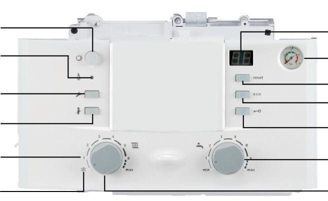
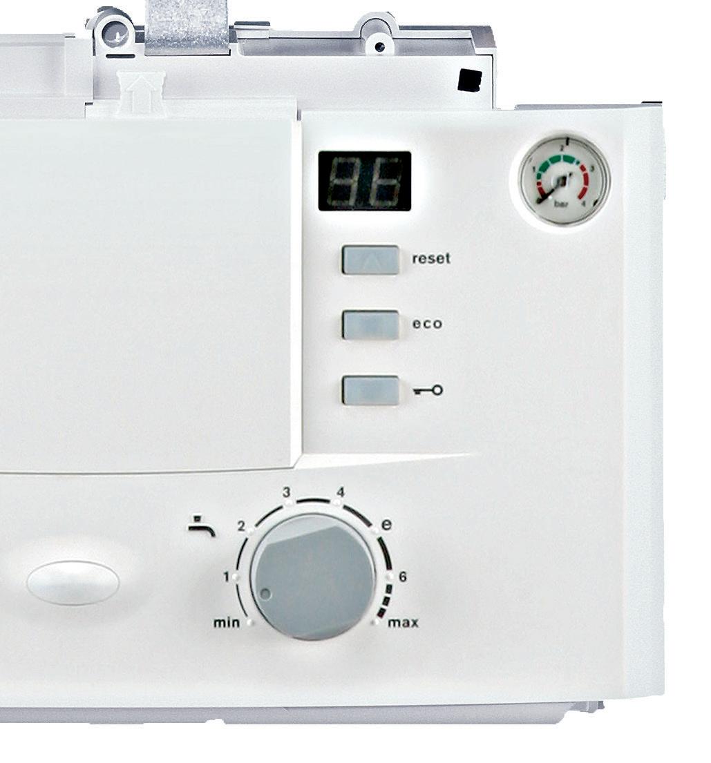
Heatronic III Functions

www.bosch-homecomfort.com | 2
Summer
Display System Pressure Reset Button Eco
Key-Pad Lock DHW Temperature Heating Supply Temperature Frost
Burner
Burner
Lamp
Display
Mode
Button
Protection Service Button
Test Key
Indicator
On/Off Switch
operation, the boiler will modulate as necessary
3 | Bosch Greenstar Boilers | Installer Pocket Guide
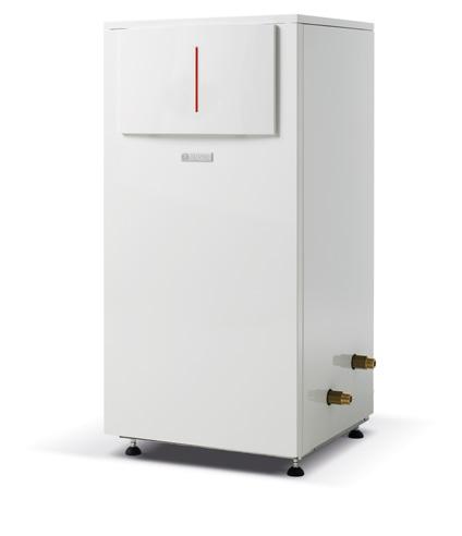
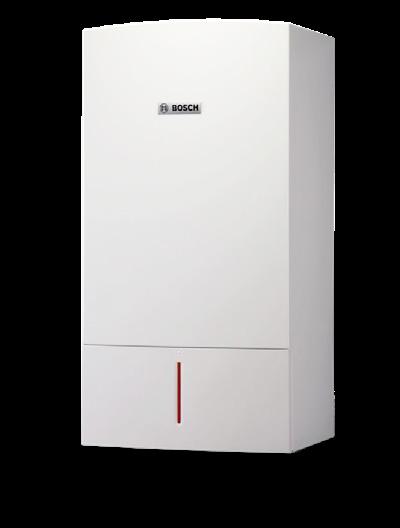
Technical Specifications
Application Space Heating + DHW Models Greenstar Combi 100 Greenstar Combi 131 Greenstar Combi 151 Description ZWB28-3 ZWB35-3 ZWB42-3 Part # 7738100002 7738100256 7713331041 Performance Specifications Fuel NG / LP Input Maximum (MBH) 100.8 131.9 151.6 Input Minimum (MBH) 34.6 36 36 DOE Heating Capacity (MBH) 89.4 116.7 134.4 Net I=B=R (MBH) 79 103 117 AFUE 95.00% 95.00% 95.00% DHW Flow Max (ΔT at 72F) 2.65 GPM 3.2 GPM 4.0 GPM Water Volume 0.952 Gal. (3.5) Technical Data Weight (Without Packaging) 110.2 Lbs. (50) Dimensions W x H x D 17.4" x 33.5" x 13.9" Minimum Recommended Pipe Size 1" Supply Tappings 1" Return Tappings 1" Domestic Cold Water Supply 3/4" Domestic Hot Water Supply 3/4" Gas Connection Size 3/4" Vent Size 2" - 3” Vent Material PVC/CPVC/PP Combustion Air Size 2" - 3" High Altitude Capability No De-Rating up to 6,000' (1829 m) No De-Rating up to 6,000' (1829 m) Derated 3% per 1000 feet (305m) Gas Pressure Minimum w.c. NG 3.5 - LP 8"
Greenstar 79 Greenstar 100 Greenstar 131 Greenstar 151 ZBR21-3 ZBR28-3 ZBR35-3 ZBR42-3 7738100322 7712231415 7712231414 7712231413 NG / LP 79.2 100.8 131.9 151.6 24.6 24.6 36 36 71 89.4 116.7 134.4 62 79 103 117 95.00% 95.00% 95.00% 95.00% - - -- 0.952 Gal. (3.5) 103.6 Lbs. (47) 17.4" x 33.5" x 13.9" 1" 1" 1"3/4" 2" - 3" PVC/CPVC/PP 2" - 3" No De-Rating up to 6,000' (1829 m) Derated 3% per 1000 feet (305m) NG 3.5 - LP 8" www.bosch-homecomfort.com | 4
Space Heating
First Level Service Codes

Display Description 1.A Max.Heating Output 1.b Max. Output DHW 1.E Pump Control Module 1.F Pump Mode 2.A Heating Zone Pump Lockout Time 2.b Max. Supply Temperature 2.C Air Bleed Function 2.d Thermal Disinfection 2.F Operating Mode 3.A Automatic Key Lock 3.b Anti-Cycle Time 3.C Switching Differential 3.d Min. Nominal Output (Heating & DHW) 3.E Cycle Time, Keeping DHW Hot 3.F Duration for Keeping DHW Hot 4.b Max. Heating Temp. of the HEX 4.d Audible Warning Signal 4.E Appliance Type 4.F Trap Filling Function Display Description 5.A Reset Inspection Interval 5.b Fan Run-On Time 5.E Connection NZ - LZ 5.F Set Inspection Interval 6.A Last Fault 6.b Room Temperature Controller, Current Voltage, Terminal 2 6.C Supply Temperature Demand Outdoor Reset Control 6.d Current Volume Flow, Turbine 7.b 3-Way Valve in Center Position 7.d Connection of External Supply Temperature Sensor (e.i. Low-Loss Header) 7.E Building Drying Function 0.A Activate Tank Primary Pump for Recirculation 0.d Adaptation to Elevation Above NN 0.E Set Display Units
Press & hold the Service Button
it lights up. 5 | Bosch Greenstar Boilers | Installer Pocket Guide
until
Second Level Service Codes

+

Display Description 8.A Software Version 8.b Code Plug Number 8.C GFA Status 1) 8.d GFA Fault 1) 8.E Reset All Parameters 8.F Permanent Ignition 9.A Constant Mode 9.b Current Fan Speed 9.C Current Output 9.d Set Start Speed 1 9.E Turbine Signal Delay 9.F Heating Zone Pump Post Purge A.b Water Temperature A.C Current DHW Tank Temperature b.F DHW Heating Delay (Solar Module) C.d Current Heat Demand
Press & hold the Service Button until it lights up. Press ECO button & Key-Pad lock simultaneously until 8.A appears. For more details see installation manual. www.bosch-homecomfort.com | 6
2" Pipe Maximum Lengths
Note: Reference chart in manual for approved venting material.
Installation
2" Pipe Max. Combined Pipe Length Including Elbows in Ft. (m) # of Elbows Greenstar 79 Greenstar 100 Greenstar Combi 100 Greenstar 131 Greenstar 151 Greenstar Combi 131 Greenstar Combi 151 Separate Terminations 1 81' (24.6 m) 65' (19.8 m) 2 76' (23.1 m) 57' (17.3 m) 3 71' (21.6 m) 48' (14.6 m) 4 66' (20.1 m) 40' (12.2 m) 5 61' (18.6 m) 32' (9.8 m) 6 56' (17.1 m) 23' (7.0 m) Stainless Steel Wall Termination 1 76' (23.1 m) 60' (18.3 m) 2 71' (21.6 m) 52' (15.9 m) 3 66' (20.1 m) 43' (13.1 m) 4 61' (18.6 m) 35' (10.7 m) 5 56' (17.1 m) 27' (8.2 m) 6 51' (15.6 m) 18' (5.5 m) Concentric Termination 1 66' (20.1 m) 47' (14.3 m) 2 61' (18.6 m) 38' (11.6 m) 3 56' (17.1 m) 30' (9.1 m) 4 51' (15.6 m) 22' (6.7 m) 5 46' (14.1 m) 13' (4.0 m) 6 41' (12.5 m) 5' (1.5 m) 7 | Bosch Greenstar Boilers | Installer Pocket Guide
Commissioning Maximum / Minimum Settings
Setting CO2 or O2 level for maximum output.
Setting CO2 or O2 level for minimum output.
Note: 4mm Allen Wrench for low fire adjustment. Only fine adjustments will normally be required. A turn of approximately 1/16" can change CO2 values by 0.1%.
Gas Type Maximum Nominal Output Minimum Nominal Output CO2 O2 CO2 O2 NG 9.4% 4.0% 8.6% 5.5% LP/Propane 11.0% 4.2% 10.4% 5.1% 6 720 641 933-81.1O 1 3 2 www.bosch-homecomfort.com | 8
Installation Check Sensor Values
Testing Tolerance ± 10% Resistance (Ω) Outdoor Temperature Sensor °F (°C) - 4 (- 20) 2,392 3 (- 16) 2,088 10 (- 12) 1,811 17 (- 8) 1,562 24 (- 4) 1,342 32 (0) 1,149 39 (4) 984 46 (8) 842 50 (10) 781 59 (15) 642 68 (20) 528 77 (25) 436 Additional Supply Temperature Limiter °F (°C) 32 (0) 33,555 50 (10) 21,232 68 (20) 13,779 86 (30) 9,128 104 (40) 6,205 122 (50) 4,298 140 (60) 3,025 158 (70) 2,176 176 (80) 1,589 194 (90) 1,177 212 (100) 886 9 |
Bosch Greenstar Boilers | Installer Pocket Guide
Testing Tolerance ± 10% Resistance (Ω) Supply Temperature Sensor, Extaernal Supply Temperature Sensor, DHW Tank Temperature Sensor, DHW Temperature Sensor °F (°C) 68 (20) 14,772 77 (25) 11,981 86 (30) 9,786 95 (35) 8,047 104 (40) 6,653 113 (45) 5,523 122 (50) 4,608 131 (55) 3,856 140 (60) 3,243 149 (65) 2,744 158 (70) 2,332 167 (75) 1,990 176 (80) 1,704 185 (85) 1,464 194 (90) 1,262 203 (95) 1,093 212 (100) 950 www.bosch-homecomfort.com | 10
Display Information Obtained 11 | Bosch Greenstar Boilers | Installer Pocket Guide
Display Description
Maximum Output
Maximum Adjustable Heating Output
Display Description
Service Necessary Pump Has Seized
Minimum Output Buttons Locked


Trap-Filling Program Active
Air Vent Function Active
Gradient Control (Too Rapid Increase of the Central Heating Flow Temp., Heating Interrupted 2 Mins)
Value Stored
Symbol After Pushing 1 Button Symbol After Pushing 2 Buttons at the Same Time


Floor Drying Program Active (To Activate a Weather Controller)
Over Temperature 212°F - 228°F
100°C - 109°C
www.bosch-homecomfort.com | 12
Error Codes
Display Description
A7
DHW Temperature Sensor Defective
A8 Communication Fault
Ad
DHW Tank Temperature Not Detected
Solution
Check temperature sensor & leads for interruptions or shorts, & replace if defective.
Insert code plug correctly, replace if defective.
Check BUS communications wiring, replace if defective.
Check control, replace if defective.
Check DHW tank temperature sensor & connecting lead, replace if defective.
The DHW Tank Temperature Sensor was Recognized Before the Connection was Lost
b1 Code Plug Not Detected
b2 / b3 / b4 / b5 / b6 Internal Data Error
b7 Fault in the Burner Controls
C6 Fan Not Running
Reset the boiler to the factory default settings (service function 8.E), reset the IPM2 (if installed) to the factory default settings & carry out the automatic system configuration.
Insert code plug correctly, replace if defective
Reset boiler to factory default settings (service function 8.E).
Reset boiler to factory default settings (service function 8.E).
Check fan leads & fan, replace if defective.
CC Outdoor Temperature Sensor Not Recognized
Check outdoor temperature sensor & leads for interruptions, replace if defective.
Verify the outdoor temperature sensor is connected to terminals A & F.
13 | Bosch Greenstar Boilers | Installer Pocket Guide
Display Description
Temperature High Limit Defective
d3
External Guard has Tripped Temperature Limiter Locked Out
External Supply Temperature Sensor Defective (Low-Loss Header)
d5
The External Supply Temperature Sensor was Recognized on the BUS & then Reconnected to the Appropriate Terminal
E2
Supply Temperature Sensor Defective
E3
Additional Supply Temperature Sensor Defective
Solution
Check temperature sensor & leads for interruptions or shorts, & replace if defective.
Temperature guard TB1 has tripped. Check if jumper across 8-9 or PR-PO is missing.
Reset external temperature limiter (if installed).
Reset LWCO (if installed).
Check temperature sensor & leads for interruptions for shorts, & replace if defective.
Check whether only one temperature sensor is connected; otherwise remove second termperature sensor.
Check temperature sensor & leads for interruptions or shorts, & replace if defective.
Check temperature sensor & leads for interruptions or shorts, & replace if defective.
Check flue gas safety high limit & leads for interruptions or shorts, & replace if defective.
E9
Heat Exchanger Safety High Limit or Flue Gas Temperature Limiter Has Tripped
Check heat exchanger safety high limit & leads for interruptions or shorts, & replace if defective.
Check the operating pressure.
Continued on next page
www.bosch-homecomfort.com | 14
Error Codes Continued
Display Description
Solution
Check temperature limit; replace if defective.
Check pump capacitor; replace pump if defective.
E9 Continued Heat Exchanger Safety High Limit or Flue Gas Temperature Limiter Has Tripped
Check PCB fuse, replace if blown (6.3 A fuse according to IEC default).
Purge the appliance.
Check heat exchanger on the DHW side; replace if clogged.
No Flame Detected
EA
GFA: Safety Time Expired
Check that ground lead is properly connected, replace if defective.
Check that gas cock is open.
Check inlet gas pressure; correct if needed.
Check power supply.
Check electrodes for visual damage; replace if defective.
Check gas/air ratio; correct if out of range.
Check gas valve; replace if defective.
In room air operation, check air supply or ventilation aperatures.
Continued on next page
15 | Bosch Greenstar Boilers | Installer Pocket Guide
Clean the condensate trap.
Remove diaphragm at fan inlet connection & check for contamination or cracks.
Check heat exchanger for soiling (Chapter 14.1.6, page 84).
Check gas cock; replace if defective.
Insert code plug correctly; replace if defective.
Press reset for 3 seconds & release. When the button is released, the appliance will restart.
Check electrical plug-in contacts & ignition leads; replace PCB if defective.
Check gas/air ratio; correct if out of specification.
Reset boiler to the factory default setting (service function 8.E).
Check electrodes; replace if defective.
Check flue gas system; clean or repair if defective.
Check PCB for moisture; dry if needed.
Display Description Solution EA Continued No Flame Detected GFA: Safety Time Expired
F0 Internal Fault
Internal Data Error
F1
Even
F7 Flame Detected
When Burner is Off
www.bosch-homecomfort.com | 16
Error Codes Continued

Display Description
Solution
Check gas cock; replace if defective.
Clean condensate trap.
FA After Switching Gas Off: Flame is Detected
Check electrodes & leads; repair if defective.
Check flue gas system; clean or repair if needed.
Press reset button again.
Fd Reset Button Pressed by Mistake
Check cable harness to safety high limit & gas cock for ground connection.
Fully open service shut-off valves.
Check electrical connection between heating zone pump & Heatronic III.
Temperature Gradiant Limiter: Temperature Rise Too Fast
Check pump plug connection per installation instructions.
Manually test operation of heating zone pump & replace if defective.
Set pump speed correctly to match maximum output.
17 | Bosch Greenstar Boilers | Installer Pocket Guide
LP Gas Recommissioning Adjustments
This table indicates the approximate number of turns required to ignite the direct vent boiler appliance listed above, when a SIT gas valve has been fitted.
The number of turns has been counted from when the maximum and minimum adjustment has been wound fully closed.
These are approximate figures for LPG appliances.
A combustion analyser must be used to set to 11% maximum CO2 and 10, 4% minimum CO2.
www.bosch-homecomfort.com | 18 Number of Turns from Gas Valve Fully Wound Home Model Maximum Setting Minimum Setting Greenstar Combi 151 3/4 turns 3 and 1/2 turns Greenstar 151 3/4 turns 3 and 1/2 turns Greenstar Combi 131 3/4 turns 3 and 1/2 turns Greenstar 131 3/4 turns 3 and 1/2 turns Greenstar Combi 100 1/2 turns 3 turns Greenstar 100 1/2 turns 3 turns Greenstar 79 1/2 turns 4 and 3/4 turns
LP Gas Recommissioning Adjustments
INFORMATION REGARDING THE CONVERSION OF THE BOSCH GREENSTAR BOILERS FROM NATURAL GAS TO LIQUID PROPANE
FLUE GAS ANALYZER MUST BE USED:
The range of Bosch Greenstar boilers are supplied in ready to use on Natural Gas (NG). If the installation requires Liquid Propane (LP) as the fuel then the boiler will have to be converted. The information regarding how to convert the boiler from NG to LP is contained within the installation manual, but as a summary, the process is as follows. The “code plug” that is provided with the boiler is set for natural gas. This will have to be changed for the LP “code plug”, by removing the rear cover from the electrical panel, removing the NG code plug and replacing it with the LP code plug.
Note: There is an orifice supplied with the boiler that needs to be installed. Once this has been installed the boiler MUST be re-commissioned with a flue gas combustion analyzer. Boilers installed prior to 2018 did not come with an orifice and one is not needed.
If the contractor/commissioning engineer does not have a calibrated flue gas combustion analyzer on site then the boiler MUST NOT be used, until it has been re-commissioned to the required parameters stated in the Bosch Greenstar installation manual.
19 | Bosch Greenstar Boilers | Installer Pocket Guide
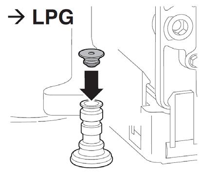
Repacing the code plug
Note: Install fixed gas throttle for LPG
Tab. 30 CO2 or O2 values at maximum and minimum nominal output
The boiler commissioning process for NG and LP can be found in the Bosch Greenstar installation manual.
Note: To commission any of the Bosch Greenstar range, a flue gas analyzer must be used whether the fuel is NG or LP.
www.bosch-homecomfort.com | 20 Maximum Nominal Ouput Minimum Nominal Ouput Gas Type CO2 O2 CO2 O2 NG 9.4% 4.0% 8.6% 5.5% LPG (Propane) 11.0% 4.2% 10.4% 5.1%
6 720 641 933-57.1O
Notes Display Description Elimination 21 | Bosch Greenstar Boilers | Installer Pocket Guide
Notes Display Description Elimination www.bosch-homecomfort.com | 22
Bosch Home Comfort Group Watertown, MA | Londonderry, NH | Ft. Lauderdale, FL General Inquiries: 1-866-642-3198 Copyright © 2023 Bosch Home Comfort Group All rights reserved. Subject to change without notice. 77799405E 5-23 www.bosch-homecomfort.us
