Designing for Zero Carbon
Volume 2
Case Studies of All-Electric Multifamily Residential Buildings
 Written by Edward Dean, FAIA Bernheim + Dean Inc.
Foreword by Jessica Granderson Interim Director
Iain Walker Staff Scientist
Written by Edward Dean, FAIA Bernheim + Dean Inc.
Foreword by Jessica Granderson Interim Director
Iain Walker Staff Scientist
Building Technology and Urban Systems Division
Lawrence Berkeley National Laboratory
July 2023
Designing for Zero Carbon
Volume 2
Case Studies of AllElectric Multifamily Residential Buildings
Written by Edward Dean, FAIA Bernheim + Dean Inc.
Foreword by Jessica Granderson Interim Director
Iain Walker Staff Scientist
Building Technology and Urban Systems Division
Lawrence Berkeley National Laboratory
2023
July
The publication of this book is funded by California utility customers and administered by Southern California Edison®. Southern California Edison is regulated by the California Public Utilities Commission.
Copyright © 2023 by Southern California Edison
All rights reserved. No part of this book may be reproduced in any manner without written permission, except in the case of brief quotations embodied in critical articles and reviews. These materials were prepared to be used in conjunction with a free educational program and are not intended to provide legal advice or establish legal standards of reasonable behavior. All images reproduced in this book have been included with the knowledge and prior consent of the photographers and other professionals concerned. Southern California Edison and any of its employees and agents: (1) do not make any written or oral warranty, expressed or implied, including, but not limited to, those concerning merchantability or fitness for a particular purpose; (2) do not assume any legal liability or responsibility for the accuracy or completeness of any information, apparatus, product, process, method, or policy contained herein; and (3) do not represent that its use would not infringe any privately-owned rights, including, but not limited to, patents, trademarks, or copyrights.
Published in the United States of America 2023 Southern California Edison Los Angeles, California sce.com
ISBN: ### Library of Congress Cataloging-in-Publication (CP) Data available upon request.
This publication is available as a printed softcover book through Amazon, amazon.com/books
Photographs by: Chipper Hatter, Chris Ricketts, Bruce Damonte. Cover Photo: Chipper Hatter, San Diego, CA
Energy Performance Graphs & Charts: Edward Dean FAIA, Bernheim + Dean Inc.
ii
Foreword by Jennifer Granderson and Iain Walker, Lawrence Berkeley Laboratory iv Introduction viii Case Study Projects 1 Case Study No. 1: Ivy Senior Apartments 2 Case Study No. 2: Rosecrans Place 24 Case Study No. 3: Vera Cruz Village 42 Case Study No. 4: The Palo Alto Apartments 68 Case Study No. 5: Casa Adelante at 2060 Folsom 92 Conclusion 115 Epilogue - Additional Exemplary All-Electric Multifamily Residential Projects 116 Observations 128 Acknowledgments 132 iii
Table of Contents
Foreword
California is a long-recognized leader in clean energy, climate and building policy. Recent federal action presents a unique window of policy alignment that promises to amplify dramatically our progress toward the energy transition. California was the second state in the nation to legislate greenhouse gas emissions reduction requirements, and soon thereafter, requirements were enacted to direct proceeds from cap and trade credits to disadvantaged communities. Addressing energy supply, the state set a goal of zero-carbon electricity by 2045, and on the demand side, building energy codes are driving electrification, storage, and ever-deeper efficiency levels across the state. Federally, the U.S. Congress has legislated historic climate investments on the order of hundreds of billions of dollars, and to ensure that benefits accrue to justice communities, the Biden-Harris Administration has launched the Justice40 Initiative.
Equitably decarbonizing our buildings will require expanding efforts in the residential sector beyond our historic emphasis on single-family homes. 42% of California’s low-income residents live in multifamily buildings (see figure on opposite page).
In just the last few years, we have seen a remarkable industry-wide shift to embrace zero and net-zero emission building performance as our collective “North Star”. We now understand that this means we have to clean the electricity supply, electrify, and continue improving efficiency –particularly in the envelopes of older buildings. There is also growing recognition that to increase system reliability and minimize costs, our buildings must also provide load flexibility to coordinate with a renewable grid.
The Clean Energy Act is already accelerating a clean energy supply, and the building code is driving solar photovoltaic (PV) systems, energy storage and electrification in the multifamily sector. With this policy backdrop in place, today’s multifamily design and delivery professionals must focus on electrification done right, thereby setting the stage for all of our communities to benefit from our low-carbon transition.
Electrification done right means first getting the envelope right. In the zero-emission multifamily context, California’s building energy codes already require efficient thermal performance for windows and opaque facades. However, airtightness is not addressed and more attention is required to appropriately control flows between inside and outside, as well as internal flows. Both have impacts on energy and indoor air quality. These well-performing envelopes require more careful solar control to avoid overheating. Shading, orientation and glazing all become increasingly important if we are to avoid excess energy use for air conditioning in summer months.
With a well-designed envelope, space heating and cooling can be delivered more effectively. In multifamily buildings that offer unit-based electric heat pump systems, there are architectural and engineering challenges associated with locating the outdoor components. Accounting for both aesthetics and ease of installation/maintenance is important, particularly for high-rise buildings. Outdoor units are often sited on rooftops, requiring thought as to the location of vertical refrigeration lines and the large amount of refrigerant required for longer line sets. In addition, rooftop space is limited, and is also valuable for rooftop solar PV or solar water heating systems.
Water heating is often centralized in multifamily buildings, which can require creative design to overcome the lack of market-available heat pumps that have the capacity of large central boilers. Higher capacity may be achieved by leveraging thermal storage (including phase-change materials). This approach also has the advantage of limiting the peak power required for hot water. Other considerations include acoustic and installation issues. Many in-unit heat pump water heating devices are noisy, or do not come in form factors suitable for apartments. Improvements in water distribution design should also be considered, such as shorter, smaller diameter piping, and improved controls for circulation pumps.
iv Case Studies of All-Electric Multifamily Residential Buildings DESIGNING FOR ZERO CARBON, VOL. 2 FOREWORD
(Below) Numbering over 10 million, multifamily residences represent approximately one quarter of California’s housing stock. 32% of Californians— over 12 million people—live in low income households and 42% of them live in multifamily buildings.
Distribution of Income1 in California & Residential Building Types Occupied by Low-Income Californians2
1 The income levels in this chart are based on the Department of Housing and Urban Development (HUD) defintions in its categories of Area Median Income (AMI), namely:
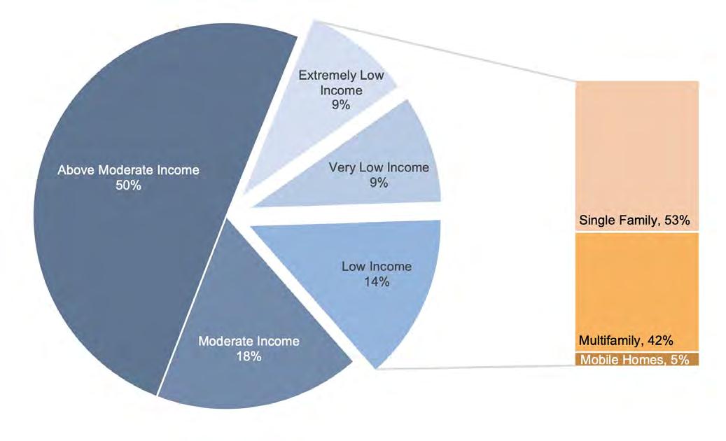
The AMI for an “area” (also defined by HUD) is the midpoint of the area’s income distribution (the “median”). The number of households in each category are tabulated for each “area” of California and added together to give the total number of California households in each income level as shown in the chart.
2 Source: Reem Rayef, August 2020. https://www.veloz.org/wp-content/uploads/2021/09/Housing-Equity-and-Building-Decarbonization_FINAL_Sept-2020-1.pdf
v Case Studies of All-Electric Multifamily Residential Buildings FOREWORD DESIGNING FOR ZERO CARBON, VOL. 2
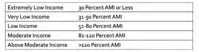
Demand flexibility is becoming increasingly important as we rapidly electrify buildings and transportation, transitioning to 100% clean energy. (See graphic on the opposite page, which illustrates the four principal areas of building decarbonization.) Central batteries or thermal storage systems can enable this flexibility, as well as enhanced resilience during power failures, but they also bring additional space needs. Emerging power-efficient (low maximum power) heating, cooling, hot water systems and appliances, as well as smart panels and circuit-sharing devices, will aid in controlling maximum power requirements. This can eliminate the need for costly electrical upgrades.
Finally, California policy is accelerating a transition to electric vehicles (EVs), which are increasingly integrated with our building infrastructure. Designers now need to provide more EV charging capability, and must do so in a way that accounts for EV needs 20 years from now. As with other large loads, there is value to managing EV charging in real time using smart chargers to minimize peak demand while providing enough service flexibility for occupants.
Net-zero multi-family housing is here today, and building professionals are becoming more experienced in navigating the attendant tradeoffs in space, capacity and cost. We are seeing that engineering and design challenges can be overcome even as new technologies are coming to market that will make net-zero multifamily buildings easier to design, build and maintain. Delivered alongside policies to shield the most vulnerable from higher utility bills, their benefits will carry us far beyond the basic climate impacts. In addition to energy considerations, electric buildings with storage are more resilient, and their avoided combustion emissions improve both indoor and outdoor air quality, leading to healthier built environments.
Jessica Granderson, Interim Director


vi Case Studies of All-Electric Multifamily Residential Buildings DESIGNING FOR ZERO CARBON, VOL. 2 FOREWORD
Building Technology and Urban Systems Division Lawrence Berkeley National Laboratory
vii Case Studies of All-Electric Multifamily Residential Buildings FOREWORD DESIGNING FOR ZERO CARBON, VOL. 2 vii
(Graphic courtesy of Lawrence Berkeley National Laboratory.)
Introduction
This book of case studies is the second volume of the sub-series1, Designing for Zero Carbon This sub-series focuses on the electrification of buildings, a current aspect of California state government policy to combat climate change and its effects. Volume 1, published in March 2022, considered case studies of recent projects that were non-residential, both new buildings and renovations. This Volume 2 continues the narrative of zero-carbon buildings, but focuses on the important category of multifamily residential projects.
Energy efficiency remains an important goal, as reflected in the steady tightening of California’s Title-24 energy code requirements, and the role of on-site renewable energy sources continues to grow. But, as discussed in the Introduction to Volume 1, full decarbonization of the building sector will only be realized when the use of carbon sources of energy in buildings such as natural gas is eliminated and the electric power grid is itself fully decarbonized. The latter goal is mandated2 to be achieved in 2045.
The transition to all-electric operation of buildings, both new and existing, is the formidable task that lies ahead for the building industry. As usual, California’s Title-24 energy code sets the direction for the industry to follow, but much can be done outside of code requirements to advance the state of the art in this regard, both technically and in a cost-feasible manner.
The challenge to building developers, owners and design professionals, then, is to find the opportunities to utilize electric energy systems in place of gas systems while striving for cost-efficiency and quality design. In this Volume 2, multifamily residential buildings take center stage, featuring many successful projects that achieved this goal.
The Multifamily Residential Challenge
The category of building labeled “multifamily” is quite broad and actually includes many types of structures and uses. There are code definitions of types of multifamily structures with slight differences (California Building Code and California Energy Code), but this book will use the simple definition of a multifamily building as one with three or more dwelling units for permanent residents. Consistent with the 2023 California Energy Code, the multifamily buildings discussed in this volume are both low-rise (three or fewer habitable levels) and high-rise (four or more habitable levels); that is, buildings of any height. Furthermore, groupings of attached townhouses (three or more) will also be the subject of discussion in this volume, as well as buildings of mixeduse housing and commercial.
The appropriate design of the energy systems in this range of structures will vary significantly, so each type of multifamily building and occupancy will be discussed in this regard. Further, the design and its associated cost will also be a significant factor in the choice of system, usually dependent on whether the dwelling units are to be rented or sold. Adding yet one more facet to this set of factors in the case of rental housing, if the multifamily building is designated as “afford-
1 The full series of seven case study books, which were published about a year apart starting in 2014, covers an expansive range of building types to support the adoption of energyefficient, low-carbon building design practices in California. These books can be found and downloaded for free from https://calbem.ibpsa.us/resources/case-study-books/. They are also available on Amazon in softcover print form at: https://www.amazon.com/s?k=zero+net+energy +case+study+buildings&i=stripbooks&ref=nb_sb_noss
2 Governor’s 2018 Executive Order B-55-18 and SB-100, the state law passed that same year. See also: March 2021 Joint Agency Report Summary, “Achieving 100% Clean Energy in California”, https://www.energy.ca.gov/publications/2021/2021-sb-100-joint-agency-reportachieving-100-percent-clean-electricity
Case Studies of All-Electric Multifamily Residential Buildings DESIGNING FOR ZERO CARBON, VOL. 2 INTRODUCTION
viii
able housing” the choice of energy system may again be different if the costs are borne by the owner rather than the tenant.
Aside from the design of the energy system and the nature of the building structure itself (wood frame, heavy timber, concrete, steel), other related issues have become pressing in recent years, making the design of multifamily residential projects even more challenging.
Grid Harmonization and Resiliency — Energy Storage
In the Introduction to Volume 1 of Designing for Zero Carbon3, the issue of the statewide uneven demand for electric power throughout the day was discussed as a growing issue of concern. This “Duck Curve” phenomenon4 (the growing peak power demand in the evening hours and the decreasing lower demand in the midday period caused by increased use of on-site solar PV systems for buildings in California) suggests the use of energy storage to enable the public utility grid to moderate and manage the extremes of the daily energy demand.
The public utility companies already use time-of-use rates to help manage this growing demand fluctuation, charging significantly more for electric energy used during the afternoon and evening compared to much lower rates charged after midnight and in the early-morning hours. As electric vehicles further penetrate the automobile market, this load shifting will become much more significant.
Energy storage will be introduced to some extent at the public utility level, but its primary application will be at the individual building level, installed by building owners in conjunction with their solar PV systems. On-site battery storage will enable building owners to store unused electric energy generated during the sunny daytime hours for use later in the evening when the utility rates are much higher. The ability to manage the electric power drawn from the utility grid in this manner will contribute to the overall cost effectiveness of the battery storage systems.
Another benefit of on-site energy storage for the individual building owner is the resiliency offered by such a feature during periods of utility power interruption such as California experienced recently during periods of wildfires and extreme weather events. The value of this resiliency feature is not measured in a standard cost-effectiveness evaluation, but nevertheless may be high in the estimation of the final users of the building.
In fact, for multifamily residential projects of four stories or more that are in the design and permitting phase, and for all such multifamily residential projects in the future in California, battery storage is now required along with a solar photovoltaic system.5
Embodied Carbon
Embodied carbon considerations are being included during the design phases as carbon reduction for new buildings becomes more urgent in our societal effort toward the 2030 carbon reduction goals. Energy efficiency has been built into building projects for the past four decades in California and has been improved every code cycle. The move to all-electric buildings and the scheduled decarbonization of the public utility grid will eventually lead to a zero-carbon building sector from an operations perspective. A strong effort is therefore now being made by design professionals and others to reduce the embodied carbon in building materials that occurs due to
3 See p. viii of Volume 1.
4 Burnett, M., “Energy Storage and the California Duck Curve”, Stanford University (2015).
5 2022 California Energy Code, effective January 1, 2023.
Case Studies of All-Electric Multifamily Residential Buildings INTRODUCTION DESIGNING FOR ZERO CARBON, VOL. 2 ix
the carbon emissions from their manufacture and production, transportation to the building site and the construction process itself.
This is a fairly recent concern in the building industry and the analytical tools available to design professionals have become widely available only in the past several years.6 Thus, widespread adoption of embodied carbon analysis during the design phase of projects has yet to occur. Such analysis can suggest alternative building products, materials and structural systems, even whether to renovate or build new. (Projects in this volume that analyzed embodied carbon during the design and the results of those analyses are duly noted in the project discussions.)
Future Planning: Electric Vehicle Accommodation
Another challenge that has arisen during recent planning for multifamily residential projects is the infrastructure required for EVs. There has been a rapid adoption of the EV since its public introduction fifteen years ago, particularly in California. In addition to its advantage to the consumer, the decarbonization potential of the transportation sector is remarkable. To help accelerate this change, California has mandated7 that all new cars sold in California after 2035 must be zeroemission vehicles—new internal combustion gasoline-powered cars will no longer be available for sale in the state. Planning for the car-charging infrastructure that will be required, particularly for multifamily residential, is now essential.
Projects discussed in this volume completed the planning and design phases, and in some cases were under construction, when this state mandate was issued. Nevertheless, anticipating the future requirement, some of the projects provided for future installation of car-charging systems on site. Going forward, this local system will be a program requirement for owner, tenant and/or staff.
Affordable Housing
A large portion of the multifamily residential projects discussed in this volume meet the California Department of Housing and Community Development definitions of affordable housing. This is in part due to the commitment of the non-profit developer community to low-carbon solutions. Since these solutions must also be cost conscious, the affordable housing projects depicted here present important lessons in that regard, applicable to other types of multifamily housing.
By way of definitions used to characterize the affordable housing projects in this volume, the following apply8:
• AMI – Area Median Income. Eligibility for a particular affordable housing project is typically set as an income level within a percentage range of the AMI and the number of persons in the household.
• Income Category Level. Designations such as “Low-Income”, “Very Low-Income”, etc., are defined as a certain percentage of the AMI in a certain area, adjusted for household size.
An applicant may qualify for a project designated for low-income tenants, for example, if their income falls within the formal definition of that category. Developers may further limit the tenant
6 See p. 111 of this book.
7 Governor’s 2018 Executive Order N-79-20 and the California Air Resources Board Advanced Clean Cars II Rule (Nov. 30, 2022).
8 See also the Foreword to this book, p. iv.
Case Studies of All-Electric Multifamily Residential Buildings DESIGNING FOR ZERO CARBON, VOL. 2 INTRODUCTION x
population by age (“senior housing”), social group (“formerly homeless veterans”) or special needs (“transition-age youths”).
The Multifamily Case Study Projects in This Book
Similar to previous volumes in this series, five projects were selected as both representative of exemplary design and also a variety of building types across a range of California climates. These were selected from a list of almost fifty candidate projects, all recently completed and successful in their all-electric design features and performance. They include new and renovation projects, market-rate or affordable housing, and rental units as well as buildings with units for sale.
Because of this large diversity of types of multifamily residential projects as described above, an additional nine projects were selected and summarized in the Epilogue section of this book. These additional projects have a particularly unique aspect of their program, building structure or financial constraints that make them especially noteworthy. Though not detailed case studies like the five featured projects, the summary information provides comparative data and leads to follow-up with further study.
The following page shows a diagrammatic map of California with the locations of the five case study projects. The locations of the remaining candidate projects that were examined in the development of this book are indicated in the same map to demonstrate that the adoption of the all-electric design approach has had widespread distribution throughout the state. A detailed version of this map, identifying and locating all the projects, appears in the Epilogue section beginning on page 116.
These projects communicate the breadth and scope of electrification in multifamily projects already happening throughout the state. In fact, this trend is accelerating and is not limited to just one type of housing construction, as the range of projects in this volume shows.
Hopefully, the projects discussed in this volume will provide design professionals with tangible examples of electrification success stories to help them in their work as the code moves to favor integrated renewables with electrification.
Case Studies of All-Electric Multifamily Residential Buildings INTRODUCTION DESIGNING FOR ZERO CARBON, VOL. 2 xi
The Case Study Projects:
Location of case study project
Location of additional all-electric multifamily projects — see detailed project map and list on p.116, Epilogue section.


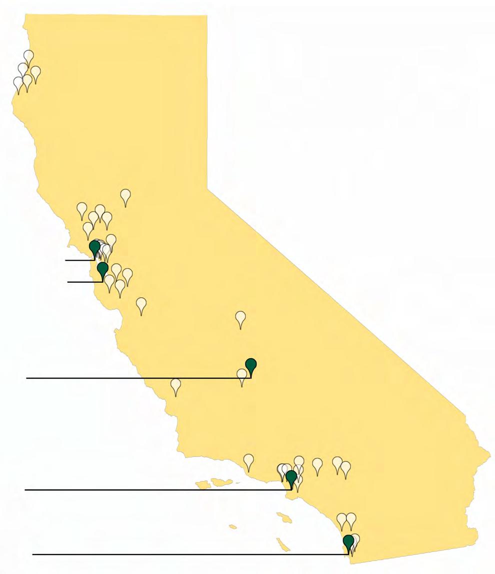
Casa Adelante, San Francisco
Palo Alto Apartments, Palo Alto
Vera Cruz Village, Richgrove
Rosecrans Place, Gardena
Ivy Senior Apartments, San Diego
xii Case Studies of All-Electric Multifamily Residential Buildings DESIGNING FOR ZERO CARBON, VOL. 2 INTRODUCTION
Case Study Projects
1
Ivy Senior Apartments
CASE STUDY NO. 1 2
3
PHOTO: CHIPPER HATTER
Ivy Senior Apartments
Case Study No. 1
Data Summary
Project Type: Affordable Housing (New)
Location: San Diego, CA
California Climate Zone: 7
Clientele: Formerly Homeless Seniors
Gross Floor Area: 39,487 sq.ft.
Fully Occupied: 11/2021
Modeled EUI (Site): 22.0 kBtu/sq.ft. per year
Measured EUI (Site): 16.0 kBtu/sq.ft. per year
On-Site Renewable Energy System Installed: 43.05 kW (DC) Solar PV
On-Site Storage Battery: None
Measured On-Site Energy Production: 81,937 kWh per year 7.1 kBtu/sq.ft. per year
Affordable housing is a pressing need in California and much is currently being done to address this problem, even beyond historic federal and state government programs that provide funding to build and/or operate multifamily housing projects for low-income citizens. Typically, federal and state programs have been initiated to make it feasible for non-government, non-profit organizations to plan, build and manage housing projects that meet a mandated definition of “affordable”. Funding provided by these agencies to operate these types of housing projects offsets the difference in total operating costs to the non-profit organizations and the maximum allowed rental income as defined by current federal and state regulations. This maximum is determined by the type of affordable housing for which a particular project has been designated and approved, typically Low-Income, Very Low-Income or Extremely Low-Income.1
Similarly, to be eligible for tenancy in an affordable housing project, an individual or household must show evidence that the household income does not exceed the amount set by the state funding agency, adjusted for size of household as specified by regulation and the specific geographic area of the state. California law defines an Area Median Income (AMI) for each these locations in the state and, based on the size of the household and designation of the project (Low-Income, etc.), the income limit for the tenant is determined from the regulation.
This first case study is that of an affordable multifamily housing project, like two other case study projects in this book.2 However, it was specifically initiated to serve only the part of the population that is designated as seniors (age 55+) in the Low-Income category. The project documentation lists the maximum rent at 30% AMI in half the units and 50% AMI in the remaining half, which in San Diego at the time of project approval was $636/month and $1,061/month, respectively.
Background
Owner/Client
Wakeland Housing and Development Corporation, San Diego, CA
Design Team Architect: BNIM, San Diego, CA
Structural Engineer: DCI Engineers, San Diego, CA
Mechanical, Electrical and Plumbing Engineering: Green MEP, Newport Beach
Energy Modeling: g.r.e.g. Consulting, Carlsbad
General Contractor:
Allgire General Contractors, Carlsbad, CA
Solar Contractor: Cal Solar Inc., San Diego, CA
Founded in San Diego, Wakeland Housing and Development Corporation, the non-profit company that initiated this project, specializes in creating and managing new affordable housing communities in California. Since its founding in 1998, the company has developed 7,500 affordable housing units at 53 sites in the state. Wakeland also has a third-party management company to administer and operate their completed projects, with third-party service providers.3
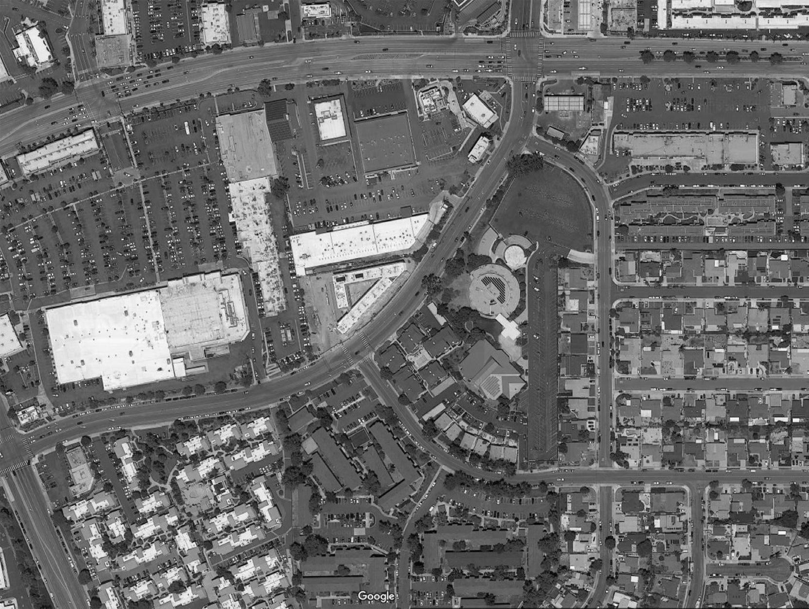
The project site was already occupied by a commercial building when Wakeland considered it for a new building site in late 2017. It was slated for redevelopment by the City of San Diego and had been listed for sale by a broker. The site was particularly attractive to Wakeland because of its location on the north side of San Diego, where no affordable housing was yet available. In terms of local features, the site was near other neighborhood amenities such as shopping, schools and public transit. Furthermore, its size and configuration could accommodate the number of units typically desired for this type of housing (~50) with some surface parking for staff and visitors and a generous space for an outdoor commons area.
1 See “State Income Limits for 2022”, Department of Housing and Community Development, 13 May 2022, https://www.hcd.ca.gov/docs/grants-and-funding/inc2k22.pdf
2 Case Study No. 3, Vera Cruz Village, p. 42; Case Study No. 5, Casa Adelante - 2060 Folsom, p. 90.
3 The third-party service providers at Ivy Senior Apartments are the following organizations: PATH (“People Assisting The Homeless”), St. Paul’s PACE (“Program of All-inclusive Care for the Elderly”) of San Diego, and the Alpha Project Home Finder Program (a non-profit organization funded by the county of San Diego Behavioral Health Services Department, which funds homeless services).
4 CASE STUDY NO. 1 IVY SENIOR APARTMENTS Designing for Zero Carbon: Volume 2
5 IVY SENIOR APARTMENTS CASE STUDY NO. 1 Designing for Zero Carbon: Volume 2
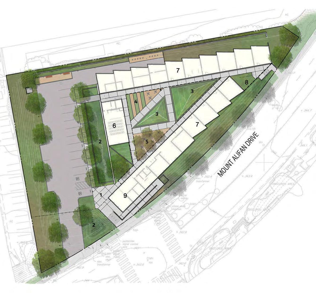
Ivy Senior Apartments - General Vicinity Plan
Mt.AguilarDrive
Mt.Alifan Drive
Given all the positive aspects of this particular site, Wakeland acquired it in January 2018 with a local funding partner.4 Land cost at the time was approximately $70,000 per unit, or $3.5 million. To design and build the project, Wakeland organized funding from ten organizations, including state and local agencies.5
The general clientele for Wakeland projects is people who are “formerly homeless”. There was initial concern in the neighborhood about a project aimed at this general group, especially since there was no previous development of affordable housing for them in this part of San Diego. “Formerly-homeless seniors” is a sub-group that allayed some of this local concern and there was coincidentally also a great need for this type of affordable housing in this area. Wakeland therefore decided to design the project for this type of resident. As it turned out, some project opponents visited a previous Wakeland project for formerly-homeless seniors as part of the neighborhood informational outreach in the city approvals process and were impressed with the project quality. As a result, the project was able to move forward with this design intent and user clientele.
4 Acquisition financing was provided by Century Housing Corporation, Culver City, a nonprofit lender to developers building affordable housing targeting low- and moderate-income wage earners.
5 The California Tax Credit Allocation Committee awarded Wakeland with Low-Income Housing Tax Credit (LIHTC) tax credits in the category of 9% Tax Credits for new housing units. This enabled Wakeland to obtain construction financing from Wells Fargo Bank, who also purchased the tax credits. Additional funding was provided by The San Diego Housing Commission, the City of San Diego, the CalHFA Special Needs Housing Program (administered by the County of San Diego), the California Community Reinvestment Corporation and the Federal Home Loan Bank of San Francisco Affordable Housing Program.
6 CASE STUDY NO. 1 IVY SENIOR APARTMENTS Designing for Zero Carbon: Volume 2
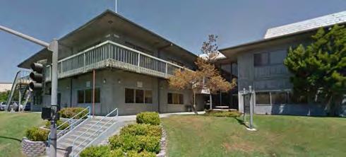
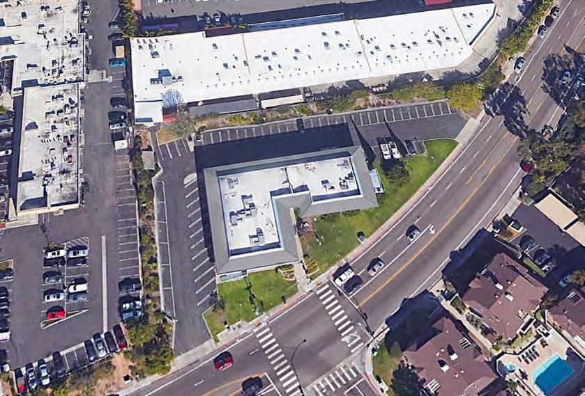
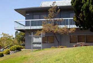
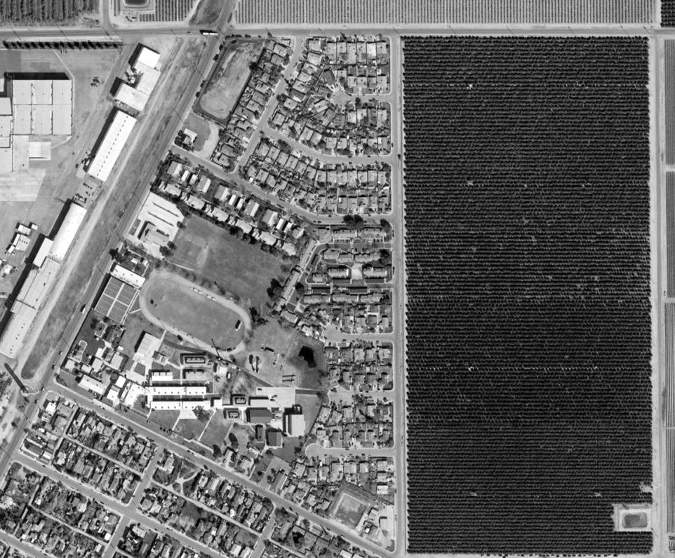
(Right and Below) Project site in 2017, prior to demolition of the existing two-story office building.
Design Process and Low-Energy, Zero-Carbon Design Strategies
Early in 2018, the architect and engineering firms were solely and separately invited to submit proposals for the project, which included an initial study for the building program and conceptual design. The invitations were extended based on the firms’ previous work and reputation. The design and approval process took place during 2018-2019 and construction began in 2020, with occupancy beginning in the fall of 2021.
Fundamental to the project planning was the design requirement of a low-energy, all-electric building. Now adopted as general policy for all their housing developments, the all-electric approach was required by Wakeland for a number of reasons. For formerly-homeless seniors, who often have chronic health issues, indoor air quality is a particular concern. Gas space heating, water heating and appliances present certain risks in this regard.6 In addition, the global issue of decarbonization of their housing stock has become a principal policy determinant for Wakeland. Indeed, the design team was selected based on their proven expertise in the design of ZNE and zero carbon buildings (operationally).
Building Program
The pre-design phase of the project involved development of a building program and a conceptual design for the selected site. Given the site geometry and other constraints, the concept design maximized the number of studio apartments for the elderly clientele, while providing the number of parking spaces required by the planning code. In addition, there were requirements for certain administrative spaces, a health services suite and common spaces.
The designers managed to develop a plan that provided 52 studio apartments (plus one twobedroom apartment for the on-site manager) on the small site, all of which are ADA and California Title 24 Accessibility code compliant, and 16 parking spaces for staff and visitors. Local zoning limited the total number of units to 33, but an exception was made for this project per California’s Density Bonus Law/AB 2162.
Because of the triangular shape of the site and the mandated height limit, the building is a threestory structure consisting of three wings surrounding a central outdoor space. The common areas are all located at ground level.
There is a reception space with mailboxes near the main entry, along with the administrative office and health service facilities. Shared common areas include a large meeting room, equipped for cooking and kitchen services as well as A/V programs, and a large laundry room. Since the domestic hot water system for the entire building is centralized, the storage tanks and pumps are located next to this common laundry room and away from the other common shared spaces.
Site Constraints
The triangular site is bounded on two sides by large suburban shopping centers, with one of these sides facing the rear of the stores and their loading docks. The third side, running along the long southern boundary on Mt. Alifan Drive, is decidedly the most pleasant, facing welllandscaped homes of the adjacent neighborhood. Site access is only possible from this sloping southern side, but easily planned at the southwest corner of the site.
6 See: https://ww2.arb.ca.gov/resources/documents/combustion-pollutants-indoor-air-quality
See also: B. Seals and A. Krasner, “Gas Stoves: Health and Air Quality Impacts and Solutions”, RMI (2020), https://rmi.org/insight/gas-stoves-pollution-health/
(Following Pages) The site plan and floor plans of Ivy Senior Apartments are shown on the following pages.
7 IVY SENIOR APARTMENTS CASE STUDY NO. 1 Designing for Zero Carbon: Volume 2
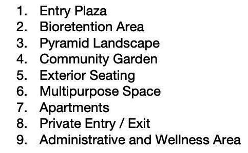
8 CASE STUDY NO. 1 IVY SENIOR APARTMENTS Designing for Zero Carbon: Volume 2 IVY SENIOR APARTMENTS — FLOOR PLANS SITE AND GROUND FLOOR PLAN 0 10 20 30 50 100 FT 0’ 2’ 4’ 8’ R 0’ 2’ 4’ 8’ NORTH 10 A B B C C
Laundry
Mech.
10.
/
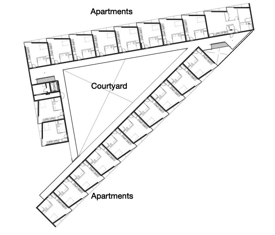
9 IVY SENIOR APARTMENTS CASE STUDY NO. 1 Designing for Zero Carbon: Volume 2 SECOND FLOOR PLAN THIRD FLOOR PLAN A A B B C C A A C C B B
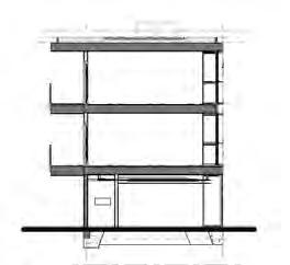
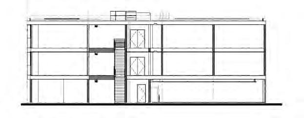
10 CASE STUDY NO. 1 IVY SENIOR APARTMENTS Designing for Zero Carbon: Volume 2
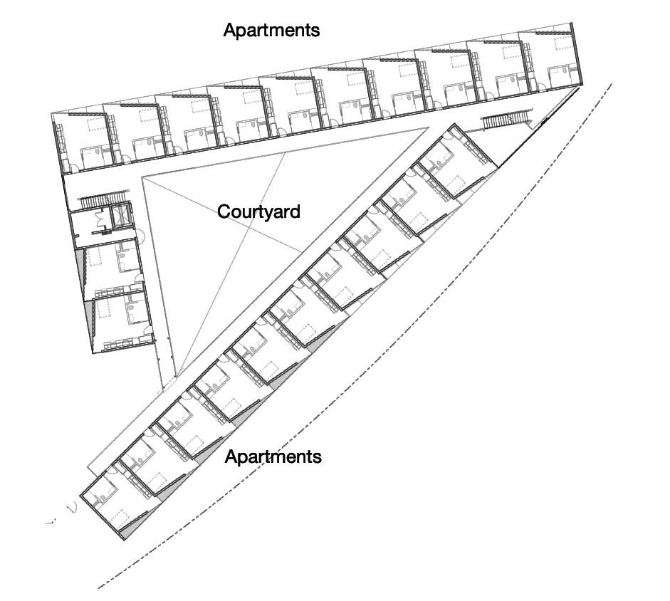
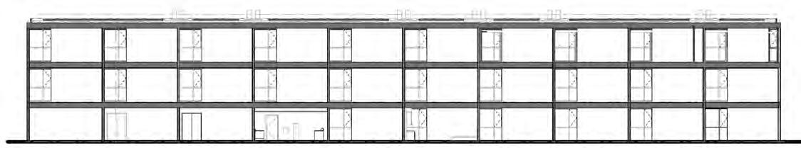
A
SECTION A -
SECTION B - B
IVY SENIOR APARTMENTS — BUILDING SECTIONS 0 10 20 30 50 100 FT 0’ 2’ 4’ 8’ R 0’ 2’ 4’ 8’
SECTION C - C
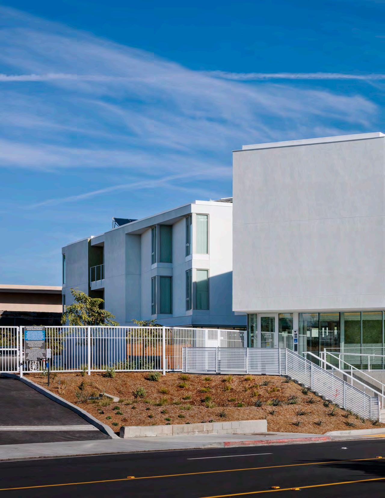
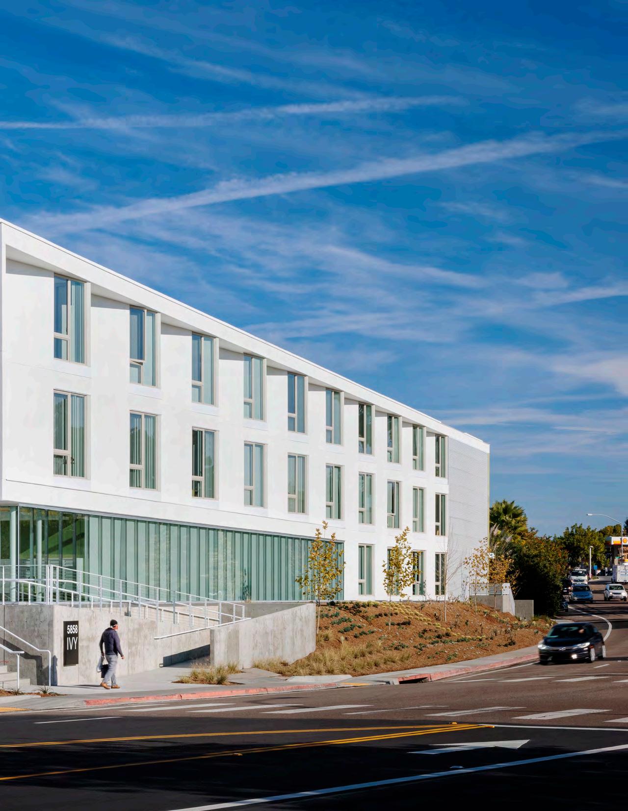
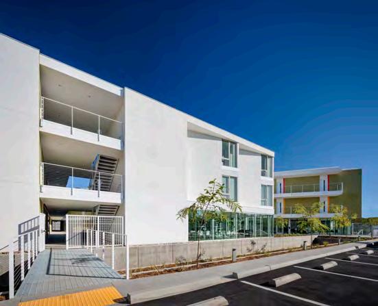
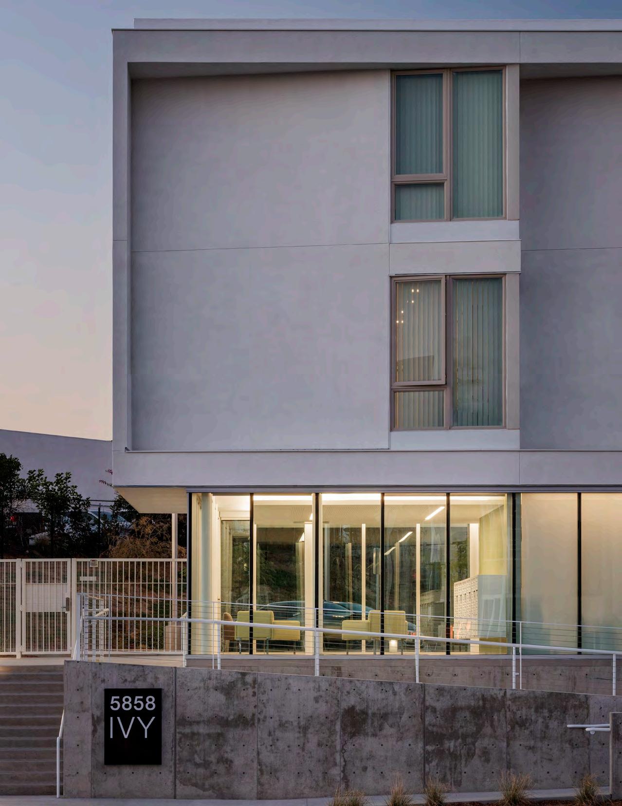
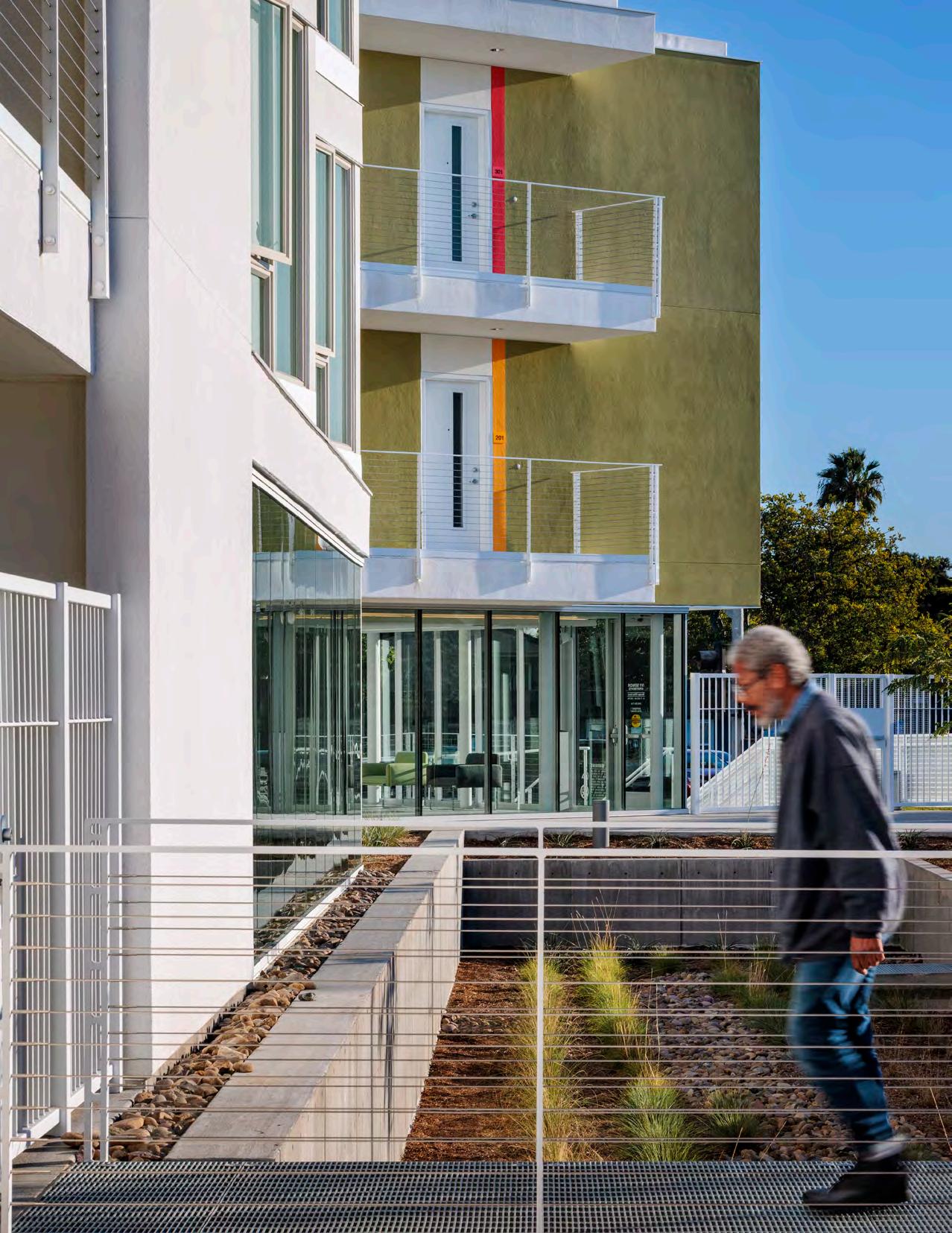
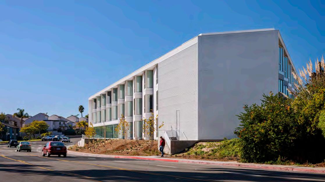
(Right) Entrance to the Ivy Senior Apartments
(Below) Exterior views of apartment building wings. (Photos courtesy of Chipper Hatter)
11
PHOTO: CHIPPER HATTER
Site landscaping provides a visual buffer between the new building and the shopping center activities. A bioretention area for storm water runoff was actually accommodated adjacent to the parking area.
Building Envelope – Insulation and Windows
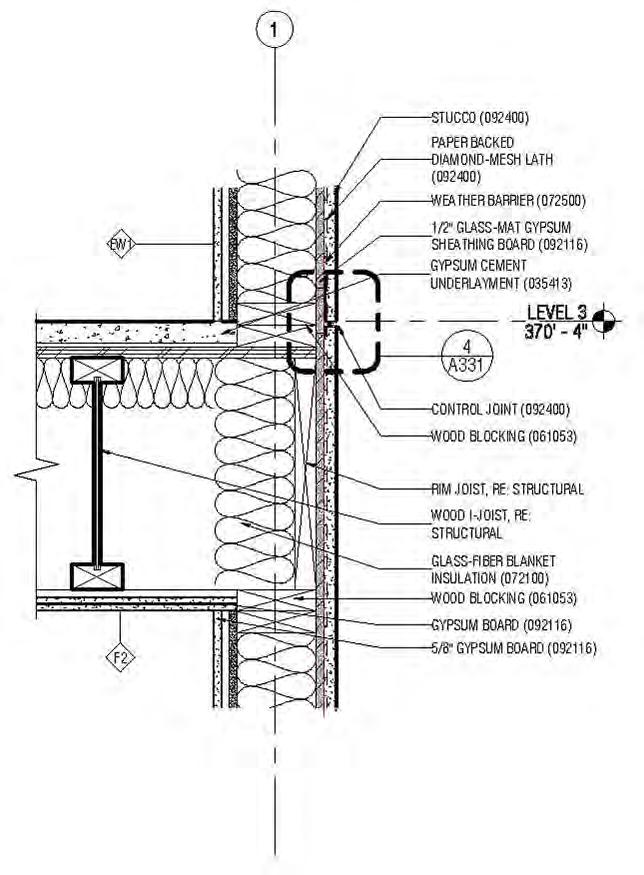
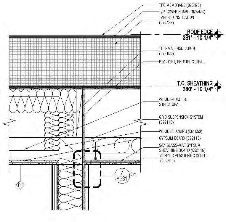
The three-story building meets the basic requirements of California Title-24 code with regard to the insulating characteristics of the building envelope. The typical exterior wall uses conventional 2 x 6 wood framing with 5.5”-thick fiberglass batt insulation, for a U-value of 0.069 (R-21). The roof uses fiberglass batt insulation in the interstitial spaces of the roof framing and a tapered insulation board above the framing, for a total U-value of 0.026 (R-30). The concrete floor slab is uninsulated and has no edge insulation.
Windows and store-front glazing used in the exterior walls also satisfy the minimum requirements of California Title-24 Part 6 energy code, with a U-value of 0.27 for the double-glazed systems.
12 CASE STUDY NO. 1 IVY SENIOR APARTMENTS Designing for Zero Carbon: Volume 2
TYPICAL DETAIL — Corridor Wall Intersection with Roof TYPICAL DETAIL — Intermediate Floor at Exterior Wall Exterior Exterior Interior Interior
Building Envelope – Airtightness
No special measures were taken to ensure airtightness other than conventional details to reduce air infiltration heat losses. No blower door test7 was used to measure airtightness and establish a benchmark number (ACH50).
Heating, Ventilating and Cooling Systems

A ductless mini-split system is used for space conditioning in the apartments. There is an outdoor unit located directly overhead on the roof, which is the condenser part of the heating/cooling
7 For a discussion of this method of testing airtightness in buildings, see p. 12, Zero Net Energy Case Study Homes - Volume 1, available as a free PDF at https://calbem.ibpsa.us/wp-content/ uploads/2020/04/ZNE-Case-Study-Homes-Volume-1.pdf. See also https://www.energy.gov/energysaver/blower-door-tests

13 IVY SENIOR APARTMENTS CASE STUDY NO. 1 Designing for Zero Carbon: Volume 2
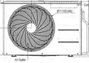
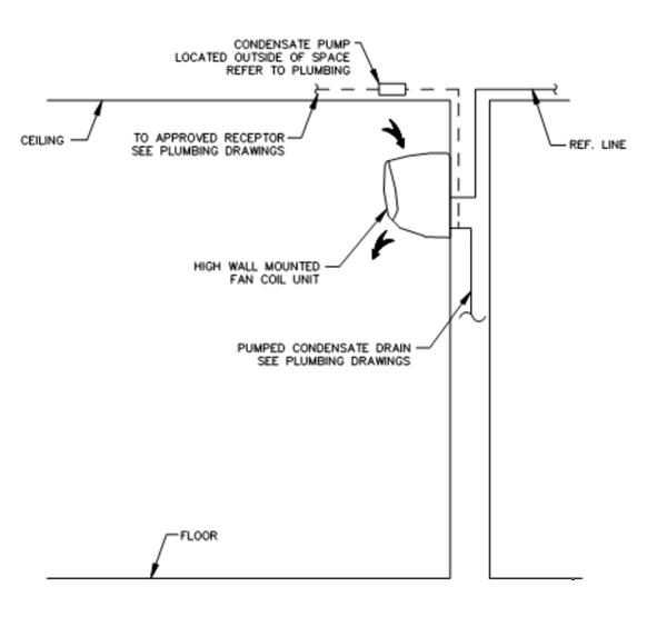
AIR INTAKE AIR OUTLET TO ROOM HIGH WALL-MOUNTED FAN COIL UNIT ROOF-MOUNTED OUTDOOR NON-VRF CONDENSING UNIT
(Left) Equipment diagram for the ductless mini-split heat pump system used for heating and cooling individual apartments.
cycle, and one or more indoor units in the occupied space, which consists of coils through which refrigerant circulates to a fan coil.
This ductless system works well in these apartments, where space is at a premium and ceiling height is not diminished by the need to create soffits for duct space. The apartments have relatively high ceilings without adding cost by increasing the floor-to-floor height. Higher ceilings also allow taller windows, resulting in good daylight penetration into the units.
The heat pump has the capacity to produce up to 12,000 Btu/hr at the fan coil in each of the 52 studio apartments. For the on-site manager’s two-bedroom apartment, two additional fan coils of 9,000 Btu/hr capacity each are located in the additional bedroom spaces.
The remaining spaces in the building, namely the reception area/mailroom, multipurpose room, administrative office, health service rooms and the laundry room, use ducted-air heat pump systems. These are better suited to the more complex floor plans with a variety of uses.
Electric heat pumps are now prescriptively required by the 2022 California Title-24 energy code for either space heating or hot water in multifamily housing in lieu of gas furnaces or gas water heaters. Projects may still install the gas option, but would have to demonstrate compliance through the performance approach by improving the energy efficiency of other building features in order to comply.
14 CASE STUDY NO. 1 IVY SENIOR APARTMENTS Designing for Zero Carbon: Volume 2
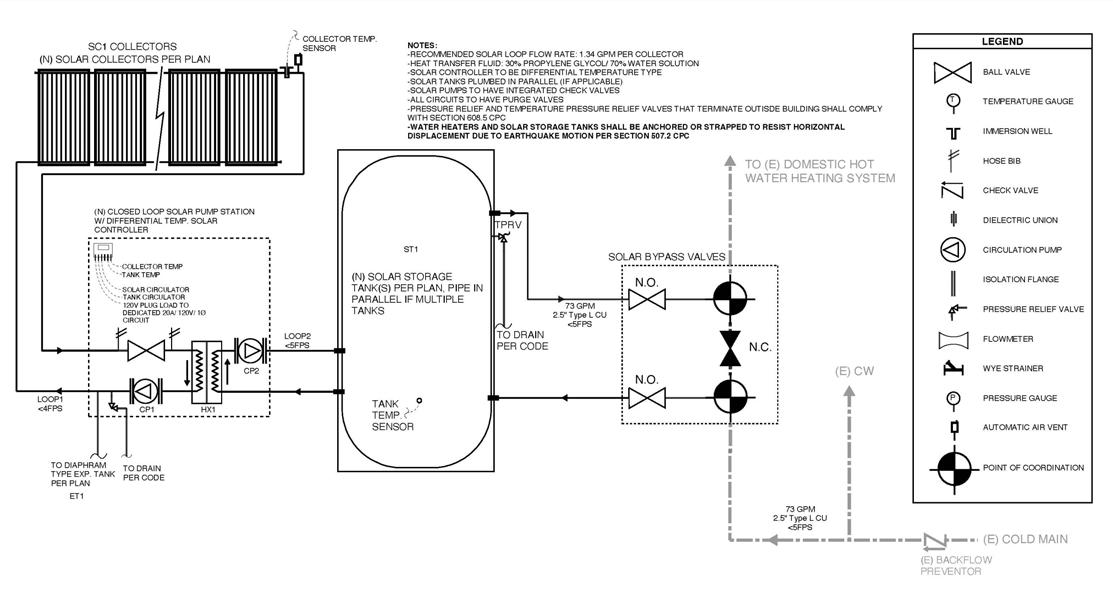
(Below) Plumbing diagram for the Central Heat Pump Water Heating System used at the Ivy Senior Apartments
Domestic Hot Water System
A central heat pump water heater (HPWH) system is used to heat all the domestic hot water (DHW) for the complex, including all apartments, administrative spaces and shared facilities. (See system diagram on the previous page.)
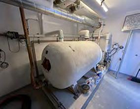
The water is preheated using a solar thermal system, which was required for the prescriptive path of the California Title-24 energy code for multifamily housing at the time this project was approved (2019). The preheated water is then circulated to the two HPWH units located outside the water heating room on the ground floor. The heat pumps raise the temperature of the water and direct it into the large hot water storage tank. The water distribution system is a typical central water heating system, with the main distribution piping installed first horizontally in the ceiling of the first floor, then vertically to the apartments above.
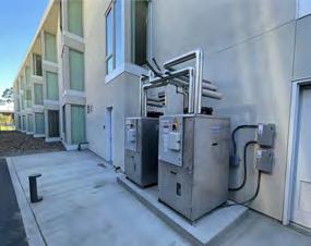
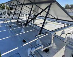
The solar thermal panels (shown in Photo 1 above) actually utilize a “working fluid” that transfers the captured solar heat in the panels to a potable water supply via a heat exchanger. The heated water is circulated to a dedicated solar storage tank (shown in Photo 2 above), though it is not fully at the necessary temperature for use in the building. This water source, however, serves as an effective preheated supply for the central system.
Two heat pumps (shown in Photo 3 above) are used for the water heating system to ensure a redundancy in the supply system. These large pieces of equipment must be located outside and produce a certain amount of noise during operation (85 dBA). The water heating room was therefore located as far as possible from the apartments, which consequently positioned the heat pumps on the back side of the building complex, where the noise would be least intrusive.
Appliances
Typical electric appliances are used in each apartment, including an ordinary electric range. Induction ranges were not selected because of comparative cost and lack of familiarity with this type of appliance among this particular occupant group.
The common laundry facility is outfitted with conventional electric dryers with direct venting to the outside, rather than heat pump dryers, which are more energy efficient.
Lighting and Plug Loads
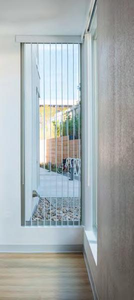
Daylighting design was emphasized for each apartment unit. As noted above, the ceiling height could be kept at a relatively high 9’-2” because no ceiling space is needed for ductwork. The exterior windows for each unit could therefore be set at 8’ tall, which gives much greater daylight penetration into the interior of the units. In addition, light from two sides of the unit is possible because of the windows on the circulation decks (entry sides of the unit). This not only reduces potential glare from the large window, but encourages turning off electric light sources because of the high visual comfort resulting from the good daylighting design.
Another noteworthy amenity is that the infrastructure for electric car charging was installed in the common parking area, so that the project is “EV-car ready”. The car-charging units can be attached to the designated locations near each parking space, providing this service to staff and visitors.
Battery Storage
None included or planned for future installation.
15 IVY SENIOR APARTMENTS CASE STUDY NO. 1 Designing for Zero Carbon: Volume 2
1 2 3
(Above) Tall windows could be used in all units because of the relatively high ceilings, providing good daylight penetration to the interiors of the units.
16
PHOTO: CHIPPER HATTER
Renewable On-Site Energy Supply
Solar Thermal System
The solar thermal system described in the previous section was actually required to be part of the DHW system at the time of this project’s building permit application (2019) by the terms of the grant from the California Solar Initiative (CSI), administered by the California Public Utilities Commission (CPUC). This requirement is no longer in effect, having been removed with the adoption of the new Title-24 energy code in 2020. It was deemed to be more efficient to simply apply electrical energy directly to the preheating elements and make better use of limited roof space for solar PV panels.
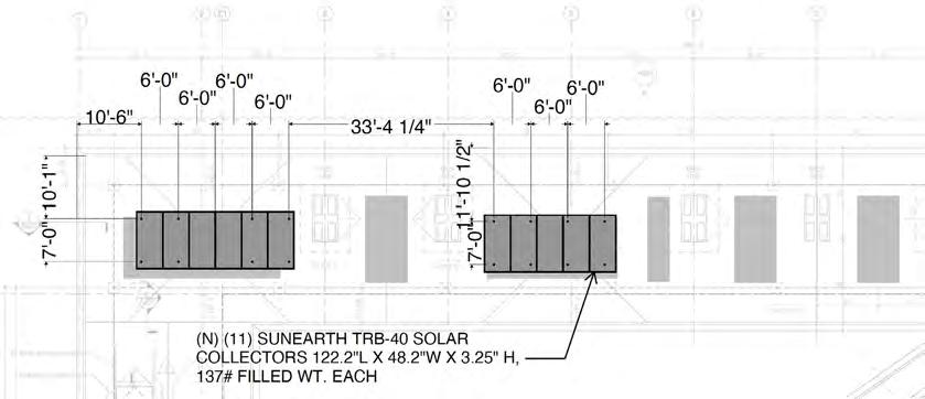
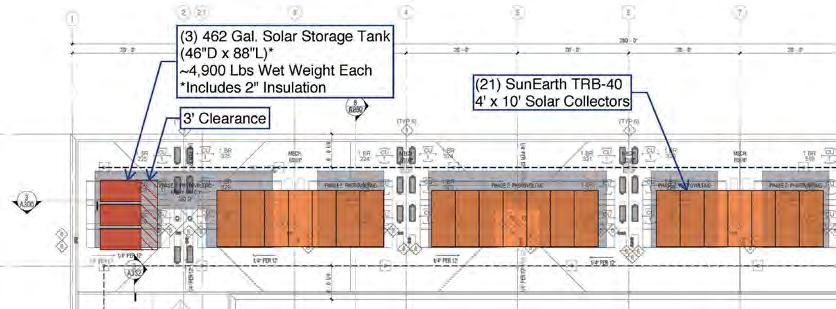
The system consists of eleven SunEarth TRB-40 solar thermal collectors (4’x10’) circulating heated water to the solar hot water storage tank. Originally designed as a 20-panel system, calculations showed that the preheated water temperature would be too high, reducing the boiler efficiency and causing the solar thermal system to be shut off approximately 40% of the operating time. Reducing the system to 11 panels balanced the system and optimized performance, incidentally opening up more roof space for the solar PV panels.
PRELIMINARY DESIGN
FINAL DESIGN (AS BUILT)
KEY: PLAN LOCATIONSOLAR THERMAL PANELS
17 IVY SENIOR APARTMENTS CASE STUDY NO. 1 Designing for Zero Carbon: Volume 2 16
(Left) Solar thermal panels system design and layout on northwest roof, preliminary (top) and final design (bottom).
Solar Photovoltaic System


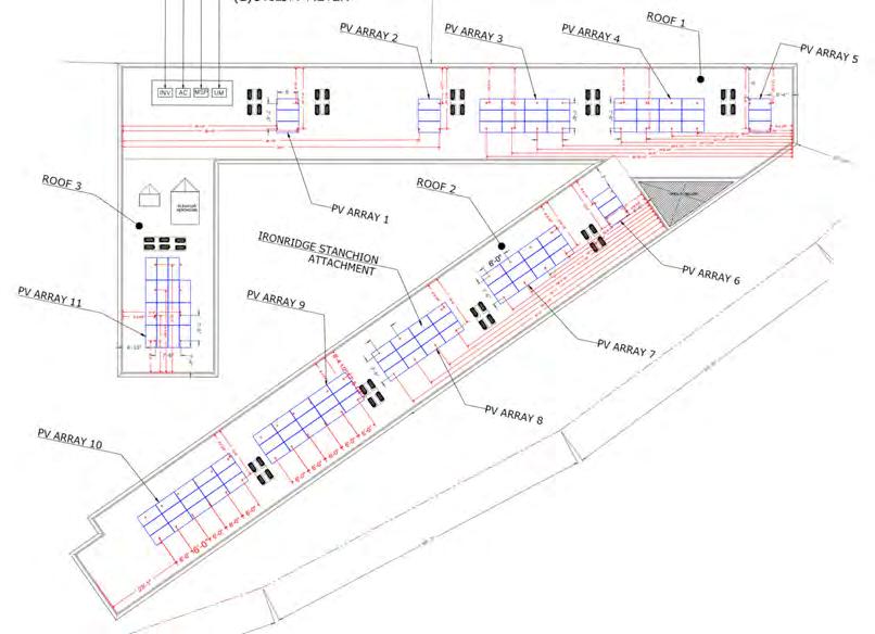
The solar photovoltaic system was designed to fit on the remaining roof space after the solar thermal requirements were met. Several alternative designs were proposed and specified by the design team, but supply chain problems in 2020 led to a new specification for the PV panels at the time scheduled for installation. The final installation proved to be more efficient because of the availability of a bifacial module, which has greater output and a slightly lower cost.
18 CASE STUDY NO. 1 IVY SENIOR APARTMENTS Designing for Zero Carbon: Volume 2
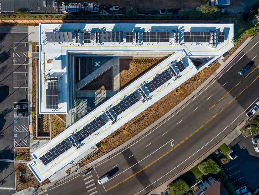
(Right) Drone photograph of the final installation of the solar panels on the roof of the Ivy Senior Apartments. In addition to the solar PV panels, the 11 solar thermal panels are visible in the upper left of the photo.
(Right) Diagram of the installed PV system, consisting of 105 Trina Commercial modules, Duomax Twin, 410 watt each, for a total installation of 43.05 kW(DC)
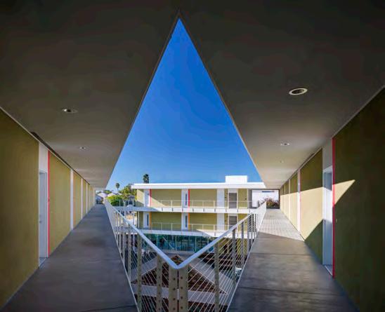
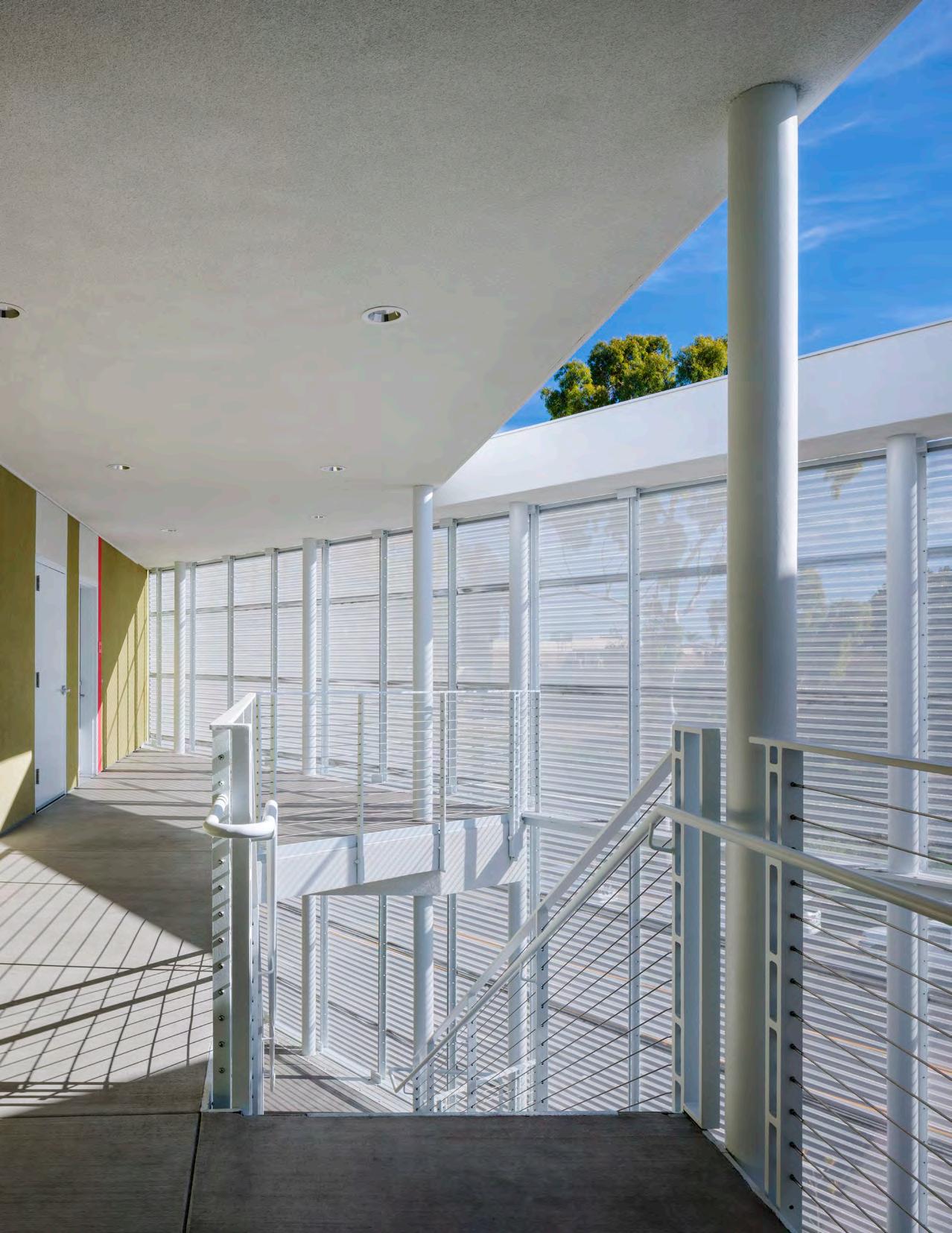
(Opposite Page) Interior view at northeast corner exterior stair and roof above.
19
PHOTO: CHIPPER HATTER
255,000 kWh/year
Modeled EUI = 22.0
Design Analysis: Optimizing Zero-Carbon Design
Design Analysis: Embodied Carbon
An embodied carbon analysis was not undertaken because the type of structure and construction materials to be used in the new building were standard wood-frame and cost effective, so that low embodied carbon content was expected for the eventual design solution.
Design Analysis: Energy Modeling and Operational Carbon
As part of the Title-24 energy code compliance, an energy analysis was done using the Californnia Building Energy Code Compliance Software - Residential (CBECC-Res). The result for the total annual (electrical) energy use for the entire building is 255,000 kWh, or an EUI equal to 22.0 (kBtu/sq.ft. per year).
The energy provided by the on-site solar thermal and solar PV systems was also modeled. The energy produced by the solar thermal system was predicted to be 14,462 kWh per year and, using PV-Watts8, the contribution of the solar PV system was estimated at 73,280 kWh. Together, the two renewable energy systems would be expected to reduce the annual energy use to 167,147 kWh, a reduction of 34%.
8 See: https://pvwatts.nrel.gov/index.php
Modeled Annual Energy Use (CBECC-Res Software)
20 CASE STUDY NO. 1 IVY SENIOR APARTMENTS Designing for Zero Carbon: Volume 2 17
PHOTO: JEREMY BITTERMANN / JBSA
Energy Performance and Operational Carbon: Post-Occupancy Measurement
Energy Use — Post-Occupancy Measurement
The project reached full occupancy in November 2021, making it possible to obtain one full year of energy performance data from the public utility. Combined with the monitored production data of the two solar energy systems, a direct comparison of the measured data with the modeled results would be possible. Unfortunately, the solar thermal system was not monitored during this first year, so the measured data of the total electric energy offset by this on-site renewable energy system is missing that one small component (likely only a 5% effect overall).
Comparison with Energy Modeling
The measured annual energy use based on the utility bills for the first year of full occupancy (December 2021- November 2022) was 185,451 kWh. This compares to the design modeling and estimation of 167,147 kWh, which includes the estimated reductions due to the two solar energy systems.
The actual performance of the building without these reductions is equal to the sum of the monthly utility bill totals for the 12-month periood and the energy supplied by the two solar energy systems, which offset a portion of the building’s energy use. During this period, the solar PV system produced 81,937 kWh, slightly higher than that predicted using PV-Watts. Therefore, the total measured energy use for the building was 267,388 kWh over that 12-month period, plus that small amount offset by the unrecorded energy supplied by the solar thermal system.
If the latter is assumed to be approximately equal to that estimated during the design phase, namely 15,000 kWh, then the building consumed close to 282,000 kWh during the 12-month period, 12/2021 - 11/2022. This converts to an actual EUI for the building of 24.4 (kBtu/sf-yr). The measured performance overall is therefore slightly higher than that predicted by the energy modeling, with the solar PV system actually providing more electric energy than estimated.
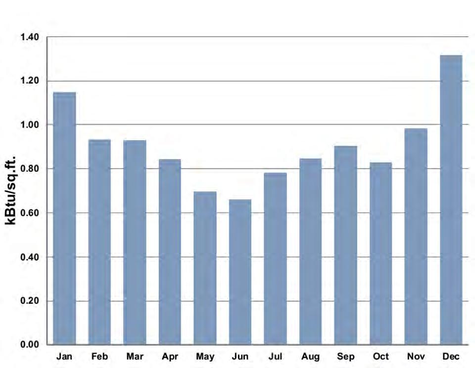
Energy Production versus Energy Use
Both the building overall net energy use (the energy use from the utility grid) and the energy produced by the solar PV system were metered on a monthly basis for the 12-month period, 12/2021 - 11/2022. The Base Building Energy Use was determined as the sum of the net energy from the utility grid, the on-site energy produced by the solar PV system plus 5% to account for the energy provided by the solar thermal system.
The results are shown in the graph on the next page.
21 IVY SENIOR APARTMENTS CASE STUDY NO. 1 Designing for Zero Carbon: Volume 2
Solar Photovoltaic System Performance (2021-2022)
Solar Photovoltaic System Performance (2021 - 2022)
Post-Occupancy: Observations and Conclusions
Post-Occupancy: Lessons for Future Affordable Housing Projects
Wakeland expressed great satisfaction with the all-electric nature of this project, particularly for those serving low-income seniors. All of the company’s future projects will be all-electric as a result. The project proved to be cost-effective in terms of both first costs and operation/maintenance costs, both of which must be considered together since Wakeland also manages the completed project.
Post-Occupancy: Future Planning (Battery Storage and EV Charging)
No accommmodation was made for the future installation of an array of batteries for electric load management or resiliency in case of power outages. Rate structures where peak load rates are significantly higher than off-peak rates will likely have a significant impact on operating cost, particularly in all-electric projects. Planning for such load management capability seems advisable for future projects.
Electric vehicles (EVs) and plug-in hybrid eletric vehicles (PHEVs) will be the only new automobiles sold in California in 2035 by legal mandate.9 In anticipation of this, Wakeland did install the infrastructure for car-charging stations in the staff and visitor parking lot.
Post-Occupancy: Embodied Carbon Assessment
As noted above, an embodied carbon analysis was not undertaken because adequate analytical tools were not available at the time this project was designed (2018). Future projects may consider alternative structural systems that minimize the embodied carbon, such as mass timber, to determine the cost effectiveness of that possible option.
9 Executive Order N-79-20 and California Air Resources Board (CARB) 2022 Advanced Clean Cars II Rule.
22 CASE STUDY NO. 1 IVY SENIOR APARTMENTS Designing for Zero Carbon: Volume 2
0 2,000 4,000 6,000 8,000 10,000 12,000 14,000 16,000 18,000 20,000 22,000 24,000 26,000 28,000 30,000 Dec Jan FebMar Apr May JunJul Aug Sep Oct Nov kWh
2021 2022
Energy Use (Base Building) Energy Production (PV System)
23
PHOTO: CHIPPER HATTER
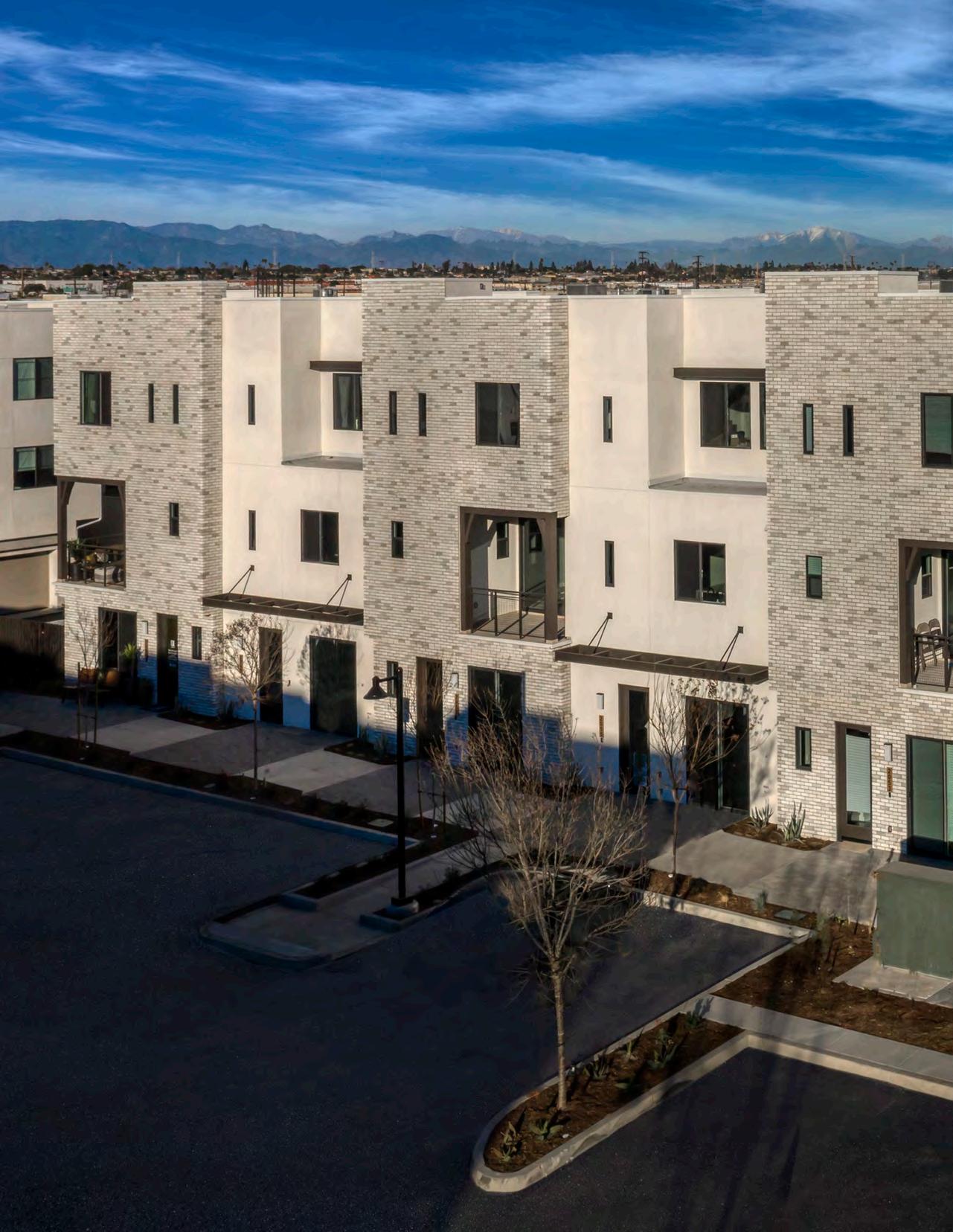
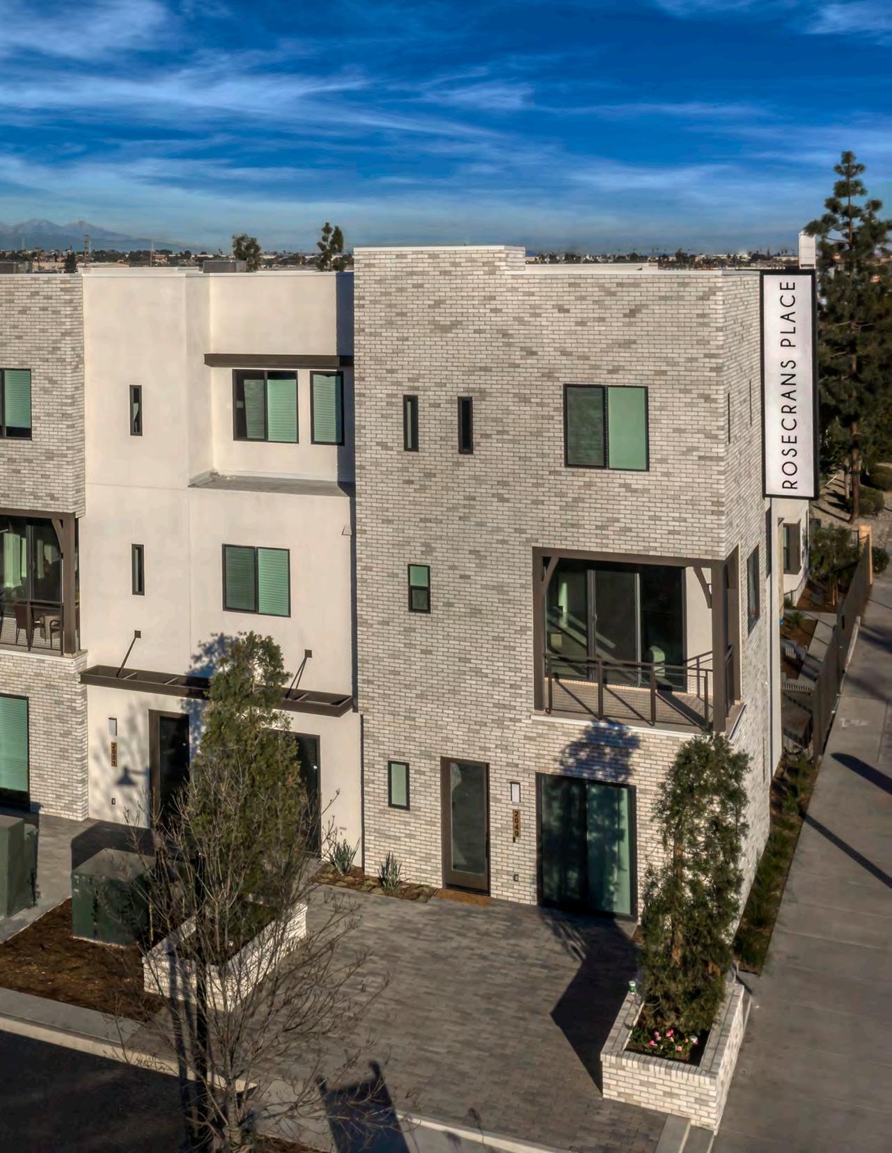
Rosecrans Place
CASE STUDY NO. 2 24
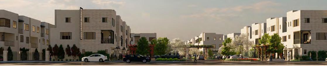
25
RENDERING: MICHAEL BAST GRAPHICS, INC.
Rosecrans Place Case Study No. 2
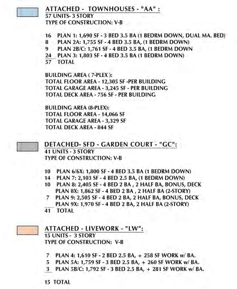
Data Summary
Project Type: Market-Type Units For Sale (New)
Location: Gardena, CA
California Climate Zone: 8
Gross Floor Area: 113,958 sq.ft. (Multifamily units only)
Fully Occupied: March 2023
Modeled EUI (Site): 10.9 kBtu/sq.ft. per year (Multifamily units only)
Measured EUI (Site): Not yet available
On-Site Renewable Energy System Installed: 28.8 kW (DC) Solar PV (Multifamily units only)
On-Site Storage Battery: None
Measured On-Site Energy
Production: Not yet available
Owner/Client
Joint Venture:
G3 Urban, Gardena
Borstein Enterprises, Los Angeles
Design Team
Architect:
Angeleno Associates, Inc., Santa Ana
Mechanical, Electrical and Plumbing Engineering:
Gouvis Engineering, Irvine
Energy Modeling:
Gouvis Engineering, Irvine
Landscape Architect:
STB Landscape Architecture, Redlands
General Contractor:
G3 Urban, Gardena
Solar Contractor:
Scott Construction Specialties, Wildomar
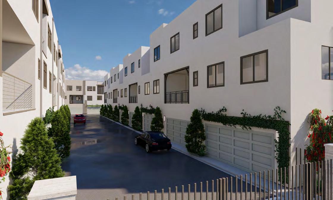
Another type of multifamily residential housing is new townhomes or apartments that are offered for sale as condominiums. This market rate housing is produced by for-profit developers and, because of its speculative nature, is driven by issues of marketability, initial cost and architectural appeal. For all-electric projects of this type, initial cost is a primary consideration, but marketability also dictates the amount of profit on the project, sometimes to a greater extent. An all-electric design and the associated eventual zero-carbon characteristic can minimiize first cost as well as increase marketability, as this particular case study demonstrates.
Background
The developer of this urban-infill project, G3 Urban, has specialized in all-electric multifamily projects since it was founded in 2016 by Herb Gardner, who had been involved in speculative homebuilding for more than 25 years before that. Joined by other family members who had worked with him at his previous homebuilding firms, Mr. Gardner emphasizes “green” design features in his work. The new firm is committed to producing mainstream housing that is designed to be energy efficient, employing “smart” technologies and free of on-site fossil fuel energy sources. This is featured in their marketing of the townhomes, which are called “solar all-electric homes” and feature EV readiness as well.
Another key member of the project team was Borstein Enterprises, which is the equity partner for G3 Urban on all their projects. They secured the financing for the purchase of the land, construction funding and operational cost overhead. Borstein Enterposes also advised on the marketing strategy, which proved to be highly successful, including the types of units and the physical design of the project itself.
The developer has found that first costs are generally less when gas does not have to be brought to the site or if gas lines are not installed in the Type-5 wood frame wall construction. The initial project cost was in fact less in each of three projects built in the city of Gardena compared to the estimated cost with gas utilities, including the project that is the subject of this case study.
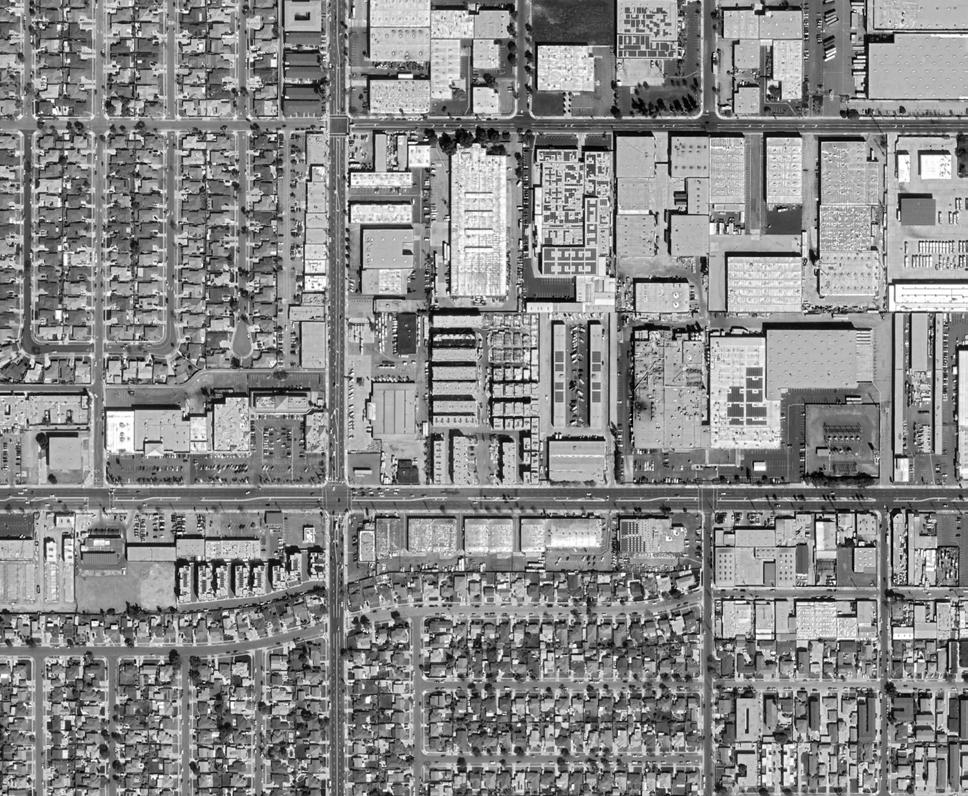
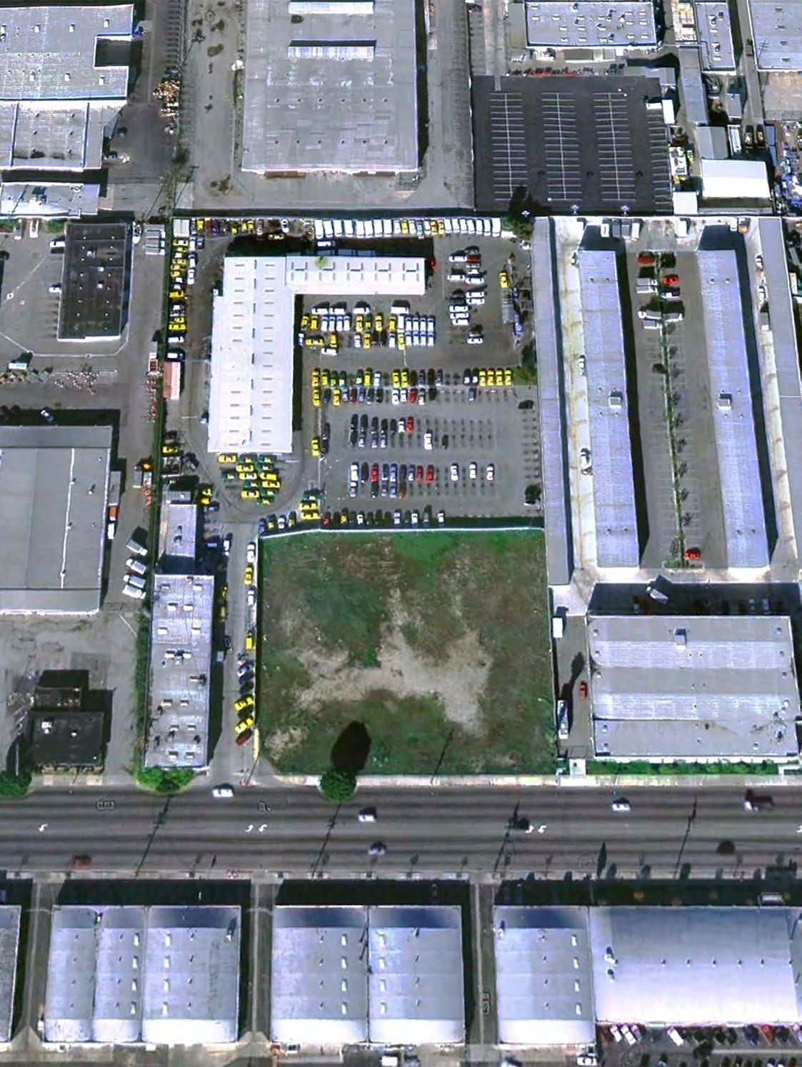
The Rosecrans Place site became available in 2018 and was a former warehouse site for parking and servicing taxicabs. The site was the right size to develop the number of housing units required for a feasible investment as a developer. This size would also allow the development of enough units to make the creation of a homeowners association feasible, as well as the development of landscape features and shared site amenities that would prove attractive to potential buyers.
Set in a larger area just south of downtown Los Angeles, this area had been in gradual decline as a residential suburb for the past five decades. Recently, young residents have been attracted to the area by the lower property costs, proximity to downtown and the appearance of new multifamily residential infill projects such as Rosecrans Place. As evidence of the growing desirability of this location, and also an indicator that all-electric design is not an impediment to potential buyers, all of the townhomes were sold before construction commenced, a measure of success for any developer.
26 CASE STUDY NO. 2 ROSECRANS PLACE Designing for Zero Carbon: Volume 2
27 ROSECRANS PLACE CASE STUDY NO. 2 Designing for Zero Carbon: Volume 2
Rosecrans Place - General Vicinity Plan
Rosecrans Avenue
W 135th Avenue
Van Ness Avenue
28 CASE STUDY NO. 2 ROSECRANS PLACE Designing for Zero Carbon: Volume 2
Design Process and Low-Energy, Zero-Carbon Design Strategies
As developer and general contractor for the project, G3 Urban assembled the design team based on previous experience with similar projects. Planning began in 2018, when the site was purchased. The design was developed and the permits secured, with construction beginning on the first phase of the project in 2019.
Building Program
The building program was largely dictated by the site constraints and the financial considerations around the marketing and sale of the units. To target the potential young buyers working in the general area, Borstein advised building three distinct housing types: live-work townhomes (mixed residential/commercial), regular townhomes (all residential) and some freestanding single-family units.
The addition to the program mix of the live-work units, where the residential space in the unit would sit above a ground-floor commercial space, was seen as a way to increase purchase options and speed up absorption of the project units in advance of construction. Also, city planning regulations for this type of unit are generally somewhat less prescriptive than residential-only and can be marketed with a less refined finish. Therefore, they generally can be built at lower cost than comparably-sized residential units, in addition to their appeal as unconventional living spaces—all attractive to modern young buyers.
The developer team felt that there also would be buyers interested in single-family detached units rather than the townhouse designs. These could be added to the development in a fairly dense manner using the common architectural design language of the project. This departure from the conventional, less-dense suburban model for single-family detached houses was also seen as appealing to the target market of younger buyers.
The net result, after intensive design study, was a program resulting in 113 units composed of 57 three-story attached townhouse condominiums, 15 live-work condominiums and 41 detached houses. The overall final site plan is shown on the following pages, along with the detailed project data for each type of multifamily unit and the single-family detached housing.
The initial phase of construction, completed in the fall of 2021, consisted of the live-work units and a formal entry gateway to the second and third phases of the development to be built on the remaining portion of the site. Most of the multifamily units were completed in the second phase of construction and occupied in 2022. The remaining buildings are scheduled for completion in the spring of 2023 in the third and final phase.
Site Constraints
The site is surrounded on three sides by warehouses and self-storage facilities. No trees or nearby built objects of any size obstruct the solar access to the rooftops. This was an important consideration in the site evaluation.
(Opposite Page) Project site in June 2018, at the time of the site acquisition by the developer.
29 ROSECRANS PLACE CASE STUDY NO. 2 Designing for Zero Carbon: Volume 2
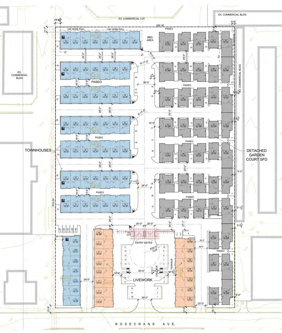
30 CASE STUDY NO. 2 ROSECRANS PLACE Designing for Zero Carbon: Volume 2 ROSECRANS PLACE — SITE PLAN NORTH 0 10 50 100 FT
BLDG 4
BLDG 2
See pp. 32-33 (following) for detailed floor plans of these townhouses.
31 ROSECRANS PLACE CASE STUDY NO. 2 Designing for Zero Carbon: Volume 2
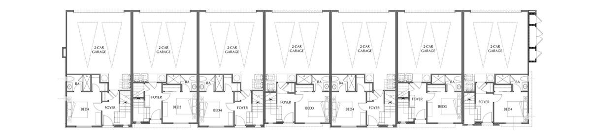
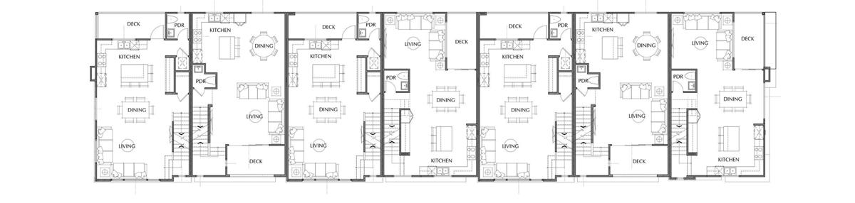
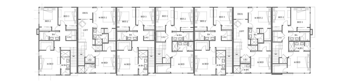
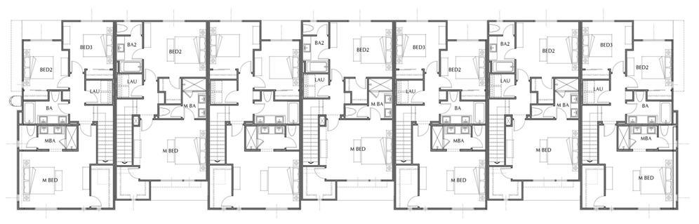
32 CASE STUDY NO. 2 ROSECRANS PLACE Designing for Zero Carbon: Volume 2 FIRST FLOOR PLAN 0 5 10 20 40 FT 0’ 2’ 4’ 8’ R A A TOWNHOUSE CONDOMINIUMS — BUILDING 4 FLOOR PLANS SECOND FLOOR PLAN THIRD FLOOR PLAN NORTH PLAN 3B PLAN 1A PLAN 3A PLAN 2A PLAN 3A PLAN 1A PLAN 2B
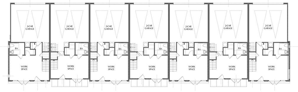
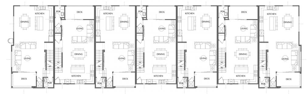
33 ROSECRANS PLACE CASE STUDY NO. 2 Designing for Zero Carbon: Volume 2 LIVE/WORK CONDOMINIUMS — BUILDING 2 FLOOR PLANS SECOND FLOOR PLAN FIRST FLOOR PLAN THIRD FLOOR PLAN NORTH 0 5 10 20 40 FT 0’ 2’ 4’ 8’ R B PLAN 5B PLAN 4A PLAN 5A PLAN 4A PLAN 5A PLAN 4A PLAN 5C
PORCELAIN TILE
R-38 PORCELAIN TILE R-19
Building Envelope – Insulation and Windows
The three-story buildings are conventional wood-frame construction, using 2 x 6 framing for the walls and truss-joist floor and roof assemblies. Insulation levels meet or exceed the Title-24 requirements for the building envelope, with R-19 walls and R-38 roofs as the standard. The concrete ground-floor construction is typical uninsulated slab-on-grade with no edge insulation. (See typical wall section diagram at left.)
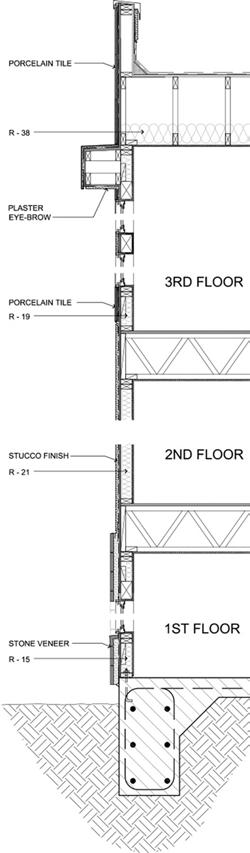
Windows used in the exterior walls also satisfy the minimum requirements of California Title-24 code, with a standard double-glazed product.
Building Envelope – Airtightness
No special measures, such as a Blower Door test1, were taken with this new construction to ensure airtightness other than “good practices” to control air infiltration heating/cooling energy losses.
Heating, Ventilating and Cooling Systems
STUCCO FINISH STONE VENEER
PLASTER EYE-BROW R-21 R-15
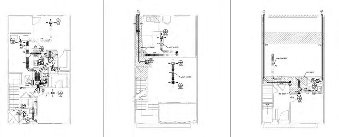
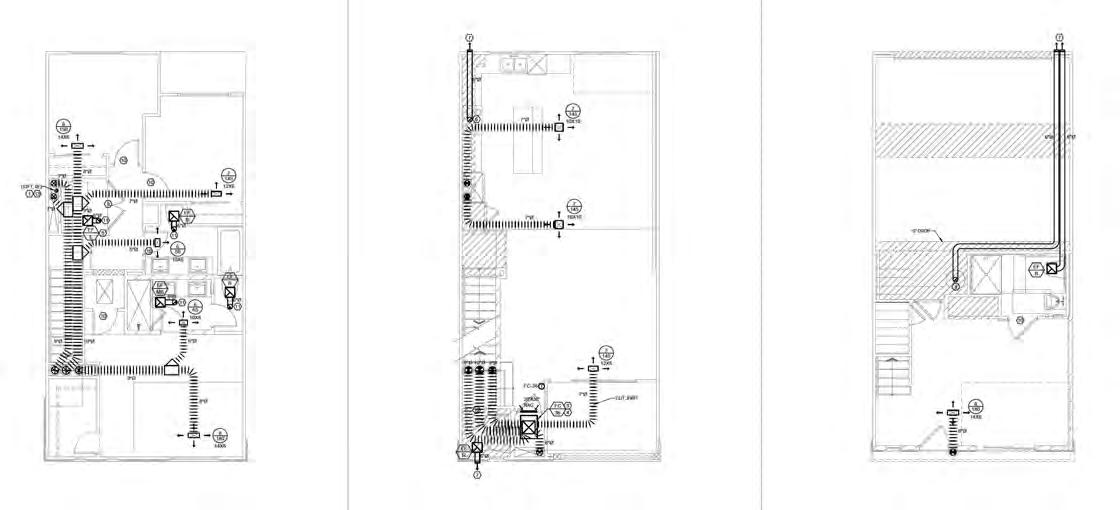
Each residential unit is provided with its own ducted-air heat pump system. The condenser unit is mounted on the flat roof of each unit and is connected to a fan coil unit just below the roof level. Refrigerant circulates between these two parts of the heat pump, providing either heated or chilled coils at the fan coil to heat or chill the air being circulated throughout the unit. The conditioned air is supplied to and returned from the various rooms and spaces in the house through a conventional duct system, as shown in the diagrams for a typical townhouse and live-work design on the opposite page.
Air exhausted is exhausted from from bathrooms and kitchens by conventional means. No energy recovery ventilator (ERV) is used, which would recover some energy via a thermal exchange process between incoming fresh air and conditioned air being exhausted.
Domestic Hot Water Systems
The heat pump also provides heating for the domestic hot water supply in the unit, known as a “hybrid heat pump” application. The heated water is stored in a tank, usually located in a utility closet. Since the Californnia energy code does not allow “tankless” electric water heaters, this is an additional space requirement for all-electric residential units, albeit a small one.
1 For a discussion of this method of testing air-tightness in buildings, see p. 12, Zero Net Energy Case Study Homes - Volume 1, available as a free PDF at https://calbem.ibpsa.us/wpcontent/uploads/2020/04/ZNE-Case-Study-Homes-Volume-1.pdf. See also https://www.energy. gov/energysaver/blower-door-tests.
34 CASE STUDY NO. 2 ROSECRANS PLACE Designing for Zero Carbon: Volume 2
(Above) Typical wall section used at multifamily buildings.
THIRD
SECOND FLOOR PLAN
FIRST FLOOR PLAN
35 ROSECRANS PLACE CASE STUDY NO. 2 Designing for Zero Carbon: Volume 2
FLOOR PLAN TYPICAL TOWNHOUSE (PLAN 1A) FIRST FLOOR PLAN
THIRD FLOOR PLAN TYPICAL LIVE/WORK (PLAN 5A) 0’ 2’ 4’ 8’ R B 0 5 10 20 40 FT
SECOND FLOOR PLAN
(Below) Mechanical plans for ducted-air heat pump system for typical attached units.
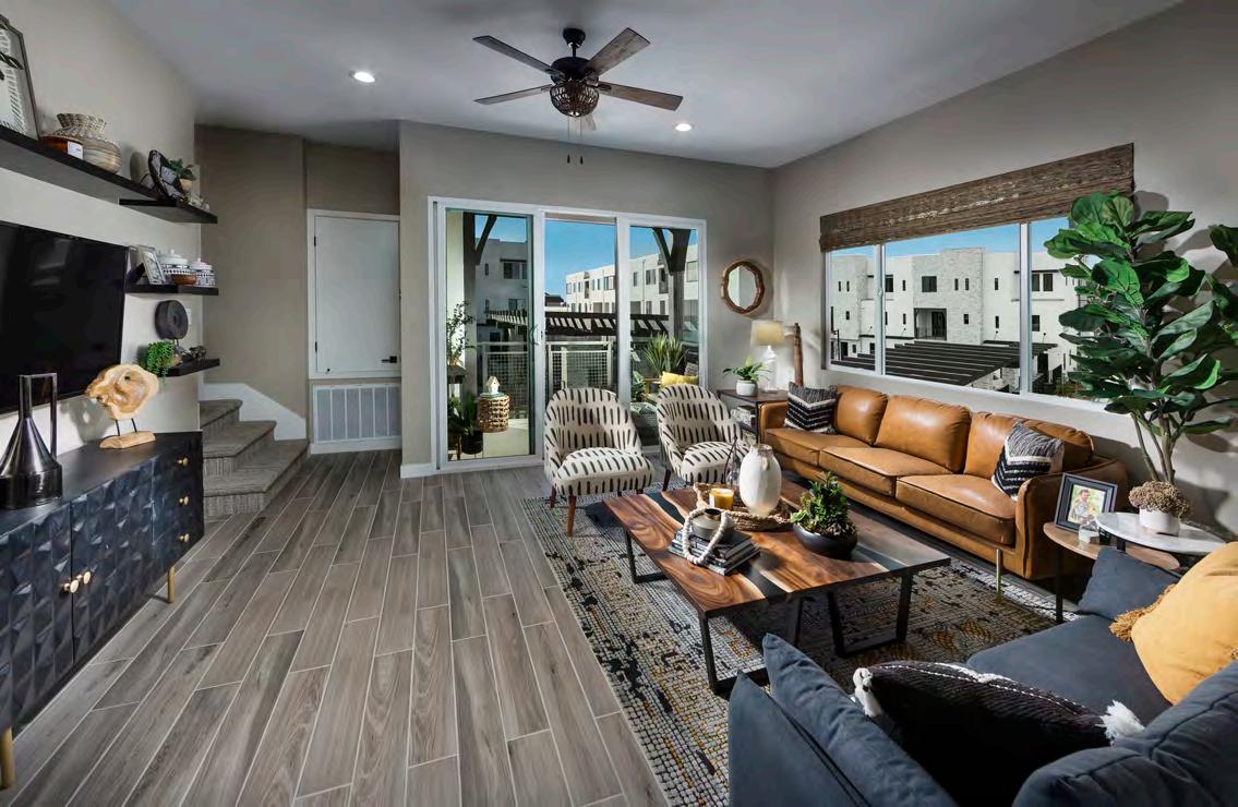
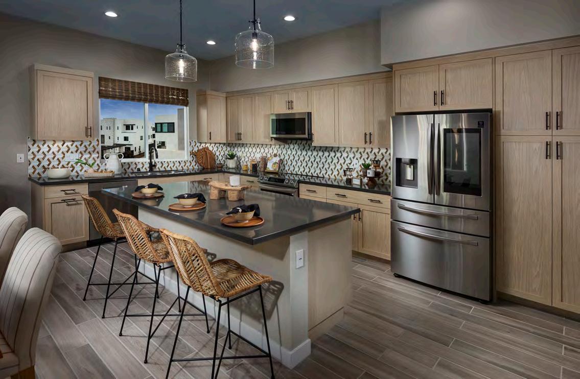
(Opposite Page) Interior views of Live/Work townhouses. Kitchen appliances in the kitchen space (top) include an induction stove.
(Below) Rendered view of the rear of Building 4 townhouses, with two-car garages that are pre-wired for an EV charging unit. (See floor plans on p. 32.)
Appliances
In addition to regular electrical appliances, induction cooktops and electric ovens are used throughout. This presented a minor marketing issue because many consumers still lack familiarity with the advantages of induction cooking. Discussions with potential buyers and referrals to online information, however, proved to be satisfactory.
Other appliances such as electric dryers were selected by the new owners. The advantages of heat pump dryers and condenser dryers were part of the informational package for potential buyers.
Lighting and Plug Loads
Energy-efficient LED lighting is used throughout.
Every unit is equipped with a two-car garage on the ground floor level that is prewired for an electric vehicle charging unit. This is standard with each unit and was seen as having a strong marketing appeal.
Battery Storage
None included
36 CASE STUDY NO. 2 ROSECRANS PLACE Designing for Zero Carbon: Volume 2
RENDERINGS: MICHAEL BAST GRAPHICS, INC.
Designing for Zero Carbon: Volume 2
37 ROSECRANS PLACE CASE STUDY NO. 2
37
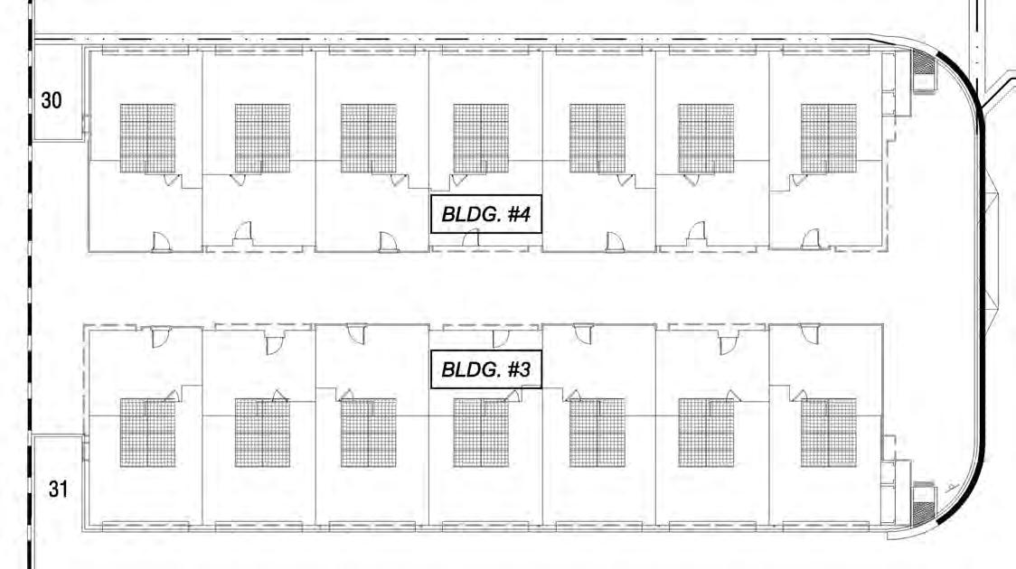
(Below) Plan diagram for the general location of the solar PV arrays on townhouse Building 4 and Building 3. This is typical for all the buildings in the Rosecrans Place project.
Renewable On-Site Energy Supply Solar Photovoltaic System
This entire multifamily portion of the project is featured as a community of “Solar-Powered Townhomes and Live/Work Units”, so the solar photovoltaic system that is part of each basic unit is one of the most attractive selling points for the development. Every unit is equipped with a roofmounted system that generates 2.76 kilowatts, which is estimated to offset about 30% of the anticipated electrical load.
The solar panels are 460w CanadianSolar, Model HiKu High Power Mono Perc Module. There are six panels to each array, which measures 10’-4” x 13’-10” set on a support structure on the flat roof of each building. These solar PV arrays are part of the individual unit but are cleaned and maintained by the Rosecrans Place Homeowners Association (HOA).
The DC power from these panels are converted efficiently to AC power by Enphase IQ8 microinverters.
38 CASE STUDY NO. 2 ROSECRANS PLACE Designing for Zero Carbon: Volume 2
Design Analysis: Optimizing Zero-Carbon Design
Design Analysis: Embodied Carbon
An embodied carbon analysis was not undertaken. There would have been no practical advantage given the nature of the construction, which was all Type-V wood-frame.
Design Analysis: Energy Modeling and Operational Carbon
Energy modeling was undertaken as part of the Title-24 compliance documentation using the California-approved Energy Pro software (Version 7.2). The total annual energy use for each type of unit plan was calculated and Title-24 compliance was confirmed.
In order to assess the expected overall performance of the entire multifamily portion of the project (the standard attached townhouses and the live/work condominiums), the monthly and annual energy use of the individual multifamily units were added together to obtain a project-wide total. This monthly- and annually-modeled energy use is shown in the chart below. The energy use totals do not include the offset provided by the solar PV systems; they represent a measure of the energy efficiency of the buildings alone. Totals by type of load were not calculated, so a breakdown of the modeled energy use for heating/cooling, lighting, plug load and DHW is not available.
Modeled Monthly Energy Use
400,389 kWh/year Modeled EUI = 10.88
39 ROSECRANS PLACE CASE STUDY NO. 2 Designing for Zero Carbon: Volume 2
(EnergyPro v7.2 Software)
Likewise, the solar PV system, the same for each unit, was sized and installed based on the developer’s experience with previous similar projects. The intent was to install a solar PV system that provides roughly 30% of the energy demand of the individual unit. No analysis was done in advance to model the actual expected contribution of the solar PV system to offset this percentage of the energy demand. (Note: as of January 2020, California’s Title 24 requires an estimate of that contribution as part of the documentation of code compliance. This was not a requirement in 2019 when this project was submitted for permit.)
Energy Performance and Operational Carbon: Post-Occupancy Measurement
Energy Use — Post-Occupancy Measurement
The individal units of the project were sold before construction was initiated. The first phase of the project, which included the live-work condominiums and some of the regular townhouse units near the main entry, were therefore all immediately occupied when that phase was completed in early 2022. The final phase of the project was completed in March 2023. The net result is that a full year’s record of utility bills for the individual units was not yet available for comparison with the energy modeling results at the time of printing this book of case studies. It will be interesting to compare the actual performance with the modeled amounts for some of the individual units when this utility data becomes available.
The solar PV system is not currently monitored collectively by the individual owners nor by the HOA. (The utility bills provide the data for the amount of solar energy delivered to the grid, which does not include the amount used on-site.)
With the absence of any energy use or energy production data at this early stage of occupancy, a comparison with the energy modeling results is also not possible at this time.
Post-Occupancy: Observations and Conclusions
Post-Occupancy: Observations of the Developer on the All-Electric Approach
G3 Urban has had a lot of experience in the past several years producing all-electric residential projects like Rosecrans Place. As such, the company has fine-tuned its approach that seems to have successfully produced the optimum marketing strategies, design features and cost-optimization methods. Specifically concerning the all-electric nature of the projects, the developer characterized his experience as follows:
“It’s just not that difficult and I don’t find it to cost any more money to build compared to a traditional gas and electric site. It’s another utility provider you have to deal with and pay for (and make space for) and you also have to add more work and material for your plumber.”2
Note that this observation concerns only the business issue of profitability and is independent of the common issues of rising costs, the approval process and construction delays. The positive societal impact of lowering the carbon impact of the project is clear.
Post-Occupancy: Future Planning (Battery Storage and EV Charging)
Future projects will be required by code to include “battery readiness” in the form of electrical components and space designation. Anticipating this, Rosecrans Place has already provided the infrastructure for EV charging in each garage by installing the initial electrical service at the panel and the wiring for the circuit to the garage location.
2 Jordan Gardner, President of Homebuilding, G3 Urban, https://www.g3urban.com/
40 CASE STUDY NO. 2 ROSECRANS PLACE Designing for Zero Carbon: Volume 2
(Opposite Page) Aerial view with rendering of completed Rosecrans Place project.
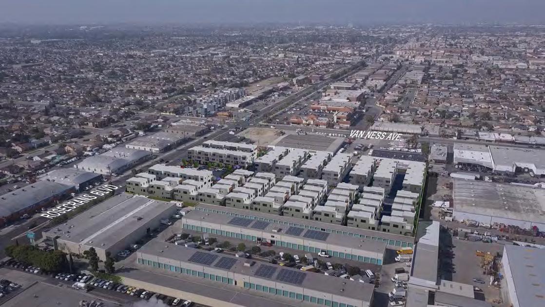
41
Vera Cruz Village
CASE STUDY NO. 3 42

43
PHOTO: GOOGLE EARTH
Vera Cruz Village Case Study No. 3
Data Summary
Project Type: Affordable Housing (Renovation)
Location: Richgrove, CA
California Climate Zone: 13
Clientele: Low-Income
Farmworkers
Gross Floor Area: 46,734 sq.ft.
Project Completed: 5/2022
Modeled EUI (Site):
19.4 kBtu/sq.ft. per yr
Measured EUI (Site):
39.7 kBtu/sq.ft. per yr. (2022)
On-Site Renewable Energy System Installed:
138 kW (DC) Solar PV
On-Site Storage Battery:
None
Measured On-Site Energy
Production:
151,133 kWh per year (2022)
Owner/Client
Self-Help Enterprises, Visalia
Design Team
Architect:
David Baker Architects, SF
Energy Consultant:
Association for Energy Affordability (AEA), Emeryville
Structural Engineer / Waterproofing:
RDH Building Science, Oakland
Mechanical, Electrical and Plumbing Engineering:
Integral Group (now Introba), Oakland
Building Envelope / Water
Heating Contractor:
Castone, Clovis
HVAC Contractor:
Munguia, MacFarland
Roofing Contractor:
Four C’s Constr., Fresno
Lighting Retrofit Contractor:
RCJ Constr., Bakersfield
Solar Contractor:
Sunrun, San Francisco
This multifamily housing project was initiated to rehabilitate existing affordable housing1 for a low-income population consisting of farmworkers in the town of Richgrove, near Delano, in Central California. It was one of several such affordable housing renovation projects undertaken by the Rocky Mountain Institute (RMI) as part of a grant to study the feasibility of retrofitting existing housing structures utilizing new building technologies while decarbonizing their energy systems and adding solar photovoltaic systems.
Background
The California Energy Commission’s (CEC) Electric Program Investment Charge (EPIC) program invests in scientific and technological research to accelerate the transformation of the electricity sector to meet the state’s energy and climate goals. REALIZE-CA is such a research grant that is funded2 to evaluate Zero-Net-Carbon (ZNC) industrialized retrofit packages that can be rapidly deployed on existing affordable multifamily buildings. This grant is managed by RMI and the Association for Energy Affordability (AEA), who are supported by a technical team including David Baker Architects (DBA), Integral Group (now Introba) and RDH Building Science. (See the list of project team firms in the Data Summary to the left.)
The REALIZE-CA research study has funded the retrofit of four affordable housing projects in California thus far to achieve lower energy consumption through energy-efficiency measures and, most importantly, all-electric energy use, making these subsidized low-income units zero carbon operationally when the electric grid is completely decarbonized in 2045. Similar projects are being added to the list of targeted all-electric retrofits with the goal of meeting California’s 2050 climate action goals.
In order to study the possible rapid deployment of certain retrofit strategies, the project scope included an innovative idea developed in Europe—the use of manufactured insulated panels that can be installed over the existing roofs and walls, including high-performance windows and doors, with minimal disruption for the occupants. While this particular approach greatly improves the energy efficiency of the retrofitted building, the conversion to all-electric energy systems is an even more significant strategy to reduce carbon emissions in the near term. This conversion requires the removal of the existing natural gas structures and related heating equipment, as well as the installation of the corresponding replacement electrical systems and appliances.
The intent of this initial project at Vera Cruz Village was therefore to establish a methodology for rapid deployment of such retrofit strategies for similar multifamily structures that would minimize the cost and the schedule duration, while permitting the occupants to remain in the units with minimal disruption. The project was essentially a “demonstration site” of standardized technical methods having some level of prefabrication, multisystem integration and more streamlined delivery in the field.
For the Vera Cruz Village project, the project team developed and executed the approach with Self-Help Enterprises (SHE), the owner and operator of the residential community since it was built in 1996. SHE was motivated by the opportunity to lower residents’ monthly utility bills, to make the living environments more comfortable and, for the larger-scale benefit, to contribute to achieving societal decarbonization goals.
1 For a summary discussion of what constitutes affordable housing, see the introductory paragraphs of Case Study No. 1, Ivy Senior Apartments, p.4 of this monograph.
2 While the CEC EPIC program provides the lead funding for the Realize-CA grant, additional funds are provided by the Low-Income Weatherization Program (LIWP), Southern California Regional Energy Network (SoCalREN), and TECH Clean California.
44 CASE STUDY NO. 3 VERA CRUZ VILLAGE Designing for Zero Carbon: Volume 2
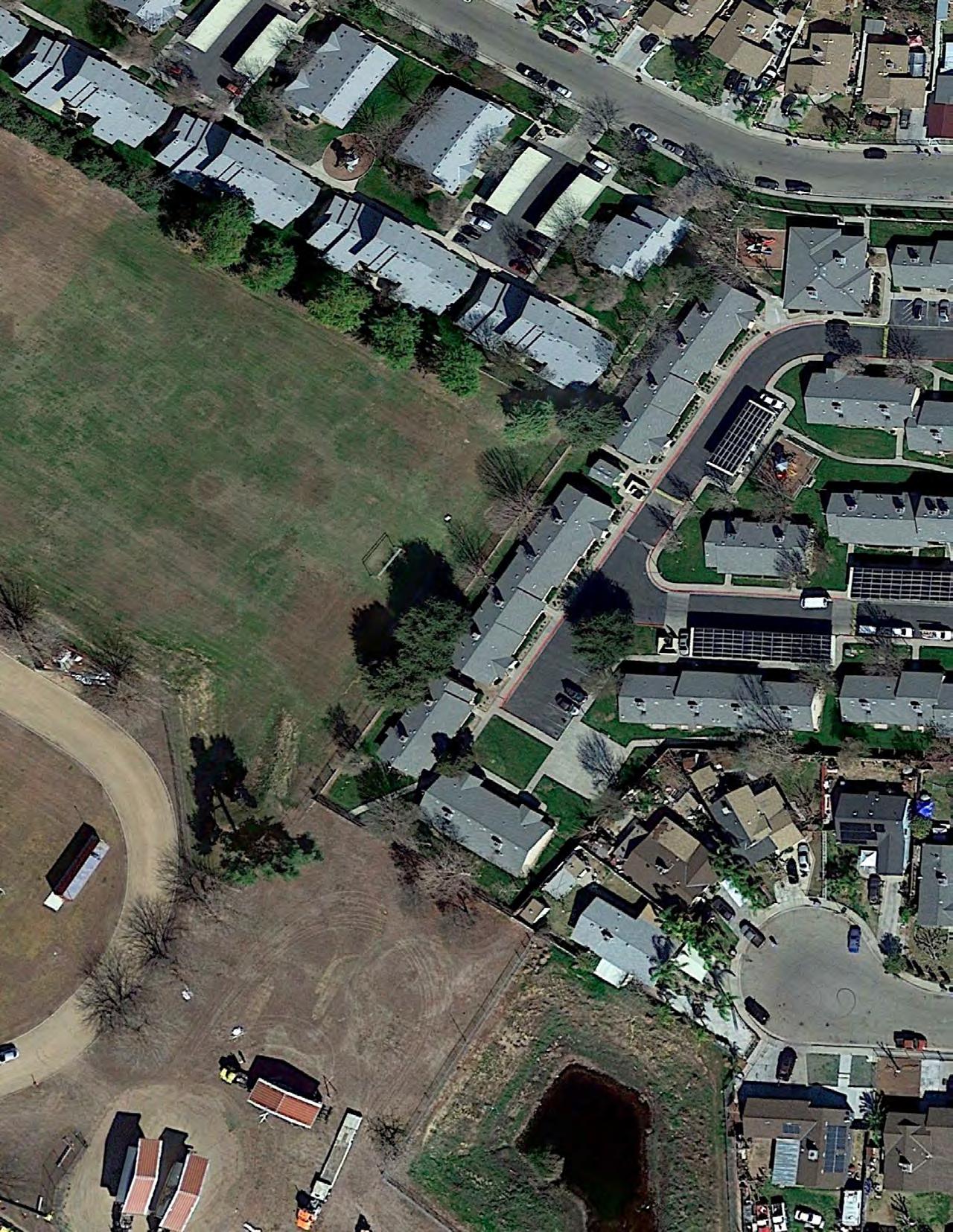
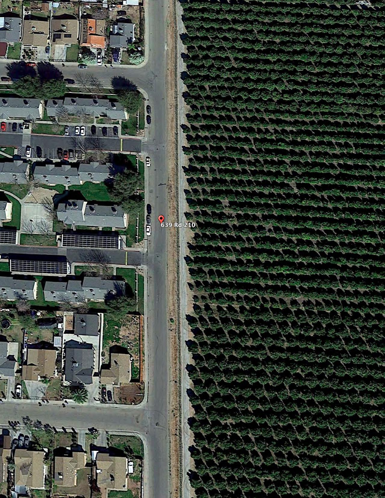
45 VERA CRUZ VILLAGE CASE STUDY NO. 3 Designing for Zero Carbon: Volume 2
Road 210 GuerreroAvenue Richgrove Drive Avenue 8
Vera Cruz Village - General Vicinity Plan
The construction work was organized and managed by SHE, which acted as general contractor in addition to working with a construction manager and an administrative consultant for prevailing-wage contracts. The several independent contractors for the total work of the project are listed in the Data Summary on the previous page.
Design Process and Low-Energy, Zero-Carbon Design Strategies
This renovation project consists of forty-nine (49) units of low-rise housing and the associated community building on the Vera Cruz Village site. The community building houses staff offices, a community room, computer lab and kitchen. The project was divided into three phases of work, each of which started construction at different times.
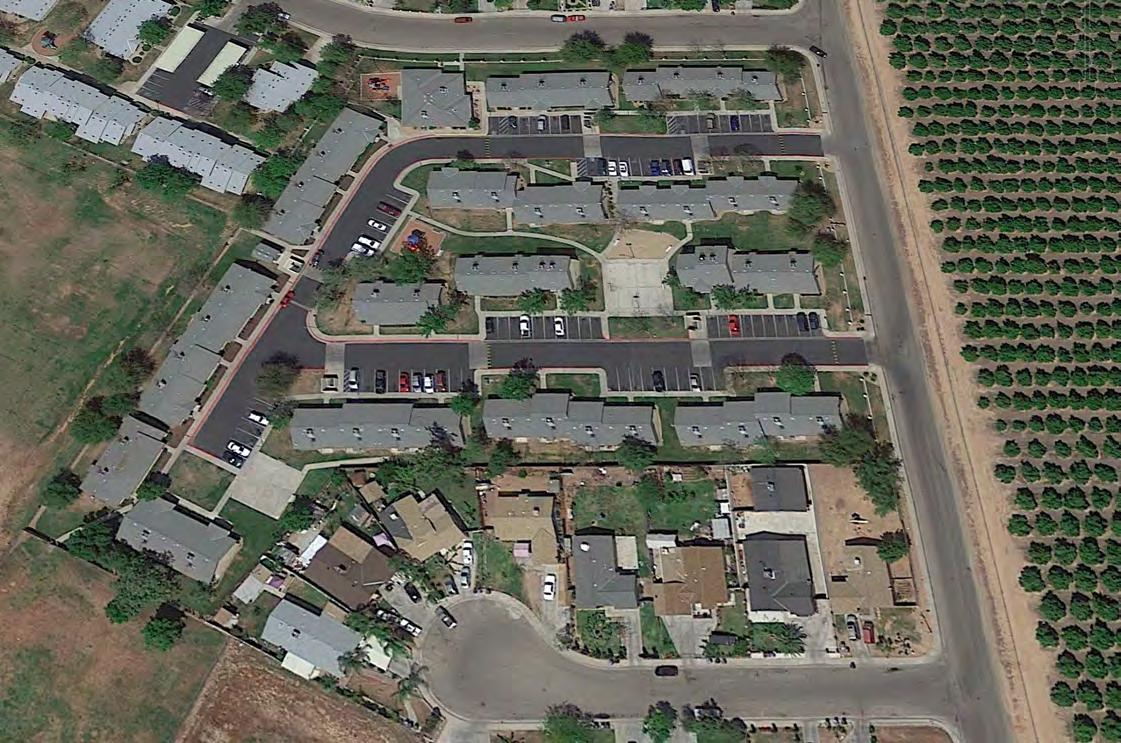
Phase 1 was the construction of canopies above the existing parking areas adjacent to the buildings and the installation of a solar PV system on those canopies. This solar PV system serves the entire complex, both the residential and community buildings, and uses a VNEM 3 to allocate the energy production benefits to the individual users of the shared system. The technical details of the first phase are described in a following section on p. 58, “Renewable On-Site Energy Supply”.
3 Virtual Net Energy Metering (VNEM) is a tariff arrangement that enables a multi-meter property owner to allocate the property’s solar PV system’s energy credits to tenants. The generated electricity does not flow directly to any tenant meter, but feeds directly back onto the grid. The participating utility then allocates the number of kilowatt-hours from the energy produced by the solar PV generating system to both the building owner’s and tenants’ individual utility accounts, based on a pre-arranged allocation agreement. The intent of VNEM is to help tenants receive the direct benefits of the building’s solar PV system, rather than all of the benefits going to the building owner. The VNEM tariffs were first piloted under the California-Solar-Initiative (CSI) Multifamily Affordable Solar Housing Program (MASH) as a means of providing equal and direct benefits of the solar PV system to low-income tenants in an affordable housing complex.
46 CASE STUDY NO. 3 VERA CRUZ VILLAGE Designing for Zero Carbon: Volume 2
Building 615
Building 619
Community Building
Road 210
Guerrero Avenue
(Left, Opposite Page) Project site in 2018, prior to the installation of the solar photovoltaic system on new canopy structures above the parking areas and all phases of the building retrofit work.
This first phase was initiated by SHE, which had installed solar PV systems at their other multifamily developments funded through the California Low-Income Weatherization Program (LIWP)4. The Vera Cruz Village installation was timed to be coordinated with the work done through the REALIZE-CA project team so that the entire retrofit project would result in an allelectric community. This work of this phase was initiated in 2019 and completed in August 2020.
Phase 2 was the main focus of the Vera Cruz Village project, namely the Demonstration Project to rehabilitate and retrofit the two central residential buildings. These two buildings, Building 615 and Building 619, contain eight apartment units. The renovation work of this phase constituted the basis of the research study, REALIZE-CA, and its primary funding by the CEC’s EPIC grant. This innovative work, intended to be standardized so that the techniques could be applied to similar affordable multifamily projects, is described in detail below.
Construction activity in Phase 2 commenced one year after Phase 1 was completed (August 2021) and was finished in March 2022. The work of Phase 3 was carried out simultaneously and was completed in May 2022.
Phase 3 consisted of the whole-building energy-efficiency retrofit of the 41 remaining apartments on the project site and the community building. The work done in this phase was a more conventional approach to energy-efficiency and electrification retrofits; a description is provided in the following sections.
Building Program
Since the project was basically to upgrade the building structures for energy efficiency and decarbonization while the residents remained in their homes, there was no change to the current building spaces and uses. Planning essentially involved the design and coordination of physical changes to the building envelope and the mechanical/electrical infrastructure, with no changes otherwise to the individual unit spaces and community rooms.
Site Constraints
The site layout provides easy access to the exterior of all buildings, with Buildings 615 and 619 located conveniently in the center of the site, with access from all sides. Similarly, there are no obstructions that would shade any panel of the canopy-mounted solar PV system.
Building Envelope – Insulation
The Demonstration Project, consisting of the energy-efficiency retrofit of Buildings 615 and 619, transformed the building envelopes. This part of the work is based on a program of retrofitting multifamily housing in the Netherlands called Energiesprong 5, which encourages whole-building solutions such as applying manufactured insulated panels to the exterior walls and roofs of buildings. The REALIZE-CA project team adapted this approach to the simple wood-frame building forms of these two buildings in the effort to demonstrate that it could be rapidly deployable for similar multifamily building types in the U.S.
4 The Low-Income Weatherization Program’s (LIWP) Multi-Family Energy Efficiency and Renewables Component of the California Department of Community Services & Development provides technical assistance and incentives for the installation of energy efficiency measures and solar photovoltaic systems in low-income multifamily dwellings serving priority populations. https:// www.csd.ca.gov/Pages/Multi-Family-Energy-Efficiency-and-Renewables.aspx 5 https://en.wikipedia.org/wiki/Energiesprong. See also: https://energiesprong. org/?country=california.
(Following Pages) The floor plans of Buildings 615 and 619 are shown on the following pages, along with an isometric drawing of each building.
47 VERA CRUZ VILLAGE CASE STUDY NO. 3 Designing for Zero Carbon: Volume 2
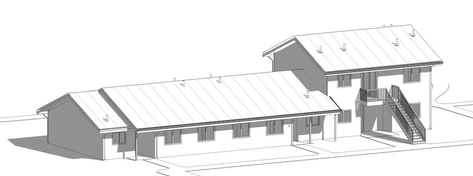
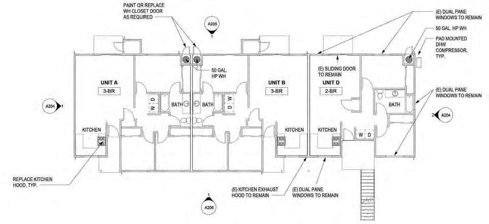
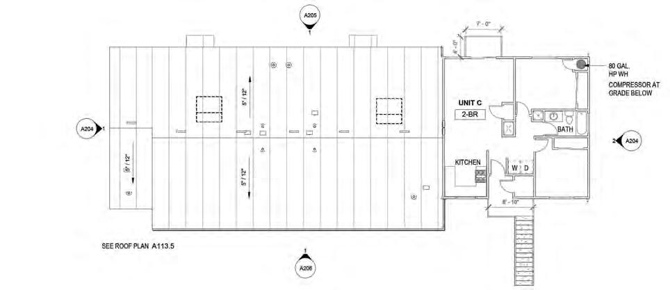
48 CASE STUDY NO. 3 VERA CRUZ VILLAGE Designing for Zero Carbon: Volume 2 VERA CRUZ VILLAGE: FLOOR PLAN BUILDING 615 NORTH FIRST FLOOR PLAN SECOND FLOOR PLAN 0 5 10 20 40 FT 0’ 2’ 4’ 8’ R
SECOND FLOOR PLAN
FIRST FLOOR PLAN
VERA CRUZ VILLAGE: FLOOR PLAN BUILDING 619
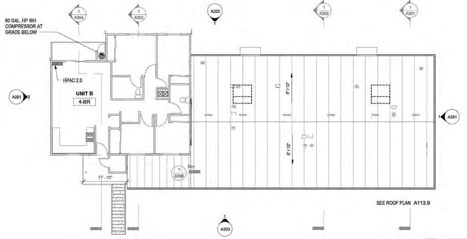
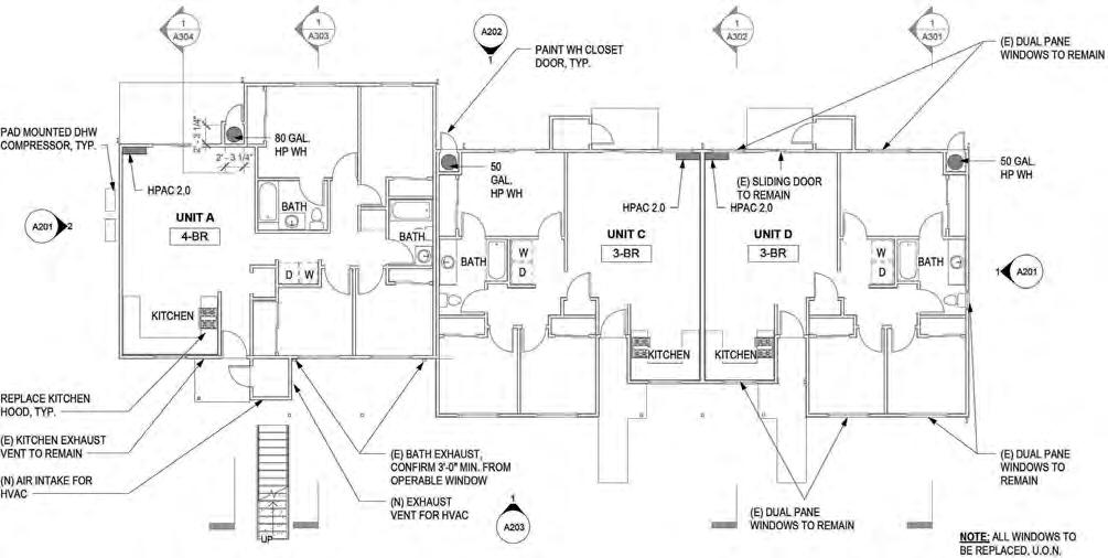
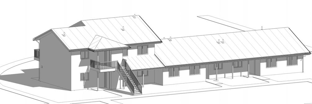
49 VERA CRUZ VILLAGE CASE STUDY NO. 3 Designing for
Volume 2
Zero Carbon:
(Opposite Page) Construction photos of the installation of the insulated metal roof panels on Building 615. Building 619 received the same roof retrofit. (Photos courtesy of John Paul Lababit, SHE.)
The project team determined early in the process that factory-made insulated wall panels would be somewhat impractical and costly for the Vera Cruz Village project. In the Dutch applications, the walls were typically simple planes with no offset surfaces or protrusions. They also generally consisted of masonry construction. There would be a greater disturbance for wood-frame structures, where occupants would be remaining in their units while the retrofit work was carried out.
The simple roof forms of these buildings, on the other hand, allowed relatively-easy application of a factory-built Insulated Metal Panel (IMP) roof system, similar to that used in the Dutch retrofit program, with manageable impact on the occupants in the spaces below. The buildings also needed roof replacements, so this aligned well with SHE’s needs for the buildings on the site.
The project team therefore opted not to use manufactured wall panels for this project, but to proceed with installation of only the high-performance IMP roof system6 on Buildings 615 and 619 as the demonstration project. The remaining buildings at Vera Cruz Village received R-38 blown cellulose in the attic spaces.
When preparing the existing roofs for the insulated metal panels, the existing roof penetrations by plumbing vents and exhaust ducts had to be modified to work with the new roof components. The details shown on the following page (page 52) were typical of such modifications required.
6 The selected product was a 4” thick IMP standing seam roof system, All-Weather Insulated Panels, Standing Seam (SR2), with R-30 foamed-in-place polyisocyanurate insulation.
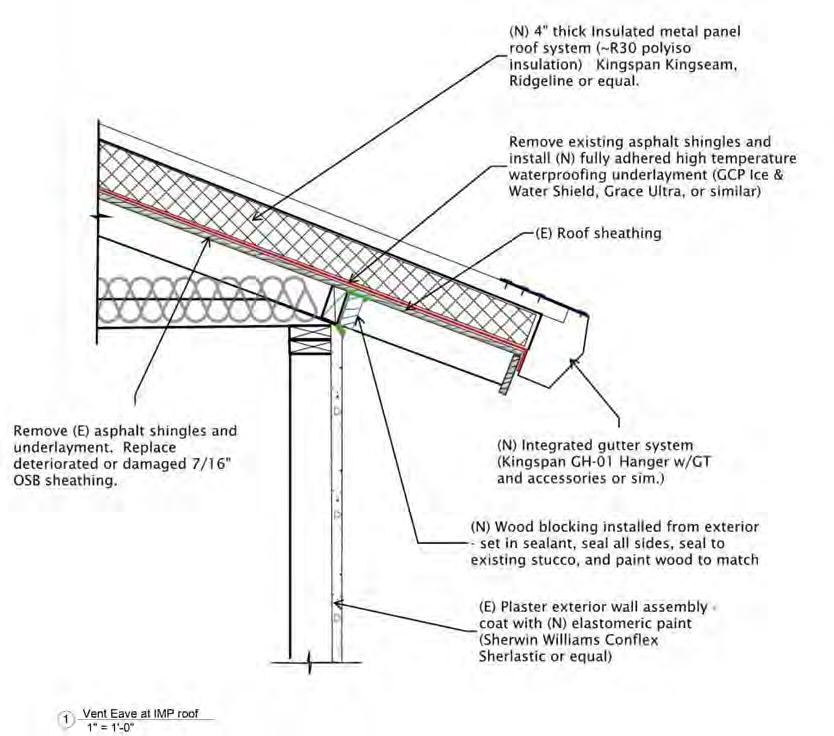
50 CASE STUDY NO. 3 VERA CRUZ VILLAGE Designing for Zero Carbon: Volume 2
(Right) Detail of roof retrofit with an insulated metal panel at the typical roof edge condition.
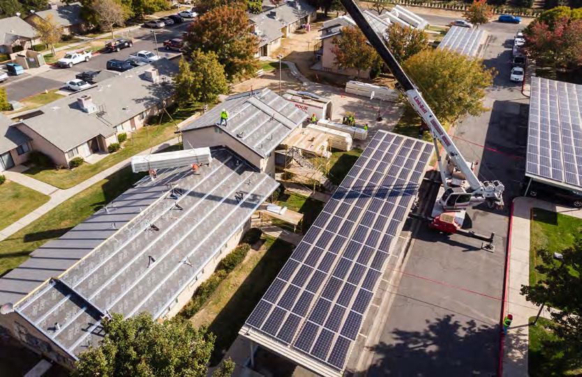
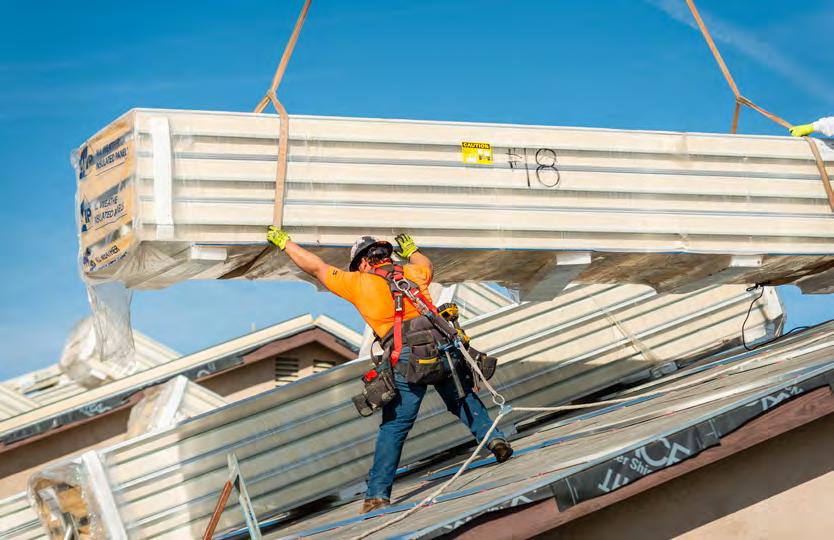
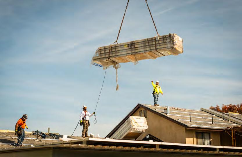
51 CASE STUDY NO. 3 Designing for Zero Carbon: Volume 2 51
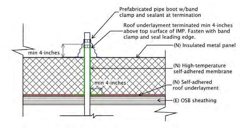
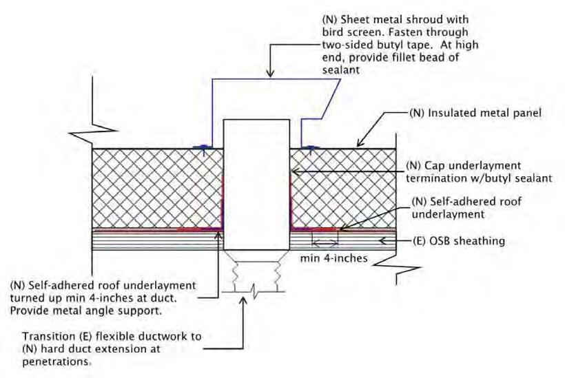
52 CASE STUDY NO. 3 VERA CRUZ VILLAGE Designing for Zero Carbon: Volume 2
Vent Pipe Penetration Flashing at IMP Roof Exhaust Vent Penetration Flashing at IMP Roof
(Right) Details of the modifications of the existing roof penetrations by plumbing vents and exhaust ducts in order to adapt to the retrofit with the insulated metal panel system.
Building Envelope – Windows
All the windows were replaced with double-glazed vinyl units7 that are compliant with the California Title-24 energy code. This was done in all the buildings, including Buildings 615 and 619. Originally, the latter buildings were specified to receive a more advanced window product, the “thin triple-pane” window 8, which has the high-performance characteristics of triple glazing at a significantly lower cost and with the physical characteristics of a double-glazed unit.
Overall cost and availability issues, however, resulted in the use of standard double-glazed units for the entire project.
Building Envelope – Airtightness
In new construction, this aspect of energy-efficient design and construction is conventionally carried out with meticulous attention to the construction details involving penetrations, openings and other sources of air transition from the exterior.9 During actual construction, this involves the manual application of airtight weather membranes, adhesive tapes and caulking. However, for existing buildings, these traditional techniques would be excessively costly or could only be applied in major renovations.
Aerosol Sealing10 is a method of air-sealing that had been originally developed for duct-sealing and used in recent years for whole-house air-sealing in new construction. It has found some application also in the air-sealing of existing wood-frame buildings. This technique can result in major improvement of the airtightness of existing structures and can be cost-effective considering the technology, time and materials involved.
With this method, the building is pressurized while dispersing an aerosol sealant “fog” to the building interior. As air escapes from the building through the leaks in the exterior envelope, sealant particles are carried to these air leakage spots where they adhere to the surfaces, effectively sealing off the leak points. The method works well for existing houses that are unoccupied and the interior surfaces and contents can be protected from the dispersing aerosol.
For occupied wood-framed buildings, this method obviously cannot be employed in this manner. If the occupied structure has an attic, however, the method can be partially utilized, sealing off the ventilated attic from the rest of the building, resulting in an improvement in the measured airtightness of the overall structure. This application involves installing the aerosol “envelope” to the attic space, air sealing the ceiling/attic surface from the attic side. All equipment and work activity during installation occurs in the attic space above the occupied space below. This was the particular approach taken using the aerosol sealing method in one building at Vera Cruz Village as part of the research study.
For a complete discussion of the aerosol sealing method, including details of how this methodology was applied at Vera Cruz Village, see Harrington et al11, referenced in the footnote below.
7 Cascade WinPro Window Series, dual-pane and low-e glass. U = 0.30, SHGC = 0.25.
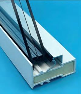
8 See https://www.energy.gov/eere/buildings/articles/bto-and-berkeley-lab-help-drive-adoptionthin-triple-paned-windows
9 Nordbye, Terry, Air-Sealing Wood-Frame Houses and Buildings, 2023.
10 See C. Harrington, F. Meyers, D. Bohac, M. Anders, L. Genty, Aerosol Sealing of Existing Residences, 2022 ACEEE Summer Study on Energy Efficiency in Buildings, https://aceee2022. conferencespot.org/event-data/pdf/catalyst_activity_32318/catalyst_activity_paper_202208101
90427374_40df278a_eddf_4668_85d8_89b87b68e957
11 Ibid.
(Above) Originally specified for Buildings 615 and 619 but removed from the project scope due to cost and availability issues, the thin triple-pane window has the same weight and structure as a double-pane window, but the low U-Value of a triple-pane window.
53 VERA CRUZ VILLAGE CASE STUDY NO. 3 Designing for Zero Carbon: Volume 2
All buildings at Vera Cruz Village received an attic sealing retrofit to improve their overall airtightness. The aerosol sealing method was used for one building as a research test case, a waterbased elastomeric sealant was used in a second building, while all the remaining buildings, including the demonstration Buildings 615 and 619, received conventional foam sealing of the attic by a specialist contractor. To further improve the air-tightness of the demonstration Buildings 615 and 619, these buildings received a coating of elastomeric paint on the stucco walls. Replacement of the windows and doors with the accompanying gasketing and sealing for the buildings completed all retrofit work that would affect the airtightness.
Blower-door tests12 were separately done on the apartment units in one representative building for each of the sealing methods, both before and after the airtightness retrofits were completed. Interestingly, all three units in the one building that received the aerosol sealing of the attic showed a 50% reduction in air leakage, from the average baseline measurement of 8.0 ACH50 (before retrofit) to 3.7 ACH50 (after retrofit).13 This is impressive compared to a typical result for the other units where the blower-door tests showed only an average reduction in air leakage of about 15%.
Heating, Ventilating and Cooling Systems
The pre-retrofit buildings were built in 1996 with rooftop HVAC package units (upgraded in 2012), which were equipped with gas-fired furnaces for heating and Direct Expanion (DX) cooling equipment. This equipment was highly visible on the roofs, providing heating and cooling to the apartments below. The all-electric retrofit of 2021-22 replaced this rooftop equipment with heat pumps, with different configurations for the apartments in the demonstration Buildings 615 and 619 and for the remaining forty-one apartments and the community buildings.
The ductwork in the demonstration Buildings 615 and 619 was replaced with more efficient duct sizes and 45° bends to minimize the pressure drop for maximum energy efficiency. For the remaining buildings, a more economical heat pump unit was installed on the roofs, which allowed relatively simple replacement of the existing gas-fired equipment. Re-use of existing ductwork in roughly half of the remaining apartment units further reduced the system installation cost, though with some loss of energy efficiency.
The heat pumps installed in the demonstration Building 619 include an integrated Energy Recovery Ventilator (ERV)14 to test the relative effectiveness of such a feature in this type of housing application. All non-demonstration units are equipped with smart thermostats.15
Domestic Hot Water Systems
All gas-fired water heaters were replaced by heat pump water heaters. The packaged heat pump water heaters were located in exterior closets with ducted make-up air. (See photo at left.)
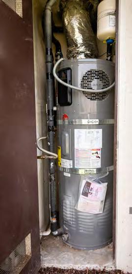
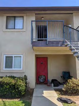
Three units in the demonstration Buildings (615C, 619A and 619B) received energy-efficient Sanden SanCO2 heat pump water heaters as a test installation, consisting of an 80-gallon tank in an exterior closet and compressor unit located outside.
12 For a discussion of this method of testing airtightness in buildings, see p.12, Zero Net Energy Case Study Homes - Volume 1, available as a free PDF at https://calbem.ibpsa.us/wp-content/ uploads/2020/04/ZNE-Case-Study-Homes-Volume-1.pdf. See also https://www.energy.gov/energysaver/blower-door-tests
13 “ACH50” = air changes per hour at 50 pascals of air pressure.
14 https://en.wikipedia.org/wiki/Energy_recovery_ventilation
15 https://en.wikipedia.org/wiki/Smart_thermostat
54 CASE STUDY NO. 3 VERA CRUZ VILLAGE Designing for Zero Carbon: Volume 2
(Above) Blower Door test in place at Building 619, Vera Cruz Village.
(Below) Packaged heat pump water heaters were located in exterior closets.
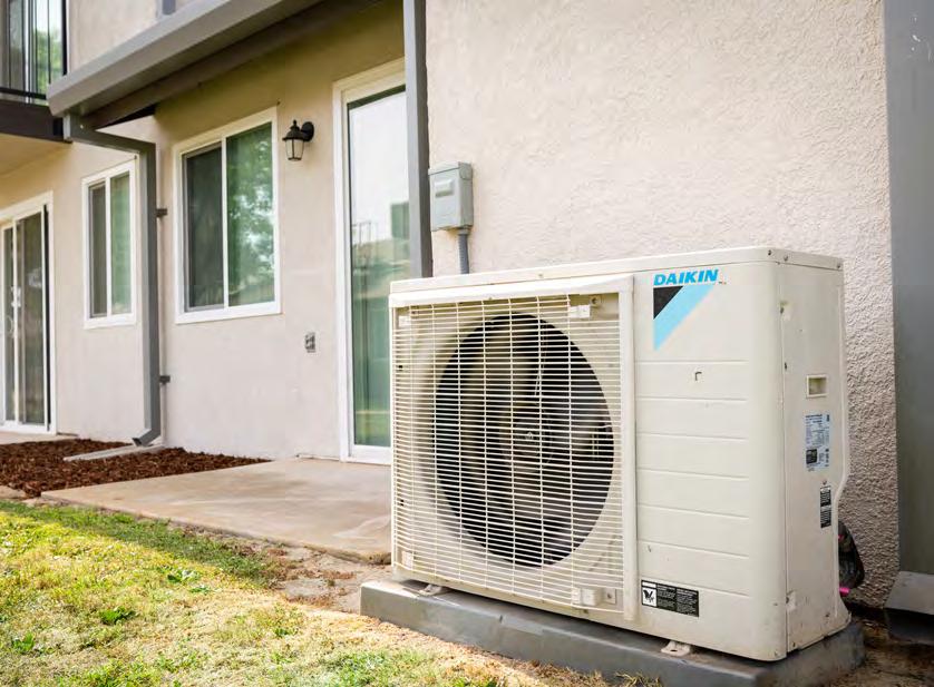
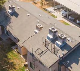
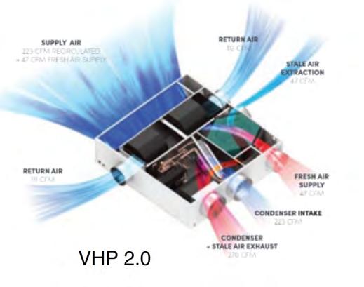
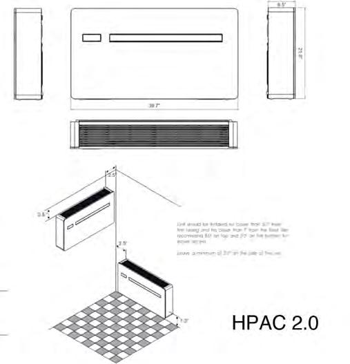
55 VERA CRUZ VILLAGE CASE STUDY NO. 3 Designing for Zero Carbon: Volume 2
(Below) View of rooftop HVAC units before retrofit.
(Left) New heat pump condenser unit after retrofit. This particular heat pump serves Apartment A of Building 615.
(Below, left) Diagram of typical ducted-air heat pump installed in attic space of Building 619.
(Below, right) Diagram of wallmounted heat pump for living rooms of large apartments.
Sealed attic insulation
Sealed attic insulation
Sealed attic insulation
Sealed attic insulation
Sealed attic insulation
PTAC heating and cooling (619)
Sealed attic insulation
LED lighting
Sealed attic insulation
LED lighting
PTAC heating and cooling (619)
PTAC heating and cooling (619)
PTAC heating and cooling (619)
PTAC heating and cooling (619)
Stucco walls with new elastomeric air barrier
Stucco walls with new elastomeric air barrier
All electric heat pump water heating
All electric heat pump water heating
Appliances
Existing electric range stoves were retained for use in the retrofitted units for cost reasons. The kitchen exhaust fans were replaced in all buildings with lower fan power hoods for higher energyefficiency. Both kitchen and bathroom exhuast fans operate continuously at low power to ensure good indoor air quality without requiring user intervention. Bathroom fans are controlled by a humidistat as well, to activate an increase in moisture removal if necessary.
Lighting and Plug Loads
All lighting in the buildings was upgraded to LED light sources.
Control Systems
Regrade away from wall base
Regrade away from wall base
Insulated metal panel roof (615 & 619)
Insulated metal panel roof (615 & 619)
An effort was made to give the users information about the new systems and how to manage the retrofitted apartments for maximum comfort and efficiency. A sample of this information is shown on the opposite page.

LED lighting
LED lighting
LED lighting
LED lighting
LED lighting
VERA CRUZ VILLAGE
New kitchen hood and continuous bath exhaust
New kitchen hood and continuous bath exhaust
Insulated metal panel roof (615 & 619)
Insulated metal panel roof (615 & 619)
Insulated metal panel roof (615 & 619)
Insulated roof (615
Insulated metal panel roof (615 & 619)
New kitchen hood and continuous
Heat pump ventilation in attic (615 & 619) or new
Heat pump ventilation in attic (615 & 619) or new roof top unit
New kitchen hood
New kitchen hood and continuous
New kitchen and continuous bath
Heat pump ventilation (615 & roof top
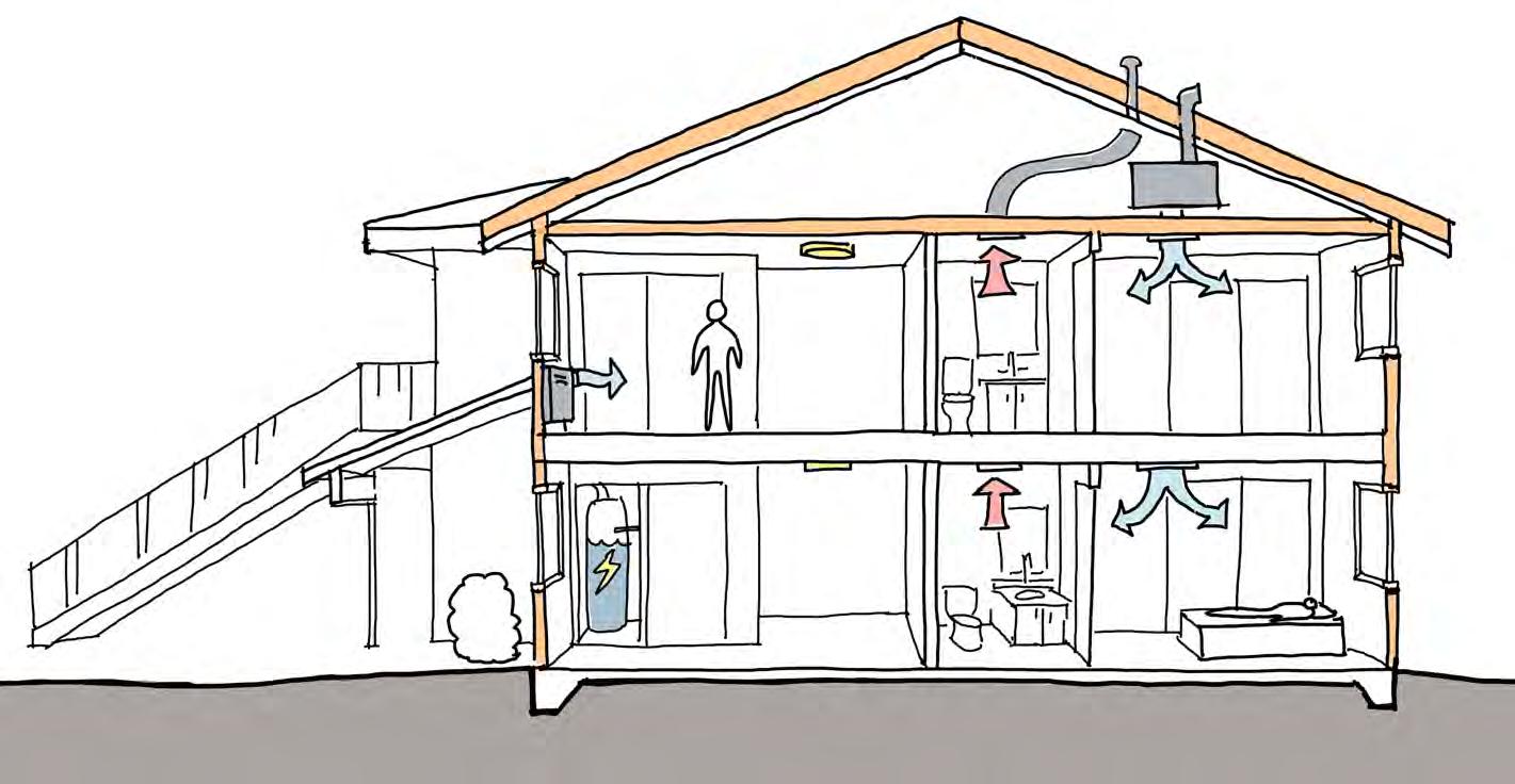
CASE STUDY NO. 3 VERA CRUZ VILLAGE
ENERGY RETROFIT VERA CRUZ
VILLAGE
CRUZ
VILLAGE
CRUZ
VILLAGE
(Below) Summary diagram of retrofit features of buildings at Vera Cruz Village.
(Opposite Page) Information flyer circulated to residents of Vera Cruz Village after the building retrofit work.
(Above) Retrofits included installation of “smart” thermostats.

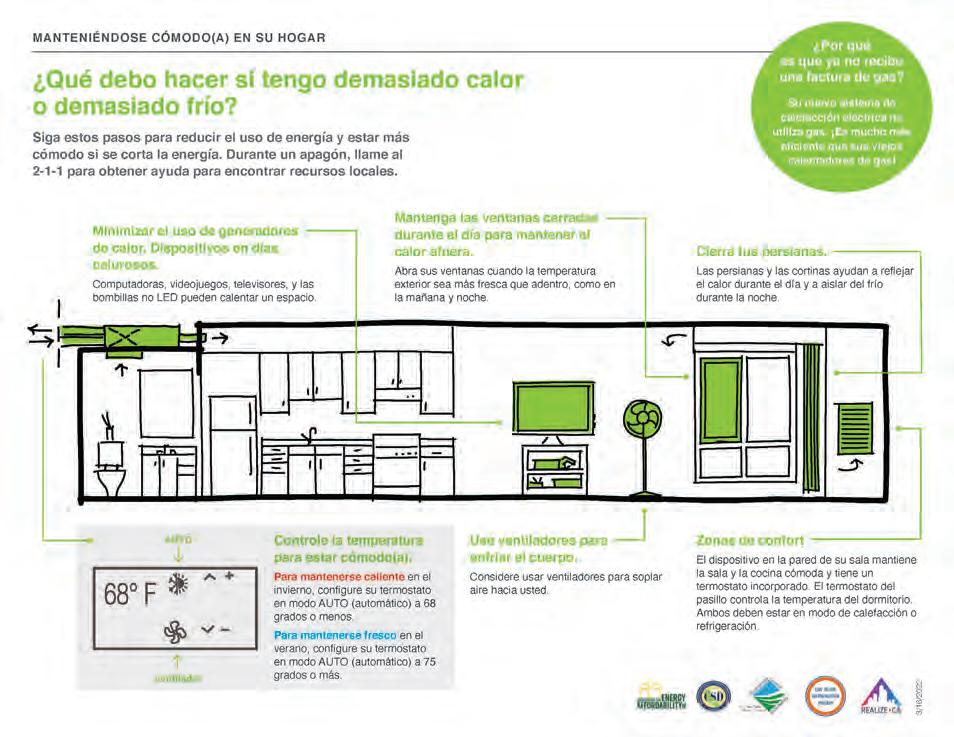
57 VERA CRUZ VILLAGE CASE STUDY NO. 3 Designing for Zero Carbon: Volume 2
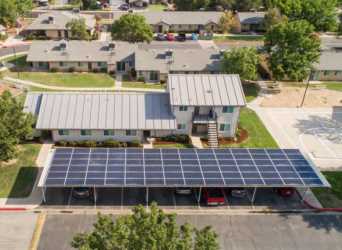
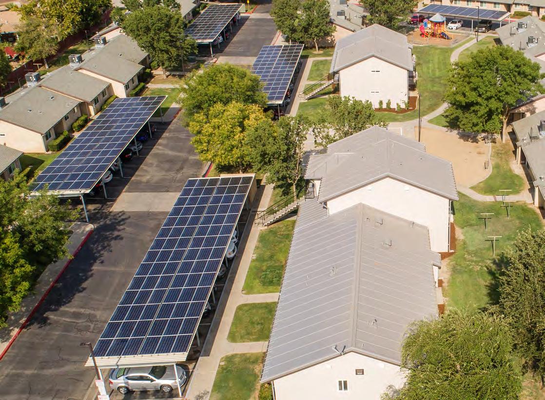
Renewable On-Site Energy Supply
Solar Photovoltaic Systems
Phase 1 of the Vera Cruz Village project consisted of the construction of five structural canopies above some of the existing parking areas and the installation on the canopy roofs of 384 solar PV panels16 totaling 138 kW. The system was installed under a third-party Power Purchase Agreement (PPA), under which the contractor, Sunrun, manages and maintains the system for a defined period of time while selling the power generated to the individual tenants (93%) and the owner (7%) according to the terms of the Virtual Net Energy Metering (VNEM) arrangement. The contractor receives the tax credits and incentives for the system’s initial cost, while the tenants benefit from a lower rate for their electricity. The construction cost of the canopies was paid for by the owner and manager of Vera Cruz Village, Self-Help Enterprises, which had secured funding through the California Low-Income Weatherization Program (LIWP).
Solar electric meters, one for each point of connection of the solar PV arrays, are mounted in a visually-prominent location for ready observation and access (see photos below). The annual productivity of the solar PV system was modeled using PVWatts17 and was measured since it was fully operational in August 2020. In 2022, the system produced 151,133 kWh, with 141,309 kWh credited to the individual apartments. These results are shown in the graph on p. 64, which also includes the aggregate total electric energy used by all the apartments. As this graph indicates, about 35% of the energy consumption was provided by the solar PV system that year.
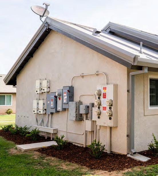
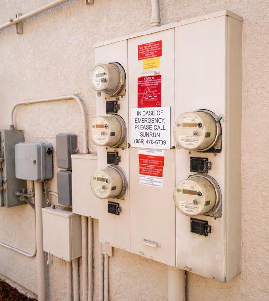
16 LONGi Solar, model type LR6-72PH-360M (360 watts-DC each). Solar Edge P400 Optimizers / Optimizers: (9) Solar Edge 11400H-US + (1) Solar Edge 3800H-US
17 https://pvwatts.nrel.gov/
59 VERA CRUZ VILLAGE CASE STUDY NO. 3 Designing for Zero Carbon: Volume 2
(Opposite Page) Installation of 384 solar PV panels on the roofs of canopies installed above five parking areas. (Photos courtesy of John Paul Lababit, SHE.)
(Below) Electric meter installation for the site solar PV system installed on five canopies.
Design Analysis: Optimizing Zero-Carbon Design
Design Analysis: Embodied Carbon

Although a detailed embodied carbon analysis was not conducted by the project team, retrofits of existing buildings typically have a much lower embodied carbon profile than building the same project as new construction, estimated between 50 to 75% less.18
Design Analysis: Energy Modeling and Operational Carbon
Energy modeling was done several times. The first energy modeling analysis was done in 2018 using Energy Pro Lite (v. 4.0) as part of Phase 1, funded by California LWIP, to evaluate the total impact of standard energy retrofit measures applied to all the apartments. A second energy modeling analysis was done in 2020 using IES VE (v.2019) software as part of Phase 2, the research study REALIZE-CA funded by the CEC EPIC program that studied the impact of the special retrofit measures to be applied only to apartment Buildings 615 and 619.
18 See E. Rosenbloom et. al., “Transforming Existing Building from Climate Liabilities to Climate Assets”, RMI Report 2023, https://rmi.org/insight/transforming-existing-buildings-from-climateliabilities-to-climate-assets/#:~:text=Low%2Dembodied%2Dcarbon%20and%20carbon,can%20 reduce%20total%20building%20emissions.&text=Investing%20in%20existing%20buildings%20 makes,constructing%20the%20same%20building%20new.
Modeled Monthly Energy Use All Apartments
Measured Monthly Energy Use All Apartments
60 CASE STUDY NO. 3 VERA CRUZ VILLAGE Designing for Zero Carbon: Volume 2
0.00 0.50 1.00 1.50 2.00 2.50 3.00 3.50 Jan FebMar Apr May JunJul Aug Sep Oct NovDec kBtu/sq.ft.
2022
265,476 kWh/year
Modeled EUI = 19.4
The Phase 1 energy modeling was separately done for the apartments and the community buildings, which would also receive similar standard energy retrofit measures (R-38 roof attic insulation, double-glazed windows and replacing all gas space heating and DHW systems with electric heat pump systems). The Phase 1 energy modeling results for the apartments only are shown in the chart below.
The Phase 2 energy modeling studied Building 619, which was retrofitted with the “demonstration” measures, and one of the 41 “other” buildings that received the conventional retrofit measures in Phase 3.
Building 619, consisting of four apartment units, was modeled with the envelope features described in the earlier sections, including the insulated metal panel system for the roofs and ordinary double-pane windows. A highly-efficient heat pump equipped with an Energy Recovery Ventilator (ERV) to capture energy from the exhaust air stream was modeled as well. The modeling results for this building in Phase 2 are shown in the charts on the next page (p. 62).
This energy modeling analysis shows that Building 619 would improve its annual energy performance from an estimated EUI of 49.9 to an improved EUI of 18.4 (kBtu/sf per year). The improvement would be greatest in the energy consumed for heating and DHW, while eliminating the entire use of natural gas for those purposes.
The “Other” building, consisting of three apartment units, was modeled with the conventional retrofit features to meet California’s Title-24 code requirements, which included double-pane windows and R-30 roof insulation. The heat pump installed for heating and cooling was a standard rooftop packaged unit (COP=3.6).
(Below) Location of the two buildings selected for the Phase 2 energy modeling of the special retrofit measures applied to the Demonstration Buildings versus the standard retrofit measures applied to the other 41 apartment buildings.
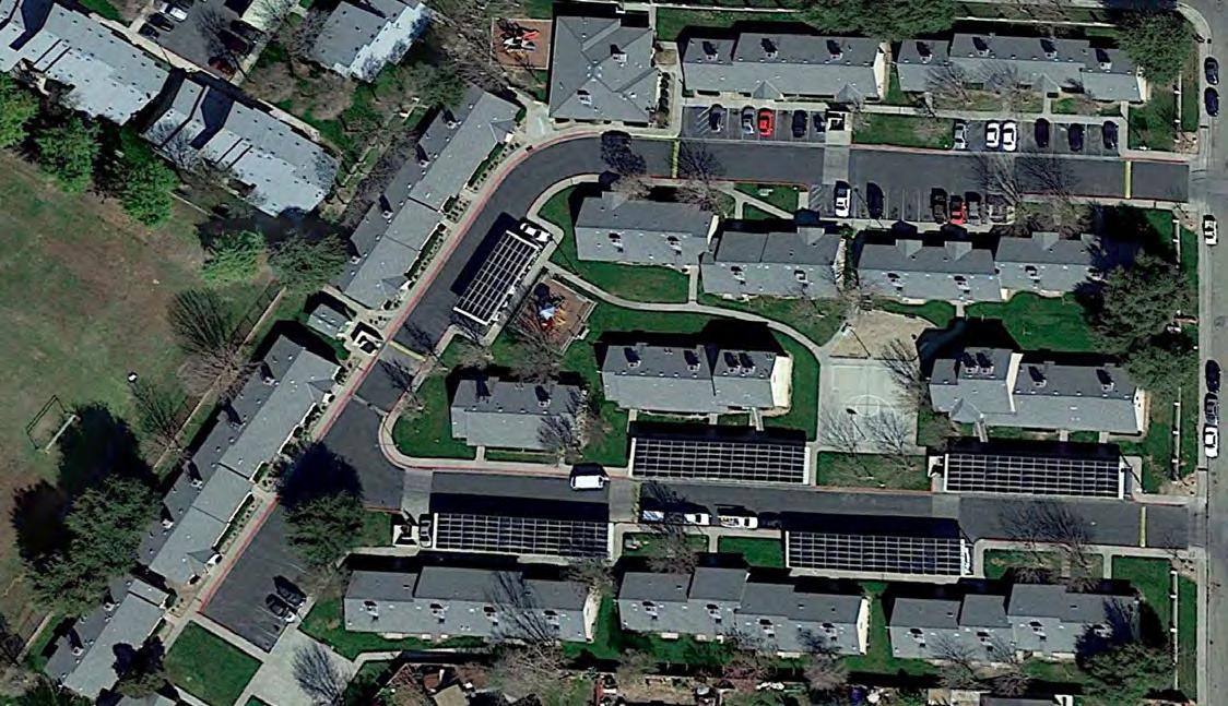
61 VERA CRUZ VILLAGE CASE STUDY NO. 3 Designing for Zero Carbon: Volume 2
“Demonstration” Building 619 “Other” Building


62 CASE STUDY NO. 3 VERA CRUZ VILLAGE Designing for Zero Carbon: Volume 2 0.00 0.50 1.00 1.50 2.00 2.50 3.00 3.50 Jan Feb Mar Apr May JunJulAug Sep OctNov Dec kBtu/sq.ft. Modeled Monthly Energy Use Building 619 -4 Units DHW Plug Load Lighting Cooling Heating Heating 28% Cooling 13% Lighting 3% Plug Load 12% DHW 44%
Annual Energy
Building 619 Modeled Annual Energy Use Building 619 - 4 Units 31,865 kWh/year Modeled EUI = 18.4
Modeled
Use
The energy modeling analysis shows that this representative “Other” building would improve its annual energy performance from an estimated EUI of 47.8 to an improved EUI of 19.6 (kBtu/sf per year) even with conventional retrofit measures. Again, the improvement would be greatest in the energy consumed for heating and DHW, even while eliminating the entire use of natural gas for these purposes.
Energy Performance and Operational Carbon: Post-Occupancy Measurement
Energy Use — Post-Occupancy Measurement
The REALIZE-CA team was able to obtain the aggregate total energy-use data from the electric utility company (Southern California Edison) for all the apartment units on the site. This data did not include the energy used by the community building or some exterior lighting, so the totals slightly understate the total project energy use. Nevertheless, the total energy use recorded for all the apartments in 2022 was 543,822 kWh, which translates to an EUI equal to 39.7. 140,554 kWh of this energy use was offset by that portion of the solar PV system dedicated to the apartments, resulting in an equivalent reduction in EUI of 10.3. Monthly totals for the aggregate energy use by all the apartments in 2022 are shown in the graph on the next page.
The actual energy use data of individual apartments was also obtained for eight units, including three units in each of the four-unit Buildings 615 and 619. The relative effectiveness of the retrofit measures used for these demonstration buildings also cannot really be estimated based on this data since the retrofit of these particular buildings was ongoing while the utility bills were being reported and recorded. Furthermore, data is not yet available for these buildings for any of the post-retrofit period (after June 2022). Therefore, the measured energy performance of these buildings is not reported in this case study.
Comparison with Energy Modeling and Operational Carbon
The Phase 1 energy modeling, which includes all apartments on the site, cannot yet be compared with the actual performance data from 2022 as represented by the chart at the top of the next page, since the retrofit construction was ongoing for a significant part of this year. The energy performance was “in transition” to lower numbers when the retrofit work was finally completed in May 2022. One year of additional energy-use data for all the apartments will provide more information about the relative effectiveness of the various retrofit measures.
The Phase 2 energy modeling was limited to two buildings, as discussed above, and the measured energy performance data could only be collected for only three apartment units in one of those buildings, Building 619. The missing data for the one apartment unit is significant for any comparison of modeled versus actual energy use for Building 619. It is a large apartment unit with exposure on three sides plus the roof surface.
Energy Production versus Energy Use
The aggregate total of energy used by all the apartment units on the project site is usefully compared to the on-site renewable energy generated by the solar PV system. This comparison is shown in the graph at the bottom of the next page (p. 64). The solar PV system provided 35% of the energy used by the apartment buildings in 2022.
Both the actual monthly amount of electric energy provided by the solar PV system and the estimated amount modeled using the PVWatts calculation method are also shown in the graph on the next page. The system underperformed in 2022 compared to that predicted by PVWatts, primarily because of the large amount of dust generated by nearby agricultural activities.
63 VERA CRUZ VILLAGE CASE STUDY NO. 3 Designing for Zero Carbon: Volume 2
Measured Monthly Energy Use All Apartments
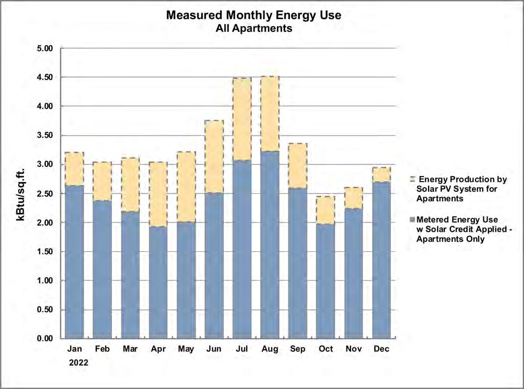
543,822 kWh/year
Measured EUI = 39.7
(Reduction in EUI due to Solar PV System = 10.3)
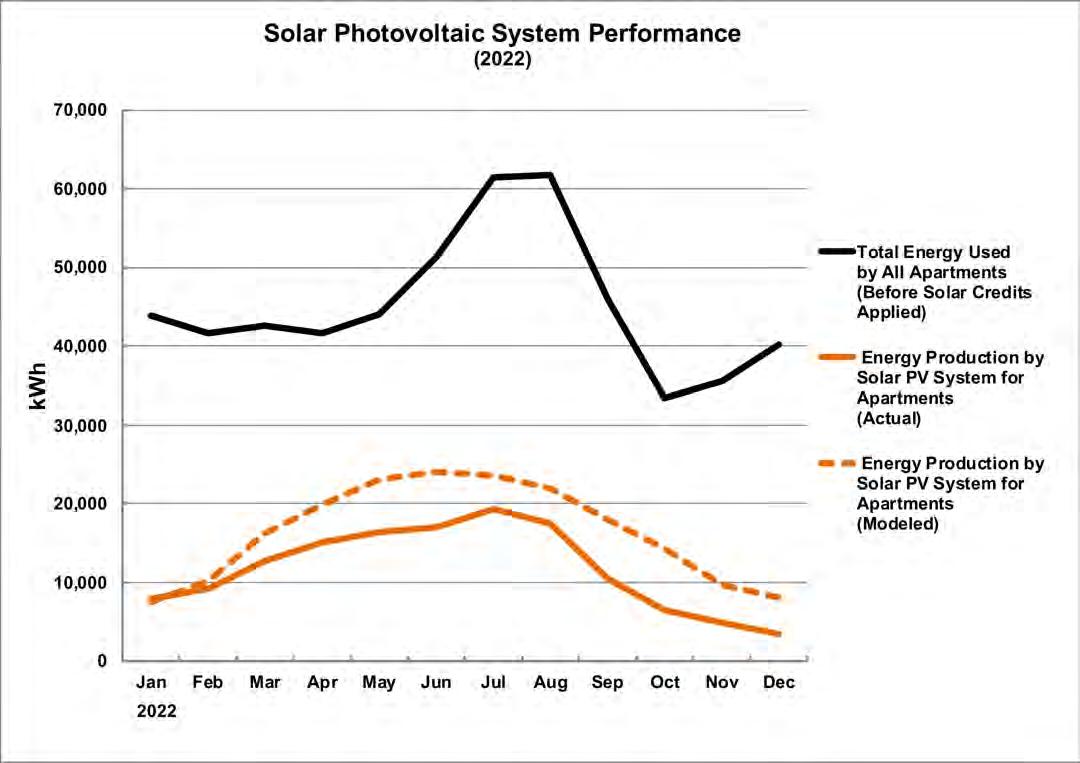
Total Metered Energy Use by ApartmentsBasis of EUI Calculation
Designing for Zero Carbon: Volume
64 CASE STUDY NO. 3 VERA CRUZ VILLAGE
2
This percentage could also be increased significantly if more canopies with solar PV arrays were installed over the remaining parking areas. However, when the utility grid is completely decarbonized as planned in 2045, the buildings will operate at zero-carbon because of this retrofit project.
Post-Occupancy: Observations and Conclusions
This retrofit project was one of four similar research and demonstration projects assessing new building technologies that had been proven in other locations but had not received wide application in Calfornia. It was to be a learning experience for the client, the professional consultants and the individual contractors that carried out the construction work. The intent was, therefore, that there would be many constructive “lessons learned” in the process.
The client shared several observations on the process:
• The project organization needed to be more direct, especially for the construction work. A conventional general contractor role, for example, would have resulted in better coordination of all the construction activities. This “GC role” fell at times to the client/owner, Self-Help Enterprises, who worked with the other project team members to oversee the project work.
• This need for a coordinating general contractor role was especially important when planning the installation of the replacememt windows and HVAC components with the tenants and with regard to weather events.
• Construction cost inflation and impacts of the pandemic were factors in this particular time period, and required an unusual amount of contingency planning.
As noted above, dust created by nearby agricultural activites at certain times of the year can affect the performance of the solar PV panels and will necessitate a special cleaning schedule.
The unexpectedly high energy use in the apartments in 2022 was caused in part by the gradual completion of the retrofitting in the early months of that year. Many of the residents used electric resistance space heaters in this winter period while work was being completed and this resulted in the higher energy use.
There were two types of project activities at this project site: the research/demonstration type in the two designated buildings and the standard building retrofit type in the remaining part of the site. The common aspect of both types of work was the electrification of the entire project site—the apartments, community buildings and shared infrastructure. The research portion of the project was successful in demonstrating that some non-mainstream technologies offer performance and/or installation process improvements, indicating that further study and application is warranted in future projects.
(Following Pages, pp 66-67)
65 VERA CRUZ VILLAGE CASE STUDY NO. 3 Designing for Zero Carbon: Volume 2
Aerial view of completed Vera Cruz Village retrofit project in August 2022. (Photo courtesy of John Paul Lababit, SHE.)
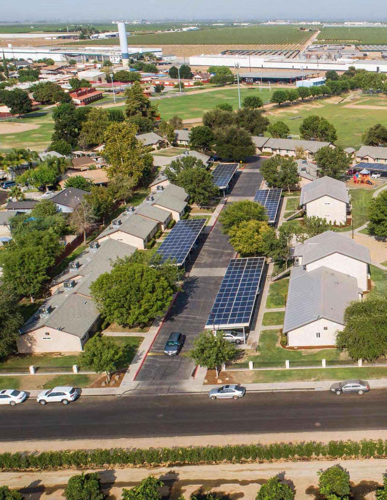
66
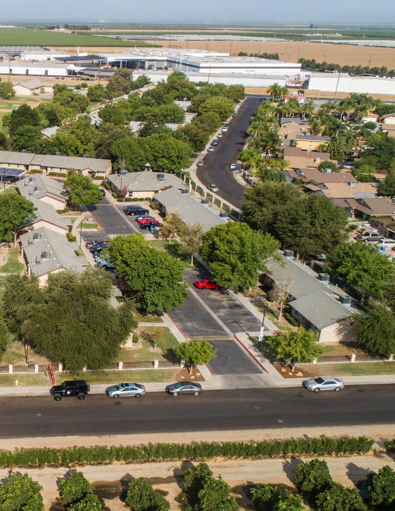
67
The Palo Alto Apartments
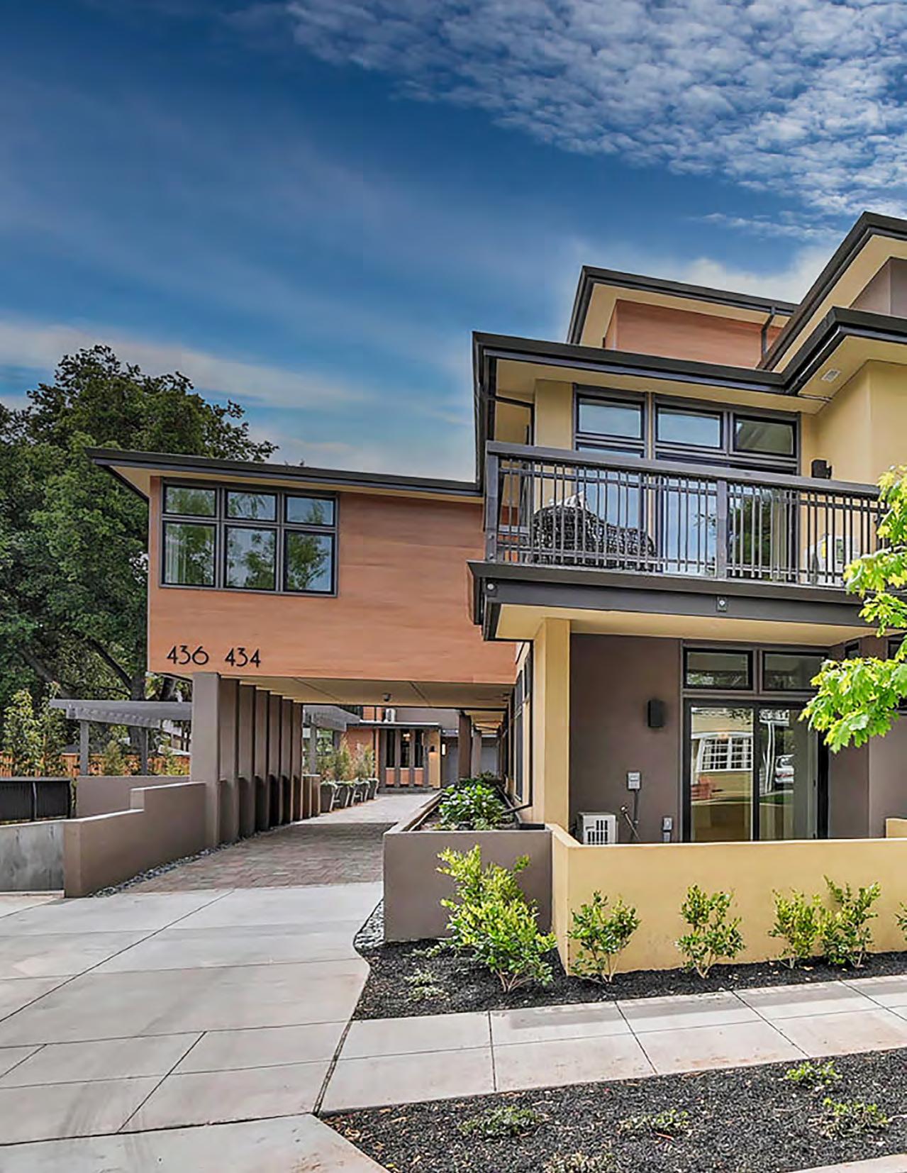
CASE STUDY NO. 4 68
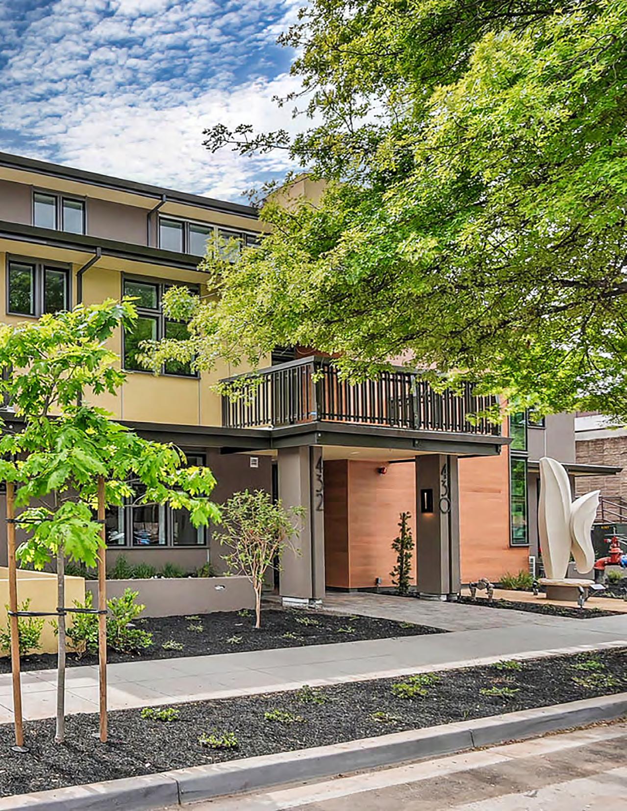
69
PHOTO: CHRIS RICKETTS, BEYOND RE MARKETING
The Palo Alto Apartments
Case Study No. 4
Data Summary
Project Type: Market-Type Units For Rent (New)
Location: Palo Alto, CA
California Climate Zone: 4
Gross Floor Area: 22,500 sq.ft.
Fully Occupied: 2018
Modeled EUI (Site):
8.3 kBtu/sq.ft. per year
Measured EUI (Site):
18.6 kBtu/sq.ft. per year (2022)
On-Site Renewable Energy System Installed:
69.8 kW (DC) Solar PV
On-Site Storage Battery: None
Measured On-Site Energy Production:
64,000 kWh per year (2020)
9.7 kBtu/sq.ft. per year (2020)
Owner/Client Sageleaf Forest LLC, Palo Alto
Design Team
Architect: David Solnick Architect, Palo Alto
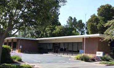
Structural Engineer: Wright Engineers, Irvine
Construction Drawings (SIP) RDH Building Science, Seattle,WA
Mechanical, Electrical and Plumbing Engineering: ACIES Engineering, Santa Clara
Energy Modeling:
EnerWhiz, Palo Alto
Landscape Architect
Linn Winterbotham, Redwood City
General Contractor: Sageleaf Forest LLC, Palo Alto
Solar Contractor: Staten Solar Corporation, Milpitas
Introduction
This case study represents another type of multifamily residential development in California housing: new construction of market-rate rental units in the general housing market. Often advertised with the descriptive term “luxury homes”, some developers seek to maximize profit through leasing rather than sales. In a market where the cost of purchasing new homes is relatively high, leasing is an attractive option, particularly if the duration of the living arrangement is seen as limited or temporary. This is the case in expensive urban areas, in communities where a college or university is located or where the job market is somewhat fluid. All of these characteristics apply to Palo Alto, California, the location of Case Study No. 4.
Background
The developer of this project, Sageleaf Forest LLC, was motivated to create a project of leasable “luxury condominium units” that were “sustainable” and technically sophisticated. This was based on a general commitment to zero-net-energy and zero-carbon goals for their buildings, but also on an understanding of the appeal of these features to the target clientele in this project location that is centered on Stanford University and the surrounding tech industry. The developer partners, electrical engineering alumni of Stanford, were naturally inclined to try out new technologies with the normally-conservative building trades, stretching the usual practices to include more innovative systems new to the building industry. This gave rise to several of the design strategies discussed below.
The developer had completed a smaller project nearby when the opportunity arose in 2015 to obtain an available site close to the main street of downtown Palo Alto, near the Stanford campus. This site was occupied by a one-story office building and a large parking lot for the Northern California club of the American Automobile Association (AAA). Located in a mixed-use zoning area of the city, it was surrounded by single-family homes, low-rise apartment buildings and single-story medical practice buildings. The developer purchased the property, assembled the design team and proceeded with the innovative design strategies for the project.
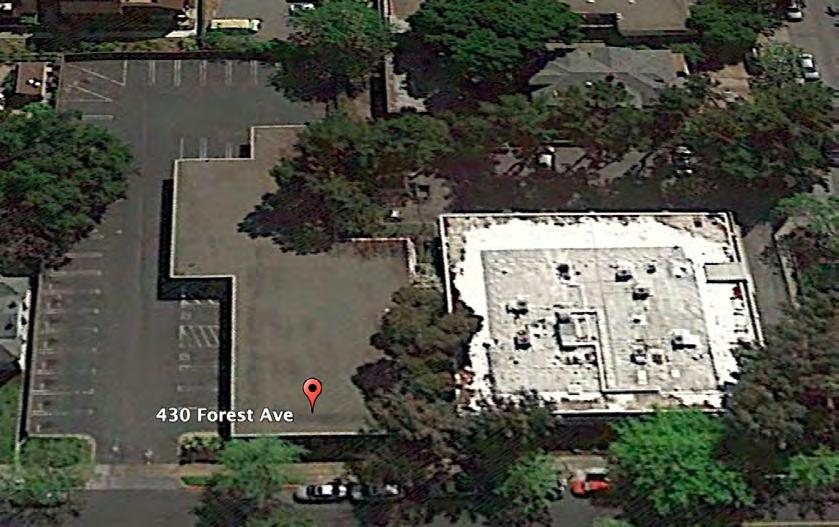
70 CASE STUDY NO. 4 THE PALO ALTO APARTMENTS Designing for Zero Carbon: Volume 2
Existing Building - 2015
71 THE PALO ALTO APARTMENTS CASE STUDY NO. 4 Designing for Zero Carbon: Volume 2
The Palo Alto Apartments - General Vicinity Plan
WaverleyStreet
HamiltonAvenue
ForestAvenue
CowperStreet
Homer Avenue
(Opposite Page) Partial view of apartment building from Common Open Space on the east side: two levels of apartments plus the penthouse level.
Design Process and Low-Energy, Zero-Carbon Design Strategies
Sageleaf Forest was both owner and general contractor for the project, utilizing the traditional expertise of architectural and engineering design professionals. Because of the approach taken for the design of the project, the company also added to the project team some firms specializing in building science (for waterproofing and airtightness), energy modeling and the high-performance building system known as Structural Insulating Panel System (SIPS). A construction management firm was also engaged to handle the day-to-day details of the construction process and to inspect the work on a regular basis and report on the progress.
The company carefully selected each firm on the project team for their specific role and was very hands-on throughout the course of design and construction. They carried out the California Title-24 energy code compliance, for example, as well as the detailed shop drawings of the SIPS system for the manufacturer. Such attention to detail helped ensure good coordination of the various atypical systems used on the project.
Building Program / Site Constraints
The architect’s initial task was to fit as many units as possible on the site within the city’s planning and zoning constraints, incorporating all the amenities and features for each apartment. The basic program called for primarily two-bedroom apartments and one special four-bedroom penthouse unit on the top floor. The city parking requirement was significant: two parking spaces per unit and guest parking spaces. Since the area required for parking would be a major portion of the site, and since the height limit was dictated in part by a daylight plane1, it was decided to place the parking in an underground level. Although an expensive solution, this would allow the maximum number of units to be built on the site.
The final program developed was ten two-bedroom apartments, the single four-bedroom penthouse apartment and two additional three-bedroom apartments at the rear of the site (denoted ”townhomes” by the developer), for a total of thirteen apartments. The required parking for this program was thirty-one (31) spaces: twenty-six (26) for the apartments, four guest parking spaces and one for the project’s small on-site office. Ample outdoor common and private deck spaces were fit into the efficient plan.
In its final configuration, the project consists of two buildings above one level of underground parking. The larger building, closest to the street, contains two levels of the two-bedroom apartments and a third level exclusively for the penthouse apartment. The second building, located at the rear of the site, consists of a pair of two-story apartments, which were able to accommodate an additional bedroom in the available space. Because the full number of required parking spaces could not be fit into the below-grade level, the parking for the rear building units was designed as conventional garages on the first level. Ramp access to the below-grade parking level and first-level driving access to the rear garages occupied the remainder of the relativelysmall downtown site.
The floor area of all apartments totals 22,500 gross square feet. The basement parking level has an area of 12,347 square feet, including an elevator and bicycle storage room. (See floor plans on the following pages.)
1 A daylight plane is an angled building height limitation that regulates the massing and design of buildings and defines the building envelope within which all new structures must be contained Daylight planes are intended to provide for light and air, and to limit the impacts of bulk and mass on adjacent properties.
72 CASE STUDY NO. 4 THE PALO ALTO APARTMENTS Designing for Zero Carbon: Volume 2
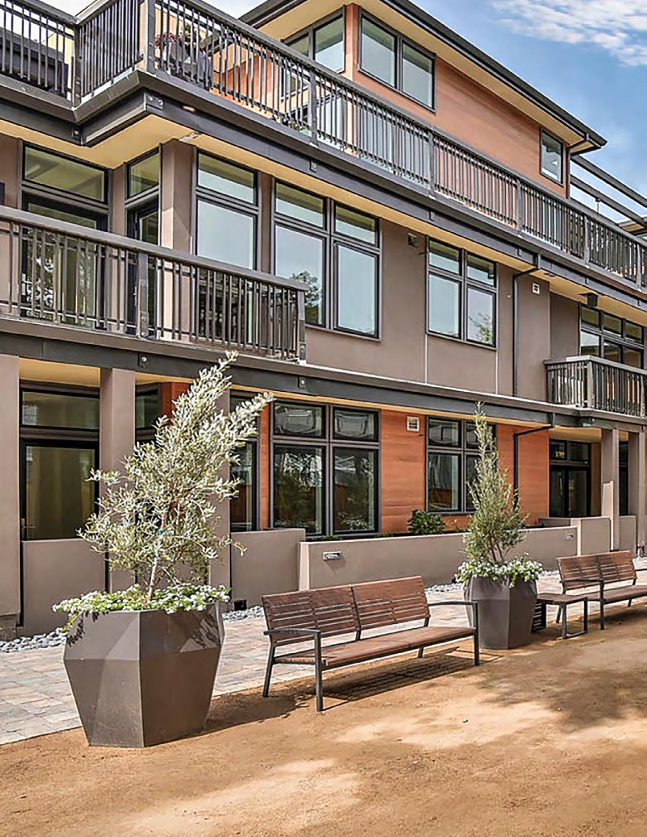
73
PHOTO: CHRIS RICKETTS, BEYOND RE MARKETING
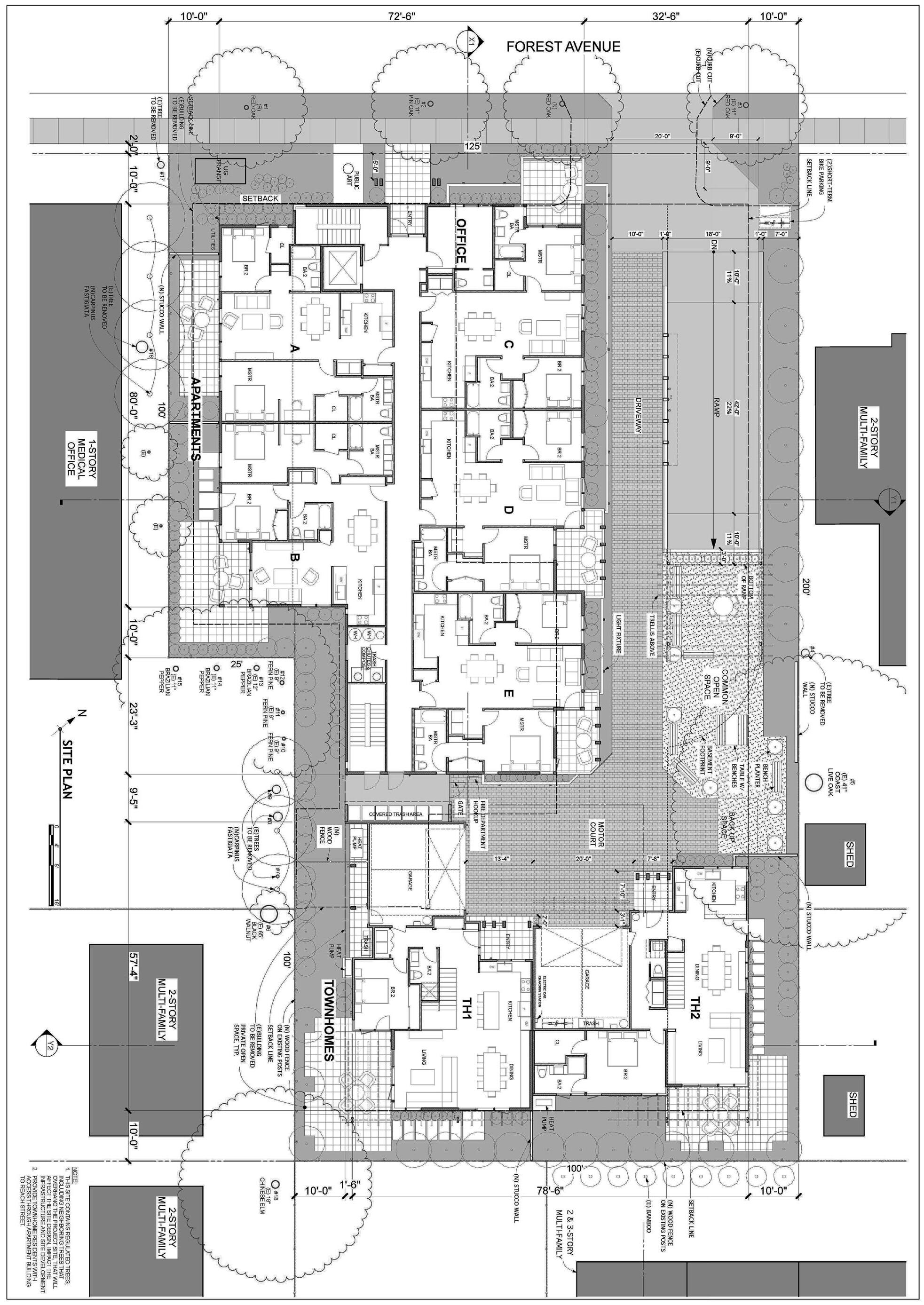


74 CASE STUDY NO. 4 THE PALO ALTO APARTMENTS Designing for Zero Carbon: Volume 2 Property Line PALO ALTO APARTMENTS: SITE PLAN AND FLOOR PLANS SITE PLAN — GROUND FLOOR PLAN 0 5 10 20 40 FT 0’ 2’ 4’ 8’ R A A
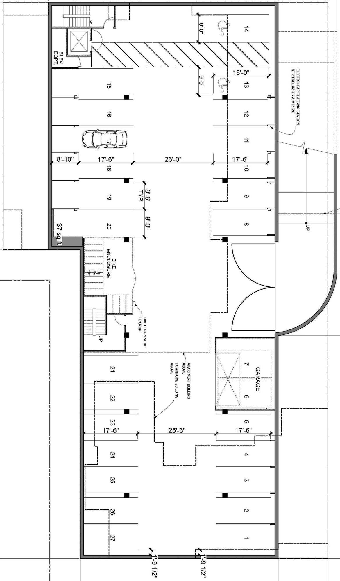
75 THE PALO ALTO APARTMENTS CASE STUDY NO. 4 Designing for Zero Carbon: Volume 2 BASEMENT GARAGE PLAN NORTH
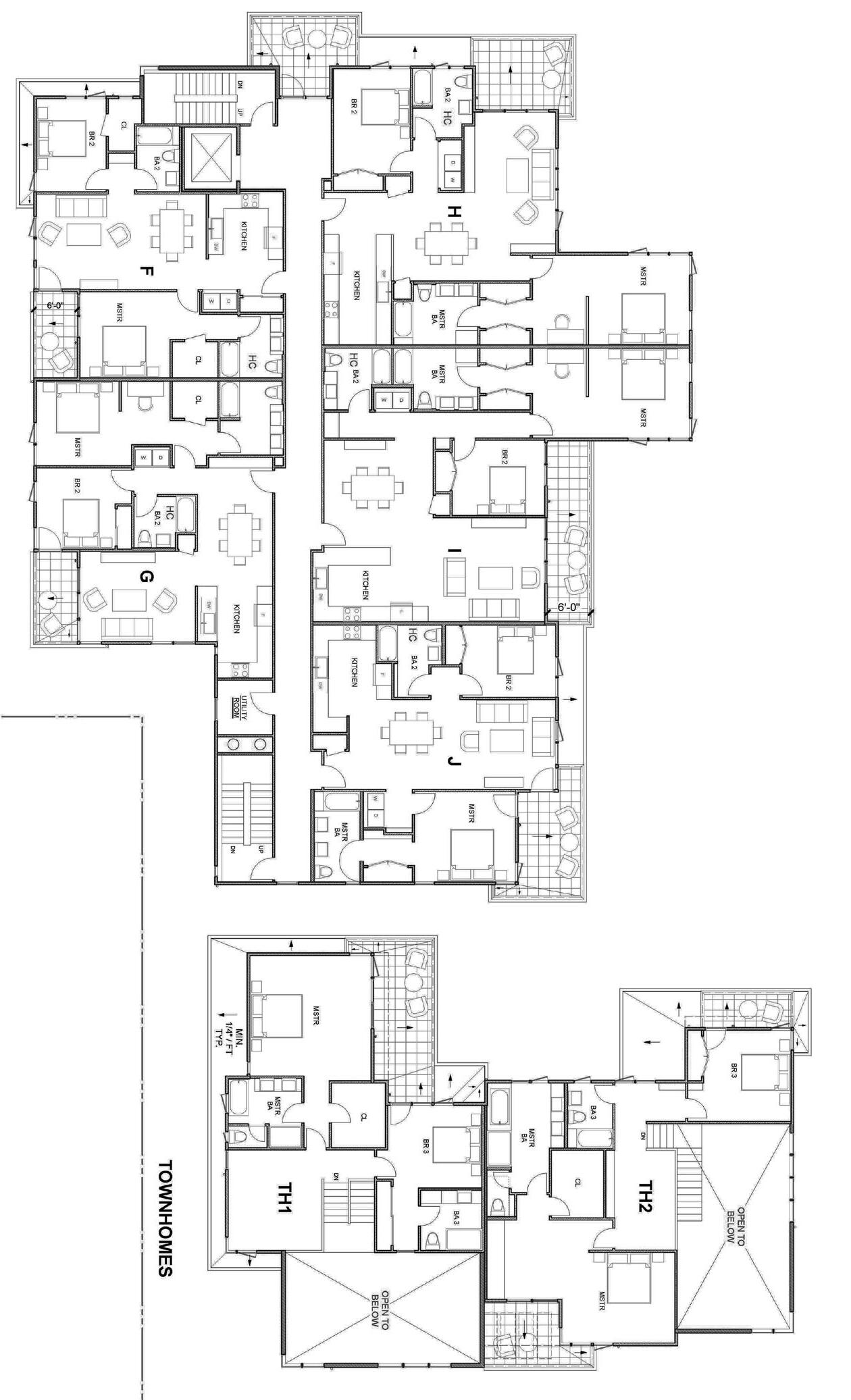
76 CASE STUDY NO. 4 THE PALO ALTO APARTMENTS Designing for Zero Carbon: Volume 2 SECOND FLOOR PLAN 0 5 10 20 40 FT 0’ 2’ 4’ 8’ R A A
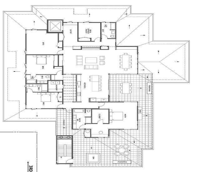
77 THE PALO ALTO APARTMENTS CASE STUDY NO. 4 Designing for Zero Carbon: Volume 2
FLOOR (PENTHOUSE) PLAN NORTH
THIRD
TRANSVERSE (CROSS) SECTION @ TOWNHOMES - LOOKING NORTH
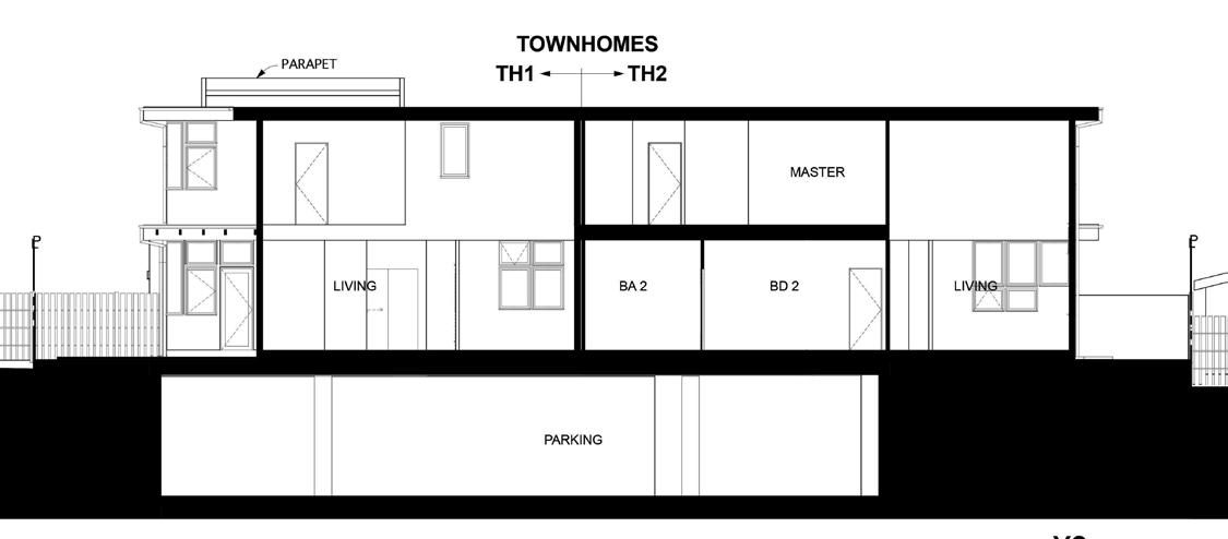
TRANSVERSE (CROSS) SECTION @ APARTMENTS - LOOKING SOUTH
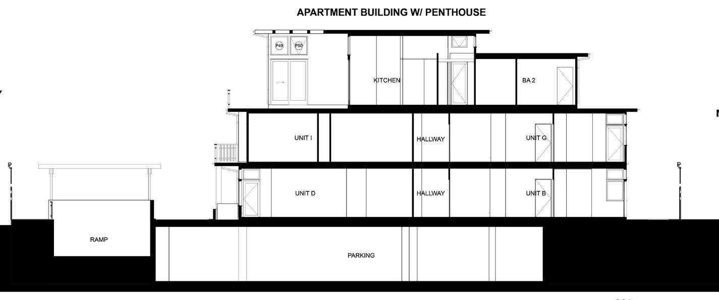
LONGITUDINAL SECTION - LOOKING EAST
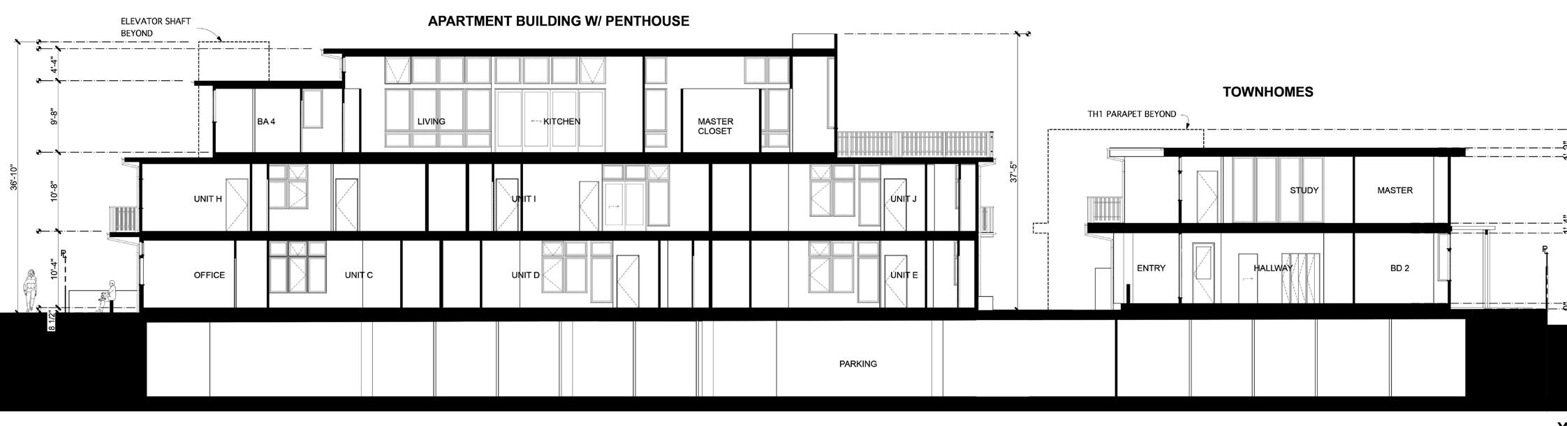
78 CASE STUDY NO. 4 THE PALO ALTO APARTMENTS Designing for Zero Carbon: Volume 2
0 5 10 20 40 FT 0’ 2’ 4’ 8’ R A A
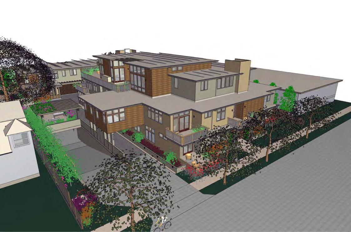
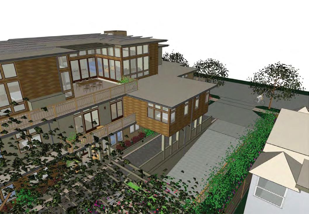
79 THE PALO ALTO APARTMENTS CASE STUDY NO. 4 Designing for Zero Carbon: Volume 2
79
Birds-Eye View from North - Forest Avenue
Birds-Eye View from East - Garage Driveway Entrance
(Opposite Page-Top)
Isometric of SIPS panel construction for the apartment building. (Courtesy of Premier SIPS)
(Opposite Page-Bottom)
Typical SIPS panel detail at outside corner (90°) where panel cladding meets the stucco finish. (Courtesy of RDH Building Science)
Building Envelope – Insulation and Windows
One of the non-traditional building systems used in this project, at least in speculative residential design in California, was the SIPS. This insulated panel system is one type of manufactured building system employed instead of conventional stick-framed structures. It uses manufactured modular panels rather than prefabricated walls to construct the building envelope of large residential structures and therefore were particularly well-suited to the design of this project.
The SIPS approach was seen by the developer as a means of obtaining high insulation values and greater structural shear resistance to earthquake forces, while potentially reducing construction time on the site. Because closed-cell foam insulation is used, there is a much higher insulation value per inch compared to conventional fiberglass insulation. Reduced construction time would also result in a lower initial project cost. This turned out to be an ideal solution for the particular size and massing of this project.
The use of the SIPS required coordination among several companies for the proper design, assembly and integration of the building envelope components. Sageleaf Forest actually produced the shop drawings for the SIPS panels, as mentioned above, which were then produced by the SIPS manufacturer.2 The weather-proofing design for the integration of the other building envelope components with the SIPS panels was developed separately by the building science consultant3. This primarily involved the details of the window and door openings, the attachment details of the exterior siding materials and the details at the deck connections.
Building Envelope – Airtightness
A SIPS structure is naturally airtight because of the large integral panels with airtight connections and the extra attention given to wall penetrations. The gaps between the large panels are sealed with a manufacturer-provided sealant. Silicone liquid-applied membrane was used as the weather-resistant barrier to seal the entire construction rather than a conventional building wrap. This type of air and moisture barrier is generally superior for increasing the airtightness of the completed structure because of its lower permeability.
The developer relied on the superior characteristics of these building components and did not perform a blower-door test to determine for each apartment unit the actual number of air changes per hour at 50 pascals of pressure (ACH50)4
2 Premier SIPS, Puyallup, WA
3 RDH Building Science, Seattle, WA
4 See the table for benchmarks of airtightness in Zero Net Energy Case Study Homes, Vol. 1, (2018), p. 12.
80 CASE STUDY NO. 4 THE PALO ALTO APARTMENTS Designing for Zero Carbon: Volume 2
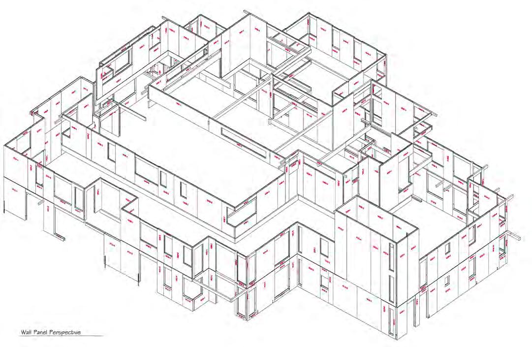
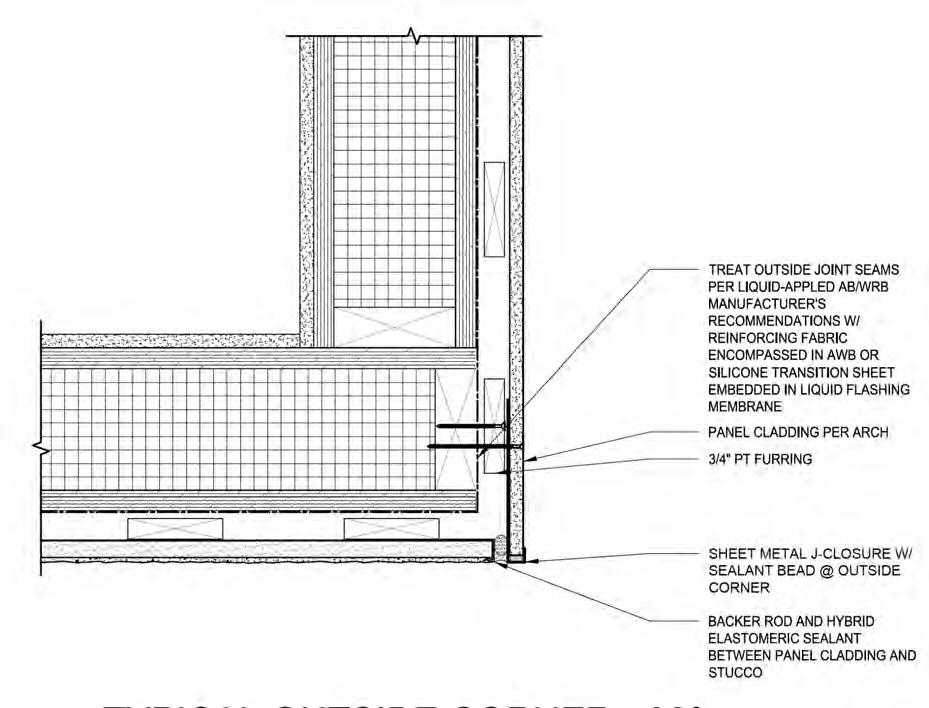
81 THE PALO ALTO APARTMENTS CASE STUDY NO. 4 Designing for Zero Carbon: Volume 2
Heating, Ventilating and Cooling Systems
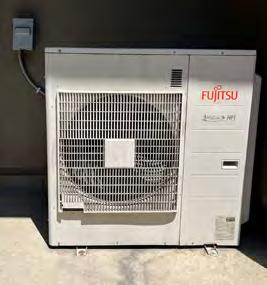
The all-electric design approach is most dramatically featured in the heating, ventilating and cooling systems of the individual apartments. Each of the thirteen apartments has its own heat pump system. Because each apartment has separate bedrooms, and therefore several zones for heating or cooling, the heat pump is essentially a “multi-split” system with separate fan units for each zone.
The penthouse unit and the larger of the two townhomes have two heat pumps to accommodate the extra number of zones in those larger units. Because the airtightness characteristics of the apartments are good but not extraordinary, the developer opted not to install an Energy Recovery Ventilator (ERV) for additional energy savings and indoor air quality5. The tenant is encouraged to open windows for fresh air ventilation in the benign Palo Alto climate.
Domestic Hot Water Systems
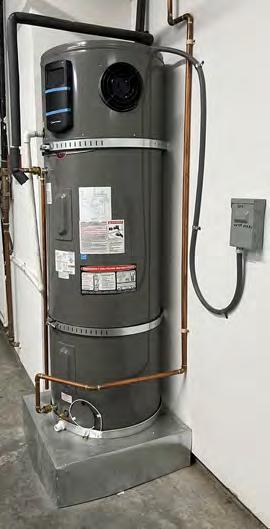
Each apartment unit has a separate heat pump water heater located in an exterior closet. This unit has the hot water storage tank built with the small heat pump unit attached at the top, requiring a tall closet to house it.
Appliances
The third heat pump in each apartment unit is a heat pump dryer. Ductless heat pump dryers avoid creating negative air pressure in the apartment, unlike standard dryers, which duct the warm moist air to the exterior, wasting energy and unavoidably sucking possibly-polluted outdoor air into the apartment. The heat pump dryer sends the warm moist air through an evaporator, which removes the moisture without losing much heat. The result is that less electric energy is used to generate the heat for the dryer appliance’s air.
The second major electric appliance in this project is the induction cooktop. While a standard electric stove could have been installed for less initial cost, the induction cooktop performs much better for the cooking process because of the amount of immediate control possible, comparable to the responsiveness of a gas or electric resistance burner. The better safety characteristics, indoor air quality and energy efficiency of the induction cooktop made it the preferred choice for the developer.
The kitchen exhaust air fan is specified to be low-powered compared with the standard high-airvolume exhaust fans since such large quantities of air flow are not needed for induction cooktops compared with gas, where indoor air pollution created by gas stove combustion byproducts requires a significantly larger volume of air removal The result: a significant reduction in energy use.
Lighting, Plug Loads and Control Systems
All lighting, which is energy-efficient LED-source, is dimmable from a smart control system app on a mobile phone6. The control system can be operated remotely and additional electric devices can be added, such as the heat pump settings, the door locks, security cameras, the wifi hub and appliances. Each of the apartments is capable of becoming a “smart home” with this system
5 For a complete discussion of the use of an ERV in an airtight house, see p. 12 in Case Study No. 6 of Zero Net Energy Case Study Homes, Vol. 2, (2020).
6 Samsung SmartThings app, https://www.samsung.com/us/smartthings/
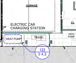
82 CASE STUDY NO. 4 THE PALO ALTO APARTMENTS Designing for Zero Carbon: Volume 2
and its electric devices.
(Above, Top) Excerpt from plan drawing of Townhome showing location of heat pump for space heating/cooling and for heat pump water heater.
(Above, Middle) Condenser of Fujitsu heat pump for space heating/cooling.
(Above, Bottom) Rheem heat pump water heater at interior location.
The common area garage lighting is low brightness when unoccupied, increasing in light level when a motion detector senses someone entering the space. All emergency lights have a battery backup system in case of a power outage.
On-Site Energy Storage: Batteries
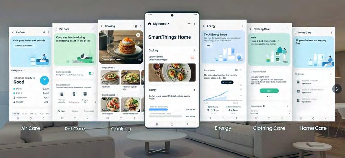
As noted, there are batteries installed only for the emergency lighting. The local electric utility company, City of Palo Alto Utilities (CPAU), did not have a time-of-use rate schedule when the project was being planned and built, nor is one planned for the immediate future. The developer therefore opted not to install a battery array for energy cost savings and resiliency.
EV Charging
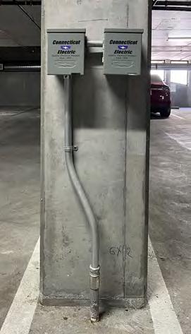
For added marketing appeal to potential tenants in this area, the developer installed four Level 2 EV charging stations7, two in the main garage and one each in the private garages serving the rear townhomes. Conduit was installed in the main garage for eleven additional Level 2 charging stations, in anticipation of future tenant requirements.
7 Level 2 charging stations are usually installed with a 220-volt outlet and are roughly four times faster charging than Level 1 charging stations. See: https://www.cityofpaloalto.org/Departments/ Utilities/Sustainability/Electric-Vehicle/EV-Chargers-for-Homes
83 THE PALO ALTO APARTMENTS CASE STUDY NO. 4 Designing for Zero Carbon: Volume 2
(Below) Electric car charging units in basement Garage.
(Above) Excerpt from Samsung SmartThings website illustrating system features.
(Following Pages) Interior of the penthouse apartment.
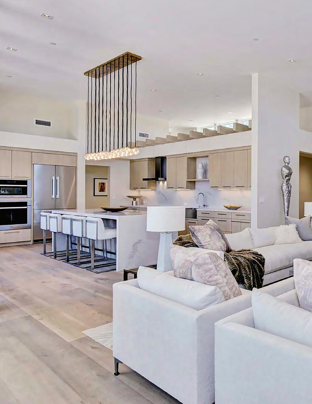
84
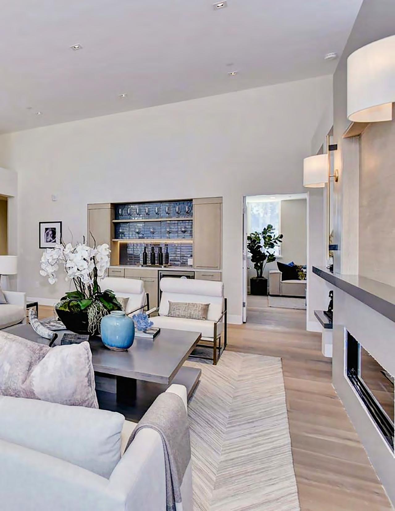
85
PHOTO: CHRIS RICKETTS, BEYOND RE MARKETING
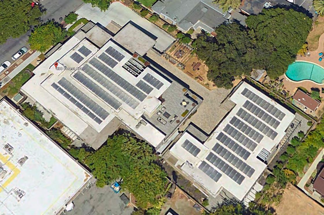

86 CASE STUDY NO. 4 THE PALO ALTO APARTMENTS Designing for Zero Carbon: Volume 2 0.00 0.25 0.50 0.75 1.00 1.25 1.50 1.75 2.00 2.25 2.50 Jan Feb Mar Apr May JunJulAug Sep OctNov Dec kBtu/sq.ft.
Monthly Energy Use
Modeled
55,000 kWh/year
Modeled EUI = 8.3
Monthly Energy Use (EnergyPro v5.1 Software)
Modeled
Renewable On-Site Energy Supply
Solar Photovoltaic Systems
The solar photovoltaic system basically covers the rooftops of the two buildings (see the Google Earth image on opposite page) providing almost 70% of the electric power required by the thirteen apartment units, including the EV charging loads. The panels are high-performance bifacial panels that take advantage of the light-colored roof membrane to collect solar energy from both sides of the panel. 178 Sunpreme GxB-370W panels comprise the 65.86 kW system. The DC power from these panels is efficiently converted to AC power by the system inverters, Fronius Symo, 15.0 kW and 12.0 kW.
Toward the end of 2021, a problem developed with the functioning of the inverters that led to a significant drop-off in the production of the solar PV system. Because of the ongoing pandemic and reporting errors, this situation has only recently been confirmed, and corrective measures have been initiated. The most recent year of recorded full production was 2020; 2023 is expected to be a return to that expected optimal production.
Design Analysis: Optimizing Zero-Carbon Design
Design Analysis: Embodied Carbon
An embodied carbon analysis was not done. Tight site constraints and city planning requirements set the design as realized, requiring the concrete walls of the below-grade parking level, a high embodied carbon component.
Design Analysis: Energy Modeling and Operational Carbon
Energy-use modeling was undertaken as part of the Title-24 compliance documentation, using the California-mandated Energy Pro software (Version 5.1). The total annual energy use for each of the two buildings was calculated and Title-24 compliance was confirmed. The energy-use model predicted an annual energy consumption for the buildings, exclusive of any EV-charging energy use, of 55,000 kWh. For the 22,500 sq. ft. of conditioned building space, this translates to a predicted EUI of 8.3 kBtu/sq.ft. per year. (See the graph on the previous page.)
The annual energy production of the solar PV system was modeled using the PVsyst8 software. Analysis showed that 178 bifacial Sunpreme panels would deliver an estimated annual production total of 100,000 kWh, almost double the predicted annual energy consumption of the two buildings, and large enough to cover the loads created by the future fifteen EV chargers. In other words, the solar PV system as designed was expected to produce a project that was at least ZNE when fully operational.
The results of the PVsyst modeling analysis is shown in the graph on p. 89, along with the plot of the actual measured performance of the solar photovoltaic system in 2020, the last data recorded when the solar PV system was operating properly in the latter half of that year. As can be seen, the actual performance closely tracked that predicted by the model for those six months.
(Oppsoite Page, Top) Birdseye view of the roofs of the two apartment buildings, showing the installation layout of the 178 solar PV panels. (Image from Google Earth)
8 PVsyst is advertised as a “preliminary design tool” for the estimating solar PV system energy production. https://www.pvsyst.com/
87 THE PALO ALTO APARTMENTS CASE STUDY NO. 4 Designing for Zero Carbon: Volume 2
Energy Performance and Operational Carbon: Post-Occupancy Measurement
Energy Use — Post-Occupancy Measurement
Palo Alto Utilities, the department that operates utility services for the City of Palo Alto, provided energy use data for a 12-month period beginning in February of 2022. The energy provided by the public utility as recorded in the bills, plus the energy provided by the on-site solar PV system, was the energy used by the project buildings and common garage, including the four EV charging units that were installed and operational.
The project energy use in 2022, notably including EV charging, totaled 123,000 kWh, more than double that predicted by the energy modeling software for the two buildings alone. The actual EUI for the project in that 12-month period was 18.6 kBtu/sq.ft. per year. See the graph on the opposite page (top).
While the large difference is attributable, in some degree, to the use of the four EV charging units, it is also likely due to the fact that the tenants are not paying for the electricity used. Energy use is currently included in the rental charges. The developer, which is still managing and maintaining the property, plans to install submeters for each apartment and for the common areas in order to remedy this situation. In the future, the energy use totals for the buildings alone will be accurately totaled and can be compared to the predicted EUI in a more meaningful way. The reporting of the individual energy use to each tenant is expected to reduce the energy consumption significantly.
Energy Production versus Energy Use
For the same period of time, the solar PV system was experiencing the problems noted above with the inverter operation, which led to a sizable reduction in the output and the contribution by the solar PV system. The net result was a shortfall of about 35% from the predicted amount, causing the project to fall well short of the predicted ZNE performance. With the correction of the inverter problem, it is expected that the energy produced by the solar PV system will align with the building energy use, particularly if the energy use for EV charging, expected to be substantial in the next few years, is accounted for separately.
The graph on the opposite page (bottom) demonstrates this expectation to some extent. In this chart, the actual energy use of the project for 2022, including just four EV chargers, is plotted with the most productive year of data for the solar PV system (2019) prior to the inverter failures. In addition, a plot of the modeled energy production (the ideal expected amount) of the solar PV system is superimposed on these two data plots. As can be seen, there is a likely balance of energy production with energy use that could result in achieving the original goal of ZNE performance for the buildings.
88 CASE STUDY NO. 4 THE PALO ALTO APARTMENTS Designing for Zero Carbon: Volume 2
Measured Monthly
Measured Monthly Energy Use (2022-2023)
Use (2022 - 2023)
123,000 kWh/year Measured EUI = 18.6
Solar Photovoltaic System Performance
Solar Photovoltaic System Performance
Energy ProductionPVSyst Model


Energy UseBuildings+EV Charging (Year: 2022-2023)
Energy ProductionActual (Year: 2019-2020)
89 THE PALO ALTO APARTMENTS CASE STUDY NO. 4 Designing for Zero Carbon: Volume 2 0.00 0.25 0.50 0.75 1.00 1.25 1.50 1.75 2.00 2.25 2.50 Feb Mar Apr May JunJulAug Sep OctNov DecJan kBtu/sq.ft.
2022 2023 0 2,000 4,000 6,000 8,000 10,000 12,000 14,000 FebMar Apr May JunJul Aug Sep Oct NovDec Jan kWh
Energy
Post-Occupancy: Observations and Conclusions
As observed with previous residential projects in these case study books, there should be a specific “commissioning” phase similar to non-residential projects, where the various systems are monitored for a specified period after occupancy to ensure their optimal performance. This has proven to be particularly true for the solar PV systems, where performance is sometimes lower than design expectations. This under-performance may be due to component failure, as in the case of the inverters for this project, or simple maintenance issues. Most of these problems can be avoided by instituting a commissioning phase at the end of construction and collecting data to verify consistently-good performance for a period of time.
Another “lesson learned” for any multifamily residential project serving the rental market is that it is always beneficial for minimizing energy use to have tenants be responsible for their own energy bills. This encourages efficient use of energy and avoids wastefulness. Submetering and data collection, with reporting to individual tenants, is also useful in developing a group consciousness of the energy use and carbon footprint of the project as a whole.
Embodied carbon analysis normally should be done to reveal any alternative material or product choices that may be noteworthy for lower carbon emissions to produce. This project was designed in 2018, just as analytical tools for embodied carbon analysis were becoming more available. Given that material choices were highly restrained because of site and planning constraints, it seems unlikely that the project would have been designed differently. An embodied carbon analysis would likely have confirmed this.
90 CASE STUDY NO. 4 THE PALO ALTO APARTMENTS Designing for Zero Carbon: Volume 2
(Oppsoite Page) Interiors of Townhome Unit 2.
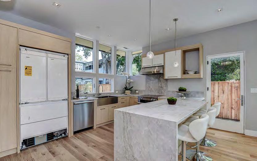
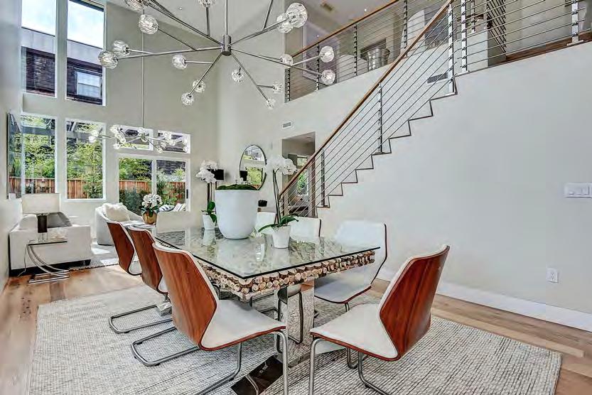
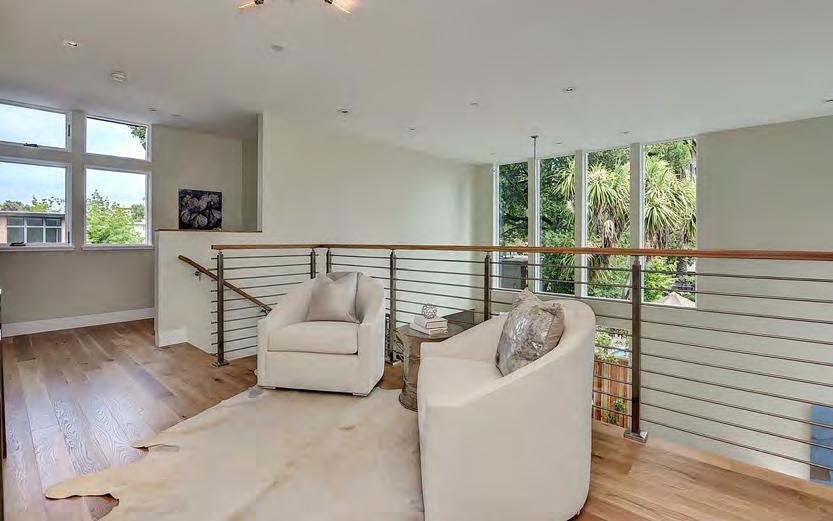
91 THE PALO ALTO APARTMENTS CASE STUDY NO. 4 Designing for Zero Carbon: Volume 2
91
PHOTOS: CHRIS RICKETTS BEYOND RE MARKETING
Casa Adelante at 2060 Folsom
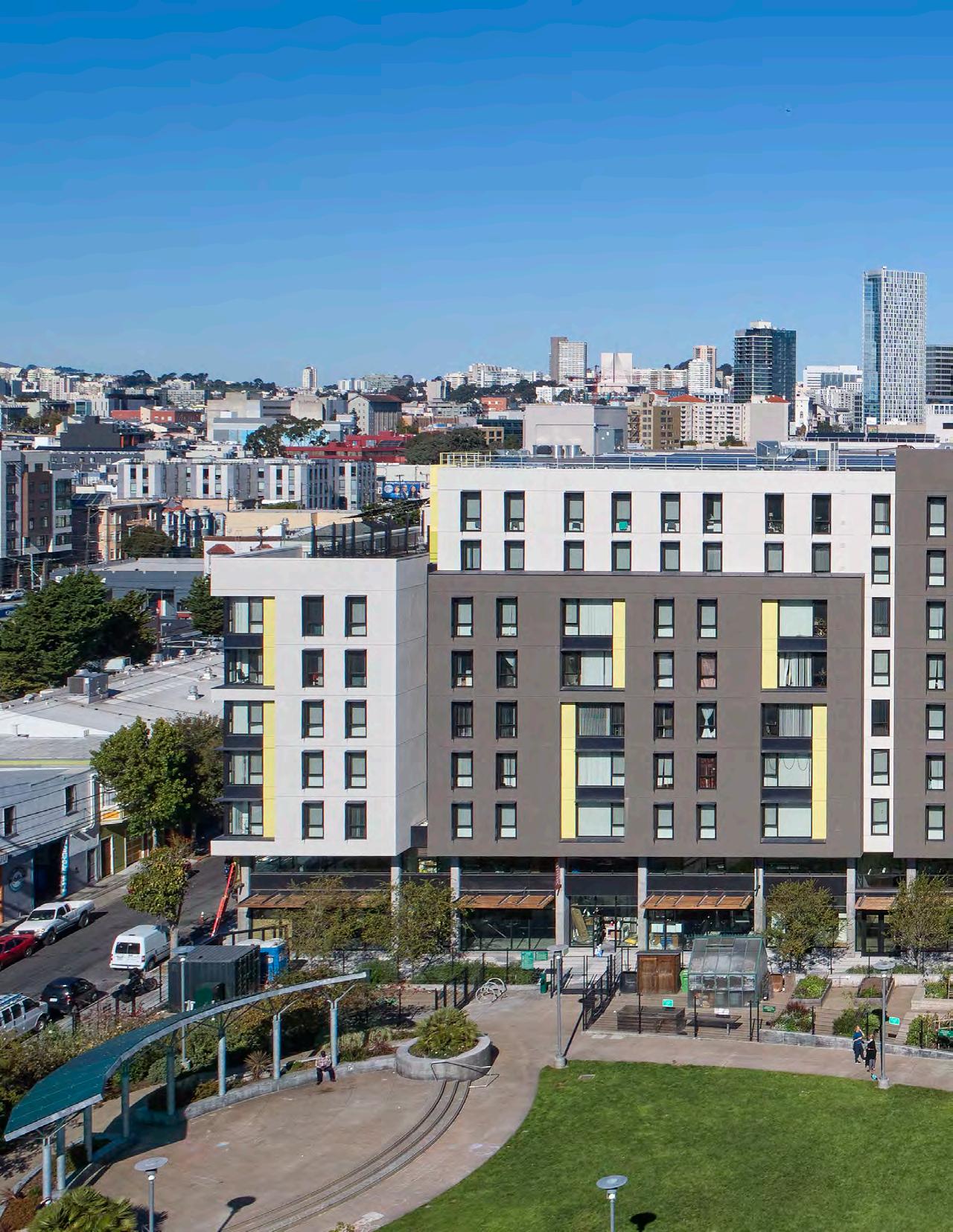
CASE STUDY NO. 5 92
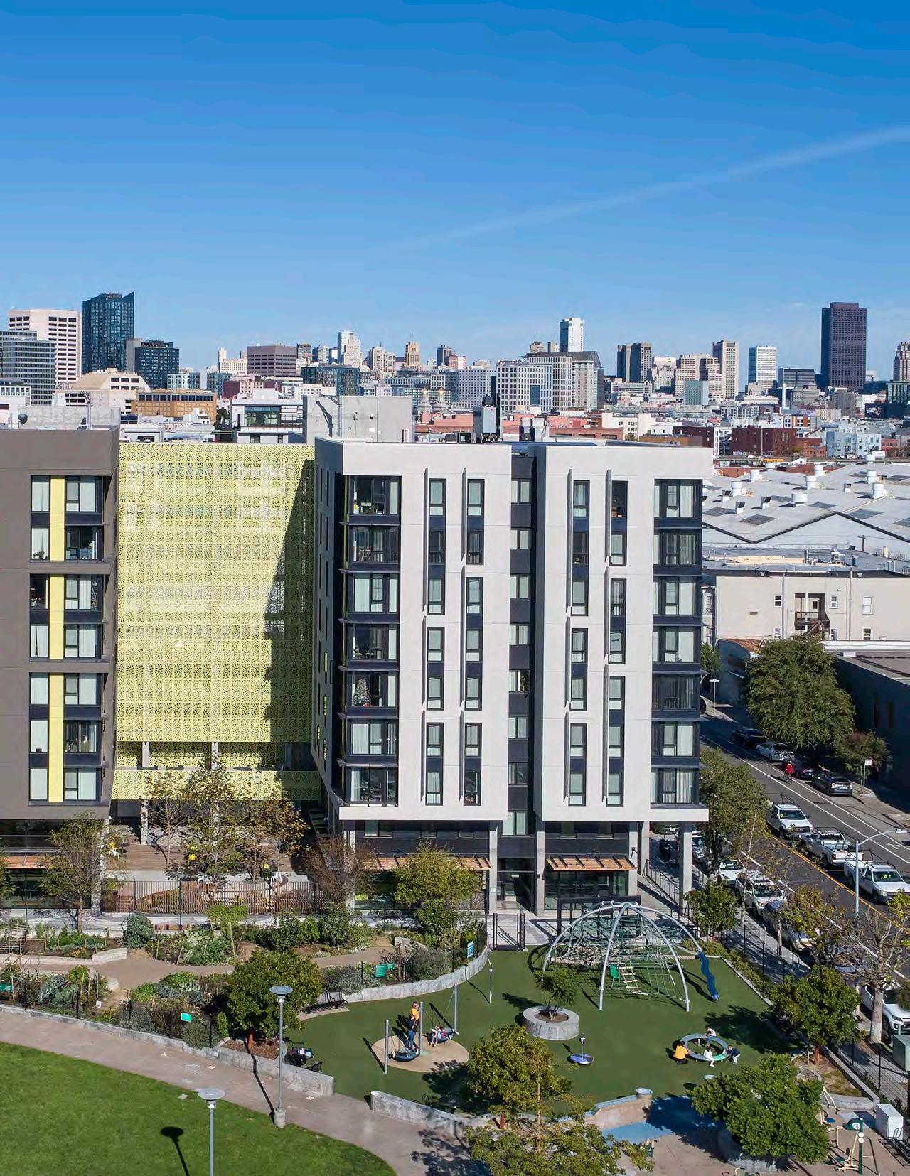
93
PHOTO: BRUCE DAMONTE
Casa Adelante at 2060 Folsom
Case Study No. 5
Data Summary
Project Type: Affordable Housing (New)
Location: San Francisco, CA
California Climate Zone: 3
Clientele: Low-Income Families
Gross Floor Area: 169,995 gsf
Fully Occupied: 2021
Modeled EUI (Site):
14.0 kBtu/sq.ft. per year
Measured EUI (Site): 18.6 kBtu/sq.ft. per year
On-Site Renewable Energy System Installed:
76.3 kW (DC) Solar PV
On-Site Storage Battery:
None
Measured On-Site Energy
Production:
115,900 kWh (9/2021-8/2022)
2.33 kBtu/sq.ft.-year
Owner/Client
Mission Economic Development Agency and Chinatown Community Development Ctr.
Design Team Architect:
Mithun, San Francisco Office
Y.A. Studio, San Francisco
Structural Engineer: Structus, Inc., San Francisco
Mechanical, Electrical and Plumbing Engineering: Integral Group (now Introba), Oakland
Landscape Architect
Mithun, San Francisco Office
Energy Code Consultant
AEA, San Francisco
Sustainability Consultant
Global Green, Santa Monica
General Contractor:
Roberts Obayashi, Danville
Solar Contractor:
Sun Light & Power, Berkeley
This final case study is the third affordable housing16 project treated in this book of all-electric multifamily housing projects. In this case, the housing serves a general population of low-income residents of the Mission District of San Francisco, primarily families17 and Transitional-Aged Youth (TAY)18. Whereas the two earlier case study projects are located in a rural and a suburban area, respectively, this third affordable housing project has an urban context and is a large multistory structure because of the density required. In this way, it differs from the other two in significant aspects, but there are similarities in the design solutions that make this an instructive case study.
Background
In the late 1990s, the traditionally working-class Mission District was undergoing significant community changes caused by the “dot-com boom”, which continued a few years later with the gradual influx of tech workers as the Internet underwent massive growth. The developing wave of high-tech offices and market-rate housing started to displace low-income residents and small businesses. In response, several non-profit organizations were formed to advocate for a community-based vision for the Mission neighborhoods and to influence planning decisions for those neighborhoods. Such neighborhood groups were formed to work on behalf of the current residents, many of whom were low-income, so that they would not be forced out by market developers building housing that would essentially gentrify the area.
The Mission Economic Development Agency (MEDA), for example, is such a community development organization that started a real estate development activity as a way to bring affordable housing to residents. MEDA uses the identifying branding term, “Adelante” (Spanish for “Forward”), in all its projects—thus the name of this particular case study project.
Another community organization, People Organizing to Demand Environmental and Economic Rights (PODER), advocates in particular for low-income Latino families and youth. Concerned generally for environmental justice, PODER focuses on issues of land use, community planning and affordable housing to nurture thriving neighborhoods in the Mission District.
Together, these two organizations were key contributors to the ultimate approval in 2011 of the first step of the affordable housing project at 2060 Folsom Street by the San Francisco Board of Supervisors, namely the land acquisition in the heart of the Mission District. As a result of this approval, two adjacent parking lots used by the San Francisco Public Utilities Commission (SFPUC) were turned over to the Mayor ’s Office of Housing and Community Development for use as a new neighborhood park and the site of the mid-rise affordable housing structure.
As an initial development phase, PODER worked in collaboration with the San Francisco Parks and Recreation Department on a community-led design process for the park, located on the south end of the site. This part of the project advanced ahead of the housing to open in June, 2017. The park was named In Chan Kaajal, (“My Little Village” in Mayan).
Meanwhile, the Mayor ’s Office of Housing and Community Development issued a competitive RFP for the affordable housing portion of the project. Since MEDA did not meet certain financial
16 The reader is referred to the summary discussion of affordable housing, in the introductory paragraphs of Case Study No. 1, Ivy Senior Apartments, p.4 of this monograph.
17 To qualify, families must be at 40% to 60% Area Median Income (AMI).
18 “TAY are young adults, ages 18-24 (and ages 25 to 27, for those experiencing homelessness) who are transitioning from public systems like foster care and are at risk of not making a successful transition to adulthood.” From Mayor’s Office of Housing and Community Development, SF.GOV.
94 CASE STUDY NO. 5 CASA ADELANTE AT 2060 FOLSOM Designing for Zero Carbon: Volume 2
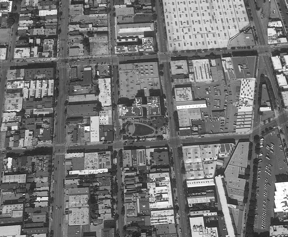
95 CASA ADELANTE AT 2060 FOLSOM CASE STUDY NO. 5 Designing for Zero Carbon: Volume 2
Casa Adelante at 2060 Folsom - General Vicinity Plan
Folsom Street
Shotwell Street South Van Ness Avenue
17th Street
16th Street
April 2016
November 2016
Designing for Zero Carbon: Volume 2
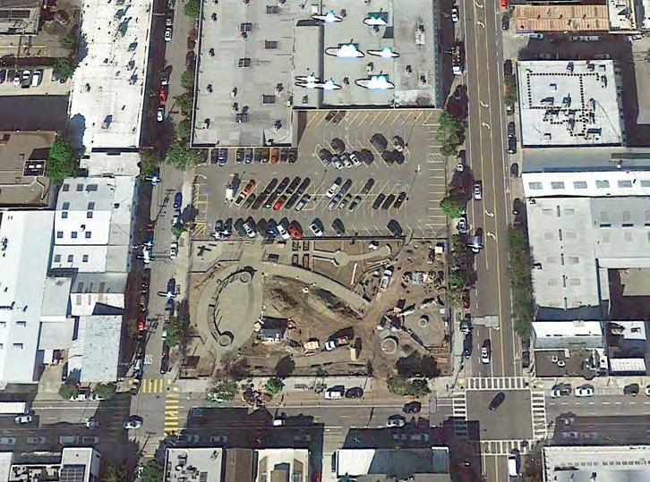
June 2019
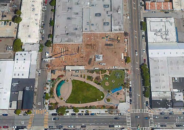
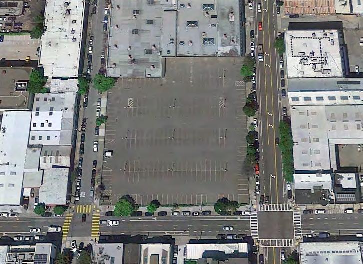
96 CASE STUDY NO. 5 CASA ADELANTE AT 2060 FOLSOM
(Left, Opposite Page) 2060

Folsom project site at different phases of construction: preconstruction (top), the park construction (middle) and the building construction (bottom). requirements as developer, the organization joined with the Chinatown Community Development Center (CCDC), forming a joint venture development team. CCDC also had significant management experience in the operation of such facilities and would go on to provide management services for the occupied facility.
MEDA and CCDC put together a project team that included the design and consulting firms, and submitted a complete project proposal consisting of a design proposal, a financial proposal and a community services proposal, as required by the RFP. The team was successfully awarded the project in the summer of 2015. Design and permitting for the structure required about three years and construction began in January 2019.
Design Process and Low-Energy, Zero-Carbon Design Strategies
Architectural firms sometimes hold a project kickoff session called a “process design charrette” for larger projects that involve multiple organizational clients. In this facilitated meeting, the entire project team discusses and establishes the project goals, a communications organization for the project team and benchmarks associated with a project schedule. The result is called a process design plan, which all project team members agree upon and commit to follow.
Modeled on this type of project kickoff event, a team-wide Green Charette was organized in late 2015, which included members of the entire project team, the Mayor’s housing office (as representative of the funding agency) and PODER (as representative of the community). This intensive and interactive meeting, facilitated by Walker Wells of Global Green19, resulted in a set of project goals, benchmarks, deliverables and a project schedule.
In fact, it was at this meeting that the idea of a zero-carbon design goal through an all-electric design was introduced, discussed and adopted. The decision to design an all-electric building was encouraged in part by the fact that the City of San Francisco already provides non-fossilfuel-based electric power through the services of the San Francisco Public Utilities Commission. Therefore, zero-carbon operation would be possible on the first day of building occupancy. In addition, an all-electric facility would require less space for equipment than one that is fossil-fuelbased, which would maximize the space efficiency of the building.
With the principal decisions about the project organization and process made, the team then proceeded to finalize the building program for the housing and the second half of the site.
19 Based in Santa Monica, California, Global Green USA is “partnered with EPE Sustainable Neighborhoods to develop policy change and sustainability impact for underserved communities in 29 US cities”. https://globalgreen.org/
(Left) Graphic designed by Mission Economic Development Agency (MEDA), the community organization in the Mission District that co-developed the project, as part of a presentation to explain their “motivations and considerations”.

97 CASA ADELANTE AT 2060 FOLSOM CASE STUDY NO. 5 Designing for Zero Carbon: Volume 2
Building Program / Site Constraints
The Mayor’s housing office required, as the result of discussions with all the neighborhood groups, a program that included not only apartments for the clientele, but also social services of various kinds at the ground floor level. These included office space for the local community organizations and resource centers, a childcare center, a community room and a neighborhood café.
As the building program was being finalized, the PODER organization negotiated an increase in the building height to accommodate more apartment units. Set at nine stories, just under the height limit beyond which the “high-rise” designation per the city code would apply, the final structure ultimately fit 127 one- to three-bedroom apartments in addition to the ground floor community space program.
No parking was programmed, allowing even better site utilization, saving excavation and below-grade construction costs that would have been necessary.
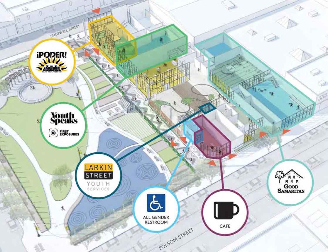
98 CASE STUDY NO. 5 CASA ADELANTE AT 2060 FOLSOM Designing for Zero Carbon: Volume 2
(Right, Opposite Page) The east-west “paseo” across the site, connecting the community services of the first and second levels of the building (on the right in photo) with In Chan Kaajal Park.
(Below) Spaces for local services and community resources are provided at the ground floor level.
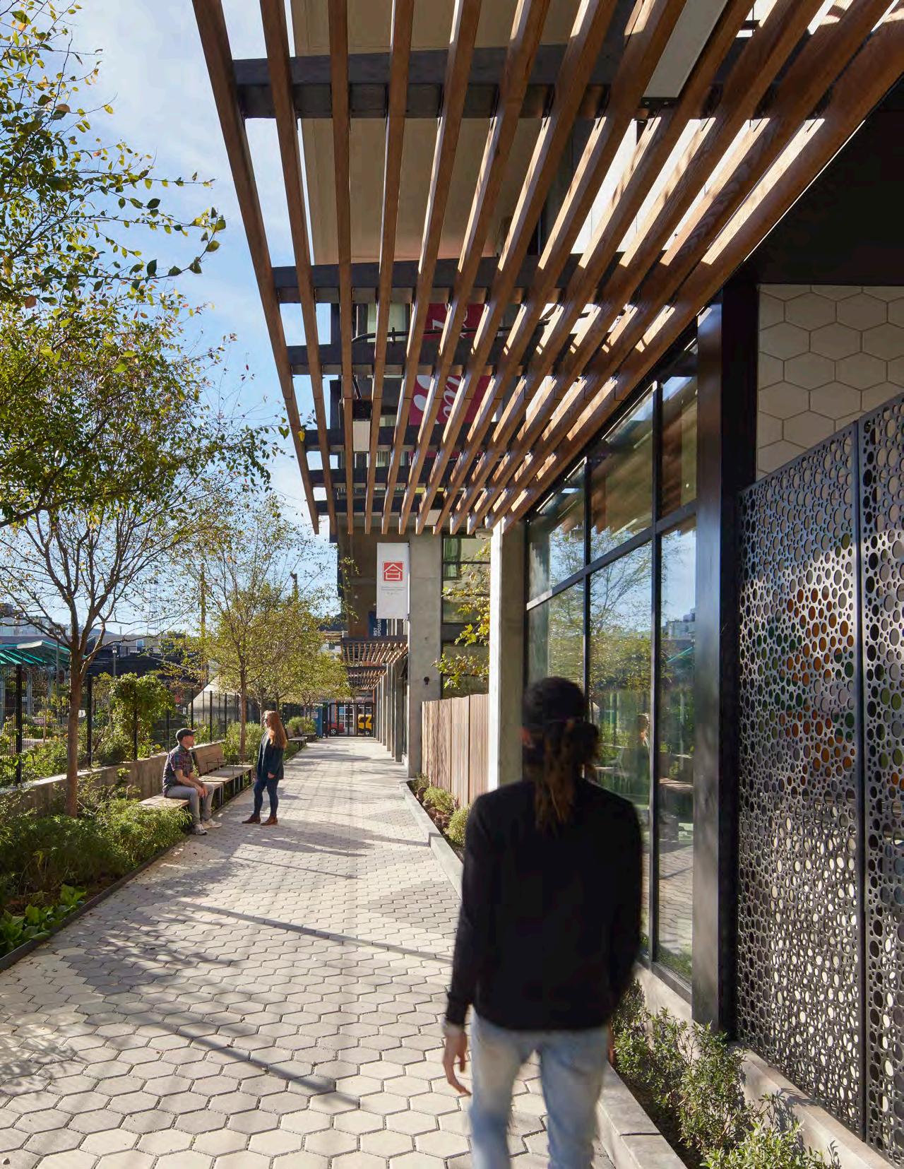
99
PHOTO: BRUCE DAMONTE
SECOND FLOOR PLAN
GROUND FLOOR PLAN
CASA ADELANTE - 2060 FOLSOM: FLOOR PLANS
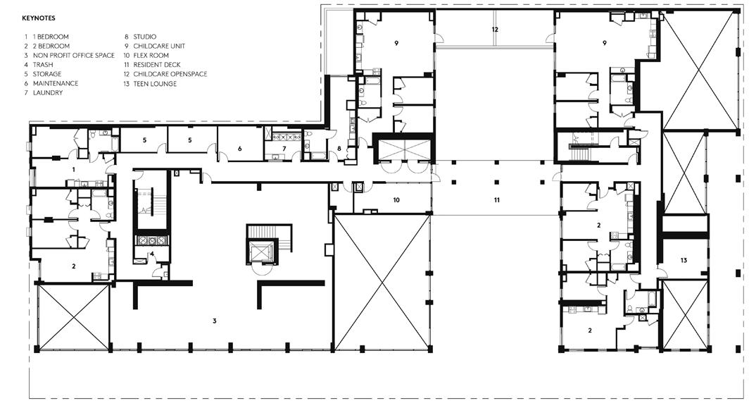
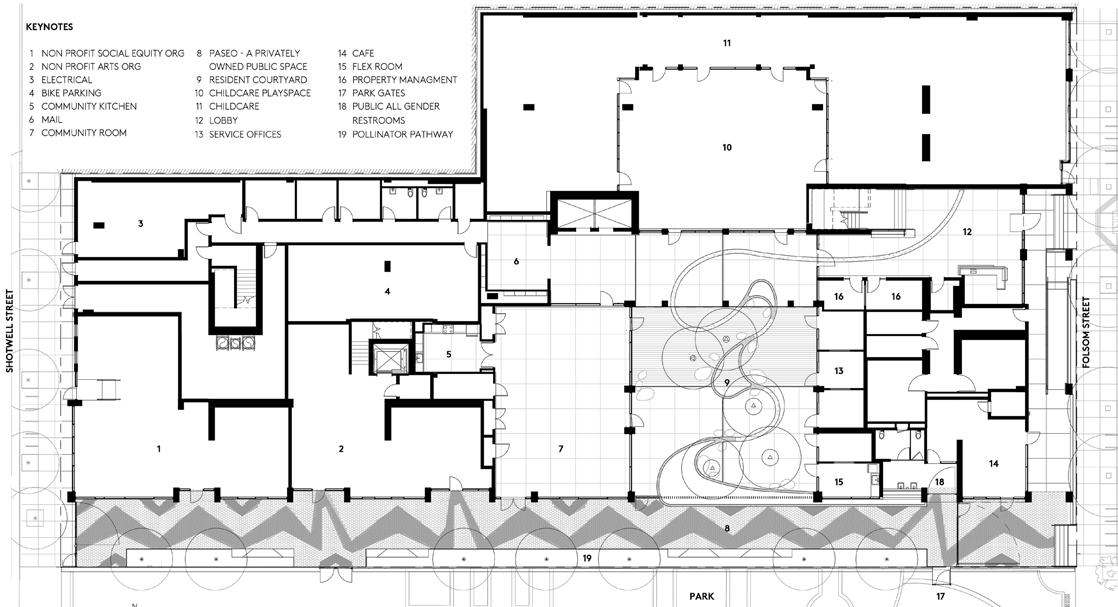
100 CASE STUDY NO. 5 CASA ADELANTE AT 2060 FOLSOM Designing for Zero Carbon: Volume 2
0 5 10 20 40 FT 0’ 2’ 4’ 8’ R A A B A A A A
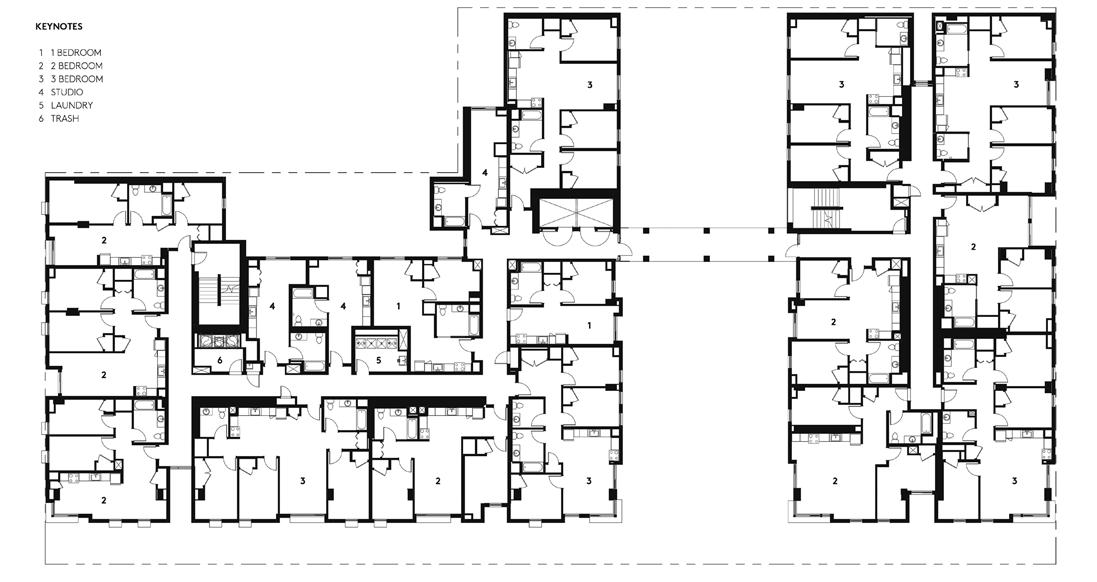

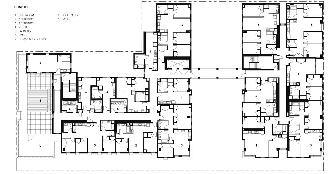
101 CASA ADELANTE AT 2060 FOLSOM CASE STUDY NO. 5 Designing for Zero Carbon: Volume 2 NORTH
3 - 7 FLOOR PLANS
A A A A
8 - 9 FLOOR PLANS
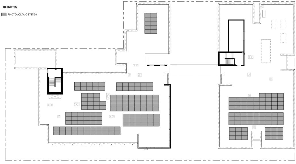
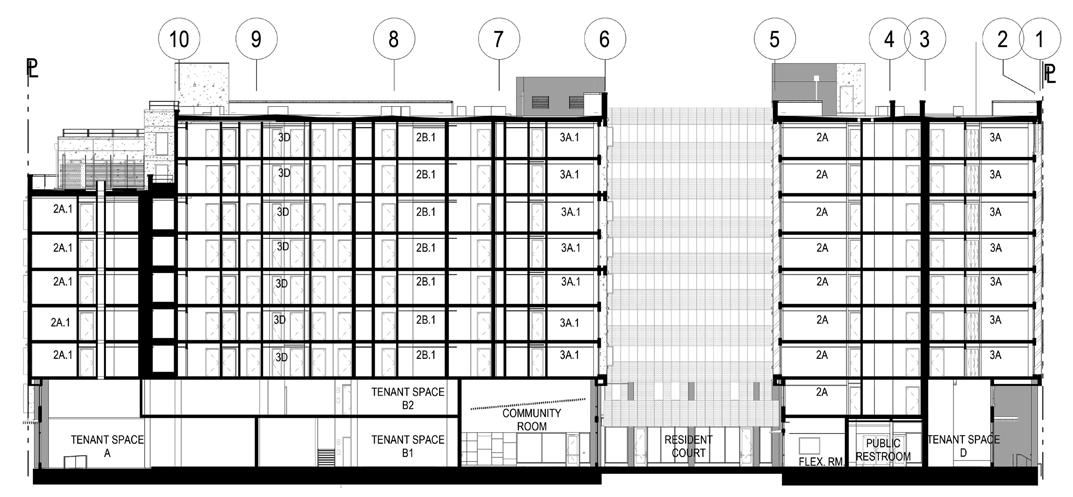
102 CASE STUDY NO. 5 CASA ADELANTE AT 2060 FOLSOM Designing for Zero Carbon: Volume 2 CASA ADELANTE - 2060 FOLSOM: ROOF PLAN AND BUILDING SECTION 0 5 10 20 40 FT 0’ 2’ 4’ 8’ R A B NORTH ROOF PLAN SECTION A-A A A
Building Envelope – Insulation and Windows
The nine-story concrete frame building uses non-combustible wall assemblies at the exterior walls, consisting of 2 x 6 metal stud framing with R-19 fiberglass batt insulation (formaldehydefree). To prevent thermal bridging, a layer of two-inch rigid polyisocyanurate insulation is applied over the outside of the framed wall. (See detail below.)
The concrete slab is uninsulated below or at its edges. The roof, however, is well insulated using a lightweight low-density insulating cellular concrete20 to provide both the slope required for drainage and an average thickness of six inches to achieve R=30.
For basic cost reasons, the windows are standard double-glazed metal frame windows, with a U-value of 0.25 and a Solar Heat Gain Coefficient (SHGC) equal to 0.25.
Building Envelope – Airtightness
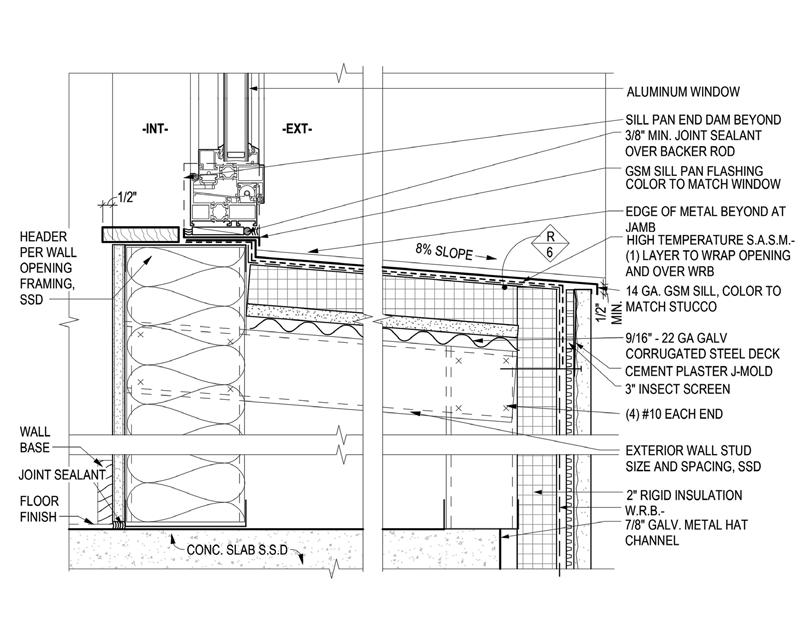
No special airtightness measures were taken. Additional systems would be required, which would have incurred additional cost.
20 Elastizell™ Systems Inc., https://www.elastizell-systems.com/roof-deck.php
103 CASA ADELANTE AT 2060 FOLSOM CASE STUDY NO. 5 Designing for Zero Carbon: Volume 2
(Left) Representative wall detail showing the two-inch layer of rigid polyiso insulation applied to the wall surface to prevent thermal bridging at the metal studs.
Heating, Ventilating and Cooling Systems
The heating and cooling of each apartment is carried out by an independent system for each unit, as opposed to a centralized system that serves multiple apartments. The temperate climate and the energy-efficient design of the building envelope (well-insulated walls and window shading) minimize the cooling loads as well as the heating loads As a result, there is no need for mechanical cooling via a heat pump system, which ordinarily would be used.
For heating, each unit has electric resistance heaters, which are located in ceiling coves.21 This was the least expensive option. In addition, electric resistance heaters are easily maintained and replaced at minimal cost. The ceiling location was chosen rather than floor-level baseboard in order to avoid potential blockage by furniture and the resultant inefficiency or potential damage. Furthermore, the high-quality building envelope in the marine climate of San Francisco minimized the normal thermal comfort advantage of floor-mounted heaters below windows.
Although mechanical cooling is not utilized, in order to ensure good indoor air quality and fresh air supply, each individual apartment is supplied with a Heat Recovery Ventilator (HRV) system22 The HRV system not only provides heat recovery during the heating season, but can be used for night ventilation cooling when needed. The night flush operation precools the concrete structure for the next day during rare times of peak weather events.
The HRV is either in “heat recovery mode” or “bypass mode”. It is always operating silently. Fresh air is always entering the unit through the HRV air intake. Normally, if heating is required, the heat recovery mode is operating and the windows would be closed. If neither heating nor cooling is required, windows can be opened if the electric resistance heaters are turned off.
When the kitchen fan or bathroom fan is turned on by the occupant, the HRV switches into bypass mode and its internal exhaust shuts off. The kitchen or bathroom fan then becomes the exhaust route of the incoming fresh air. (The bathroom fan is always operating at a low exhaust level but the occupant only hears the bathroom fan when the bypass fan switch is engaged.)
Because each apartment has its own HRV system, the air exhausts only through the adjacent building façade. A large mechanical unit serving many apartments would require exhaust ducts to the roof, with fire dampers and an emergency generator to maintain the air exhaust. All this is avoided if the air system is contained in a single apartment, thereby saving extra costs and loss of floor space. Furthermore, using the individual HRV units means that the use of shared ductwork between apartments is avoided, which prevents a possible migration of insects and other pests.
Two conventional air-source heat pumps23 are used for the common spaces on the first two levels of the building. These are DOAS systems24 with Variable Refrigerant Flow (VRF)25. One system serves the ground-floor spaces plus the child-care center on the second floor The second system serves the remaining tenant common spaces on the second floor.
21 King KCV1202 cove heater
22 Zehnder ComfoAir 350-R
23 Mitsubishi PUZ-A30NHA7
24 For a description of a DOAS system, see: https://en.wikipedia.org/wiki/Dedicated_outdoor_ air_system
25 VRF works well in heat pumps for heating and cooling in buildings. See: https://en.wikipedia. org/wiki/Variable_refrigerant_flow
104 CASE STUDY NO. 5 CASA ADELANTE AT 2060 FOLSOM Designing for Zero Carbon: Volume 2
WARM EXHAUST AIR FROM BATHROOM AND KITCHEN - IN
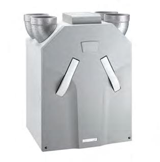
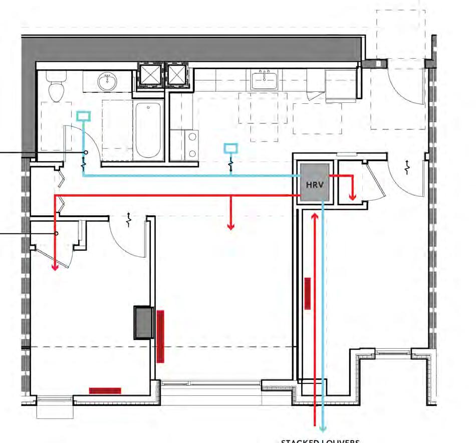
PREHEATED FRESH SUPPLY AIR - OUT
STACKED LOUVERS: LOW FRESH AIR INTAKE HIGH EXHAUST
105 CASA ADELANTE AT 2060 FOLSOM CASE STUDY NO. 5 Designing for Zero Carbon: Volume 2 14
HRV
(Above) Diagram of the HRV system layout in a typical twobedroom apartment.
(Left) HRV heat exchange unit installed in each apartment, with incoming and outgoing air duct connections.
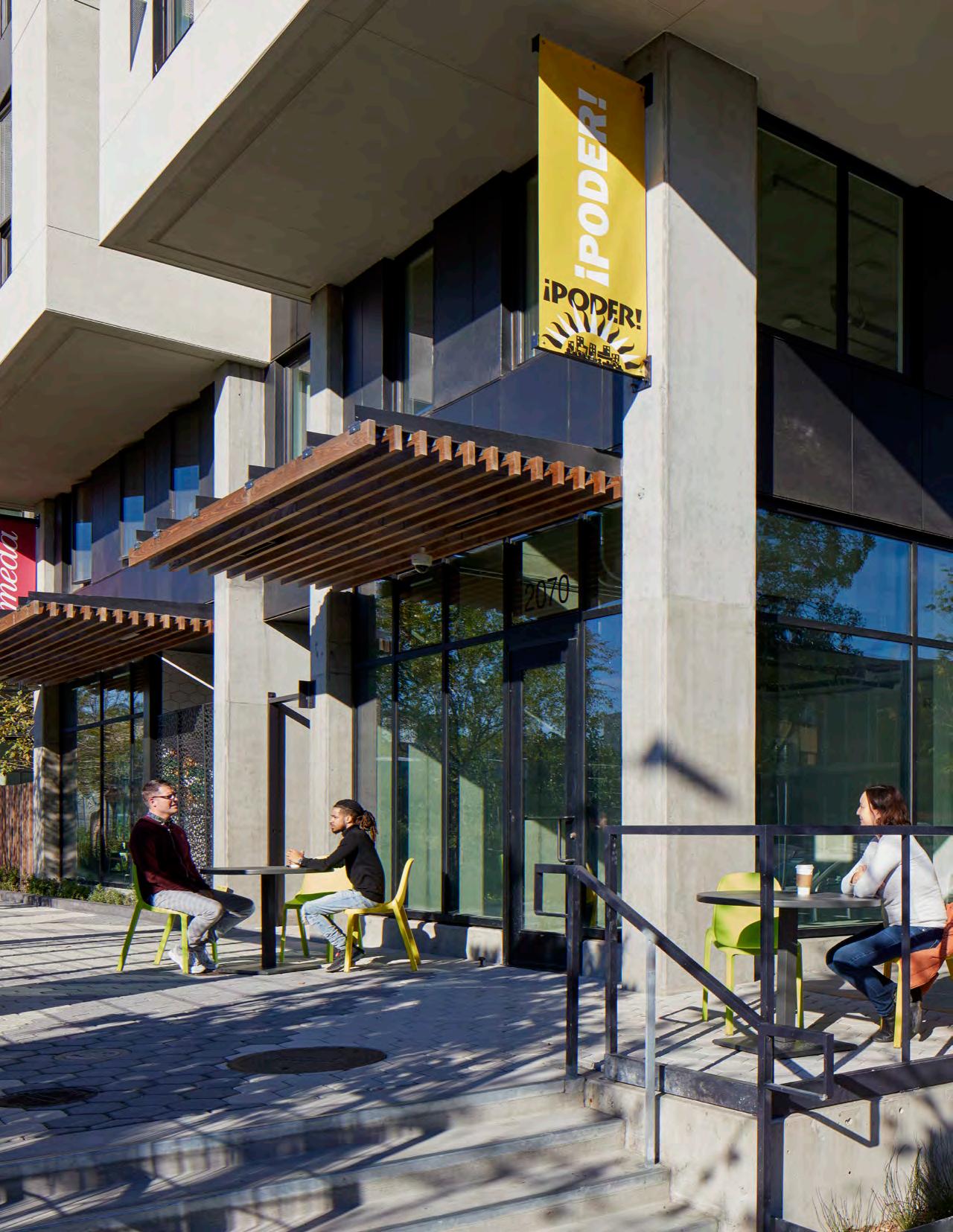
106
PHOTO: BRUCE DAMONTE
Domestic Hot Water Systems
There is a large central heat pump water heating system for the entire building.26 Initially, a solar thermal system was required27, but the project team secured an approval of an Alternate Materials and Methods Request (AMMR) and the solar thermal system was eliminated from the central heat pump water heating system. Experience with a similar project showed that solar thermal systems paired with heat pumps for water heating caused the efficiency of the heat pumps to drop significantly since the incoming water from the solar thermal system was too warm.
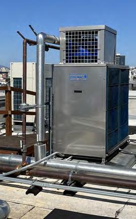
Appliances
Each kitchen is equipped with an electric resistance range with ceramic tops. Induction ranges were not specified because the unit price was significantly higher and the client understood that the tenants would be unfamiliar with the characteristics and requirements of induction cooking.
Lighting, Plug Loads and Control Systems
Energy-efficient LED light sources are employed with automatic dimming in response to daylight levels in the room. Control of lights by occupancy sensors provide additional energy-efficient operation of the lighting systems.
On-Site Energy Storage: Batteries
Electric energy is provided by the city-owned public utility, Hetch Hetchy Power. There is no rate structure applicable to this project where there would be an advantage to store energy generated by the solar PV system for use at a later time.
However, one of the client organizations, the CCDC, requires an emergency electric power backup system in all of its projects since most of its projects are senior housing. Since at the time of construction, the City of San Francisco prohibited battery backup for emergency elevator egress, the CCDC requirement resulted in the installation of a diesel generator. (The City of San Francisco and the CCDC have since modified this requirement—batteries are now permitted.)
EV Charging
Normal city parking requirements were waived for this project. Therefore, there is no car parking on the site and no corresponding provision for an EV-charging infrastructure.
26 Colmac HPA 15-PDAC PLC
27 See Case Study No. 1, Ivy Senior Apartments, p. 17, for additional discussion of this issue.
107 CASA ADELANTE AT 2060 FOLSOM CASE STUDY NO. 5 Designing for Zero Carbon: Volume 2
(Above) Heat pump water heater located on the roof.
(Left, Opposite Page) Community cafe at the building corner adjacent to the paseo and In Chan Kaajal Park.
Renewable On-Site Energy Supply
Solar Photovoltaic System
Since the nine-story building covered the entire site, the only space available for a solar photovoltaic system was the limited area of the roof. Even after accommodating the space requirements of the mechanical equipment such as the heat pump water heaters and the diesel generator, however, the designers fit a system consisting of 212 Sunpower16 panels into the space available, for a total installed 76.3kW. (See Roof Plan on p.102 and drone photo below.)
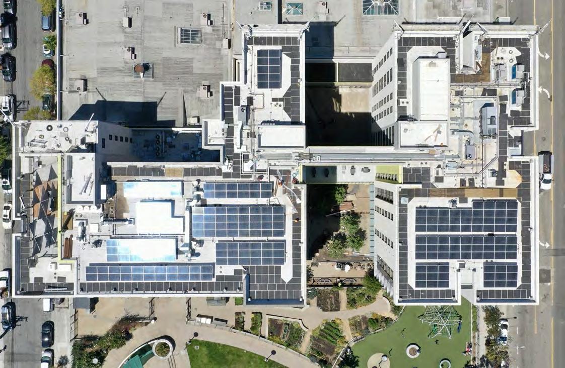
The solar photovoltaic system generates electricity that is sent into the utility grid and is metered separately from the energy loads of the building. This energy is credited as an offset to the building’s electric charges for the energy used in the common spaces and by the domestic hot water heat pump that serves the building as a whole. The utillity meters that record the energy used by all the spaces in the building are separate from that recording the energy produced by the solar PV system.
Sub-metering the building space energy use allows the building management to allocate some fraction of the utility charge to each tenant as appropriate.
16 Sunpower X22-360-COM, 360W, Monocrystalline.
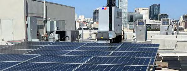
108 CASE STUDY NO. 5 CASA ADELANTE AT 2060 FOLSOM Designing for Zero Carbon: Volume 2
Design Analysis: Optimizing Zero-Carbon Design
Design Analysis: Embodied Carbon
In contrast to the previous case study projects in this volume, the design requirements of the 2060 Folsom multifamily residential building motivated the project team to seek embodied carbon reductions from a normally conventional approach to the structural design and materials selection. One such instance resulted from the design objective of increasing the building height to create the maximum floor area that fits just under the code definition of “high-rise”. This would create a nine-story building design on a site where poor soil conditions already required that a significant amount of concrete to be added at the foundations. The amount of embodied carbon resulting from this large amount of added concrete would be high. Therefore, the project team set a design task to find some low-carbon alternatives for the building materials, including for non-structural components.
Using a Life Cycle Assessment (LCA)17 analysis, the design team found (unsurprisingly) that the large amount of concrete required for the extra foundation work was the main generator of high embodied carbon content. In addition, the analysis showed that the quantity of finished interior walls, typical of large multifamily projects, resulted in an unusually high use of gypsum board finish material, a carbon-intensive material.
The solution adopted for reducing the embodied carbon of the concrete was to optimize the concrete mixes for structural strength, while reducing the cement content and substituting supplementary low-carbon cementitious materials. In the case of the gypsum board and similar finish materials, the designers specified products with lower embodied carbon content and simply left the structure exposed where possible, adopting a “structure-as-finish” design approach.
The result, as shown in the final LCA analysis, was a Global Warming Potential (GWP)18 of 397, compared with the design team’s previous multifamily housing projects of similar size and construction where the GWP numbers were in the range of 500-525. (See the chart of the GWP analysis for this case study project on the next page, with the breakdown by the caregory of material used in the final construction.)
17 See Sidebar: Embodied Carbon Assessment on the next page for a description of LCA.
18 GWP is a building rating of its total embodied carbon. See Sidebar: Embodied Carbon Assessment for how this rating is determined.
109 CASA ADELANTE AT 2060 FOLSOM CASE STUDY NO. 5 Designing for Zero Carbon: Volume 2
Sidebar: Embodied Carbon Assessment - Integrating into the Design Process
Embodied carbon in a building refers to the greenhouse gas emissions associated primarily with the extraction and manufacturing of materials used for the construction of the building. It also includes carbon generated by the smaller effects of transportation to the building site, construction processes and disposal of materials at demolition (“end-of-life”). “Disposal” can also mean deconstruction, salvage or reuse.
Operational carbon in a building refers to the greenhouse gas emissions associated with the energy use in the operation of the building in its lifetime. As energy efficiency in buildings increases and renewable energy sources replace fossil fuel sources, the total operational carbon will gradually be minimized and embodied carbon will become the focus of significantly reducing carbon emissions in the building sector.
Embodied carbon reduction is primarily accomplished by choosing the materials and building systems with lowest carbon emission quantities due to raw material extraction, manufacturing and shipping to the building site, while satisfying the particular design requirements of the building. During the design phase, alternative design choices can be compared for embodied carbon quantities. Embodied carbon can also be minimized by extending the life of existing buildings through reuse and renovation, rather than building a new project, as with the Vera Cruz Village project (Case Study No. 3 in this monograph).
Units of embodied carbon quantities are typically metric: kg CO2, or kilograms of carbon dioxide. Note: for greenhouse gases other than carbon dioxide, the unit of measurement is kg CO2eq, where CO2eq is “carbon dioxide equivalent”. For example, if methane is emitted in the process of making the product, the number of kilograms is multiplied by 27.9 to calculate the equivalent to that mass of embodied carbon in the material for its global-warming effect. In buildings, the standard unit of embodied carbon is 1 kg CO2eq per square meter of floor area, or as it is usually written, 1 kgCO2eq/m2 16
The calculated total of kgCO2eq/m2 for a building is labelled “GWP” for “Global Warming Potential”. This GWP number serves as a measure of the embodied carbon “rating” for the building, in the same way the EUI is the energy use “rating” for the building. The case study project, 2060 Folsom, was calculated to have a GWP = 397. This is lower than similar recent structural concrete projects designed by the same architectural firm, Mithun, and the lower GWP is due primarily to the optimization of concrete mixes to limit cement content, minimizing the use of gypsum wallboard material (still the 4th-most carbon intensive material in the project because of the high volme of interior partitions in the multifamily program) and attention to the finish materials which are, where used, lower embodied carbon than market average.
The methodology of comparison of environmental impacts of design or material alternatives is called Life Cycle Assessment (LCA). LCA software uses built-in datasets of materials and embodied carbon information to evaluate all component parts of a building model. Tally17 is currently most used by design professionals as a plug-in software package for the Revit BIM software. Material quantity inputs for the LCA analysis are obtained directly from the Revit model of the building.
The graphs below display the embodied carbon content for the 2060 Folsom case study building as measured by the calculated GWP.18 The Tally analysis is summarized by both the Revit component category and by specification division. The software provides an even more refined breakdown within each major component/division, allowing an understanding of the effect on the embodied carbon of changing a single product specification. Such detailed analysis resulted in design choices that produced the low GWP of 397.
16 “Embodied Carbon Benchmark Study - LCA for Low Carbon Construction”, The Carbon Leadership Forum, The University of Washington, p.56, Appendix B: Methodology, (February 2017)
17 Tally, Autodesk, https://choosetally.com/overview/
18 Tally analysis data courtesy of the San Francisco office of Mithun
110 CASE STUDY NO. 5 CASA ADELANTE AT 2060 FOLSOM Designing for Zero Carbon: Volume 2
0 50 100 150 200 250 300 350 400 450 500 GWP (kgCO2eq/m2) Embodied Carbon Division/Tally Entry 03 - Concrete 04 - Masonry 05 - Metals 06 - Wood/Plastics/Composites 07 - Thermal and Moisture Protection 08 - Openings and Glazing 09 - Finishes 0 50 100 150 200 250 300 350 400 450 500 GWP (kgCO2eq/m2) Embodied Carbon Revit/Tally Category Ceilings Curtainwall Mullions Curtainwall Panels Doors Floors Roofs Stairs and Railings Structure Walls 0 50100150200250300350400450500 GWP (kgCO2eq/m2) Embodied Carbon Revit/Tally Category Ceilings Curtainwall Mullions Curtainwall Panels Doors Floors Roofs Stairs and Railings Structure Walls 0 50 100 150 200 250 300 350 400 450 500 GWP (kgCO2eq/m2) Embodied Carbon Division/Tally Entry 03 - Concrete 04 - Masonry 05 - Metals 06 - Wood/Plastics/Composites 07 - Thermal and Moisture Protection 08 - Openings and Glazing 09 - Finishes 0 50 100 150 200 250 300 350 400 450 500 GWP (kgCO2eq/m2) Embodied Carbon Division/Tally Entry 03 - Concrete 04 - Masonry 05 - Metals 06 - Wood/Plastics/Composites 07 - Thermal and Moisture Protection 08 - Openings and Glazing 09 - Finishes 0 50 100 150 200 250 300 350 400 450 500 GWP (kgCO2eq/m2) Embodied Carbon Revit/Tally Category Ceilings Curtainwall Mullions Curtainwall Panels Doors Floors Roofs Stairs and Railings Structure Walls Average of Multifamily Projects Utilizing Structural Concrete Designed by Mithun prior to 2060 Folsom
Design Analysis: Energy Modeling and Operational Carbon
Energy modeling was carried out for the nine-story design using IES-VE software. The building was modeled as a whole, combining the energy use by the apartments with the common spaces on the first and second levels of the building. The modeled energy use on a monthly basis for a typical year is given in the chart below. The results of the modeling show that the building would consume 696 MWh and was predicted to have an EUI = 14.0.
The annual energy production of the solar PV system was not modeled since the installation space was so limited.
Modeled Monthly Energy Use
Modeled Monthly Energy Use
695,820 kWh/year
Modeled EUI = 14.01

111 CASA ADELANTE AT 2060 FOLSOM CASE STUDY NO. 5 Designing for Zero Carbon: Volume 2
0 20,000 40,000 60,000 80,000 100,000 120,000 Sep Oct NovDec Jan FebMar Apr May JunJul Aug kWh

112 CASE STUDY NO. 5 CASA ADELANTE AT 2060 FOLSOM Designing for Zero Carbon: Volume 2 0 10,000 20,000 30,000 40,000 50,000 60,000 Sep Oct NovDec Jan FebMar Apr May JunJul Aug kWh Solar Photovoltaic System Performance (2021 - 2022) Measured Energy Use (Apartments Only) Measured Energy Production (Solar PV System) 2021 2022 Solar Photovoltaic System Performance (2021-2022) Measured Monthly Energy Use (2021-2022) 0 20,000 40,000 60,000 80,000 100,000 120,000 Sep Oct NovDec Jan FebMar Apr May JunJul Aug kWh Measured Monthly Energy Use (2021 - 2022) 2021 2022 925,711 kWh/year Measured EUI = 18.63
Energy Performance and Operational Carbon: Post-Occupancy Measurement
Energy Use — Post-Occupancy Measurement
There are two electric utility meters recording energy use by the entire building. One meter specifically records the energy use in the 126 apartments and the second meter measures the electric energy use in the rest of the building areas. The energy produced by the solar PV system is separately metered and transmitted to the public utility grid. The building management company is responsible for all energy charges, which are determined from these three public utility meters.
Each apartment is locally metered for its energy use by the management company. The tenant pays for a portion of this with the monthly apartment rent charge, which is subsidized for an amount determined by formula for each tenant.
The actual electric energy used in the entire building, as measured by the two meters, is shown in the chart on the opposite page (top). The building consumed 926 MWh in the period of 9/2021 through 8/2022 and had an EUI = 18.6. The apartment meter recorded an annual energy use during that period of only 496 MWh—slightly more than half of the total building consumption— even though the apartments constitute more than 60% of the conditioned floor area.
Energy Production versus Energy Use
The aggregate total of energy used by all the apartment units on the project site is usefully compared to the on-site renewable energy generated by the solar PV system. This comparison is shown in the graph on the opposite page (bottom). The solar PV system provided 115,900 kWh during the period of 9/2021 - 8/2022. This total offset almost 25% of the energy used by the apartments during this same period, which was about 12% of the whole building’s energy use.
Post-Occupancy: Observations and Conclusions
The client team reported a challenge in negotiating some details of the energy costs associated with the energy supplier, Hetch Hetchy Power, which provides power to the City of San Francisco, and the public utility, Pacific Gas and Electric Company (PG&E), which provides distribution services within the city boundaries.
The design team based the design approach for heating and cooling on the conventional assumption that the marine climate of San Francisco means space cooling can be accomplished by relying on unconditioned outside air. There is some concern that long-duration heat events due to climate change may require adjustment or modification of the apartment systems.
(Next page, Top)
Second-floor common deck.
(Next page, Bottom)
The shared courtyard on the ground floor.
113 CASA ADELANTE AT 2060 FOLSOM CASE STUDY NO. 5 Designing for Zero Carbon: Volume 2
PHOTOS: BRUCE DAMONTE
Designing for Zero Carbon: Volume
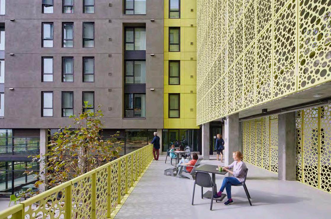
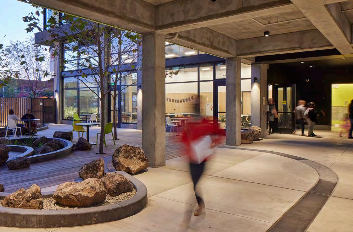
114 CASE STUDY NO. 5 CASA ADELANTE AT 2060 FOLSOM
2 114
Case Studies of All-Electric Multifamily Residential Buildings
115
Conclusion
Epilogue
Additional Exemplary All-Electric Multifamily Residential Projects
The case studies detailed in the preceding section are a group of all-electric multifamily projects with characteristics of energy efficiency and low-carbon effect as documented by operational data and analysis. These case study projects were selected for this publication from a long list of similar projects in California. It is worth noting these other projects throughout the state that are exemplary in their design and demonstrate the widespread application of this design approach.
The projects shown on the following pages are other exemplary multifamily residential projects that have been recently completed or under construction, both new and renovated structures, that were designed with all-electric energy systems. These additional projects have a particularly unique aspect of their program, building structure or financial constraints that make them especially noteworthy. They are shown in a one-page summary for each, so the reader can seek further information, if desired.
The list below of all the candidate projects for this case study publication provides the name and location of each, while the California map on the opposite page illustrates their wide distribution thoughout the state.
Case Study Projects:
Other Noteworthy Projects:
16. Magnolia Villas, Santa Monica
17. Crestview Terrace, San Bernardino
18. Keeler Court Apartments, San Diego
19. Spring Lake, Woodland

20. Heritage Square Senior Apartments, Pasadena
21. St. Paul’s Commons, Walnut Creek
22. Alta Madrone Apartments, Sonoma
23. Stoddard West Apartments, Napa
24. Everett Commons , Alameda
25. Church Hill Townhomes, Fortuna
26. Aster Place, Eureka
27. Yarrow Village Apartments, Fortuna
28. 18th Street Apartments, San Francisco
29. Gardena Place, Gardena
30. Rosewood Village Townhomes, Commerce
31. Parkridge Townhomes, La Mesa
32. Station House Townhomes/Condominiums, Oakland
33. Blossom Hill Townhomes/Condominiums, Oakland
34. Ice House Townhomes/Condominiums, Oakland
35. Ascend at Hamilton Field, Novato
36. Second Street Studios, San Jose
37. Plaza Point, Arcata
38. Napa Creek Village, Napa
39. Culver City Senior Housing, Culver City
40. Arrowhead Gardens, San Bernardino
41. Creamery Row Townhomes, Arcata
42. The Knolls at the Avenida, Atascadero
43. Kendrea Terrace Apartments, McFarland
44. Colonial House Apartments, Oxnard
45. Bandar Salaam Apartments, San Diego
46. Boyd Street Family Apartments, Santa Rosa
47. Amaya Village Apartments, Orange Cove
48. Eastgate Apartments, San Marcos
49. Sunrise Senior Apartments, Hollister
50. Paseo Pointe Apartments, Vista
DESIGNING FOR ZERO CARBON, VOL. 2 EPILOGUE 116 Case Studies of All-Electric Multifamily Residential Buildings
Ivy Senior Apartments, San Diego
Rosecrans Place, Gardena
Vera Cruz Village, Richgrove
Palo Alto Apartments, Palo Alto
Casa Adelante—2060 Folsom, San Francisco
(See this Epilogue section)
Coliseum Place,
McEvoy and Dupont Apartments, San Jose
Cedar Springs Apartments, La Verne
Hollywood Palms II, San Diego
Pacific Landing Apartments, Santa Monica
Walnut Place Townhomes, Gardena
Edgewood Point Townhomes, Long Beach
Edwina Benner Plaza, Sunnyvale
Quetzal Gardens, San Jose
1.
2.
3.
4.
5.
Additional Featured Projects:
6. Maceo May Apartments, San Francisco 7.
Oakland 8.
9.
10.
11.
12.
13.
14.
15.
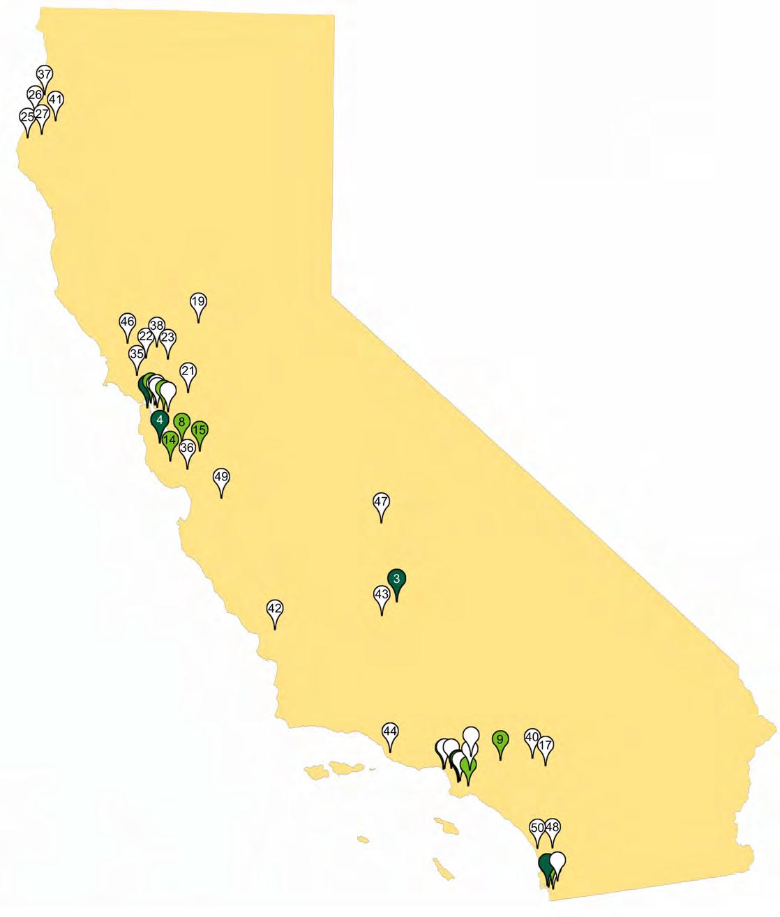


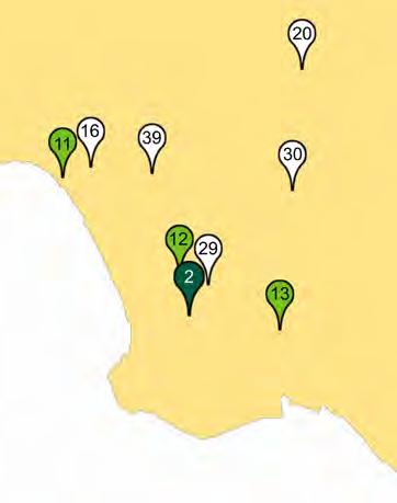
EPILOGUE DESIGNING FOR ZERO CARBON, VOL. 2 117 Case Studies of All-Electric Multifamily Residential Buildings
Project Team
Client:
Swords to Plowshares / Chinatown Community Development Center
Architect:
Mithun/Solomon
MEP Engineer: Engineering 350
Energy Modeling Consultant:
Association for Energy Affordability, Emeryville
Modeled EUI (Site)
17.8 kBtu/sf-year
Modeled Annual Energy
Use:
593,700 kWh
Measured EUI (Site)
Not yet available
On-Site Renewable Energy System Installed
83.6 kW(DC) Solar PV
Measured On-Site Renewable Energy Production
Not yet available
Maceo May Apartments, San Francisco Affordable Housing for Formerly-Homeless Veterans
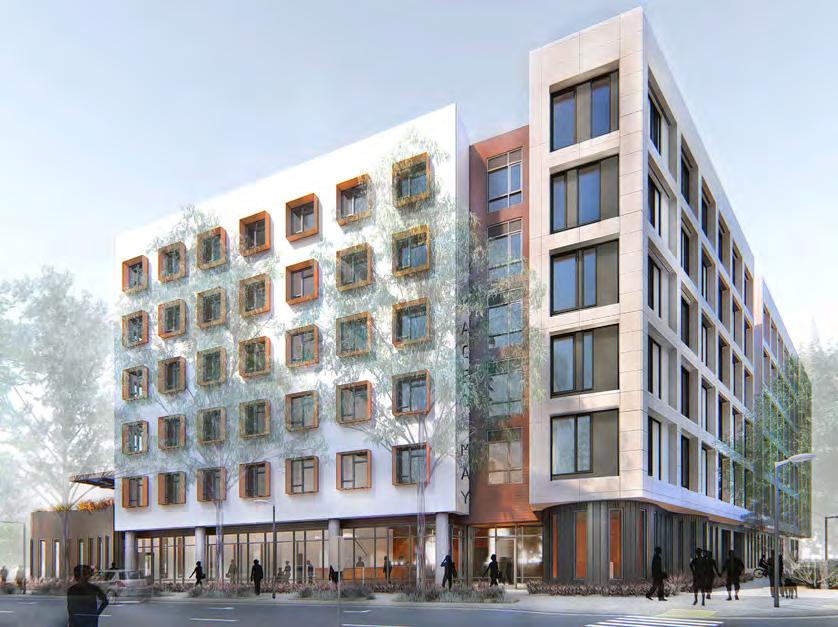
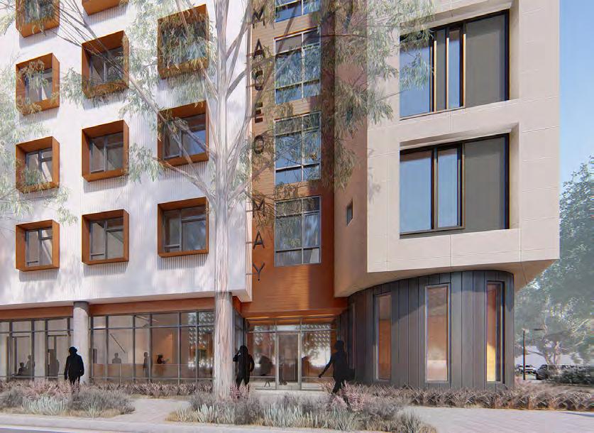
Number of Floors: 6
Gross Floor Area: 113,836 gsf
Fully Occupied: February 2023
Number of Units: 105 - 24 Studios, 47 (1BR), 34 (2BR)
Heating / Cooling System: Each apartment: electric resistance wall heater and an ERV / no cooling. Common rooms: heat pump with variable refrigerant flow (VRF)
DHW System: Heat pumps in a centralized DHW system, with three storage tanks and full building recirculation.
DESIGNING FOR ZERO CARBON, VOL. 2 EPILOGUE 118 Case Studies of All-Electric Multifamily Residential Buildings
Coliseum Place, Oakland, CA
Number of Floors: 6
Gross Floor Area: 71,512 gsf
Fully Occupied: April 2022
Affordable Housing for Low-Income Tenants
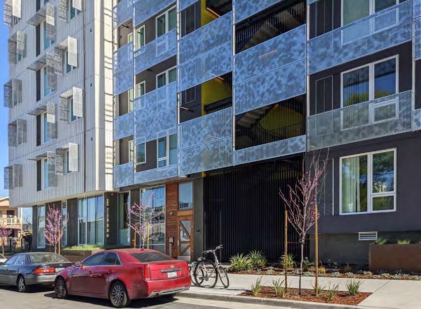
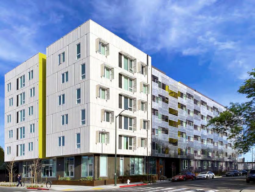
Number of Units: 59 - 11 (1BR), 28 (2BR), 20 (3BR)
Heating / Cooling System: Vertical Terminal Air Conditioners (VTAC) and Heat Recovery
Ventilators (HRV) in each unit
DHW System: Single shared system using two “mini-plants” per floor, each consisting of three heat pump water heaters, each of which serve 1-2 units.
Project Team
Client:
Resources for Community Development
Architect: David Baker Architects
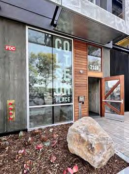
MEP Engineer: Energy Design Collaborative
Energy Modeling Consultant: Redwood Energy, Arcata
Modeled EUI (Site) 17.0 kBtu/sf-year
Modeled Annual Energy Use:
343,095 kWh
Measured EUI (Site)
Not yet available
On-Site Renewable Energy System Installed 98.6 kW(DC) Solar PV
Measured On-Site Renewable Energy Production
Not yet available
EPILOGUE DESIGNING FOR ZERO CARBON, VOL. 2 119 Case Studies of All-Electric Multifamily Residential Buildings
Project Team
Client:
First Community Housing, San Jose, CA
Architect: SERA Architects, Oakland
MEP Engineer: PAE, San Francisco Energy Modeling Consultant: PAE, San Francisco
Modeled EUI (Site)
8.27 kBtu/sf-year
Modeled Annual Energy
Use:
2,160 MWh
Measured EUI (Site)
Not yet available
On-Site Renewable Energy System Installed
40 kW(DC) Solar PV
Measured On-Site Renewable Energy Production
Not yet available
McEvoy and Dupont Apartments, San Jose Affordable Housing for Low-Income Tenants
Number of Floors: 13
Gross Floor Area: 306,000 gsf
Fully Occupied: Project currently on hold at pre-construction due to cost escalation.
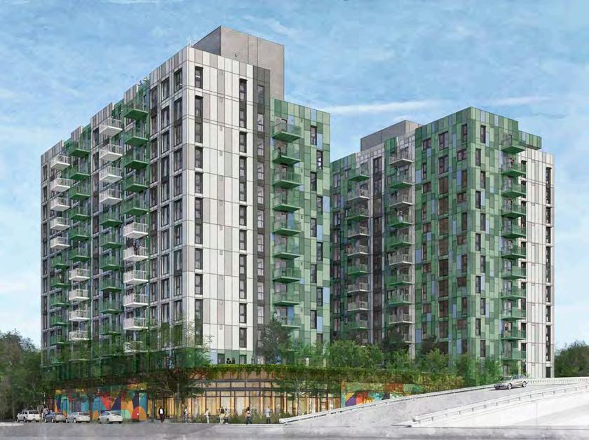
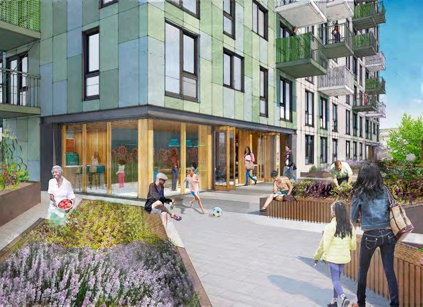
Number of Units: 365 - 142 Studios, 141 (1BR), 36 (2BR), 46 (3BR)
Heating / Cooling System: Central water-source heat pump system with ducted outside air tempered by refrigerant coils for heating or cooling.
DHW System: Central water-source heat pump system with standard distribution system.
Special Features: Mass Timber Construction, Very Low Embodied Carbon
DESIGNING FOR ZERO CARBON, VOL. 2 EPILOGUE 120 Case Studies of All-Electric Multifamily Residential Buildings
Cedar Springs Apartments, La Verne Affordable Housing for Very-Low-Income Tenants
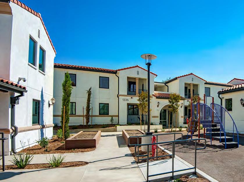
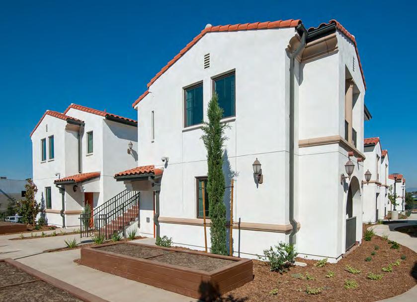
Number of Floors: 2
Gross Floor Area: 32,770 gsf
Fully Occupied: October 2016
Number of Units: 36 - 20 (1BR), 8 (2BR), 8 (3BR) in three separate buildings
Heating / Cooling System: Ducted mini-split heat pump in each unit.
DHW System: For each building, solar thermal system with centralized heat pump water heater.
Project Team
Client: A Community of Friends (ACOF) Los Angeles
Architect: Gonzalez Goodale Architects, Pasadena
MEP Engineer: S Y Lee Associates
Energy Modeling Con-
sultant: Green Dinosaur
Modeled EUI (Site)
21.5 kBtu/sf-year
Modeled Annual Energy Use:
206,300 kWh
Measured EUI (Site) 15.0 kBtu/sf-year
On-Site Renewable Energy System Installed 109 kW
Measured On-Site Renewable Energy Production
197,047 kWh/year
EPILOGUE DESIGNING FOR ZERO CARBON, VOL. 2 121 Case Studies of All-Electric Multifamily Residential Buildings
Project Team
Client:
Affirmed Housing Energy Renovation
Consultant: Redwood Energy, Arcata Energy Modeling Consultant: Redwood Energy, Arcata
Modeled EUI (Site)
28.0 kBtu/sf-year
Modeled Annual Energy
Use:
747,311 kWh
Measured EUI (Site)
Not Available
On-Site Renewable Energy System Installed
358 kW(DC) Solar PV
Measured On-Site Renewable Energy Production
Not Available
Hollywood Palms II, San Diego
Number of Floors: 2
Gross Floor Area: 93,413 gsf
Project Completed: August 2021
Affordable Housing for Low-Income Tenants
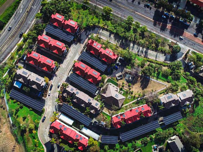
Number of Units: 94 - 44 (2BR), 28 (3BR), 22 (4BR)
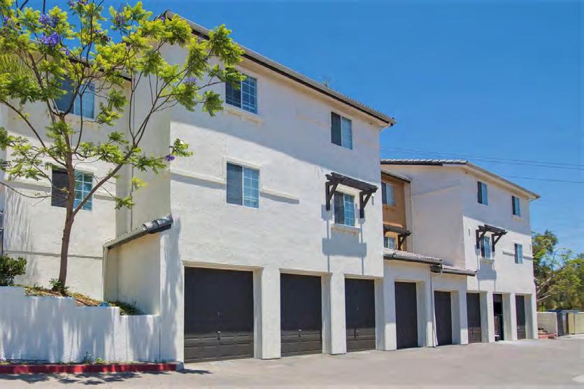
Heating / Cooling System: Split heat pump system with ducted air from the single fan coil in each unit.
DHW System: Electric resistance water heater in each unit
DESIGNING FOR ZERO CARBON, VOL. 2 EPILOGUE 122 Case Studies of All-Electric Multifamily Residential Buildings
Pacific Landing Apartments, Santa Monica Affordable Housing for Low-Income Tenants
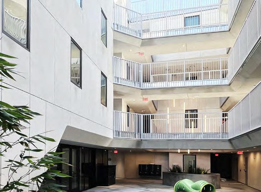
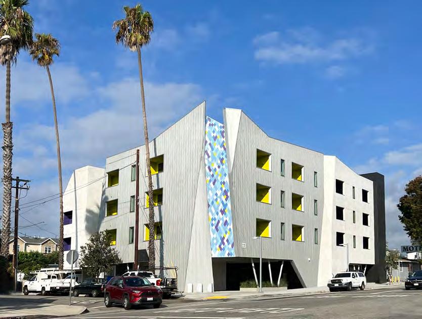
Number of Floors: 4
Gross Floor Area: 42,000 gsf
Fully Occupied: January 2023
Number of Units: 37 - 18 (1BR), 9 (2BR), 10 (3BR)
Heating / Cooling System: Ductless mini-split heat pump system per apartment.
DHW System: Central heat pump system with standard hot water storage and distribution system.
Project Team
Client: Community Corporation of Santa Monica
Architect: Tighe Architecture, Venice
MEP Engineer: IDiaz Design, Los Angeles
Energy Modeling Con-
sultant: Energy Partners, Los Angeles
Modeled EUI (Site)
24.3 kBtu/sf-year
Modeled Annual Energy Use:
203,938 kWh
Measured EUI (Site)
Not yet available
On-Site Renewable Energy System Installed 42.4 kW(DC) Solar PV
Measured On-Site Renewable Energy Production
Not yet available
EPILOGUE DESIGNING FOR ZERO CARBON, VOL. 2 123 Case Studies of All-Electric Multifamily Residential Buildings
Project Team
Client:
G3 Urban (Developer / Contractor)
Architect:
Angeleno Associates, Santa Ana
MEP Engineer: Gouvis Engineering, Irvine
Energy Modeling Con-
sultant:
Gouvis Engineering
Modeled EUI (Site)
9.9 kBtu/sf-year
Modeled Annual Energy
Use:
242,500 kWh
Measured EUI (Site)
Not yet available
On-Site Renewable Energy System Installed
144 kW(DC) Solar PV
Measured On-Site Renewable Energy Production
Not yet available
Walnut Place, Gardena
Number of Floors: 3
Gross Floor Area: 83,246 gsf
Fully Occupied: July 2023
New Market-Rate Townhomes for Sale
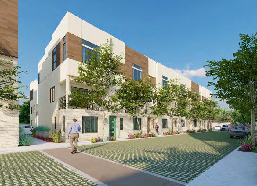
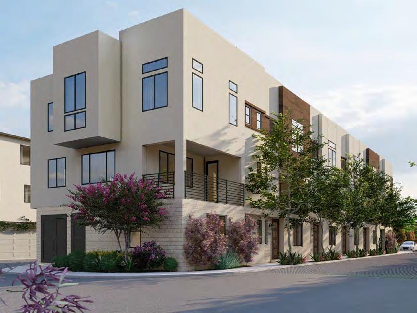
Number of Units: 52 - 7 (1BR), 15 (2BR), 22 (3BR), 5 (4BR), 3 (3BR Live/Work)
Heating / Cooling System: Ducted-air split heat pump system for each unit with separate fan coil units for each thermostatically-controlled zone. Condenser unit located on roof.
DHW System: Individual hybrid heat pump water heater for each unit located within second floor balcony closet or within garage, with standard HW distribution.
DESIGNING FOR ZERO CARBON, VOL. 2 EPILOGUE 124 Case Studies of All-Electric Multifamily Residential Buildings
Edgewood Point, Long Beach New Market-Type Townhomes for Sale
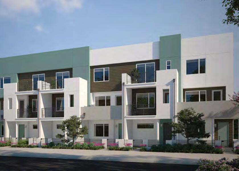
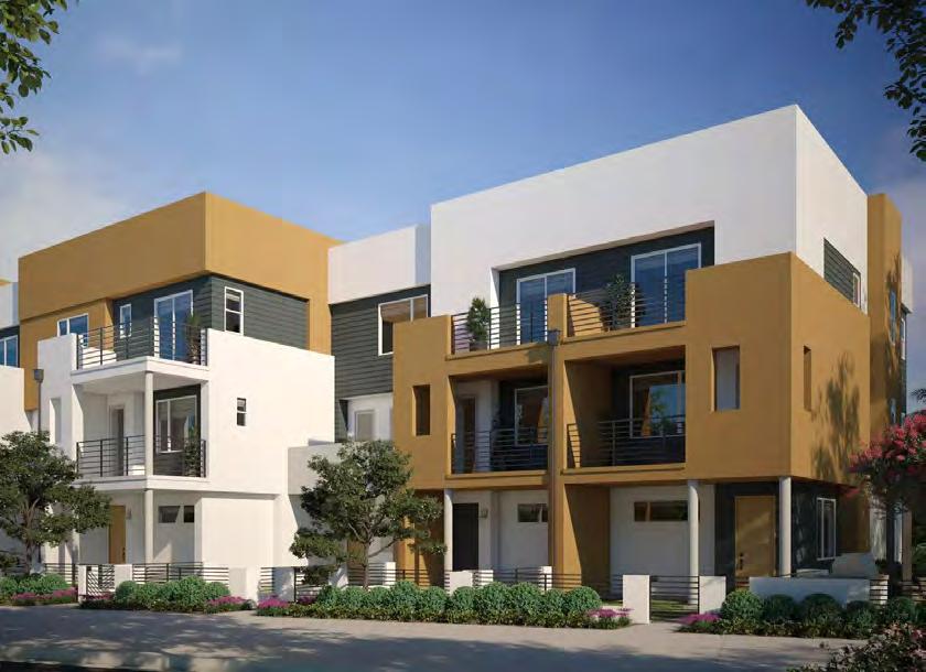
Number of Floors: 3
Gross Floor Area: 54,563 gsf
Fully Occupied: September 2023
Number of Units: 38 2BR Townhomes
Heating / Cooling System: Each townhome: Ducted-air split heat pump system with separate fan coil units for each thermostatically-controlled zone
DHW System: Indivdual heat pump water heater per townhome.
Project Team
Client / Builder: City Ventures
Architect: WHA, Orinda, CA
MEP Engineer: Southwest Group, Irvine, CA
Energy Modeling Consultant: Southwest Group
Modeled EUI (Site) 14.4 kBtu/sf-year
Modeled Annual Energy Use:
230,763 kWh
Measured EUI (Site)
Not yet available
On-Site Renewable Energy System Installed 106.4 kW(DC) Solar PV
Measured On-Site Renewable Energy Production
Not yet available
EPILOGUE DESIGNING FOR ZERO CARBON, VOL. 2 125 Case Studies of All-Electric Multifamily Residential Buildings
Project Team
Client:
MidPen Housing
Architect: David Baker Architects, San Francisco
MEP Engineer: Emerald City Engineers, Lynnwood, WA
Energy Modeling Consultant:
Association for Energy Affordability, Emeryville
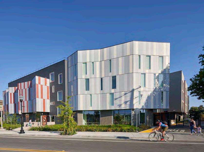
Modeled EUI (Site)
14.7 kBtu/sf-year
Modeled Annual Energy
Use:
365,700 kWh
Measured EUI (Site) 16.7 kBtu/sf-year
On-Site Renewable Energy System Installed 124 kW
Measured On-Site Renewable Energy Production
193,500 kWh
Edwina Benner Plaza, Sunnyvale
Number of Floors: 4
Gross Floor Area (Residential): 87,000 gsf
Fully Occupied: 2019
Affordable Housing for Low-Income Tenants
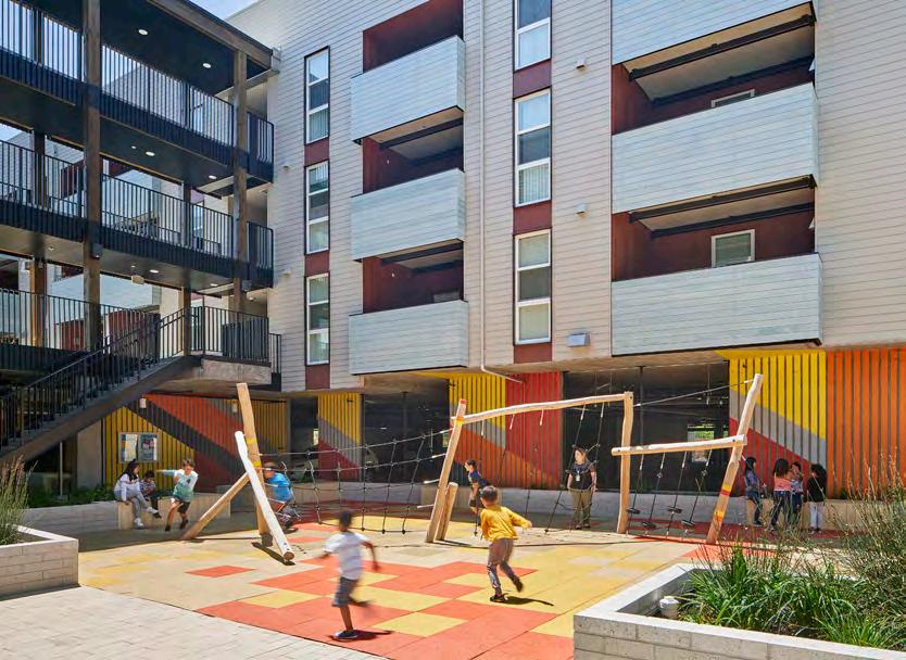
Number of Units: 66 - 30 (1BR), 19 (2BR), 17 (3BR)
Heating / Cooling System: Each unit has a ductless mini-split heat pump
DHW System: Central system with 16 modular Sanden heat pumps and 2,000 gallons of hot water storage with Rheem recirculating heat pump water heater.
DESIGNING FOR ZERO CARBON, VOL. 2 EPILOGUE 126 Case Studies of All-Electric Multifamily Residential Buildings
Quetzal Gardens, San Jose
Number of Floors: 6
Mixed-Use: Affordable Housing above Commercial
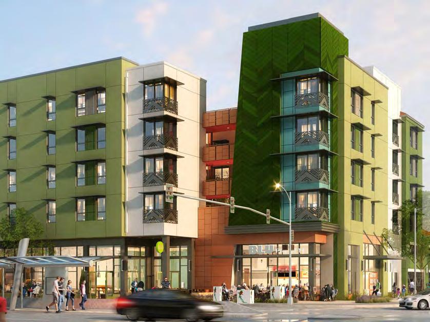
Gross Floor Area (Residential): 57,502 gsf
Fully Occupied: December 2021
Number of Units: 71 - 30 (1BR), 13 (2BR), 28 (3BR)
Heating / Cooling System: Each unit has a split system heat pump with refrigerant flow to one fan coil (two in 3BR units) and air transfer fans between rooms.
DHW System: Each unit has a hybrid heat pump water heater.
Project Team
Client:
Resources for Community Development
Architect:
SGPA Architeture, San Francisco

MP Engineer: Breen Design Group, Torrance
Electrical Engineer: Zeiger Engineers, Oakland
Modeled EUI (Site) 19.8 kBtu/sf-year
Modeled Annual Energy
Use: 333,000 kWh
Measured EUI (Site) 16.2 kBtu/sf-year
On-Site Renewable Energy System Installed Not Available
Measured On-Site Renewable Energy Production
Not Available
EPILOGUE DESIGNING FOR ZERO CARBON, VOL. 2 127 Case Studies of All-Electric Multifamily Residential Buildings
Observations
The Transition Period for Multifamily Housing
As noted in the previous volume of Designing for Zero Carbon, building design has been in a period of transition from an emphasis on zero-net-energy (ZNE) buildings (with a focus on onsite renewable energy systems) to all-electric buildings. The goal to greatly reduce the buildingcaused greenhouse gas emissions that are contributing to climate change remains the same, but the path to this goal has been altered by recent plans to change the energy infrastructure supplying those buildings, namely to change the electricity grid in California to carbon-free production.
Now, projects will be able to operate with zero carbon emissions after 2045 without necessarily achieving ZNE performance, or to be designed with the size of solar PV system usually required for ZNE. Projects reflecting this change of emphasis have only recently been designed, and the case studies in this book (and the previous Volume 1) demonstrate the design issues that now need to be addressed.
So, specifically for the all-electric multifamily housing projects studied in this volume, what issues emerged requiring design strategies to produce buildings with the desired low-carbon emission profile?
Some Things Remain the Same
Even with the programmatic differences and project objectives of the multifamily housing category, there is a continuity of design strategies demonstrated by all five case study projects that effectively supports the emphasis on all-electric design solutions that result in zero carbon emissions when occupied.
•
Energy Efficiency
Energy efficiency for the individual project contributes to an overall energy efficiency for the building sector as a whole, putting less strain on the public utility grid and enabling renewable sources to supply the maximum share of the power required at an earlier date. Energy-efficient design is more cost-effective for the building owner as well.
• Importance of Carbon-Free Renewable Energy
Whether it is sourced from on-site renewable systems at the building site or obtained from the public utility grid, renewable energy supply is clearly beneficial because, once installed, it produces no carbon emissions over the life of the system. For a building owner, the determination of which source is best will be purely a life-cycle cost evaluation.
For the case study projects in this book, which will have 20 years of life before the grid is completely decarbonized, the choice of on-site renewable energy systems was a result of cost-effectiveness calculations as well as indoor air quality and tenant health reasons.
• Building Metering and Performance Verification
Because the transition period to the all-electric building design approach has only recently started, it is essential that the design strategies chosen for these projects be evaluated and their success be confirmed in actual use of the buildings as designed. This can only be done through performance verification after occupancy, typically including actual energy use as metered over one year or more. When building commissioning is
DESIGNING FOR ZERO CARBON, VOL. 2 OBSERVATIONS 128 Case Studies of All-Electric Multifamily Residential Buildings
carried out, usually by a commissioning agent hired by the owner, the performance of all systems can be verified for the post-occupancy period.
Energy efficiency and optimal solar PV system performance will still be high operational priorities in our decarbonized building future, both for individual owners and public utility operators. Systematic metering will help ensure this.
• Affordability, Now More than Ever
For multifamily housing in California, particularly affordable housing for low-income tenants, the issues of construction and operating cost have become critical issues. In response, state and some local governments have taken steps to revise zoning laws to expedite projects and reduce pre-construction costs for developers and non-profit builders. Cost and affordability, as well as marketability (in the case of multifamily units for sale) were key issues in all of the multifamily case studies in this book. In all cases, the all-electric design solutions proved to be the most cost-effective compared to the conventional designs with both gas and electric systems. (See the discussion in Case Study No. 5 – Casa Adelante at 2060 Folsom, p. 108, for a cost analysis of all-electric versus gas-plus-electric design for several multifamily projects.)
What’s New and Evolving
Since the publication of Volume 1 of Designing for Zero Carbon in March 2022, there has been continued development of analytical software tools as well as continued improvement in building technologies and their deployment in multifamily projects.
• An Eye on Embodied Carbon
When the goal of a decarbonized public utility grid in California is realized in approximately 25 years, every all-electric building will operate with zero-carbon emissions—a great eventuality. For building designers, there is also an evolving concern with the importance of embodied carbon, since carbon emissions will still result from the manufacture and transport of construction materials of all types.
There has been a rapidly-developing understanding that this issue can and should be addressed during the design phase of the project. The analytical tools have advanced to the point that they are included in the regular design software and projects can readily be studied for embodied carbon content. Materials specified can be identified as “hot spots” of embodied carbon and replaced, minimizing the project’s overall embodied carbon content. (See the discussion in Case Study No. 5 – Casa Adelante at 2060 Folsom, p.110 and p.111.) Such studies, made feasible only with the recent advances in design software, can make the evaluation of embodied carbon in projects a routine exercise.
• Developing Building Technologies and Energy in Housing
Each of the five case studies in this volume demonstrates creative new approaches to the design of all-electric heating, cooling and domestic hot water systems. While these systems are based on heat pump technology, the solutions are varied appropriately for the size and type of multifamily project. The design solutions can be readily adapted to similar projects.
129 OBSERVATIONS DESIGNING FOR ZERO CARBON, VOL. 2 Case Studies of All-Electric Multifamily Residential Buildings
• Batteries
Although none of the case study projects in this book use batteries for energy storage due to the first cost investment required at the time, for many of the projects, space was designated and infrastructure supplied for future installation. Just as for the rapidlydeveloping electric car industry, battery technology is likely to go down in cost for the building industry application. Combined with the increased incentives for reducing electrical demand during peak hours, namely with significantly-increased rates for energy use during those peak hours, buildings are likely to include battery installation in the near future as it becomes more cost effective.
There is also the incentive to provide resiliency, ensuring power supply during major shutdowns by the public utility for emergency reasons such as wildfires and flooding. Risk avoidance is likely to be a motivator for building owners and developers to invest in battery systems for their projects.
For a variety of reasons, installation of batteries for energy storage will likely be a standard feature of all multifamily building projects in the near future. In fact, as of January 2023, battery storage is required by California Title 24, Part 6, for multifamily projects of four stories or more.
DESIGNING FOR ZERO CARBON, VOL. 2 OBSERVATIONS 130 Case Studies of All-Electric Multifamily Residential Buildings
131 OBSERVATIONS DESIGNING FOR ZERO CARBON, VOL. 2 Case Studies of All-Electric Multifamily Residential Buildings
(Below) October 2021 publication, AIA-CLF Embodied Carbon Toolkit for Architects
Acknowledgments
Many thanks to the following clients and designers of these exemplary projects who gave generously of their time to provide all of the information and insights into various aspects of their design and performance. Special thanks for their patience with the videoconference calls and follow-up emails about design details, their extra work putting together the requested performance data, and their time spent reviewing the final copy for accuracy. Without their openness and supportive cooperation, the case studies would not be the guiding models that they are intended to be.
Client Representatives:
Elaine Camuso, Director of Communications
Viviana Arellano, Project Manager
Wakeland Housing and Development Corporation (For Ivy Senior Apartments [San Diego], Case Study No. 1)
Jordan Gardner, President of Homebuilding
G3 Urban (For Rosecrans Place [Gardena], Case Study No. 2)
Julie Shelton, Asset Manager Self Help Enterprises (For Vera Cruz Village [Richgrove], Case Study No. 3)
Prabhas Kejriwal, CEO
Sageleaf Forest LLC (For Palo Alto Apartments [Palo Alto], Case Study No. 4)
Diana Liao, Property Manager
Chinatown Community Development Center (For Casa Adelante—2060 Folsom [San Francisco], Case Study No. 5)
Design Professionals:
Beena Ramaswami, Associate Principal Steve McDowell, CEO BNIM Architects, San Diego
Salvador Talacon, Project Manager Green MEP Engineering, Newport Beach
Carol Roberts
g.r.e.g. Consulting, Carlsbad
David Ko, Principal Angeleno Associates, Santa Ana
Al Alamad, COO
Larry Cavanaugh, MEP Project Director Gouvis Engineering, Irvine
Erin Feeney, Associate
Katie Ackerley, Principal / Sustainable Design Director David Baker Associates, San Francisco
Meghan Duff, Manager R&D Projects Association for Energy Affordability, Emeryville
132 DESIGNING FOR ZERO CARBON, VOL. 2 ACKNOWLEDGMENTS Case Studies of All-Electric Multifamily Residential Buildings
Kacie McLamb, Principal Integral Group (now Introba), Oakland
Prabhas Kejriwal, CEO Sageleaf Forest LLC, Palo Alto
David Solnick, Architect Palo Alto / New York
Hilary Noll, Associate Principal Mary Telling, Project Architect
Claire McConnell, Associate, Building Performance Analyst Mithun, San Francisco
Stet Sanborn, Vice-President Smith Group, San Francisco
John Andary, Senior Principal Integral Group (now Introba), Oakland
Especially helpful for the exemplary projects described in the Epilogue:
• Sean Armstrong, Redwood Energy (Arcata)
• Casey Castor, Gonzalez Goodale Architects (Pasadena)
• Veronica Hinkley-Reck, SERA Architects (Oakland)
• Patrick Tighe, Tighe Architecture (Venice)
• Tony Segal, City Ventures (Long Beach)
Thanks also to Maya Gantley and Elise Wall, 2050 Partners, prime contractor for this publication, for their suggestions and good advice.
Finally, I would like to thank the team at Southern California Edison (SCE) for supporting and continuing this series of publications on all-electric (zero-carbon-ready) buildings, particularly Dave Intner, AIA.
--Edward Dean, FAIA, Bernheim + Dean, Inc.
133 ACKNOWLEDGMENTS DESIGNING FOR ZERO CARBON, VOL. 2 Case Studies of All-Electric Multifamily Residential Buildings
134 Case Studies of All-Electric Multifamily Residential Buildings
 This publication is funded by California utility customers and administered by SCE under the auspices of the California Public Utilities Commission.
