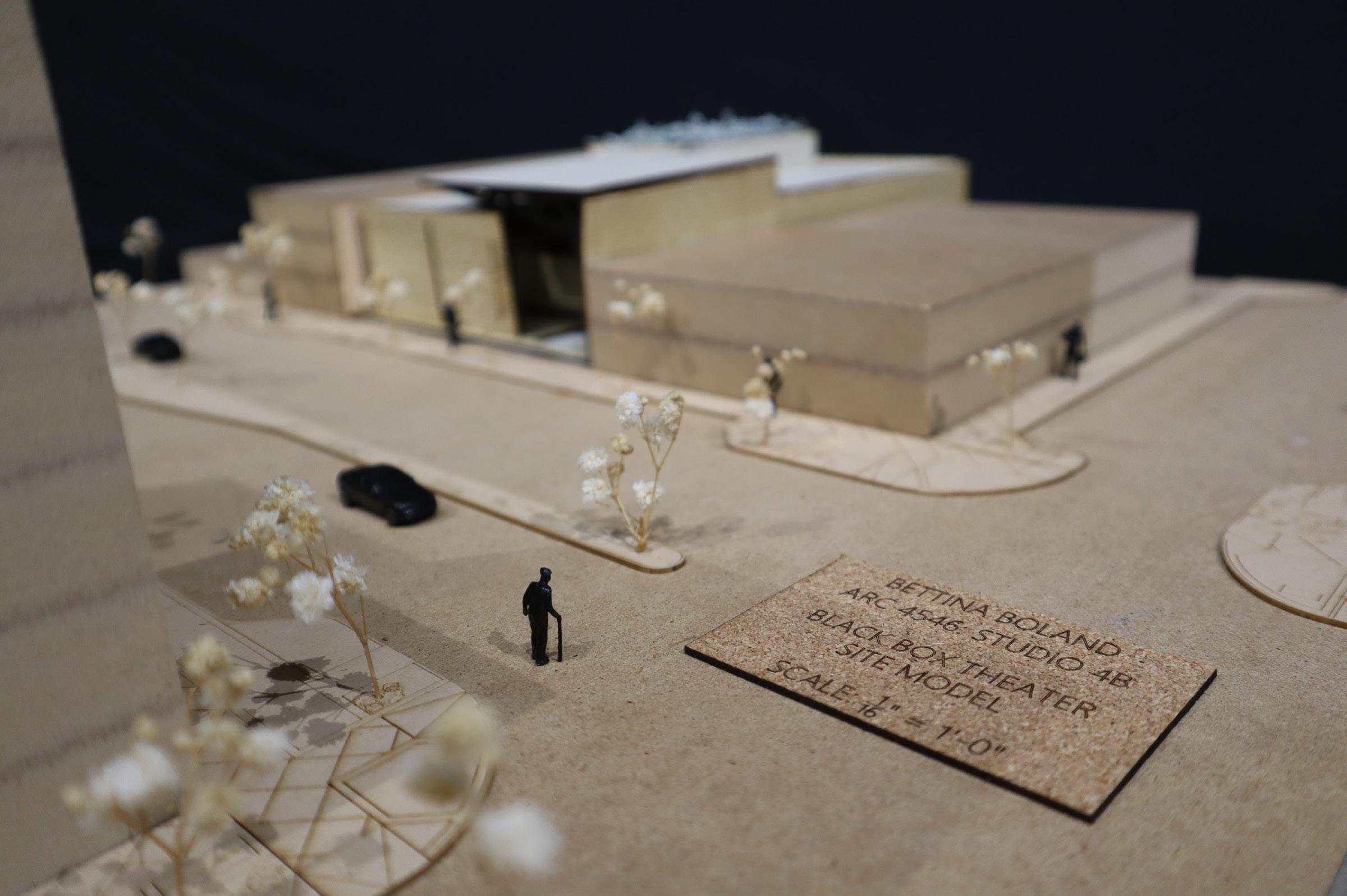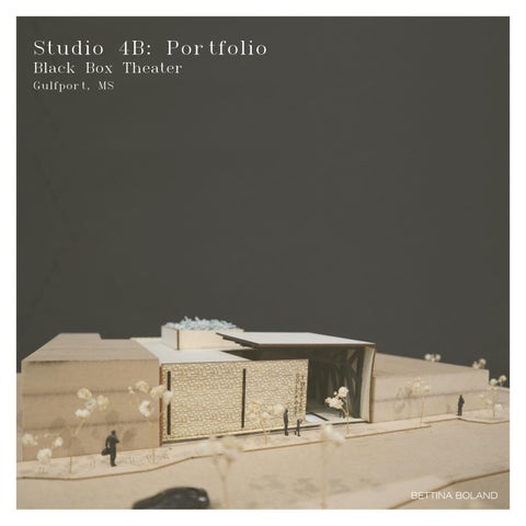

Studio 4B: Portfolio
Black Box Theater
Gulfport, MS

BETTINA BOLAND
CONCEPTUAL DESIGN
FACADE
SUSTAINABILITY + EE
TECTONICS + ASSEMBLY
GULFPORT SITE ANALYSIS 01 05 04 03 02 07 06 08
ENVIRONMENTAL SYSTEMS
CODES + ACCESSIBILITY
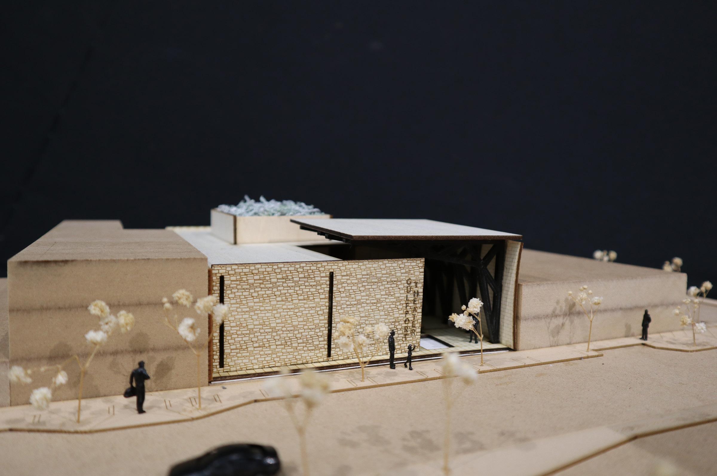
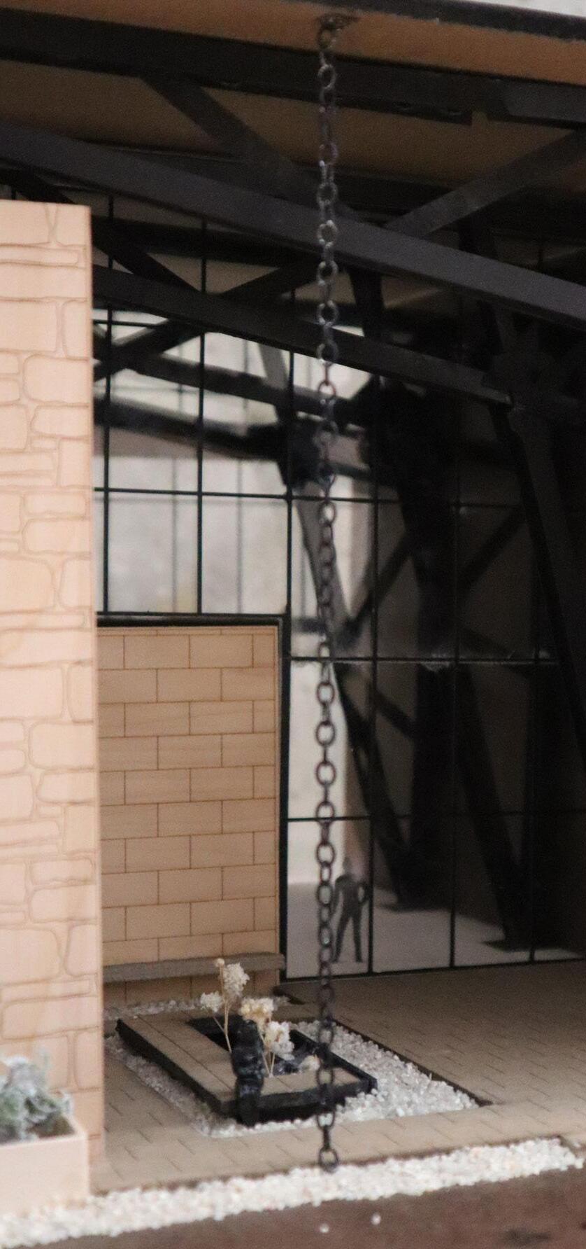
MODEL PHOTOS
Page
Page
Page
Page
Page
Page 16-17 Page
Page
Page
4-6
7-9
10-11W
12-13
18-23 FLOORPLANS
24-25
26-27
28-31 09
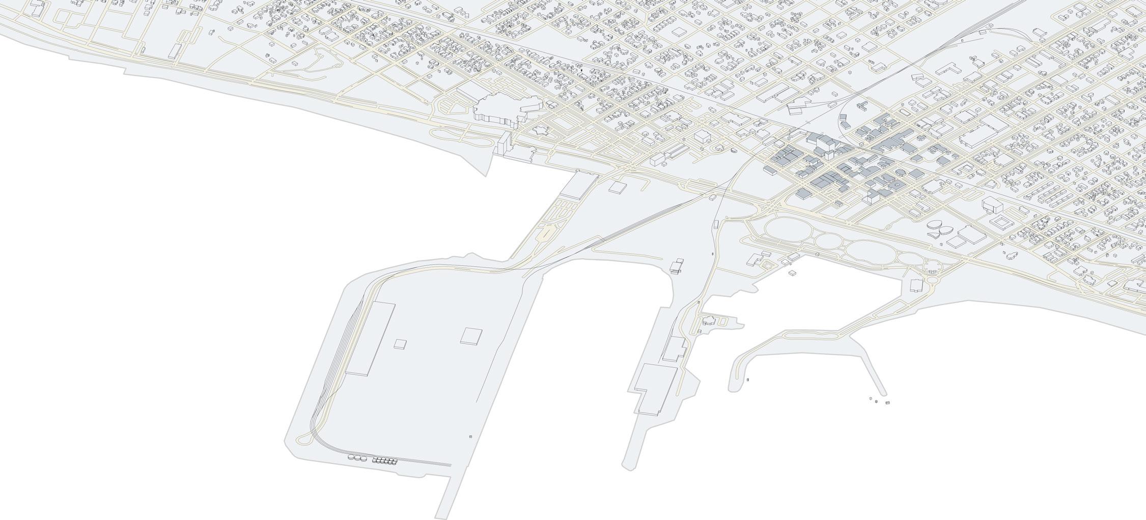
This site analysis draws inspiration from Kevin Lynch’s work, ‘The Image of the City,’ which emphasizes the importance of understanding the perceptual qualities of urban environments. Lynch identifies key elements—nodes, paths, edges, districts, and landmarks—that shape people’s mental maps and experiences of a city. Applying Lynch’s framework to this analysis, I identify public nodes, such as parks and commercial areas, as vital social and cultural hubs. Urban paths, including sidewalks and roads, form the arteries that connect these nodes and facilitate movement throughout the city. Meanwhile, edges delineate boundaries and transitions between different urban realms, influencing perceptions of safety and comfort.
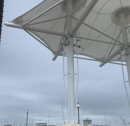
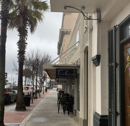
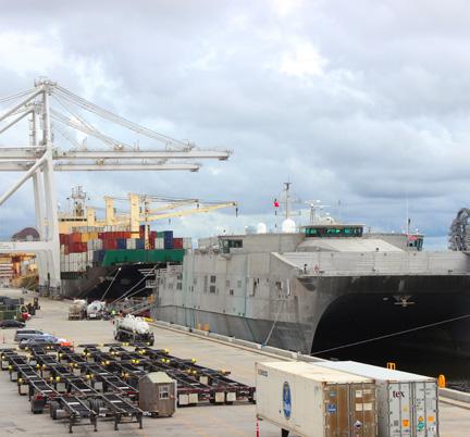
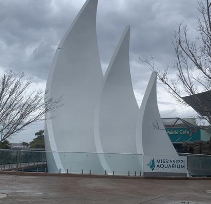
Jones Park Canopy 25th Ave Sidewalk Port of Gulfport Mississippi Aquarium 1 4 2 3
GULFPORT SITE ANALYSIS 04 1 4 2 3


Parking
Public Nodes
Fishbone Ally
Park
Rail Roads
Noise Disturbance
Primary Road
Secondary Road
Pedestrian Path
Bus Routes


05
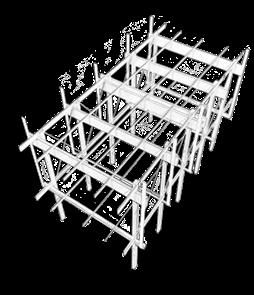
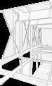
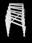
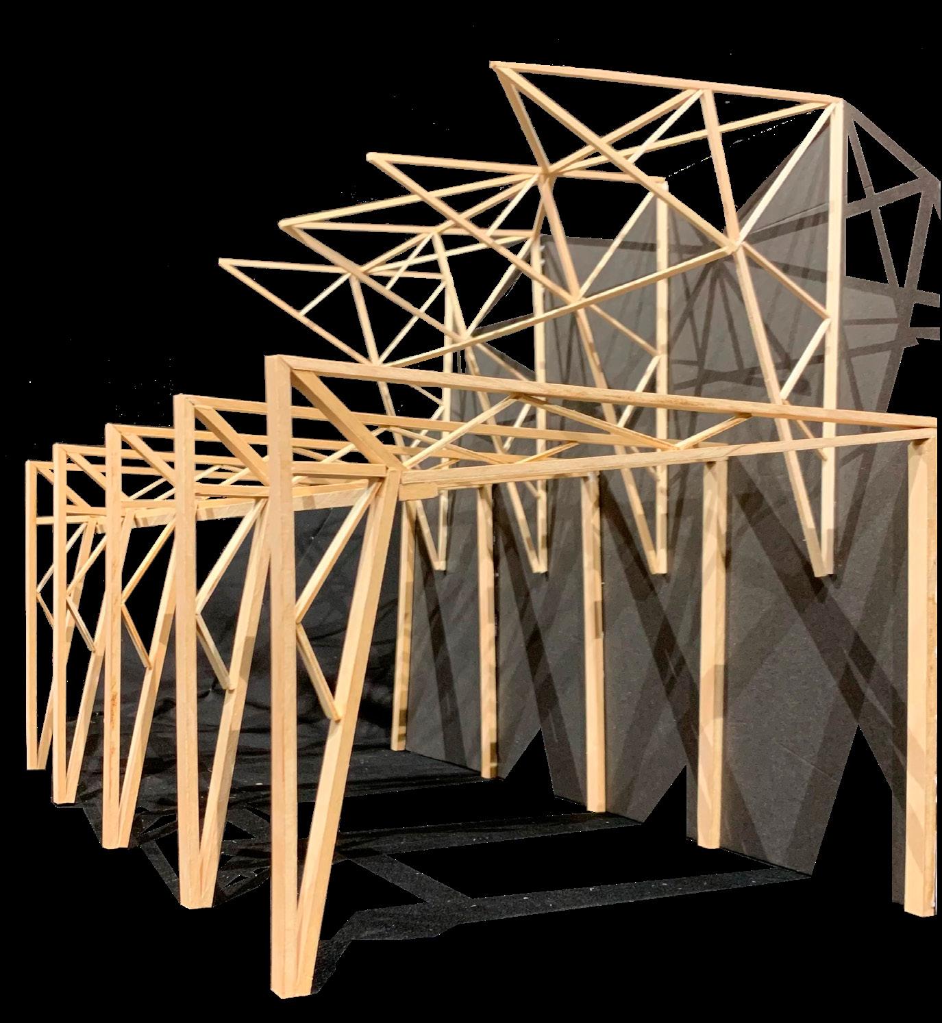
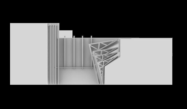
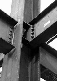
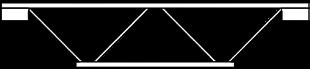
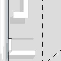
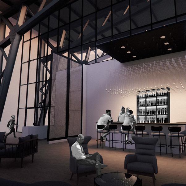
From the inception of my truss concept design, my goal was to create an immersive experience for visitors, blending the robustness of steel columns with the inherent beauty they offer when exposed. An exploration of precedents in both theaters and truss structures revealed a lack of examples where these two elements harmonized. Recognizing the potential in the visual appeal of exposed steel, I delved into numerous concept mass models to arrive at the final design presented here.
The focal point of this truss design is its dual role as both a structural and visually captivating system. Contrary to conventional notions that prioritize the performance space, I sought to elevate the importance of the "Front-of-the-House," including the lobby. By employing the distinctive form of a scissor truss and incorporating the intricate tectonics that bind this expansive structure together, I aimed to transform the truss into both a wall and a roof.
BLACK BOX THEATRE INFILL SITE 06
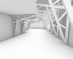
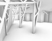
TECTONIC GESTURE MODELS


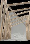


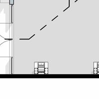
Moving to the second floor, the truss system is again oriented horizontally, but with distinct features for a fresh visitor experience. Notably, only one wall is supported by the truss structure, adjacent to the floor below. The upper section introduces an upward angle, allowing for the potential incorporation of skylights or additional natural light. This design choice not only facilitates the illusion of higher ceilings, countering the typical reduction in ceiling height with each successive story but also adds a layer of spatial dynamism to the overall theatre design.
The first level features scissor trusses positioned horizontally, complemented by towering steel beams on the adjacent side. This design creates an expansive, open floor plan, inviting various interior design installations. Beyond its structural functionality, the design also offers a unique experience for visitors entering a space dominated by these imposing yet seemingly weightless steel structures.
Despite its steel truss framework, the design defies expectations associated with industrial warehouses, challenging the conventional perception of a theatre.
In essence, the Dynamic Truss Theatre is a testament to the transformative potential of architectural innovation, challenging preconceptions and reshaping the traditional boundaries of theatrical spaces.
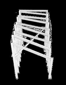
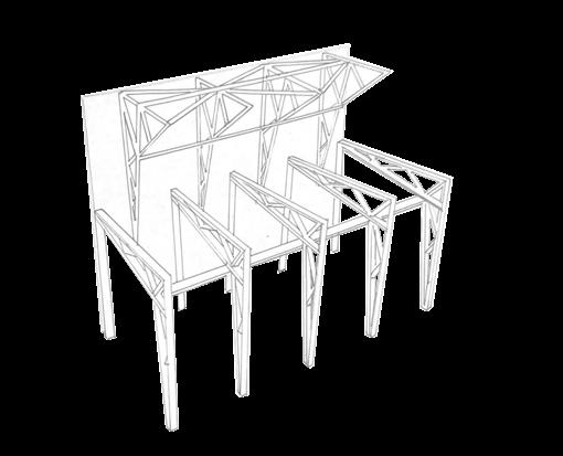
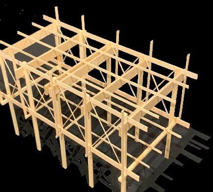
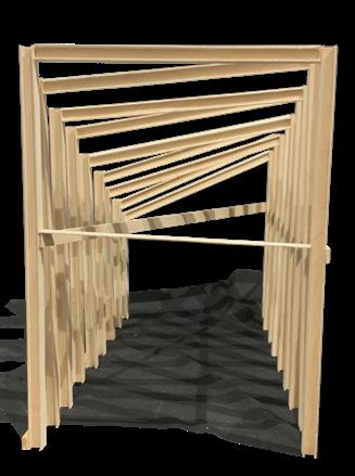
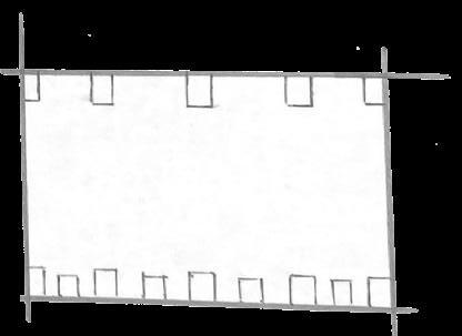
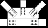
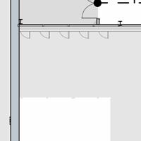
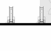
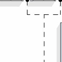
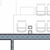
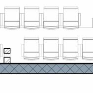
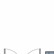
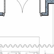
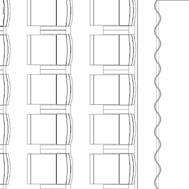
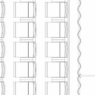
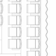
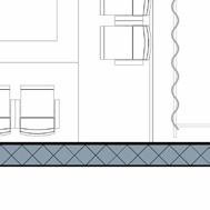
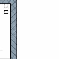
Post & Beam System In the pursuit of crafting a captivating experience for visitors to the Gulfport black box theatre, my design journey transitions to the enchanting simplicity of Post and Beam System. The inherent charm of this concept lies in its unassuming complexity, a manifestation of 18 substantial steel columns varying in size meticulously paired to form an H-shaped structure. The ingenious play with sizes results in deliberately lopsided configuration, standing as testament to structural ingenuity while offering truly unique interior experience. The arrangement of these columns unfolds as an artful dance, with the left side gracefully stepping down to half the height of its right-sided counterparts. This intentional asymmetry serves a dual purpose not only sculpts an interior that seemingly curves downward on one side, creating dynamic spatial quality but also contributes to a distinctive facade. The box in plan transforms into an architectural marvel where the left side reaches its zenith and converges sharply with the right at defined angle. The deliberate asymmetry and the play of perspectives within this Post and Beam System transcend the conventional space, they are greeted with an immersive environment, where the structural elements become more than supports they are sculptors of an experience. The lopsided elegance challenges preconceived notions of symmetry, inviting patrons to engage with the spatial narrative in a manner that both visually intriguing and spatially dynamic. In essence, the Asymmetric Elegance in Post and Beam Theatre redefines the notion of simplicity, transforming structural elements into visual symphony that captivates and invites exploration within the confines of its carefully orchestrated asymmetry. To the right, you will find some diagrams highlighting key design significant in this Post and Beam System. Included are plans and elevations intended to visualize spatial qualities. Pictured to the right is a vignette capturing the pronounced impact of the large structural members on those visiting the theatre. model plan w/ post hight (inches) interior roof feature second level balcony in plan roof elevation street elevation Composite System Inspired by the innovative spirit of the Writers Theatre by Studio Gang, my final design introduces a compelling Composite System, seamlessly blending the robust Post and Beam framework with the flexibility of Post Tension Wires. This amalgamation is not just an architectural fusion but conceptual evolution aimed at offering a multi-faceted experience within the Gulfport black box theatre. The Post and Beam elements form the backbone of this design, a sturdy yet elegant framework comprising expansive beams that stretch across the entirety of the space, eschewing double stories for fluid, interconnected layout. This intentional choice not only opens up the potential for diverse programmatic possibilities but also allows for an unobstructed flow, promoting an inclusive and adaptable interior environment. Building upon the legacy of Studio Gang’s Writers Theatre, the incorporation of Post Tension Wires introduces dynamic layer to the composite system. This addition not only enhances structural integrity but also facilitates the creation of outdoor walking spaces. The intertwining of these wires not only supports the structure but also serves as an opportunity for potential screening systems, transforming the theatre into a versatile canvas for artistic expression. In essence, the Composite System marries structural robustness with spatial flexibility, embodying dynamic fusion that transcends the conventional black box theatre. is testament to the potential of architectural innovation, inviting patrons to explore space that not merely venue but an immersive and ever-evolving experience. The outdoor spaces foster a connection between the interior and the surrounding environment, creating an inviting atmosphere for patrons to engage with the arts beyond the confines of traditional theatre walls. The design encapsulates the spirit of adaptability, catering to a myriad of functions, from traditional performances to experimental installations, providing a canvas for creativity and fostering sense of community engagement. cross-bracing located on the overhangs allowing for future design Bettina Boland material dimensions 1
2:
Large Truss Small Truss
: Large Truss
Small Truss
07
SPATIAL PROGRAMMING DIAGRAMS
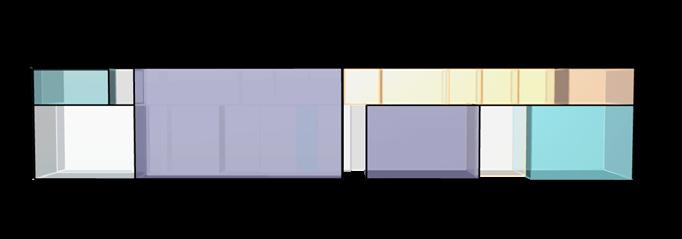
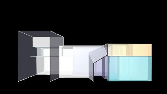

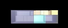
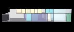
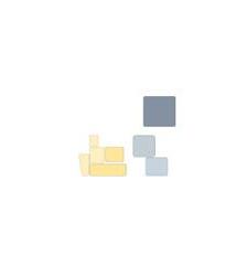

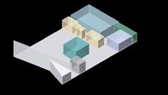

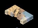

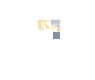
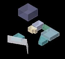

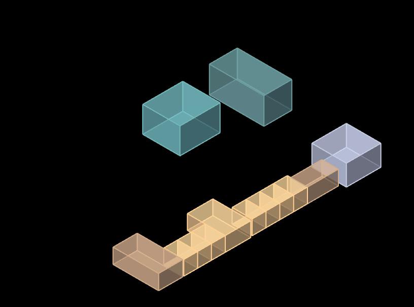
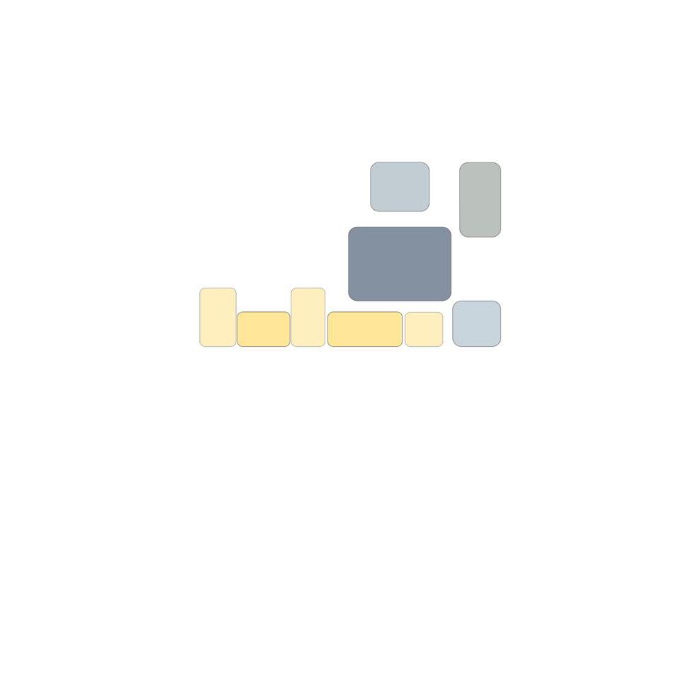
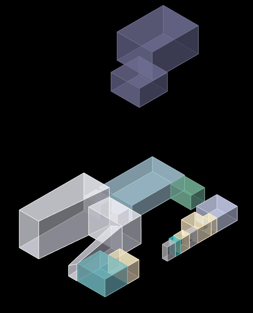
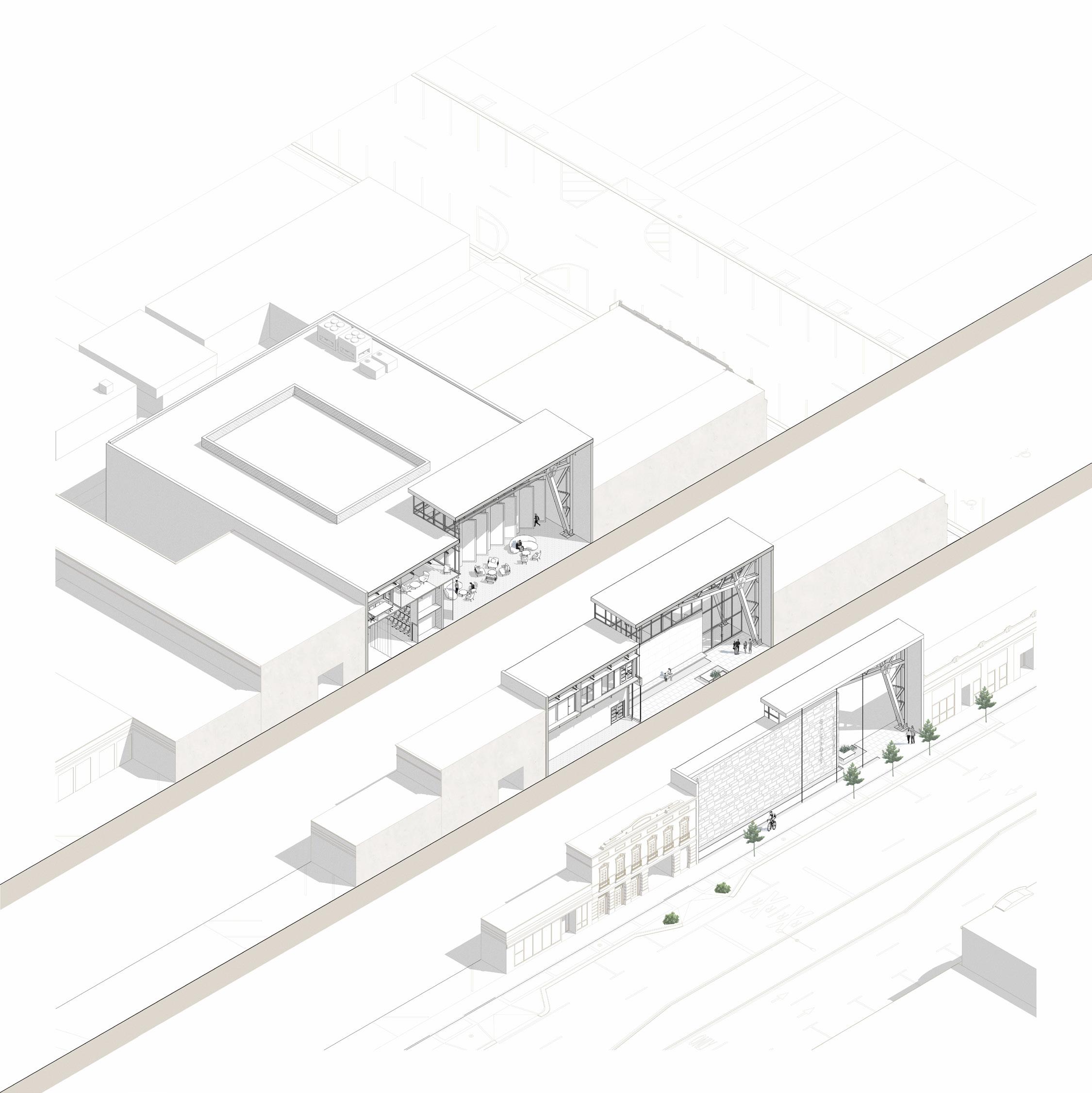
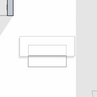
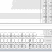
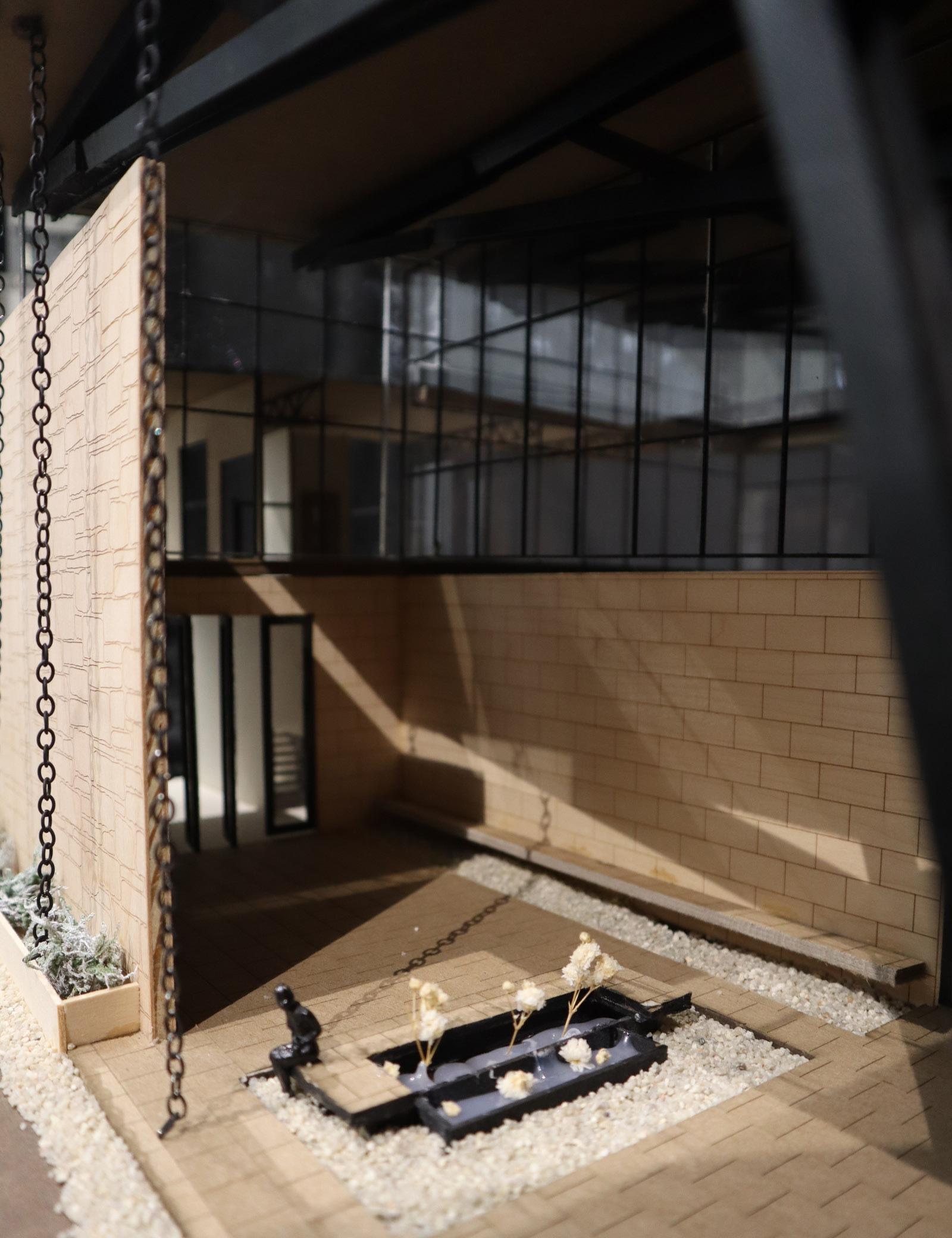
In this gesture model, the design centers around an exterior courtyard feature, creating a focal point for the building and a vibrant node for the public. The courtyard serves as a gathering space, activating the street during the day and fostering community engagement. A large lobby wraps around the courtyard, providing a welcoming entrance space that connects to the outdoor environment. Notably, the rehearsal studio is positioned at the front facade, allowing it to be visible and accessible to the public, emphasizing transparency and engagement. Both the large and small theaters are located on the first floor for convenient access for performance attendees. To facilitate ease of operations, the scene shop is strategically placed on the same level as the theaters, promoting efficient set construction and storage. Additionally, the layout separates public and private spaces, with offices and conference rooms situated on the second level. An exploded axon of the two levels illustrates the spatial relationships, emphasizing the proximity of the theaters and the overall circulation flow within the building.

LOBBY REHEARSAL THEATRELARGE DRESSING ROOM SHOPSCENE STORAGE LOADING THEATRESMALL DRESSING LEVEL ONE COURTYARD CONFERENCE THEATRELARGE OFFICES STORAGE COSTUME SHOP OFFICES SMALL CONFERENCE LOBBYOFFICE MECHANICAL LEVEL TWO LEVEL TWO LOBBY THEATRELARGE LOADING DRESSINGSHOPSCENE STORAGE SMALLTHEATRE REHEARSAL MECHANICELECTRIC/ OFFICES STORAGE STORAGE OFFICES LARGE CONFERENCE CONF.SMALL LOBBYOFFICE REHEARSAL LARGE SMALL OFFICES CONFERENCE In the second gesture model, the focus is on the interaction between the lobby space and the two theaters, as well as the rehearsal room positioned between them. This layout allows for flexibility in production space utilization and provides welcoming reception area for community events. The lobby designed to be open and inviting, serving as comfortable waiting space and featuring interesting steel structure integration. Offices and conference rooms are situated on the second level, effect created by the conference room and theater spaces, adding visual interest to the design. Additionally, small outdoor space in front of the facade enhances the street scape, creating plaza and elevated elevation. As in the first model, the scene shop is strategically located on the first level, facilitating efficient set construction and storage. CONFERENCE SMALL OFFICES plan study longitudinal section SPATIAL #2 LOBBY REHEARSAL THEATRELARGEDRESSING STORAGELOADING COURTYARD DRESSINGROOM SHOPSCENE UPSTAIRSLOBBY SCENESHOP THEATRESMALL CONF.LARGE CONF.SMALL OFFICES STORAGE OFFICES DRESSING ROOM LEVEL TWO COSTUME STORAGE COSTUME SHOP ROOM REHEARSAL LARGE THEATRE In the third gesture model, the focus shifts to an elevation study, exploring the concept of theaters protruding from the roof and incorporating exposed structural elements. To achieve this effect, the small theater positioned on the second floor, allowing for the creation of a dynamic roof line. This layout also provides opportunities to re-imagine the rehearsal space, costume shop, and lobby experience. Additionally, the abundance of space on the first floor allows for the creation of courtyard in ‘v’ shape, enhancing the building’s facade and creating a welcoming entrance. The angles of the costume shop and rehearsal space mirror those of the courtyard, promoting visual cohesion. Offices are strategically placed toward the back of the building on the second floor, offering privacy and access to natural light. The inclusion of an outdoor rooftop area for employee use further maximizes the available space and enhances the building’s functionality. Different from the previous models, the scene shop spans both the first and second levels, accommodating the elevated small theater and facilitating efficient set construction. elevation study LOBBY SCENE SMALL THEATRE COSTUME Bettina Boland longitudinal section SPATIAL #3 CONFERENCE ROOM REHEARSAL LOBBY LARGE THEATRE SMALL THEATRE REHEARSAL OFFICES CONFERENCE ROOM BACK OF HOUSE transverse section longitudinal section
08
STRUCTURE GESTURE STUDIES


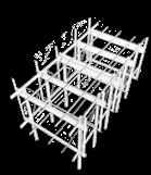
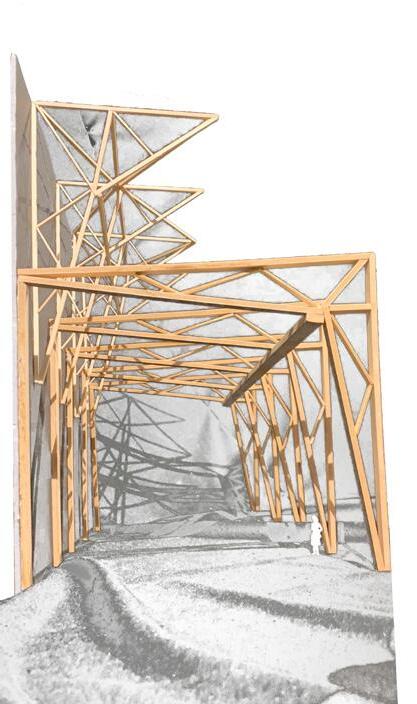
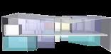
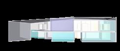
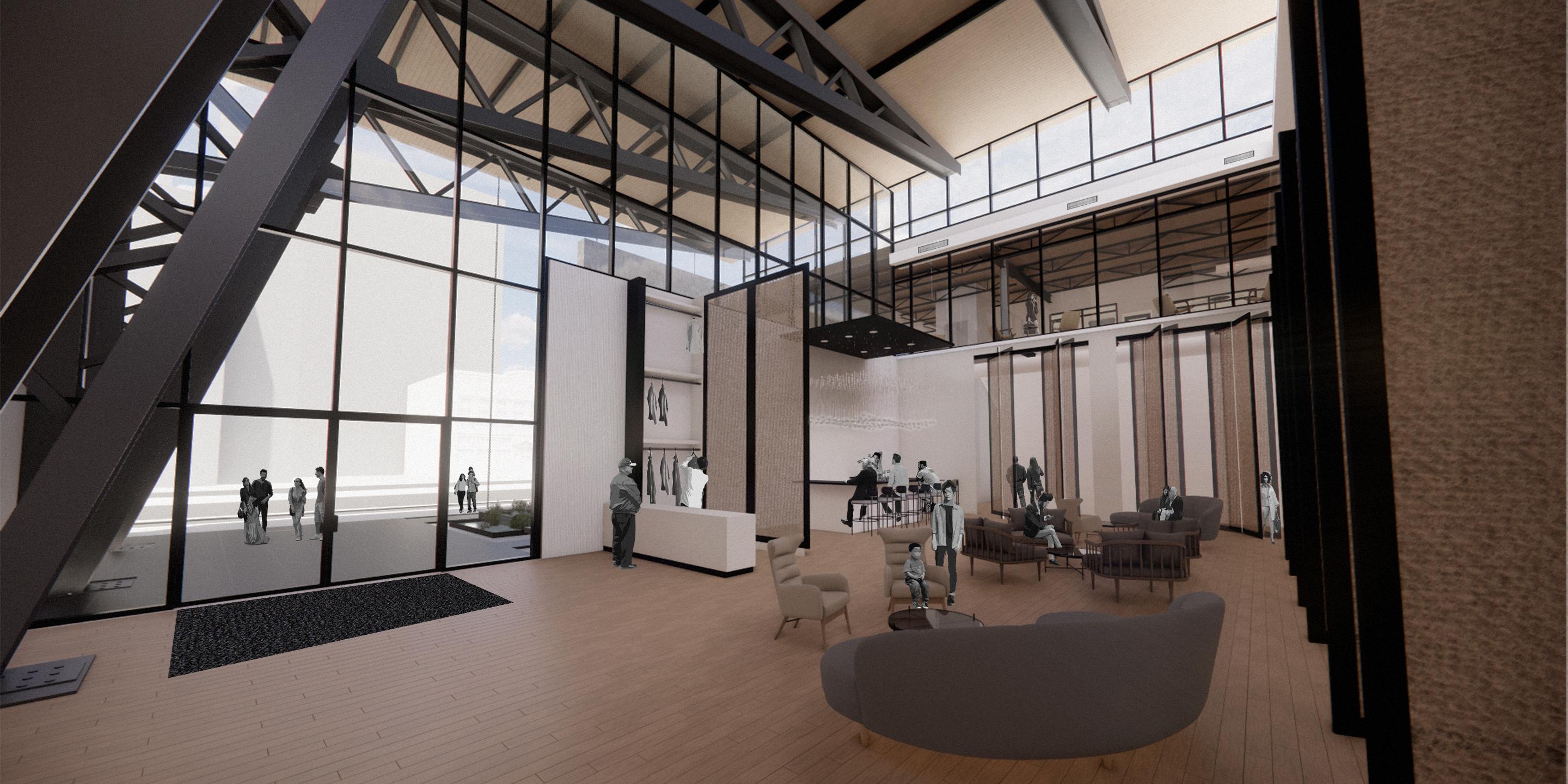
This structure gesture builds upon the speculative model’s central courtyard concept, emphasizing transparency and engagement with the public. Structural elements interact with the courtyard, defining the space while maintaining openness. It employs scissor trusses as the primary structural element, dynamically scaled to accommodate various spatial requirements. The scissor trusses are strategically exposed as architectural features, highlighting their beauty and strength. In the lobby area, a large scissor truss runs along one side, creating a defining architectural element that enhances the spatial experience while maintaining openness and connectivity. This integration of structure and design aligns with the programming gesture’s emphasis on creating welcoming and visually engaging spaces for public interaction.
REHEARSAL
SMALL THEATRE
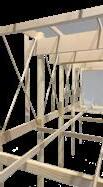
POST & BEAM INTEGRATION lobby space to the right of the building, with the large theatre to the left, the facade to the right, and balcony above. The integration of a scissor truss as vertical element not only creates interesting supports, but also the structure. This gesture model includes design features from my previous Truss System study. In exploring the idea of a singular module, scaled up and down as needed, found this system to be very versatile in use. While materiality not yet applied, the idea of exposing the structure with only glass facade placed front, can be an appealing feature and intriguing to the public. This structure gesture builds upon the programming gesture’s emphasis on creating flexible and welcoming spaces for community interaction. utilizes scissor trusses as the primary structural element, strategically positioned to enhance the interior space. Unlike the first model where scissor trusses were used to create a defining architectural feature, in this gesture, they run perpendicular to the facade, creating a dynamic and visually striking interior space. This unique configuration adds a sense of depth and texture to the lobby, enhancing its aesthetic appeal and spatial experience. In this facade study, hope to create a clean look with all structure sitting inside the building, opposite the other gesture models. The shorter wall to the right of the facade is intended to help the theatre better fit with the existing context. Taking the hight of the building to the right and beginning there, but angling up as needed for theatre. SECOND LEVEL STRUCTURE SMALL THEATRE LARGE THEATRE REHEARSAL GESTURE #2 Pictured above is a shot of the lobby space to the right of the building, with the large theatre to the left, the facade to the right, and balcony above. The integration of a scissor truss as vertical element not only creates interesting supports, but also the structure. This gesture model includes design features from my previous Truss System study. In exploring the idea of a singular module, scaled up and down as needed, found this system to be very versatile in use. While materiality not yet applied, the idea of exposing the structure with only glass facade placed front, can be an appealing feature and intriguing to the public. In this facade study, hope to create a clean look with all structure sitting inside the building, opposite the other gesture models. The shorter wall to the right of the facade is intended to help the theatre better fit with the existing context. Taking the hight of the building to the right and beginning there, but angling up as needed for theatre. SECOND LEVEL STRUCTURE Bettina Boland GESTURE #2
LARGE THEATRE
09
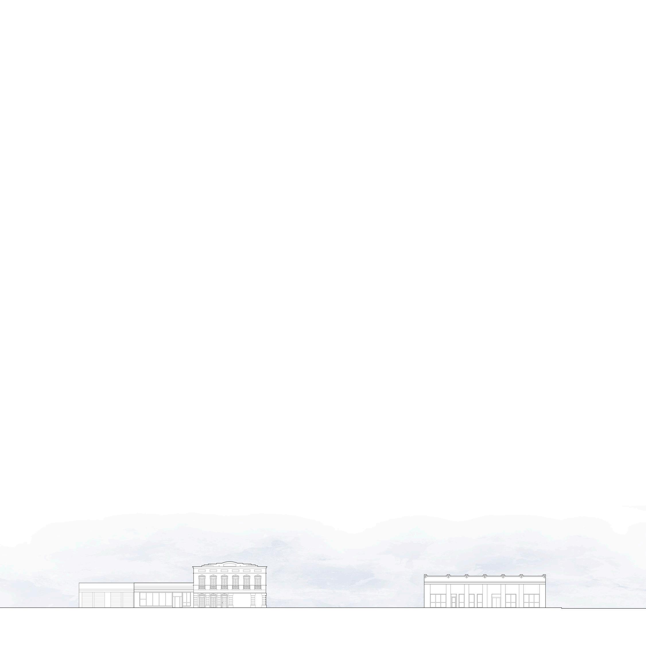
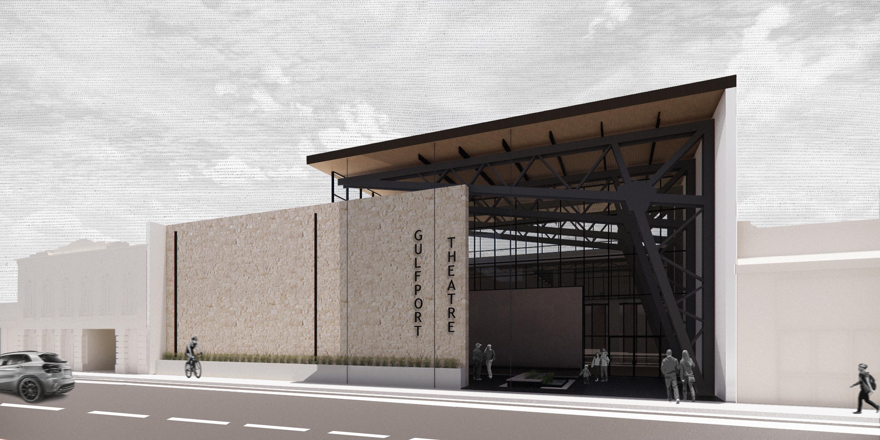
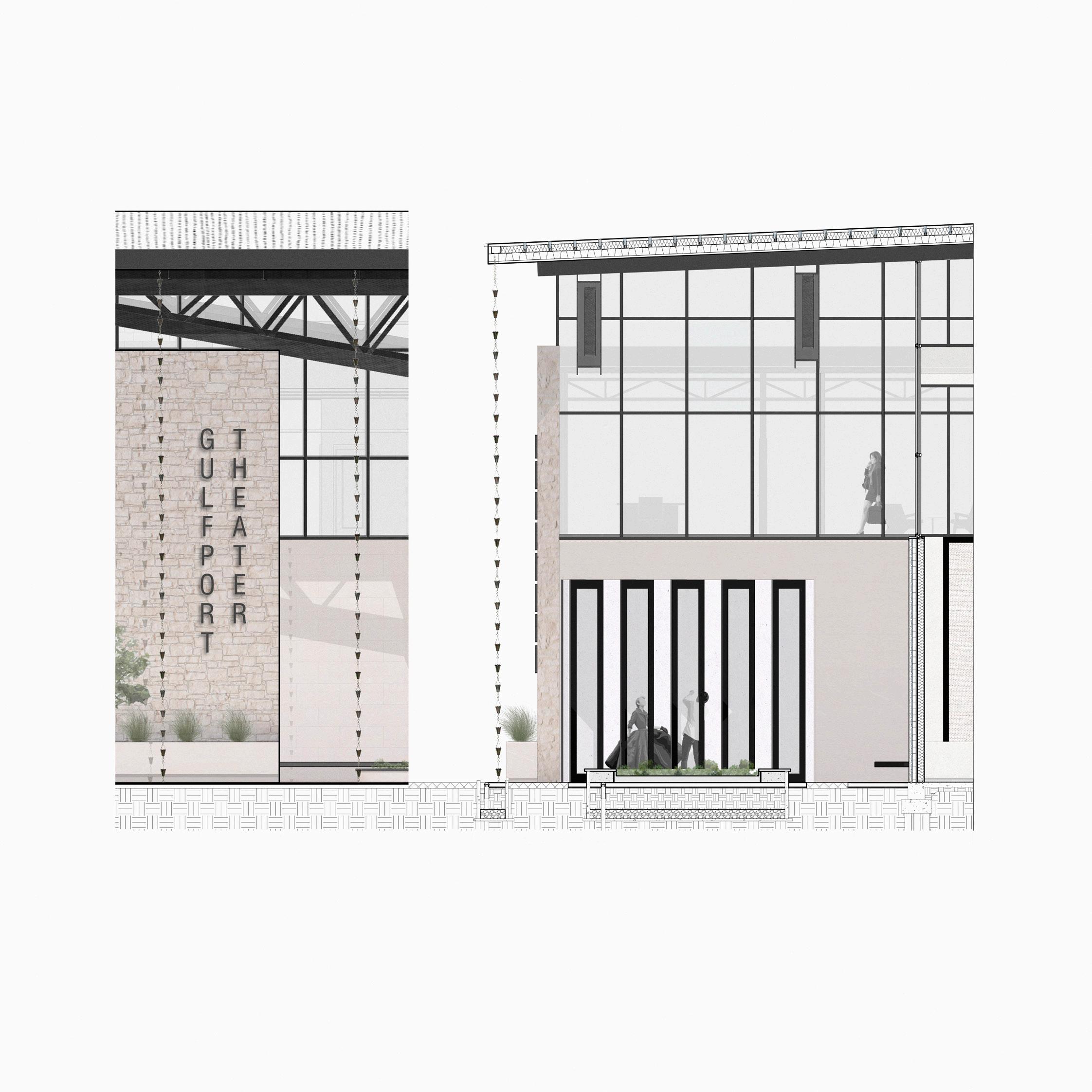
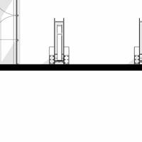
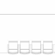
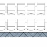
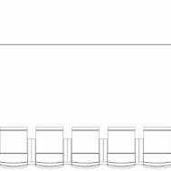
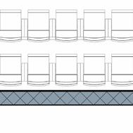
FINAL DESIGN: WEST ELEVATION

10
WEST ELEVATION
11
SCALE: 3/16" = 1'0"
MATERIALS + EMBODIED ENERGY
9 1 2 3 6 7 8 5 4 10 11
12
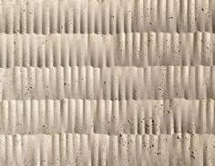
1. Smoothface Limestone Veneer (Tracery Stone Co.):
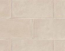
Sourced from Tracery Stone Co. in Birmingham, AL, this stone will feature a smooth finish with minimal color variation, enhancing the secondary façade wall at the entrance with a clean and contemporary aesthetic. Exclusively used on the exterior wall, it adds sophistication and visual appeal to the architectural composition.
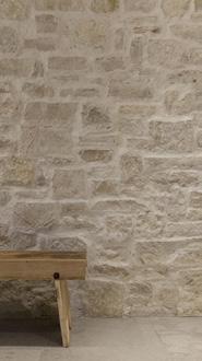
2. Splitface Limestone Veneer (Tracery Stone Co.): This customizable veneer system, sourced from Tracery Stone Co. in Birmingham, AL, adds rustic charm and authenticity to both the front and back sides of the primary wall. This project will include the 4LV Aged Splitface Beignet Limestone Veneer with Mortar Smear by Tracery Co. so its aged appearance and mortar smear detail enhance the architectural character, providing a timeless aesthetic to the design.
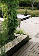
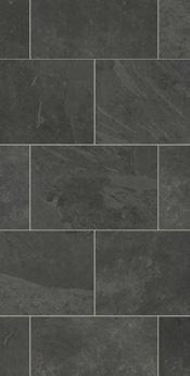
3. Black Porcelain Pavers (Landmark Ceramics): These 24"x48" tiles, each .35" thick, offer a sleek and contemporary aesthetic for the exterior courtyard, providing durability and sophistication with their bold black color and large format dimensions. The color Essence Montauk Black paver will be used for the front courtyard.
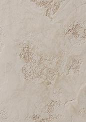
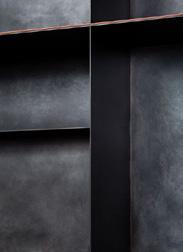
4. Limewash Stucco: A traditional yet versatile finish for the firewall, limewash stucco offers a timeless aesthetic with its soft, textured appearance and subtle variations in color. Applied with a breathable, eco-friendly formula, it provides both durability and a sense of heritage to the architectural design.
5. Curtain Wall Glazing System (Oldcastle Building Envelope Company): Curtain wall glazing is used in the large atrium found in the lobby. The glazing used will be sourced from Oldcastle Building Envelope Co., Specifically the FG-5750 StormMax storefront, which provides significant hurricane protection through the use of insulating laminated glazing.
6. Corten Steel with Weather Protectant Coating: Steel in a dominant material located on the exterior and interior of the building as a structural and architectural feature. The custom design of the steel will be used for 4 large trusses. Due to the coastal location, with the salty air and heavy winds, it is necessary to coat the steel with a weather protectant coating.


Total weight of material: 557,523 lbs
Total EE: 2,387,375 MJ
Distance Traveled: 1,816 Miles
Total Transportation EE: 3,144MJ
EMBODIED ENERGY: 2,390,520 MJ
This is equivalent to a 40W Light Bulb operating for 16,600,853 hrs.
10. Thin Sheet Metal for Accent Materials 7. Gray Slate Pebbles 9. Standing Seam Metal Roof 8. Green Roof SystemBELOW ARE THE EMBODIED ENERGY CALCULATIONS FOR THE PROVIDED MATERIAL INFORMATION: Name of Material: Material Description: Weight units Unit weight 4.51 lbs Amount of material 1,322.00 Total weight of material (lbs) 5,962.22 lbs Total weight of material (Kg) 2,704.42 Kg Cradle to Gate Embodied Energy (EE) (use ICE spreadsheet) units EE unit value for material 12.00 MJ/Kg Total EE (EE x weight (Kg)) 32,452.98 MJ Transportation Embodied Energy (EE) Material Manufacturer Name Material Manufacturer Location Project Location Distance from manufacturer to project site units Long Haul Aircraft miles 15 Ton Truck 465.00 miles 35 Ton Truck miles Costal Shipping miles Rail miles Ocean Shipping miles Total 465.00 miles Transportation EE per type of transport units Long Haul Aircraft (9.49 MJ/ton-mile) 0.00 MJ 15 Ton Truck (2.19 MJ/ton-mile) 1,018.35 MJ 35 Ton Truck (1.37 MJ/ton-mile) 0.00 MJ Costal Shipping (0.39 MJ/ton-mile) 0.00 MJ Rail (0.37 MJ/ton-mile) 0.00 MJ Ocean Shipping (0.23 MJ/ton-mile) 0.00 MJ Total Transportation EE 1,018.35 MJ Total Embodied Energy (EE) 33,471.33 MJ Grand Total Embodied Relatable context the 40 watt lightbulb EE kilowatt hour equivalent units kWh equals 3.60 MJ Total kWh (total EE 3.6 MJ) 9,297.59 kWh Powering the 40 watt light bulb units 1 kWh powers a bulb for 25.00 hrs Total Operating Hours 232,439.82 hrs Grand Total Operating Black Porcelain Pavers Landmark Ceramics UST,Inc. 1427 N. Main Street 1412 & 1410 25th Ave, Gulfport, MS The ESSENCE MONTAUK BLACK tiles by Landmark Ceramics will be used an the main architectural pavers in the exterior couryard. These will be 24"x48" tiles, each .35" thick Name of Material: Name of Material: Name of Material: Material Description: Material Description: Material Description: Weight units Weight units Weight units Unit weight 211.00 lbs Unit weight 76.00 lbs Unit weight 12.00 lbs Amount of material 748.00 Amount of material 80.00 Amount of material 316.00 Total weight of material (lbs) 157,828.00 lbs Total weight of material (lbs) 6,080.00 lbs Total weight of material (lbs) 3,792.00 lbs Total weight of material (Kg) 71,589.52 Kg Total weight of material (Kg) 2,757.84 Kg Total weight of material (Kg) 1,720.02 Kg Cradle to Gate Embodied Energy (EE) (use ICE spreadsheet) units Cradle to Gate Embodied Energy (EE) (use ICE spreadsheet) units Cradle to Gate Embodied Energy (EE) (use ICE spreadsheet) units EE unit value for material 25.30 MJ/Kg EE unit value for material 25.30 MJ/Kg EE unit value for material 25.30 MJ/Kg Total EE (EE weight (Kg)) 1,811,214.81 MJ Total EE (EE x weight (Kg)) 69,773.34 MJ Total EE (EE x weight (Kg)) 43,516.53 MJ Transportation Embodied Energy (EE) Transportation Embodied Energy (EE) Transportation Embodied Energy (EE) Material Manufacturer Name Material Manufacturer Name Material Manufacturer Name Material Manufacturer Location Material Manufacturer Location Material Manufacturer Location Project Location Project Location Project Location Distance from manufacturer to project site units Distance from manufacturer to project site units Distance from manufacturer to project site units Long Haul Aircraft miles Long Haul Aircraft miles Long Haul Aircraft miles 15 Ton Truck 496.00 miles 15 Ton Truck miles 15 Ton Truck miles 35 Ton Truck 248.00 miles 35 Ton Truck miles 35 Ton Truck miles Costal Shipping miles Costal Shipping miles Costal Shipping miles Rail miles Rail miles Rail miles Ocean Shipping miles Ocean Shipping miles Ocean Shipping miles Total 744.00 miles Total 0.00 miles Total 0.00 miles Transportation EE per type of transport units Transportation EE per type of transport units Transportation EE per type of transport units Long Haul Aircraft (9.49 MJ/ton-mile) 0.00 MJ Long Haul Aircraft (9.49 MJ/ton-mile) 0.00 MJ Long Haul Aircraft (9.49 MJ/ton-mile) 0.00 MJ 15 Ton Truck (2.19 MJ/ton-mile) 1,086.24 MJ 15 Ton Truck (2.19 MJ/ton-mile) 0.00 MJ 15 Ton Truck (2.19 MJ/ton-mile) 0.00 MJ 35 Ton Truck (1.37 MJ/ton-mile) 339.76 MJ 35 Ton Truck (1.37 MJ/ton-mile) 0.00 MJ 35 Ton Truck (1.37 MJ/ton-mile) 0.00 MJ Costal Shipping (0.39 MJ/ton-mile) 0.00 MJ Costal Shipping (0.39 MJ/ton-mile) 0.00 MJ Costal Shipping (0.39 MJ/ton-mile) 0.00 MJ Rail (0.37 MJ/ton-mile) 0.00 MJ Rail (0.37 MJ/ton-mile) 0.00 MJ Rail (0.37 MJ/ton-mile) 0.00 MJ Ocean Shipping (0.23 MJ/ton-mile) 0.00 MJ Ocean Shipping (0.23 MJ/ton-mile) 0.00 MJ Ocean Shipping (0.23 MJ/ton-mile) 0.00 MJ Total Transportation EE 1,426.00 MJ Total Transportation EE 0.00 MJ Total Transportation EE 0.00 MJ Total Embodied Energy (EE) 1,812,640.81 MJ Total Embodied Energy (EE) 69,773.34 MJ Total Embodied Energy (EE) 43,516.53 MJ Grand Total Embodied Relatable context the 40 watt lightbulb Relatable context - the 40 watt lightbulb Relatable context - the 40 watt lightbulb EE kilowatt hour equivalent units EE kilowatt hour equivalent units EE kilowatt hour equivalent units 1 kWh equals 3.60 MJ kWh equals 3.60 MJ kWh equals 3.60 MJ Total kWh (total EE 3.6 MJ) 503,511.34 kWh Total kWh (total EE 3.6 MJ) 19,381.48 kWh Total kWh (total EE 3.6 MJ) 12,087.92 kWh Powering the 40 watt light bulb units Powering the 40 watt light bulb units Powering the 40 watt light bulb units kWh powers a bulb for 25.00 hrs 1 kWh powers a bulb for 25.00 hrs 1 kWh powers a bulb for 25.00 hrs Total Operating Hours 12,587,783.40 hrs Total Operating Hours 484,537.05 hrs Total Operating Hours 302,198.11 hrs Grand Total Operating Steel Truss W30x211 Steel Truss- W24x76 Steel Truss W10x12 This steel truss is a custom design intended as both a structural and architectural feature in the lobby. There are 4 identical trusses located in the lobby/courtyard space, 2 on the exterior and 2 interior. This first calculation is for the largest of the 3 beam sizes used, W30x211. The total length is 187' each truss but have multiplied by 4. This is a continuation of the 4 large trusses found in the lobby. This calculation is for the medium sized members of the 3 beam sizes used, W30x211. The total length is 20' each truss but have multiplied by 4. This is a continuation of the 4 large trusses found in the lobby. This calculation is for the medium sized members of the 3 beam sizes used, W30x211. The total length is 20' each truss but have multiplied by 4. 1412 & 1410 25th Ave, Gulfport, MS 1412 & 1410 25th Ave, Gulfport, MS 1412 & 1410 25th Ave, Gulfport, MS Steel Dynamics Columbus Steel Dynamics Columbus Steel Dynamics Columbus 1945 Airport Rd, Columbus, MS 39701 1945 Airport Rd, Columbus, MS 39701 1945 Airport Rd, Columbus, MS 39701 Name of Material: Name of Material: Name of Material: Material Description: Material Description: Material Description: Weight units Weight units Weight units Unit weight 150.00 lbs Unit weight 150.00 lbs Unit weight 3.27 lbs Amount of material 2,154.60 Amount of material 242.00 Amount of material 7,453.00 Total weight of material (lbs) 323,190.00 lbs Total weight of material (lbs) 36,300.00 lbs Total weight of material (lbs) 24,371.31 lbs Total weight of material (Kg) 146,596.40 Kg Total weight of material (Kg) 16,465.39 Kg Total weight of material (Kg) 11,054.63 Kg Cradle to Gate Embodied Energy (EE) (use ICE spreadsheet) units Cradle to Gate Embodied Energy (EE) (use ICE spreadsheet) units Cradle to Gate Embodied Energy (EE) (use ICE spreadsheet) units EE unit value for material 1.50 MJ/Kg EE unit value for material 1.50 MJ/Kg EE unit value for material 16.81 MJ/Kg Total EE (EE x weight (Kg)) 219,894.60 MJ Total EE (EE x weight (Kg)) 24,698.08 MJ Total EE (EE weight (Kg)) 185,828.35 MJ Transportation Embodied Energy (EE) Transportation Embodied Energy (EE) Transportation Embodied Energy (EE) Material Manufacturer Name Material Manufacturer Name Material Manufacturer Name Material Manufacturer Location Material Manufacturer Location Material Manufacturer Location Project Location Project Location Project Location Distance from manufacturer to project site units Distance from manufacturer to project site units Distance from manufacturer to project site units Long Haul Aircraft miles Long Haul Aircraft miles Long Haul Aircraft miles 15 Ton Truck miles 15 Ton Truck miles 15 Ton Truck 258.00 miles 35 Ton Truck 6.00 miles 35 Ton Truck miles 35 Ton Truck miles Costal Shipping miles Costal Shipping miles Costal Shipping miles Rail 343.00 miles Rail miles Rail miles Ocean Shipping miles Ocean Shipping miles Ocean Shipping miles Total 349.00 miles Total 0.00 miles Total 258.00 miles CSX Transportation RAILROAD Transportation EE per type of transport units Transportation EE per type of transport units Transportation EE per type of transport units Long Haul Aircraft (9.49 MJ/ton-mile) 0.00 MJ Long Haul Aircraft (9.49 MJ/ton-mile) 0.00 MJ Long Haul Aircraft (9.49 MJ/ton-mile) 0.00 MJ 15 Ton Truck (2.19 MJ/ton-mile) 0.00 MJ 15 Ton Truck (2.19 MJ/ton-mile) 0.00 MJ 15 Ton Truck (2.19 MJ/ton-mile) 565.02 MJ 35 Ton Truck (1.37 MJ/ton-mile) 8.22 MJ 35 Ton Truck (1.37 MJ/ton-mile) 0.00 MJ 35 Ton Truck (1.37 MJ/ton-mile) 0.00 MJ Costal Shipping (0.39 MJ/ton-mile) 0.00 MJ Costal Shipping (0.39 MJ/ton-mile) 0.00 MJ Costal Shipping (0.39 MJ/ton-mile) 0.00 MJ Rail (0.37 MJ/ton-mile) 126.91 MJ Rail (0.37 MJ/ton-mile) 0.00 MJ Rail (0.37 MJ/ton-mile) 0.00 MJ Ocean Shipping (0.23 MJ/ton-mile) 0.00 MJ Ocean Shipping (0.23 MJ/ton-mile) 0.00 MJ Ocean Shipping (0.23 MJ/ton-mile) 0.00 MJ Total Transportation EE 135.13 MJ Total Transportation EE 0.00 MJ Total Transportation EE 565.02 MJ Total Embodied Energy (EE) 220,029.73 MJ Total Embodied Energy (EE) 24,698.08 MJ Total Embodied Energy (EE) 186,393.37 MJ Grand Total Embodied Energy (EE) 431,121.18 MJ Relatable context the 40 watt lightbulb Relatable context the 40 watt lightbulb Relatable context the 40 watt lightbulb EE kilowatt hour equivalent units EE kilowatt hour equivalent units EE kilowatt hour equivalent units 1 kWh equals 3.60 MJ 1 kWh equals 3.60 MJ kWh equals 3.60 MJ Total kWh (total EE 3.6 MJ) 61,119.37 kWh Total kWh (total EE 3.6 MJ) 6,860.58 kWh Total kWh (total EE 3.6 MJ) 51,775.94 kWh Powering the 40 watt light bulb units Powering the 40 watt light bulb units Powering the 40 watt light bulb units 1 kWh powers bulb for 25.00 hrs 1 kWh powers a bulb for 25.00 hrs 1 kWh powers a bulb for 25.00 hrs Total Operating Hours 1,527,984.22 hrs Total Operating Hours 171,514.48 hrs Total Operating Hours 1,294,398.41 hrs Grand Total Operating Hours 2,993,897.11 hrs Splitface Limestone Veneer Smoothface Limestone Storefront Glazing This splitface limestone will be a veneer system applied to the front and back side of the primary wall. This venner is sourced from Tracery Stone Co., located in Birmingham, AL, with complete customizable cuts. Tracery Stone Co. calls this spesific veneer 4LV Aged Plitface Beignet Limestone Veneer with Mortar Smear. This smoothface limestone veneer system will be applied to the secondary façade wall found at the entrence. Also sourced from Tracey Stone Co. in Birmingham, AL, this stone will have smooth finnish with little variation in color. This stone will only be found on the exterior wall. This calculation for my storefront glazing is combined total for all glass used as a window in my main lobby, which is a 2 story space. will be sourcing this storefront from Oldcastle Building Envelope, out of Tuscaloosa, AL. This glazing weights much more than the typical storefront becuase it is double glazed with extra storm protection features. 1412 & 1410 25th Ave, Gulfport, MS 1412 & 1410 25th Ave, Gulfport, MS 1412 & 1410 25th Ave, Gulfport, MS Tracery Stone Co. Tracery Stone Co. Oldcastle BuildingEnvelope 108 28th street north Birmingham, Al 35203 108 28th street north Birmingham, Al 35203 3010 Rice Mine Road Ne, Tuscaloosa, AL, 35406 13
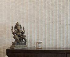
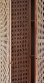
11. Rattan Pivot Door Panels
14
15
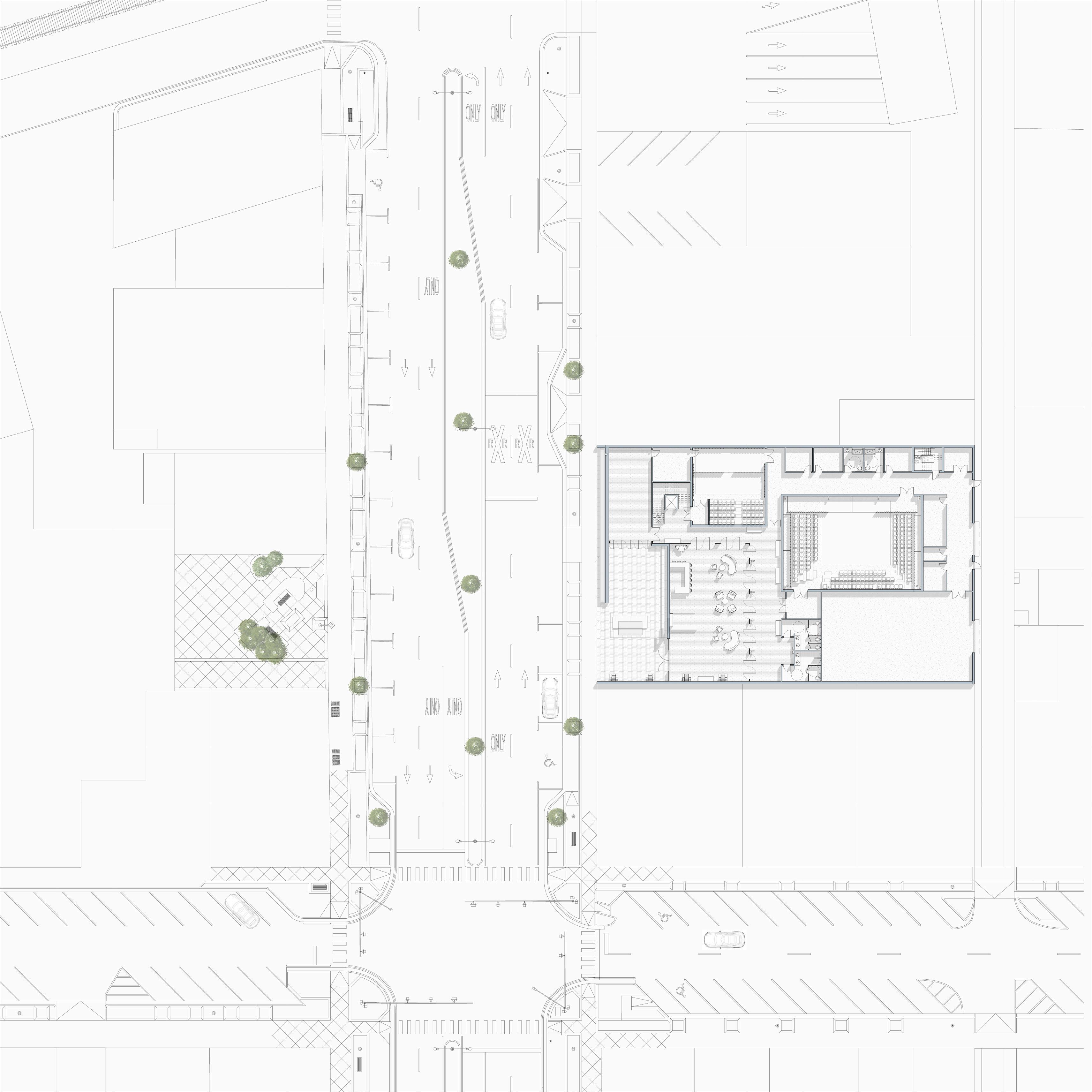
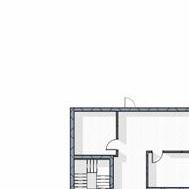
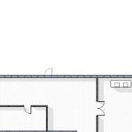
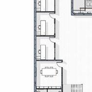
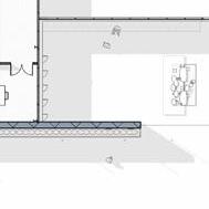
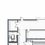
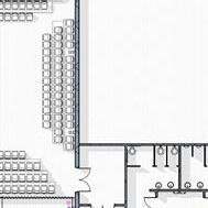
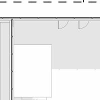
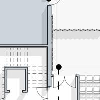
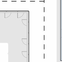
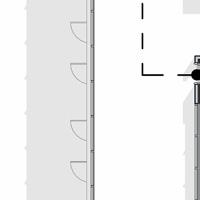
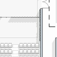
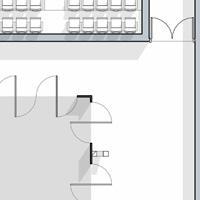
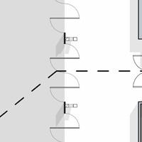
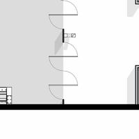
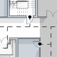
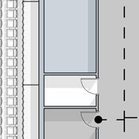
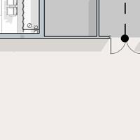
SITE PLAN + FLOORPLANS
16 LEVEL 1 1.
2.
3.
4.
5.
9.
10.
11.
12.
13.
1 5 4 3 2 3 10 9 8 7 6 7 8 9 13 12 11 12 11
Lobby
Public Restroom
Vestibule
Large Theatre
Small Theatre
6.
Rehearsal Studio
7.
Large Dressing Room 8. Small Dressing Room
BOH Restroom/Shower
Scene Shop
Back of House
Storage
Courtyard
14. Costume Shop
18.
19.
20.
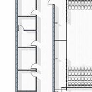
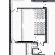
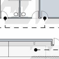
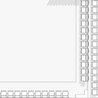
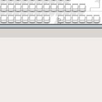
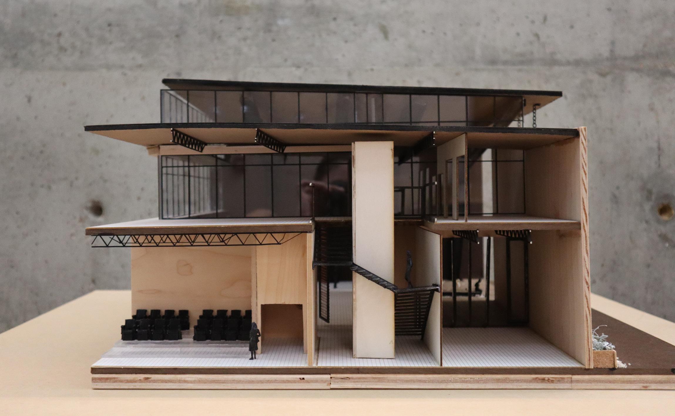
This final programmatic design with an integrated structure is a final result of the speculative model's central courtyard concept, emphasizing transparency and engagement with the public. Structural elements interact with the courtyard, defining the space while maintaining an open environment that does not feel too heavy. This integration of structure and design aligns with the programming gesture's emphasis on creating welcoming and visually engaging spaces for public interaction. Located on the first floor are both theaters and the rehearsal studio, all meant to be available to public users. Additionally on this level, you will find the 'Back of House' essentials such as the scene shop and 4 dressing rooms.
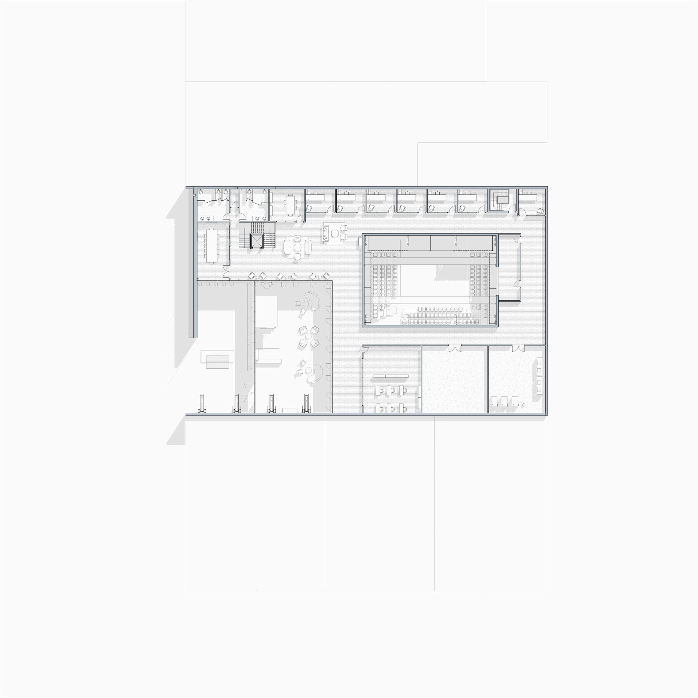
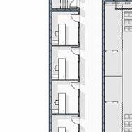
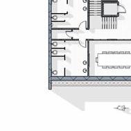
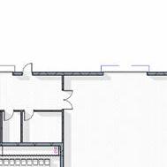
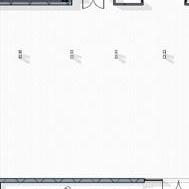
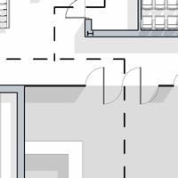
The second level of this design is quite simple yet very effective. While the first level features all of the public gathering spaces, including the courtyard, the upper level holds much of the private spaces. On level 2, one will find 7 offices, 2 conference rooms, and the costume shop. These spaces are available for a visitor to access when needed but with much intent, there is no grand stair to encourage wondering. This is ideal for a theatre during shows and for the employees who keep the building up. While viewing the floor plan below, you will notice 2 "open to below" annotations. The one found in the middle of the plan would be the large theatre, a 35' space allowing for ideal performance needs. The second 2-story space would be the lobby, with simple clerestory lighting and viewing from the office lobby.
17
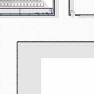
LEVEL 2
15. Office Lobby 16. Office 17. Large Conference Room
Small
Conference Room
Restrooms
Mechanical
Electrical
Theater Tech. Room 14 12 15 19 16 17 16 16 16 16 16 16 18 19 20 21 OPEN TO BELOW OPEN TO BELOW
&
21.
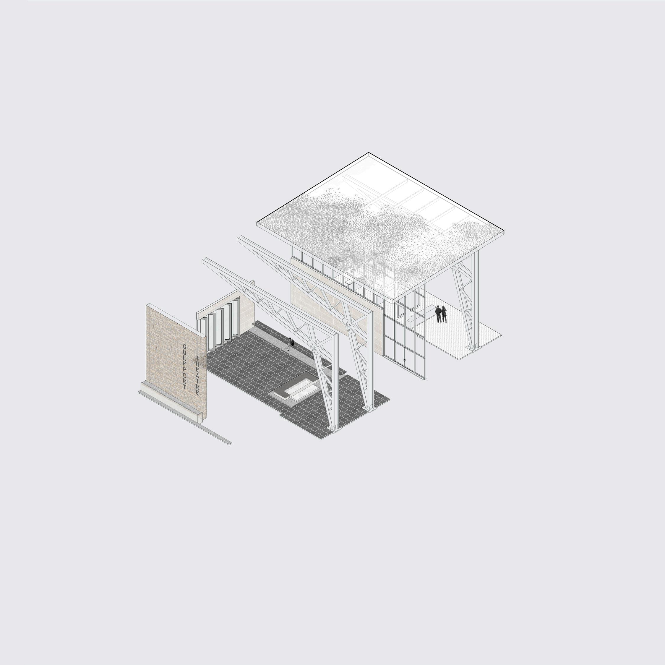
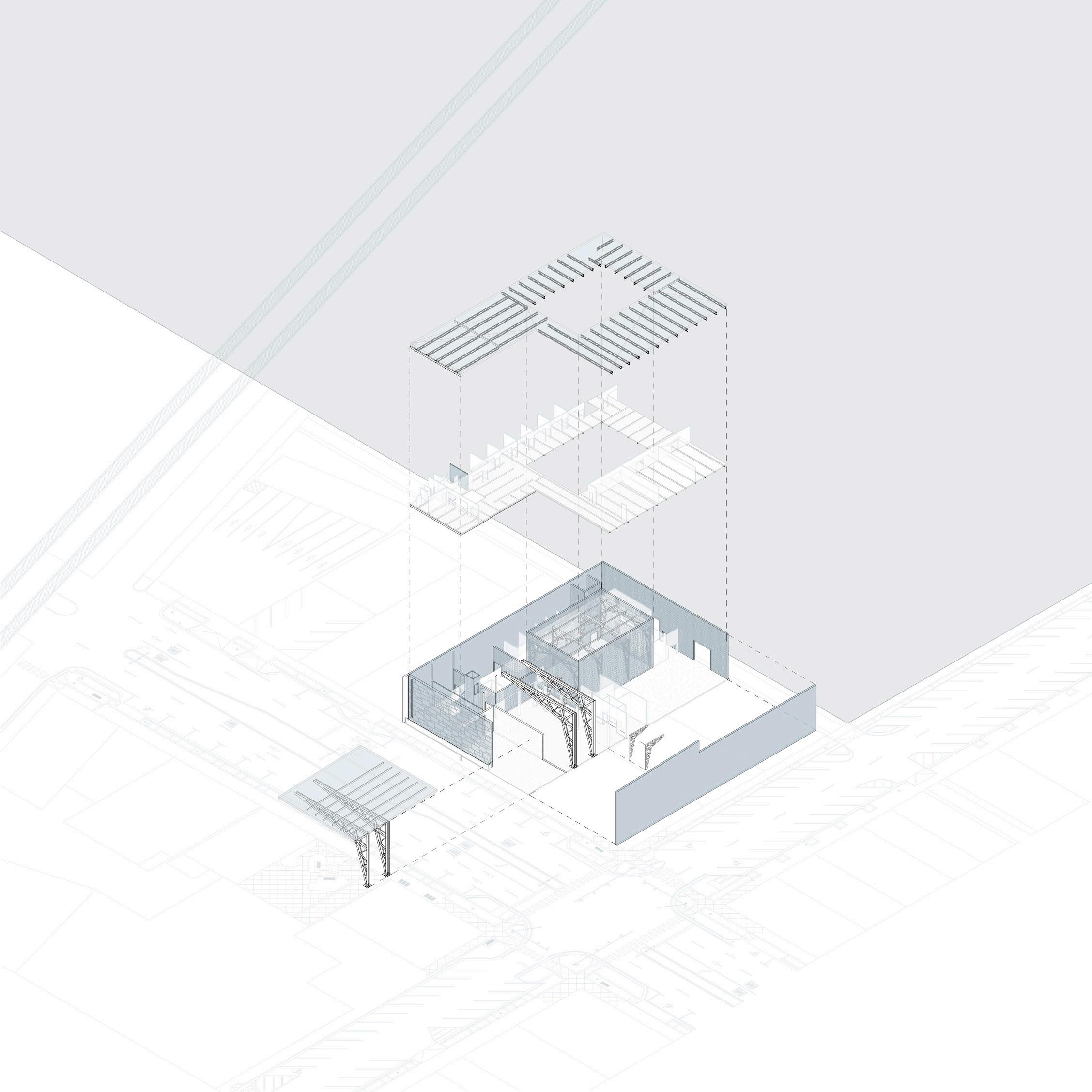
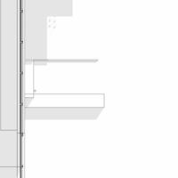
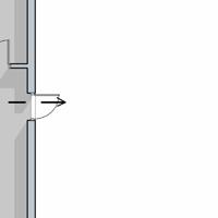
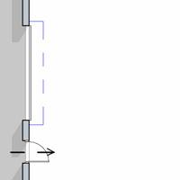
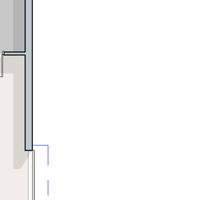
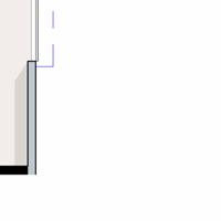
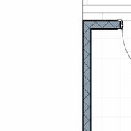
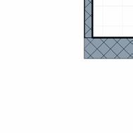
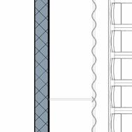
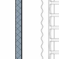
EXPLODED AXON: FACADE
Hardwood Flooring Steel Truss Exterior Glazing Porcelain Pavers Splitface Limestone Veneer Gray Slate Pebbles18
Smoothface Limestone Veneer
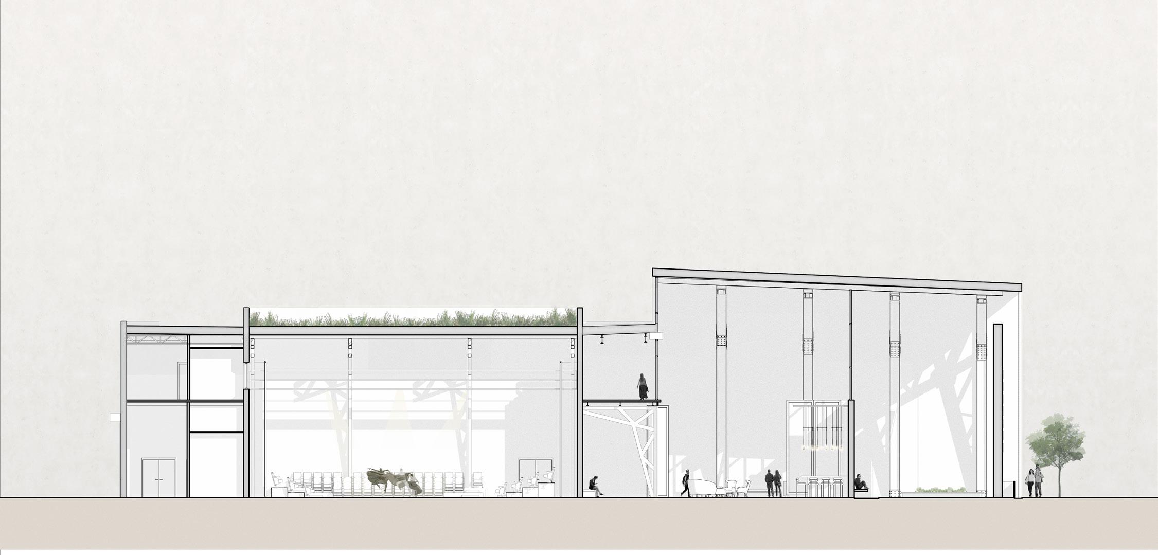
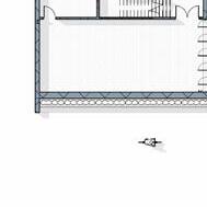
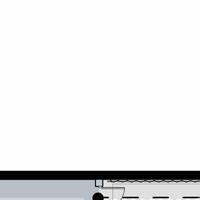
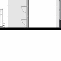
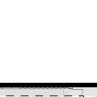
LONGITUDINAL SECTION
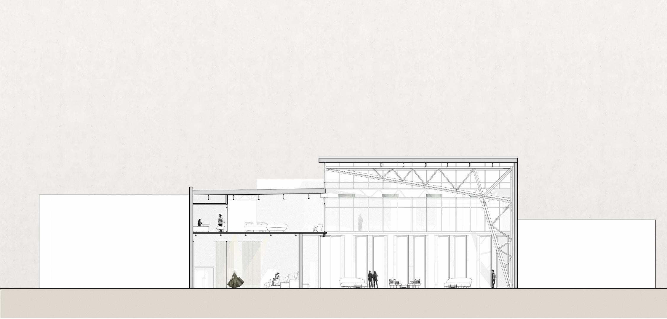
TRANSVERSE SECTION
19
20
21


Steel
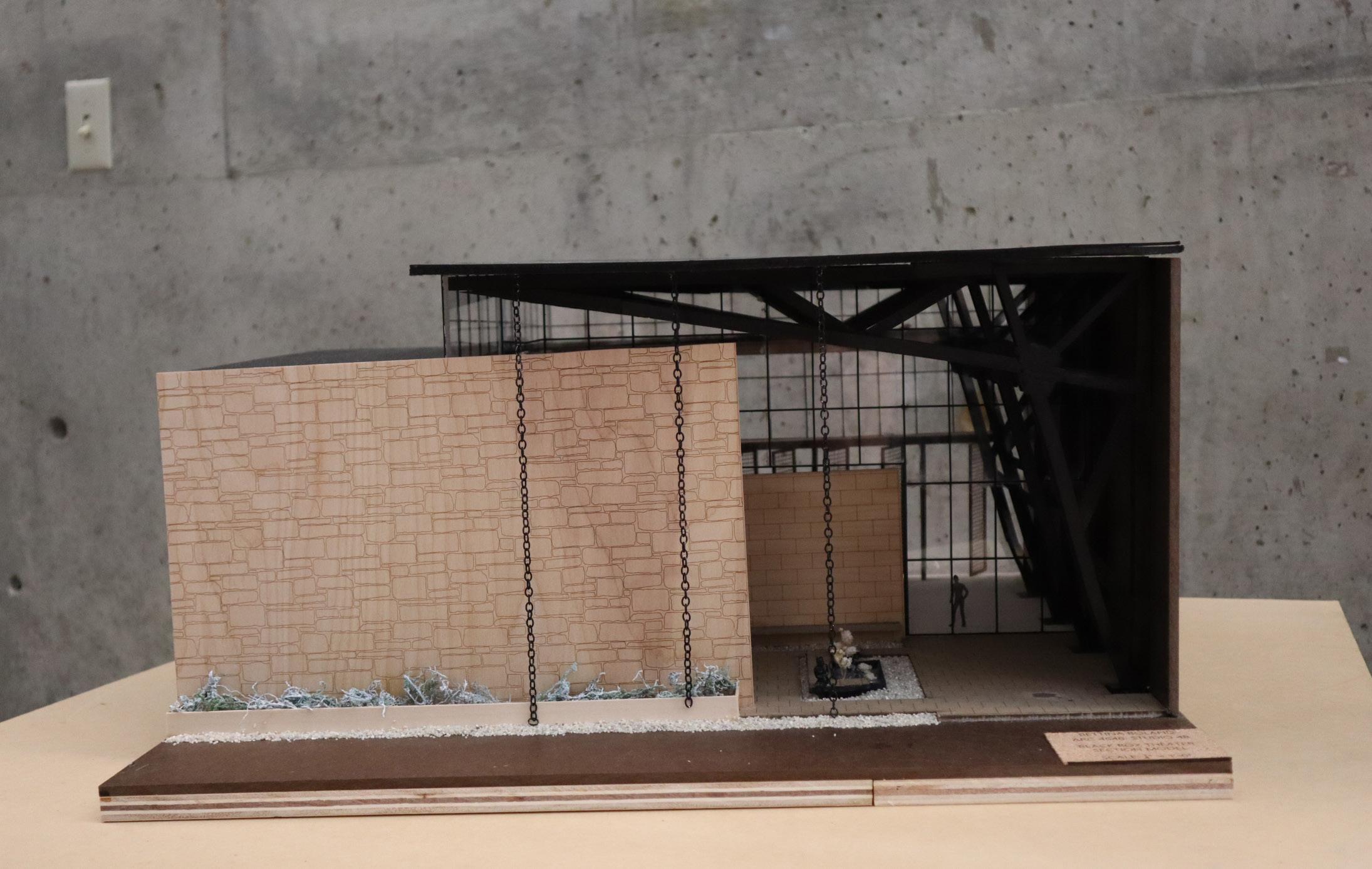
Split Stone, Courtyard Wall Elevated Curtain Wall Steel Truss Rain Chain Smooth Stone, Courtyard Wall Rainwater Collection Pivot Doors
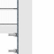
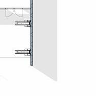
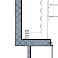
08 05 07 01 06 09 04 02 02 03 1. Galvanized Chain 2. Wood Blocking 3. Sealant 4. Drip Angle 5. Vapour Control Layer 6. Structural Deck Steel 7. Steel Purlin 8. Gutter 9. Flashing 05 04 07 06 03 01 08 11 03 02 02 09 3/4" 1/2" 1/2" 1. Standing Seam Profile 2. Compound Clip 3. Thermal Insulation 4. Thermal Insulation 5. Vapour Control Layer 6. Structural Deck Steel 7. Steel Purlin 8. Liner Tray 9. Omega Steel-Profiles 02 03 05 04 06 07 08 09 10 11 12 13 1. Window Frame 2. Sealant 3. Sill Pan 4. 2-7/8” Casing Bead 5. Flexible Flashing 6. Smoothface Stone Veneer 7. Contiuous Insulation with drainage channels 8. Building Paper 10. Self-furringmetal Lathater Barrier 11. Gypsum Sheathing 12. C-Channel Track 13. Cavity Insulation 14. Steel Stud 22
Purlins
DIPTYCH STUDY
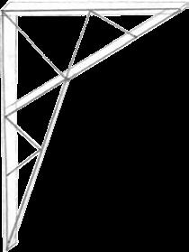
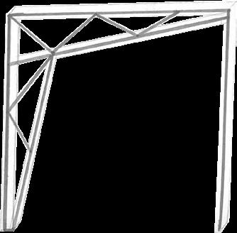
Resilient Truss
Structure:
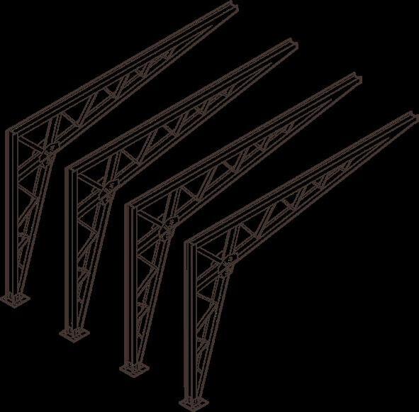
The scissor truss, serving as the primary structural element in the theater’s main spaces such as the lobby and the large theater, embodies exceptional resilience, particularly crucial in hurricane-prone regions. Its strength lies in the seamless transition from vertical to horizontal components, fortifying its ability to withstand the formidable forces of nature.
Steel Beams and Girders:
30’ span = 16” beam depth
Floor Joist:
12’ span = 5”-7” depth
16’-24’ span = 8”-11” depth
Steel Scissor Truss:
30’ span = 8’ depth
60’ span = 14’ depth
100’ span= 24’ depth
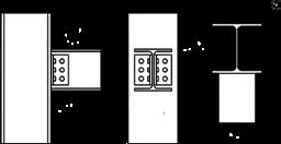
Cleat, Web connection will be the typical beam to column connector.
Plate, Gusset: Will make up a majority of the connections in the truss. Bolted to the members.
EXPLODED AXON: STRUCTURE

STRUCTURAL CMU WALL
The small and large theaters will be encased with a CMU wall, allowing for the versatile functions productions call for. Exterior structural members, such as beams, will be attached to the wall via steal bearing plates.
STRUCTURALPARTYWALL
Open-Web Joist: Light weight structural element, will use to support roof. The party wall, located on the north and sound side of the building, is an important structural element of this design. This wall includes a 6” Air Space, a 8” CMU Wall, and Gypsum Wall Board, along with the minor details required for construction.
EXTERIOR SCISSORTRUSS
DOUBLEHEIGHT SCISSORTRUSS
23
ACTIVE BUILDING SYSTEMS


ROOF PLAN


VAV System Components
Air-Cooled Chiller System 60 Tons
Condensing Boiler: 2000 MBH Heat Pump 6 Tons Ventilation System
Air Handling Unit: 10000 CFM
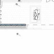
OPEN TO BELOW OPEN TO BELOW LEVEL 2 LEVEL 1
Terminal Unit
HVAC in Plan & Axonometric Air Supply Duct Air Supply Duct Air Return Duct Air Return Duct Air Return Duct
24
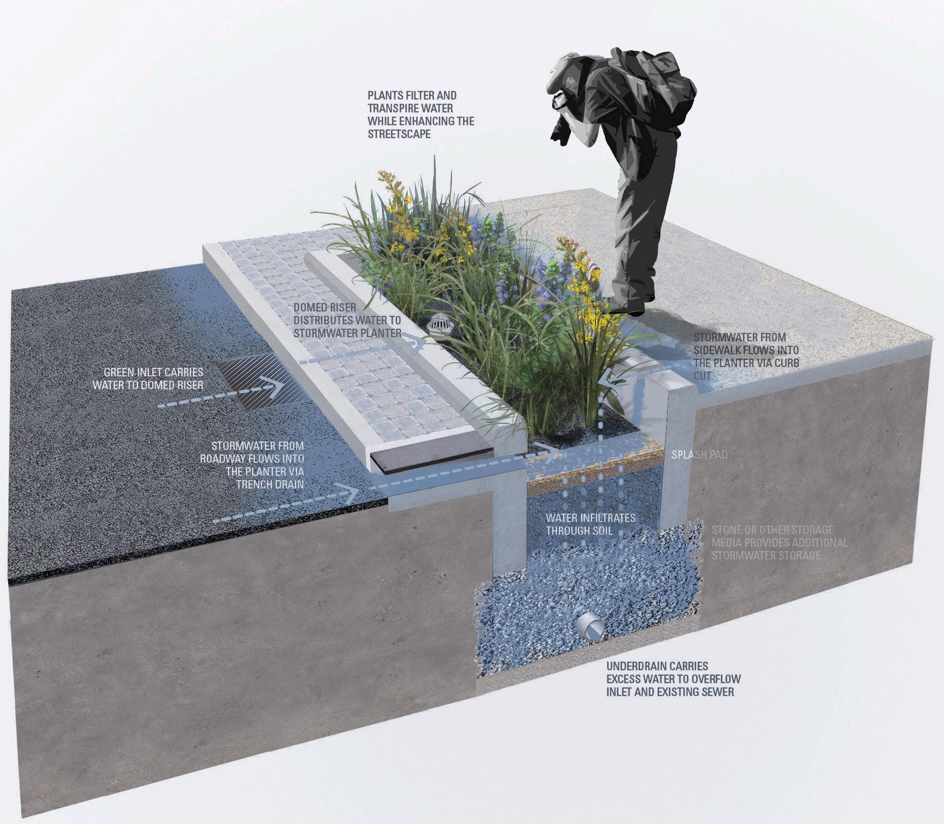
Stormwater Runoff

Stormwater Planter Diagram
0.38 2.98 4.25 1.27
Philadelphia Water Department Diagram
RESILIENCY & SUSTAINABILITY
1. LiveRoof Module
2. LiveRoof Engineered Soil
4. EPDM, TPO or PVC Waterproofing Membrane 3. Root Barrier / Protection Layer
5. Adhered or Mechanically Fastened Coverboard
1 2 4 5 6 3
6. Fully Adhered or Mechanically Fastened Insulation
Green Roof by LiveRoof : Standard LiveRoof Module System
25
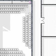
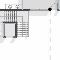
CODE & ACCESSIBILITY: BUILDING CODE ANALYSIS


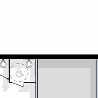


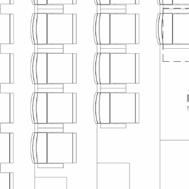
2605 SF SCENE SHOP 106 17 150 2469 SF LARGE THEATRE 105 142 7 999 SF SMALL THEATRE 104 46 7 792 SF REHERSAL ROOM 103 27 30 243 SF LARGE DRESS 106 5 50 226 SF LARGE DRESS 114 5 50 128 SF SMALL DRESS 111 3 50 124 SF SMALL DRESSING 107 3 50 136 SF LAUNDRY 108 3 50 131 SF STORAGE 112 0 300 582 SF BACK OF HOUSE 113 0 300 2125 SF LOBBY 102 251 15 1444 SF COURTYARD 75 SF VESTIBULE 178 SF VESTIBLE 191 SF MENS RESTRROM 194 SF WOMENS RESTROOM 60 SF CUSTODIAL 128 SF STORAGE 116 0 300 EXIT-1 435 OCCUPANCY EXIT-2 127 OCCUPANCY EXIT-3 22 OCCUPANCY 824 SF COSTUME SHOP 201 3 300 929 SF STORAGE 215 3 300 804 SF MECHANICAL AND ELECTRICAL 214 3 300 143 SF OFFICE 208 1 150 143 SF OFFICE 209 1 150 144 SF OFFICE 210 1 150 144 SF OFFICE 211 1 150 148 SF OFFICE 212 1 150 301 SF TEC. DECK 213 2 150 145 SF OFFICE 206 1 150 143 SF OFFICE 207 1 150 OPEN TO BELOW OPEN TO BELOW OPEN TO BELOW: EXTERIOR COURTYARD SECONDARY EGRESS STAIR PRIMARY EGRESS STAIR 237 SF SMALL CONFERENCE 216 14 15 393 SF LARGE CONFERENCE 217 28 15
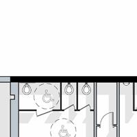
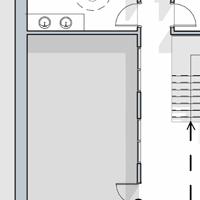
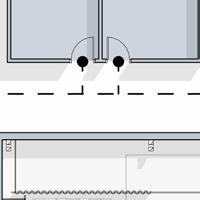
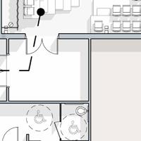
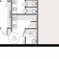
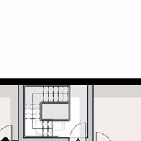
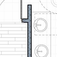
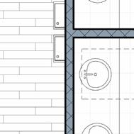
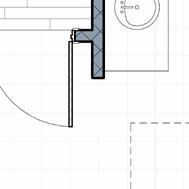
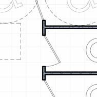
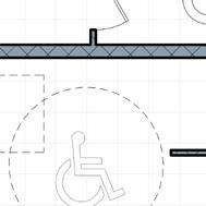
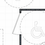
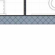
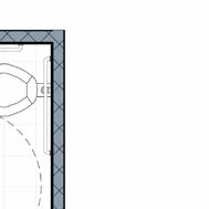
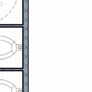
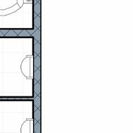
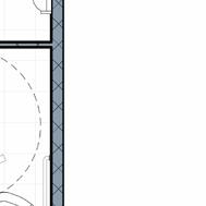
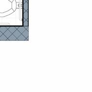
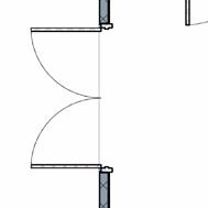
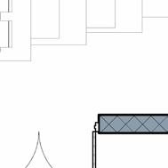
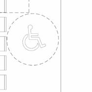
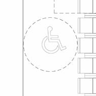
SECOND LEVEL FIRST LEVEL 60 min wheelchair turning space Baby Changing Station 19x33 inches down position 30 Clear Floor Space Clear Floor Space 5' - 2 3/4" 11' - 9 3/4" 7'1" 3' 0" 3'0" 3'0" 3'0" 7'1" 5' - 2 3/4" 11' - 4" 7'6" 7' 1" 5' - 8 1/2" 1' - 6" 1' - 6" 1'6" 1' 6" 1'6" min wheelchair turning space wheelchair turning space wheelchair turning space LOBBY RESTROOM: ADA PLAN 26
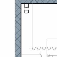


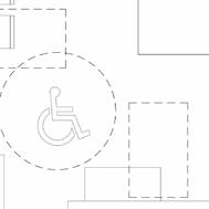


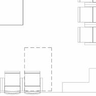

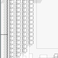
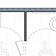
wheelchair turning space BACK STAGE 22'-11" x 22'-11" STAGE EXIT EXIT 41'0 3/4" 60' 6 1/4" 22' - 11" 22'11" 5'6" 4' - 0" 4' - 0 1/2" 2' - 6" 4'0 1/4" 15' 1 1/4" 11' 9 1/4" 3' - 3 1/2" 3' 0 1/2" 4'4" 5' - 4" 5' - 1 3/4" LARGE THEATER: ADA PLAN APPLICABLE CODES YEAR IBC International Building Code 2021 D. Type of Construction: VB ICC / ANSI 117.1 2009 * International Code Council (ICC) * American National Standard Institute (ANSI) Table 601 Fire-Resistance Rating Requirements Building Element A. Occupancy Group(s): A1 B F1 S2 - Structural Frame Change in Use: Yes Mixed Occupancy: Yes Exterior Bearing Walls Interior Bearing Walls Nonbearing Walls and Interior Partitions B. Special Use and Occupancy (eg. High Rise, Covered Mall): Yes Floor Construction (supporting beams Roof (beams and joists) C. General Building Height & Areas: Table 602 Allowable Height 40 ft Table 504.3 Fire Resistance Rating Allowable Stories 1 Table 504.4 Requirements for Exterior Walls based on the North South Automatic Sprinkler System Increase: Rating in hours 0 0 Building Height Increase: 20 ft Table 504.3 Distance in feet x' x' Number of Stories Increase: 1 Table 504.3 Allowable Area Table 506.2 E. Fire Protection Systems: Allowable Area (Aa) 16,500 sq. ft. Automatic Sprinkler Systems: Equation 5-1 Aa = At + (NS × If) For single story Is an Auto. Sprinkler Sys. required for Equation 5-2 Aa = [At + (NS × If)] × Sa For multi-story Are you providing an Auto. Sprinkler Sys.? At NS If F. Means of Egress: Sa Occupant Load Calculations: Actual Building Stats Actual Total Building Stories 2 Actual Total Height ft Total Building Occupancy = 584 Actual Total Building Area sf Main Level sf Means of Egress Sizing: Second Level sf Stairways: IBC 1005.3.1Occupant Load Third Level sf Other: IBC 1005.3.2 Occupant Load Fourth Level sf Fifth Level sf Stair Width Provided Sixth Level sf Corridor Width Exits from Stories: Minimum Number Number of Exits IBC Chapter 3 IBC Chapter 4 IBC Chapter 5 CODE ANALYSIS WORKSHEET Project Name: Preparer: Date: Gulfport Black Box Theatre Bettina Boland 3/25/24 IBC Chapter 6 IBC Chapter 10 IBC Chapter 9 *room sf / occupant *Add all room occupant Building Occupancy. 30 9,200 15,740 24,940 OCCUPANT LOAD WORKSHEET NAME: Bettina Boland DATE: 3/25/2024 ROOM # ROOM NAME FUNCTION SQUARE FOOTAGE NET/GROSS OCC. LOAD FACTOR 102 Lobby Assembly 3,763 NET 15 251 104 Small Theatre Assembly w/o fixed seating (concentrated) 360 NET 7 51 105 Large Theatre Assembly w/o fixed seating (concentrated) 800 NET 7 114 106 Large Dressing Room 1 Locker Rooms 245 GROSS 50 5 114 Large Dressing Room 2 Locker Rooms 226 GROSS 50 5 107 Small Dressing Room 1 Locker Rooms 125 GROSS 50 3 111 Small Dressing Room 2 Locker Rooms 129 GROSS 50 3 108 Laundry Locker Rooms 135 GROSS 50 3 201 Costume Shop Mercantile (Storage,Stock) 827 GROSS 300 3 103 Rehersal Studio Assembly w/o fixed seating 804 NET 30 27 113 Back of House (Loading) Accessory Storage Area 143 GROSS 300 0 112,116 Storage Level 1 Accessory Storage Area 260 GROSS 300 1 215 Storage Level 2 Accessory Storage Area 930 GROSS 300 3 214 Mechanical Mechanical Equipment Room 805 GROSS 300 3 202 Small Conference Room Assembly w/o fixed seating (unconcentrated) 208 NET 15 14 203 Large Conference Room Assembly w/o fixed seating (unconcentrated) 416 NET 15 28 205 Office Lobby Buisness Area 1,386 NET 150 9 206 Office 1 Buisness Area 144 NET 150 1 207 Office 2 Buisness Area 144 NET 150 1 208 Office 3 Buisness Area 144 NET 150 1 209 Office 4 Buisness Area 144 NET 150 1 210 Office 5 Buisness Area 145 NET 150 1 211 Office 6 Buisness Area 145 NET 150 1 212 Office 7 Buisness Area 149 NET 150 1 106 Scene Shop Buisness Area 2,609 GROSS 150 17 213 Tech Deck Buisness Area 258 NET 150 2 5 0 Small Theatre: Seats Available: 58 5 0 Large Theatre: Seats Available: 142 5 0 5 0 5 0 5 0 5 0 5 0 5 0 5 0 5 0 5 0 5 0 5 0 5 0 5 0 5 0 5 0 5 0 5 0 5 0 5 0 5 0 5 0 5 0 5 0 5 0 5 0 5 0 547 TOTAL OCCUPANT LOAD OCCUPANCY LOAD TOTAL OCCUPANCY LOAD: 547 APPLICABLE CODES YEAR IBC International Building Code 2021 D. Type of Construction: VB G. Plumbing Fixtures: ICC / ANSI 117.1 2009 Minimum Number of Required Plumbing * International Code Council (ICC) Occupancy A1 * American National Standard Institute (ANSI) Table 601 Water Closets: Fire-Resistance Rating Requirements for Building Elements (hrs): Lavatories: Building Element Hrs Bathtubs or Showers: A. Occupancy Group(s): A1 B F1 S2 - Structural Frame 0 Drinking Fountains: Change in Use: Yes Mixed Occupancy: Yes Exterior Bearing Walls 0 Other: Interior Bearing Walls 0 Complete this portion for Mixed-Use Occupancies Nonbearing Walls and Interior Partitions 0 Secondary Occupancy B B. Special Use and Occupancy (eg. High Rise, Covered Mall): Yes Floor Construction (supporting beams and joists) 0 Water Closets: Roof (beams and joists) 0 Lavatories: Bathtubs or Showers: C. General Building Height & Areas: Table 602 Drinking Fountains: Allowable Height 40 ft Table 504.3 Fire Resistance Rating Other: Allowable Stories 1 Table 504.4 Requirements for Exterior Walls based on the fire separation distance (in hours): North South East West Automatic Sprinkler System Increase: Rating in hours 0 0 0 0 H. Notes and Other Applicable Code Information: Building Height Increase: 20 ft Table 504.3 Distance in feet x' x' x' x' Number of Stories Increase: 1 Table 504.3 Allowable Area Table 506.2 E. Fire Protection Systems: Allowable Area (Aa) 16,500 sq. ft. Automatic Sprinkler Systems: IBC 903.2 Equation 5-1 Aa = At + (NS × If) For single story Is an Auto. Sprinkler Sys. required for your occupant group? Yes Equation 5-2 Aa = [At + (NS × If)] × Sa For multi-story Are you providing an Auto. Sprinkler Sys.? Yes At NS If F. Means of Egress: Sa Occupant Load Calculations: Table 1004.1.2 Actual Building Stats Actual Total Building Stories 2 Actual Total Height ft Total Building Occupancy = 584 Actual Total Building Area sf Main Level sf Means of Egress Sizing: IBC 1005 Second Level sf Stairways: IBC 1005.3.1Occupant Load * 0.3in. = 18 in Third Level sf Other: IBC 1005.3.2 Occupant Load * 0.2in. = in Fourth Level sf Fifth Level sf Stair Width Provided = 44 in Sixth Level sf Corridor Width Provided = 76 in Exits from Stories: IBC 1021.2 Minimum Number of Required Exits = 2 Number of Exits Provided = 2 IBC Chapter 3 IBC Chapter 4 IBC Chapter 5 CODE ANALYSIS WORKSHEET Project Name: Preparer: Date: Gulfport Black Box Theatre Bettina Boland 3/25/24 See IBC 602.2, 602.3, 602.4, 602.5 IBC Chapter 6 IBC Chapter 10 Male:1 Female:2 n/a Male:1 Female:1 2 Male:2 Female:2 Male:1 Female:1 IBC Chapter 9 n/a 1 *room sf occupant load factor = room occupant load *Add all room occupant loads together to generate Total Building Occupancy. IBC Chapter 29 30 9,200 15,740 24,940 APPLICABLE CODES YEAR IBC - International Building Code 2021 D. Type of Construction: VB G. Plumbing Fixtures: Table 2902.1 ICC / ANSI 117.1 2009 Minimum Number of Required Plumbing Fixtures: * International Code Council (ICC) Occupancy A1 * American National Standard Institute (ANSI) Table 601 Water Closets: Fire-Resistance Rating Requirements for Building Elements (hrs): Lavatories: Building Element Hrs Bathtubs or Showers: A. Occupancy Group(s): A1 B F1 S2 - Structural Frame 0 Drinking Fountains: Change in Use: Yes Mixed Occupancy: Yes Exterior Bearing Walls 0 Other: Interior Bearing Walls 0 Complete this portion for Mixed-Use Occupancies Nonbearing Walls and Interior Partitions 0 Secondary Occupancy B B. Special Use and Occupancy (eg. High Rise, Covered Mall): Yes Floor Construction (supporting beams and joists) 0 Water Closets: Roof (beams and joists) 0 Lavatories: Bathtubs or Showers: C. General Building Height & Areas: Table 602 Drinking Fountains: Allowable Height 40 ft Table 504.3 Fire Resistance Rating Other: Allowable Stories 1 Table 504.4 Requirements for Exterior Walls based on the fire separation distance (in hours): North South East West Automatic Sprinkler System Increase: Rating in hours 0 0 0 0 H. Notes and Other Applicable Code Information: Building Height Increase: 20 ft Table 504.3 Distance in feet x' x' x' x' Number of Stories Increase: 1 Table 504.3 Allowable Area Table 506.2 E. Fire Protection Systems: Allowable Area (Aa) 16,500 sq. ft. Automatic Sprinkler Systems: IBC 903.2 Equation 5-1 Aa = At + (NS × If) For single story Is an Auto. Sprinkler Sys. required for your occupant group? Yes Equation 5-2 Aa = [At + (NS × If)] × Sa For multi-story Are you providing an Auto. Sprinkler Sys.? Yes At NS If F. Means of Egress: Sa Occupant Load Calculations: Table 1004.1.2 IBC Chapter 3 IBC Chapter 4 IBC Chapter 5 CODE ANALYSIS WORKSHEET Project Name: Preparer: Date: Gulfport Black Box Theatre Bettina Boland 3/25/24 See IBC 602.2, 602.3, 602.4, 602.5 IBC Chapter 6 IBC Chapter 10 Male:1 Female:2 n/a Male:1 Female:1 2 Male:2 Female:2 Male:1 Female:1 IBC Chapter 9 n/a 1 *room sf occupant load factor = room occupant load IBC Chapter 29 27
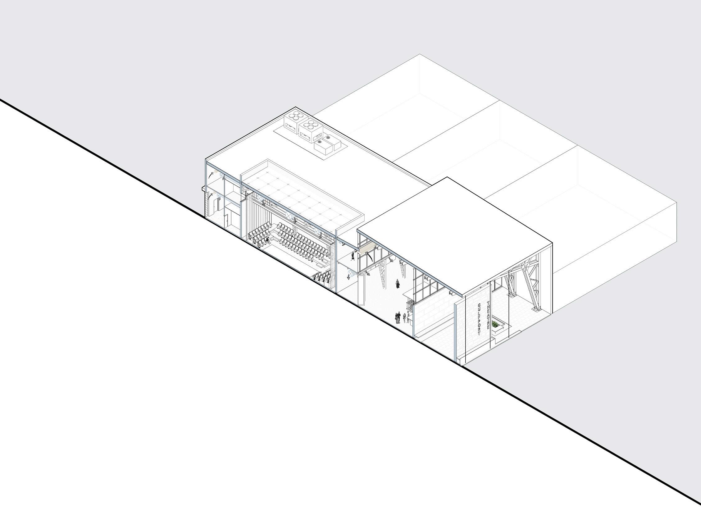
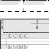
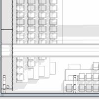
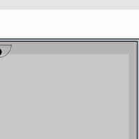
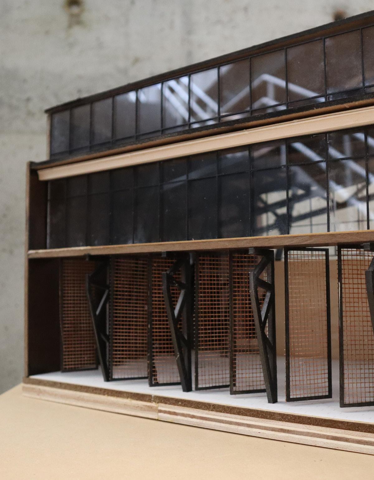
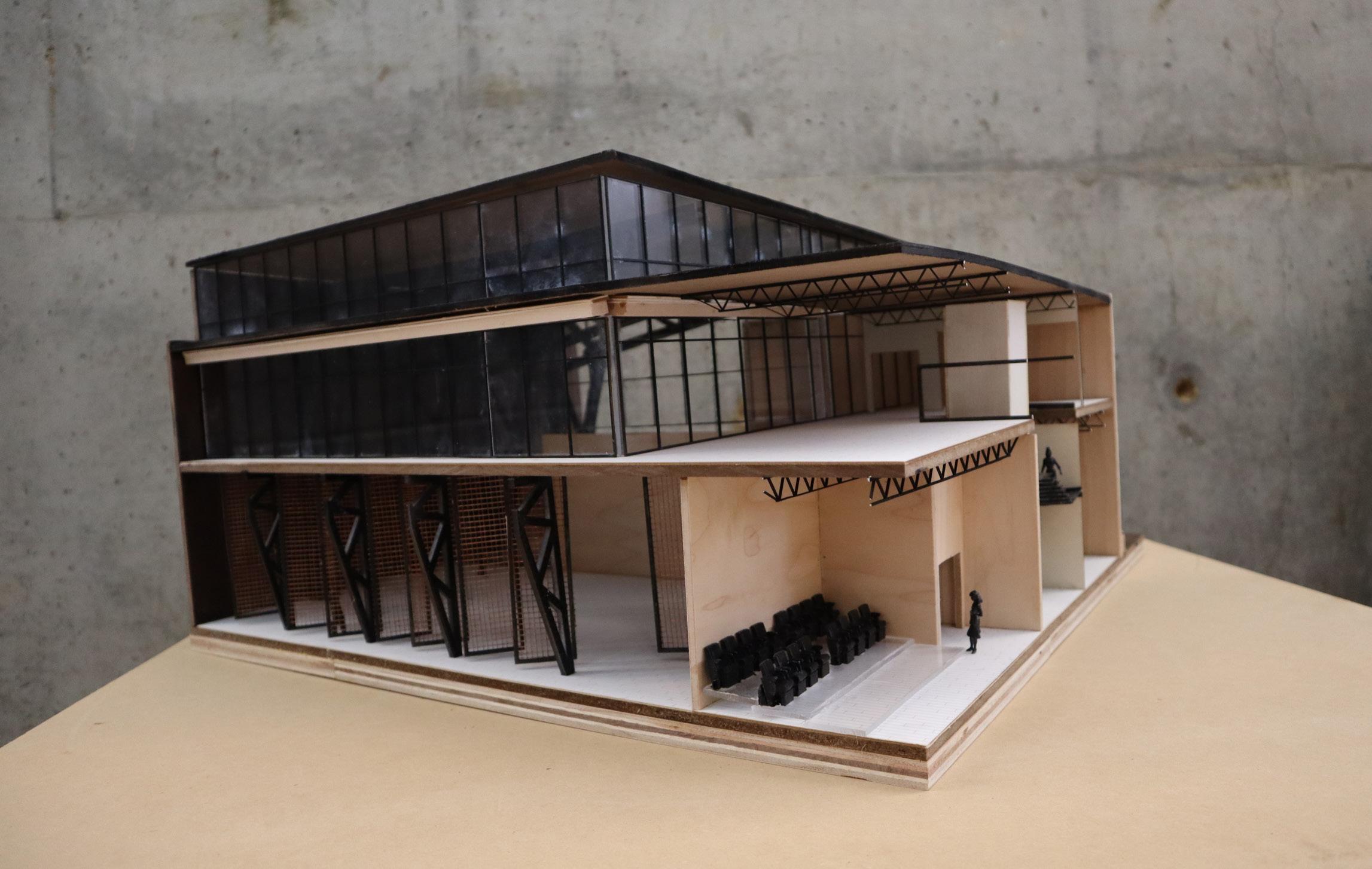
SECTION MODEL
SCALE: 1/4" = 1'-0"
28
29
30
31
ARC 4546 ARCHITECTURAL DESIGN IV-B
SPRING 2024
PROFESSOR HERRMANN
FINAL SEMESTER PROJECT
BETTINA BOLAND