PORTFÓLIO
BARBARA SULA BRAGA

Arquiteta e Urbanista com foco em estudos urbanos. Habilidades em produção e análise de dados geográficos. Possuo experiência administrativa e organizacional, com projeto e gestão de obra. Valorizo o trabalho multidisciplinar e em equipe, assim como a importância do processo criativo e de inovação. Estou sempre em busca de novos aprendizados.
+ 55 11 991909960 t e in in/barbarasula
barbarasulab@gmail.com
Rua Salvador de Pontes, 02 | 02375-060 São Paulo - SP, Brasil | 25 anos
Idiomas
Inglês Avançado / aulas particulares - cursando
Alemão Pré-Avançado / certificado TUBerlin B2.1
Espanhol Intermediário / aulas particulares - cursando
Português Nativo
Interesses
Viagem, Voleibol, Pintura
Conhecimentos
Softwares/Proficiência
Revit
Qgis
AutoCad
InDesign
Photoshop
Illustrator

Navisworks
Excel
ArchiCad
Experiência Profissional Histórico Acadêmico
02/2016 - 07/2022
Bacharelado - Arquitetura e Urbanismo / São Paulo
USP - Universidade de São Paulo
TFG: Sinergia entre transporte de alta capacidade e modos ativos: Implicações no térreo urbano
09/2019 - 03/2020
Intercâmbio - Mestrado em Urban Design / Berlim
23 ECTS
TU Berlin - Technische Universität Berlin
07/2020 - 07/2020
Unravelling the Cycling City / 30h Coursera, Universiteit van Amsterdam
07/2020 - 08/2020
European Studies / 45h
Ludwig-Maximilians-Universität München
07/2018 - 08/2018
European City and Regional Planning / Berlim 45h
Língua Alemã / Berlim 45h
Humboldt Universität zu Berlin
01/2013 - 02/2013
Língua Inglesa / Ann Arbor, Michigan 100h
Michigan Language Center
09/2020-Arquiteta e Urbanista
-Estagiária - Arquitetura e Urbanismo
23Sul Arquitetura e Urbanismo
03/2019 - 08/2020
Assistente de Projeto - Projeto de escritório e laboratório
Inside Diagnósticos
Pesquisa, Extensão e Trabalho
Voluntário
04/2021 - 06/2022
MoveEP
Grupo de extensão universitária com foco em estudos de mobilidade
02/2016 - 07/2017
Grupo de construção Agroecológica FAU USP
Pesquisa e Extensão voluntária: Assistência técnica em assentamento rural
05/2017 - 10/2018
GAIA FAU USP
Bolsa de Pesquisa e Extensão: “Território da Autonomia: Acesso a terra e participação Social”
02/2012-12/2015
Ensino Médio integrado ao Técnico em Mecânica
IFSP - Instituto Federal de São Paulo
02/2018 - 07/2018
Monitoria Voluntária: Disciplina “Planejamento Urbano: Estruturas”
TRABALHOS DESENVOLVIDOS NAS ÁREAS DE DESENHO URBANO E MOBILIDADE
LISTA DE PROJETOS
CYCLE INFRASTRUCTURE AND THE URBAN GROUND FLOOR
Synergy between high-capacity transport and active modes: implications on the urban ground floor
CYCLE PLAN STRATEGY: SÃO PAULO | Final Essay
CICLOMOBILIDADE | Jaçana - Tremembé
BRT CUIABÁ | 23 Sul
ESTUDO DE IMPLANTAÇÃO DE VLT | EGIS
SERPENTINA | The re-contact with nature
SPINE | Integrating housing in an industrial area
PARQUE DE VÁRZEA JD. HELENA | Recuperação da várzea do Tietê
PORTO FLUVIAL DE PASSAGEROS | Transição e transporte
CYCLE INFRASTRUCTURE AND THE URBAN GROUND FLOOR
Synergy between high-capacity transport and active modes: implications on the urban ground floor
Local: Tucuruvi, São Paulo
SP - Brazil
The main objective of this work is to understand how the integration between active modes and high-capacity transport happens on the outskirts of large urban centers, focusing on the city of São Paulo, and how the urban ground floor applies a bilateral influence on this system. Based on the study by Lucas Harm and Roland Kager “Synergies from Improved Cycling-Transit Integration, Towards an integrated urban mobility system” and the concept of David Mangin’s “Rez-de-Vil-
final undergraduate project
FAU-USP individual work
Oriented by João Sette Whitaker 2022
For the full version visit: Project (portuguese)
le”, the aim is to reflect on the problem known as “First Mile and Last Mile Problem”, which deals with access to trunk public transport. Additionally to the modal chosen to access high-capacity or fast transport, an important point of attention is how the socially and politically built environment in cities induces choices over people, having the ground floor as the stage of urban life.
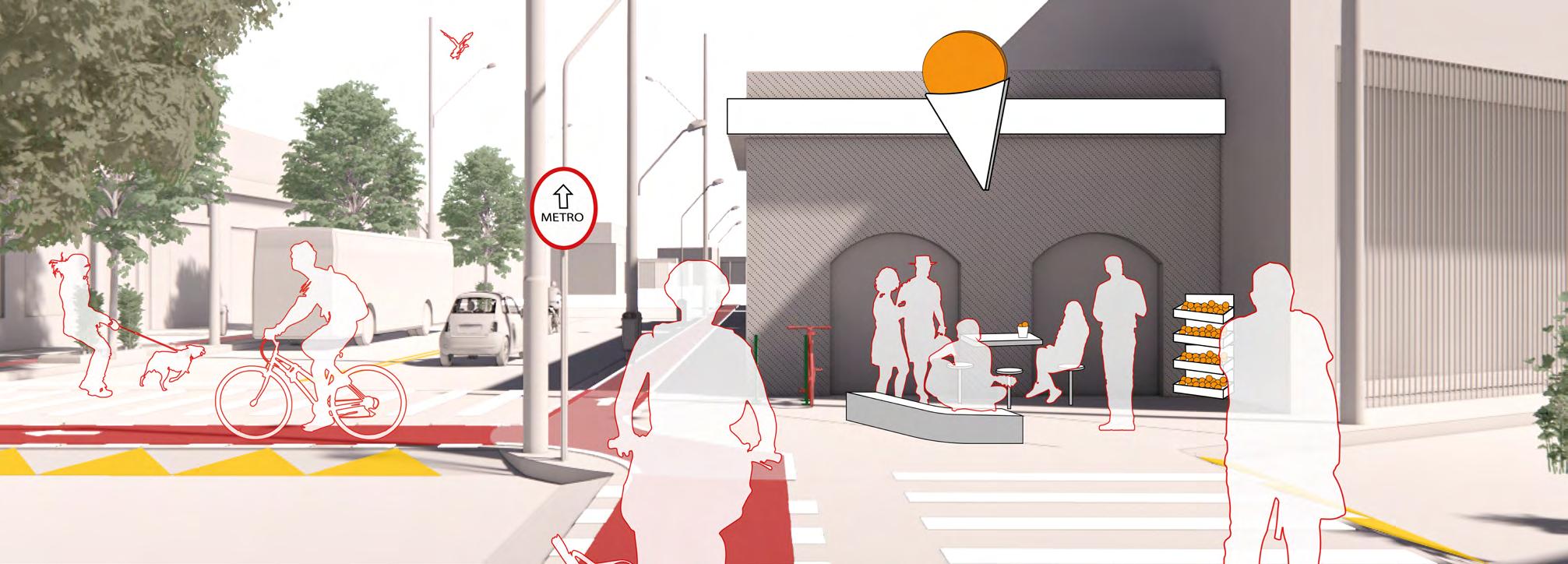
Given this, the aim is to understand how the urban design, the treatment of the ground floor,
66,1% 33,9% 67,3% 32,7% 2007 2017 NON-MOTORIZED MODES MOTORIZED MODES 1977 1977 MOTORIZED TRAVELS - OD SURVEY São Paulo NON-MOTORIZED TRAVELS - OD SURVEY São Paulo 2007 2007 2017 2017 MOTORIZED TRAVEL – OD SURVEY 1977 37,2% INDIVIDUAL 62,8% COLLECTIVE 2007 44,7% INDIVIDUAL 55,3% COLLECTIVE 45,9% INDIVIDUAL 54,1% COLLECTIVE 2017 NON-MOTORIZED TRAVEL – OD SURVEY 1977 1,2% BICYCLE 98,8% ON FOOT 2007 2,4% BICYCLE 97,6% ON FOOT 2,7% BICYCLE 97,3% ON FOOT MOTORIZED
1977 37,2% INDIVIDUAL 62,8% COLLECTIVE 2007 44,7% INDIVIDUAL 55,3% COLLECTIVE 45,9% INDIVIDUAL 54,1% COLLECTIVE 2017 NON-MOTORIZED
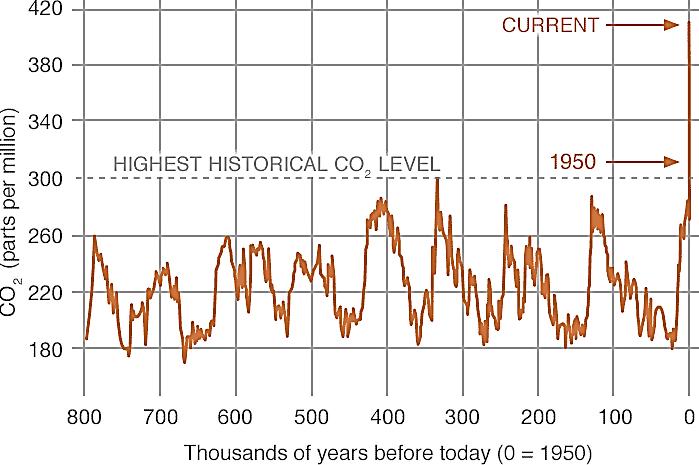
SURVEY 1977 1,2% BICYCLE 98,8% ON FOOT 2007 2,4% BICYCLE 97,6% ON FOOT 2,7% BICYCLE 97,3% ON FOOT CO2
glacial
Modal division in São Paulo. Data: OD Survey - SP Metro.
TRAVEL – OD SURVEY
TRAVEL – OD
levels during Earth’s last three
cycles. Source: NOAA, NASA
and the use of the land incite unique relationships between environment and mobility. The choice of the bicycle is not arbitrary, it is due to its ability to be competitive with motorized modes in distances up to 5 kilometers, given its speed. Encouraging the use of non-CO2-emitting transport is essential for sustaining life, to prevent the environmental and urban collapse of cities.
The study focuses on understanding how the bicycle can be inserted into the daily journeys of thousands of potential users who live near high-capacity transport stations and choose to use a car or feeder transport (in general, buses) to reach the nodal points of transport trunk lines.
Within the planning of the cycling network, it is possible to verify that, often due to the existing urban fabric, topographic conditions, or ease of
implementation, cycle paths are inserted on the main road transport routes, deliberately following the road logic, focused on automobiles. Particularly in the existent network, there is a tendency towards a radial connection between the periphery and the downtown area, following the layout of radial avenues at the bottom of the valleys that have developed as the main road connectors.
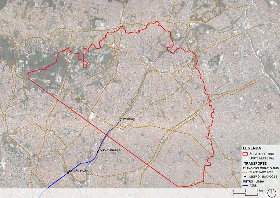
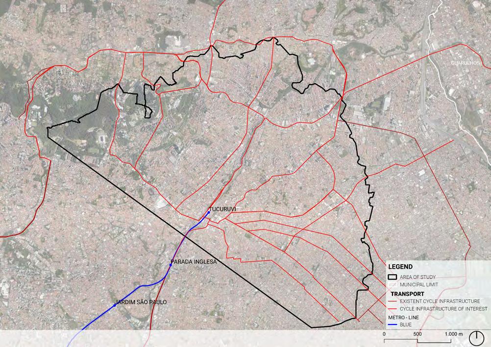
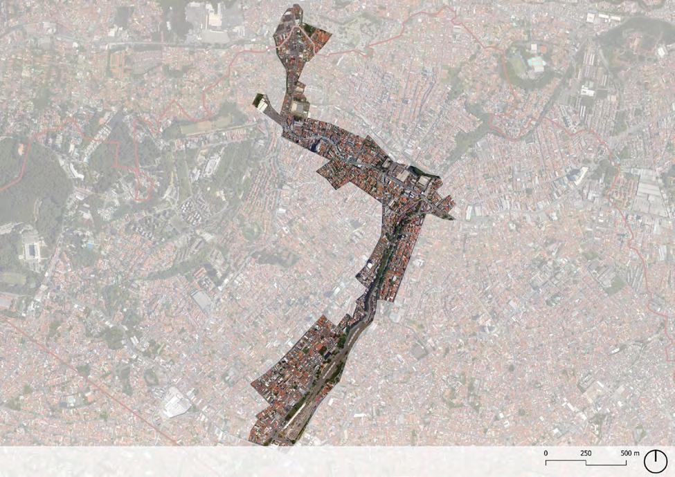
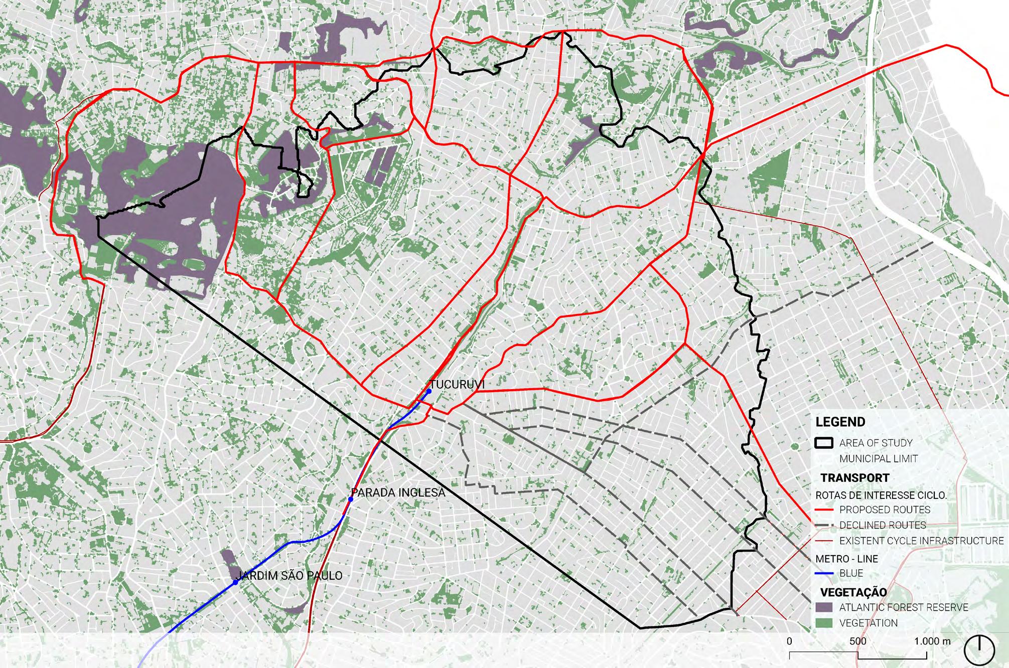
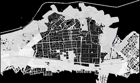
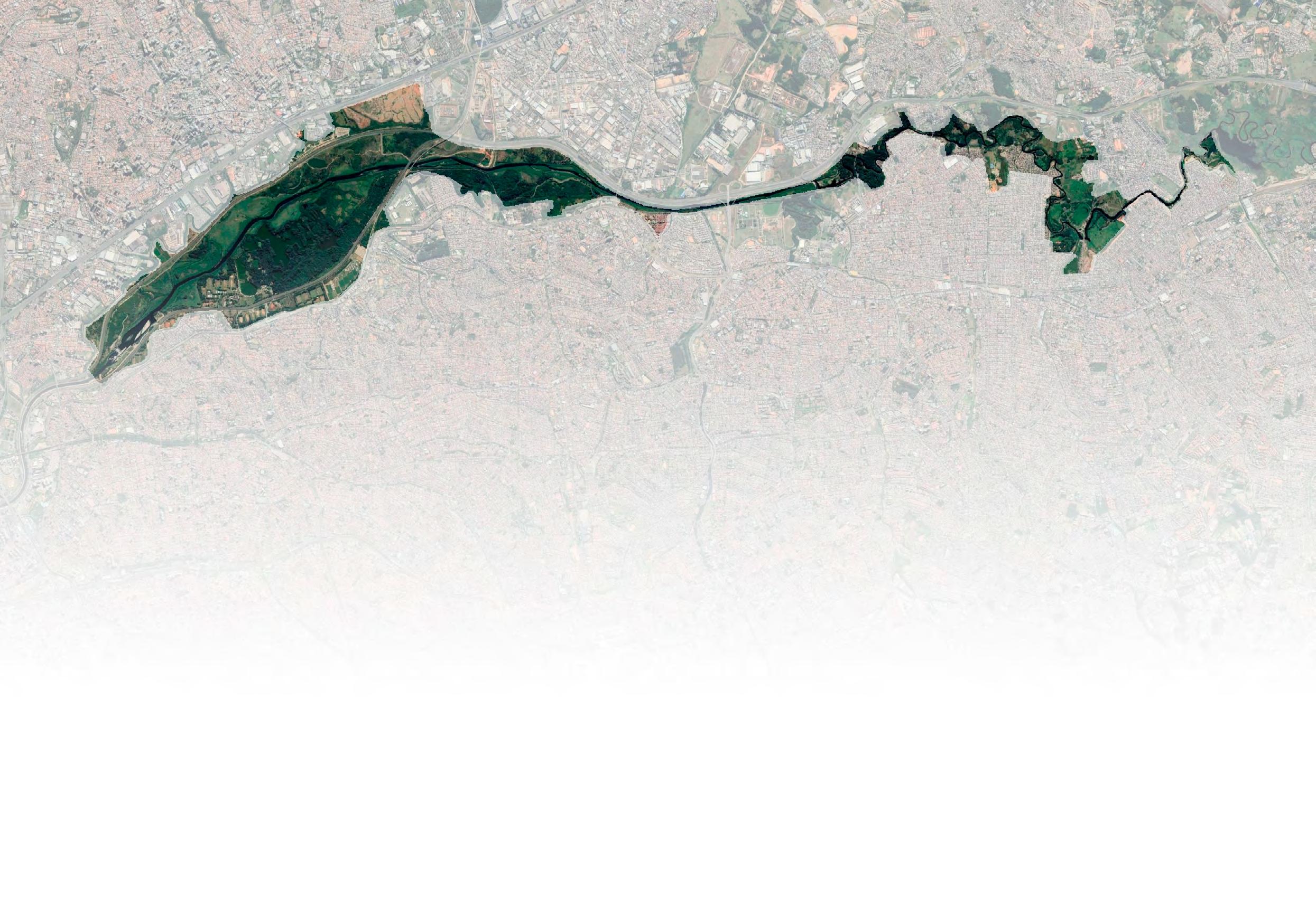
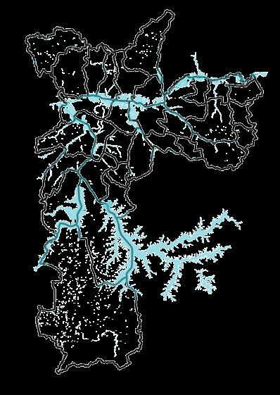
In this gap, the project is developed, proposing the implementation of cycle routes that connect points 15 minutes away from the Tucuruvi subway station, in the North Zone of the City of São Paulo. Based on the tracing of the routes, analyses are made to verify the possibility of implementation. Subsequently, a route was chosen as a case study to study the relationships of the urban ground floor from the design focused on active mobility.
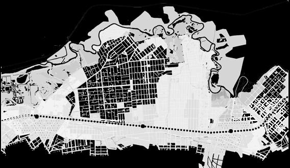
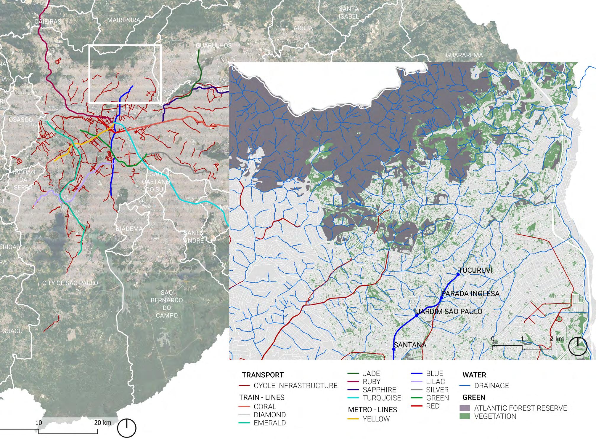 In the left, map of the City of São Paulo with metro, train and cycle infrastructure. In the right, zoom in the study region. Data: Geosampa.
DELIMITATION OF THE STUDY AREA AND TERRITORIAL ANALYSIS
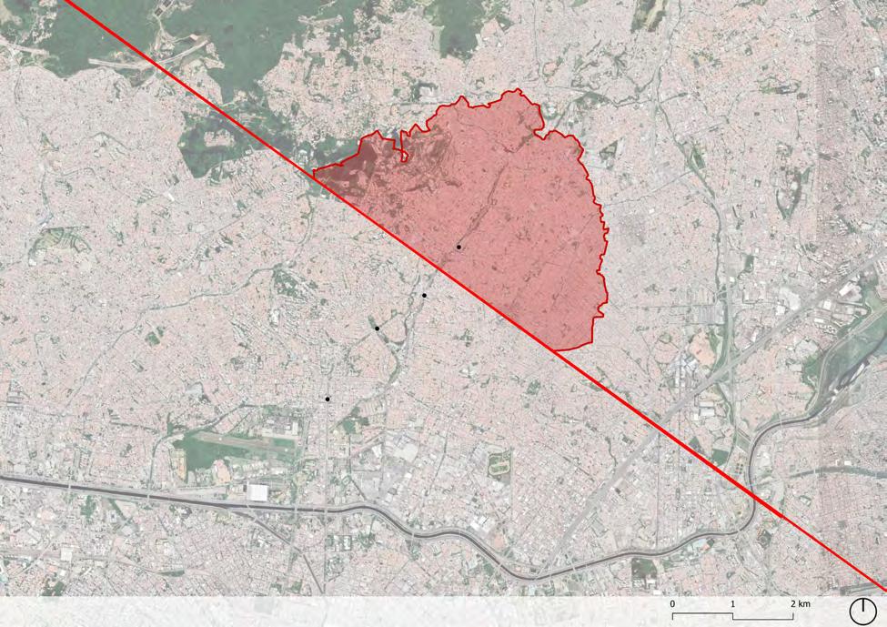
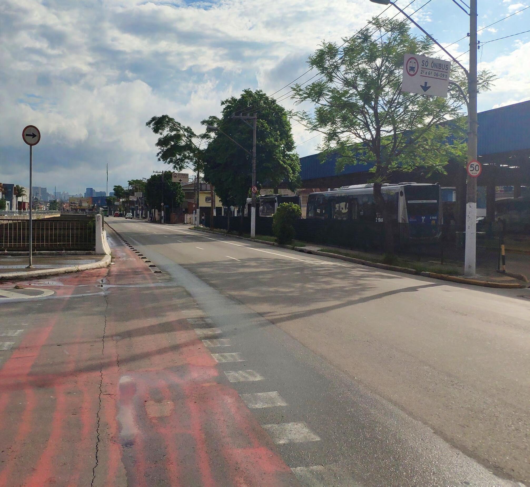
To determine the clipping of the study area, an average time of 15 minutes was established from the subway station and a study speed of 12 km/h. The speed was defined based on empirical tests in the region, with the help of the Strava application, it was possible to monitor the time and speed along main and secondary roads, and thus an average was determined.
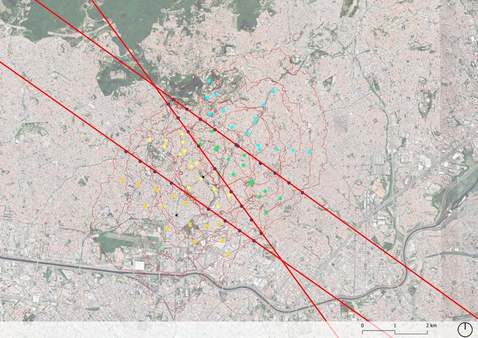
With these variables, isochronous lines were drawn based on the urban fabric. The speed and time parameters above mentioned were overlayed on the road structure, but without taking into account the direction of the roads, as the bicycle does not need to follow the directions defined for the cars.
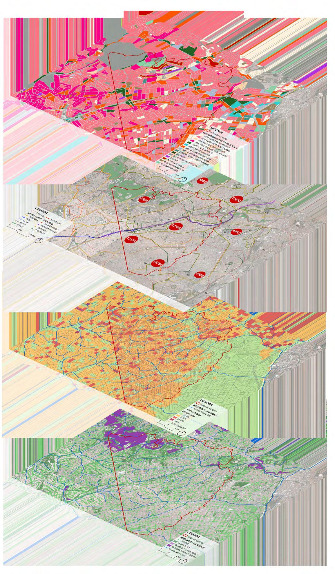
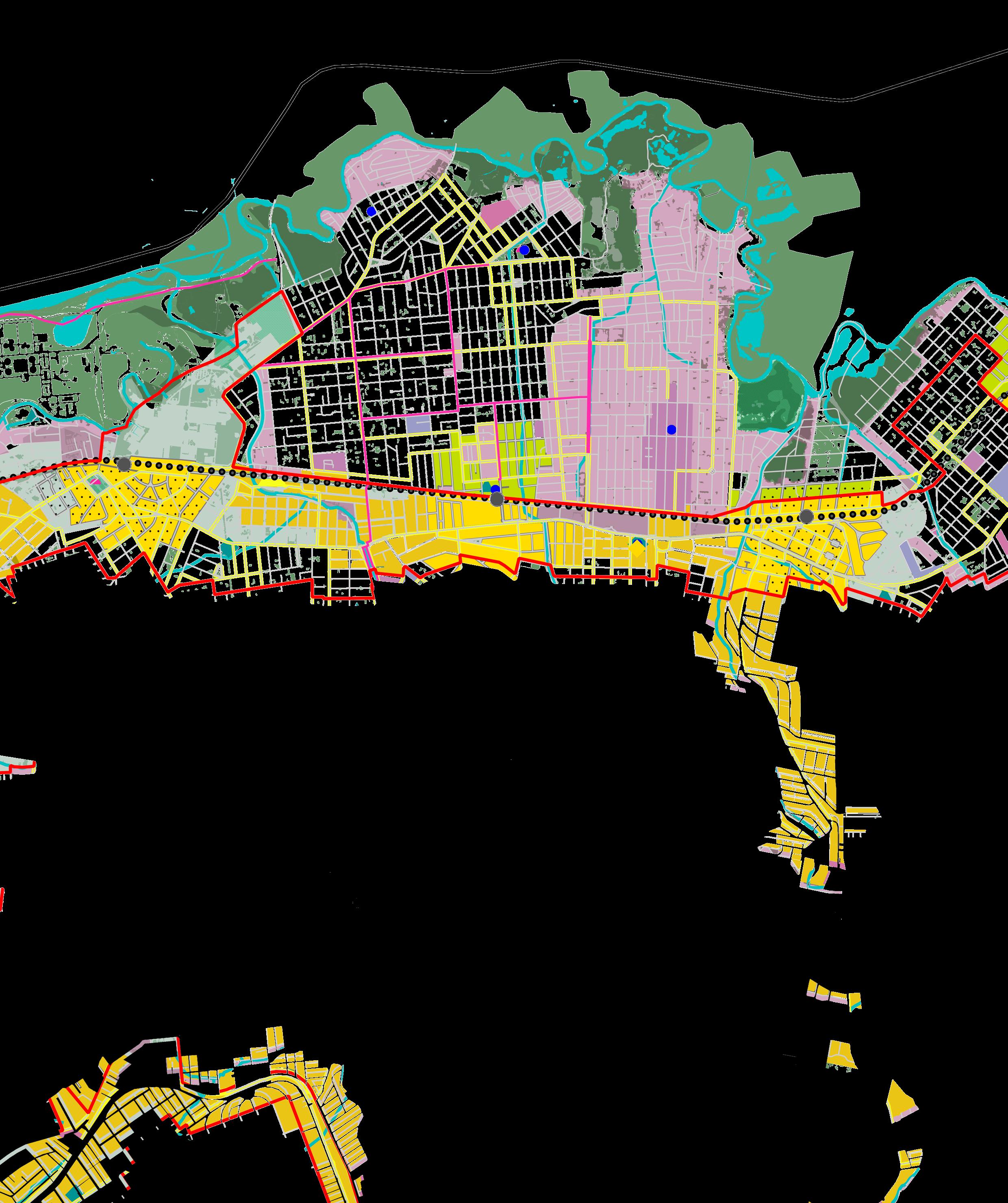
Based on the tangencies of the isochrones, points were marked at which the (temporal) distance between stations is equivalent. The next step was to trace the tangent lines and verify which area is uniquely provided by the
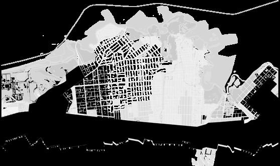
Tucuruvi station. Isochrones of 15 minutes and the tangend lines of the influent area of adjacents stations. Data: Geosampa, Google satellite. Analisys maps from bottom to top: (1) Natural resources, (2) Slope, (3) Number of travels made by metro on the origin and (4) Land use. Data: Geosampa, Google satellite. Study area delimited by the isochrone and the tangent line, determing the domain of Tucuruvi station. Data: Geosampa, Google satellite. TUCURUVIP. INGLESA JD. SÃO PAULO SANTANA
TUCURUVI P. INGLESA JD. SÃO PAULO SANTANA
In addition, relevant territorial analyzes were carried out in the studied area. It is mostly residential, with commerce and service hubs in regional centers.
The terrain has high slopes as it approaches a mountainous region, and its main roads develop in valleys or ridges.
PLANS
There is a large number of people who use the metro to travel to work centers in more central and distant regions.
Furthermore, it is possible to verify the existence of travels between nearby areas made by public transport. These fit into potential users for the active mode, if that is prioritized in the urban design process.
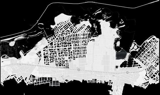
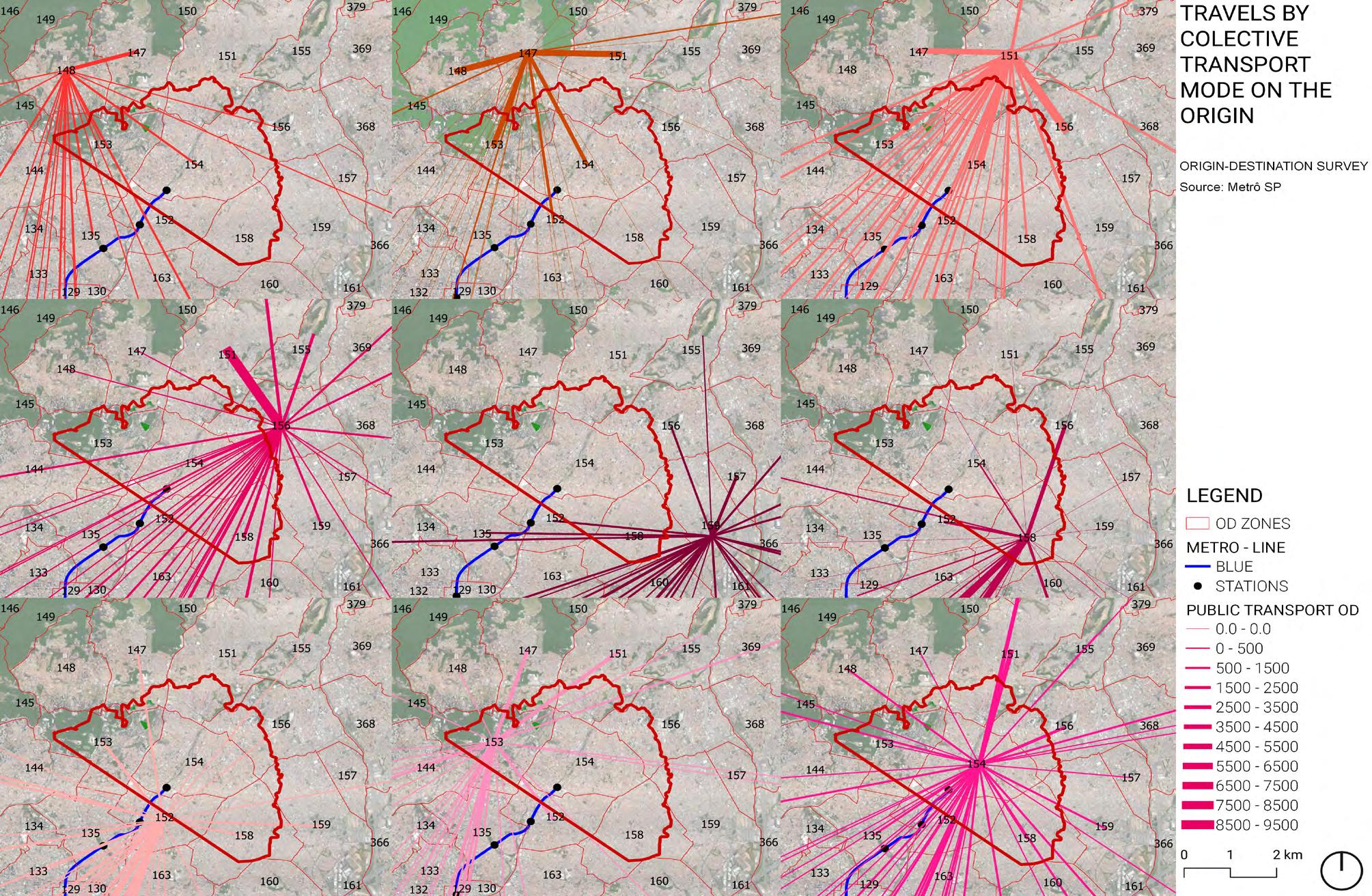 Number of travels made by public transport on the origin. Data: OD Survey - SP Metro, Google satellite.
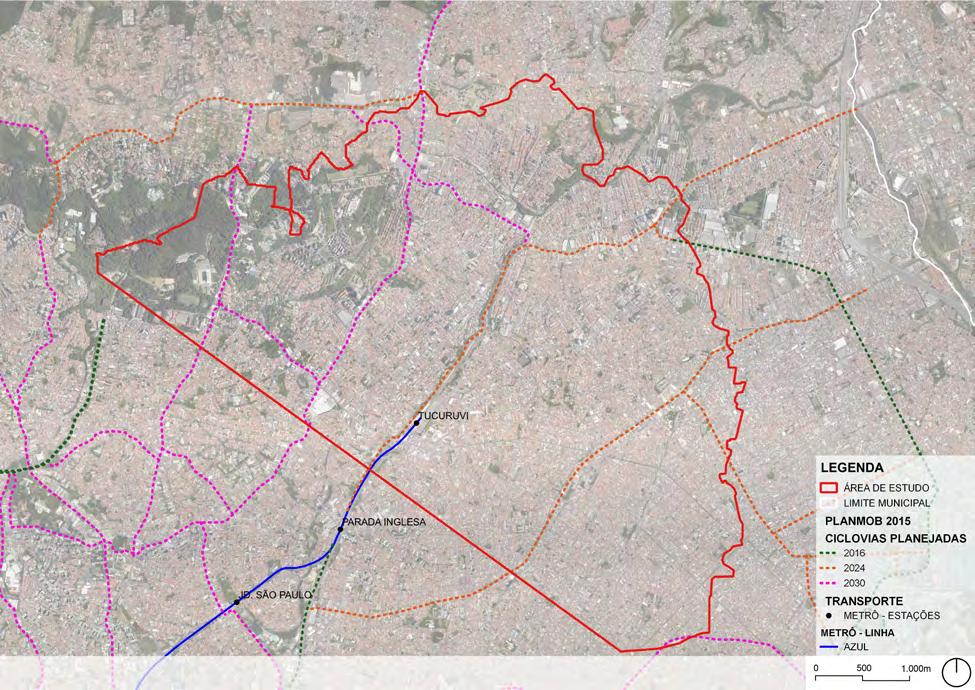
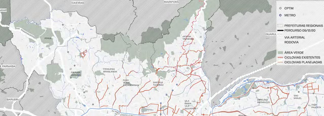
Cycle routes proposed on the City Mobility Plan (CMP) 2015. Data: CMP, Google satellite.
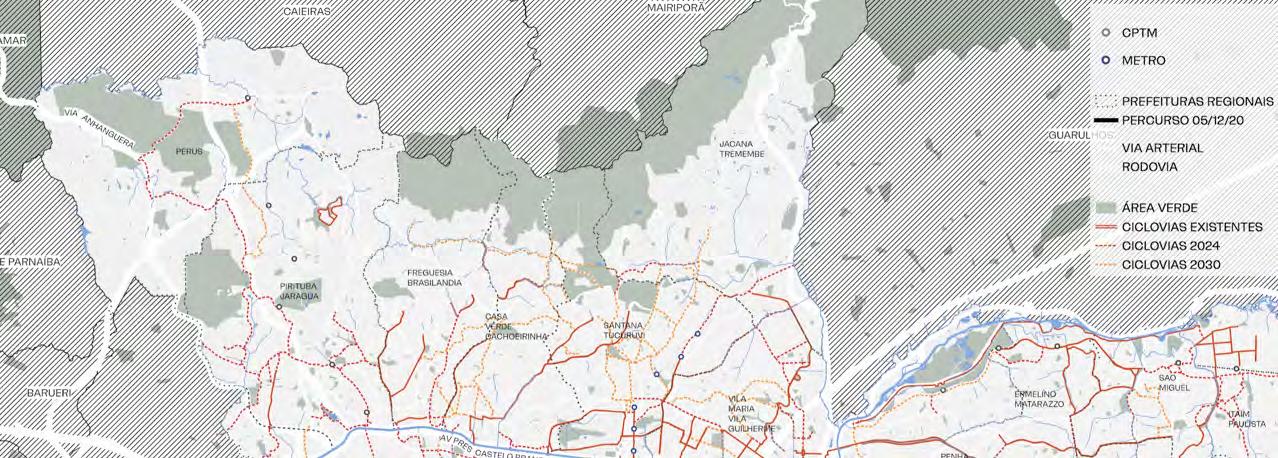
Cycle routes proposed on the City Cycle plan 2019. Data: City Cycle Plan, Google satellite.
Number of travels made by public transport on the origin. Data: OD Survey - SP Metro, Google satellite.
Cycle routes proposed on the City Mobility Plan (CMP) 2015. Data: CMP, Google satellite.
Cycle routes proposed on the City Cycle plan 2019. Data: City Cycle Plan, Google satellite.
CYCLE ROUTES OF INTEREST
The routes were traced taking into account the proposal of the previous plans. In order to generate a sample field capable of embracing unconventional or obvious routes, the demarcations were expanded, proposing a total of 15 routes with the potential to integrate a cohesive network for travel from or to the metro station.
ROUTE ANALYSIS
The routes were designed from points of origin-station/station-destination and vice-versa, and were conceived with the purpose of encompassing the most distant user. Some routes overlap, it means that different routes use the same cycleway structures.
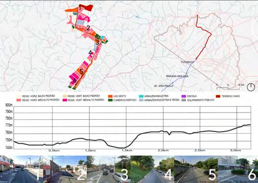
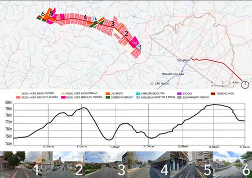
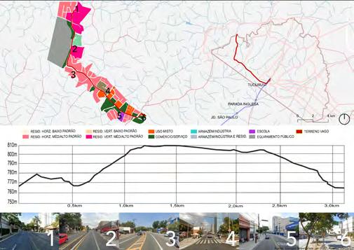
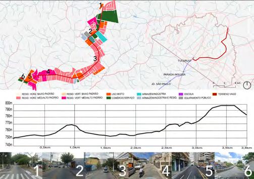
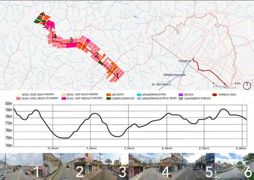
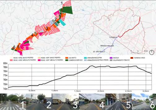
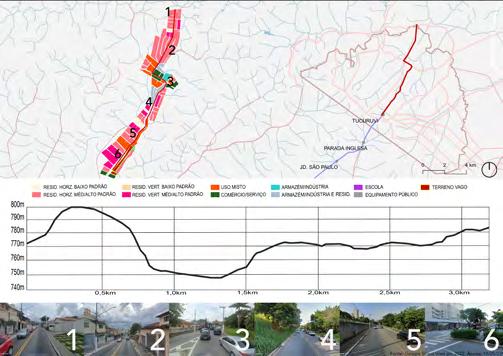
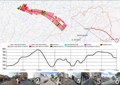
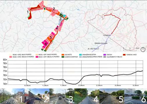
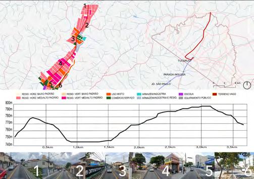
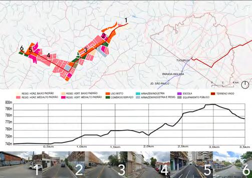
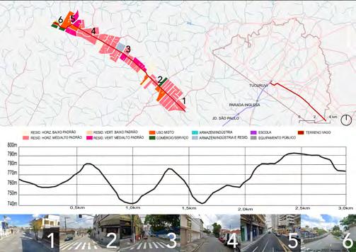
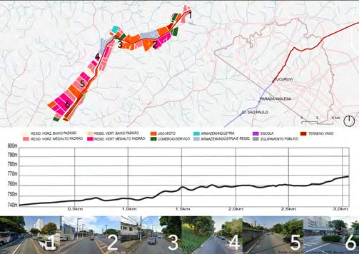
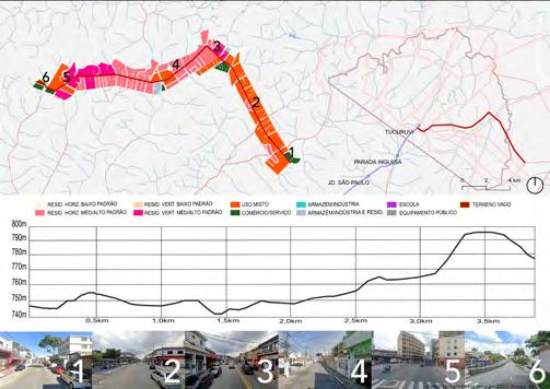
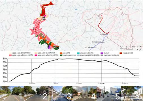
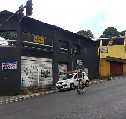
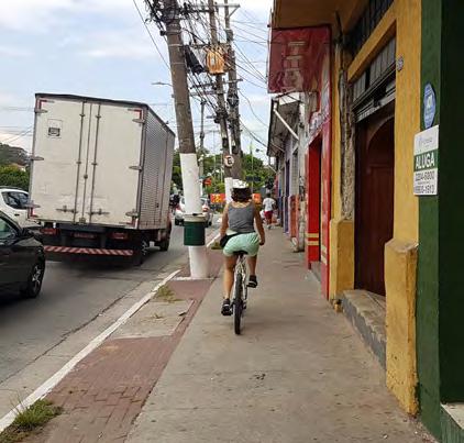
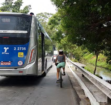
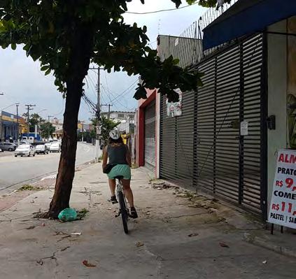
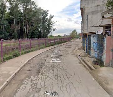
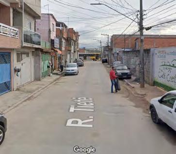
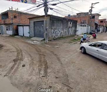
From the routes proposed, summary
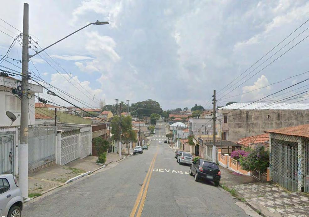
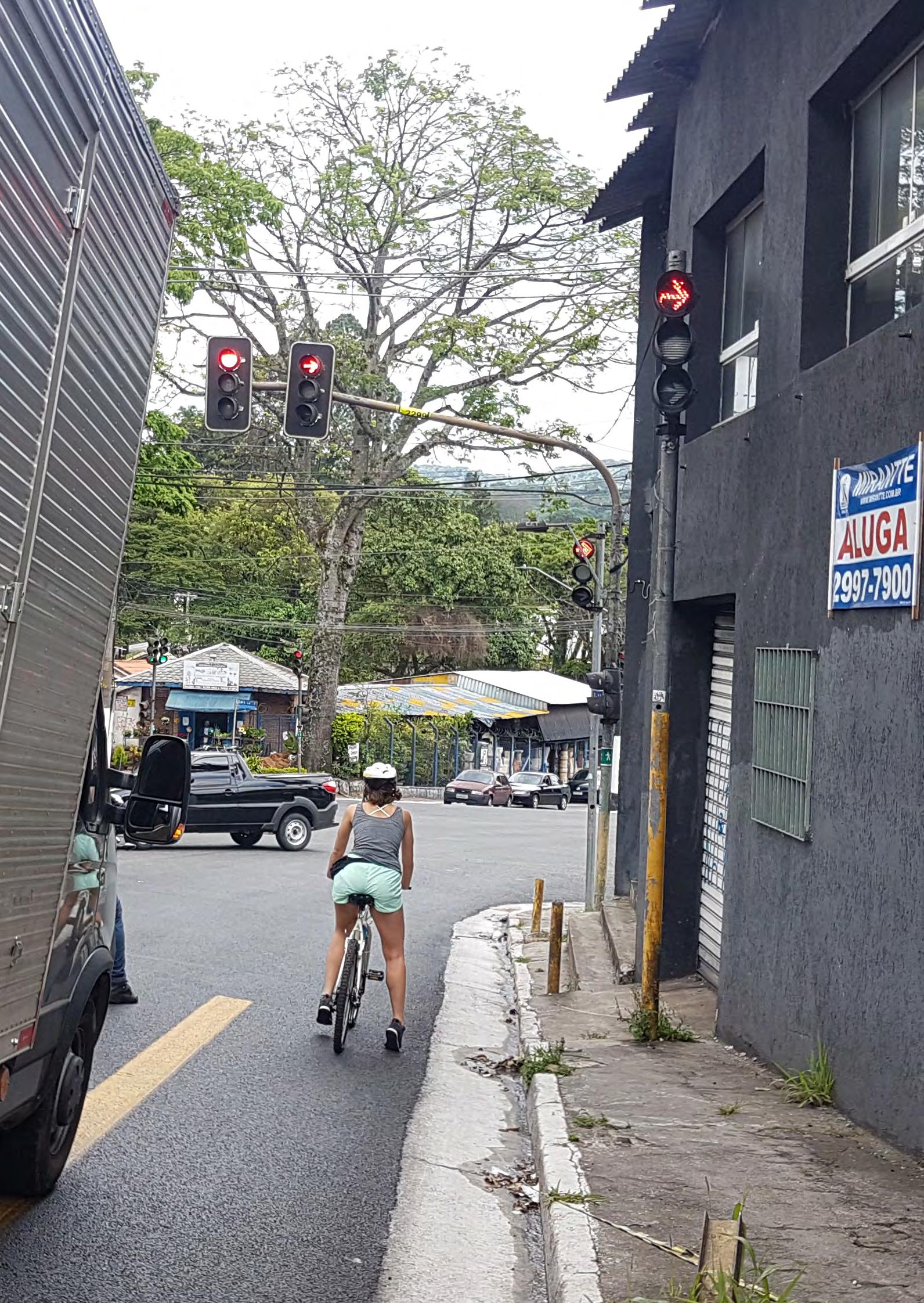
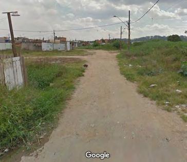
sheets were made, which bring information such as location, land use, elevation, and situation images. The images present the space and elucidate the sensation of the route, an essential variable for the choice of viable routes for the installation of a cycleway structure.
 Cycle routes proposed to the study. Data: Author, Google satellite.
Summary sheets of all 15 routes proposed. The sheets contain the location of the route in the study area, land use along the route, elevation and situation images. Data: Author, Geosampa.
Cycle routes proposed to the study. Data: Author, Google satellite.
Summary sheets of all 15 routes proposed. The sheets contain the location of the route in the study area, land use along the route, elevation and situation images. Data: Author, Geosampa.
For a closer study of the relationships on the ground floor, one of the proposed routes was chosen for the implementation of a cycleway structure and the study of possibilities.
Route 12 was chosen, as it has great potential for implementation, proves to be an important connection for the region, and has a large street and generous sidewalks, capable of absorbing the most different activities and variations of urban components.
From the choice of the route, 4 regions (quadrants) were defined with different design characteristics, uses, and densities, objecting to studying different relationships between lot, facade, and public space.
Police
ManuelGayaSt. AbílioPedroRamosSt.
FINAL PROPOSAL URBAN GROUND APPROXIMATION Metro Shopping Mall Bergamini Supermarkt Sambaiba São Luís Gonzaga Hospital Educational Center Jaçanã
Complex Horto Florestal Mandaqui Hospital
Luís Stamatis Ave.
ÁguaFriaAve. Eng. Caetano Álvares Ave.
NovaCantareiraAve. NovaCantareiraAve. QUAD. 01 QUAD. 02 QUAD. 03 QUAD. 04
Maria Amália Lopes
Azevedo Ave. Fernão Dias Rd. Dr.Antônio Maria LaetAv. Luiz Dumont Villares Ave. Júlio Buono Ave. GuapiraAve.
Cel.Sezefredo FagundesAve.
ROTA 12 METRO
ROUTE 12
Chosen route: Route 12. Satellite view and summary sheet. Data: Author, Geosampa, Google satellite.
Final proposed routes based on the analysis. The routes declined were considered uncomfortable, inefficient, and not use-propellant, mainly due to the topographic characteristics. Data: Author, Geosampa.
URBAN GROUND FLOOR ANALYSIS
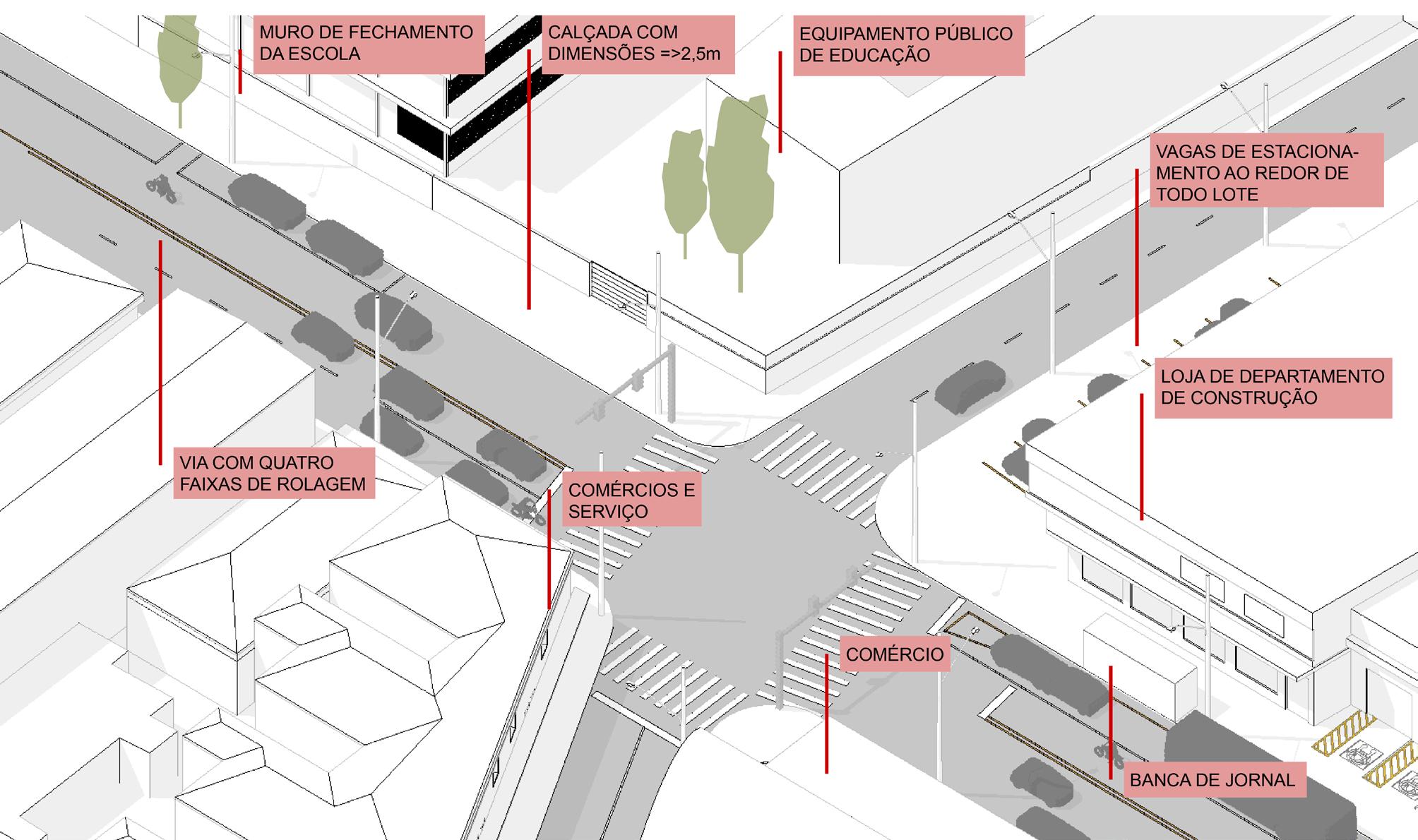
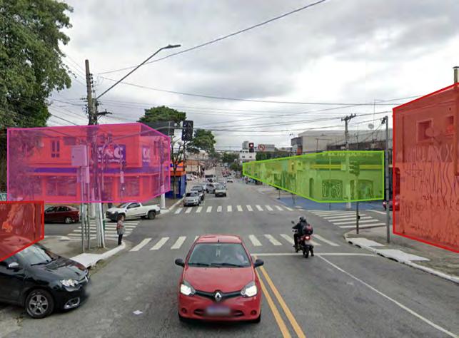
For the analysis of the existing ground floor, concepts developed by David Mangin were used, which focuses on understanding the relationship between private space and public space. In this way, analysis standards were established for the road, facade and the lot, as shown in the diagram as follow:
The analysis and proposal were made for the 4 chosen quadrants, and in each of them analyzed 3 different design contexts. For exemplification in this material, just one is presented.
QUADRANT 02
POROUS
HERMETIC POROUS IMPERMEABLE IMPERMEABLE PERMEABLE
STREET PERMANENCE PASSAGE FACADE
POROUS HERMETIC LOT PERMEABLE IMPERMEABLE
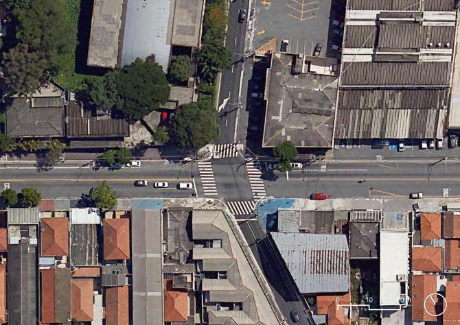
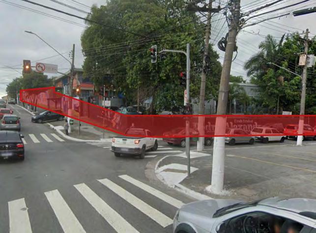
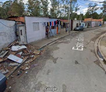
Urban Ground floor analysis, Intersection, Manuel Gaya Street. Data: Google Street View 2022
Comercial intersection, with a school on the top-left corner. Data: Google Satellite 2022
PASSAGE PASSAGE CLOSURE WALL SIDEWALK WIDTH > 2,5m COMMERCE AND SERVICE COMMERCE NEWSSTAND
PARKING LOTS
STORE
CONSTRUCTION DEPARTMENT
PUBLIC EDUCATIONAL EQUIPMENT
ROAD WITH FOUR DRIVE LANES
Quadrant 02 - actual situation analysis.
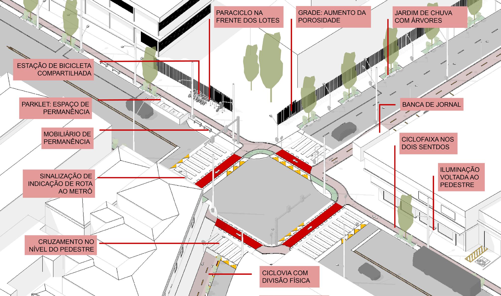
SHARED BIKE STATION
PARKLET: PERMANENCE SPACE
URBAN FURNITURE AND CORNER ENLARGEMENT
SIGNS DIRECTING THE METRO ACCESS
PARACYCLES DISTRIBUTION
FENCE: POROSITY ENHANCEMENT
RAIN GARDEN WITH TREES
CYCLE LANES IN BOTH WAYS
PEDESTRIAN STREET LIGHTING
SIDEWALK LEVEL CROSSING
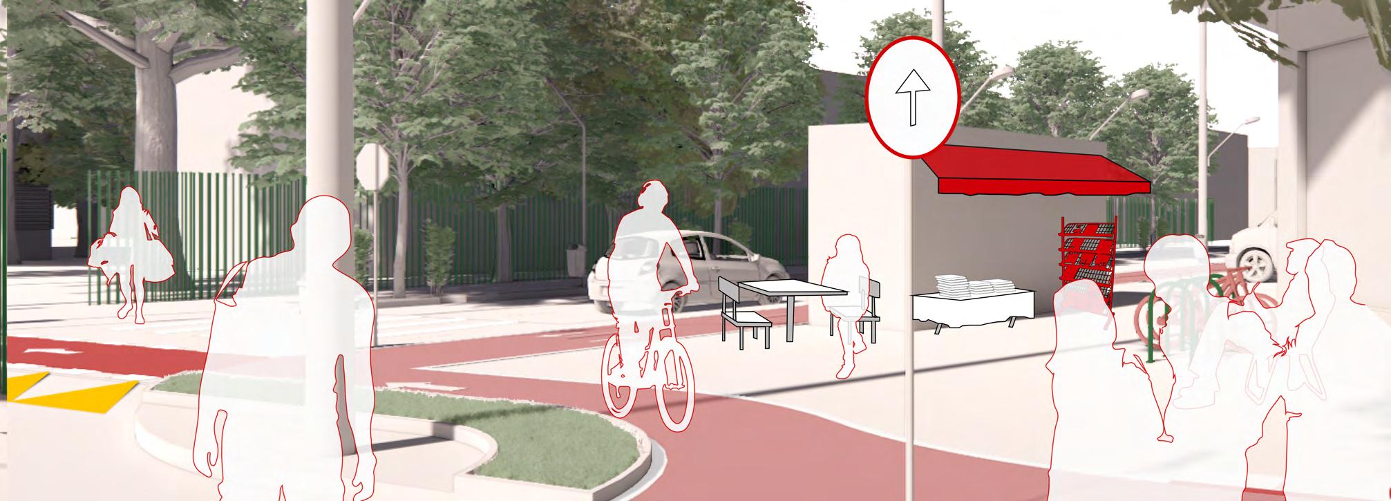
Quadrant 02, intervention proposal.
CYCLE LANES: DIVISORS WITH VISUAL QUALITY
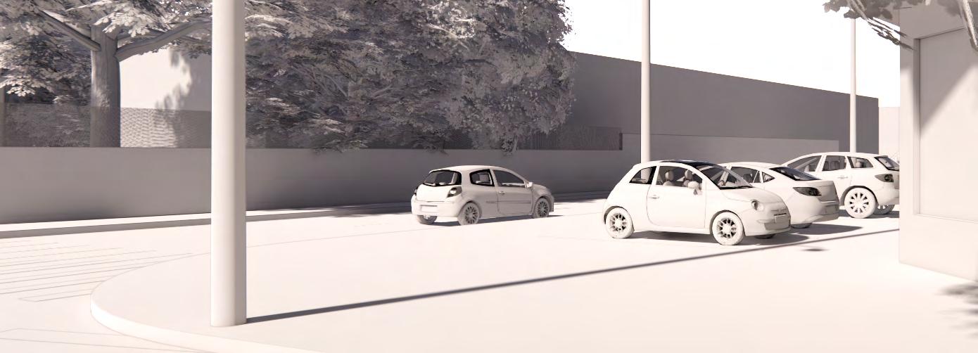
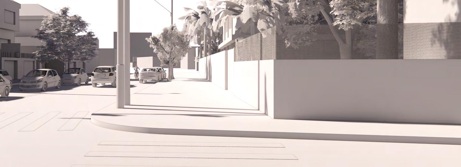
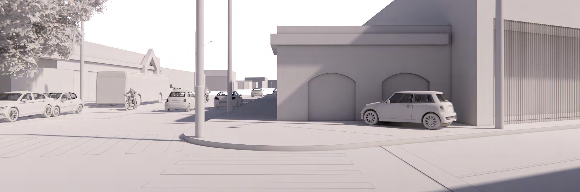
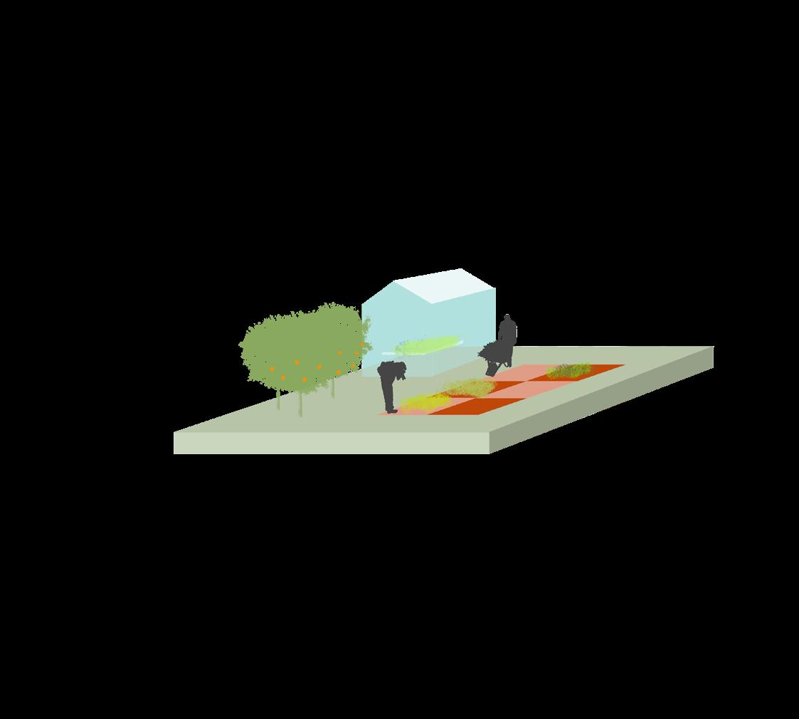
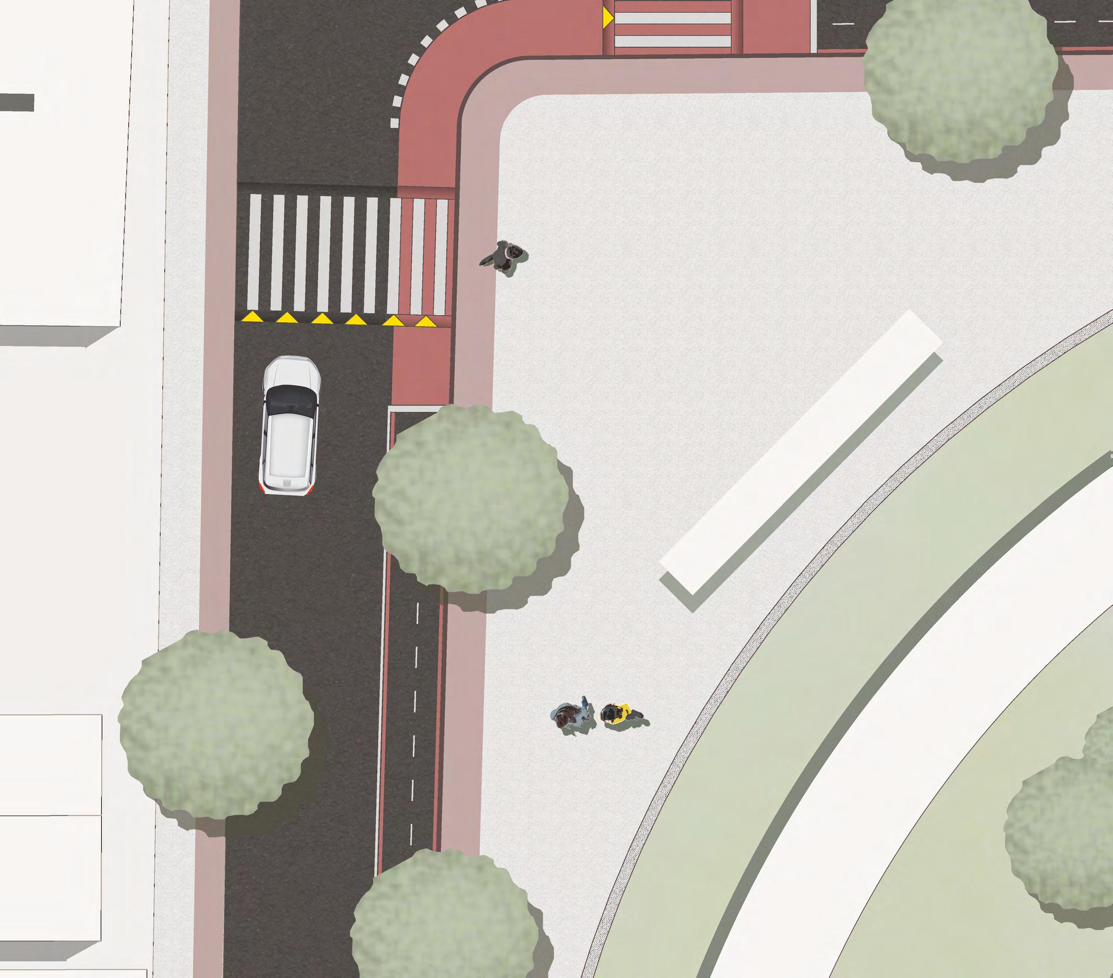
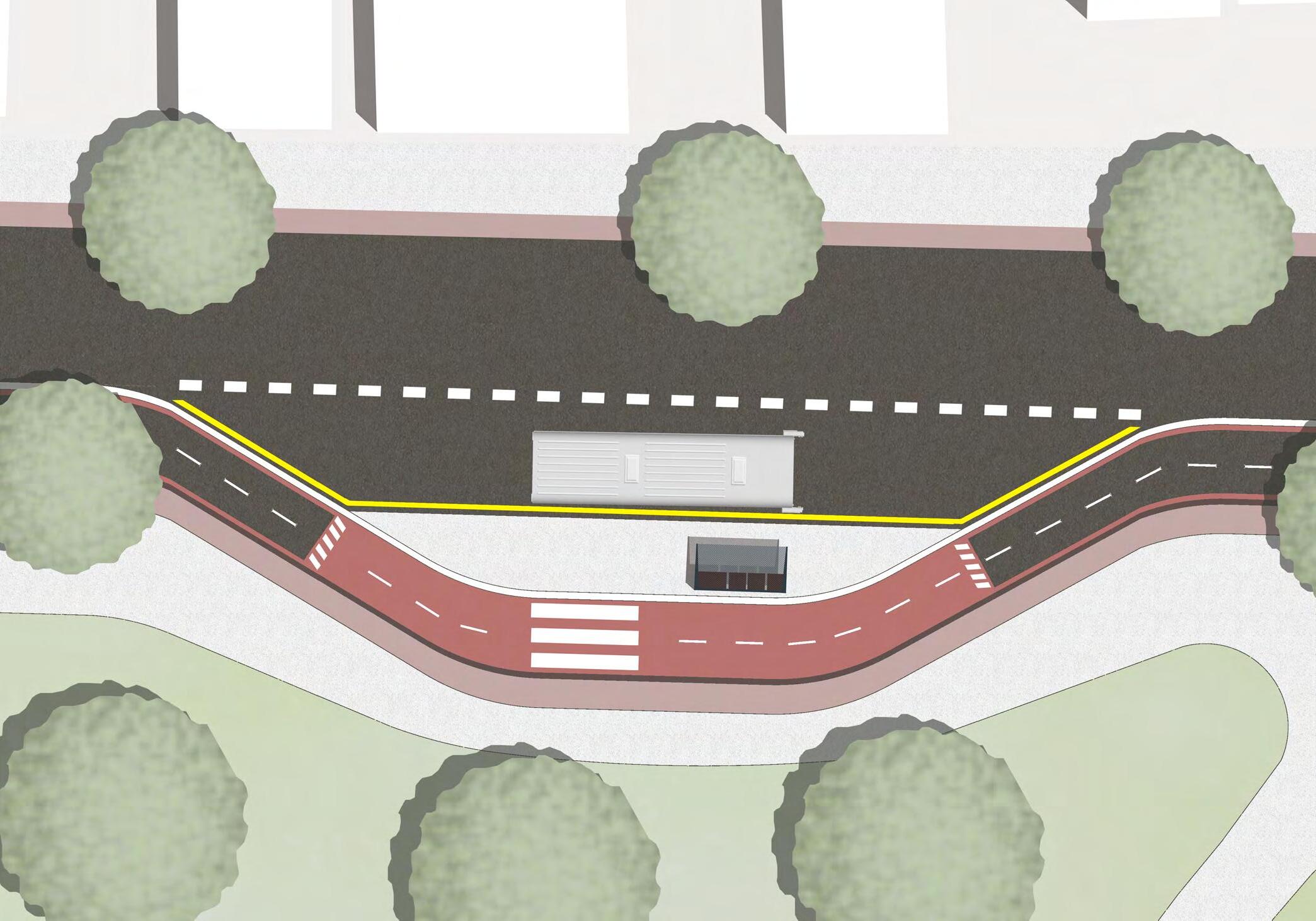
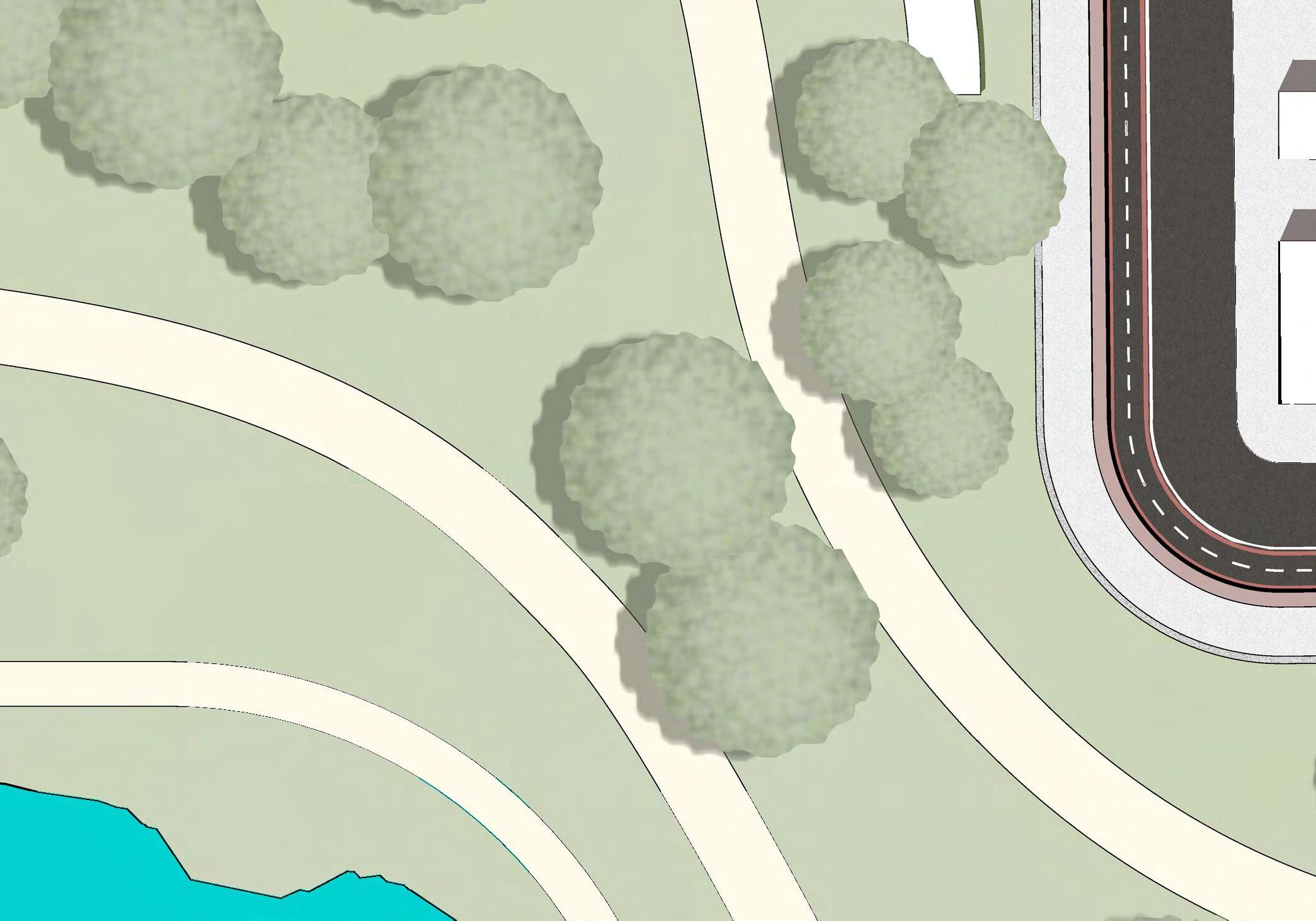
The proposal focuses on the ground floor aiming to make it safer at its intersections. It articulates the connection through active modes, seeking more coherence and spatial attractiveness. The use situations that could be flourished from the proposed interventions are presented below.
NEWSSTAND
Situation 01 - use possibilities - before and after.
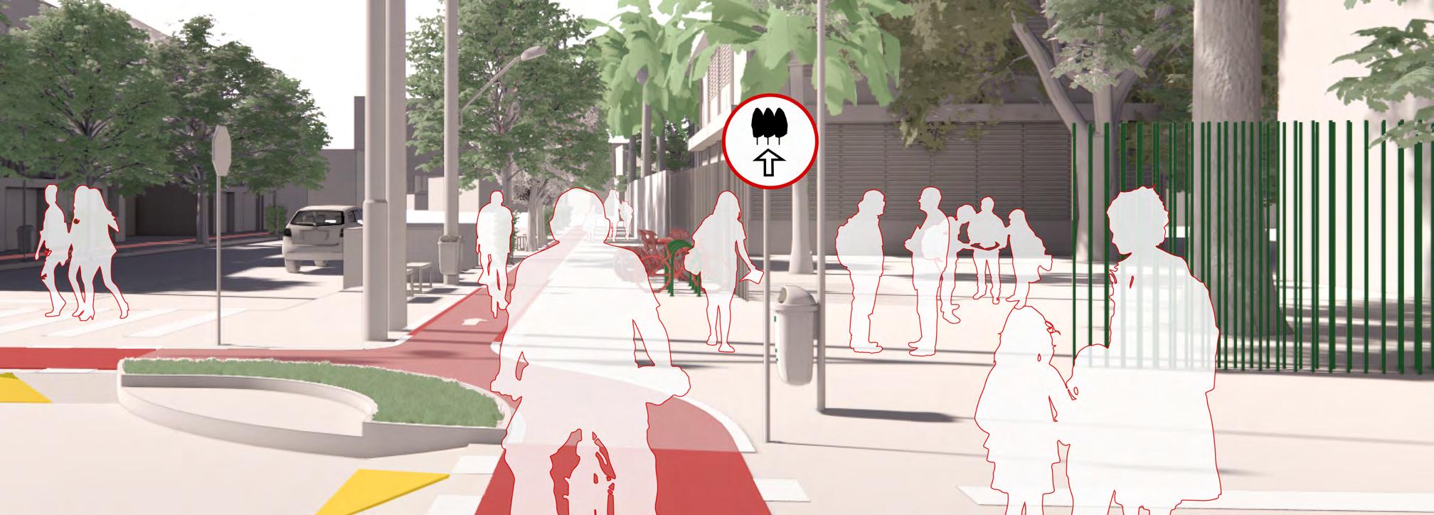
 Situation 03 - use possibilities - before and after.
Situation 02 - use possibilities - before and after.
Situation 03 - use possibilities - before and after.
Situation 02 - use possibilities - before and after.
LISTA DE PROJETOS
CYCLE INFRASTRUCTURE AND THE URBAN GROUND FLOOR
Synergy between high-capacity transport and active modes: implications on the urban ground floor
CYCLE PLAN STRATEGY: SÃO PAULO | Final Essay
CICLOMOBILIDADE | Jaçana - Tremembé
BRT CUIABÁ | 23 Sul
ESTUDO DE IMPLANTAÇÃO DE VLT | EGIS
SERPENTINA | The re-contact with nature
SPINE | Integrating housing in an industrial area
PARQUE DE VÁRZEA JD. HELENA | Recuperação da várzea do Tietê
PORTO FLUVIAL DE PASSAGEROS | Transição e transporte
CYCLE PLAN STRATEGY: SÃO PAULO
Final Essay
Unravelling the Cycling City 2020
The essay was developed in the Covid-19 Pandemic scenario and is the final product of the course Unravelling the Cycling City, hosted on Coursera by the University of Amsterdam.
The text discusses the Cycle Plan strategy of the City of São Paulo and relates it to the actual cycling structure.
For the full version visit: The Urban Cycling Institute page
“São Paulo has a lot to learn from cities where cycling is part of the daily basis of many, but adapting to the context of a super metropolis is necessary. The PDE appeals to the development of centralities to minimize the large trips made every day by workers. However, this dynamic is very solid and takes a long time to come into effect, so the bicycle network should be developed with greater focus locally to ensure accessibility for all city residents, even if it corresponds to only a portion of the daily commute. Thus, the use of bicycles is encouraged and transportation becomes more sustainable, improving the city’s quality and life.”
LISTA DE PROJETOS
CYCLE INFRASTRUCTURE AND THE URBAN GROUND FLOOR
Synergy between high-capacity transport and active modes: implications on the urban ground floor
CYCLE PLAN STRATEGY: SÃO PAULO | Final Essay
CICLOMOBILIDADE | Jaçana - Tremembé
BRT CUIABÁ | 23 Sul
ESTUDO DE IMPLANTAÇÃO DE VLT | EGIS
SERPENTINA | The re-contact with nature
SPINE | Integrating housing in an industrial area
PARQUE DE VÁRZEA JD. HELENA | Recuperação da várzea do Tietê
PORTO FLUVIAL DE PASSAGEROS | Transição e transporte
CICLOMOBILIDADE
J açana - Tremembé
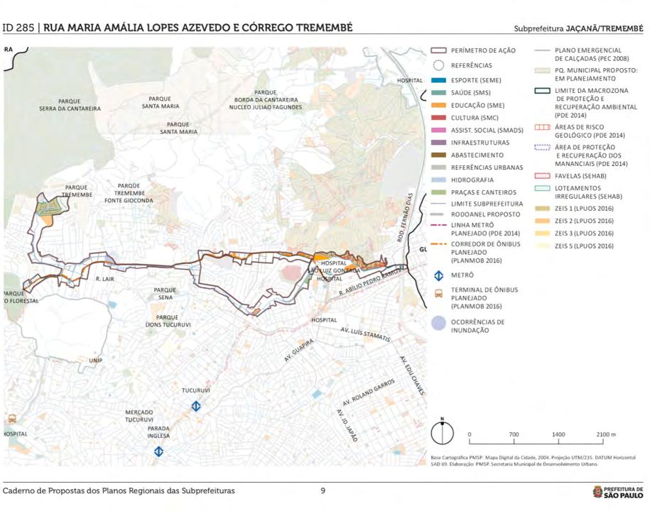
O trabalho foi desenvolvido dentro da disciplina “O sistema de espaços livres públicos urbanos: políticas, planos e projetos” da FAU-USP e tem como objetivo entender as ferramentas legislativos e as políticas que englobam a infraestrutura cicloviária na cidade de São Paulo, mais especificamente na região Norte, com especial atenção as ligações com equipamentos urbanos e nós de transporte.
O trabalho avalia rotas existente destinadas à bicicleta em contraponto aos trajetos desejados pelos usuários, além dos desafios físicos e morfológicos enfrentados para consolidação da bicicleta como meio de transporte.
Ainda, é feito uma consulta pública, buscando entender as impressões e opiniões a respeito da implantação de uma nova ciclofaixa na região.
Cheque a trabalho completo no link: Ciclomobilidade na Prefeitural Regional Jaçana-Tremembé
O sistema de espaços livres públicos urbanos: políticas, planos e projetos Docente: Fábio Mariz
L ocal: Jaçana - Tremembé, São Paulo - SP Brasil 2020
Barbara Sula Braga Luisa Lemes Martim FerrazPLANOS REGIONAIS
PLANOS, DIRETRIZES E PROJETOS
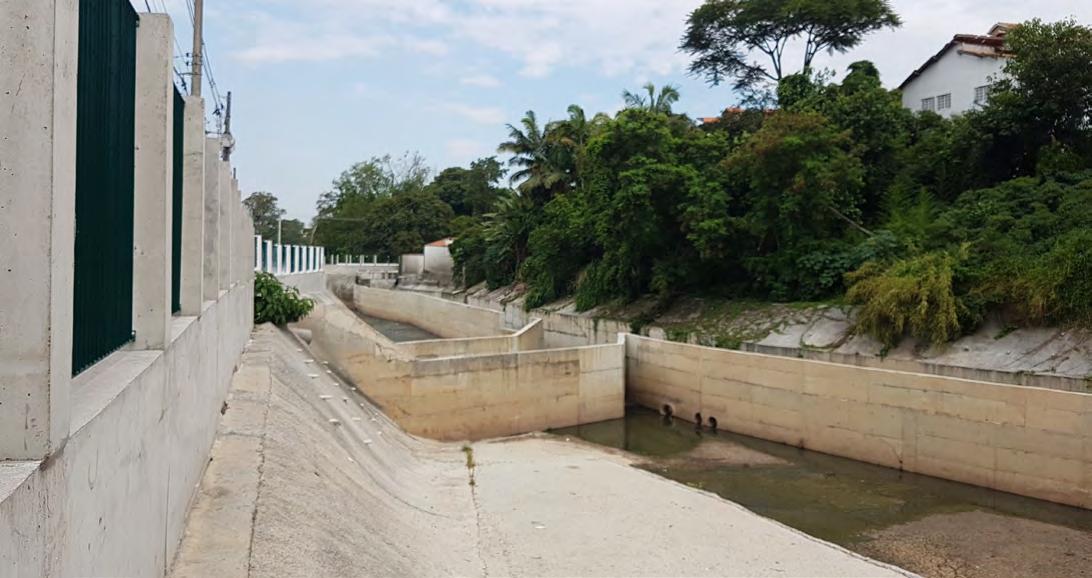
Piscinão R3, próximo a rua Comendador Quirino Teixeira (córrego Tremembé) - capacidade: 18 mil m³, Contrato: 008/SIURB/2015. Foto: Martim Ferraz
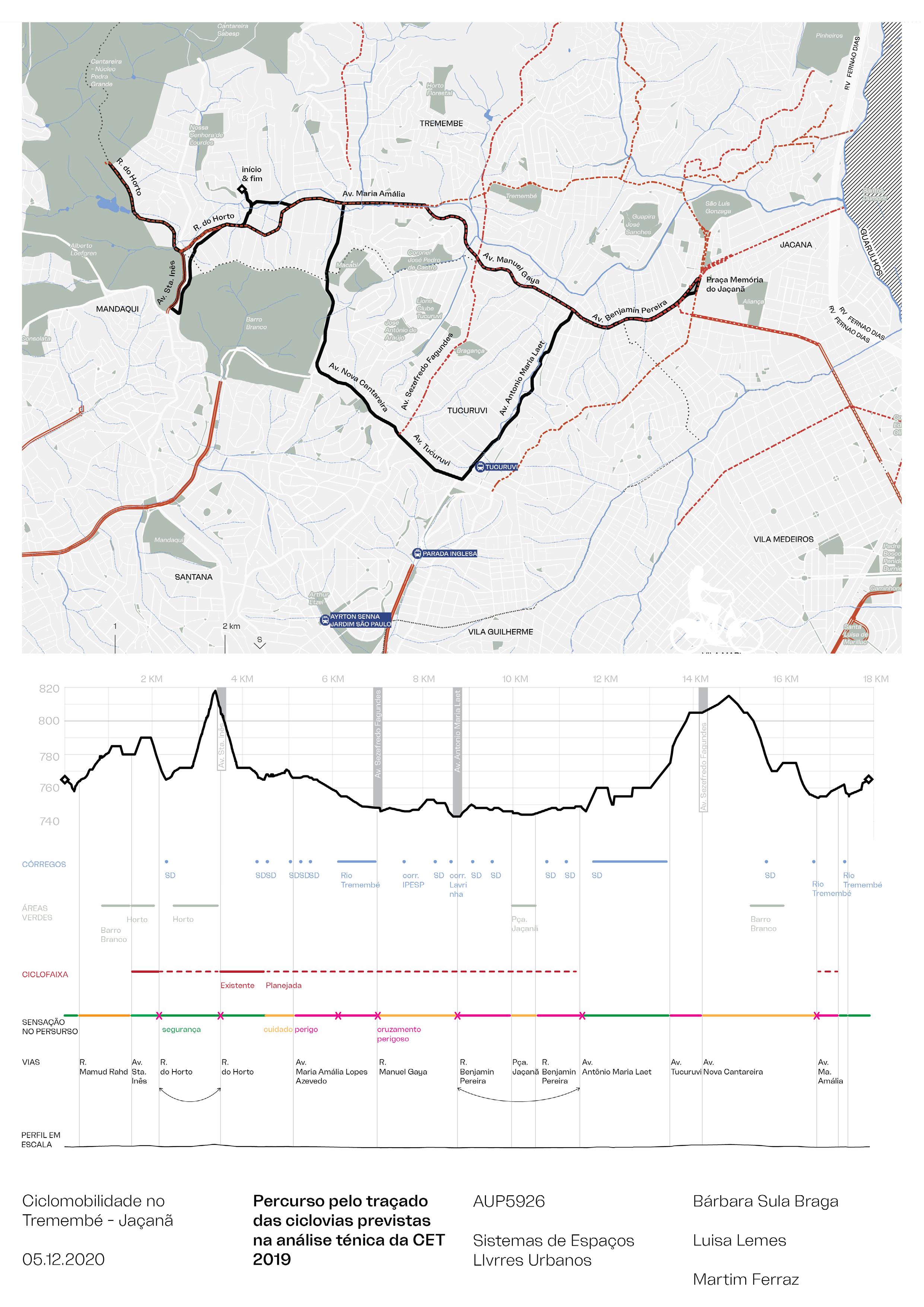
ANÁLISE TÉCNICA DA CET
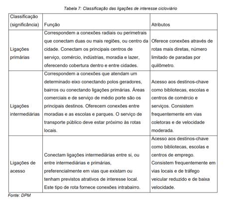
De acordo com o caderno da CET a metodologia usada para a estruturação da rede cicloviária é retirada da Classificação das ligações de interesse cicloviário, elaborada pelo Departamento de Transportes de Minnesota – MN/DOT (2007), no Manual de Projetos de Rotas Cicláveis. Na Subprefeitura do Jaçanã/Tremembé foi identificada a viabilidade de implantação de estrutura cicloviária na Rua Manuel Gaya, Rua. Benjamim Pereira, Rua Carlos Bastos Aranha, R. Abílio Pedro Ramos e Av. Luís Stamatis (trecho entre Av. Guapira e Rua Benjamin Pereira). Vale lembrar que, excetuando-se a Av. Luís Stamatis, as vias acima apontadas formam um eixo em houve grande número de acidentes envolvendo ciclistas vítimas.
Parques lineares são infraestruturas importantes para gerar cidades mais aprazíveis e sustentáveis, no entanto políticas continuam com seu caráter individual e não integram diferentes setores na construção do meio urbano.
Na imagem observa-se a construção de piscinões para conter os alagamentos na região do Tremembé, sem qualquer cuidado com os sistemas adjacentes, solucionando um problema, mas criando outro no aspecto da paisagem urbana e relação humana com o meio.
“[...]atendendo aos objetivos previstos, sobretudo o da ampliação da percepção do cidadão sobre os elementos do meio físico, os parques lineares devem ser contemplados com infraestruturas necessárias para a mobilidade por bicicletas, em especial aqueles que têm potencial para permitir ligações locais entre bairros e novas conexões com a Rede Cicloviária Estrutural.”
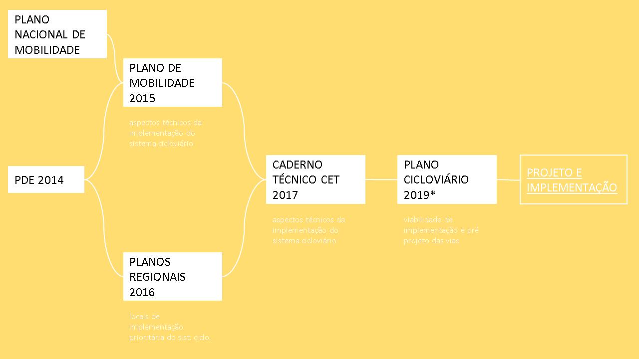
PLANO DE MOBILIDADE 2015
PLANO DE MOBILIDADE 2015 - PLANMOB
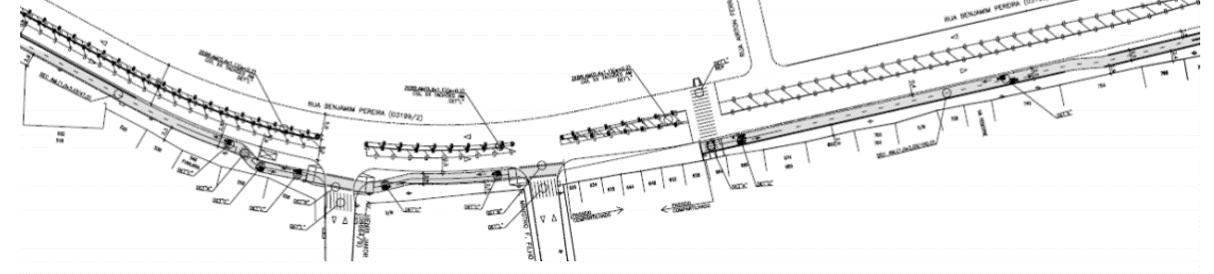
Conexão planejada, Funcional em trecho da Rua Abílio Pedro Ramos; Mapa retirado do caderno de análise técnica da CET para a Subprefeitura do Jaçanã-Tremembé. Fonte DPM
dados: ciclocidade geosampa
ANÁLISE TÉCNICA DE CET 2017
dados: CET geosampa
PLANO CICLOVIÁRIO 2019
dados: ciclocidade geosampa
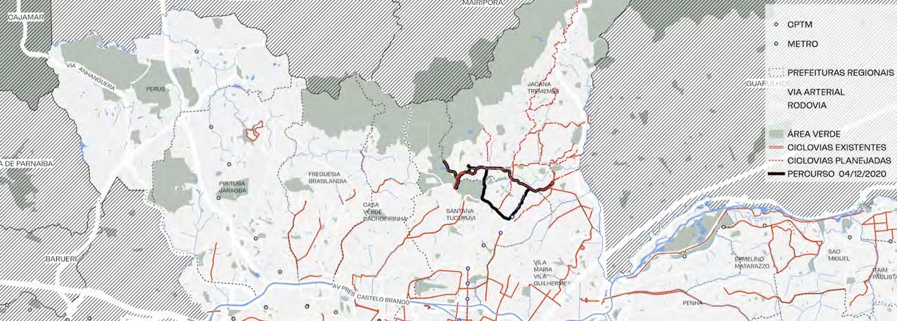
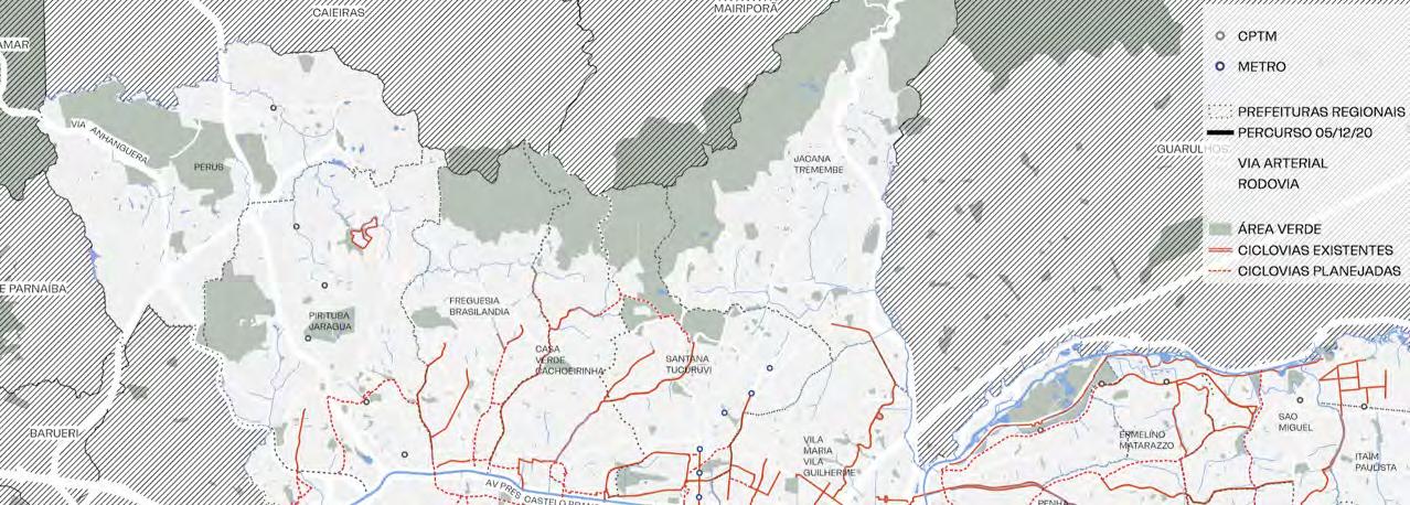
PERCURSO REALIZADO DE BICICLETA 12/2020
dados: CET geosampa
PLANO DE MOBILIDADE 2015
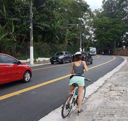
Imagens do percurso. Martim Ferraz
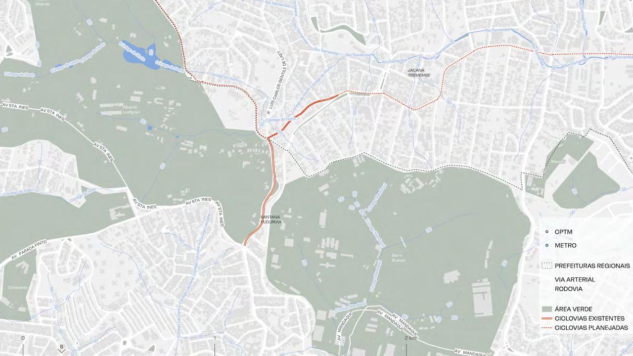
1170 m
implementada no início de Novembro, 2020
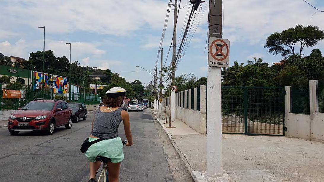
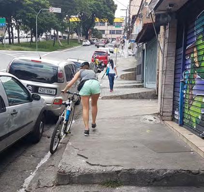
A ciclovia foi implementada na Rua do Horto e Av. Luis Carlos Gentile de Laet, que liga a primeira a Av. Santa Inês, umas das principais conexões Leste-Oeste, que conecta Guarulhos a região do Mandaqui. Neste ponto de implementação, encontra-se o Parque Estadual Alberto Löfgren, ou Horto Florestal de São Paulo, entretanto observa-se que a ciclovia não conectou ne-
nhuma entrada do parque, mesmo a conexão sendo fácil e desejada.
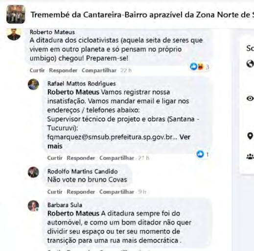
A partir desse cenário, e a falta de conexão cicloviária com pontos importantes ou com a rede cicloviária existe na Av. Engenheiro Caetano Álvares, pouco a frente, a ciclovia gerou grande repercussão negativa entre os moradores do bairro.

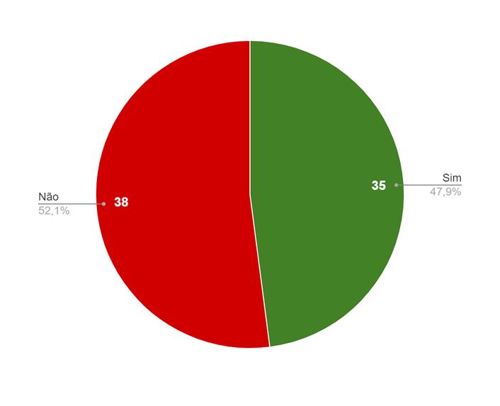
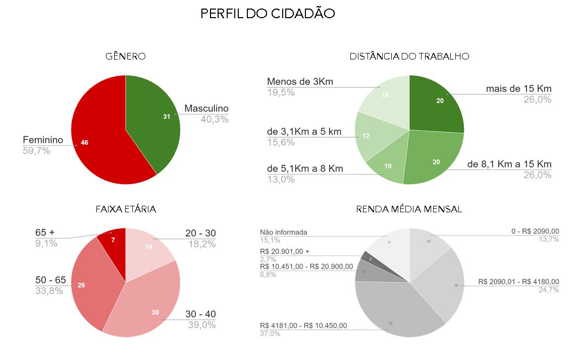
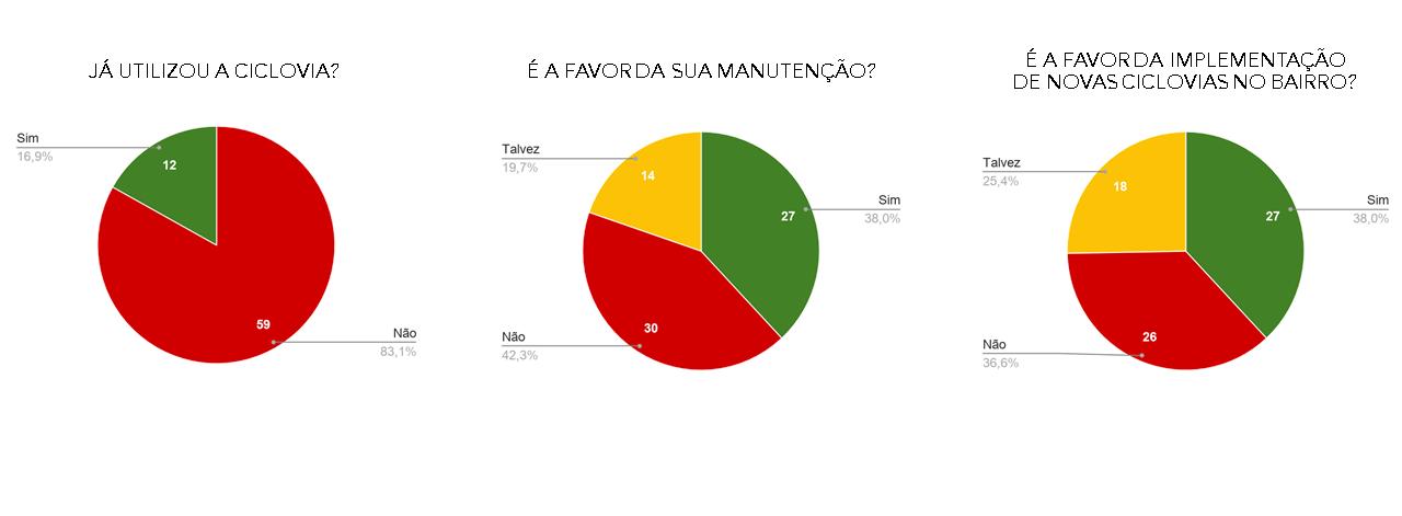
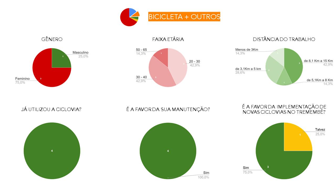
Foi realizado um questionário online com os moradores para entender suas impressões e opiniões.
PARA ACESSAR O QUESTIONÁRIOS E AS PERGUNTAS REALIZADAS, ACESSE O LINK: CICLOMOBILIDADE
NOVA CICLOFAIXA
NO TREMEMBÉ
MUDANÇAS DE MEIO DE TRANSPORTE DEVIDO À PANDEMIA
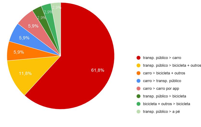
TOTAL POR TIPO DE TRANSPORTE
RESULTADOS E CONCLUSÕES
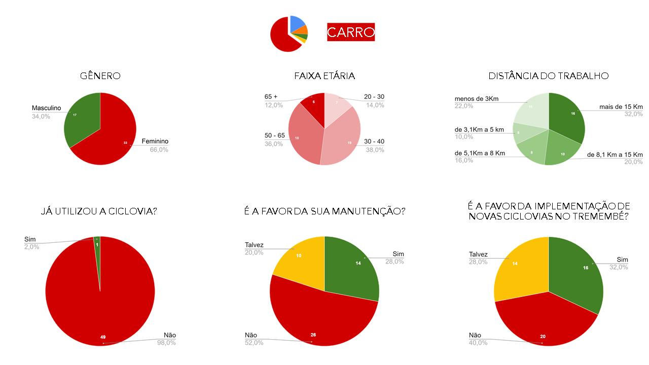
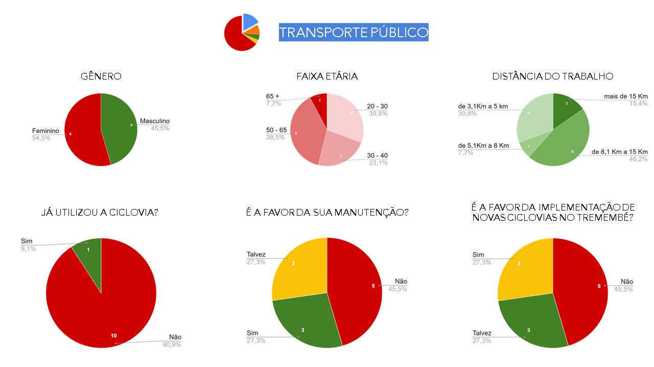
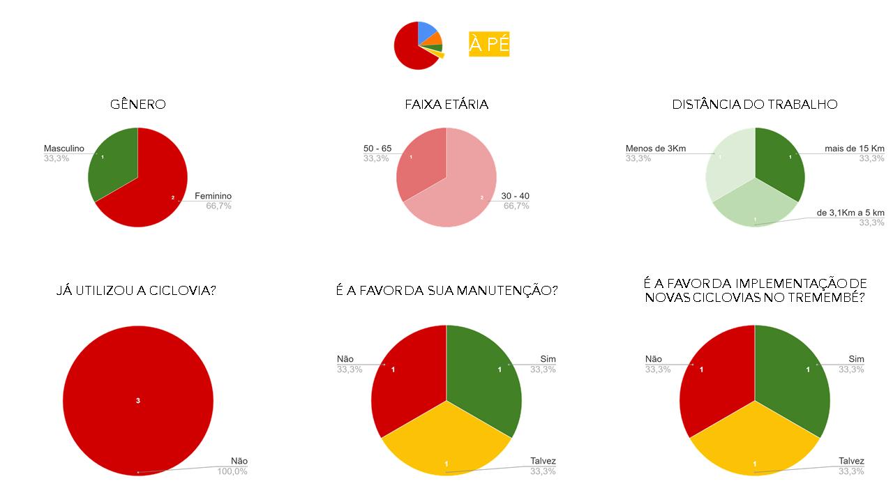
Observa-se que a maioria dos que responderam ao questionário não utilizaram a ciclovia. Com isso percebemos que as respostas obtidas não refletiram em sua maioria a opinião de ciclistas e não necessariamente representam a opinião das pessoas sobre a ciclofaixa em si, mas sim dela em relação aos meios de transporte que não a bicicleta. Ao explorar as explicações dadas às respostas dos dois últimos gráficos, verifica-se que grande parte
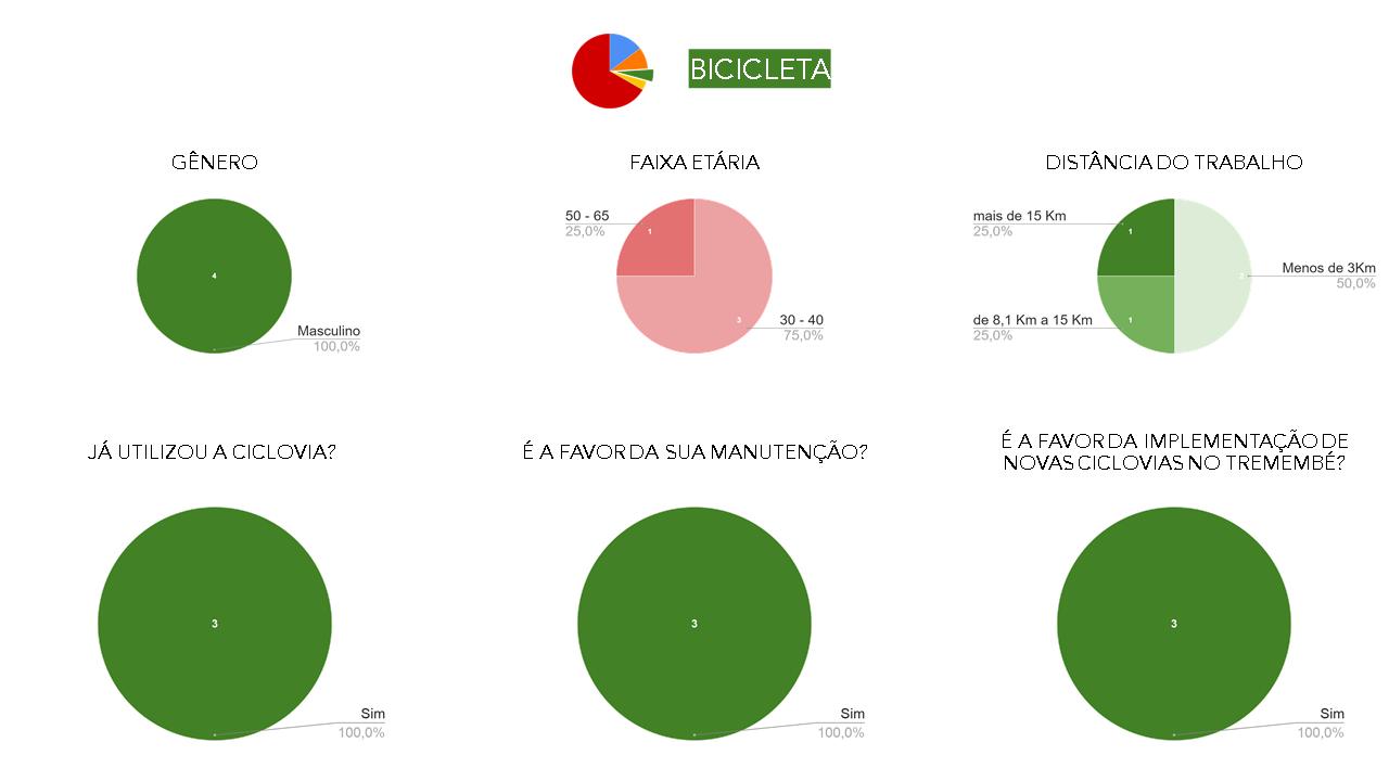
das pessoas não é contra ciclofaixas no Tremembé no geral, mas sim contra a ciclofaixa implementada recentemente, pois julgaram que sua localização não foi devidamente pensada. Essas pessoas acreditam que a via escolhida possui grande fluxo de carros e é muito estreita para receber tal equipamento. Porém, elas são a favor de sua implementação em vias com melhores condições.
LISTA DE PROJETOS
CYCLE INFRASTRUCTURE AND THE URBAN GROUND FLOOR
Synergy between high-capacity transport and active modes: implications on the urban ground floor
CYCLE PLAN STRATEGY: SÃO PAULO | Final Essay
CICLOMOBILIDADE | Jaçana - Tremembé
BRT CUIABÁ | 23 Sul
ESTUDO DE IMPLANTAÇÃO DE VLT | EGIS
SERPENTINA | The re-contact with nature
SPINE | Integrating housing in an industrial area
PARQUE DE VÁRZEA JD. HELENA | Recuperação da várzea do Tietê
PORTO FLUVIAL DE PASSAGEROS | Transição e transporte
BRT CUIABÁ
Anteprojeto para implantação do sistema de ônibus de trânsito rápido (BRT: Bus rapid transport) em Cuiabá
Local: Cuiabá - Mato Grosso
Brasil
A proposta de implantação do BRT surgiu a partir de um estudo encomendado pelo Governos Estadual de Mato Grosso, após o projeto de implantação de VLT para a Copa do Mundo de 2014, atrasado, ser cancelado em 2017 por denúncias de corrupção.
Assim, com base em pareceres técnicos realizados, a Engenharia de Valor demonstrou a possibilidade de otimização da solução BRT, abrangendo o traçado original proposto para o VLT. Desta maneira, foi prevista a potencialização dos
Projeto: 23 Sul Arquitetura e Urbanismo
ganhos de eficiência para a prestação do serviço e uma significativa redução de custos iniciais de implantação, bem como de custos totais ao longo da vida útil do empreendimento.
O novo trajeto é apresentado a seguir e a partir dele foram desenvolvidos projetos de estações, terminais, parque e praças; melhorias de traçados geométricos e qualificação urbana do entorno da linha do BRT, de forma a preparar a região ao crescimento e modificação de uso que as vias tendem a sofrer com a implantação do sistema.
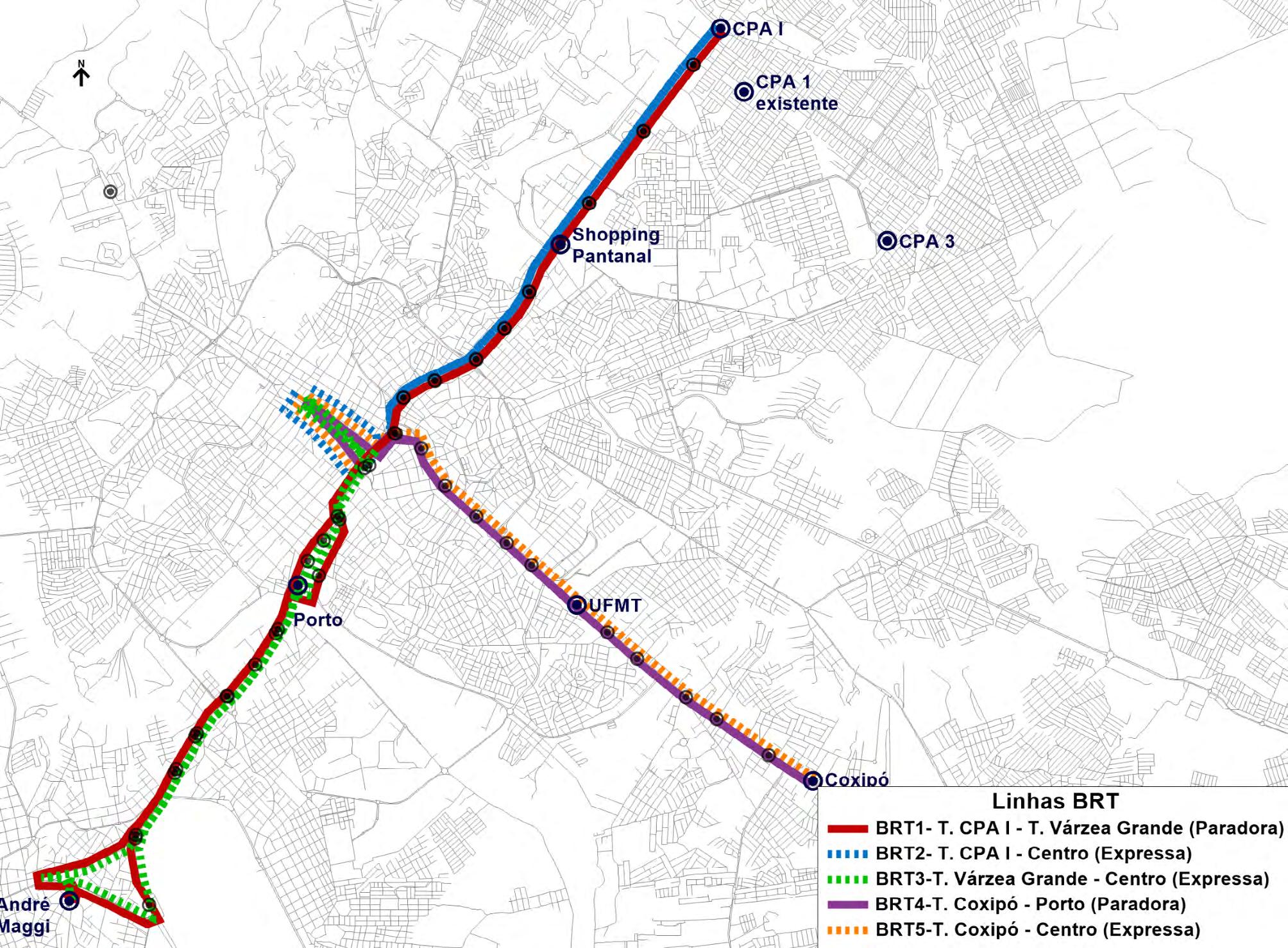
IMPLANTAÇÃO | Percursos das linhas do BRT.
O BRT Contará com 5 linhas, das quais duas são linhas paradoras: Cuiabá (Novo CPA I) – Várzea Grande (André Maggi) e Cuiabá (Coxipó) – Cuiabá (Centro), e 3 linhas expressas nos horários de pico, que são: Cuiabá (Novo CPA I) – Cuiabá (Centro), Cuiabá (Coxipó) – Cuiabá (Centro) e Várzea Grande (André Maggi) – Cuiabá (Centro). Todas as linhas operarão com veículos superarticulados (considerar 23m).
2021
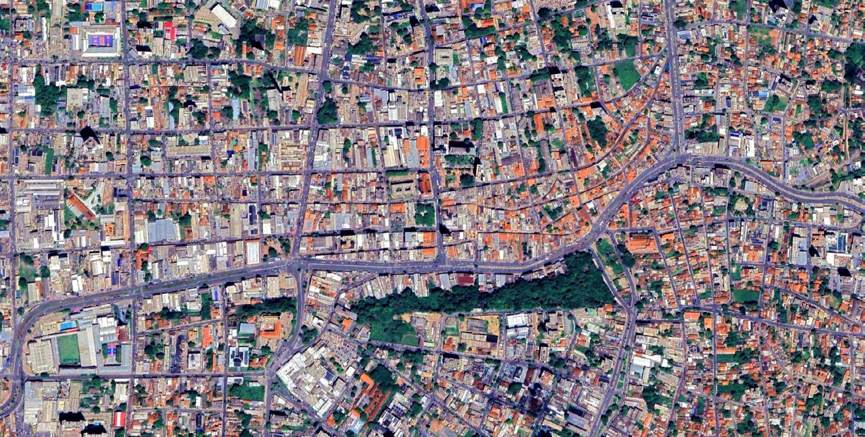
O desenvolvimento do trabalho focou no estudo de geometria e de melhorias urbanas na região denominada Prainha, região central da cdade, delimitada ao sul pela Avenida Dom Bosco e ao norte pela Avenida Mato Grosso.
Este trecho do projeto conta com três estações de embarque e desembarque. Estas foram dispostas a uma distância aproximada de 1600 metros de distância uma da outra, de acordo com a viabilidade.
Para implantação da linha de BRT, foram necessários ajustes de geometria da via existente, de forma a receber a linha em ambos os senti-
dos e os alargamentos das estações.
Ainda, neste trecho foi proposto o alargamento das calçadas de forma a receber todo o público da área central. Nestas foram previstos jardins de chuva, que cooperam para a drenagem urbana de forma amigável à paisagem, além de rampas e piso tátil para acessibilidade universal, mobiliário urbano e iluminação pública.
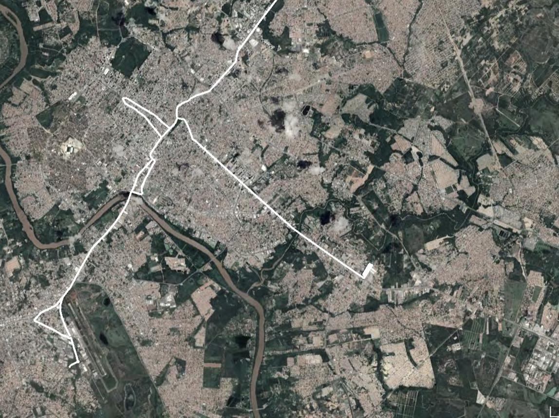
IMPLANTAÇÃO | Região da Prainha. Fonte Google Earth 2023.400m 0
Sem escala. Fonte Google Earth 2023
PRAINHA| Projeto geométrico e de qualificação urbana. Sem escala.
Estação BRT
Para os estudos foram feitas 15 ampliações do trecho, as quais 5 são apresentadas aqui
PLANTA DE IMPLANTAÇÃO | Quadra leste 1 e Quadra oeste 1 | Estacas de 397,00 a 402,00 (Eixo CPA Leste)..
PLANTA DE IMPLANTAÇÃO | Quadra leste 1 e 2 e Quadra oeste 1 | Estacas de 391,00 a 397,00 (Eixo CPA Leste).
PLANTA DE IMPLANTAÇÃO | Quadra leste 3 | Estacas de 382,00 a 387,00 (Eixo CPA Leste).
PLANTA | Ampliação Quadra Leste 5.
PLANTA | Ampliação Quadra Leste 7 e 8.
LEGENDA
LEGENDA:
COTA DE NÍVEL (ACABADO)
PISO DE CONCRETO MOLDADO IN LOCO DESEMPENADO, PIGMENTADO EM TONALIDADE CINZA ESCURO
PISO DE CONCRETO MOLDADO IN LOCO DESEMPENADO
PAVIMENTO INTERTRAVADO RETANGULAR GRAFITE 20x10cm
PISO TÁTIL DIRECIONAL
PISO TÁTIL ALERTA
REBAIXAMENTO DE CALÇADA PARA PEDESTRES
MEIO-FIO EXISTENTE
NOTAS:
ÁRVORE EXISTENTE
ÁRVORE ELIMINADA
ÁRVORE PROPOSTA
COBERTURA VEGETAL, CONSÓRCIO DE SEMENTES
BRITA GRADUADA SIMPLES
ARGILA COMPACTADA
De forma a sistematizar o projeto proposto para as calçadas da Prainha, foram desenvolvidos componentes urbanos. Os componentes podem ser elementos com dimensões fixas, como os mobiliários urbanos - lixeiras e bancos - e os postes de iluminação, ou elementos variáveis, como os jardins de chuva, que adaptam sua largura e comprimento de acordo com cada situação de cada quadra viária.
A faixa livre de circulação da calçada permaneceu com largura constante de 1,80 metros em todo o projeto; a faixa de serviço, onde encontram-se os componentes urbanos, teve variação de três larguras distintas -1,20m, ≥1,60m e ≥ 2,60m-, com objetivo de padronizar o tamanho dos jardins de chuva; e por fim a faixa de acesso, tem largura variável de acordo com a situação de cada calçada e alinhamento edilício, entretanto buscou-se a largura próxima de 50cm.
Para os jardins de chuva foram criadas 12 variações, a qual uma é apresentada a seguir. Ainda há variação para a rampa de acessibilidade e acesso de veículos, módulo de pavimento intertravado e baia de veículos, estes últimos não serão ampliados neste documento.
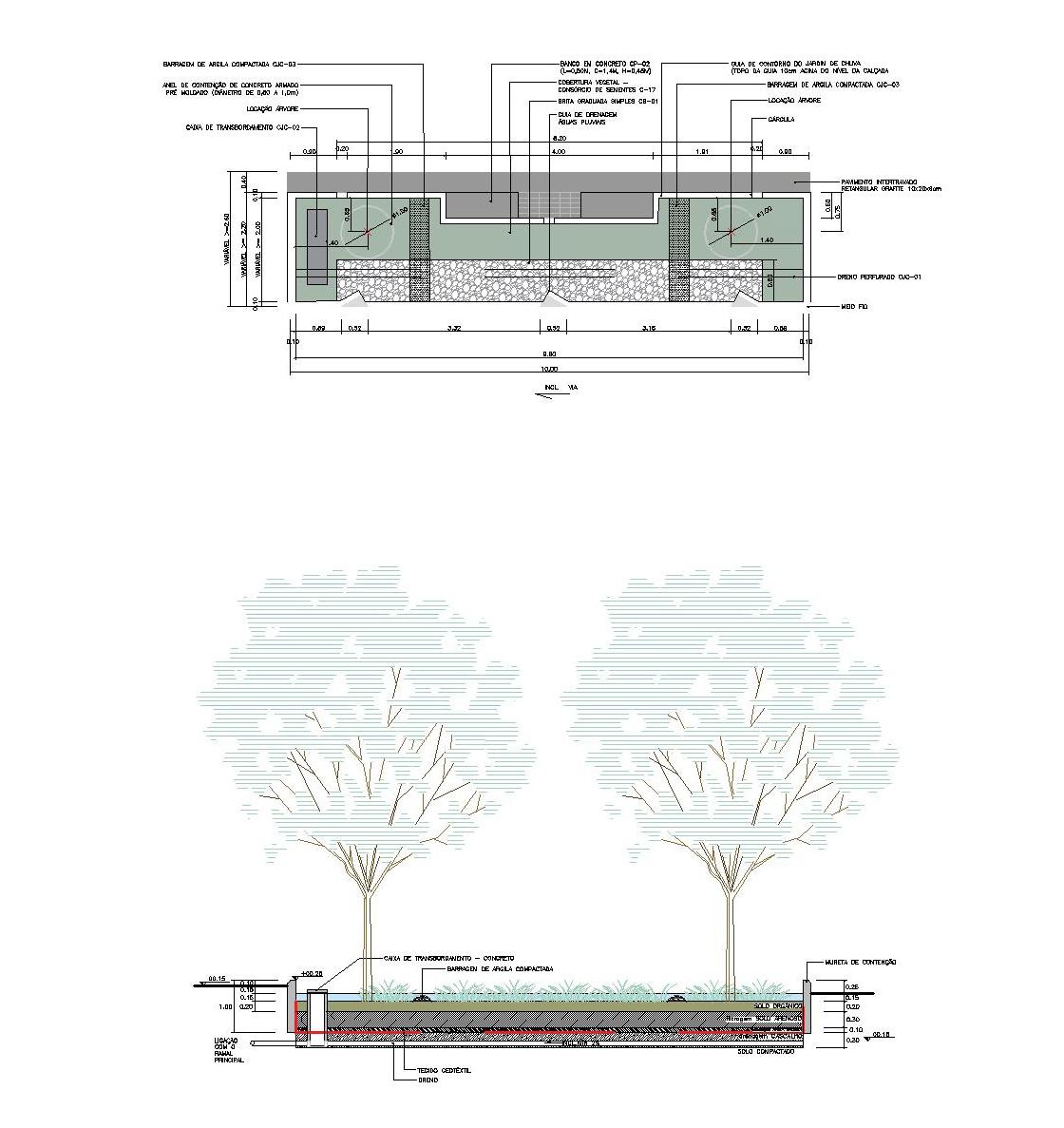 PLANTA | Jardim de chuva
PLANTA | Jardim de chuva
PLANTA | Jardim de chuva
LISTA DE PROJETOS
CYCLE INFRASTRUCTURE AND THE URBAN GROUND FLOOR
Synergy between high-capacity transport and active modes: implications on the urban ground floor
CYCLE PLAN STRATEGY: SÃO PAULO | Final Essay
CICLOMOBILIDADE | Jaçana - Tremembé
BRT CUIABÁ | 23 Sul
ESTUDO DE IMPLANTAÇÃO DE VLT | EGIS
SERPENTINA | The re-contact with nature
SPINE | Integrating housing in an industrial area
PARQUE DE VÁRZEA JD. HELENA | Recuperação da várzea do Tietê
PORTO FLUVIAL DE PASSAGEROS | Transição e transporte
ESTUDO DE IMPLANTAÇÃO DE VLT
Estudo de viabilidade de implantação de uma linha de Veículo Veve sobre Trilhos (VLT) na cidade de Maceió
Local: Maceió - Alagoas
Brasil Em colaboração com: Egis 2021
O trabalho focou no estudo de viabilidade da implantação de uma linha de VLT na cidade Maceió. A linha tem por objetivo ligar o centro à uma região majoritariamente residencial ao norte. A partir de uma proposta de traçado, estudou-se restrições e possibilidades físicas para a linha.
Como método de sistematização foram avaliados os pontos de maior interesse para desenvolvimento do estudo, como cruzamentos, vias
demasiadamente estreitas ou largas, raios de curvatura, dentre outros. Por variáveis físicas foram adotadas inclinação das vias, raio de curvatura do trem, restrições de leito viário e impactos no entorno. Por impactos sociais, levou-se em consideração possíveis consequências que a linha traria para os moradores ou proprietários ao longo desta.
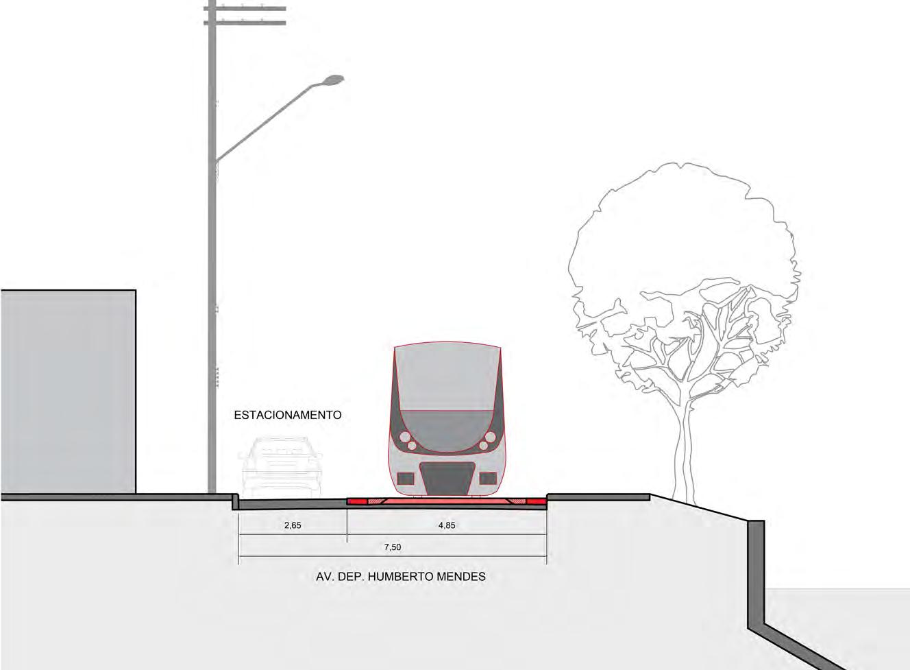
De acordo com o manual/norma/lei/diretriz O raio mínimo de curvatura para o trem do VLT é 100 metros. A inclinação máxima da via que o trem pode superar é 2%; e, para o modelo de trem proposto, a caixa mínima, levando em consideração o gabarito dinâmico, é 4,85 metros.
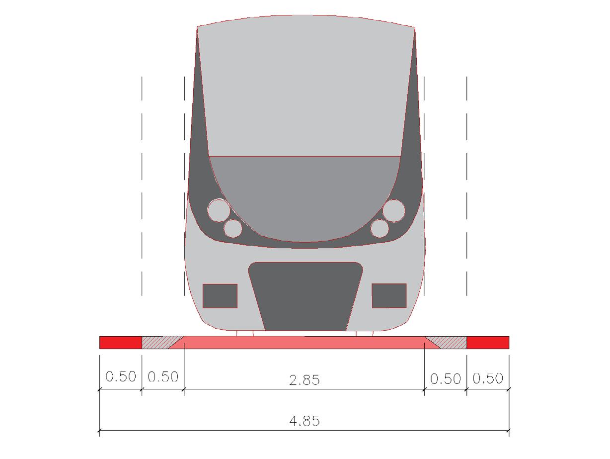
Largura total de implantação.
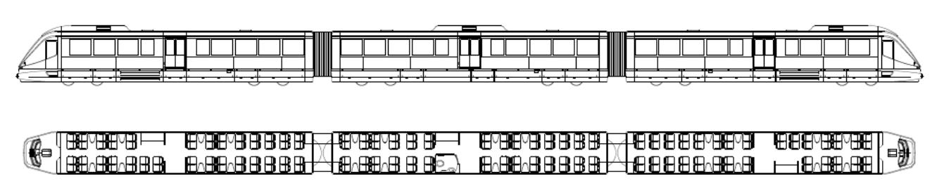
Para este estudo foi usado o trem Mobile 3R (3 carros) da empresa Bom Sinal, que atende à demanda requerida para a linha. A empresa já atua em Maceió, e forneceu trens para o sistema de VLT de Juazeiro, Fortaleza, Recife, dentre outras cidades brasileiras.
O trem possui largura aproximada de 2,85 metros e recomenda-se uma faixa livre de 1,00 metros para cada lado, garantindo o gabarito estático e de segurança em vias retas e curvas.
Características:
Velocidade máxima: 80 km/h
Freio de serviço 0,8 m/s
Raio mínimo da curva: 90m
MOBILE 3R, 164 a 488 passageiros, comprimento total de 57.350,00mm. Fonte: Bom Sinal.GABARITO ESTÁTICO GABARITO DINÂMICO GABARITO ESTÁTICO GABARITO DINÂMICO
No total foram feitos 19 estudos de situações, os quais 5 são apresentados aqui.
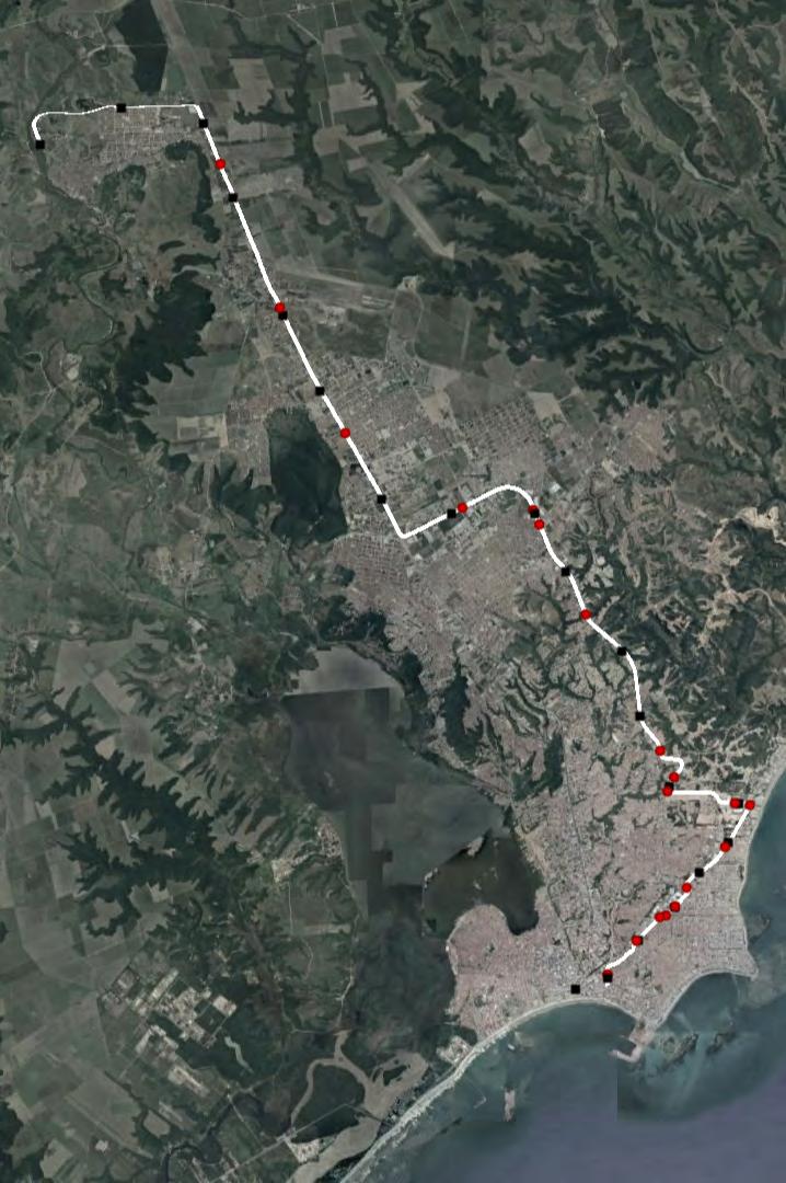
0
Estações propostas Pontos de estudo
2,5km Mapa: Google Earth 2023
1 2 3 45 6 7 8 9 10 11 12 13 14 15 16 17 18 19
IMPLANTAÇÃO | Proposta de trajeto com estações e locais de análise da situação urbana (enumerados).
ANÁLISE
Quadra de uso misto
Via de sentido único
Leito viário estreito
Proibição de estacionamento junto ao meio-fio
Limitação física do curso d’água já canalizado com pequena área permeável de contribuição de várzea
SITUAÇÃO 01 | Av. Cid Scala.
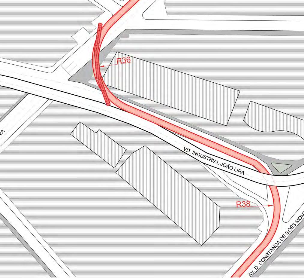
SITUAÇÃO 06 | Curva em S da Av. D. Contança de Goés Monteiro a sul e Av. Comendador Gustavo Paiva a norte. A esquerda curva permitida pelo desenho urbano existente, e a direita curva requerida pelo sistema de VLT.
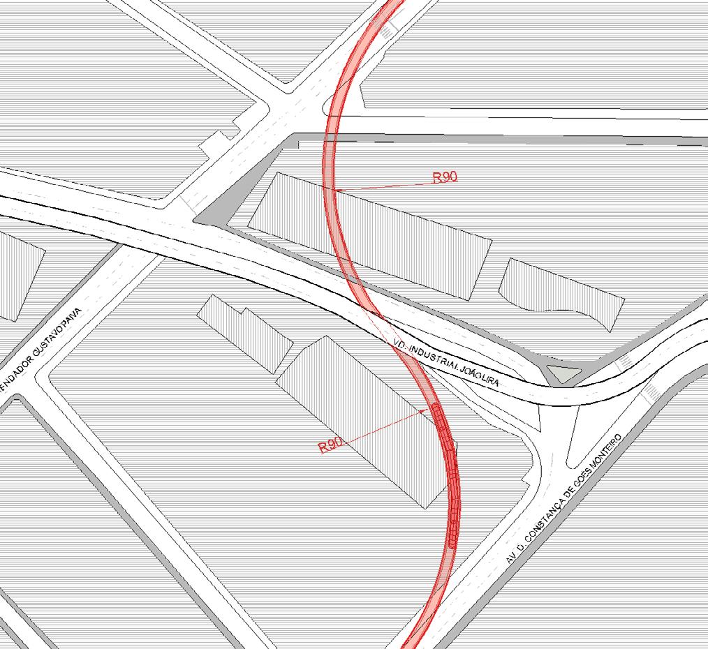
ANÁLISE
Urbanização consolidada nos lotes lindeiros à curva
Edifícios comerciais ao longo do trecho
Desenho viário não permite raio mínimo para curvas do trecho
Duas curvas consecutivas
APLICÁVEL
Curva em S com raio menor que 100 metros sob um viaduto
NECESSÁRIO
Curva em S com raio maior que 100 metros
Necessidade de desapropriação para raio de curvatura requerido
ANÁLISE
Vias existentes não permitem curva à esquerda com raio de 90 metros
Lote da esquina interna do desenho equivale a um Shopping Center. Entretanto a área requerida corresponde ao estacionamento do estabelecimento, o que sugere uma desapropriação sem grandes impactos
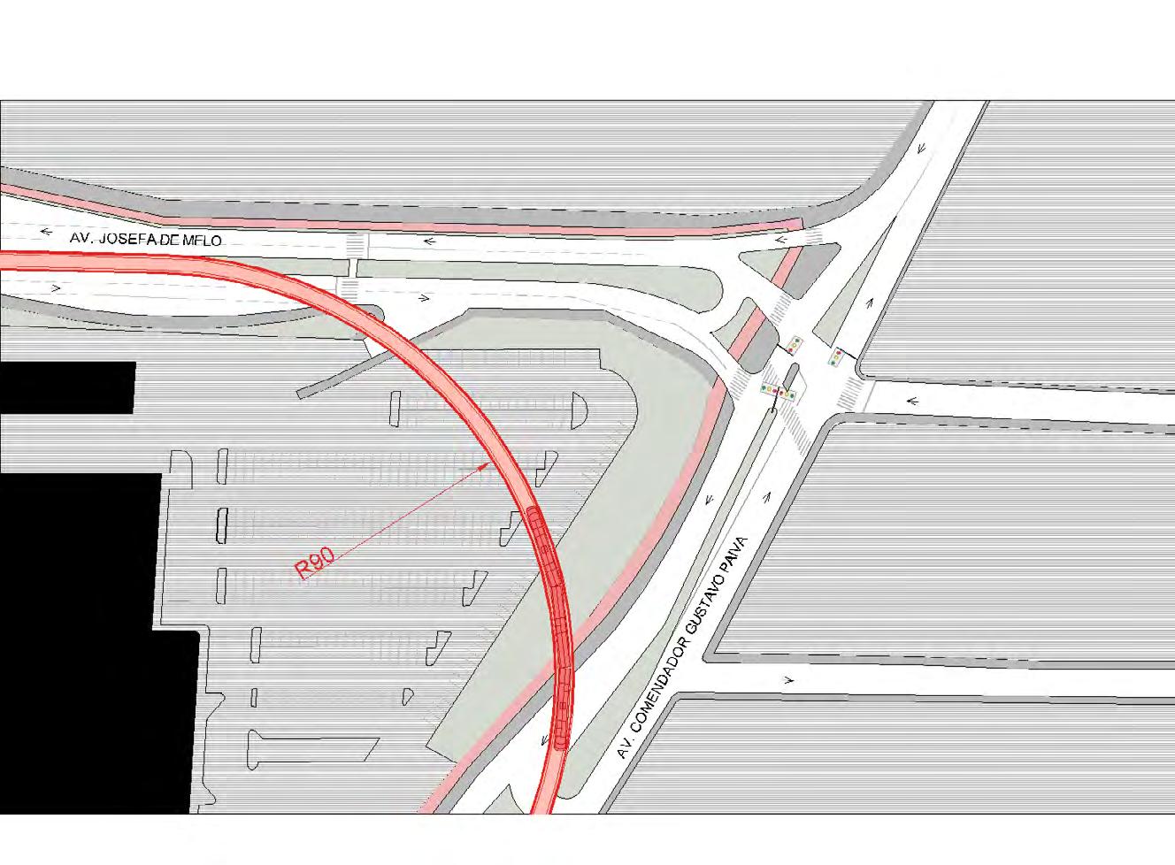
SITUAÇÃO 08 | Curva à esqueda.
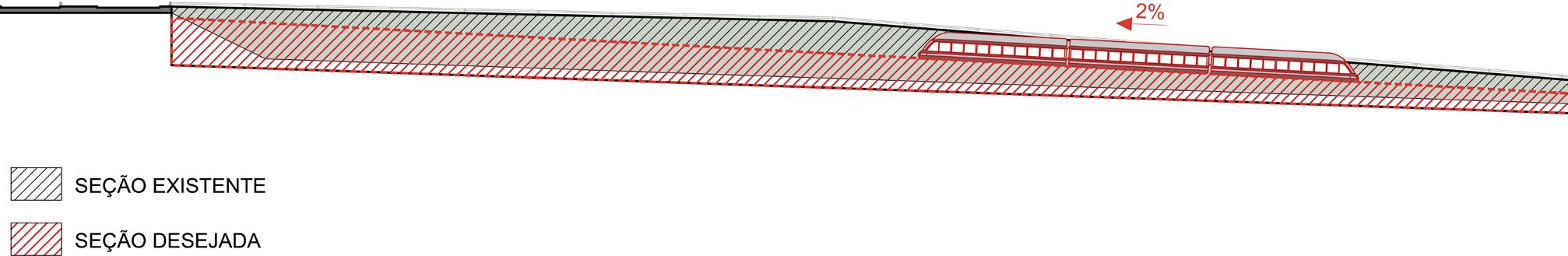
SITUAÇÃO 10 | Inclinação a ser superada pelo trem, da Av. Josefa de Melo em direção à Av. Juca Sampaio.
ANÁLISE
Inclinação para superar a elevação a partir da via existente é superior a inclinação máxima possível de 2%
para efetivação da rampa é necessário aumentar a distância percorrida, alongando a via
ANÁLISE
Av. Lourval Melo Mota caracteriza-se por ser uma avenida larga com 6 faixas de rolagem para veículos e um canteiro central de (neste trecho) 8 metros de largura
Implantação da linha de VLT no canteiro central não afeta o fluxo neste trecho, mas requer supressão de vegetação existente
É necessário estudar o carregamento desta avenida, pois uma vez sua generosa largura, há a possibilidade de manter as árvores existentes e implantar a linha de VLT sobre uma das faixas de rolagem
Como conclusão desse estudo de implantação avaliou-se que para implantação do VLT algumas mudanças urbanísticas deveriam ser feitas, incluindo desapropriação de áreas urbanizadas e grandes empreendimentos como torres comerciais. Além, algumas mudanças do fluxo viário e adequações se fazem necessárias, o que requer um estudo de ruas ao redor. Além, é possível dizer que o maior ponto de fragilidade do sistema está nas curvas requeridas, que necessitam raio mínimo de 90 metros.
Portanto, para esse percurso, este sistema de VLT não seria o tipo de transporte de maior benefício de implantação, levando em conta a demanda necessária para o trecho e as necessidades de implantação. Logo, recomenda-se para este percurso um sistema mais maleável e flexível às variáveis urbanas pré-existentes, como o BRT (Bus Rapid Transport), que garante a oferta desejada.
Apesar, frisa-se que o VLT é uma forma de transporte, que apesar do alto custo de implantação, traz enormes benefícios para o meio urbano, pois gera um menor impacto, tanto ambiental como na paisagem. Ainda, ele se enquadra no tipo de meio de transporte de sistema fechado, ou seja, sem interferência externa, por estar em uma via segregada, garantindo periodicidade e frequência, aumentando a confiabilidade dos usuários.
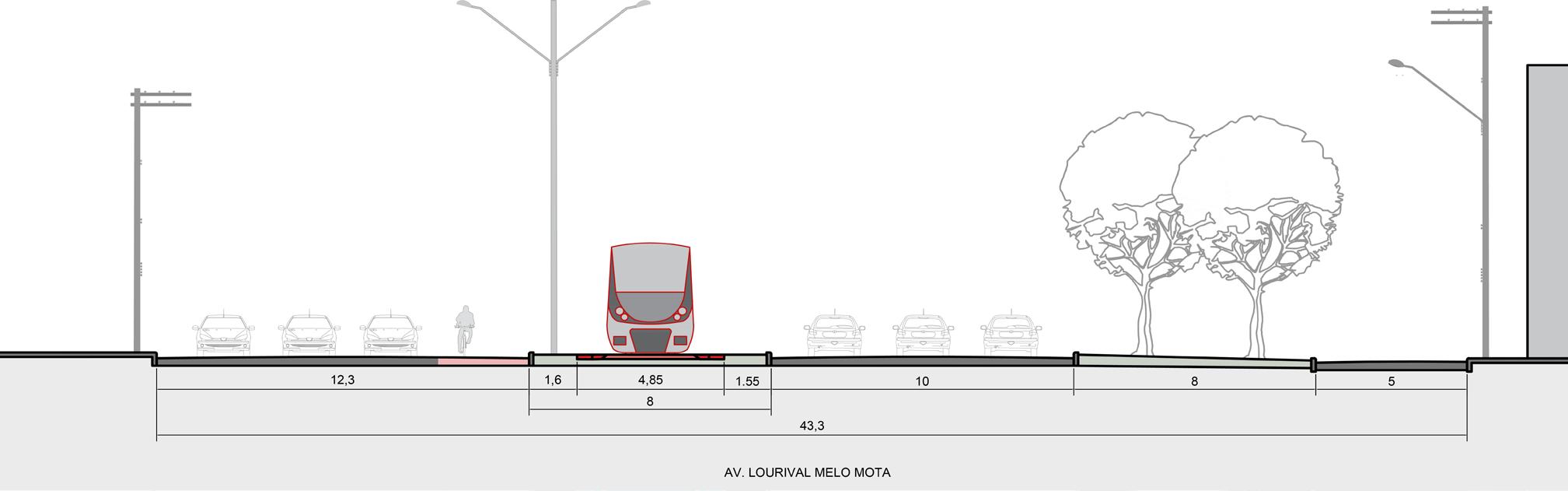
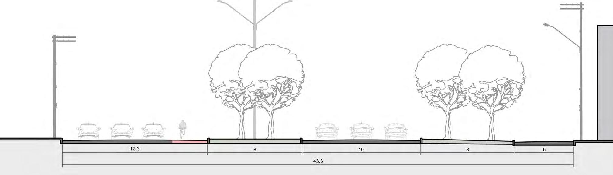 SITUAÇÃO 16 |
Av. Lourval Melo Mota, antes e depois da implantação da linha de VLT.
SITUAÇÃO 16 |
Av. Lourval Melo Mota, antes e depois da implantação da linha de VLT.
LISTA DE PROJETOS
CYCLE INFRASTRUCTURE AND THE URBAN GROUND FLOOR
Synergy between high-capacity transport and active modes: implications on the urban ground floor
CYCLE PLAN STRATEGY: SÃO PAULO | Final Essay
CICLOMOBILIDADE | Jaçana - Tremembé
BRT CUIABÁ | 23 Sul
ESTUDO DE IMPLANTAÇÃO DE VLT | EGIS
SERPENTINA | The re-contact with nature
SPINE | Integrating housing in an industrial area
PARQUE DE VÁRZEA JD. HELENA | Recuperação da várzea do Tietê
PORTO FLUVIAL DE PASSAGEROS | Transição e transporte
SERPENTINA
The re-contact with nature
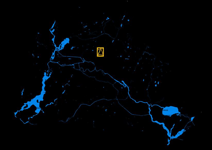
L ocal: Bandeira Bridge, São Paulo - SP Brazil
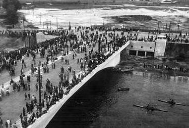
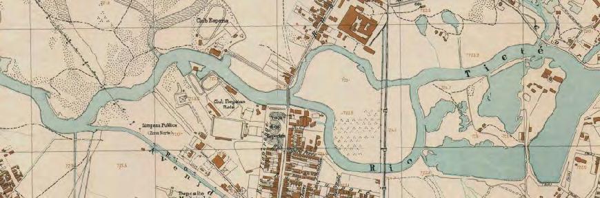
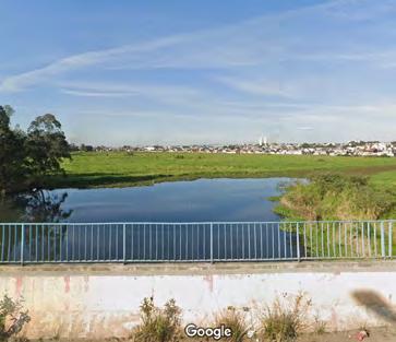
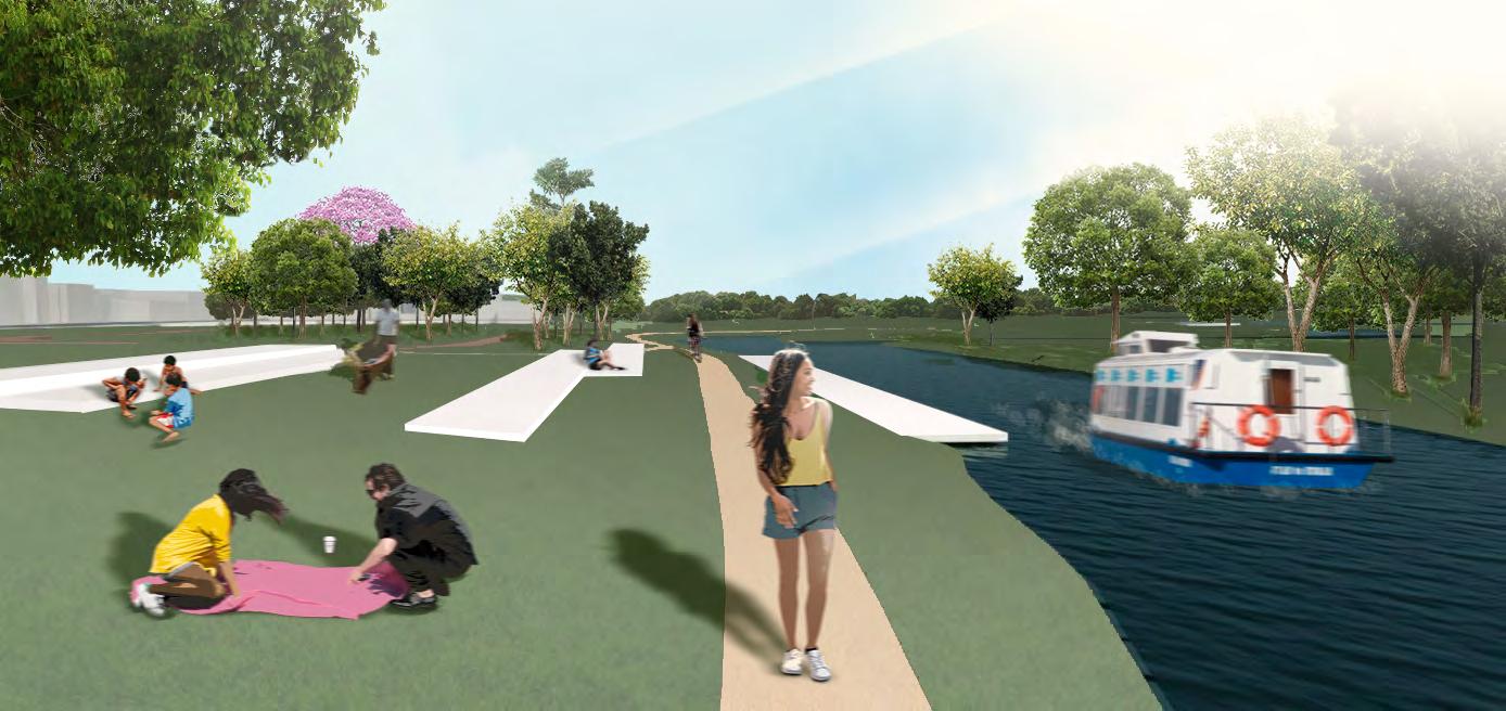
The project is based on Bandeira bridge, which crosses the most significant river in São Paulo, the Tietê. The river has considerable importance and permeates not only the city’s terrain but also its history and development.
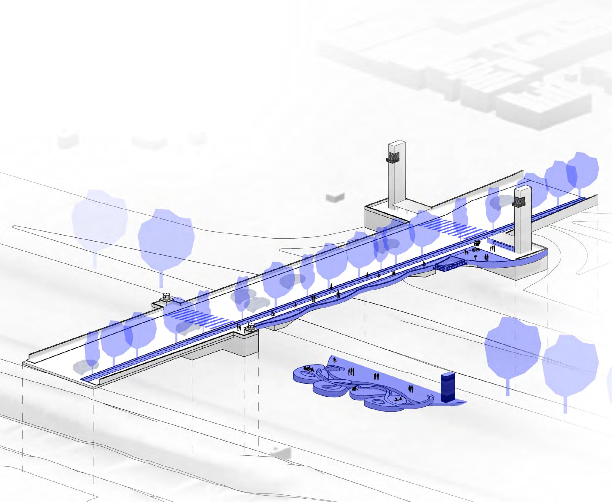
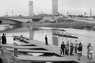
Serpentina is a project inspired by the nostalgic interaction between players of regattas and the waters of Tietê. This beloved sport stopped being practiced in 1972 as a consequence of water pollution, and since then the river has never recovered from the uncontrolled urbanization problems.
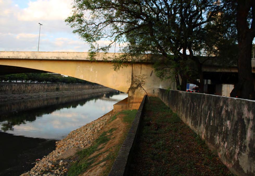
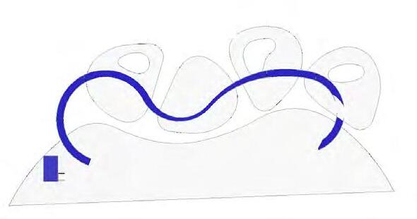
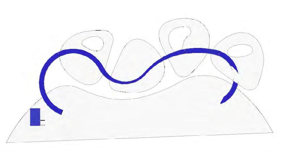
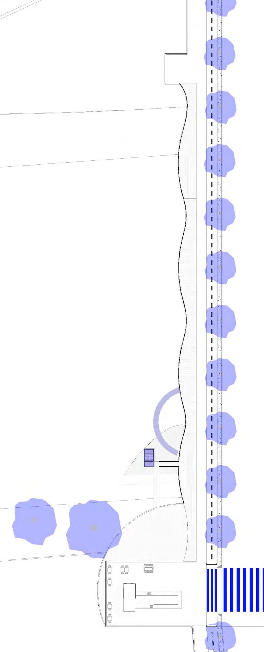
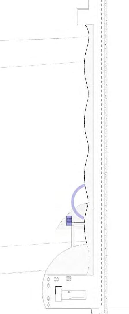
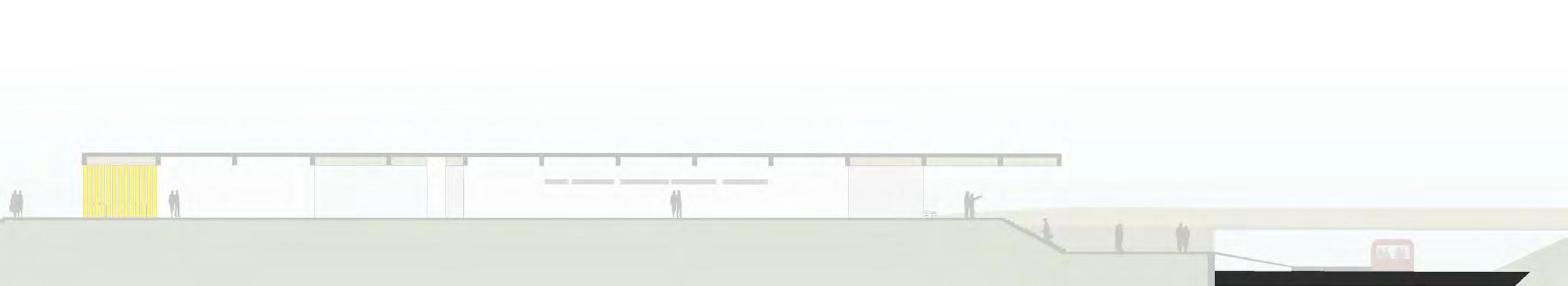
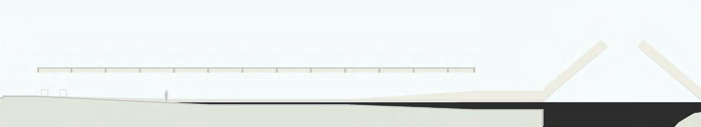
Therefore, the proposition consists of the effort to bring this contact back by the creation of 4 floating decks and a pier - contemplation deck, that provides close contact with the water, a vertical connection, a wooden walkway - boulevard, that brings some visual comfort, and a cafe by the bridge towers to encourage people’s permanence.
Lunawood Challenge re-imagine and redesign urban enviroments by using Lunawood Thermowood
Co-authorship: Barbara Sula and Veridiana Bengela Tersi 2021
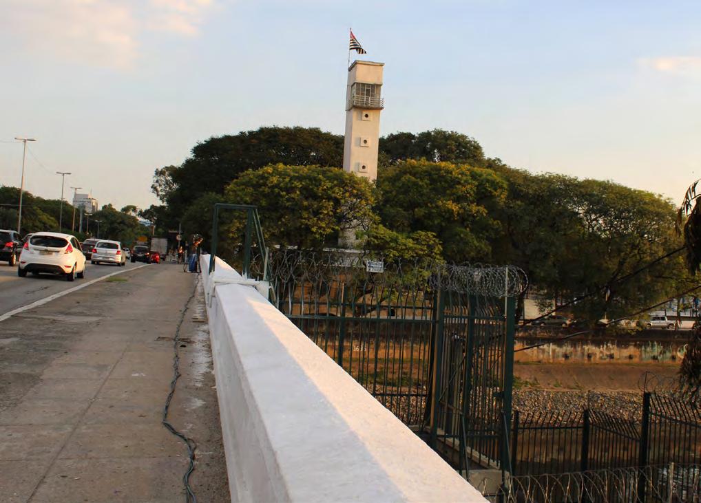
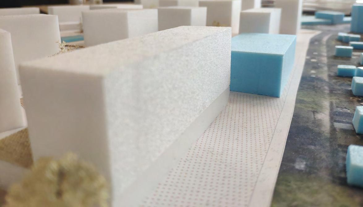
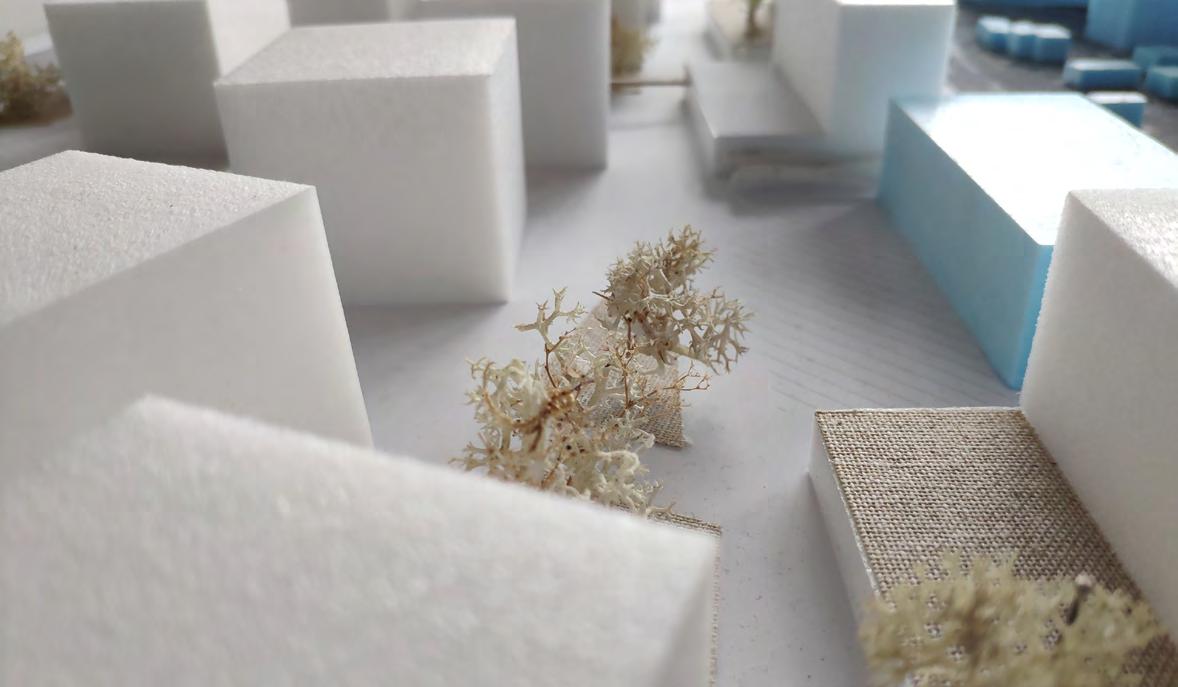
These towers were used as watch spots in competitions and today are completely abandoned. The project will bring back liveness and give proper use to the old installations. In this way, Serpentina aims to recover the attractiveness of this site by inviting citizens through the construction of a safe outdoor space and the use of natural wood. The curved forms and the feature that connects the different piers refer to the prior curves of the river, which were lost during the process of rectification and road construction. The project is experienced piece by piece as a serendipity of events led by the blue structure, and the stair. Moreover, serpentina is the name of a colorful rolled-paper toy that Brazilians play with in festivities. This feeling is what we hope to evoke with the project.
Serpentina | ExplosionHISTORICAL BACKGROUND
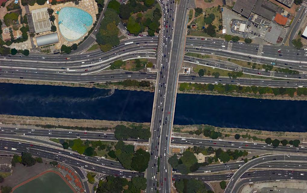
Actual situation
São Paulo - SP. Data: Geosampa
Location Plan, Bandeira Bridge, Tietê river. Data: Google satellite.
Bandeira Bridge
Regata competition, around 1940. Source: Palmeiras Football Club
Regata competition, around 1950. Source: Estado Agency.
Tietê River, 1930. Source: SARA Maps.
BANDEIRA BRIDGE
The forms proposed are inspired by the natural river bank design, typically formed on plan terrain and highly altered during the construction of the marginal roads.
Permanence uses Commerce
Transitions, passage
Floor Plan, Bridge level | Original scale 1:200
Floor Plan, River level | Original scale 1:200
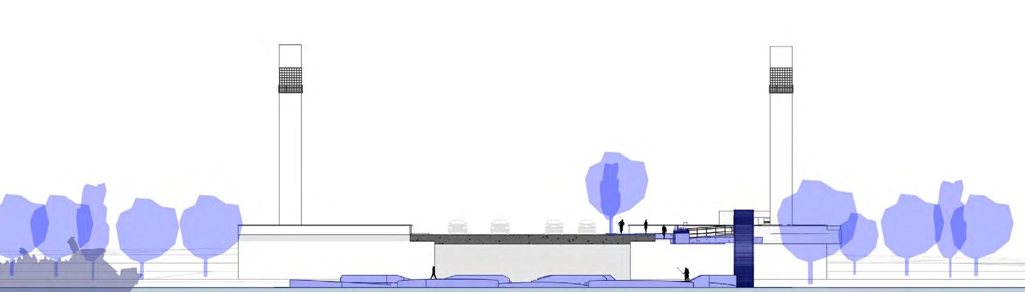
Cross section | Original scale 1:200
CAFE PATIO BRIDGE PLAZA FLOATING DECK FLOATING DECK FLOATING DECK FLOATING DECK STAIRCASE STAIRCASE BOULEVARD CONTEMPLATION DECK CONTEMPLATION DECK river level BOULEVARD bridge level
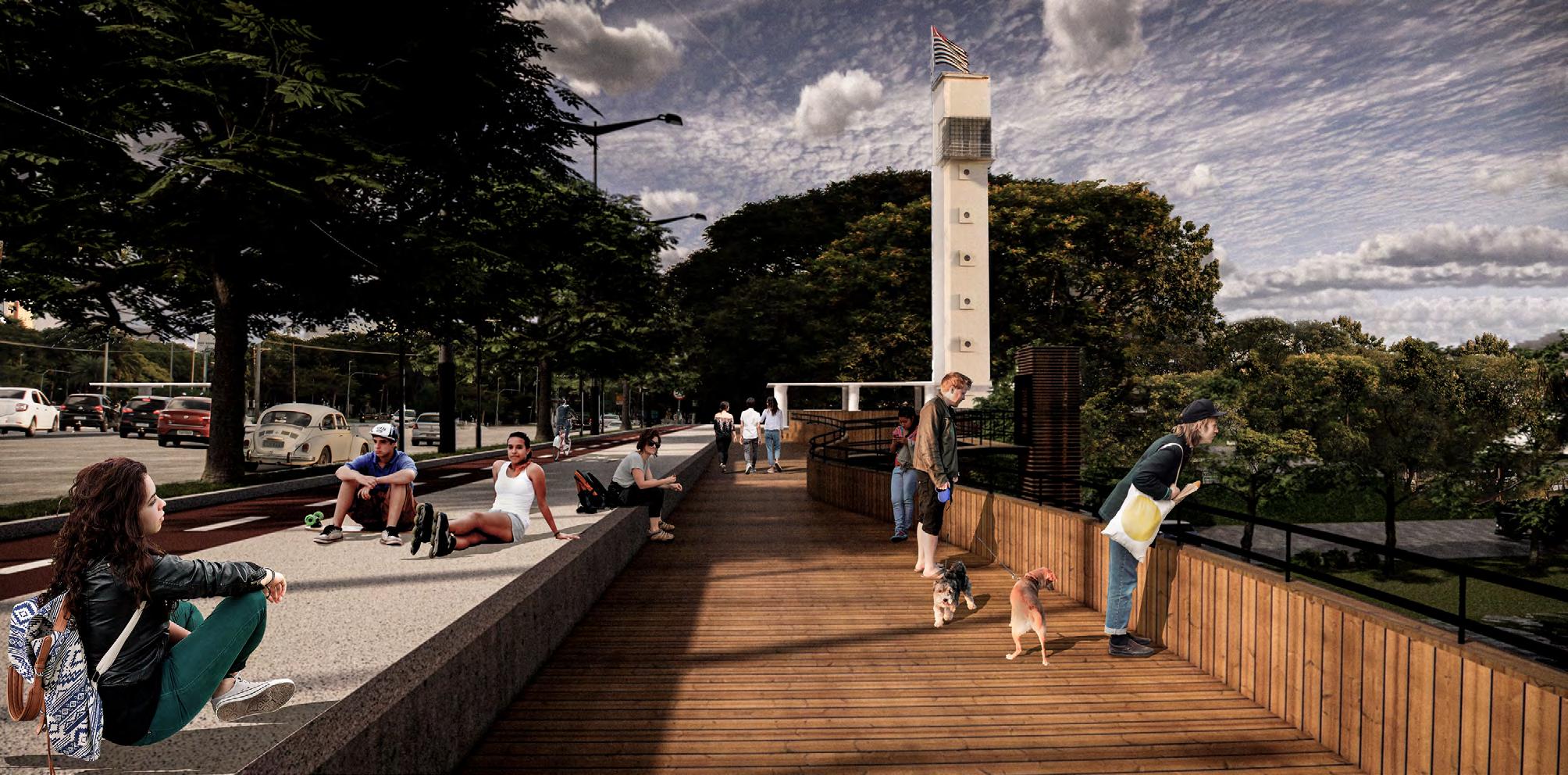
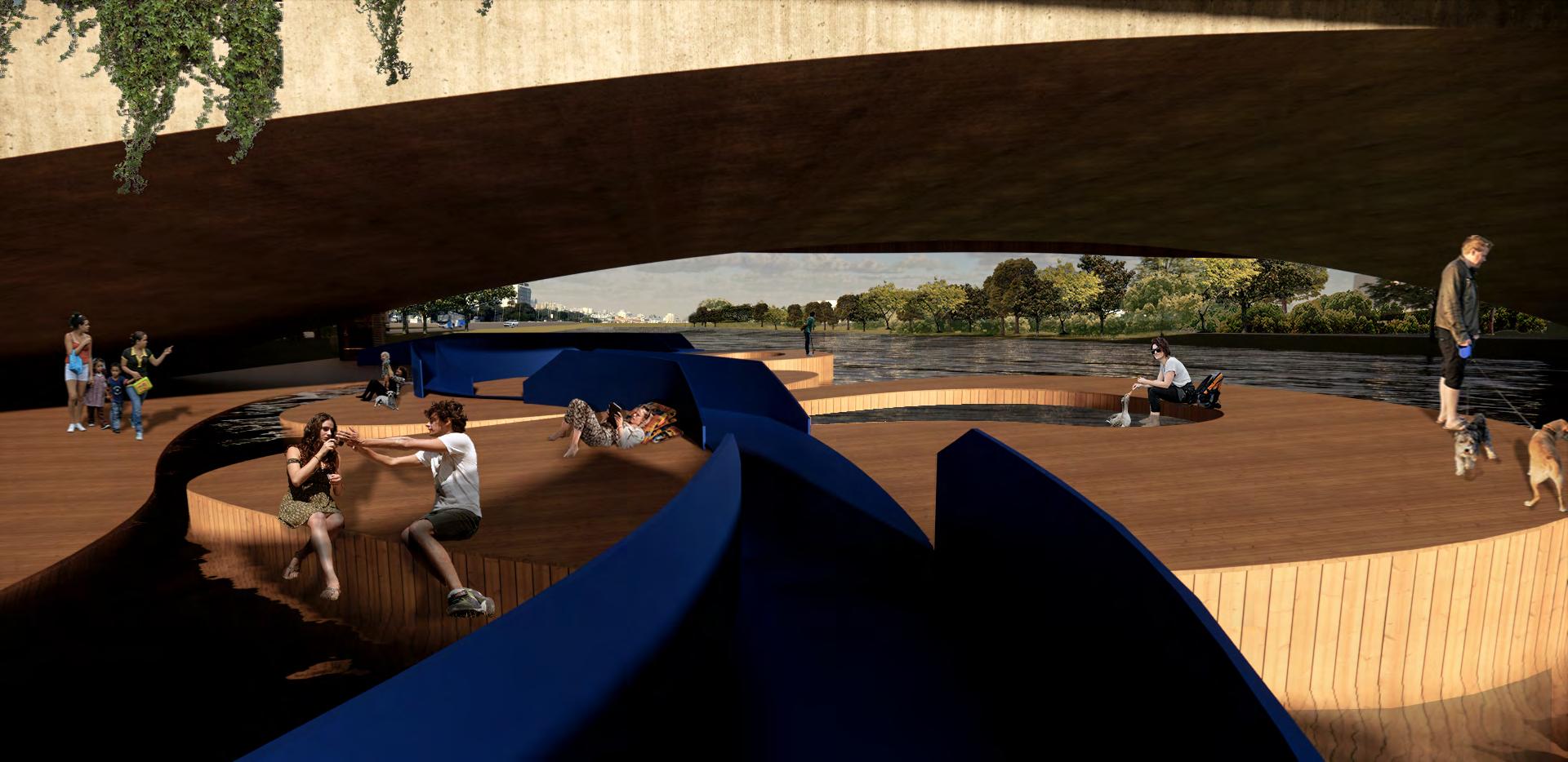
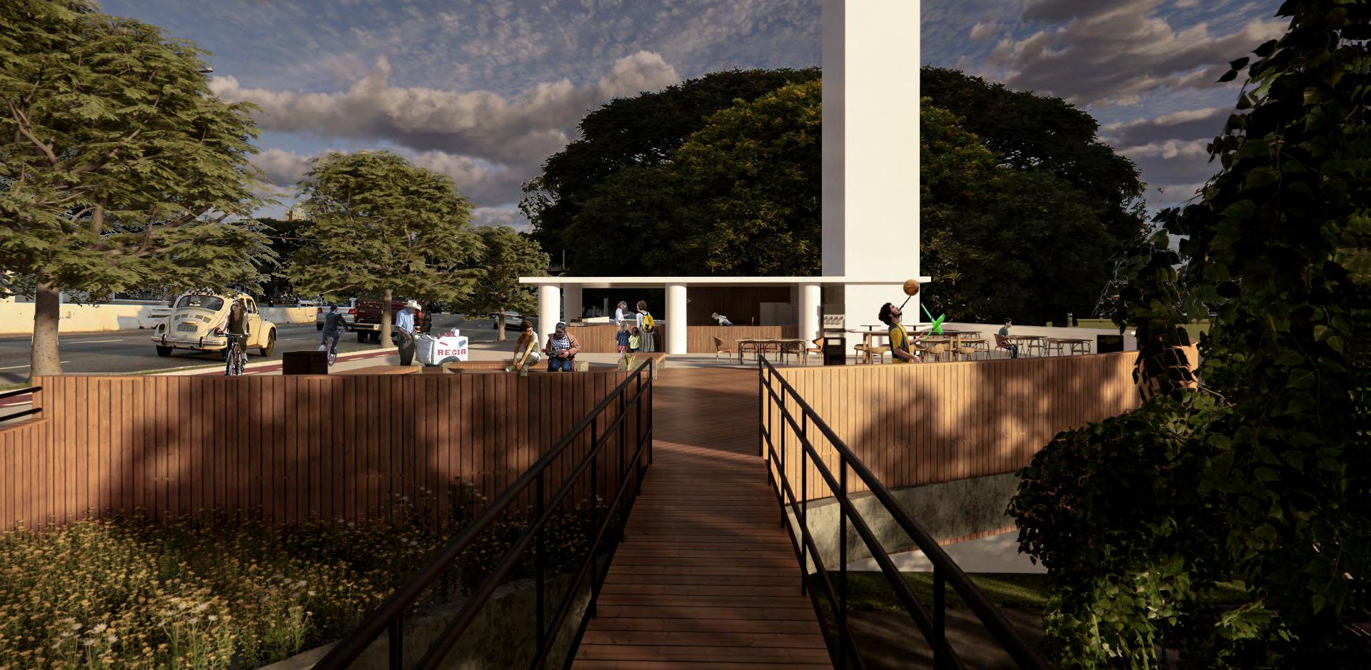 Bridge Boulevard
Floating decks
Bridge cafe
Bridge Boulevard
Floating decks
Bridge cafe
LISTA DE PROJETOS
CYCLE INFRASTRUCTURE AND THE URBAN GROUND FLOOR
Synergy between high-capacity transport and active modes: implications on the urban ground floor
CYCLE PLAN STRATEGY: SÃO PAULO | Final Essay
CICLOMOBILIDADE | Jaçana - Tremembé
BRT CUIABÁ | 23 Sul
ESTUDO DE IMPLANTAÇÃO DE VLT | EGIS
SERPENTINA | The re-contact with nature
SPINE | Integrating housing in an industrial area
PARQUE DE VÁRZEA JD. HELENA | Recuperação da várzea do Tietê
PORTO FLUVIAL DE PASSAGEROS | Transição e transporte
SPINE INTEGRATING HOUSING IN AN INDUSTRIAL AREA
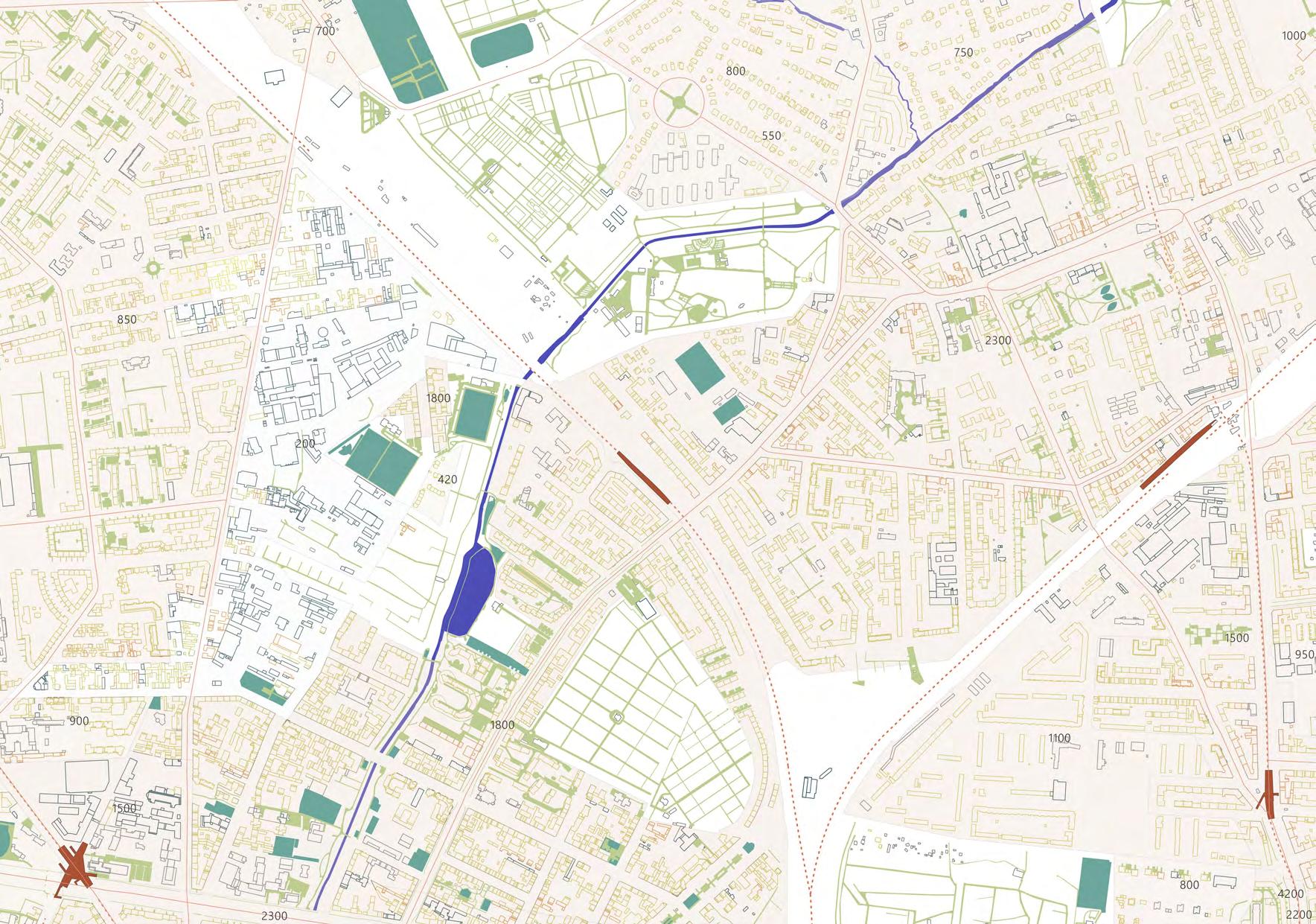
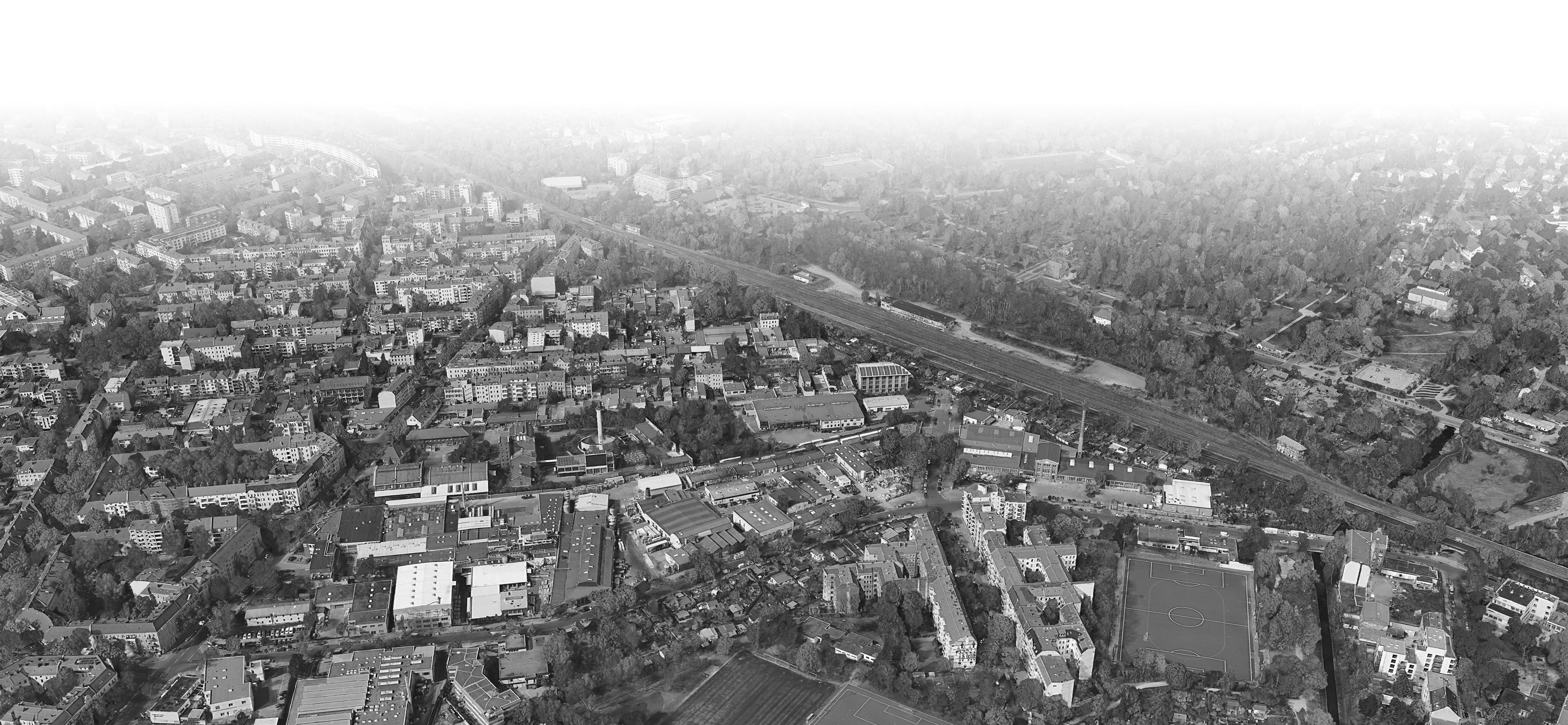
A sudden change in major urban circumstances usually entails a change in urban structure of the immediate surrounding as well. The chosen industrial area, in the north and intersection of Gesundbrunnen and Reinickendorf Districts, will be effected by such a change. The planes’ air-route of the nearby airport ‘Berlin Tegel’ is jsut above the area. Once the airport closes in 2020 though, a rapid improvement in local noise pollution will take place. This will make the area more attractive for future housing projects. Therefore a change of the local real estate valuation can be expected. Meanwhile, with the anticipated shut
down of Tegel airport, the surrounding real estate is being afflicted by financial speculation. Countless small industrial units have been sold, torn down and re-erected as uniform residential projects. This procedure is particularly bad for many production sites inside the chosen project area. The dynamics of the property market and its rising market pressure will eventually force all the production out of the inner city into the periphery. In order to avoid unwelcome changes in urban diversity, the chosen area has to be rethought, before the rising market pressure uncontrollably interferes.
Orientadored by: Germain Chan, Ali Saad Urban Systems
TUBERLIN - URBAN DESIGN 2019/20
Local: Gesundbrunnen and Reinickendorf Berlin, Germany
 Barbara Sula Braga
Ana Elisa Vargas Lópes
Fabian Prissok Pia Drewes
Barbara Sula Braga
Ana Elisa Vargas Lópes
Fabian Prissok Pia Drewes
low market segment: 6,39 euros/m²/month (Bez. 7 eu) high market segmentt:

H P S
Synthetic Map | 1 : 20.000
Location Plan | 1: 20.000
Source: FisBroker housing mix use industry and commerce 100
sport facitily green river and body of water land
bus line train line station
5000 euros/m²
price
351
Currently, there are around 351 rent offers, that correspond to 6% of the district
The price average for renting/ m² is approx. €10,41 (all segments) in the site of study, for the district is approx. €12,5
The avarage age for the district of Gesundbrunnen is 38,9 years
Historical Change | Gesundbrunnen
1860
13,6% < 15 years
9,4% 15 to under 25
31,5% 25 to under 45
26,4% 45 to under 65
19,1% 65 and more

6KM
The area is 6Km far from downtown and has good public transportation offer source:Senatsverwaltung für Stadtentwicklung und Wohnen Montoring Soziale Stadtentwicklung 2017
1930
Industry shrinkage Industry in the outskirts of the city
Industrial Revolution - High level of industrialisation
Gradual expansion
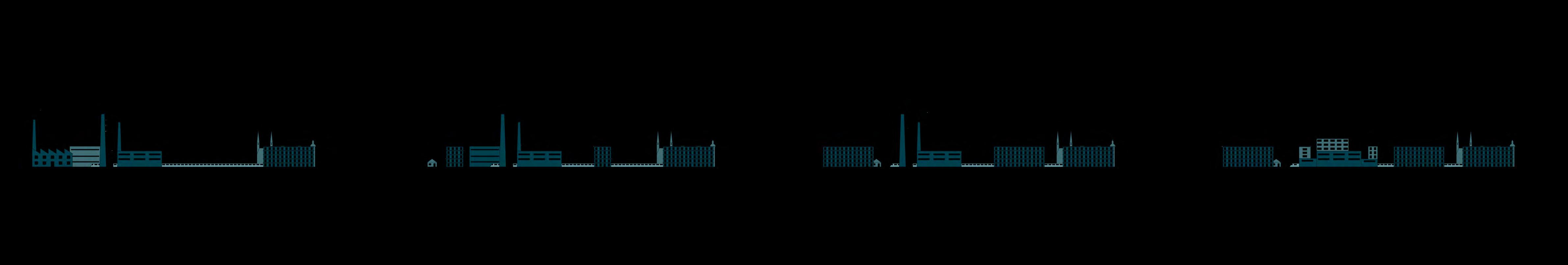
Post-War I recession - Treaty of Versailles - Golden Twenties - Depression of 1929 Big impact in Germany’s economy
2035
Expansion and horizontal densification Tension Tension

Post World War II - Marshall Plan - Berlin Wall - City Border - Spatial Conflicts

Vertical densification
Industry transformation (Industry 4.0) and Berlin Strategy Plan to 2035 Productive, efficient and health city - coexistence of production and housing

Analysis | Existing Area
38,8% of the residents are not from Germany
Phase 0


Existing area Spine as an integration tool
Phase l Carshops + free spot 1 yr. plan
Phase ll Smaller companies 10 yr. plan
Phase lll Big companies + expanding bridge 20 yr. plan
building for medium industry, located next to the street ground floor manufacturing/light
STRATEGY UNITS WEEK WORKING DAY NIGHTENTERTAINMENT R E S I D ENTS MOC M E R C E OFFICE NOITCUDORP LOGISTIC PUBLICLIFEINDUSTRIAL ACT I V I T Y Weekdays Weekends Cultural Building Spine Building Logistical Building Square Building Industrial Hub Communal Center ⇡ ◉ flex ble use square cu ura bu ld ng ✚ housing ndus r a hub ogist c bu d ng ✚ culture ⦿ ogistics he ght ☄ noise buffer ⇡ ◉ flex b e use square cu tura bu d ng ✚ housing ndustr a hub og st c bu d ng ✚ culture ⦿ log stics height ☄ noise buffer ⇡ ◉ flex ble use square cu ura bu d ng ✚ housing ndust a hub og st c bu d ng ✚ culture ⦿ ogist cs he ght ☄ noise buffer ⇣ ✚ housing exible use quare communal center ✚ housing sp ne bu ld ng square bu ld ng culture logistics ⦿ height ⇣ ✚ housing ◉ flexible use square communa center cu tura bui ding ng spine bui ding squ ✚ culture logistics logistics ⦿ height buffer ✚ housing ✚ housing spine bui ding square bui ding logistics ⦿ t tower for new kind of industry | offices and little storages
kitchen, kids area
semi-public uses (laundry, communal
existing
public activity industrial activity offices commercial/ public use others cultural housing medium industry light industry industry 4 0 commercial/ public use others cultural housing medium industry light industry industry 4 0
industry upper levels housing
building, cultural function ground floor manufacturing/light industry first floor commercial use
URBAN INDUSTRY
Types of Industry | Berlin
BALANCE OF USE
GFZ 0,4
Grundfläschezahl GRZ 0,7
Geschossflächenzahl GFZ 1,3
Grundfläschezahl GRZ 0,38
NEW PARAMETERS Urban Design
Urban Tools
In order to realize the project a certain set of urban development tool is used. In order keep production in the district, the area should be classified as urban area (‘Urbanes Gebiet’). To ensure a healthy mix of functions even more, certain conservation aims can additionally be specified inside the area. Old and protection worthy building substance should become sited, so they are freed of the marked pressure and can be developed into publicly used cultural centers.
The overall development of the project will happen in phases. At first small sized industry will indulge to the rising market pressure, because their least efficient land use and the low capital generation. Once their land is for sale, the city of Berlin is required to buy it first hand or to set directions for its buyers. Once sold, the area can be reconstructed accordingly to the project’s balance of uses. Little by little bigger industry units will also indulge to the market pressure, so that eventually the hole block can be redesigned. This way a metropolitan density will be brought to the district, while still maintaining the urban diversity.
The urban design main feature is the ‘Spine’. This large pedestrian bridge runs through the whole project area. It makes the urban block, more porous throughout all phases of the project, by opening up an additional level, bridging barriers and connecting buildings. This new porosity initiates the transformation of the hermetic industrial area.
From the Spine the project features different buildings’ types. On the perimeter of the block, slab buildings have medium industry on the bottom, communal and commercial use in the midsection, as buffers, and housing in the upper part. The inside of the block is defined by point buildings, there the ground floor houses light industry, commerce in the midsection and housing on top. Communal buildings mark the neighbourhoods centers and a larger tower marks the principal corner with a building housing technological uses and the industry 4.0. Between the slab buildings and the point buildings we have shared spaces, where the use is mainly defined by Industry during working hours and by the residents or visitors during the evenings or weekends. The elaborate layering and placement of the different functions transforms the industrial block into a urban project contributing to the diversity of an ideal inner city.
previous
Geschossflächenzahl
now
p b h hous ng med um ndus ry gh ndus y d t y 4 0
locations in compact city isolate/island locations growth of important locations new important locations special location floor space index site coverage index growth of important locations with special developing quality commercial/ public use others cultural use housing
GEWACHSENE GROSSSTANDORTE GEWACHSENE GROSSSTANDORTE MIT BESONDERER ERSCHLIESSUNGSQUALITÄT NEUE GROSSSTANDORTE SONDERSTANDORT STANDORTE IN KOMPAKTER STADT 851 2.158 686 402 210 0 10 20 30 40 50 60 70 80 90 100 147 INSELSTANDORTE commercial/ public use others cultural housing medium industry light industry industry 4 0 commercial/ public use others cultural housing medium industry light industry industry 4 0 commercial/ public use others cultural housing medium industry light industry industry 4 0 commercial/ public use others cultural housing medium industry light industry industry 4 0 commercial/ public use others cultural housing medium industry light industry industry 4 0 commercial/ public use others cultural housing medium industry light industry industry 4 0 commercial/ public use others cultural housing medium industry light industry industry 4 0
(Baasner Stadtplaner GmbH auf der Basis einer Sonderauswertung des Gutachtenausschusses Berlin 2010)
medium industry light industry industry 4.0 offices
Site Plan | 1: 2.000 Section AA | 1: 2.000 Section BB | 1: 2.000 og st c pocke A B green center FLEXIBLESQUARE(weeklymarkets) main entrance playground main entrance cultural center way up to spine ramp elevator Vl l l Vl Vl lll Vl Vl Vl Vl Vll Vll l l l Vll Vll lll V V Vlll Vl Vl l l l l l l l lll ll l ll lll ll l ll lll l l l l l l l l l V V V V V ENTRANCE SQUARE SHARED ACTIVITY SPACE temporary park ng exhibition furniture sale + exhibition carpenter ateliers SHARED ACTIVITY SPACE neighbourhood garden stude gard retirement home garden printing company p nt shop bar+tasting brewery residential garden urban gardening urban gardening childcare s garden glass workshop fitness center outdoor area urbanplayground makerspace bike repair locksmith marketgarden green house t re outside sto age boulecourts FLEXIBLE SQUARE (f ew markets public acti ities) temporary park ng hostel outdoors l e ect ic an Vl gardening shop pottery way up to spine screen print workshop tailoring instrument maker shoe maker wood workshop electrician textile production toys workshop e ectronic hop sto k sale stocksale stone carver stock sale main entrance Vl X INDUSTRIAL HUB communal center LUNCH COURT ALLOTMENTS CSPORTS OURTS main entrance "monopol PUBLIC SPACE cultural area COMMUNAL CENTER book shop records ca é restaurant co working café cinema bio market cooking studio +|- 0 00 + 500 + 5 00
mainentrance main entrance wayup to spine ramp elevator l Vlll Vlll Vlll Vll l tempo ary parking Y nts house en public park public park bakery textile ecycling bakery shop outs de stor ge skateboardproduction upholsterers workshop stocksale 3D printer production toy production
KIDSFARM PINKEPANKE
seminar space photo shop A B
SBAHNLINE PANKE
Explosion | Building types
heights public axis rooftop activities logistic pockets green spaces activity squares og st c pockets shared/flexible space coexistance rooftop act vities green spaces shared/flex b e space coex stance rooftop activ ties tensity of use centra publ c axis he ghts green spaces shared/flex ble space coexistance rooftop activ t es centra pub ic axis he ghts green spaces shared/flexible space coex stance rooftop act vities central pub ic ax s heights communal center childcare logistic pocket electrician 13,5 m 18 5 m 5 0 mSection | 1: 500
Explosion | Building types
intensity of use entrances green spaces shared space green spaces act v ty squares logistic pockets shared/flex b e space coex stance ooftop activ t es green spaces act vity shared/flexib e space coex stance rooftop activ ties central publ c axis he ghts green spaces activ ty squares ogist c pockets shared/flex ble space coexistance GS rooftop act vities intens ty of use central publ c ax s heights cookery studio food production logistic pocket logistic pocket shared space 3D printer production offices 27,5 m 24,5 m 5,0 m 5,0 mSection | 1: 500
makerspace c green house pottery furniture sale + exhibition ENTRANCE
temporary parking food store food production storage 3d printer laser studio e-car station industrial hub underground bike garage info point + administration - 4,00 +|- 0,00 +|- 0,00 +|- 0,00 +|- 0,00 +|- 0,00 residant entrance storage + delivery 1st floor stock sale storage store workshop lobby cafeteria store storage production +|- 0,00 office residant entrance
context 1:500 or 1:1000 Ground Floor Plan | 1: 500 main entrance
SQUARE
C3.1. Ground floor plan incl. urban
ramp elevator ENTRANCE
temporary parking urban gardening urban gardening textile production l l industrial hub cultural area book shop +|- 0,00 + 5,00 residant entrance + 5,00 + 5,00 + 5,00 + 5,00 + 5,00 office entrance + 5,00 re e +|- 0 00 a 2 room app bstudent app d 3 room app cstudio app a c d First Floor Plan | 1: 500
SQUARE
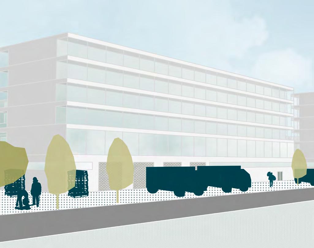

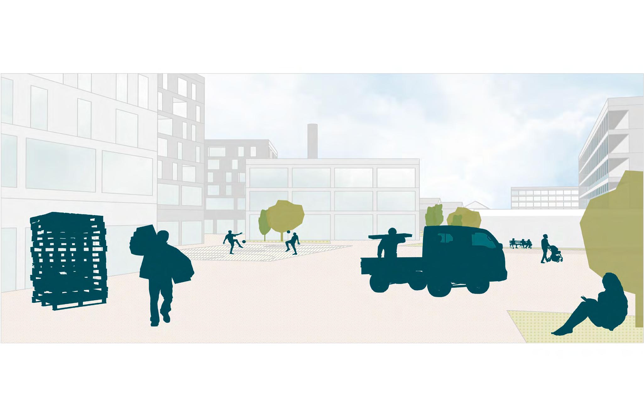
Project Situations
Logistic Pocket
Shared Space | Communal Building | Sport Court
Spine Entrance | Under Spine Situation, Logistic Robot
Spine Occupation
Shared Space | Cultural Building
Heritage Protected Area | leisure
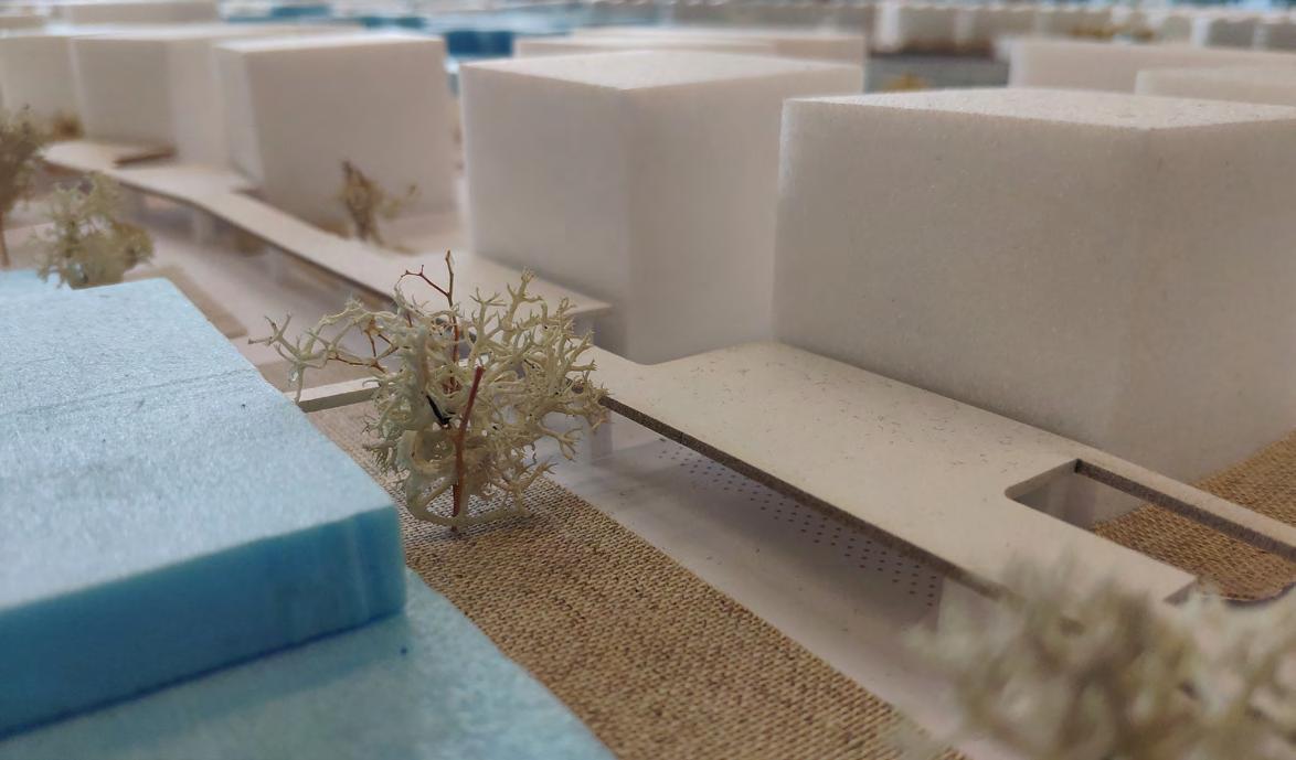
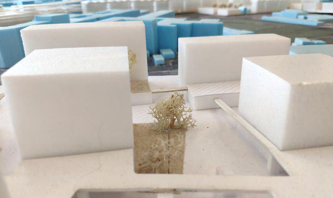
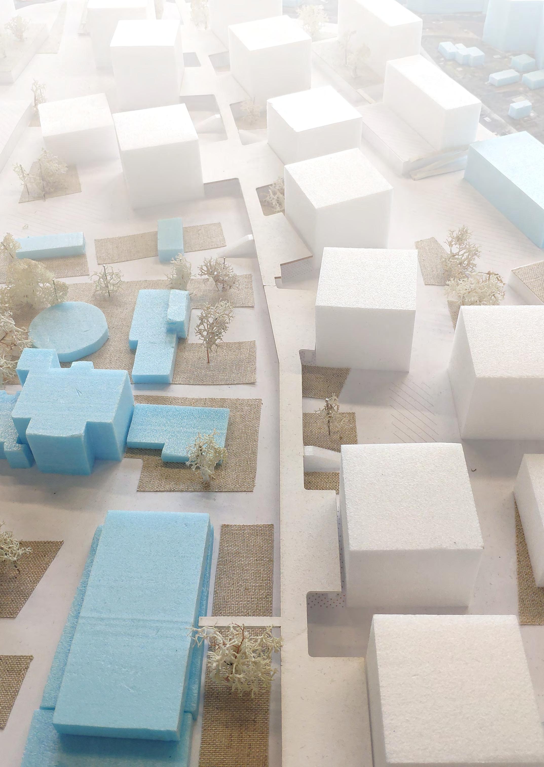
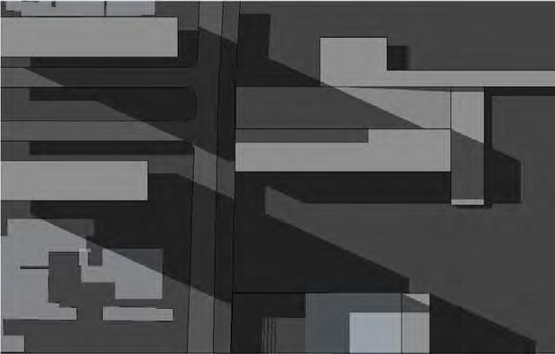
 Model Pictures
Shared Space
Spine
Shared Space
Logistic Pockets
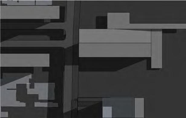
Model Pictures
Shared Space
Spine
Shared Space
Logistic Pockets
LISTA DE PROJETOS
CYCLE INFRASTRUCTURE AND THE URBAN GROUND FLOOR
Synergy between high-capacity transport and active modes: implications on the urban ground floor
CYCLE PLAN STRATEGY: SÃO PAULO | Final Essay
CICLOMOBILIDADE | Jaçana - Tremembé
BRT CUIABÁ | 23 Sul
ESTUDO DE IMPLANTAÇÃO DE VLT | EGIS
SERPENTINA | The re-contact with nature
SPINE | Integrating housing in an industrial area
PARQUE DE VÁRZEA JD. HELENA | Recuperação da várzea do Tietê
PORTO FLUVIAL DE PASSAGEROS | Transição e transporte
PARQUE DE VÁRZEA JARDIM HELENA
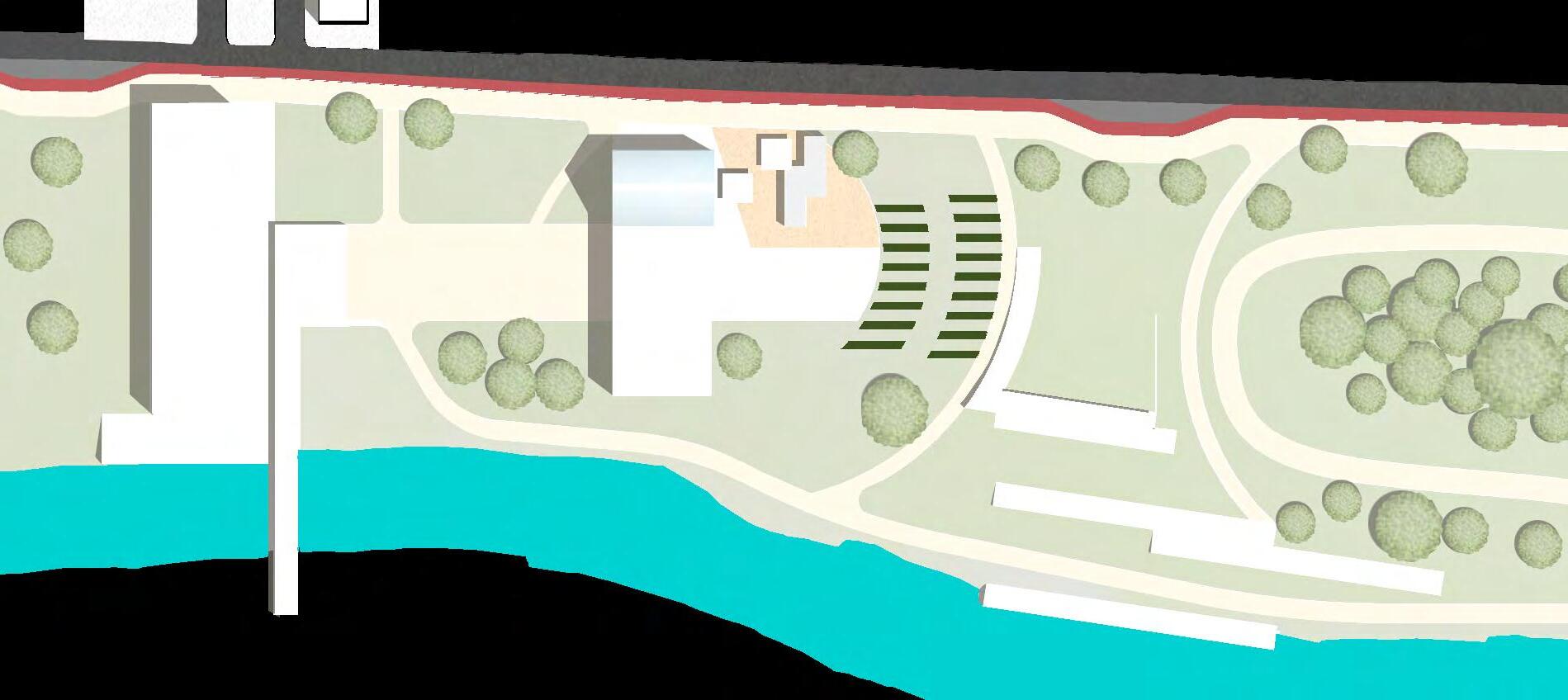
O Projeto Parque de Várzea Jardim Helena tem como base as propostas do Parque Várzeas do Tietê (PVT), do DAEE - Departamento de Águas e Energia Elétrico e Estado de São Paulo. Visando a importância da contenção das enchentes nas áreas urbanas próximas ao rio, assim como a manutenção da várzea e da vida natural, busca-se a preservação das águas, recurso finito e fundamental à vida. Ademais, pretende-se potencializar ao máximo o convívio da comunidade com a natureza através da educação ambiental, prática de hortas urbanas, esporte e lazer.
2020
Local: Jardim Helena e Itaim Paulista São Paulo - SP, Brasil
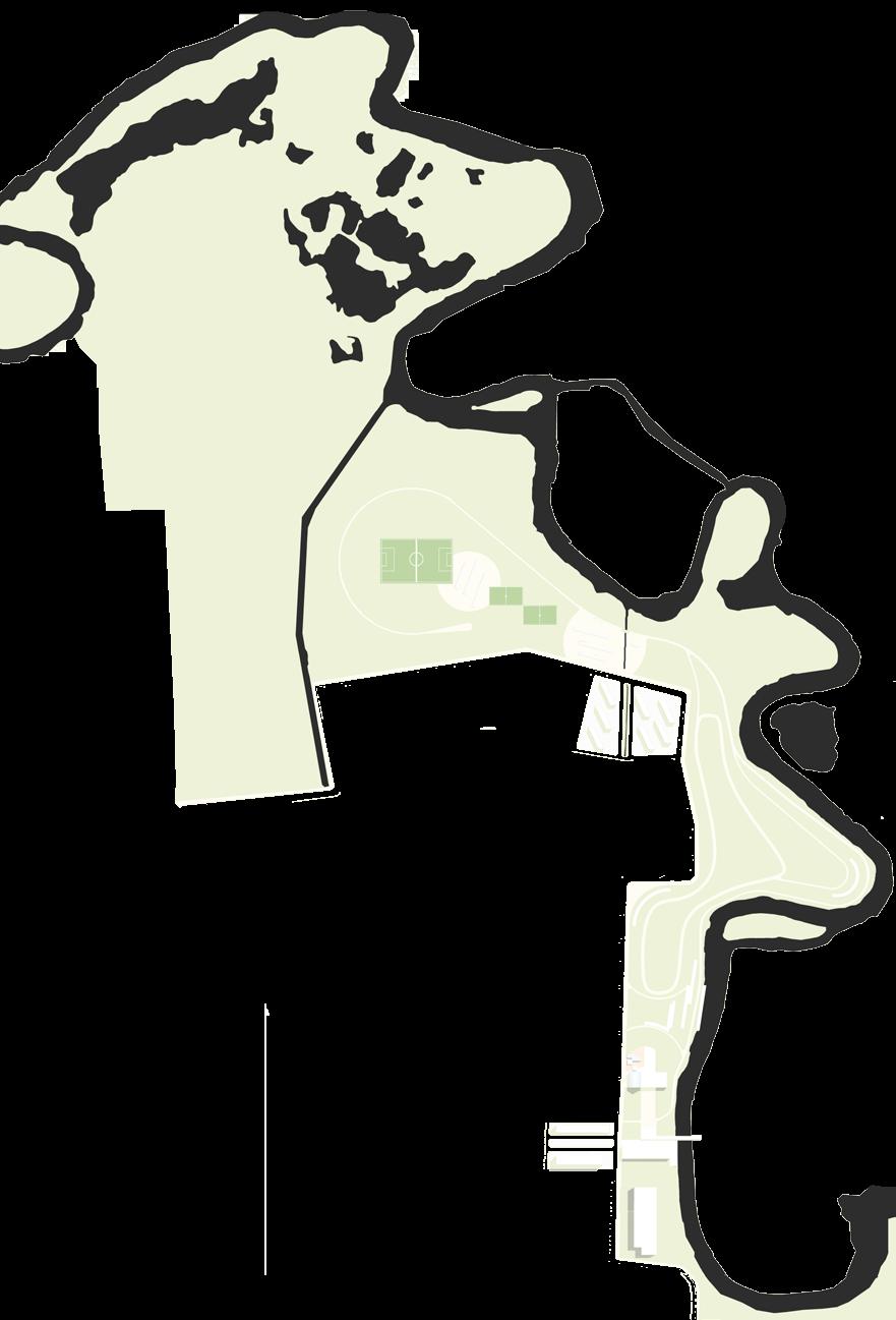
A primeira etapa do Parque Várzeas do Tietê, que está em atuação, é o recorte que engloba desde a Barragem/ Eclusa da Penha até a divisa com São Paulo/Itaquaquecetuba, com boa extensão na região do projeto, Jardim Helena. Nesta região, primeiras ações de desapropriação já entraram em ação em áreas menos ocupadas, afim de estabelecer os primeiros núcleos de lazer do Parque Linear. Aqui, os Núcleos, já instalados, Jardim Helena e Itaim Biacica delimitam a extensão do Projeto desenvolvido, à margem oeste do Rio Tietê.
Barbara Sula Braga
Etapa 1 - Parque
Várzeas do Tietê
Ponto de Wi-fi público
Barreiras físicas e naturais Ocupação irregular
Incentivo ao desenvolvimentoMEM


 Est. Jardim Helena/Vila Mara Est. Itaim Paulista
Rod. Ayrton Senna
Est. Jardim Helena/Vila Mara Est. Itaim Paulista
Rod. Ayrton Senna
Núcleo Itaim Biacica Núcleo Jardim Helena
1 3 4 5 6 7
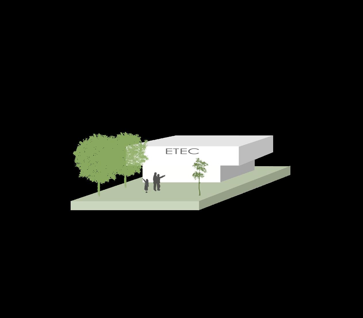
ETEC
Vegetação
Linha CPTM Macroárea de Estr. Metropolit. - MEM Rede Cicloviária Linha de Ônibus
Eixos Previstos ZEUu ZEUa ZEIS 1 ZEIS 2 ZEIS 3 ZEIS 4 ZEIS 5 ZEPEC BIR Esporte Clube da Comunidade Reserva de Mata Atlântica CEU Teatro, Cinema, Espaço de Show Vegetação ESC 1: 30000 Perímetro de Incentivo Incentivo Ed. de Garagem Pressão ocupacional
2 1 2 3 4 5 6 7
Barragem/Eclusa da Penha
Área do Desenvolvimento do Estudo
Recuperação da área de proteção permanente
Preservação e recuperação da mata nativa
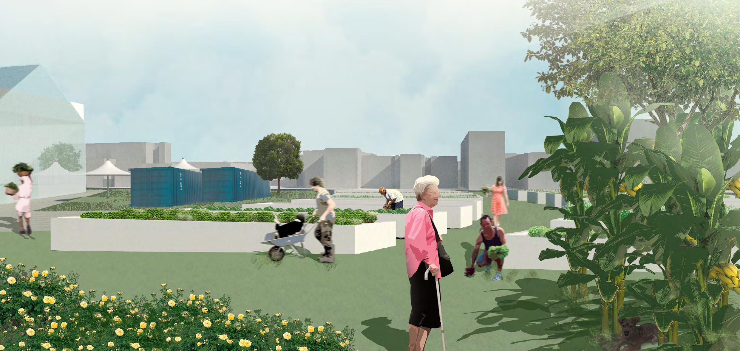
Agricultura urbana orgânica e comunitária
Limpeza de córregos e rios e destinação adequada do esgoto produzido
Equipamento de educação ambiental
Melhoramento e alargamento da via perimetral
Leito do rio normal
N.A. 727m
Cheia do rio - áreas inundadas e encharcadas N.A. 729 m
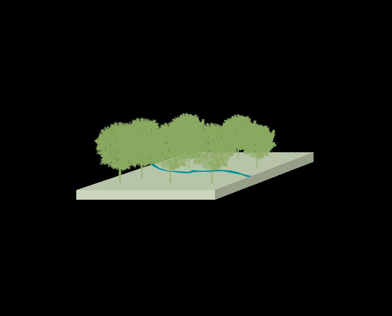
área de proteção total, mata densa
núcleo de esporte e churrasco área de trilha e estar núcleo de equipamentos
s/ escala s/ escala
DIRETRIZES
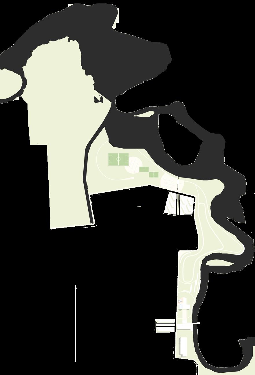
O projeto prevê dois núcleos de HIS - Habitação de Interesse Social, para a realocação de aproximadamente 800 famílias, que foram desapropriadas
Área de preservação e recuperação da mata atlântica, delimitada ao norte e a leste pelo rio Tietê, ao sul pela nova Av. Via Parque e a oeste pelo Núcleo Jd. Helena
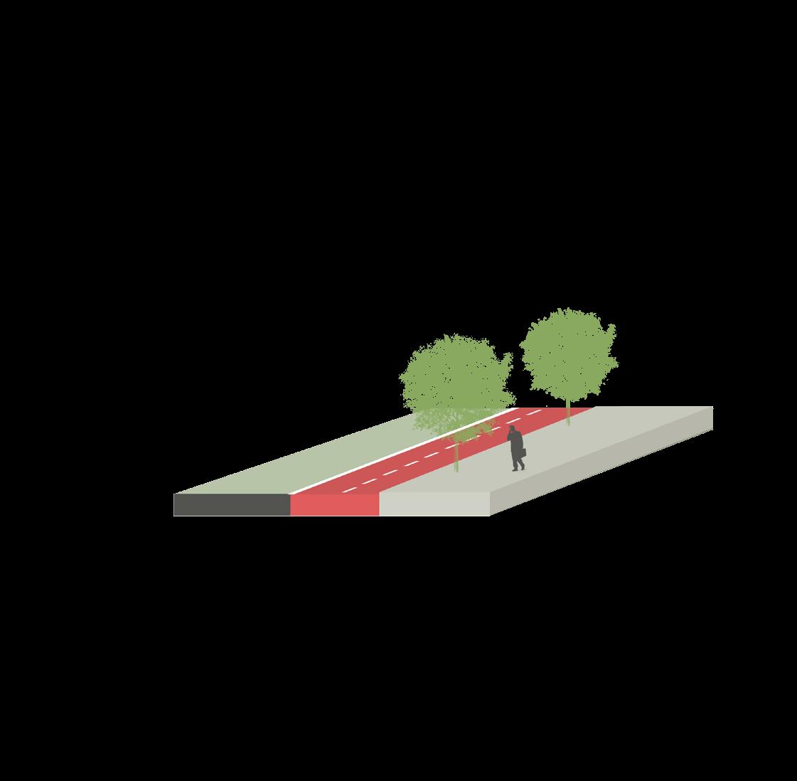
Ciclovia perimetral
a área de preservação da mata atlântica
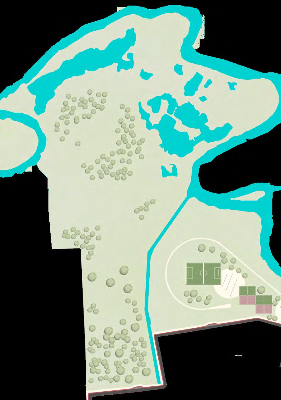
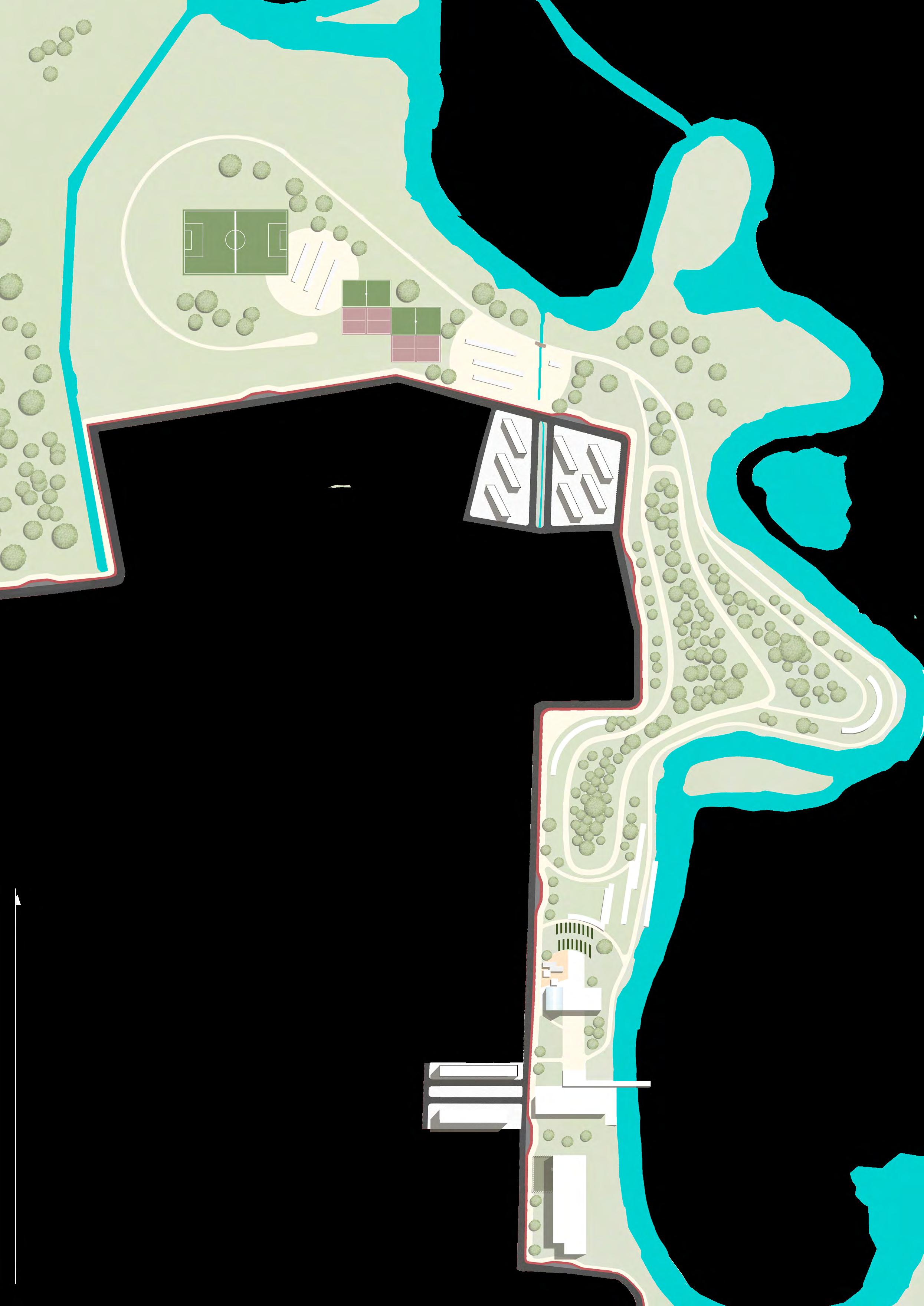
b campo de futebol
c quadras esportivas
d área com permissão para churrasco
e núcleo de agricultura urbana orgânica comunitária
f porto fluvial de passageiros
g escola de educação ambiental
esc 1:6000
HIS HIS b d e f g
a esc 1:10.000
Rua Tietê
via Parque
c
área de feira
horta
galpão de armazenamento e estufa
Núcleo de agricultura urbana orgânica e área de estar
esc 1:3000
 café comunitário

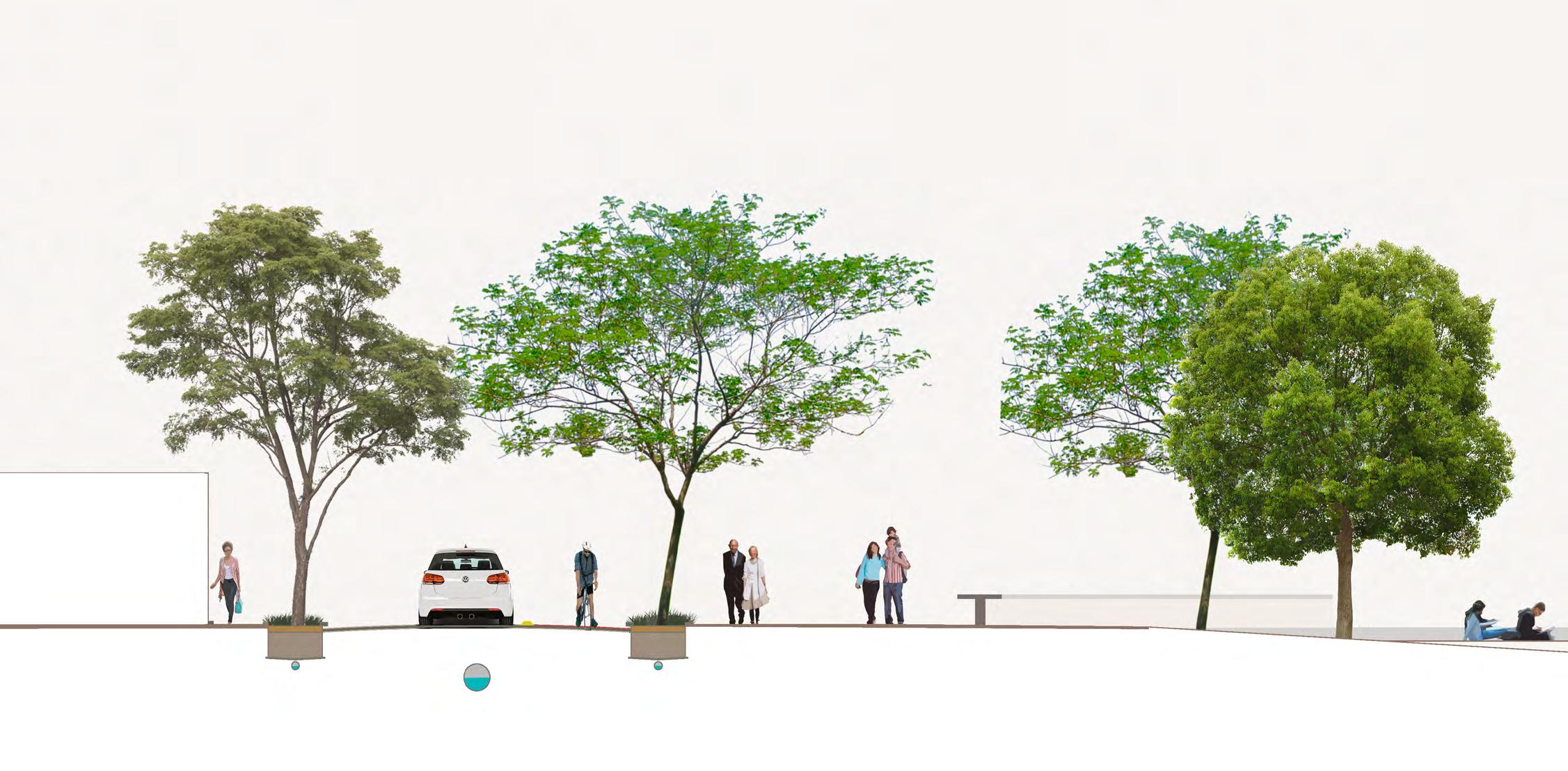
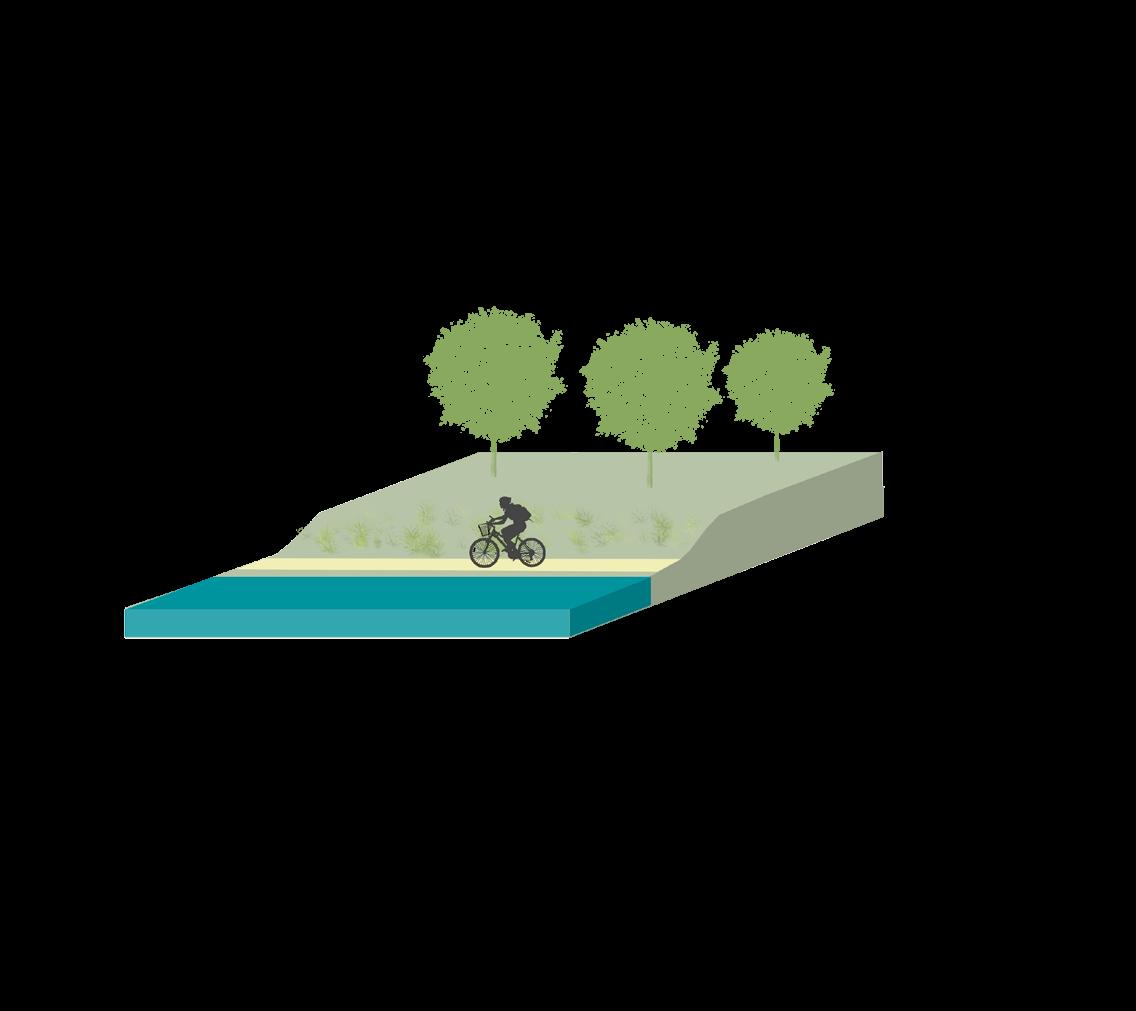
esc 1:250 esc 1:250 A A Corte AA Vias 1,5 1,5 6 2,5 1,5 3,5 9,5 passeio leito carrocável ciclovia calçada perimetral praça esquina drenagem leito e calçada drenagem leito e calçada

esc 1:500 esc 1:250
Ponto de ônibus
Trilhas parque 5 3
5 2,5 área de embarque de ônibus
área de recúo
trilha,
maior intensidade
trilha,
menor intensidade
LISTA DE PROJETOS

CYCLE INFRASTRUCTURE AND THE URBAN GROUND FLOOR
Synergy between high-capacity transport and active modes: implications on the urban ground floor
CYCLE PLAN STRATEGY: SÃO PAULO | Final Essay
CICLOMOBILIDADE | Jaçana - Tremembé
BRT CUIABÁ | 23 Sul
ESTUDO DE IMPLANTAÇÃO DE VLT | EGIS
SERPENTINA | The re-contact with nature
SPINE | Integrating housing in an industrial area
PARQUE DE VÁRZEA JD. HELENA | Recuperação da várzea do Tietê
PORTO FLUVIAL DE PASSAGEROS | Transição e transporte
PORTO FLUVIAL DE PASSAGEIROS
Projeto: Barbara Sula Braga
Orientador: Alexandre Delijaicov
Estúdio de Infraestrutura
FAU USP 2017
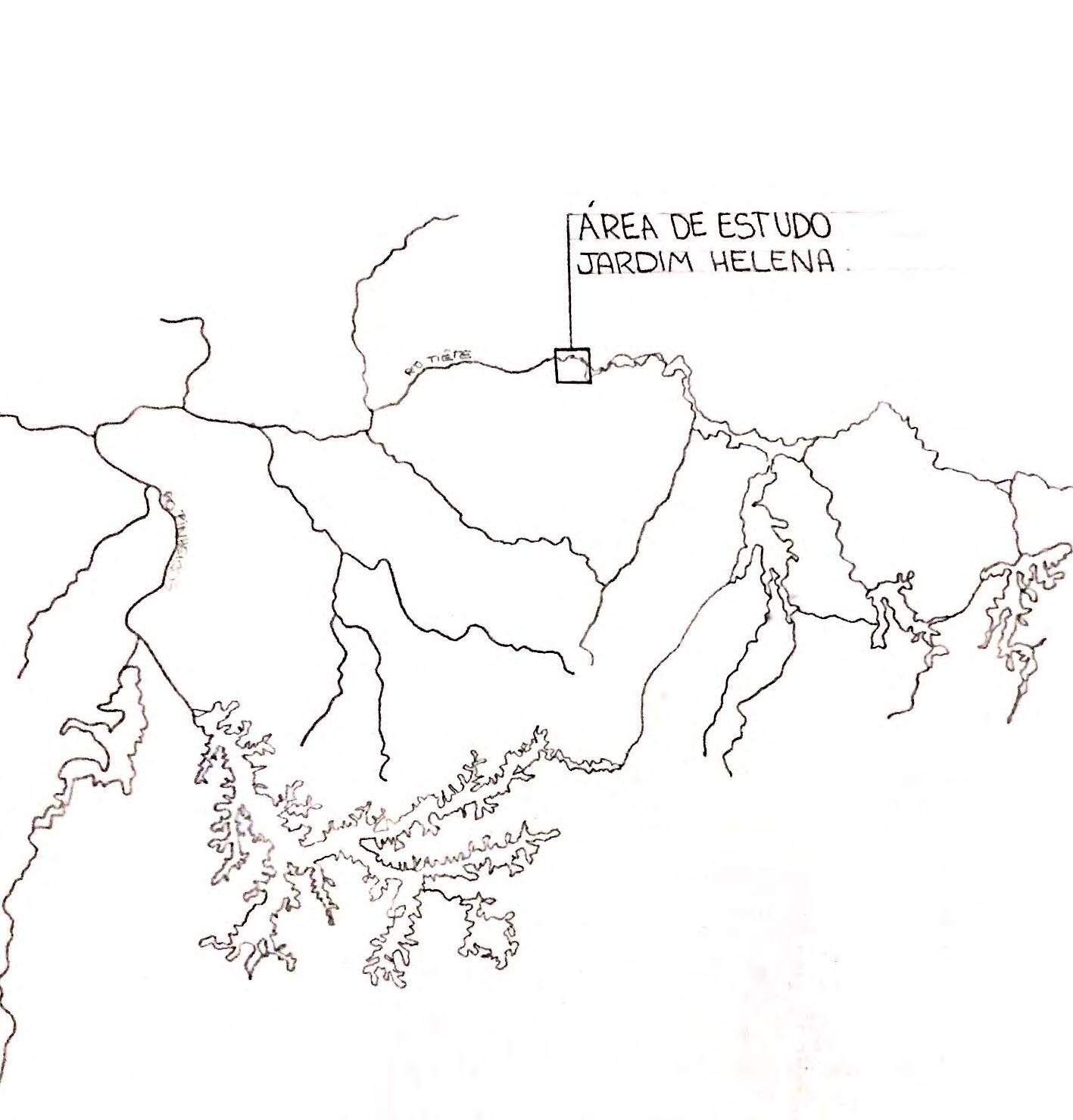
Local: Jardim Helena e Itaim Paulista
São Paulo - SP, Brasil
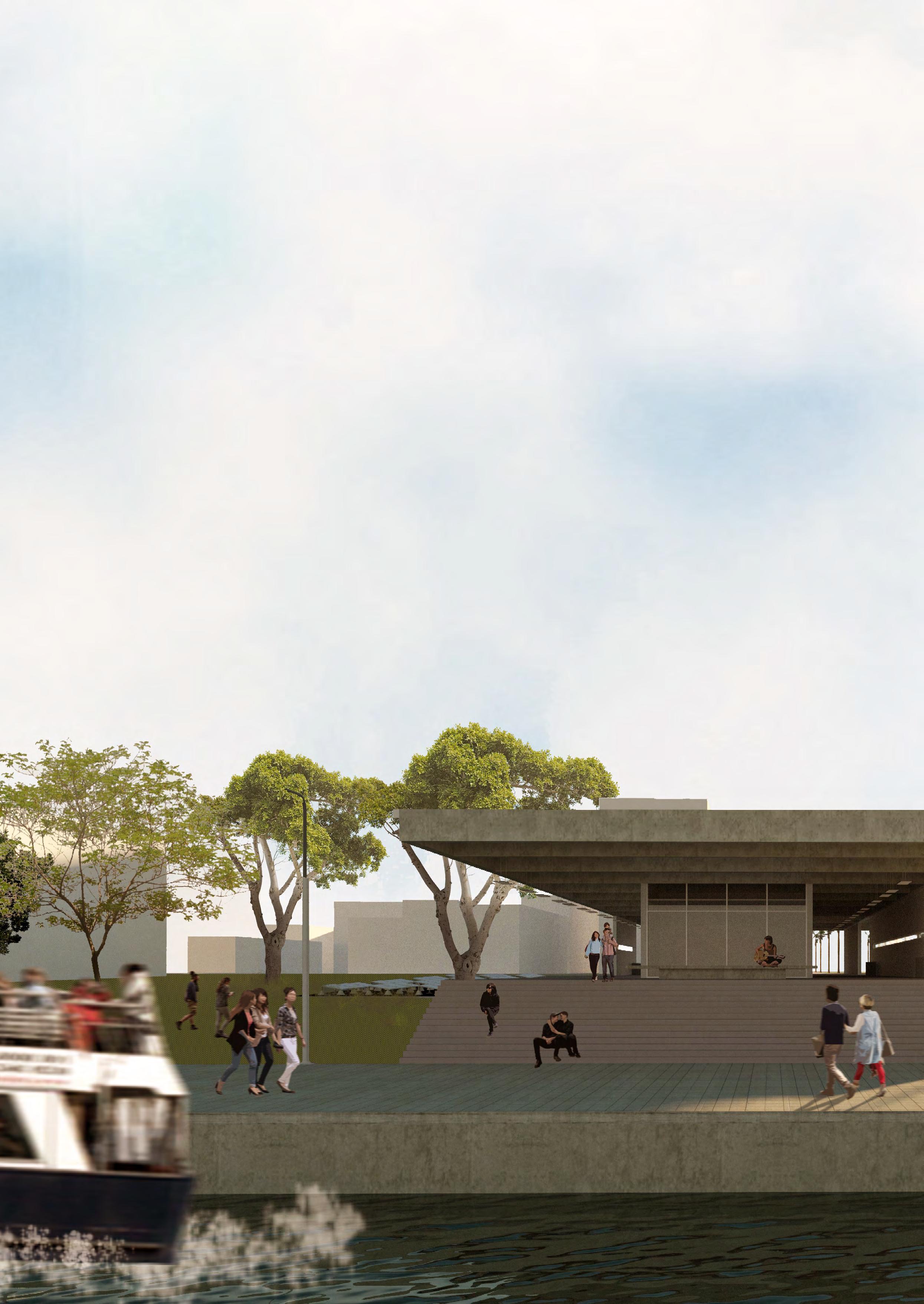
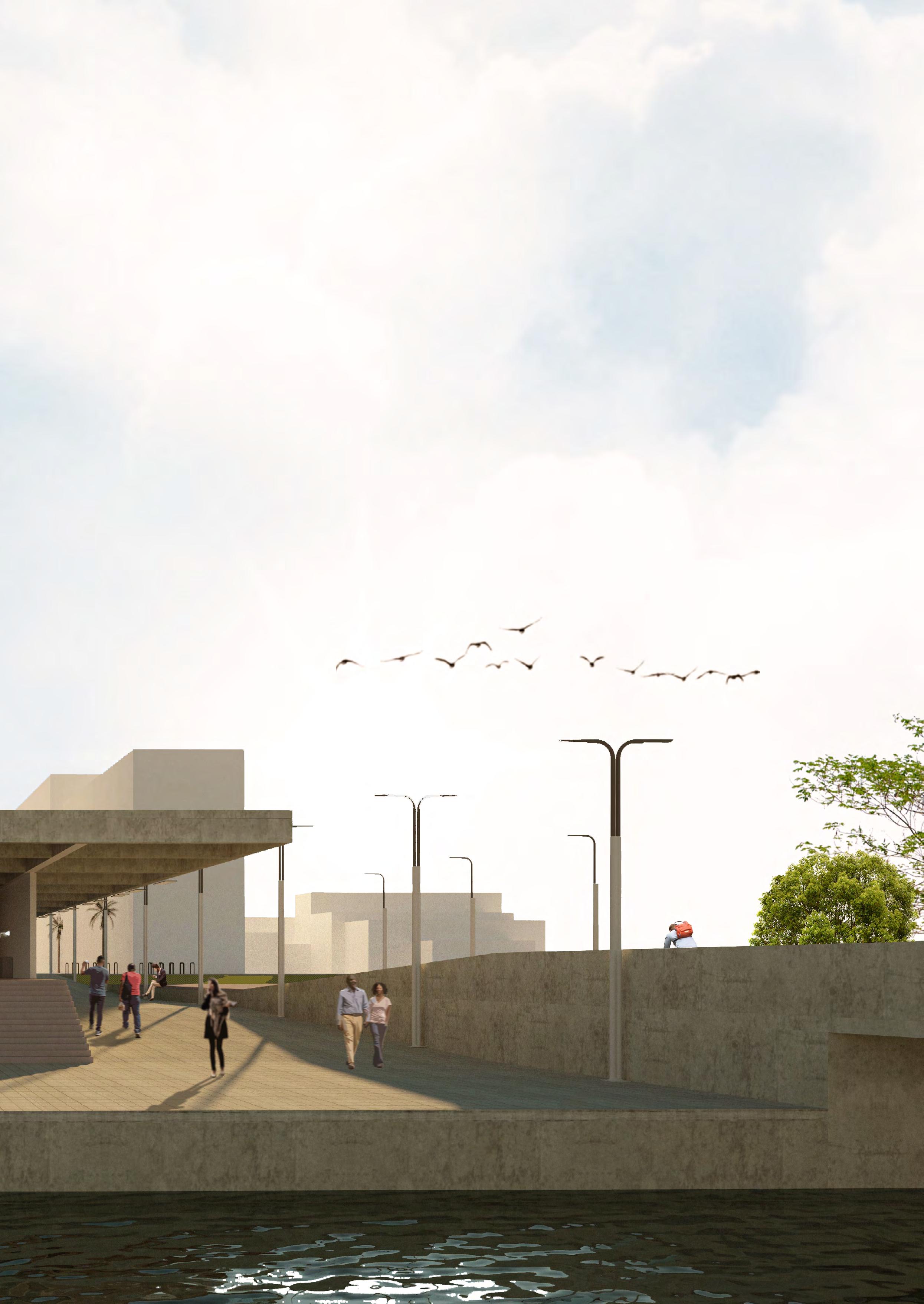
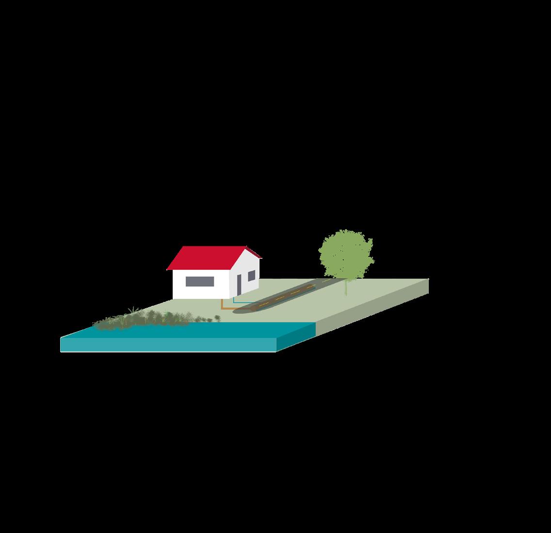
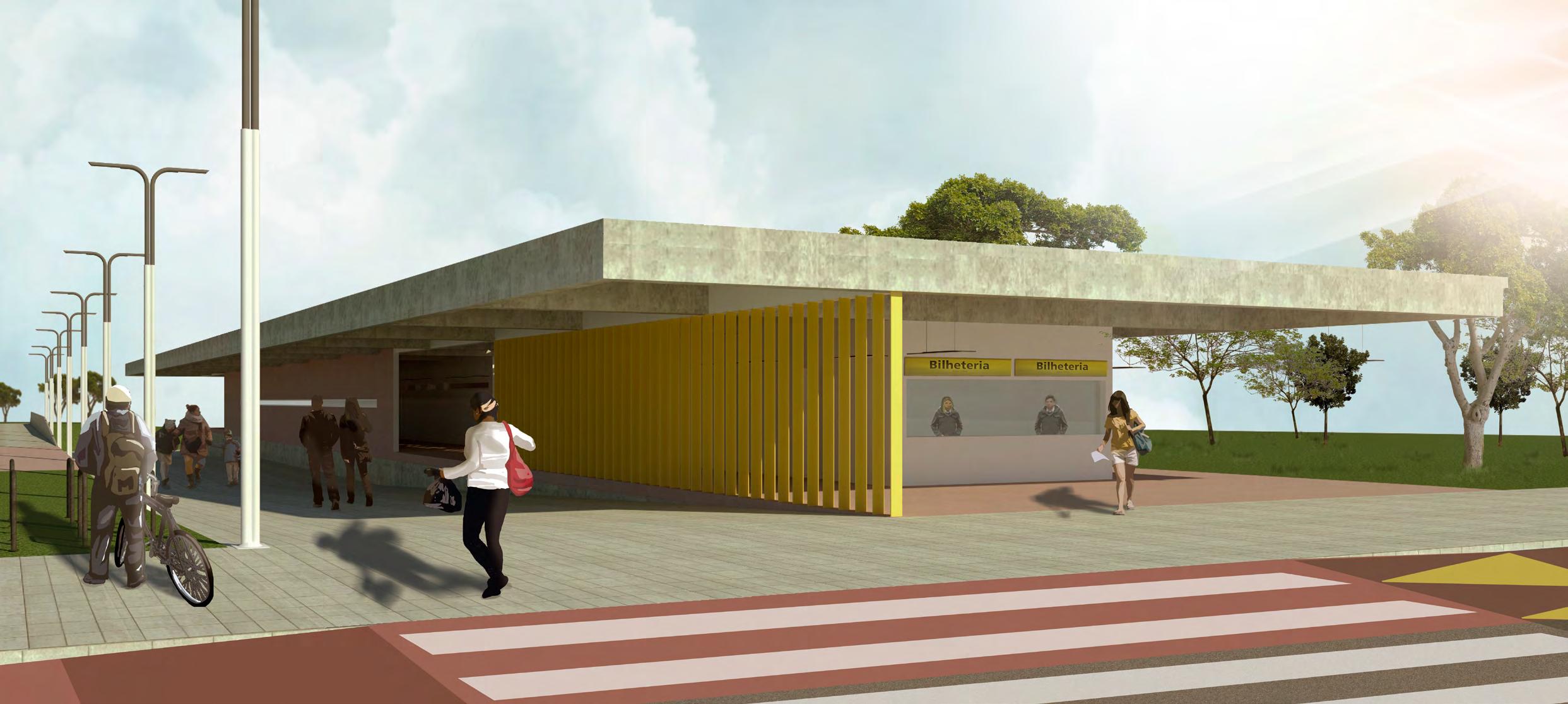
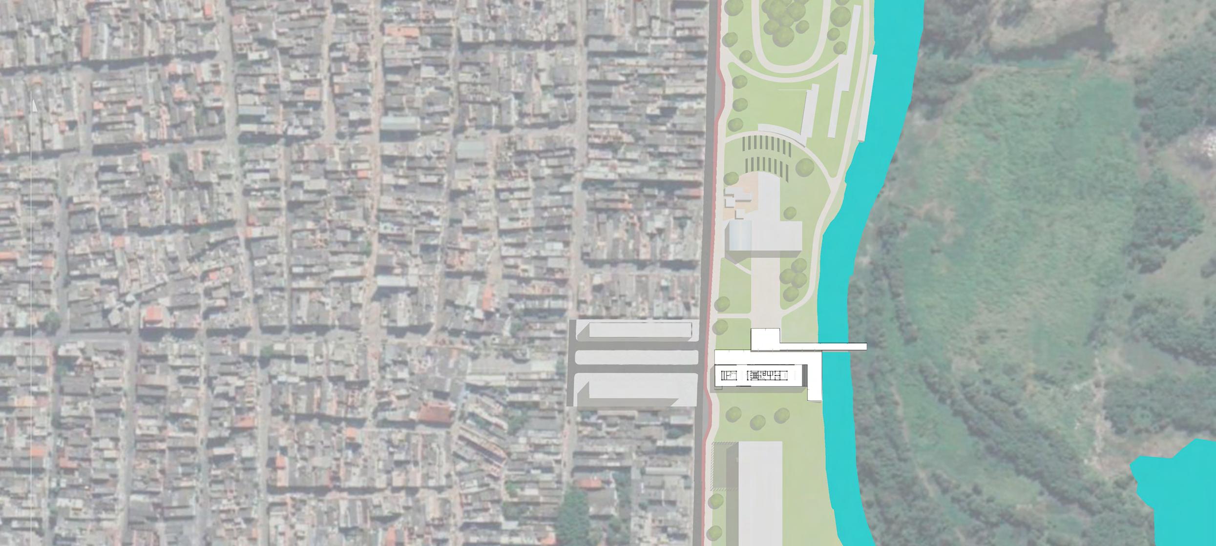
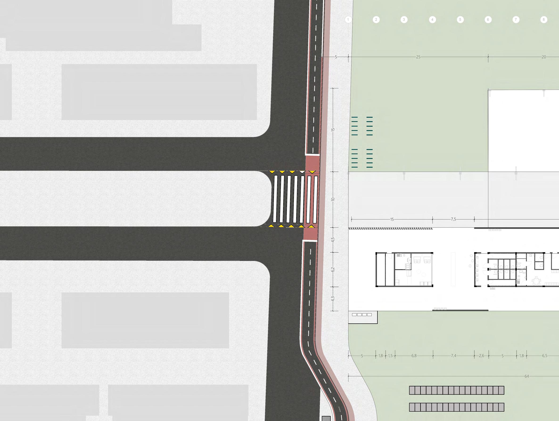
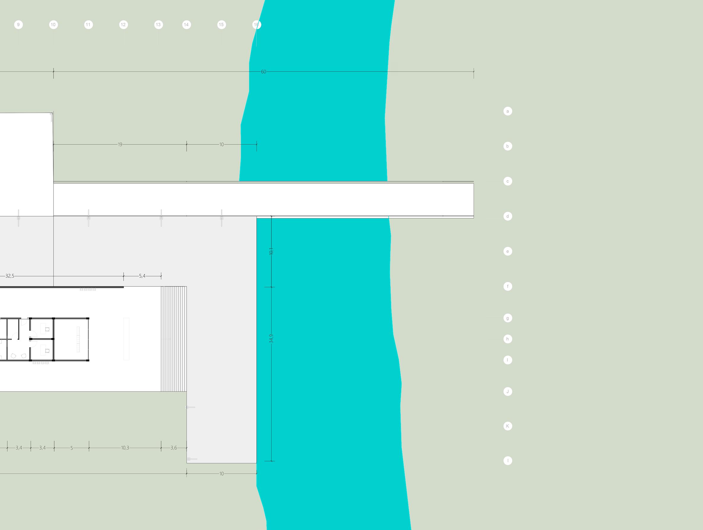
O Projeto do Porto Fluvial de Passageiros no Jardim Helena, Zona Leste de São Paulo, está inserido no Projeto do Parque Várzeas do Tietê, além do Hidroanel Metropolitano de São Paulo. Este último, uma rede navegável que se baseia no conceito do uso múltiplo das águas, inserido em um plano de mobilidade de desenvolvimento urbano sustentável para a cidade. O Projeto prevê o transporte de cargas e pessoas, e sugere um aumento significativo de pessoas na região, promovendo desenvolvimento e sustentabilidade concomitantemente.
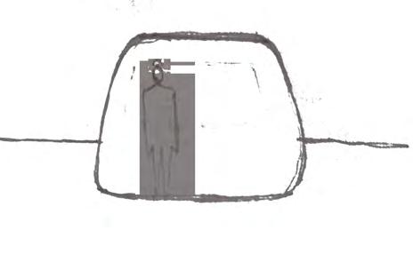
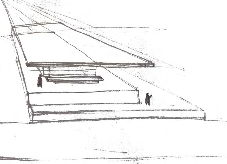
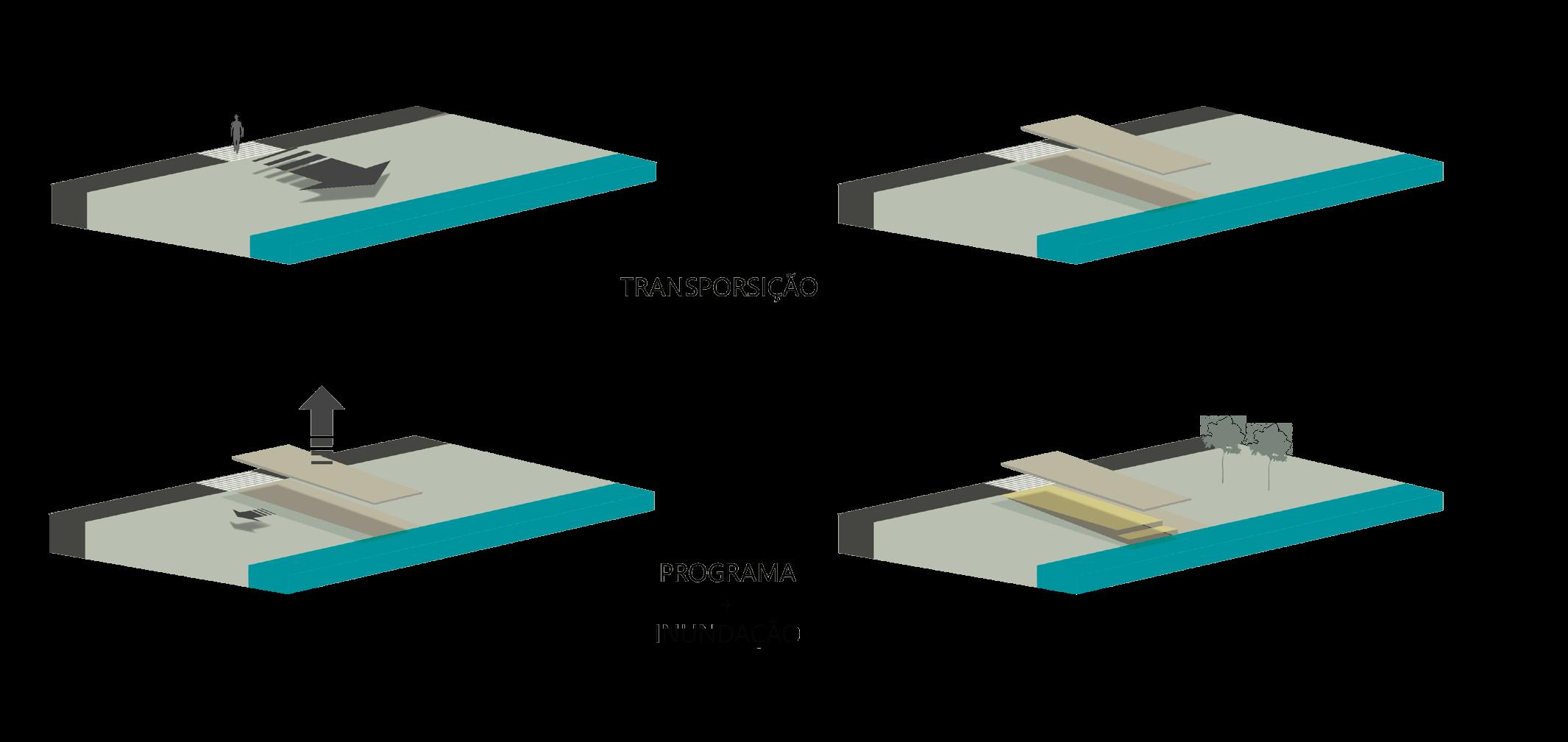
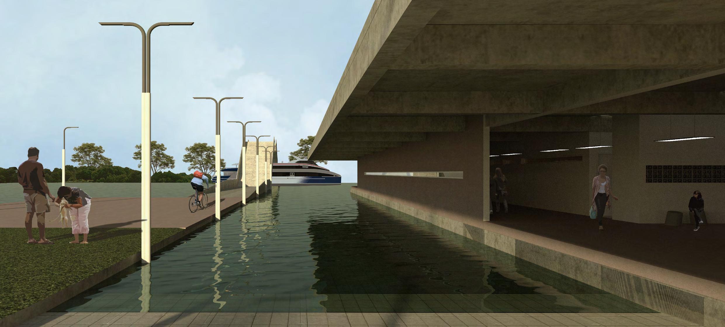
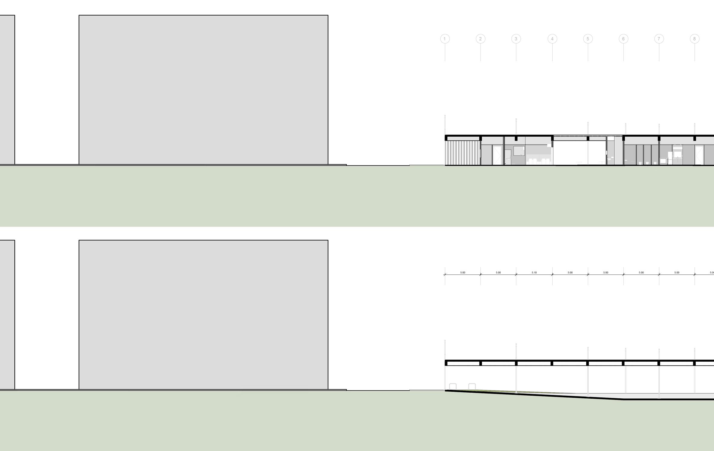
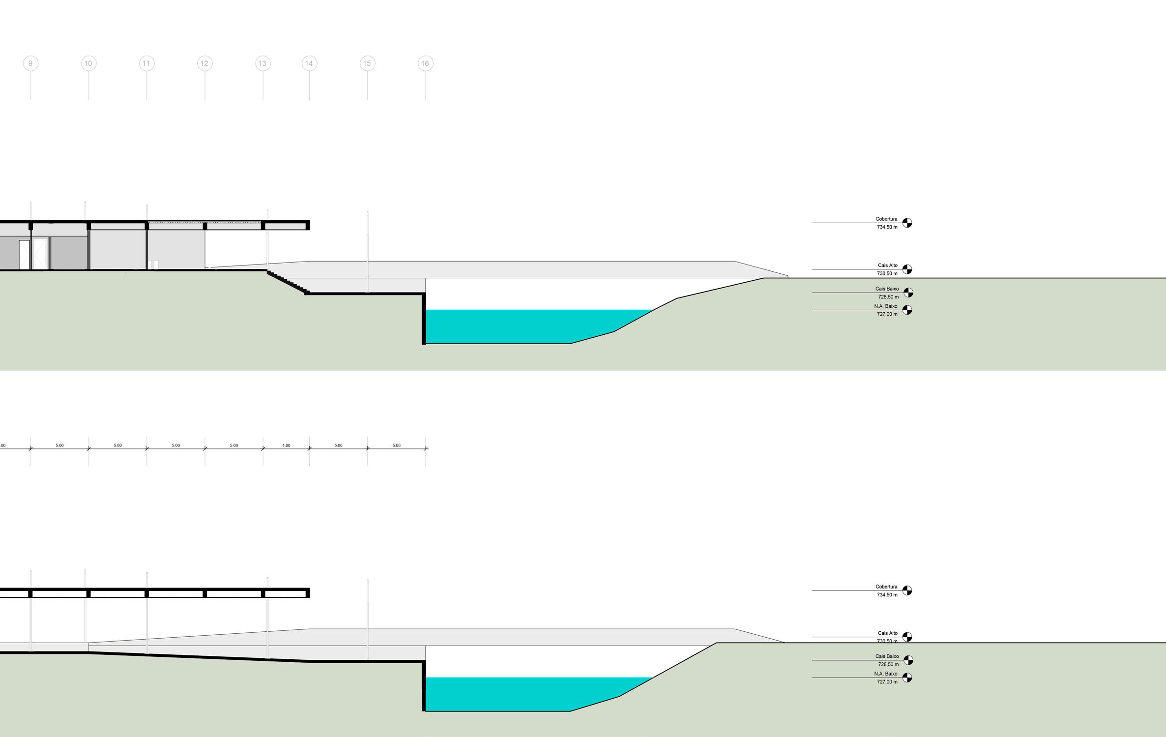
O Porto é uma obra pública e foi projetado com o preceito de ser uma calçada coberta, uma construção simples capaz de atender às necessidades do programa e se adequar as cheias do rio Tietê, valorizando o contato com a água ao passo que evita enchentes. Além de terminal hidroviário, possui uma área de educação que visa a conscientização sobre as águas e várzeas. Seguindo a diretriz sustentável, é equipado com placas solares, que além de promover a conscientização do uso energético, ajuda o abastecimento do edifício.
PROGRAMA + INUNDAÇÃO
 Rua Olivieira Freire
B C B C A A
Rua Tietêvia Parque esc 1:6000 Implantação
TRANSPOSIÇÃO
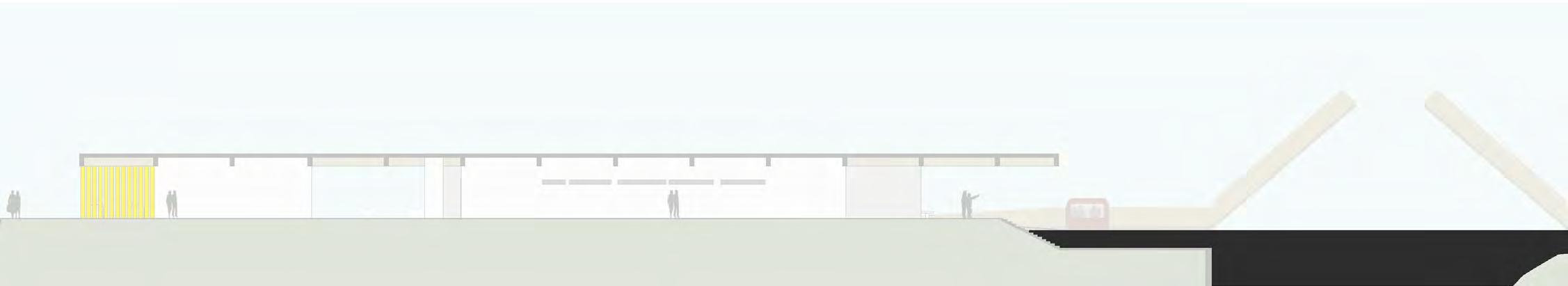

cortes ilustrativos
NÍVEIS DO RIO TIETÊ N.A.
N.A.
N.A.
esc 1:500 Corte AA
s/ escala
727m
729m
730m
Área
instalação
Estudo Solar
para
de painéis solares
8:30 17:30
Estudo Solar s/ escala s/ escala
a b h i j f c d k B C
PROGRAMA
a bilheteria
b café
c sanitários (f/m)
d área servidora adm
- copa
- sanitários (x3)
- área de refeição
- depósito (x2)
- sala adm (x2)
e área de cultura e educação
f área de estar
g cais baixo
h área de estar/ eventos abertos
i bicicletário
j armazenamento resíduos
k placas solares
Planta Baixa
e f g esc
esc
esc 1:500
1:500
1:500
Corte BB Corte CC
B C A A