50 U-BUILD FRAME 2016
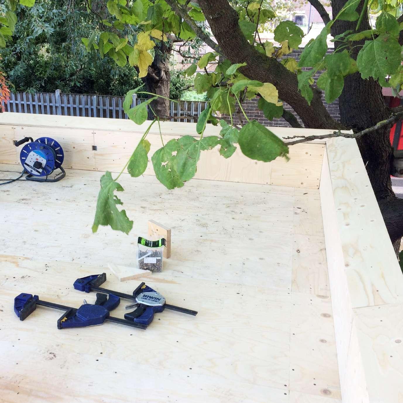
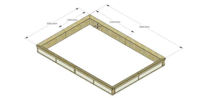
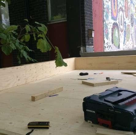
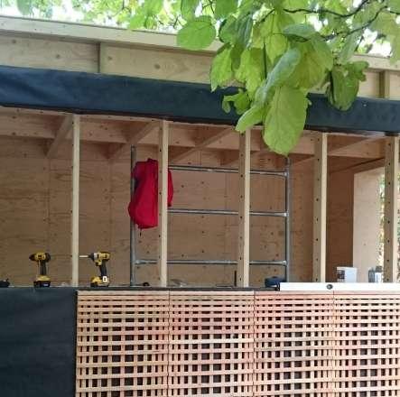
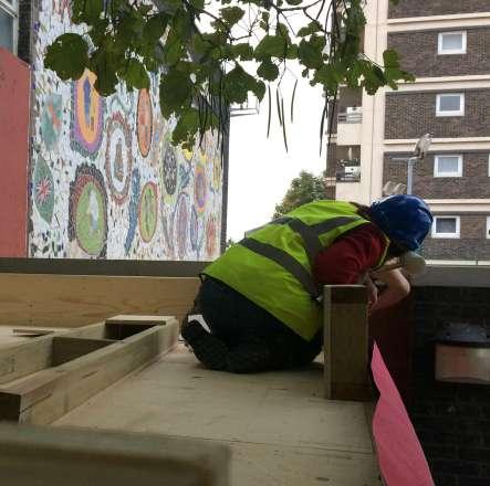
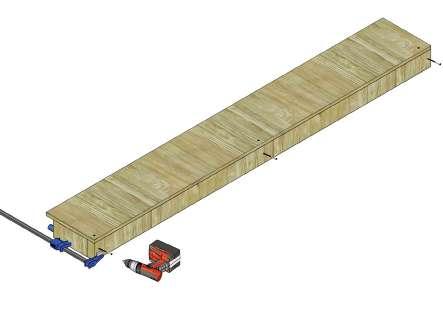
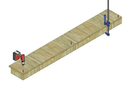
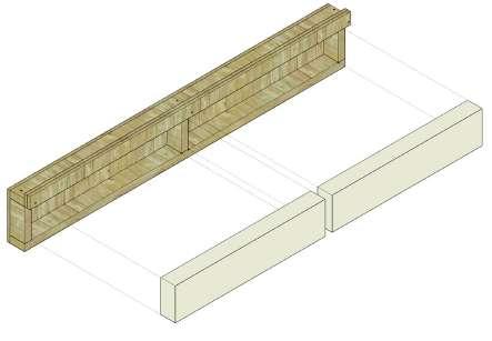
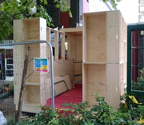
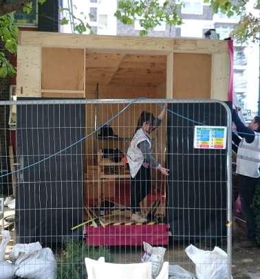
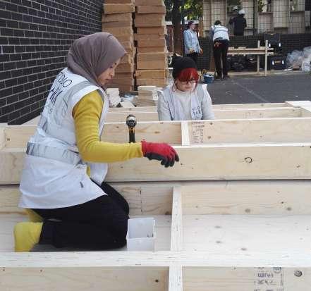
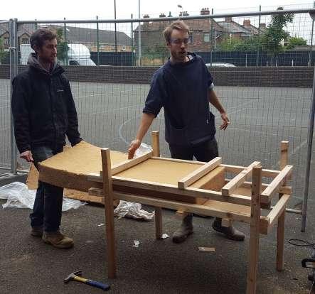
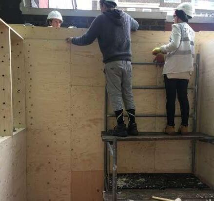
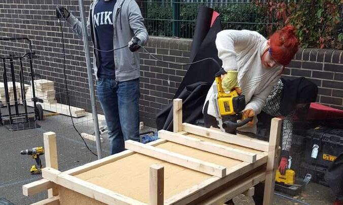
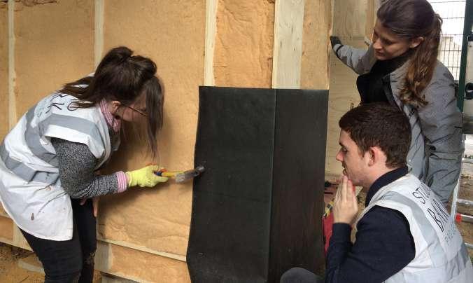
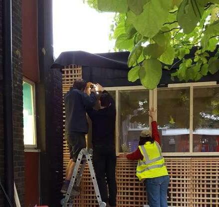
Fig.147 - Parapet installation on site
A parapet is a barrier which looks like an extension of the wall, fencing the edges of a roof. The purpose of a parapet is to act as a low protective wall which reduces the pressure differences at roof edges. There are a few types of parapets which are plain parapets, embattled parapets, perforated parapets and panelled parapets.
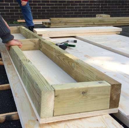
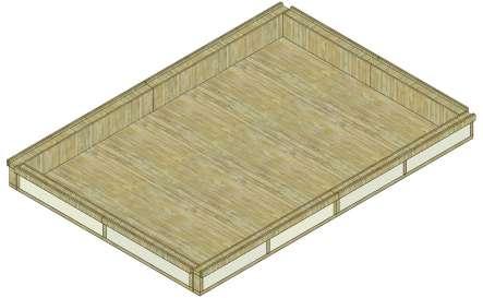
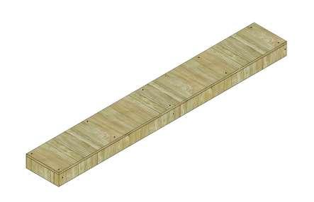
For this project, we used the plain parapet wall by making boxes on site, fixing the box on top of the roof and filling each boxes with insulation which then covered with waterproof membrane. These parapet boxes are later covered by cladding panels on its sides.
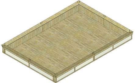
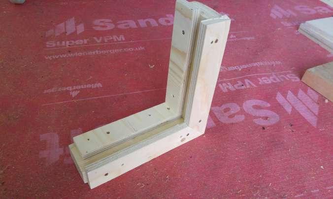
The parapet was an on-site retrofit. The initial design of the parapet is as shown in the first image on the right, a simple wall extension on top of the roof. The initial dimensions of the parapet, which
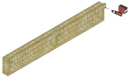
was cut by CNC, was a failure as the sizes were smaller. Therefore, the team decided to design a new parapet and it was discussed on site using the off cuts of plywood. The design of the new parapet was sketched by Nick from Studio Bark, as shown in the image below.
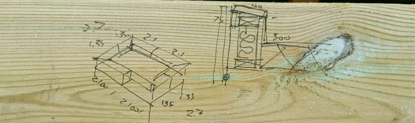
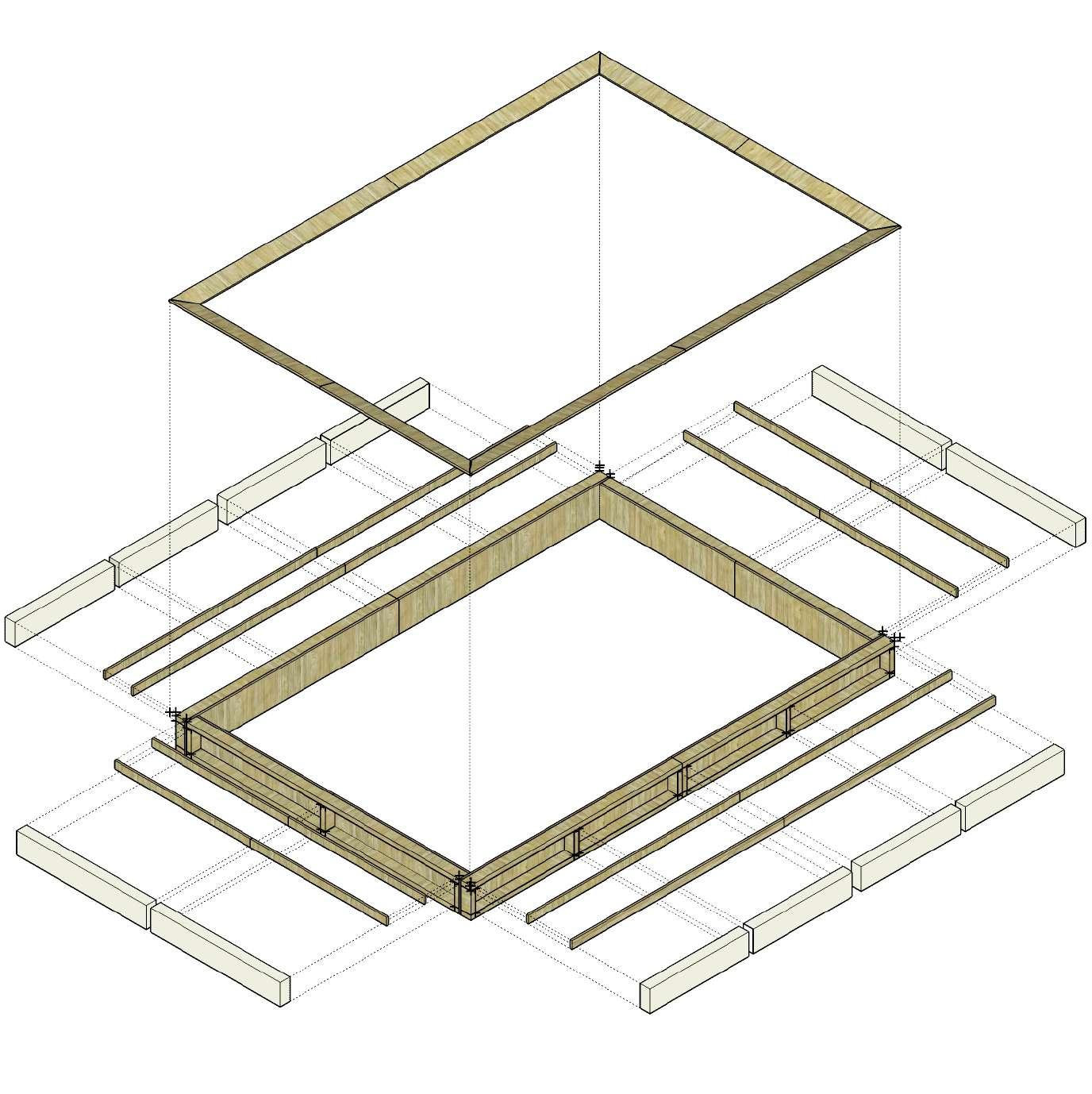
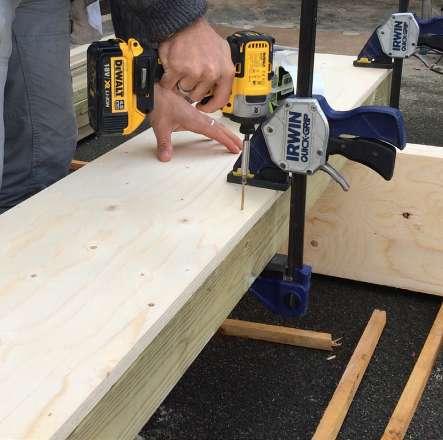
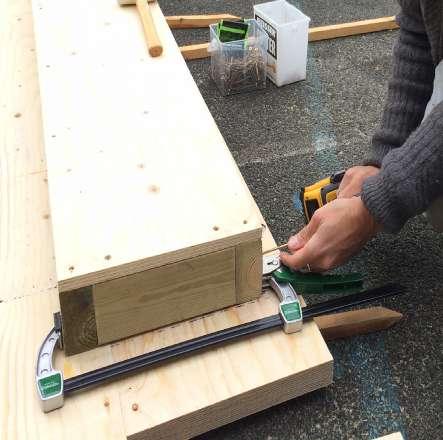
The main elements of the parapet are the parapet boxes, insulation and waterproof membrane. The principle of making the parapet to work correctly is to slope the top of the parapet inward so that they don’t stain the building’s facade. This is the main purpose of the piece of plywood that was installed on top of the boxes, which is then covered by a waterproof membrane under its coping. The workmanship for the parapet is always kept as defined when making and fixing it to the roof to ensure good air tightness.

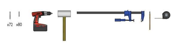
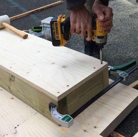
TOOLS USED
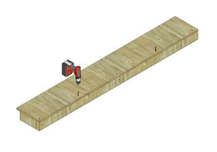
Take
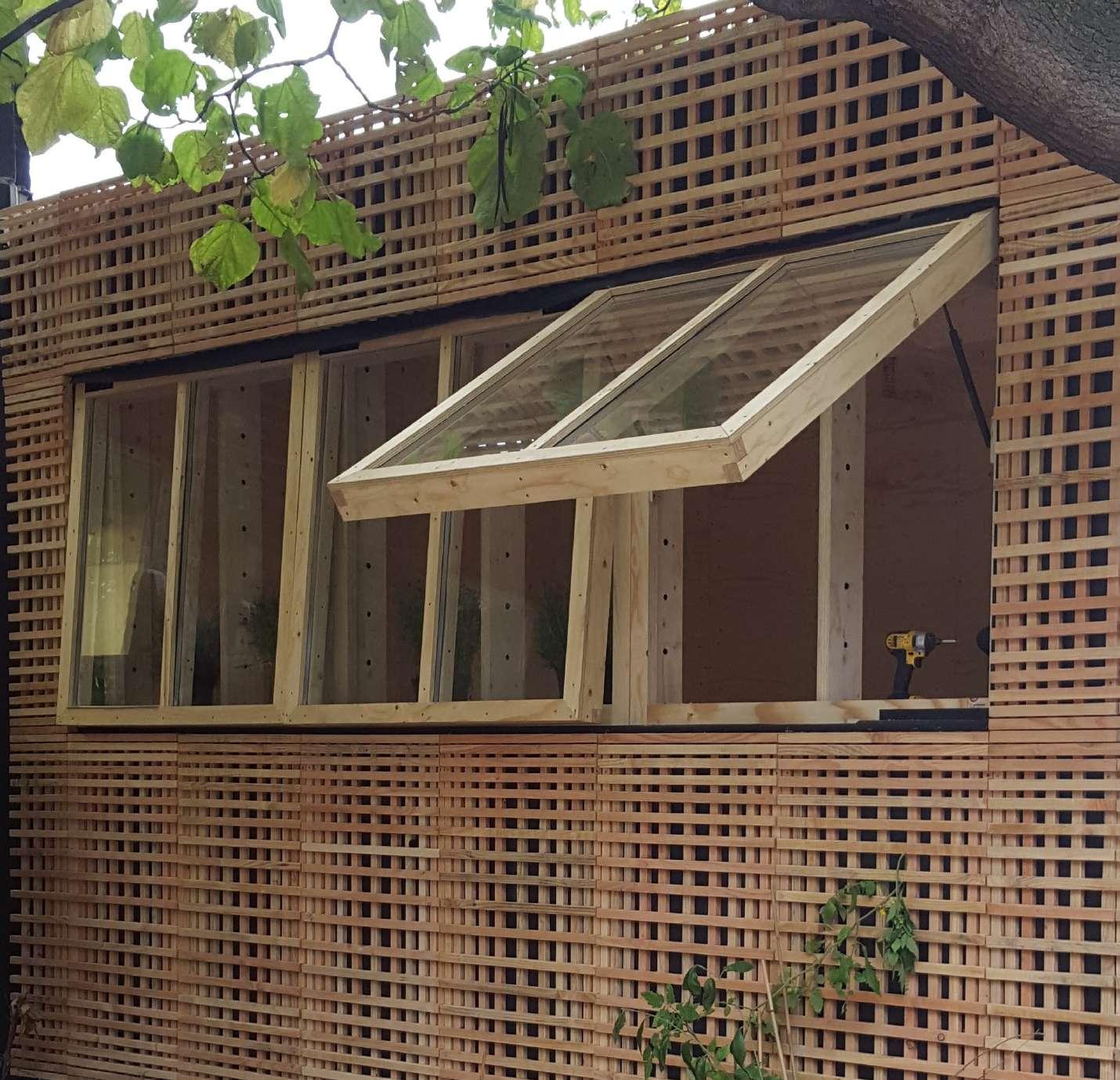
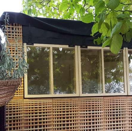
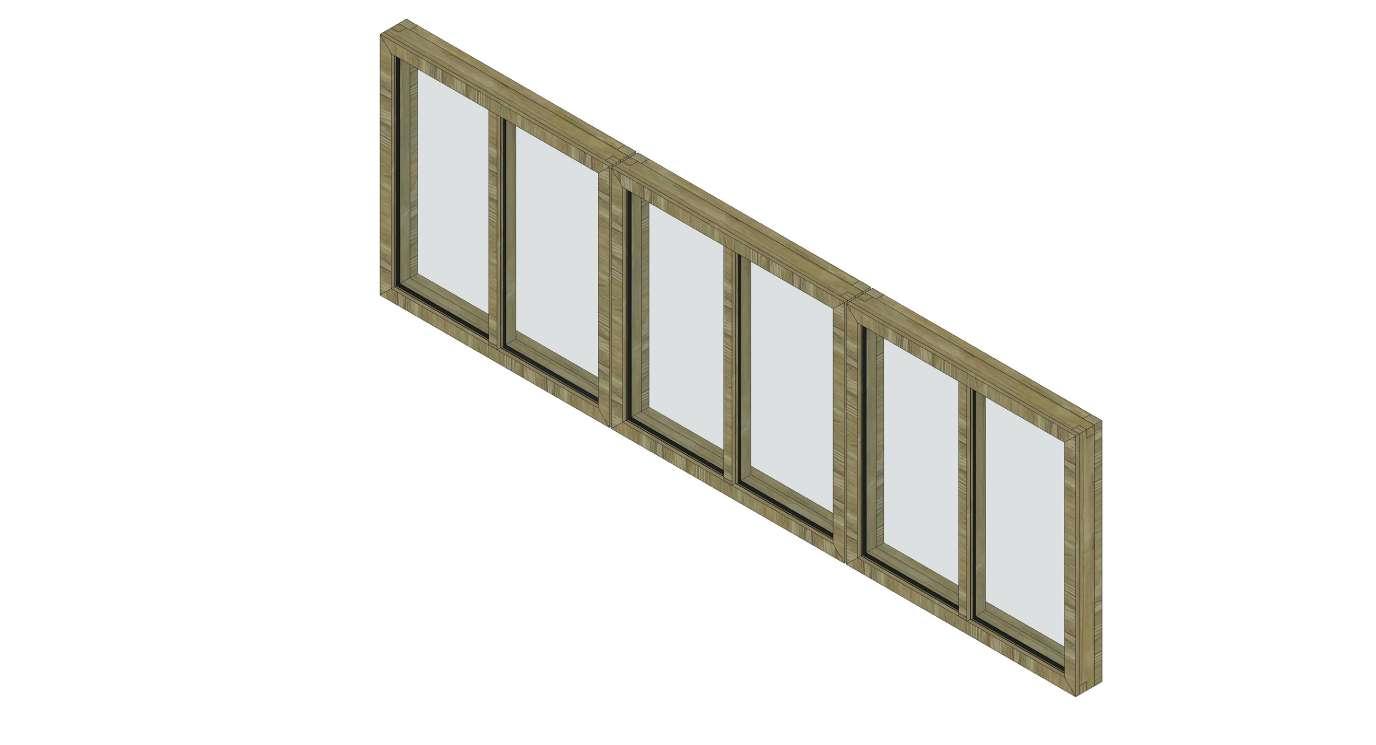
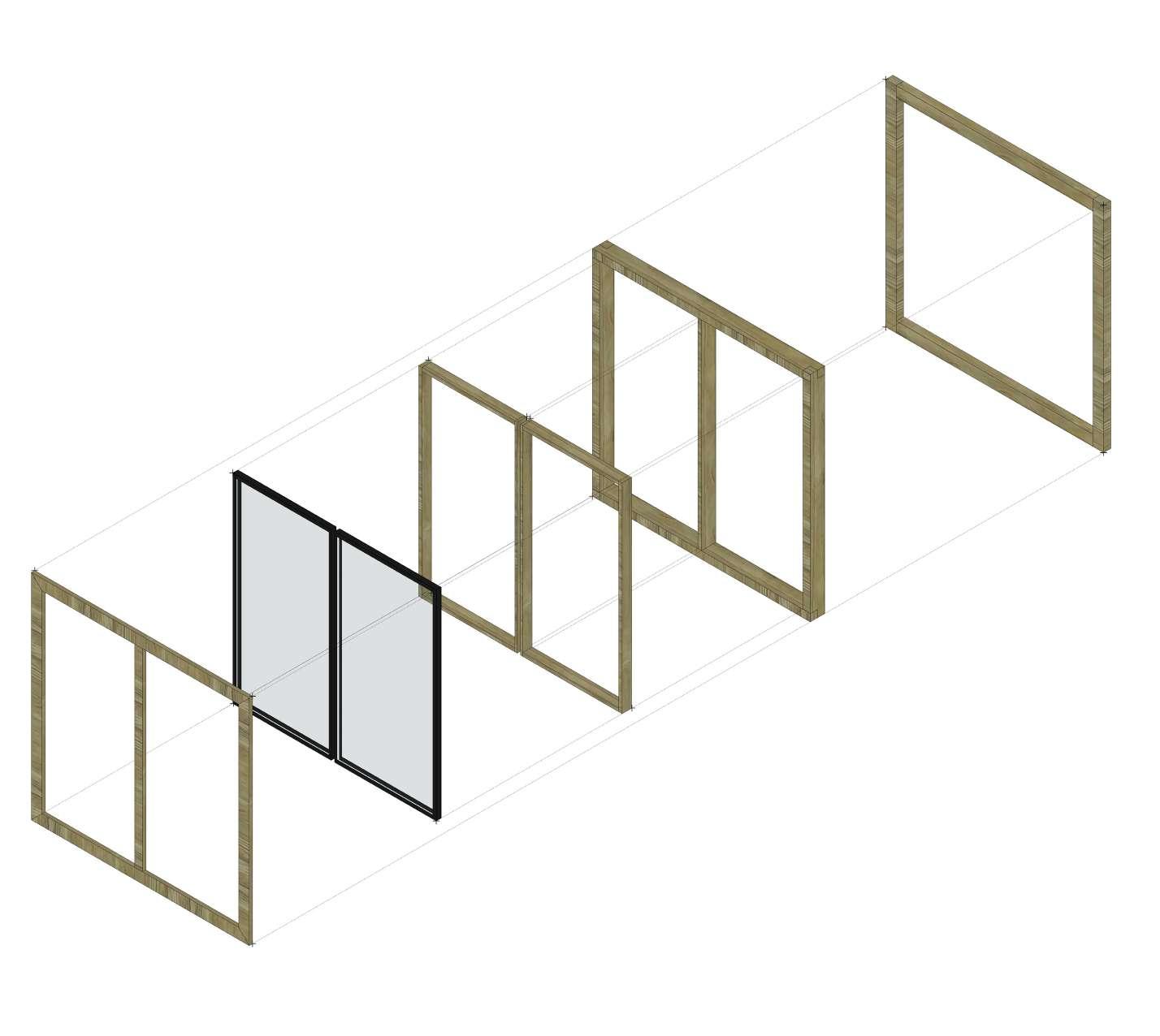
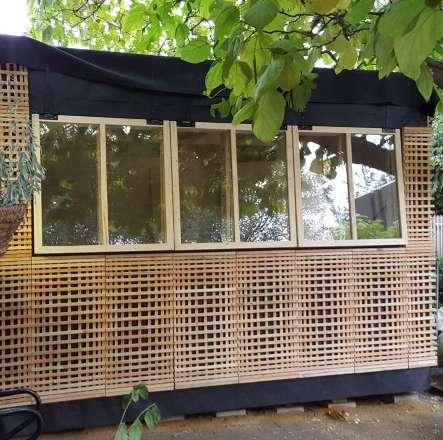
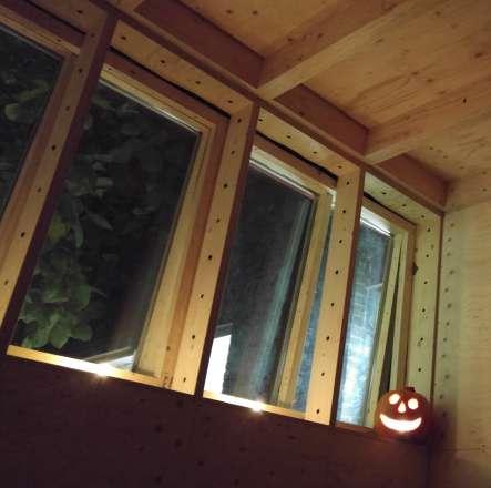
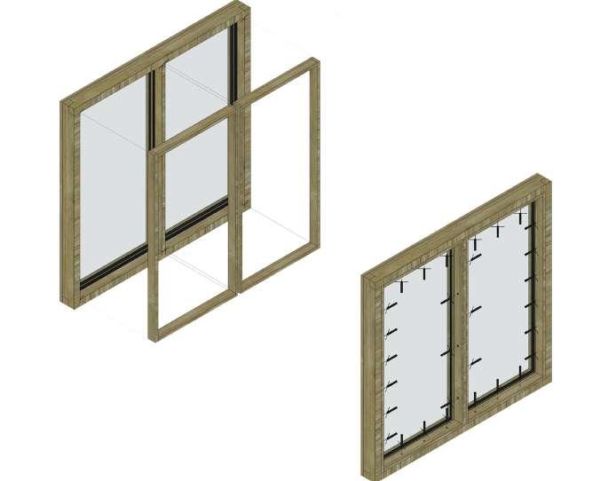
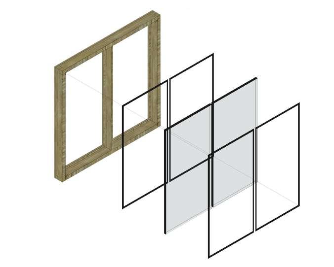
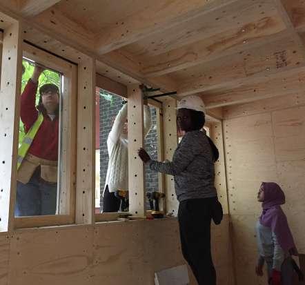
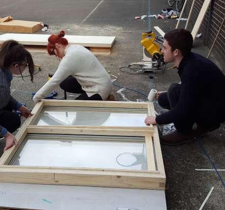
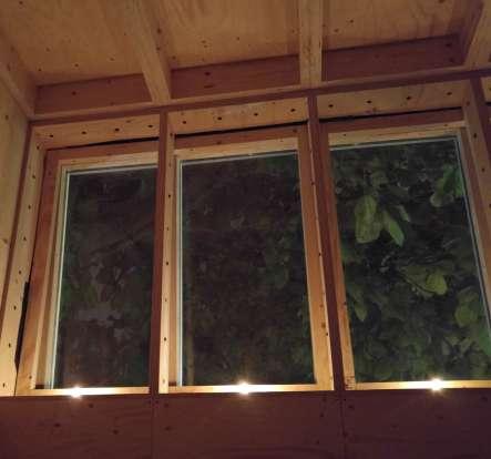
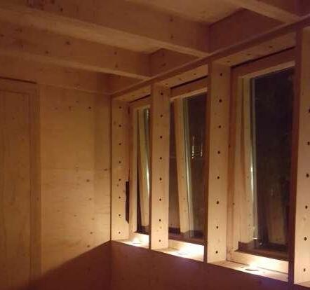
In the structure there are three windows - two side windows W1, which are mirrored versions of each other and consist of the same parts, and one window W2, which is in the middle. Windows size allows for 5mm tolerance all around each of them. Windows were designed to match the divisions of the structure. Therefore each is divided with a mullion to match window boxes behind. Windows W1 require two pieces of glazing G1 and G2 as the mullion is positioned to match the window boxes rather than in the centre of the window. Window W2 requires two pieces of glazing G1 as this window is symmetrical.
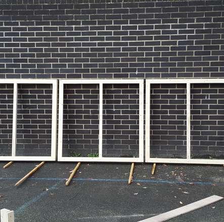
When designing windows we allowed 5mm tollerance all around each window. It proved to be usefull as the frames turned out to be slightly larger due to us hand-cutting the pieces.
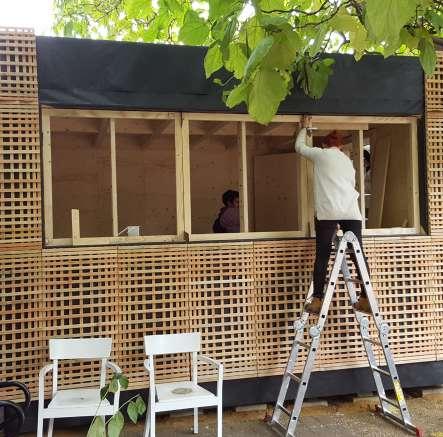
Fixed frame is attached to the window boxes. Due to the design
sash has been attached with gate hinges to the beam on top of window boxes. Therefore the cladding can go down almost to the edge of the window.
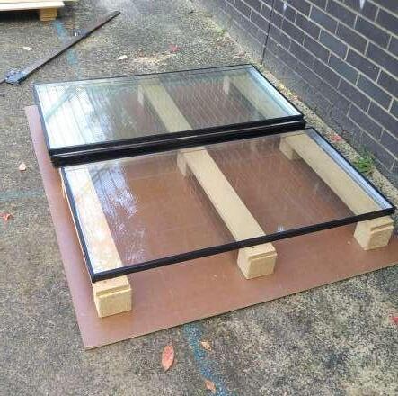
Glazing was allowed very little tollerance, together with foam insulation it fitted very tightly into the frame.
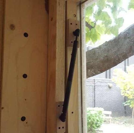
Windows are held open by car boot pistons, latches have been designed to keep them closed.
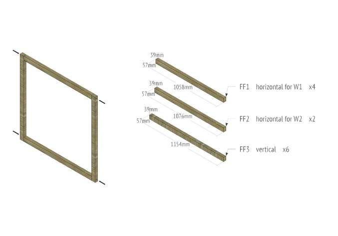
FIXED FRAME FRAME
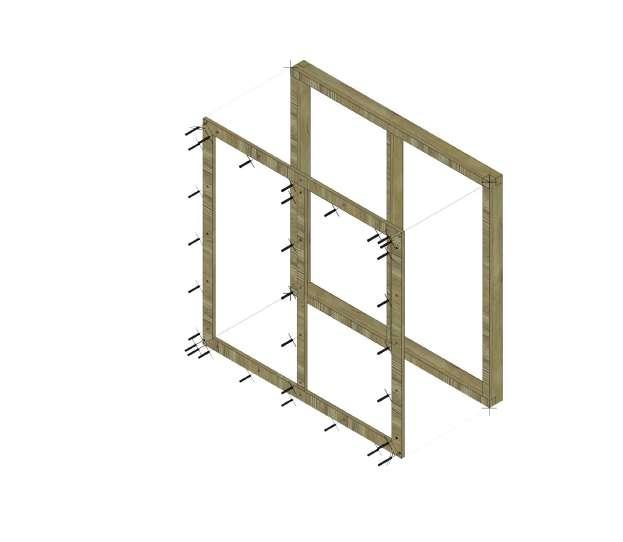
FIXED FRAME It is the fixed part of the window. It is made out of 57mm x 39mm parts of kerto. Parts are joined by butt joints and screwed together. Each FIXED FRAME consists of two horizontal parts FF1/FF2 and two vertical parts FF3.
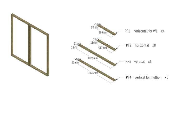
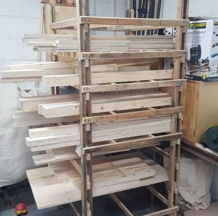
PLYWOOD FRAME
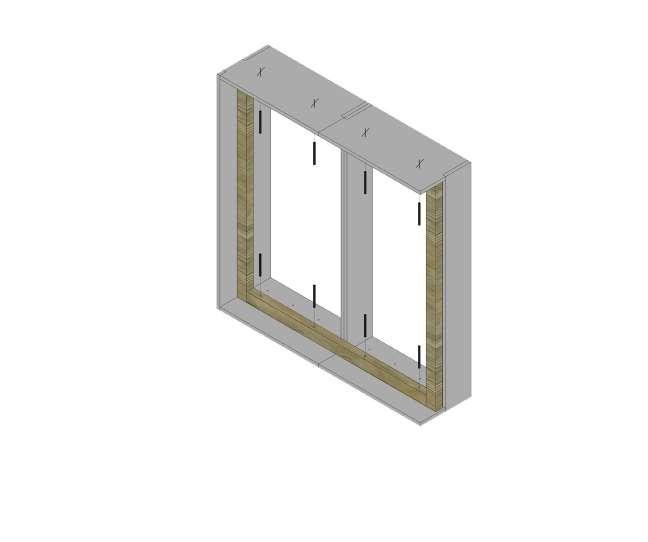
PLYWOOD FRAME It is a part of window structure that holds the glazing in place. It is made out of 51mm x 18mm and 51mm x 12mm parts of plywood. Parts connect by butt joints, they are not fixed one to another. Each window PLYWOOD FRAME consists of two horizontal parts PF1 (used only for window W1)/PF2, one vertical PF3 and one mullion PF4 per each glazing.
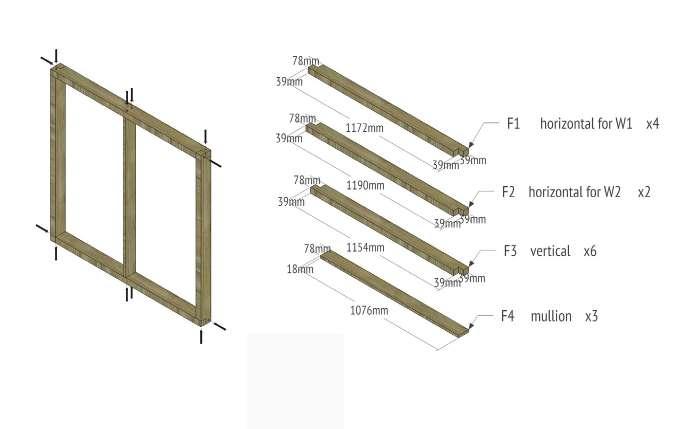
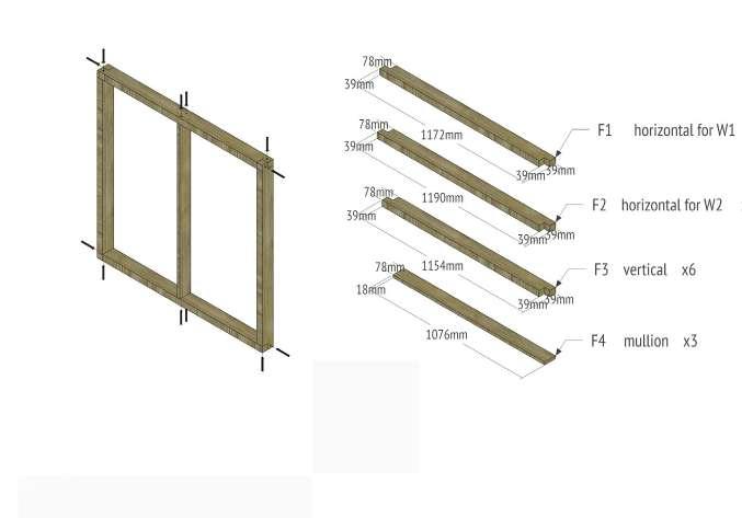
FRAME It is the structural part of the window. It is made out of 78mm x 39mm parts of kerto with 18mm x 78mm plywood mullion. Kerto parts are joined by halved joints and screwed together. Mullion is screwed to the horizontal pieces. Each window FRAME consists of two horizontal parts F1/F2, two vertical F3, and one mullion F4.
FACE It is the external part of the window. It holds the glazing in place. It is made out of 57mm x 18mm and 42mm x 18mm parts of plywood. Parts connect by miter joints, they are not fixed one to another.
Each window FACE consists of two horizontal parts FA1 (used for window W1)/ FA2 (used for window W2), two vertical parts FA3 and one mullion FA4.
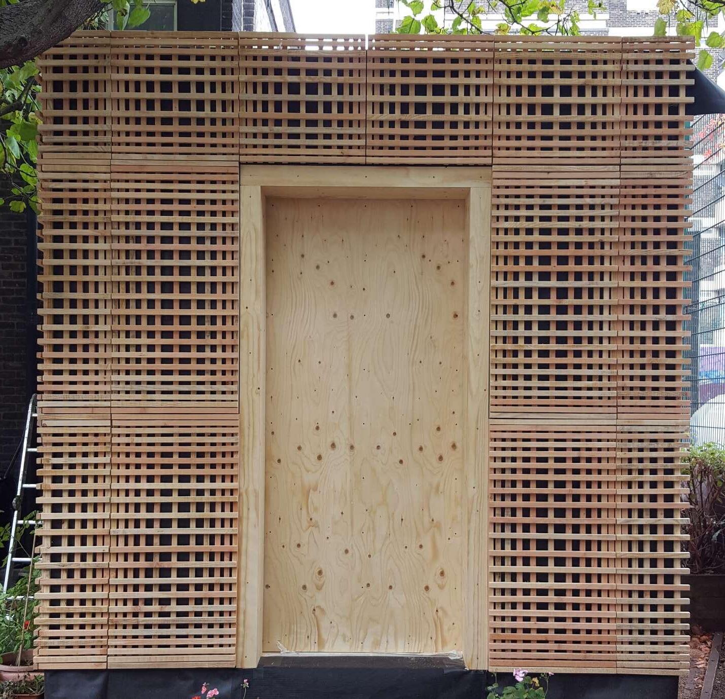
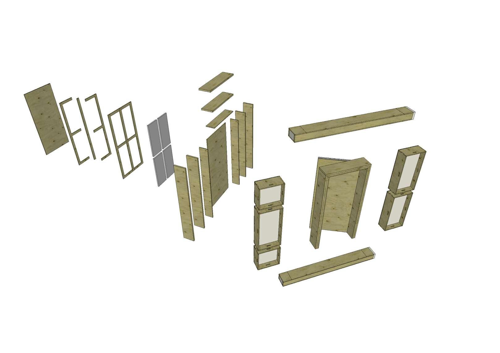
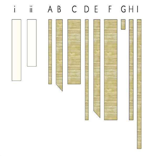
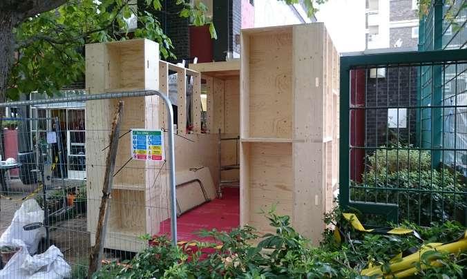
The door is located on the side of the room facing the church. It is a large opening measuring to 2400mm x 1200mm. The opening is formed as a result of the stacking of the wall boxes on either side which alternate in size and the floor and ceiling boxes above and below. The door is therefore the same height as the internal floor to ceiling measurement.
Firstly the frame of the door is built up using lenghts of 2361mm x 320mm x 39.5mm vertically with a piece of 1200mm x 320mm x 39.5mm kerto horizontally at the top. These are fixed with external grade wood screws. This creates the first layer of door frame which sits tightly within the opening. It is important to make sure the timber is the correct lengths to ensure that there are no air gaps around the edges. Then the second layer of door frame is put on using two lengths of 2322mm x 320mm x 39.5mm vertical kertos and a 1125mm x 320mm x 39.5mm horizontal piece. These two layers create the basic frame onto which the door leaf will be hung
using hinges. Again it is important to make sure that the pieces are the correct length and are very tightly screwed into each other.
The door leaf is also layered with 4 layers of plywood and insulation in between. The leaf will be 1033mm x 2312mm exactly in order to have a 5mm tolerance around the edge in order to be able to open it. The layers are broken down into two solid pieces of plywood for the internal and external faces with two layers of frame pieces on the inside which will enclose the insulation and provide rigidity to the leaf. These layers are held together using wood glue and screws carefully positioned not to clash with each other.
Finally 3 pieces of plywood are screwed into the door frame to act as door stops and the door is hung using hinges which have been chisled into the leaf and frame and screwed in.
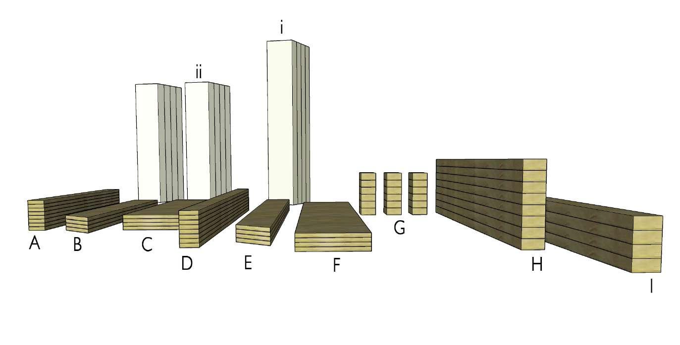
KEY
A 1033 x 2312 x 18mm
B 479 x 2312 x 18mm
C 75 x 2312 x 18mm
D 2361 x 320 x 39.5mm
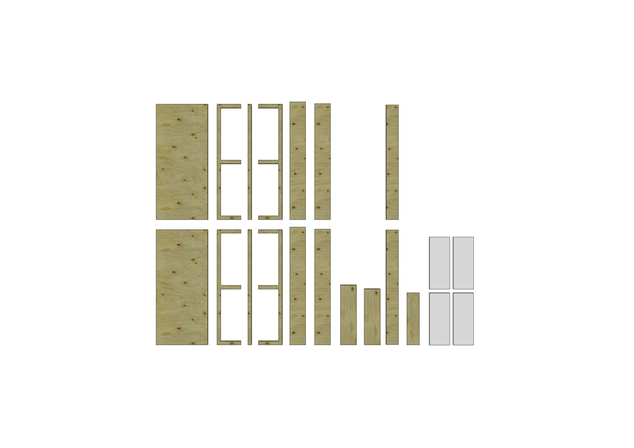
E 2322 x 320 x 39.5mm
F 1200 x 320 x 39.5mm
G 1121 x 320 x 39.5mm
H 2304 x 248 x 18mm
I 1043 x 248 x 18mm
J 1043 x 404 x 30mm
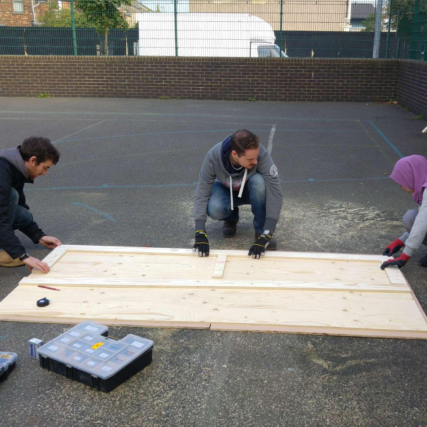
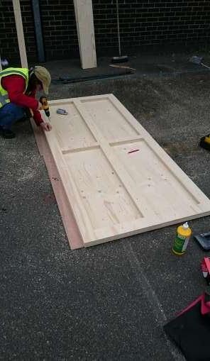
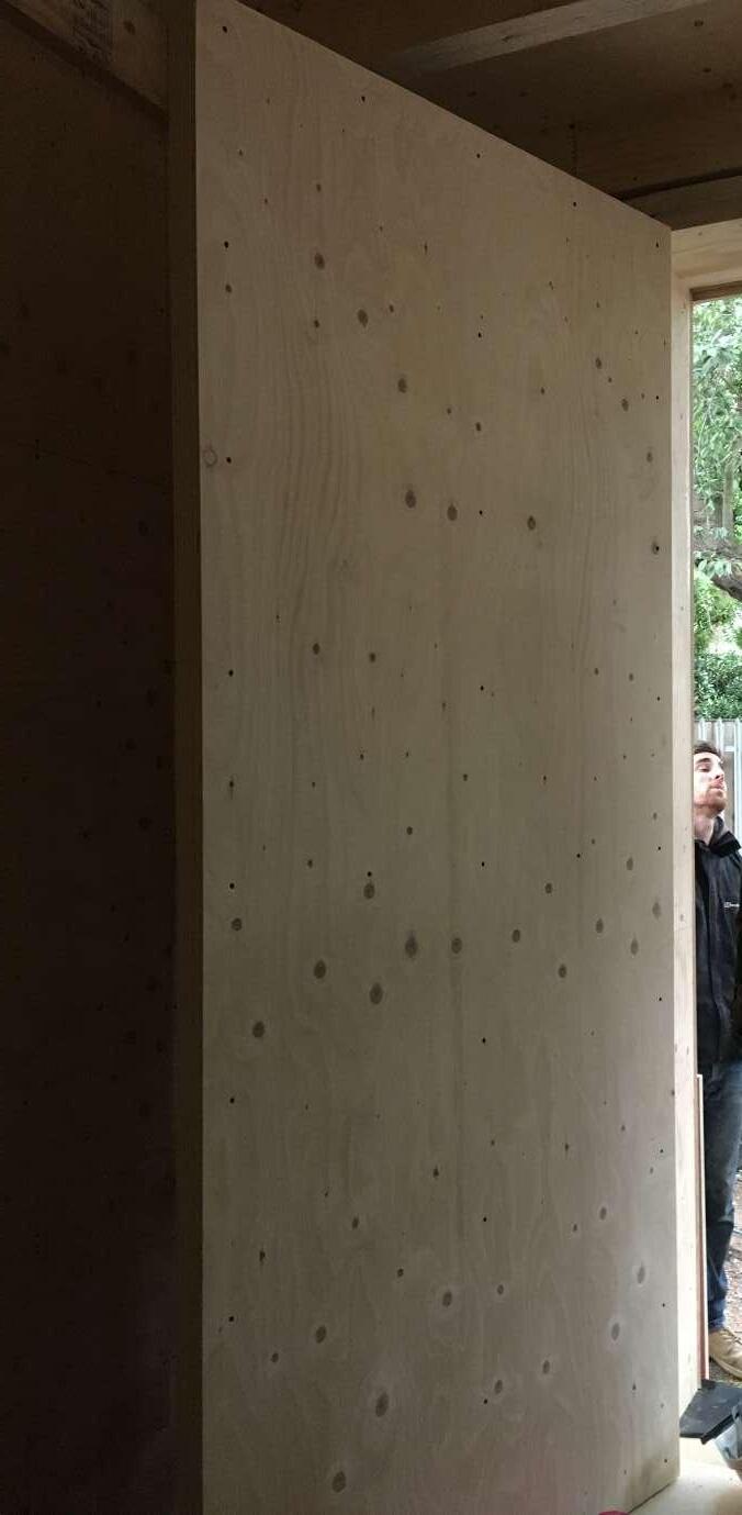
The inner face was positioned on flat ground and the inner frame was laid out. This was then glued and screwed in place. There are two layers of inner frame. These had to be lined up accurately not to overhang.
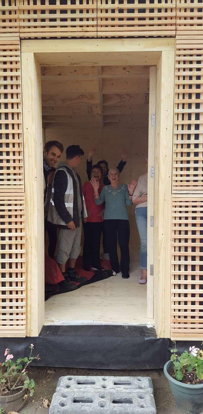
Once the alternating wall boxes were fixed onto place the roof boxes were positioned. The door opening was then complete and is the same height as the internal floor to ceiling level.
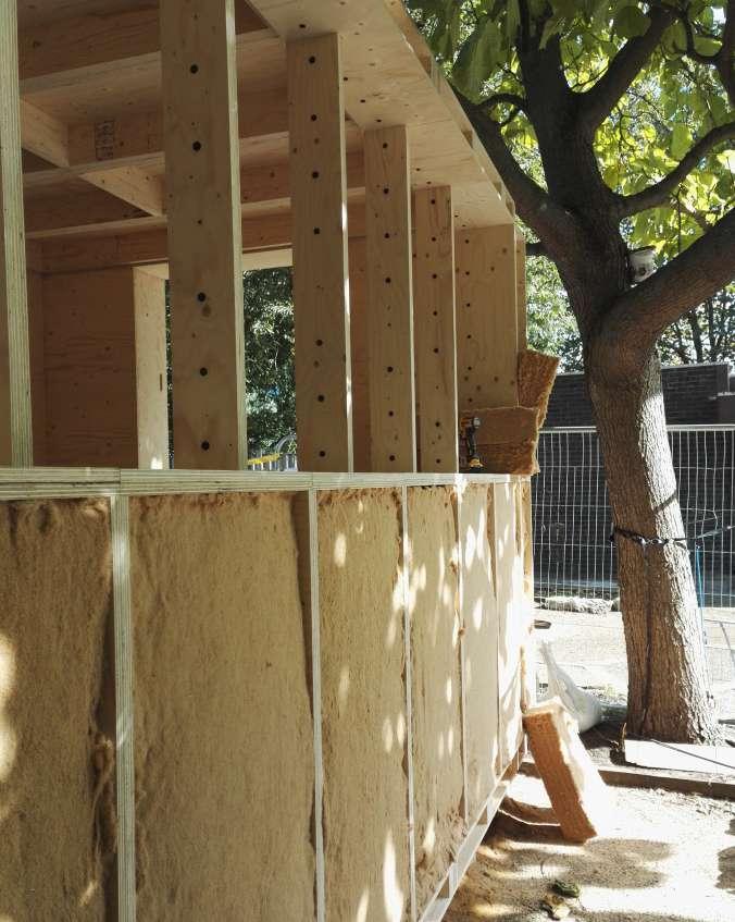
The wall boxes were then filled with insulation and covered in a breather membrane. The breather membrane wraps around the opening and the frame will then fix on top of it.
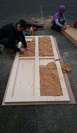
The rectangular trays formed by the inner frame was then stuffed with insulation to minimise the heat loss from such a large opening in the structure.

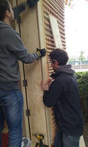
The top outer panel was then positioned and then screwed in. The screw positions had to alternate so that they do not clash with previously made holes. The edgers of the door had to be sanded to minimise any misaligned layers and to provide a smooth finish for the hand.
The frame was screwed into place including the door stop. The positions for the hinges were chisled out and the hinges were screwed in. The door was then hung making sure there is a 5mm tolerance all the way around.
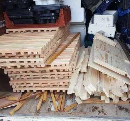
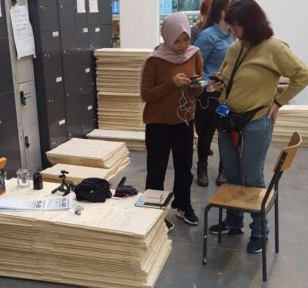
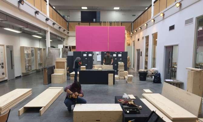
We began with an introduction and project briefing. We received a delivery of all the components to the U-Build, we had to check the delivered parts by measuring and counting all the components in small groups. We then had to compare our finds, there were a few discretions but we managed to correct them all by re-counting and remeasuring. We were taught how to properly assemble and screw together the U-Build boxes.
After a short break everyone sat down together and got assigned their daily task for the 2 weeks we would be working on the project. We also got a quick briefing about the detail and requirements each role. We created a Google drive group including both students and Studio Bark leads to make it easier for documentation and communication.
We spilt up and started to work on our individual tasks. Some of us were writing, putting the camera together, making inventory of plywood parts, taking photos and working on a programme. The new time lapse camera was put together and tested. Our first day went by like most of them do - organising and learning new responsibilities.
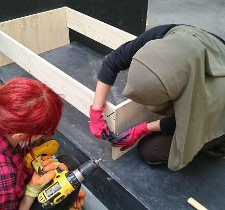
We began with a quick daily brief before we were divided into two groups - The Assemble Team and The Site Team
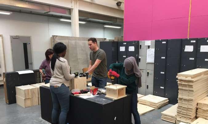
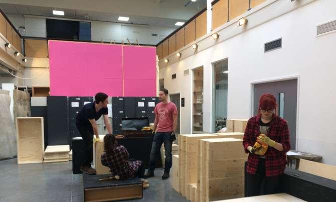
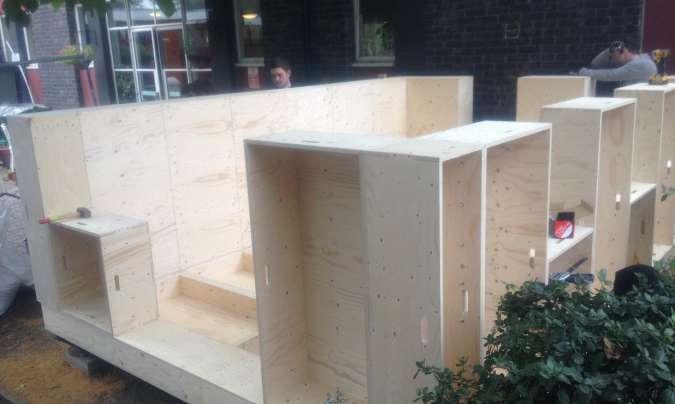
The assemble team started putting together the U-Build boxes for the floor.
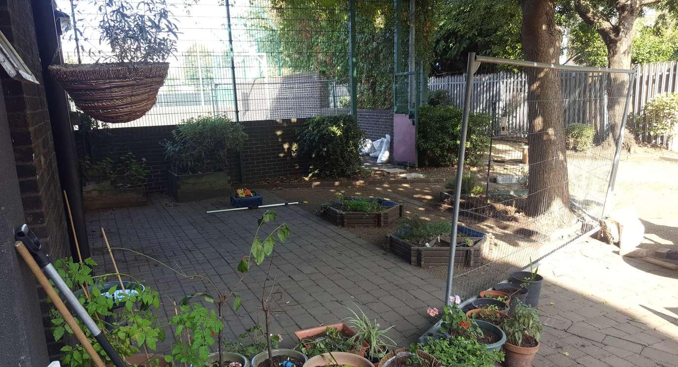
The Site team packed the van with parts and appliances, and drove to the site. The weather turned out to be perfect for outside work. We started by clearing the site and began to transport the sand bags and timber from the van on to the site. Before any other activity could kick off we had a major issue with the site and planning permission. Our site is a courtyard for both the RDLAC and the church next door. While our Lead and the Priest were conversing about the issue The Site Team continued to work and placed the timber on the stakes. The issue was not solved on site and we were asked to hold off on our work until the problem was solved. The Site Team returned back to our working space and helped the Assemble Team.
When the Site Team arrived the Assemble team realised that some initial boxes were built with the faces facing the wrong side. Before the day ended we corrected all and it was checked by the quality control. We ended the day after all the floor boxes were completed.
In the morning we discuss what we have done, what is the plan for today and what we would be doing over the next couple of days. All hands on we continued to assemble the walls, windows and corner U-Build boxes.
Our Lead and two of the members in our team researched and discussed on the process and materials needed to make a prototype for the windows.
The issue of the site was resolved and we received planning permission from the Church. Before the day ended, we packed the flooring boxes, a few of wall boxes and appliances in the van to assemble on site the next day.
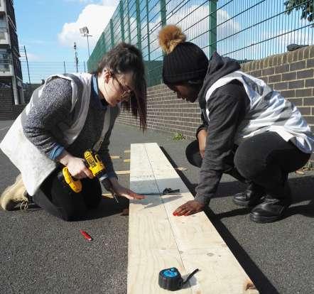
Day four we was back on site, We developed a new routine to assemble remaining floor boxes so that all slide were flush and we kept the minimum tolerance, we split up into teams to assemble the remaining units.
Students continued assembling floor boxes while our Lead
prepared the site by making sure it is level with lasers. Using sand and paving slabs he built up the footings for the base of the building.
Once the base was ready we cut 2 pieces of the breather membrane and stretched them across the square kerto base. There was an overlap in the sheets which were stapled onto the kerto strips. Base was now ready to put the floor boxes on. A small group of us starting preparing the hay insulation and started cutting it down to a variety of size to filled the boxes.
The morning began with an initial programme outline for the work to be undertaken for the day by the team.
Upon completion of the foundations, work was quickly undertaken by a number of team members to complete the floor boxes. The floor boxes were left open on one side to be placed face up so that the cavity can be filled with insulation before the top sheet with the inside face can go on.
An issue arose with screw-fixing the floor finish to the floor boxes with the central location of the noggins and the screw fixings holding them in place leading to the shearing of the screws.
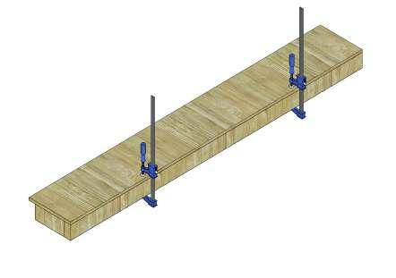
Wall boxes at low level were installed and fixed to the floor boxes using coach-bolt fixings. Once the wall boxes were fixed initially into place. Clamps were used to ensure the required high tolerance between two adjoining wall boxes was achieved. Due to the close proximity with the adjacent property, fixing the wall boxes both to one another and the floor box proved to be difficult for a number of the team members.
The last working day of week ended with the roof boxes being fabricated by two separate teams to ensure the programme was retained for the beginning of the new week..
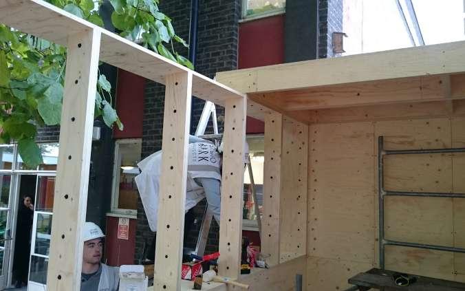
First day of week 2, we started of with our daily meeting and we discuss what the plan is for the rest of the week., followed by us taking out all the elements from the inside of the Garden Room unfinished construction, where they were stored and covered over the weekend for protection. Then we continued with a variety of activities, the team being divided on subgroups working on different tasks as follows. Some people continued to work on the higher level of building, including the frames for incorporating the windows, sub-teams tightened up all the bolts keeping the boxes together. After the walls where tightly joined together and flush. The insulation was double up and we started to install them into the openings. Other team members started to work on the roof elements and
starting going the pieces together.
The group working on the window research multiply ways to incorporate the car boot struts, that was found in a scrap yard over the weekend.
The roof was completed, and all the boxes were now filled with insulation. The whole building was wrapped in damp proof membrane, batons were then attached to one side to secure.
This window concept was developed further with detail sketches and then incorporated into the sketches model of the structure. This concept was further developed until we came to a final decision on how the window would be constructed, including how the window frame would in join the set of car boot hydraulic hinges.
A 1:1 prototype of the corner junction was made to see if our concept was build-able and if it would be sufficient enough to support the glazing. The prototype appeared sturdy but further calculations were required to see if the proposed hinging system, which incorporated car boot hydraulic hinges, would be sufficient enough to support a 1200x 1200 window with 2 pieces of double glazing.
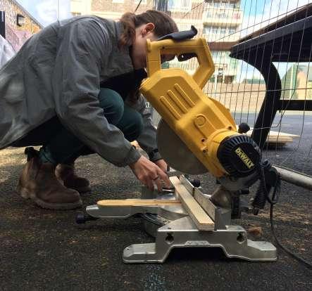
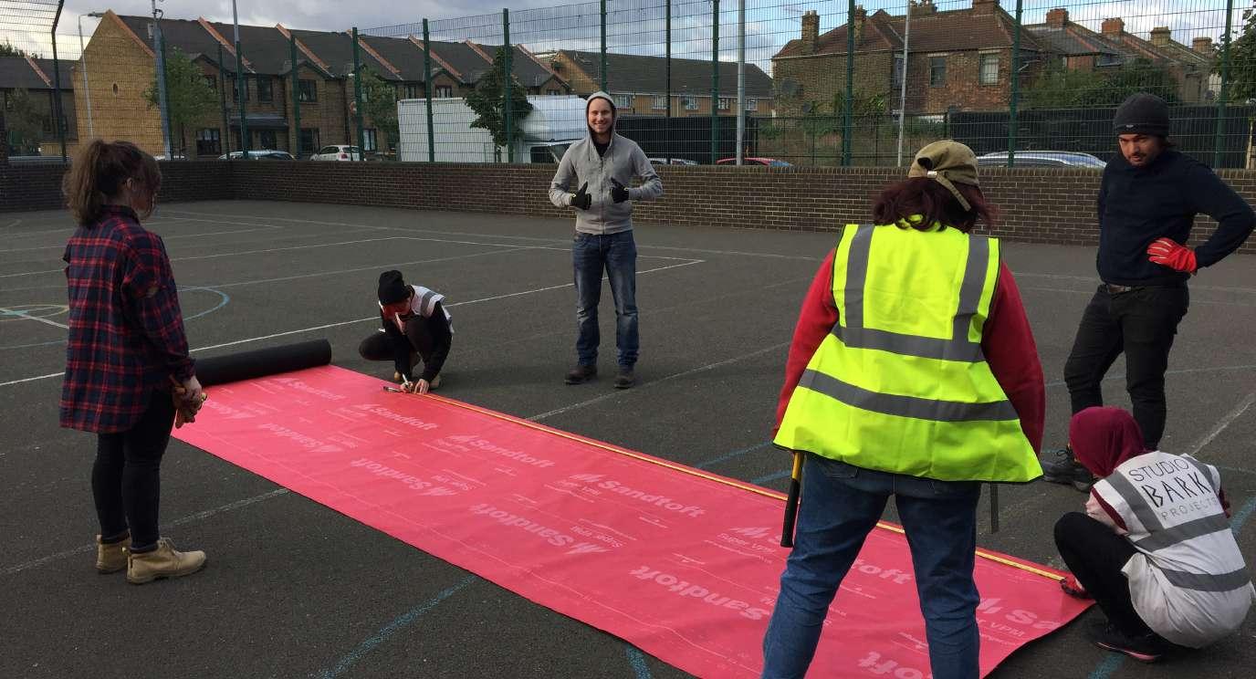
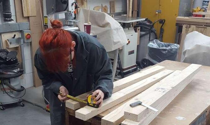
The following day was spent in the workshop cutting the various lengths of timber required for the three windows. While others helped to wrapped the whole building in a damp proof membrane.
The last two day started quite busy. We split into several small teams.
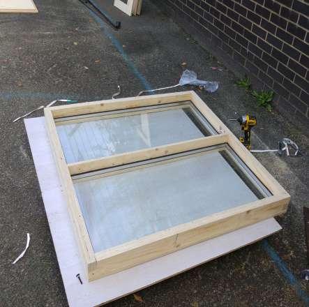
One group was putting together windows, the glazing arrived in the following morning. We had to fit the glazing into the window frame and screw together the remaining pre-drilled pieces. We were relieved to find out that the glazing fit almost perfectly. Another team cut the different components for the door, fitted it and insulated it.
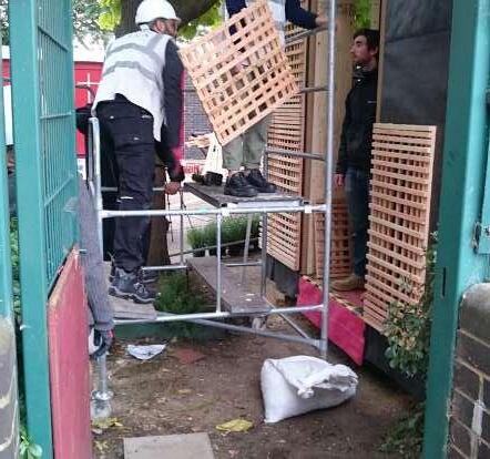
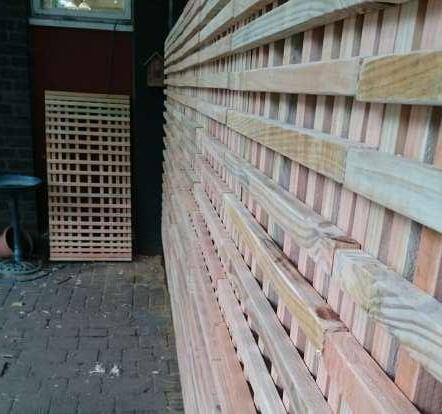
Few members of the cladding workshop joined us on site to fix it to the structure.
One of our team members was working on a way to fix the hinges and pistons to the windows.
Another group started insulating the roof.
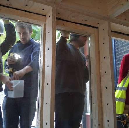
After lunch we continued putting windows together and started fixing window frames into the building. We were anxious if it would fit properly. The last step was fixing windows on hinges to the structure.
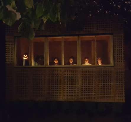
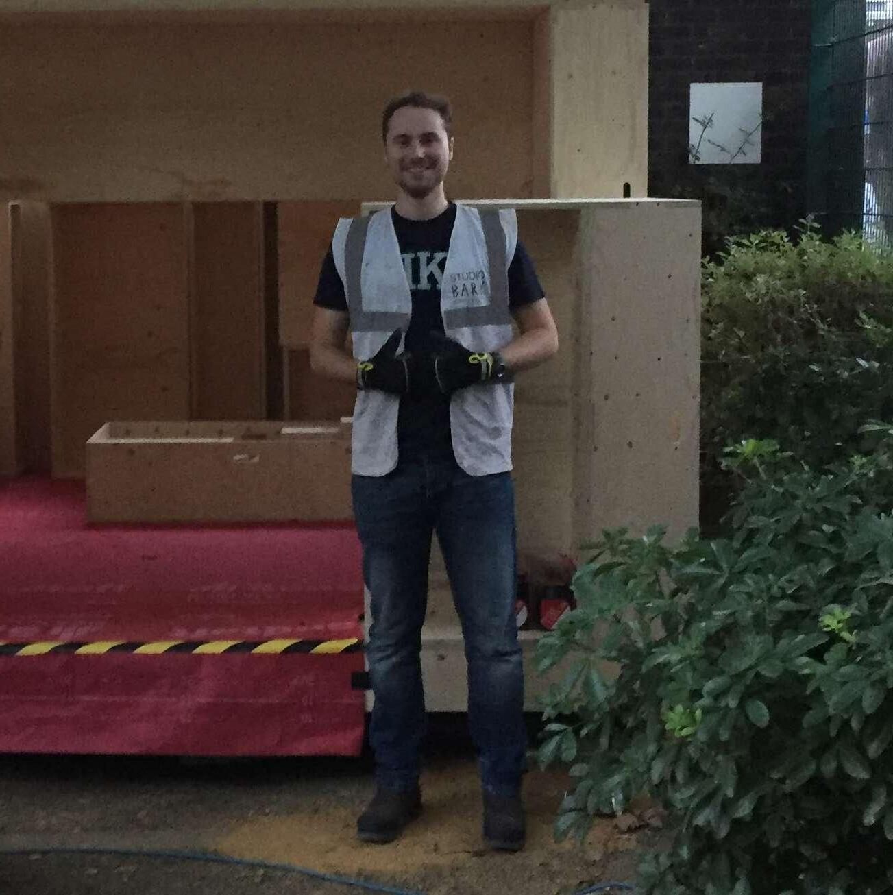
After a long two weeks our job was finally done, we stood proud next to our architecture. As we sat down inside the garden room for a few drinks we took one last group photo.
The U-build structure is exempt from requiring planning permission as it is a temporary building with a planned time of only one year and will have zero energy demand. However there have been complications with the permission granted to Studio Bark to build on the site.
The client shares the site with an adjoining church who owns the courtyard separating the two. The two facilities have historically had a verbal agreement that the community centre can use the courtyard as and when they please. So, when the proposal was brought to the community centre to construct the U-build prototype in the courtyard, they contacted the Bishop of the diocese, who it was believed to be the landowner, and permission was granted for them to build on the site.
But, the church’s facility is shared by two denominations of the Christian church who between them have set up a parish council to make joint decisions on how their site is run. As the parish council were overlooked in the decision making process, the chair of the council (the parish priest) took a stance that the construction could not go ahead without their permission. Unfortunately the next meeting of the parish council isn’t anytime soon and therefore we were forced to down tools until permission was granted. It wasn’t until our first day on site, whilst we were clearing waste that had accumulate over a number of years, that we were confronted with this problem. We were even asked to stop measuring.
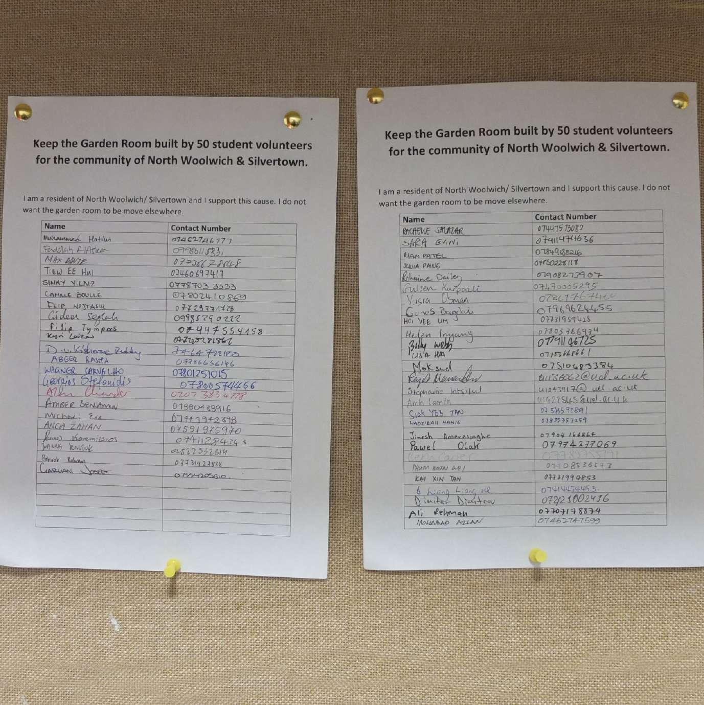
This forced us back to the studio to continue as much of the work there as possible whilst a decision was being made. Seeing as we had a short amount of time to complete the project it was decided by Studio Bark to continue on site whilst the various communications between the community centre and the parish were ongoing, in the hope of being granted permission. On returning to the site we were again confronted by the parish priest and it took the intervention of a local councillor for us to continue. A petition was set up which included the local community, councillors as well as us students to try to convince the parish that what we were constructing would be a great addition to the community and intended for all to use. But, to our dismay, they dug their heels in and as it currently stands the structure is being moved to a new location.
A harsh lesson has been learnt, in future we must be sure to get to the bottom of who has final say in the usage of land and seek agreement from them. It is sad to think what would be an amazing addition to the centre and the parish is being taken away from a community that has for a long time been overlooked. The concept of community spirit discarded by the church of all things. Their grievances are understandable, but to think an amicable agreement couldn’t be reached and to lose an addition to what is now our local community for what appears to be someone craving authority, we are all finding hard to understand
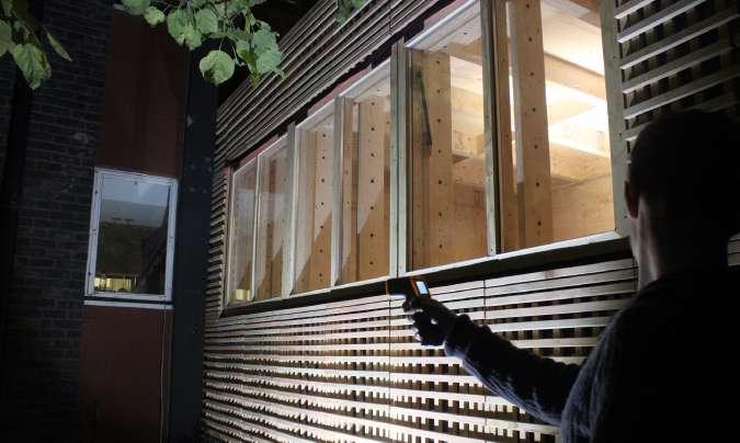
Thermal Imaging
Imaging of junctions wihtin structure
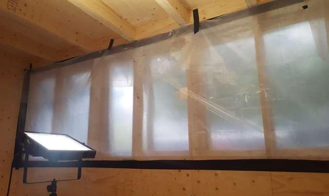
Air Tightness
Windows sealed
Facade Surface Temperature
U-build surface temperature recorded.
Thermal Imaging
Imaging of junctions wihtin structure
Air Tightness
Door sealed and extractor fan used.
Facade Surface Temperature
Existing building surface temperature recorded.
The U-build modular system is aimed at the affordable low-energy self-build market. Consisting of CNC‘d (computer controlled cutting) plywood boxes, the prototype system cleverly interlocks, forming a well-insulated, air-tight and weather-proof building skin. Structural span-boxes for the roof and floor are constructed from LVL (Laminated Veneer Lumber) beams, eradicating the need for expensive and carbon hungry steel. U-build is seen as a flexible and new self-build system, where the simplicity of the fabrication allows people with very little experience in construction to build their own home. And who better than the UEL MArch students to prototype the construction process.
Air tightness is considered fundamental to the energy consumption of a new build, essentially everywhere you have a leak that isn’t for ventilation, is wasting energy. The principle of the U-build system is to build the structure as air tight as possible.
Current building regulations require all new builds to achieve an air leakage of less than 10m3/hm2. That is the air leakage rate per hour per square meter of envelope area, more often referred to as air changes.
There are a variety of problem areas that cause leaks in a building but for this scheme we will be focusing on just the U-build modular system, in particular the junctions where the modules come together through manual construction processes. For this reason we will be hermetically sealing around the door and windows, allowing us to test for where the gaps have occurred during the construction process.
After our 2 week construction process a specialist was employed to conduct the air permeability test was.
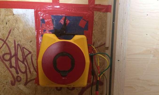
The primary tests were undertaken inside the structure, where we had sealed around the doors and windows whilst a fan mounted in the door extracted air to create a pressure difference between inside and outside of approximately 50 Pa. The air tightness is quantified by measuring the rate of airflow through the fan while a range of pressure differences between the inside and outside of the dwelling are maintained.
Further tests included internal and external building temperature, for both the U-build and the existing community centre. For comparison the community centre had an internal temperature of 22 degrees and an outside temp of 17, whilst the u build structure had an internal temperature of 23 degrees and an external temp of 11 degrees.
This indicates that less heat is being omitted from the u build than the community centre which was to be expected due to the lack of insulation in the makeup of the skin in a building of that age.
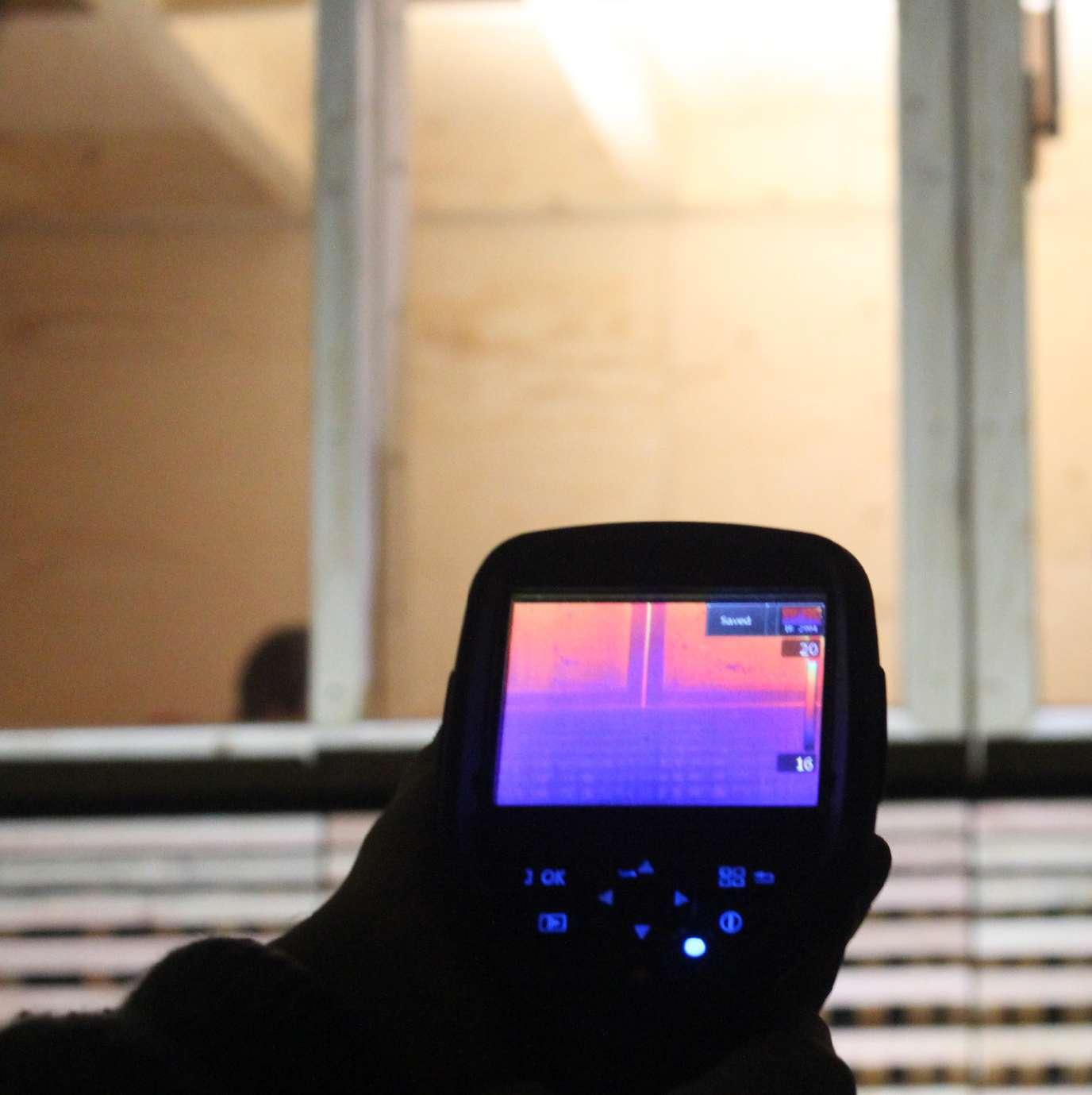
The final test undertaken was with the heat sensor, this device was able to pick up drops in temperature within the structure at certain junctions, which indicated where the construction process hadn’t been as successful. This allowed us to focus on where the the air was leaking and decide how to improve the construction process for that particular area in the future.
„Studio Bark organised the project very well, with students taking on a variety of roles on a daily rota basis, this contributing to the development of new skills. We were given the opportunity to work on all areas, from floor, walls to the roof and cladding. We had inductions and learned how to use different tools like screwdrivers, including the impact ones, and different kinds of saws for cutting on angle and also for insulation, lasers. It was a great experience, with a lot to take on board, in a wonderful team that complemented each other on tasks! The atmosphere was very friendly and everybody was happy to share knowledge! I felt very lucky to have had the chance to work in such a professional manner with everybody!“
Anca„The project was a good start to the year, I saw architecture from another point of view. Being able to see something form up out of nothing was amazing. Working alongside my Uel team and Studio Bark for two weeks gave me a good insight of the U-build concept. The experience expanded my architecture vocabulary and also taught me how to handle hand held machinery. I also learnt how to use your initiative in a more efficient and resourceful way. The first couple of days I had doubts whether we would be able to complete the project by the end of the two weeks. I‘m grateful to have been working with a strong and motivated team.
At the end of the week I was very pleased and excited to be part of this project. It was the first time I‘ve actually built a 1:1 without the help of constructor or builders and it was a success, it shows that there is a future for U-build. “
Mary„The two week self-build challenge was a project that I feel really allowed myself and my fellow team members the exciting opportunity to learn all about this whole new and exciting method of construction, which is one that will hopefully be carried with us through our future journeys in Architecture. By being handson, I feel we were really able to benefit from understanding the innovative technique at a more closer level, and I feel by successfully carrying out this build, we may be able to inspire others to get involved and try it out for themselves. “
Amber„Construction week was a great team-building experience. Working with Studio Bark on their project was incredible, I had the opportunity to design a window and see it being constructed. We learned a lot about working on site and using different tools form screwdrivers to saws. It was a great learning opportunity. We encountered few difficulties, especially with putting the boxes together. The issue with site ownership related to real-work problems that we may encounter during our career as architects. It was a good lesson to keep in mind the assembly process when designing something. After two weeks of hard work it was amazing to enter the Garden Room and sit inside. “
Joanna„I had a really enjoyable two-week project where a group of students became good friends through relentless manual labour. In addition to building relationships we built a garden room with Studio Bark, picked up a few splinters and a few laughs. We learned key qualities involved with building timber structures and how to behave on site. Air tightness, insulation, waterproofing, tolerance, quality control etc. were a few issues that we had to deal with as a team and implement in the construction process. All in all the project came together smoothly and helped to kick start the academic year to come. “
Dionysis
„Specific tasks were divided amongst the members of our team. For the first three days we all worked on making the floor and wall boxes in the atrium of our building at the university, and the rest of the days we were building up the structure of the building on site. For two weeks, we all worked very hard as a team to ensure the project is done on time. After two weeks, we completed the project and the result was very spectacular. I have to say, it was great way to start the semester. We learn to work as a team and got to know each other by working together on this project and it was fun! I personally think that everyone in my team was really great and we had a good teamwork. Above all, working with Studio Bark is definitely a good experience. They taught us a lot about wood construction, the tolerance when making the building to achieve a good air-tightness and how to use tools in correct ways. I‘ve learned a lot and it was a great experience for me and I think it is something that is very useful for future projects and I definitely gained a lot of new knowledge. “
„I feel extremely fortunate to have been a member of the structure team. We were privileged to be part of the development of the U-build concept and to prototype the construction process, which considering our level of expertise in that field (next to none) I feel we equipped ourselves very well. Everyone rolled up their sleeves and gave everything a good go. From day one we were introduced to heavy duty tools which none of us had used before, but with a quick tutorial on how to use them we were off and running. Some of our team are not as physically built than others but that doesn’t mean their effort and contribution, to what is essentially a manual labour, was any less diminished. There were no egos, no slackers and I feel that is reflected in the output we produced. On a personal note, having the chance to make the set of windows with the boot struts to support was a particular highlight, I will never forget the moment when I was holding the weighty 1200mmx1200mm double glazed window and as soon as the struts were fixed in place they began to take the load away from me.
„During the course of the two week project it became apparent that our group of eight, working together on the key fabric of the garden room project alongside the mentoring of Studio Bark proved to be successful from a personal standpoint. Learning this new form of developed self-build system and the skills required to build this system effectively was crucial to its success. During the induction period we were able acknowledge issues that could arise on site and that allowed us as a team to ensure we understand and our current state of construction abilities. As a whole the team work simultaneously with one another ensuring each individual was on task. When issues arose these were dealt with in a professional manner quickly to ensure little disruption to the build programme. I would say that the experience of being able to apply theoretical ideas of construction into a practical situation was an enjoyable experience. “
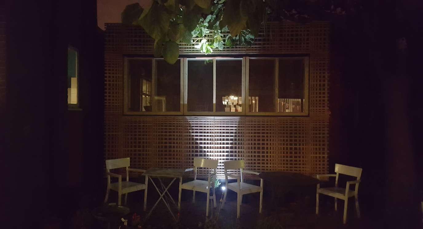
MichaelA wonderful end to the construction came on the final night when we put some candles up and had a few beers in the structure we had all just built. The satisfaction of making and then using a structure, protection from the elements is so fundamental to mankind, it gave a true beauty to our field of architecture. Although unfortunately we now know the structure won’t remain, the memory of the time we spent together and the work we produce will live long in the memory. We had great fun working on this project and I have no doubt we will all remain close.“
GarvanThe Construction Week Group 3A Frame Team was composed from architects from Studio Bark and Year 4 University of East London students.
Nick Newman
Sarah Bland
Steph Chadwick
Wilf Meynell
Within the two weeks the members of the team fulfilled different roles, as established by the Studio Bark architects who were the LEADS, whilst the students fulfilled the other roles on a rota basis system, each student being
LEAD - One of the Studio Bark team will be project leads and are the fist point of contact for:
1) Reporting accidents/injury
2) Confirming the students’ roles
3) Advising on the use of tools
4) Report to for visitors / deliveries
5) Students’ welfare and any problems they may have
CDM - In charge of health and safety. Each day:
1) Check the site cordens and electricla wires are maintained
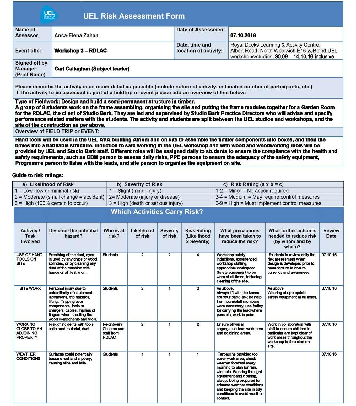
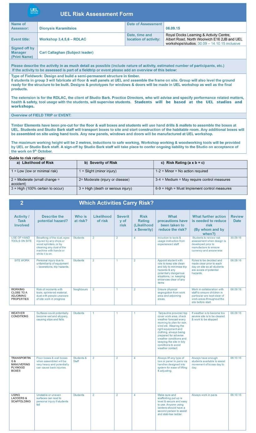
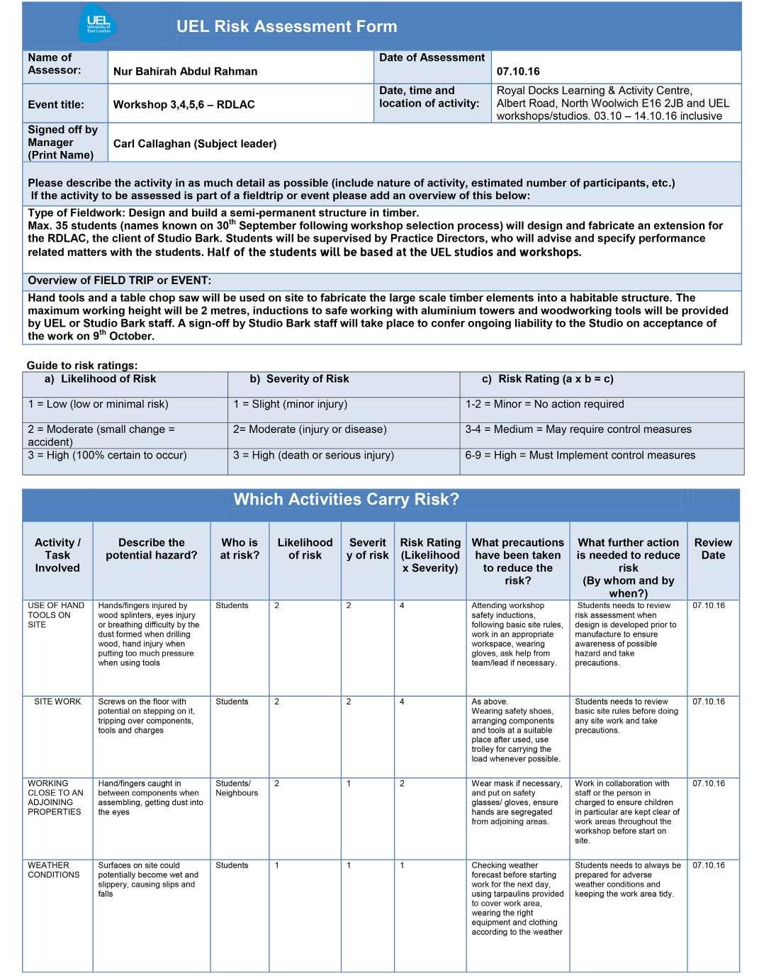
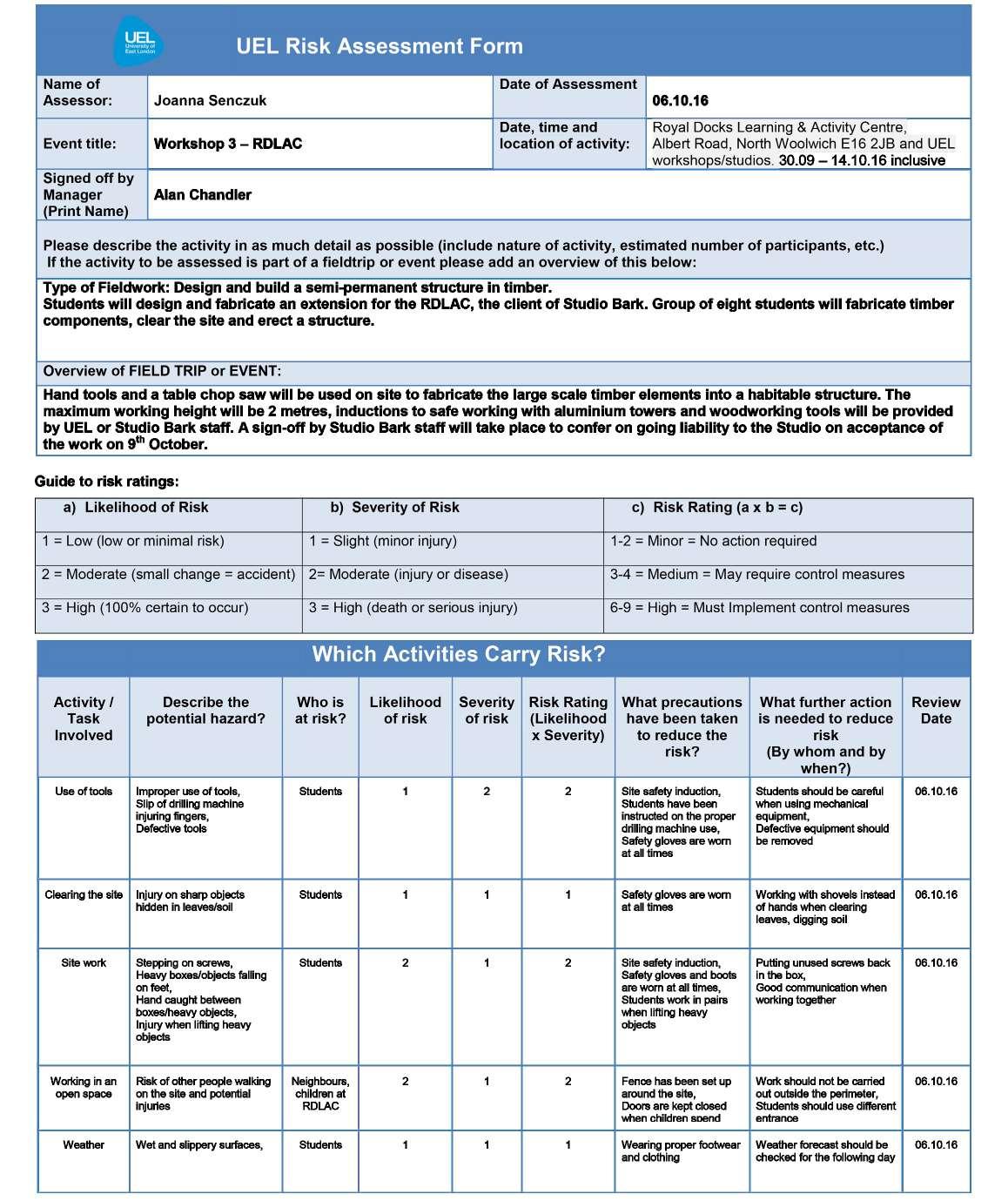
2) Carry out daily risk assessments
3) Carry out PPE and H&S spot checks throughout the day
4) Speak with LEAD as appropriate to check we are conforming with requirements
PROGRAMME
1) Speak with LEAD to agree key targets for the day.
2) Assist LEAD to programme out key tasks for the build proper.
3) Liaise with LEAD and FOOD regards food and tea break
4) Keep everyone aware of the time and how long they have left to do certain tasks
5) Ensure everyone is aware of their daily tasks
Amber Benjamin
Anca-Elena Zahan
Dionysis Karamitsios
Garvan Joseet
Joanna Senczuk
Mary Folorunso
Michael Eve
Nur Bahirah Rahman
SITE
1) Organise site equipment throughout the day. Check to see if people have finished with tools and put them back
2) Check through deliveries against the delivery note
3) Keep receipts record
4) Maintain stock/ to order list.
FOOD - Organise tea breaks, organise lunch and clear up
1) Look for waste on site throughout the day
2) Separate waste metal, wood, plastic, recyclables into boxes
TWEET / PHOTO
1) Speak with PROGRAMME and LEAD to agree key eventsto document
2) Use site camera throughout the day
3) Download photographs
4) Liaise with LEAD regarding tweeting
5) Help with stop motion
1) Take notes of key moments in day
2) Liase with TWEET to get the best and most relevant photos
3) Write up blog on Google Drive and review with LEAD
BUILD - Filling in for missing persons, helping out other roles or doing extra tasks not covered by the other roles