U-BUILD FRAME 2016
RDLAC Community Centre, Albert Road, London, E16 2JB
CONSTRUCTION WEEK 2016
UNIVERSITY OF EAST LONDON
Amber Benjamin
Anca Zahan
Dionysis Karamitsios
Garvan Joseet
Joanna Senczuk
Mary Folorunso
Michael Eve
Nur Bahirah Abdul Rahman
Report Submission Date: 18/11/2016
1
2 U-BUILD FRAME 2016
This book has been written as both a diary and instruction manual of our experiences and developed knowledge during the construction of the U-build 2016 garden room and the Royal Docks Learning & Activity Centre in North Woolwich. The frame team have aimed to produce a document that describes key details of the process of erecting this new type of construction using CNC cut birch components developed by Studio Bark.
Studio Bark a local architectural practice based in East London have developed a system of birch CNC cut components that allow the “self builder” to erect their homes minimising the cost of contractors and externally hired professionals that today increase the average budget of a traditional new build home.
Our experience of working and erecting this new pre-fabrication system has been clearly documented within this book, describing our daily tasks and overcoming of site related issues through a diary within this book.
3
[ PREFACE ]
[
ACKNOWLEDGEMENTS ]
We would like to take this opportunity to acknowledge the individuals and insititutions that made it possible for group three to undertake U-build during construction week 2016.
[ STUDIO
BARK ]
Wilf Meynell
Nick Newman
Sarah Bland
Stephane Chadwick
[ RDLAC COMMUNITY CENTRE]
[
4 U-BUILD FRAME 2016
UNIVERSITY OF EAST LONDON ARCHITECTURE DEPARTMENT ]
5 [ CONTENTS ] PROJECT INTRODUCTION 1.0 SITE CHARACTERISTICS 2.0 PRECEDENTS 3.0 U-BUILD PROPOSAL 4.0 U-BUILD BOXES 5.0 PARAPET DETAIL STUDY 6.0 WINDOW DETAIL STUDY 7.0 DOOR DETAIL STUDY 8.0 CONSTRUCTION WEEK DIARY 9.0 LOCAL OPPOSITION 10.0 AIR TEST 11.0 TEAM REFLECTIONS 12.0 APPENDICES 13.0
6 U-BUILD FRAME 2016
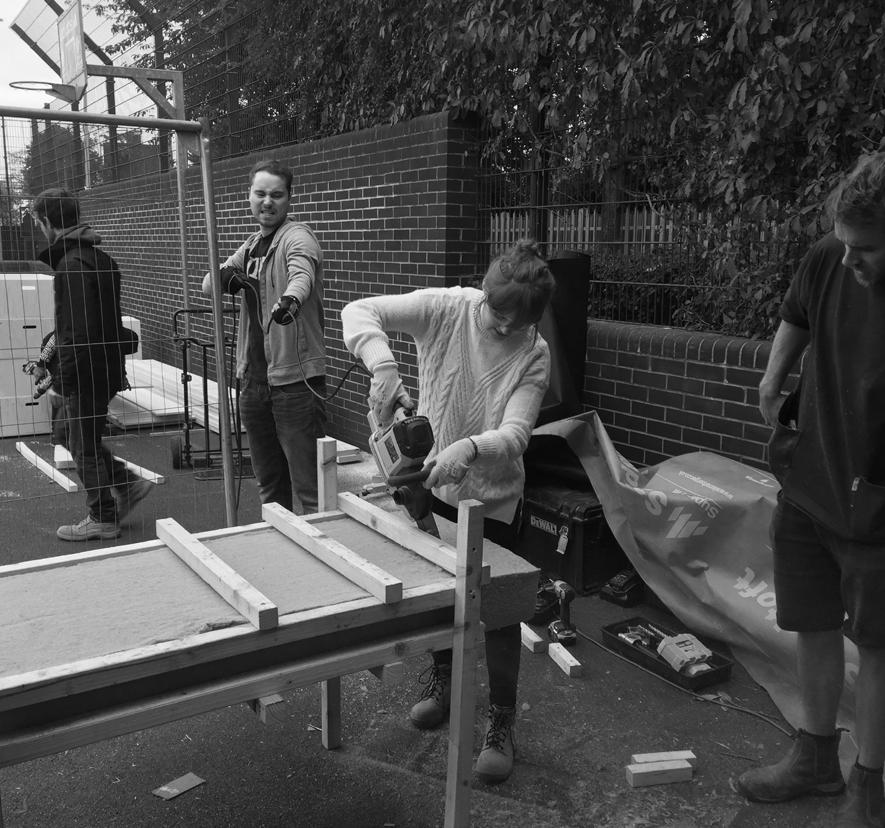
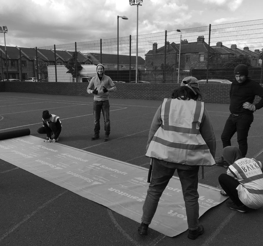
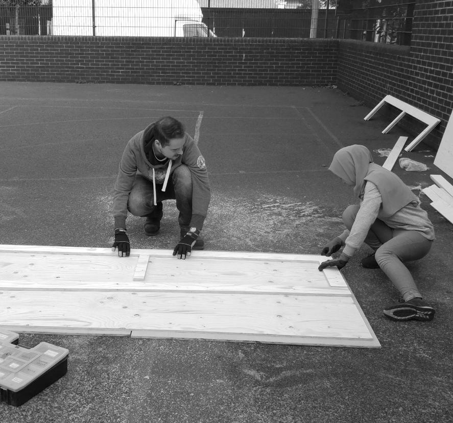
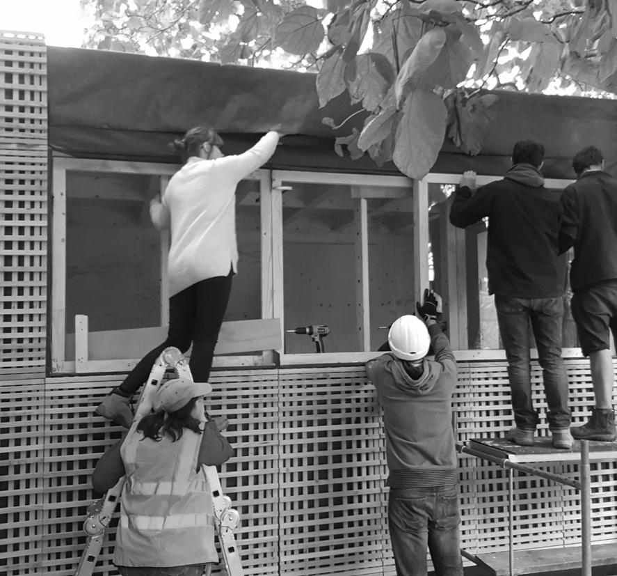
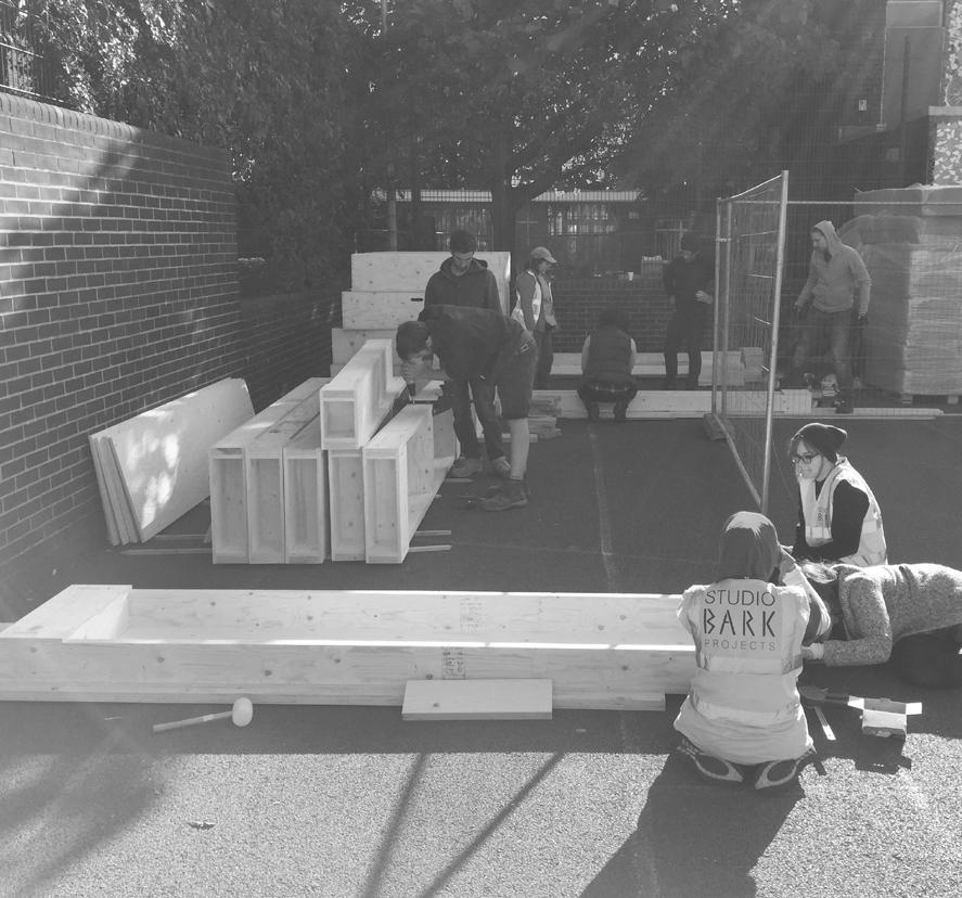
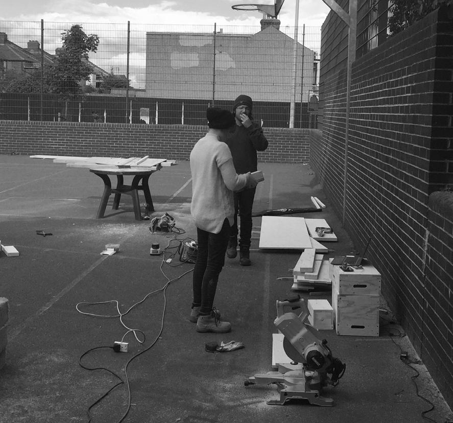
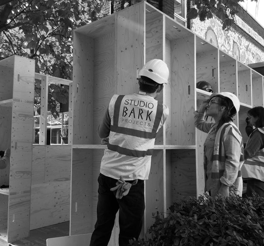
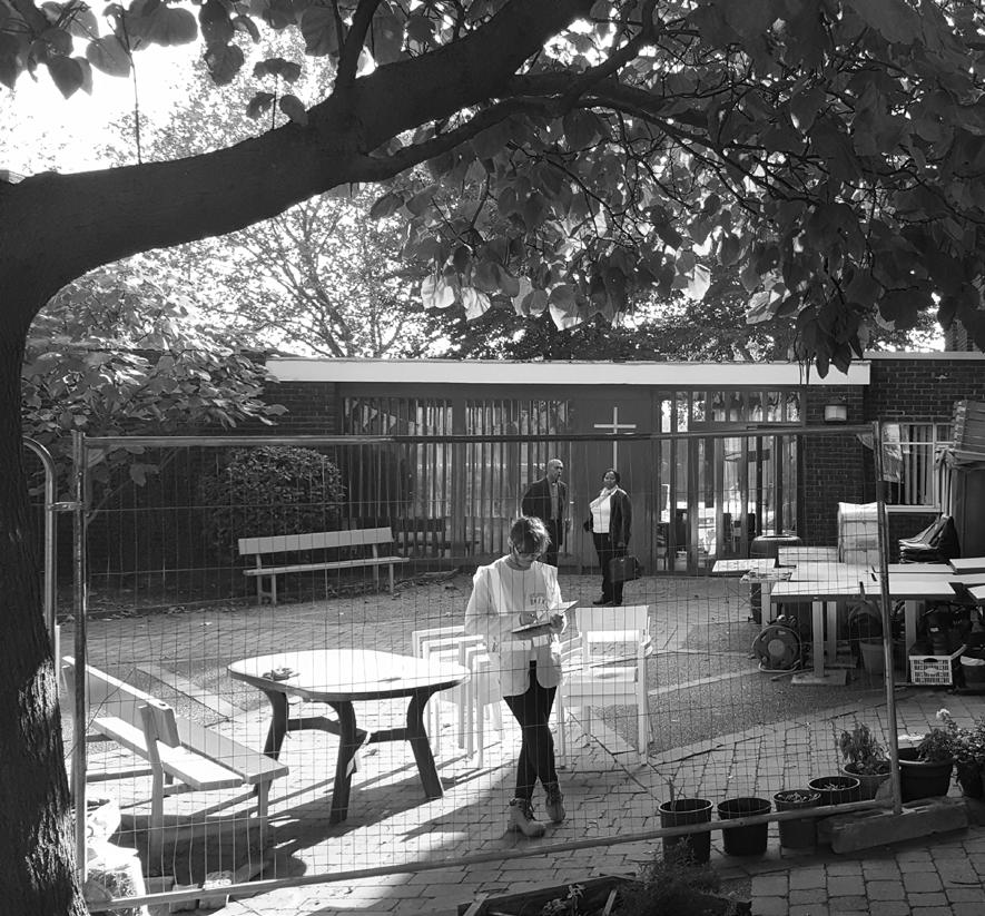
Fig.01 - Photo from construction week
Fig.02 - Photo from construction week
Fig.03 - Photo from construction week
Fig.04 - Photo from construction week
Fig.05 - Photo from construction week
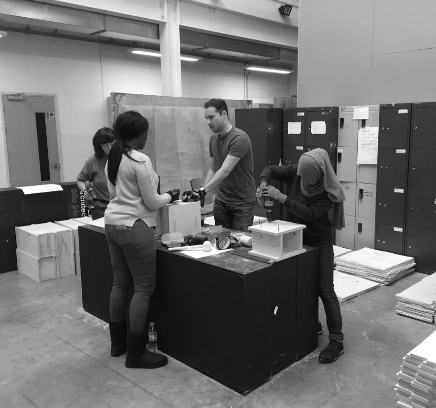
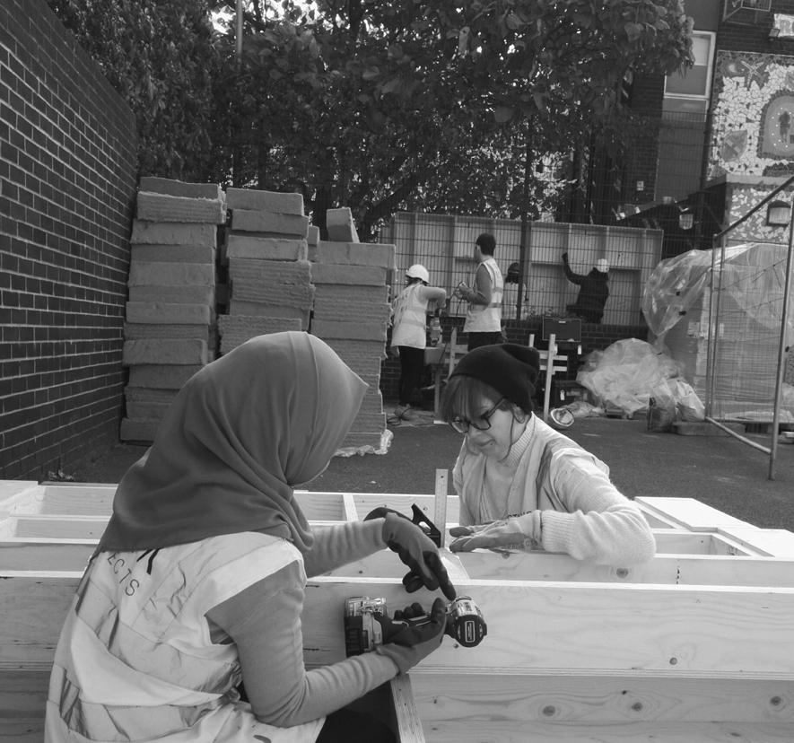
Fig.06
- Photo from construction week
Fig.07 - Photo from construction week
Fig.08 - Photo from construction week
Fig.09 - Photo from construction week
PROJECT INTRODUCTION 1.0
The project aim was to build a new form of construction prototype developed by Studio Bark. The site location was Royal Docks Learning and Activity Centre in North Woolwich within a shared courtyard with St Johns Church. This sharing of the land and the construciton of the garden room and the issues faced will become more apparent during the course of this report.
Our task as a small team of eight students was to aid in the erection of the frame and aid the studio in overcoming any issues that may become apparent during the build. We would also be tasked with manufacturing two of the key components to securing and weather proofing a building and this will be explained in more detail.
The overall aim of the project was to ensure what we had constructed as a novices in construction could be built effectivley to remove the industries dependance on the contractors once again allowing the self builder an opportunity to havve control of their build.
Once completed the garden room will be tested by an industry professional for its energy efficiency and whether this type of the CNC components construction is feasible in an age of high environmental aspirations for any building.
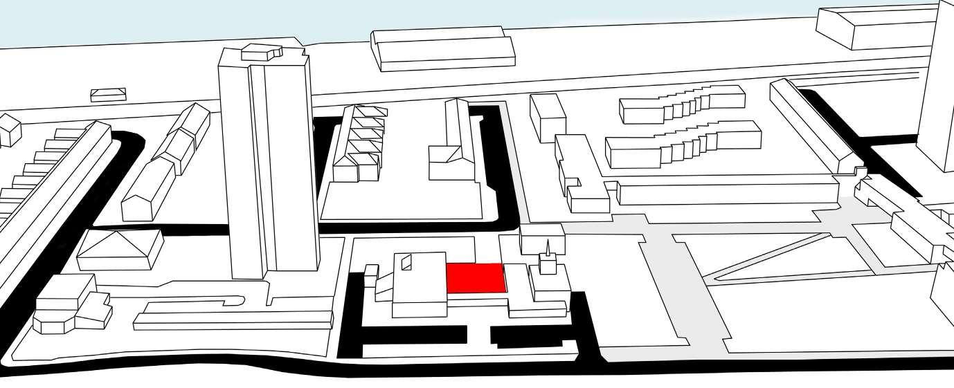
07
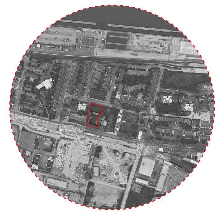
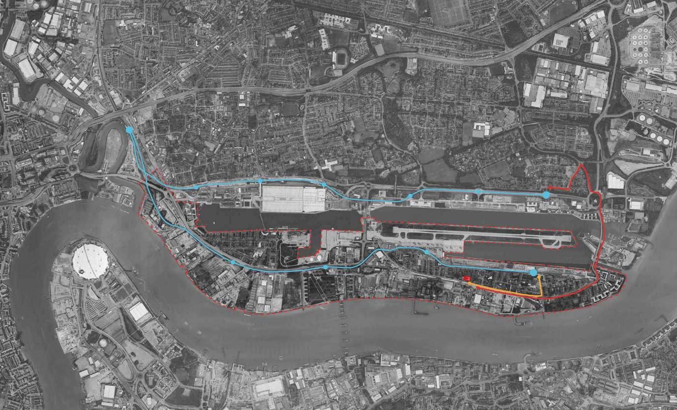
- Area drawing of the site.
Fig.10
SITE LOCATION PLAN
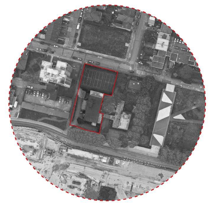
08 U-BUILD FRAME 2016
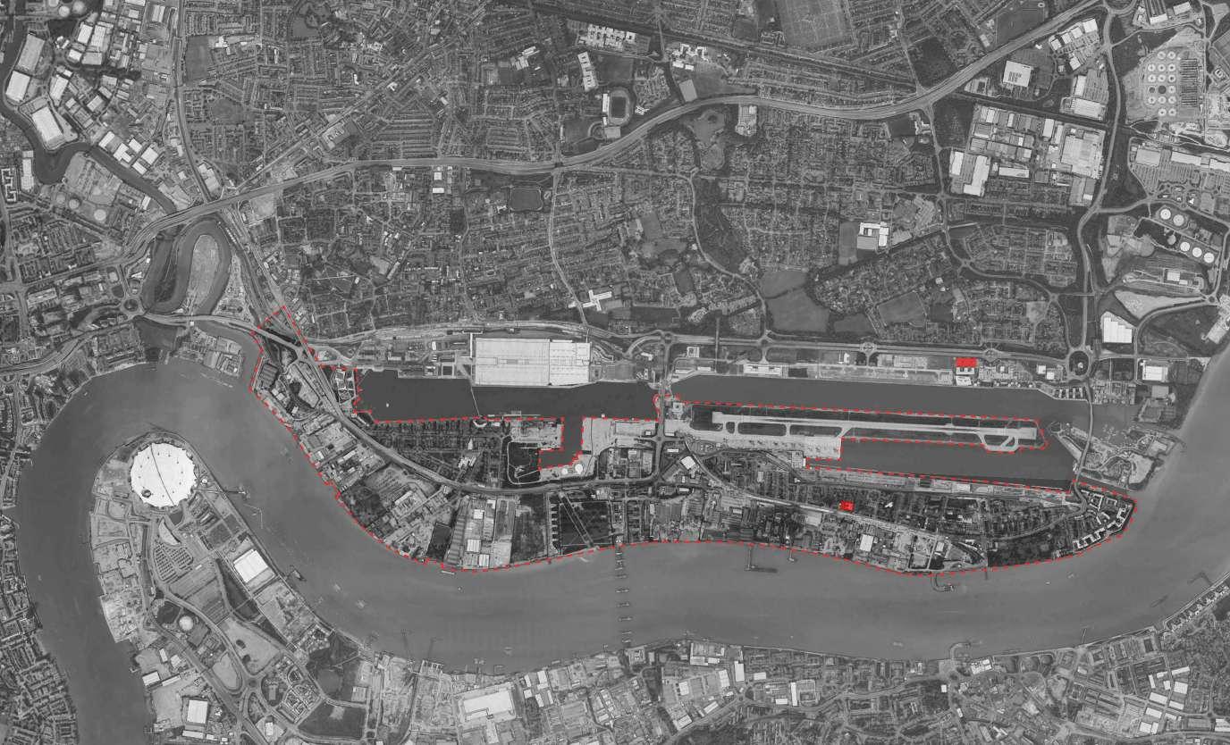
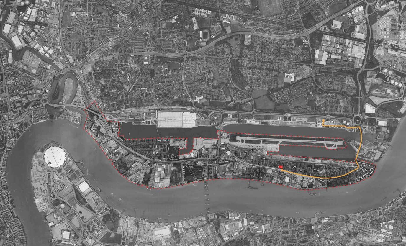
Fig.11 - Satellite Location Plan
Fig.12 - Satellite Location Plan

09
Fig.13 - Site Proximity Plan
SITE PROXIMITY TO UEL DOCKLANDS CAMPUS
[ WALKING FROM UEL ]
TOTAL WALK TIME [ 19 MINS ]
EXIT TO THE EAST OF DOCLANDS CAMPUS
WALK ACROSS SIR STEVE REDGRAVE BRIDGE
TURN RIGHT ONTO ALBERT ROAD
FOLLOW ALBERT ROAD WEST TO CENTRE
SITE PROXIMITY TO UEL DOCKLANDS CAMPUS
10 U-BUILD FRAME 2016
Fig.14 - Walking Plan
[ LONDON UNDEGROUND SERVICES ]
CYPRUS TO CANNING TOWN [ 10 MINS ]
CANNING TOWN TO KING GEORGE [ 15 MINS ] VIA CITY AIRPORT
WALK TO CENTRE [ 5 MINS ]
[ LONDON BUS SERVICES ]
BUS 457 FROM CYPRUS PLACE [ 10 MINS ]
TOTAL OF NINE STOPS
TO DEPART BUS AT PIER ROAD STOP
WALK TO CENTRE [ 2 MINS ]
SITE PROXIMITY TO UEL DOCKLANDS CAMPUS
Fig.15 - Transport Plan
11
12 U-BUILD FRAME 2016
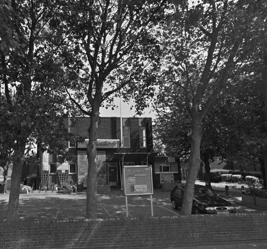
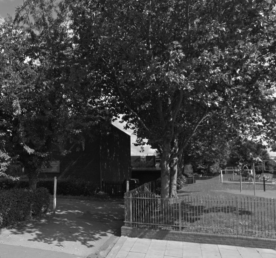
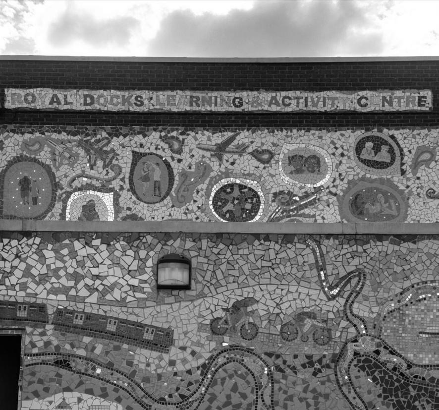
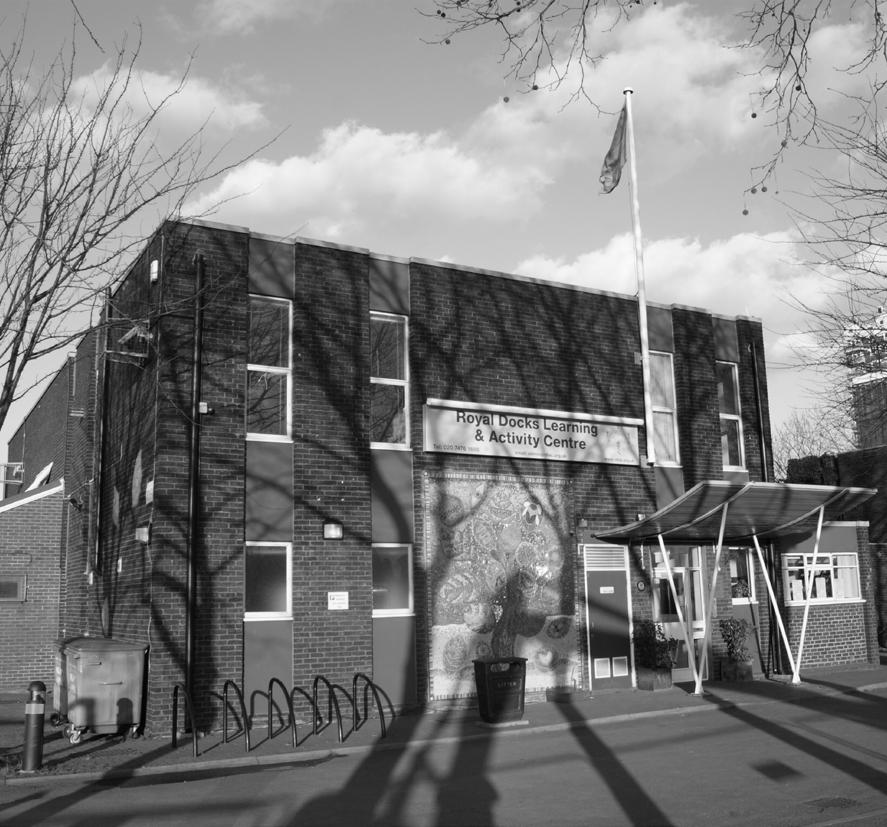
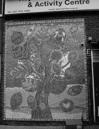
Fig.16 - Context image
Fig.17 - Context image
Fig.18 - Context image
Fig.19 - Context image
Fig.20 - Context image
Fig.21 - Context image
Fig.22 - Context image
Fig.23 - Context image
Fig.24 - Context image
RDLAC COMMUNITY CENTRE
The Royal Docks Learning and Activity Centre is located in North Woolwich and has been an intricate part of the social fabric of this particular area of London since its opening in 1968. The centre has offered local children, familes and the elder generations an opportunity to socialise, learn new skills with the varied classes and sessions available to all.
The centre historically only supported local children in its infancy as a community centre in 1968. It wouldnt be until the 1970‘s that the community would branch to include the older generation in newly formed programmes and activities.
The centre historically was a registered charity until 2001 where key stakeholders agreed on the centre becoming a registered company with Company House. Since this period the centre has seen vast changes both within its company set up, changes of chairmans and the wider adoption of new programmes supporting a vastly declining area of east London.
WIDER CONTEXT:
While the centre has remained an integral part of the community and has remained at its original location the wider area of North Woolwich has changed vastly since 1968 and the centre has had to adapt to cater for needs that have become apparent.
North Woolwich historically was part of the major Docks of the east end, with major imports and exports within the local vercinity of the island. The island itself was a key railway depot and supported the import and export trade. The Tate and Lyle sugar factory which has stood on the southern river bank of the island is still in production today.
Since the closure of the docks, the island has been drawn into a major state of disrepair. While the sugar factory is still in production and one of the major employers on the island, there is high unemployment and many buildings are seen to be below typical standards.
Much of the island‘s decline as noted by a number of local residents was the construction of the DLR railway which connects the island to the city and further onto Woolwich south of the Thames. Many have seen this connection through the DLR as the point in which local trade on the island decline greatly.
Currently Crossrail has compulsory purchased the majority of the existing land in front of the community centre to continue with the major project.
1968: Formation of the community centre. St Johns Church Community Centre.
1968: Implementation of programmes to provide youth schemes.
1970’s: Programme undertaken to incorporate local activities for the wider community.
2010: Stakeholders put forward plans to rename the community centre.
2001: Charity becomes a registered company with Company House.
2014: Application submitted for funding to undertake programmes for the over 75’s in the local area.
2010-2011: Name of centre is changed too; Royal Docks Learning & Activity Centre.
13
2000’s 1960’s 1970’s 1980’s 1990’s
1.1
14 U-BUILD FRAME 2016
- Site Location
Fig.25
Plan
SITE LOCATION PLAN SCALE: 1:500 @ A4
SITE CHARACTERISTICS 2.0
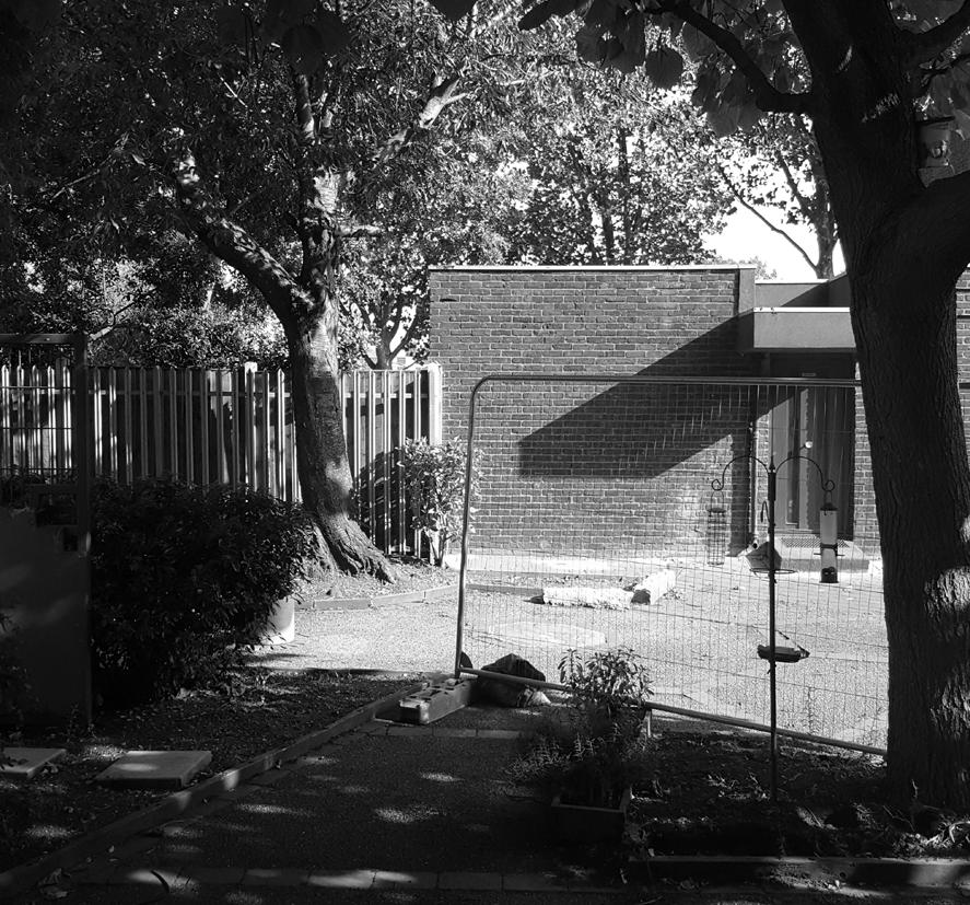
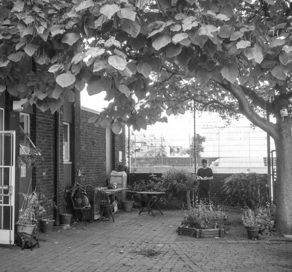
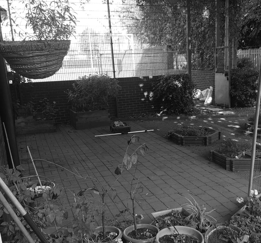
The site is located at the local Royal Docks Learning and Activity Centre on Albert Road in East London. The RDLAC community centre was established in 1968 and has served the local community through various public activities and local events. The site for U-Build is situated within the grounds of the site between the community centre and the local church parish.
The site has a number of existing characteristics within the proximity of the U-build site and consideration of final building location and heights have been considered during the various stages of planning the commission for the community centre.
The site is fairly flat with a minimal 90mm runoff towards the east of the site. One of the key constraints of the site is the existing Bean Tree that is located directly on the eastern flank of the U-Build garden room.
The canopy of the tree is fairly minimal compared to various trees within the wider proxmity of the site but has limited the height of the garden room on its padstone foundations.
While the remainder of the site is flanked by the existing community centre and boundary wall to the playground on the northern extent of our site. Below are a set of the constraint and parameter diagrams that describe the existing issues with the chosen location for the U-Build Garden Room.

CONSTRAINTS LEGEND.
SITE ACCESS POINTS
NOISE ISSUES
RESTRICTED ACCESS POINTS (9-6pm)
CHANGE IN GROUND LEVEL (FALL TOWARDS SITE BOUNDARY)
EXISTING VEGETATION CONSTRAINT
CLIENTS BUILDING BOUNDARY
ST JOHNS CHURCH OWNERSHIP BOUNDARY
SHARED LAND RIGHTS THROUGH DEEDS
15
Fig 26 - Constraints Plan
Fig 27 - Constraints Legend
16 U-BUILD FRAME 2016 Fig.28 - Levels Survey LEVELS SURVEY OF THE SITE [ KEY ] - BUILD SITE - WIDER AREA + +
PARAMETERS
Although as a project our involvment was for the build stage only (RIBA Plan of Works Stage Five - construction), during the project we have been able to identify a number of key site parameters that confirmed the current location of the garden room as the ideal location with the courtyard.
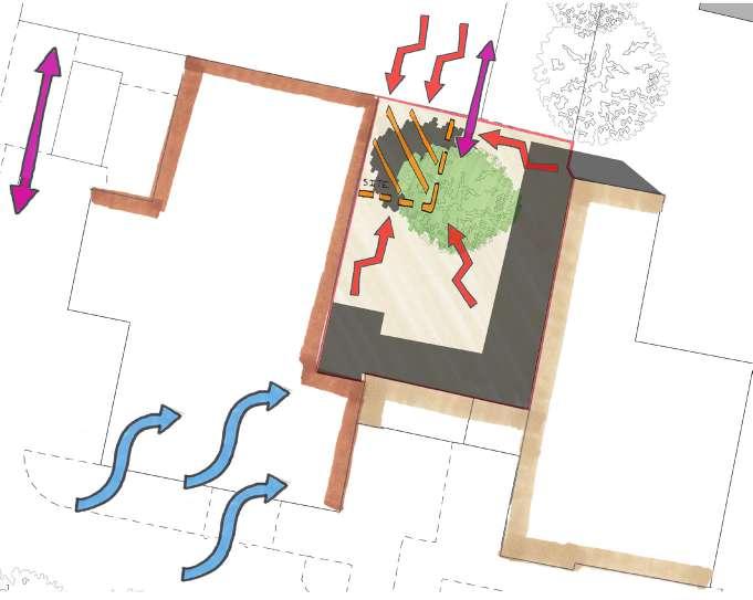
The garden room has been located within an area of the courtyard that offers numerous benefits in terms of; protection from prevailing winds, direct sunlight and the stability of the ground topography.
One of the key issues when construction began was the level of the foundation padstones, due to its proximity to the adjacent community centre and the recently rebuilt groundworks by a local contractor, the ground was fairly level for the build with a maximum level change of 90mm as shown on the levels drawing opposite.
Other benefits of the site location is the bean tree and its large overbearing canopy to the north west. To ensure that the garden room‘s internal temperature can be regulated and protection from the natural heating of the sun. The tree‘s canopy will ensure that there is a reduction in the level of natural light being ommitted onto the external surface of the building.
Typically stong south westerly winds found in this particular area of the country have also been reduced due to the two storey height of the community centre as shown in the parameters diagram below.
Fig 29 - Parameters Plan
PARAMETERS LEGEND.
SITE ACCESS POINTS

PREVAILING WINDS (SOUTH WESTERLY)

OPTIMUM GROUND LEVEL LOCATION (Towards 0.0)
OPTIMUM GROUND LEVEL LOCATION
EXISTING CONTEXT SHADOWS (11AM)
CLIENTS BUILDING BOUNDARY
ST JOHNS CHURCH OWNERSHIP BOUNDARY
SHARED LAND RIGHTS THROUGH DEEDS
17
2.1
Fig 30 - Parameters Legend
18 U-BUILD FRAME 2016
Fig.31 - Example of system process
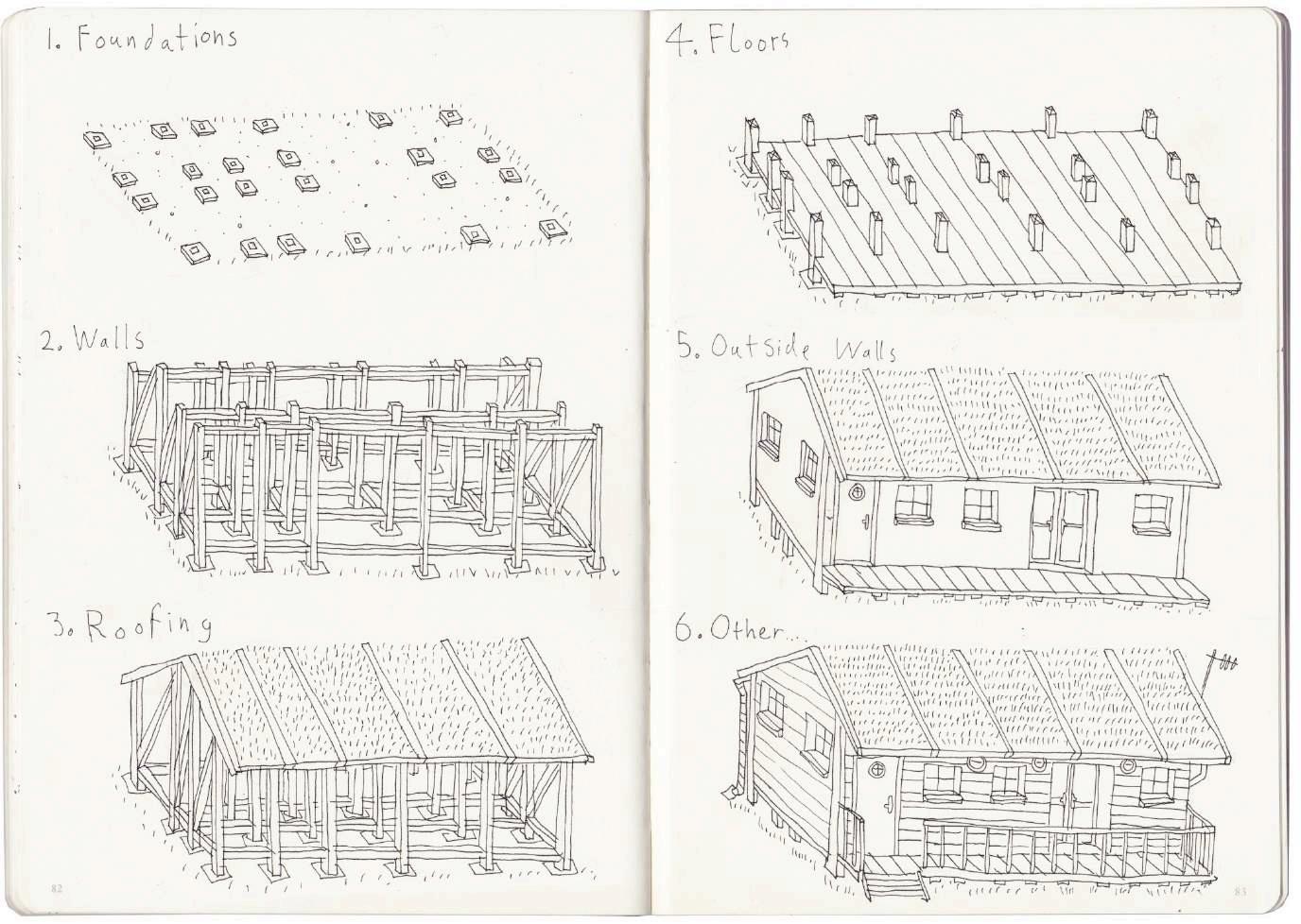
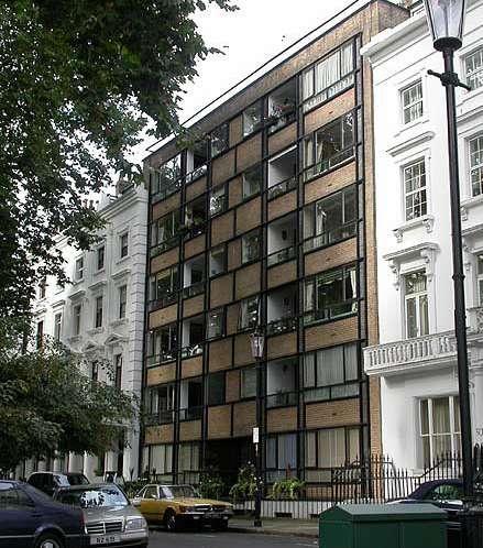
PRECEDENT - WALTER SEGAL 3.1
Walter Segal, born 1907 in Berlin Germany was an Architects who’s work within the self build sector of architecture had developed a key process of constructing self build homes for the masses. His self build system dubbed “Segal Self Build Method” was entirely dependant on using a traditional timber frame which had been modified to use standard modern material components.
Segal’s method of construction has eliminated the need for wet trades which today are still wider used almost 50 years on from his proposal, in which these typical wet trades of bricklayers, plasterers and concrete pourers are still widely used. His method of construction has a key structural advantage in being a lightweight system which can be built with minimal experience in construction, making it widely available to average individual.
His approach was to express the details and understanding of the medieval English home and American frame house system. Unlike these systems the Segal system calculated the timber frame based on the modular dimensions to avoid waste and include opportunities for alterations and enlargements to the home.
19
Fig.33 - Knightsbridge, London
Fig.32 - Example of the system

20 U-BUILD FRAME 2016
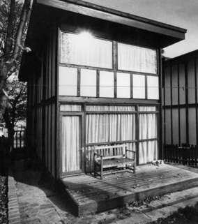
Fig.34 - PopUp House 1
3.2
PRECEDENT - PopUp HOUSE
The PopUp House, also known as the Lego house, has been developed in France and consists of 5 major steps.
1. Pre-project
Once the client has got the money and land, the company will put them in contact with a local architect, home builder or constructor, who will become the main contact.
2. Conception
Duration: 4-8 weeks. Once the client and the architect agree on the design and get the construction permit, the company deals with the technical aspects.
3. Sitework
Duration: 6 weeks. PopUp house accredited companies will construct the house, although the house is mainly advertised as
a self-build.
4. Installation
Duration: 1-2 weeks. The foundation is layed down and the PopUp House is assembled.
5. Fitout
Duration : 1-3 months. The frame is personalized with the preferred finishes and services. This can be done by the owner or a professional.
The house is simple to build and is affordable, due to the inexpensive materials and quick assembly, also due to its low energy consumption thanks to exceptional insulation.
PopUp House is not a homebuilder, the building system is sold to the professional who will build the house.
21
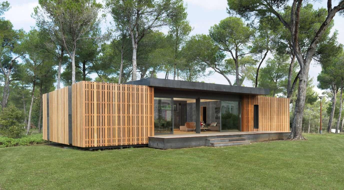
Fig.35 - PopUp House 2
22 U-BUILD FRAME 2016
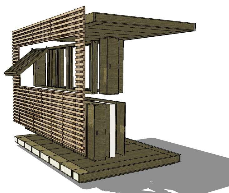
Fig.36 - Exploded Visual
U-BUILD PROPOSAL 4.0
There were three main projects that would come together to complete the overall build. These projects were the following: Project Frame, Project Cladding, and Project Roof.
Our particular project concentrated on the Frame of the building. This meant looking at the design of an exciting and unique construction method, which could utilize a single and adaptable kit-of-parts system.
This innovative and low impact U-Build system was designed not only to be flexible, but also enhance the speed of constructionall without severely limiting the buildings ability to merge into an urban fabric.
Each piece of timber was pre-cut and routed specifically, in order to be able to slot and form perfect interconnecting boxes to
achieve as much of an air-tight space as possible.
The completed structure consisted of eight floor boxes, fourty four wall boxes and eight roof boxes. All of which were packed with a completely natural and eco-friendly insulation.
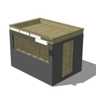
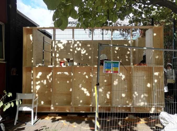
The result of these interconnecting boxes, left us with an approximate 4.2m x 2.8m water tight building, which can be easily disassembled, transported and re-built for an entirely new purpose and in an entirely new environment.
Whereby proving that such an alternative and innovative method of constructing can work effectively, and proving just how easily such a build can be put together, it will encourage future similar builds that can come together to promote a more sustainable and faster approach towards construction and usage of space.
23
Fig.37 - U-Build process
24 U-BUILD FRAME 2016
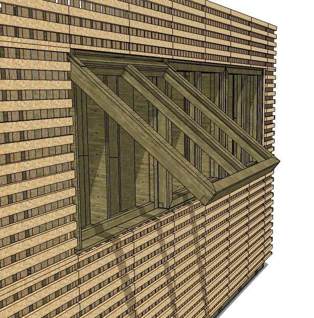
- Window Close-up
Fig.38
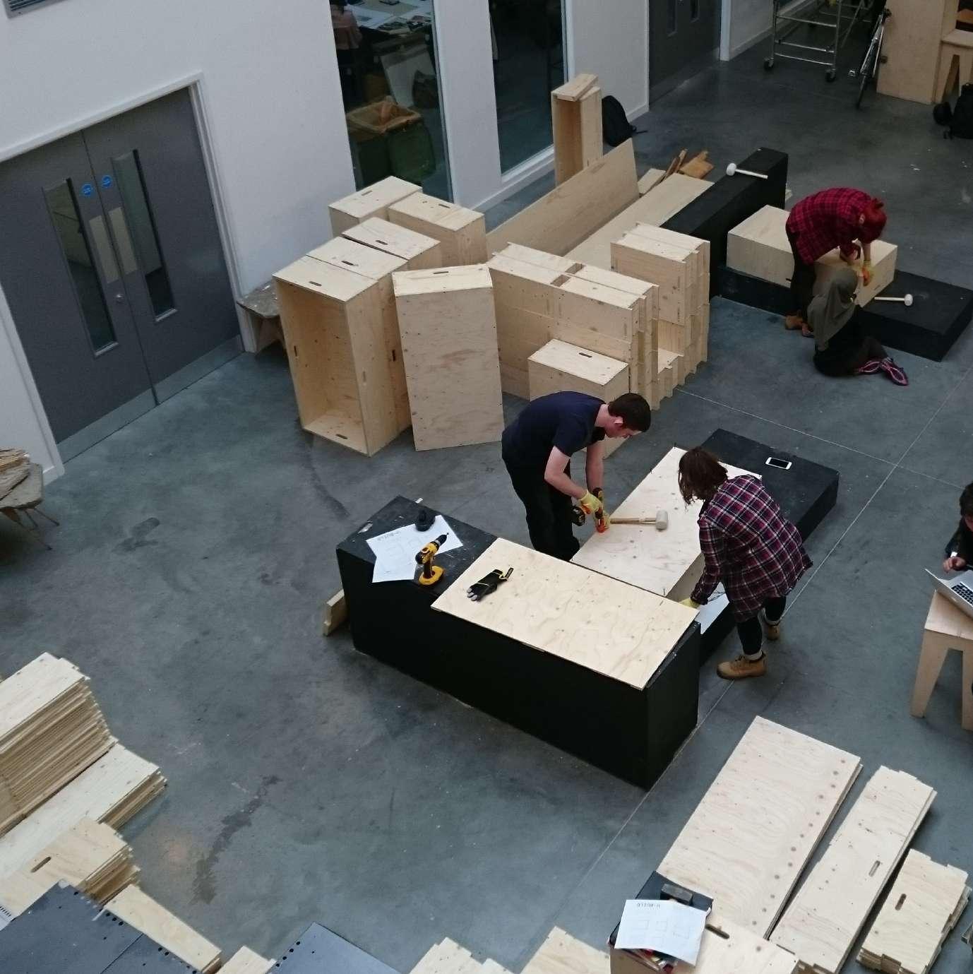
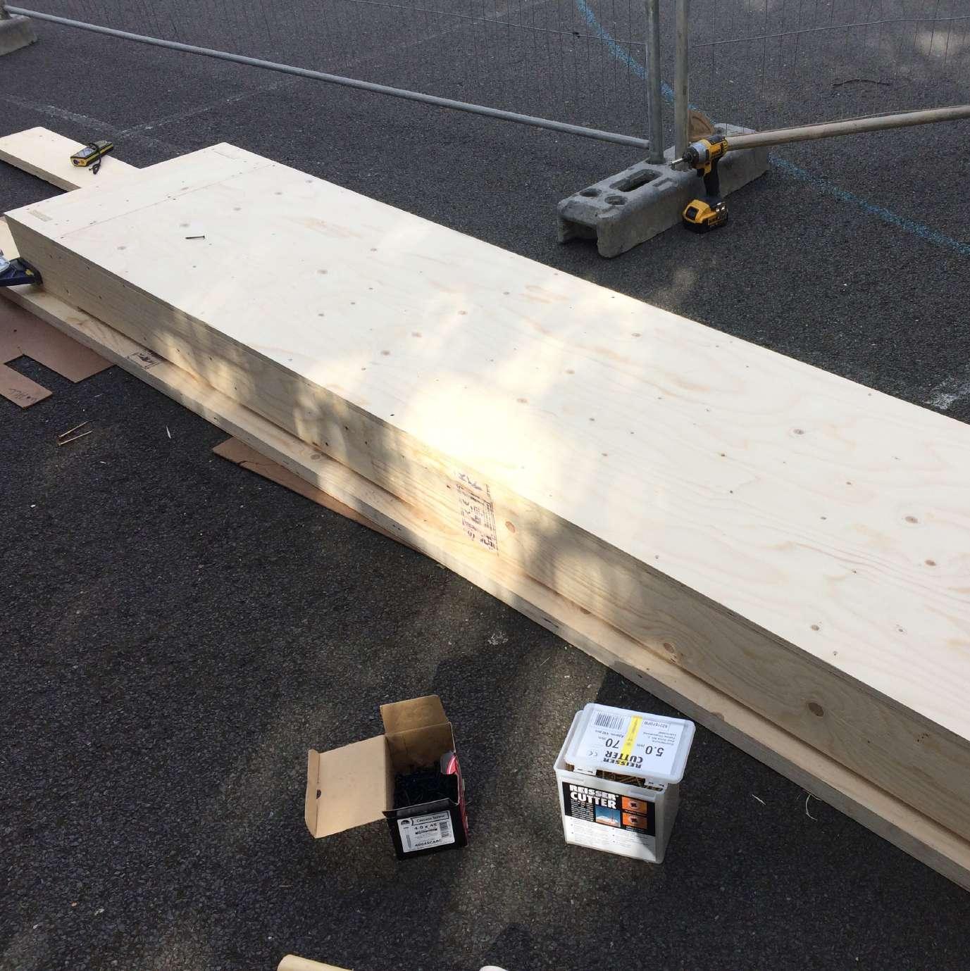
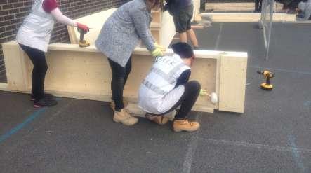
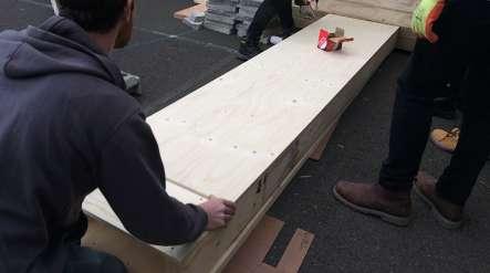
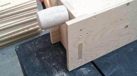
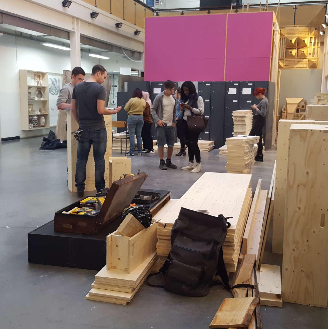
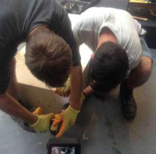
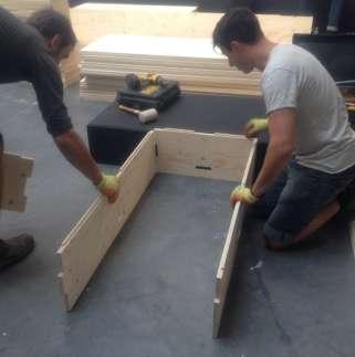
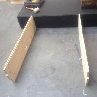
Each of the modular boxes were put together entirely by handwith the aid of an impact drill, a mallet and some screws. In order to simplify the tasks, we arranged each piece of timber into their own piles - depending upon size, in order to make finding each of the correct fitting parts as easy as possible and reduce over-all time wastage. Each box therefore, consisted of 6 piles.
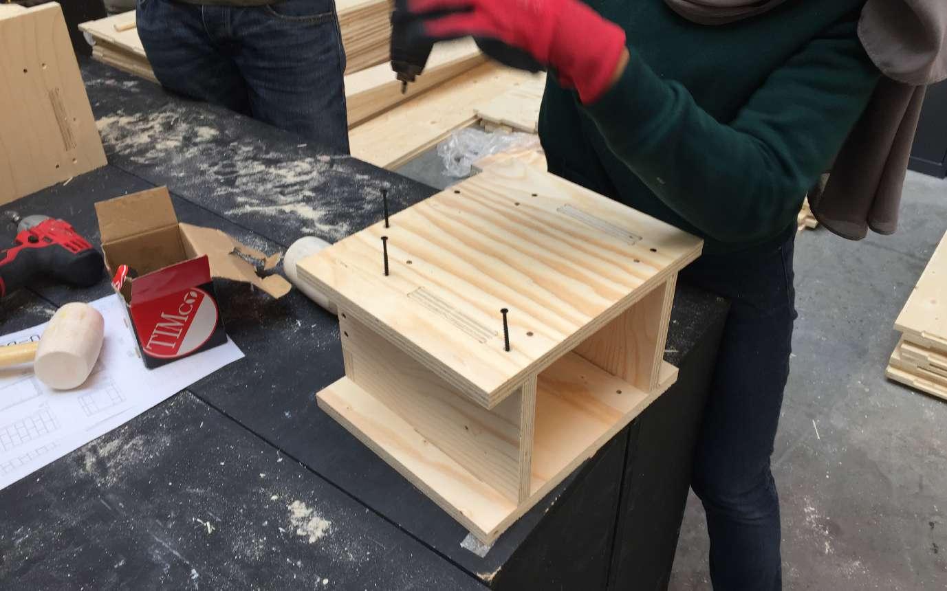
The process of forming the boxes was initiated by pre drilling the timbers at the points where marked, to allow a smoother run through of the screws at the later stage. Once all the timber pieces were pre-drilled, we began slotting them into eachother, using a mallet to ensure each of the corners are tightly pressed against eachother, and that there were zero gaps between the timber pieces. (As the importance of air tightness was vital)
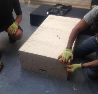
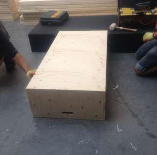
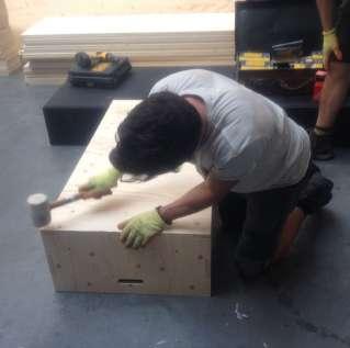
Once the box is formed, the next stage is to drill in the screws at each of the corner edges. Whereby alternating the order of which certain screws were drilled in, meant there was less chance of either
pieces of timber jolting in various directions. It was important that the pieces of timber alligned flush, as due to them being modular, we were aware that other boxes would need to sit above, below or either side of eachother as flush as possible. This process was repeated, until all 62 boxes were formed, leaving only the lids to be fixed after the insulation has been fitted.
The next stage of the process was filling in the insulation. The insulation was a vital element to the build, as we wanted to ensure we could create a well thermally insulated structure that wouldnt necessarily have to rely on another heat source.
Using an alligator saw, we were able to cut each of the bales of insulation down to size, depending upon the size of the boxes they were going in. To ensure an extra tight fitting, we cut the bales so that they were roughly 2cm larger than the actual box size. This was repeated, so that each box was tightly packed with two over-lapping pieces of insulation, to ensure the best thermal outcome.
25
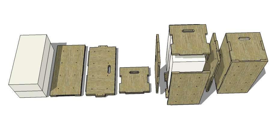
- Kit of Parts for one box unit
Fig.39
26 U-BUILD FRAME 2016
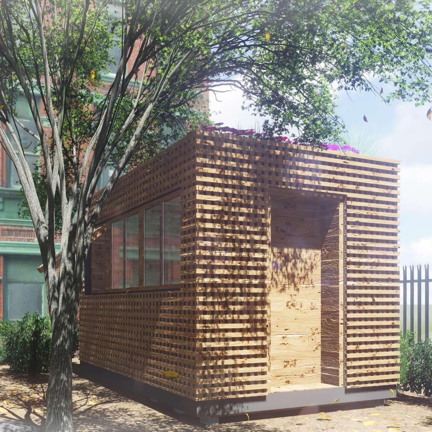
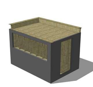
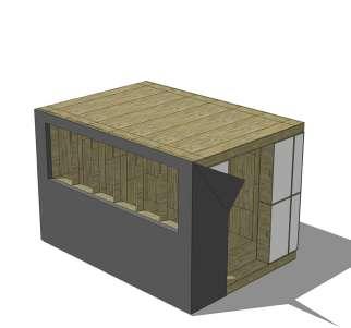
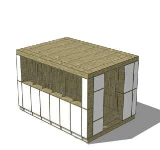
Fig.40
- Structure render
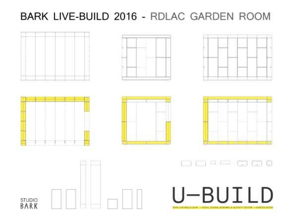
PROPOSAL DRAWINGS 4.1
27
Fig.42 - West Elevation
Fig.41 - North Elevation
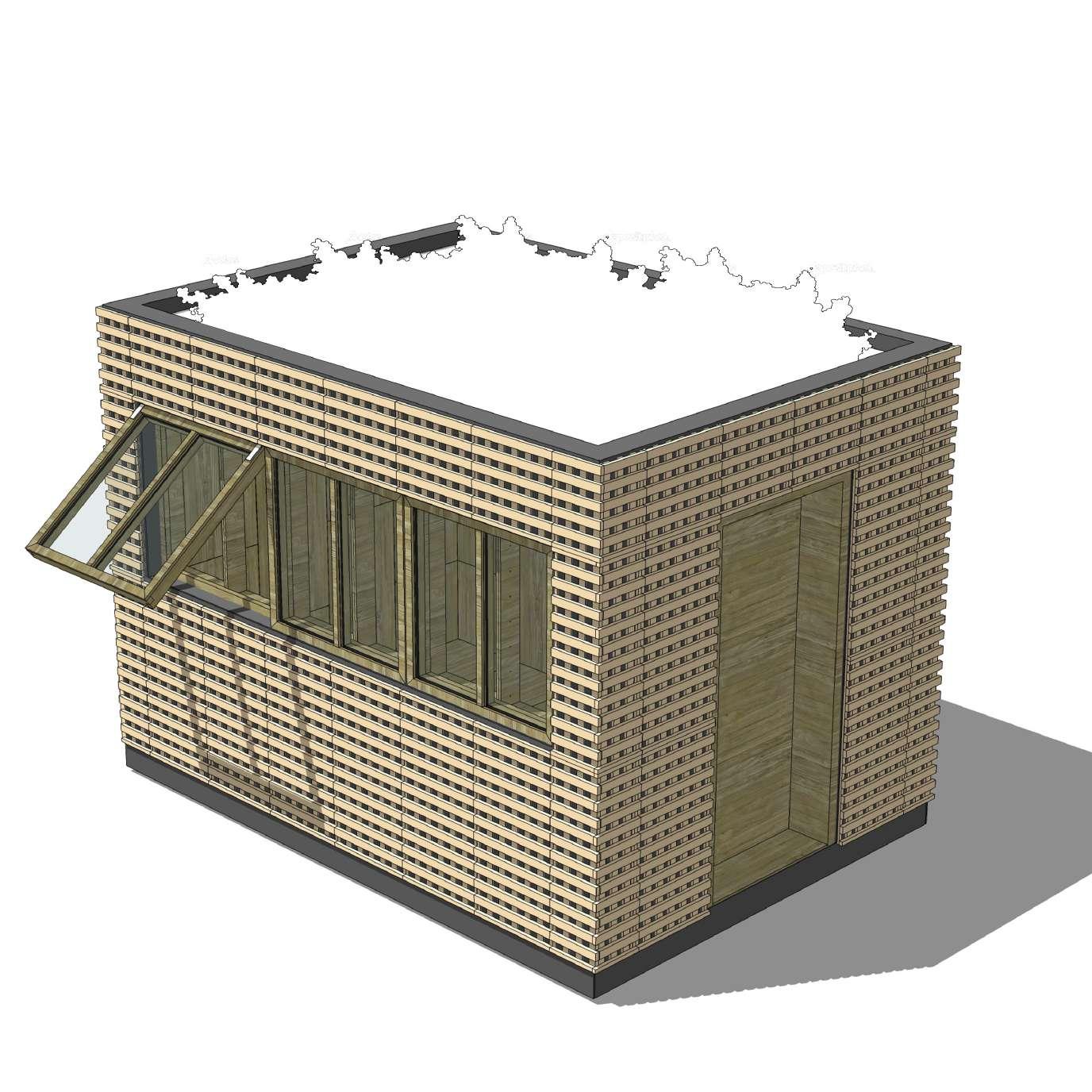
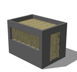
28 U-BUILD FRAME 2016 Fig. 43 - Completed structure
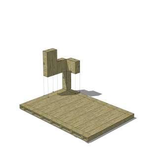
U-BUILD CONSTRUCTION PROCESS 4.2
29
Fig. 44 - Foundations
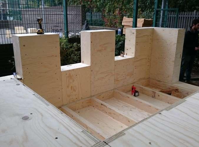
Fig. 45 - Installing floor boxes
Fig. 46 - Insulating floor boxes
Fig. 47 - Finished floor
Fig. 48 - Installing wall boxes
Fig. 49 - Installing wall boxes
Fig. 50 - Insulating wall boxes Fig. 51 - Installing roof boxes
Fig. 55 - Installing the parapet
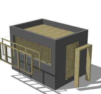
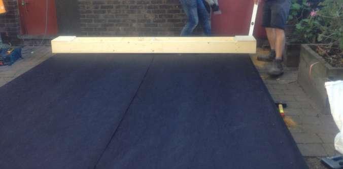
Fig. 54 - Wrapping the building in DPM
Fig. 52 - Insulating roof Boxes
Fig. 53 - Finished frame
Fig. 56 - Insulating the parapet
Fig. 57 - Wrapping the parapet in DPM
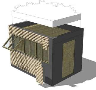
Fig. 58 - Installing windows and door
Fig. 59 - Installing cladding and green roof
30 U-BUILD FRAME 2016
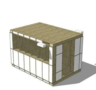
Fig. 60 - U-Build boxes
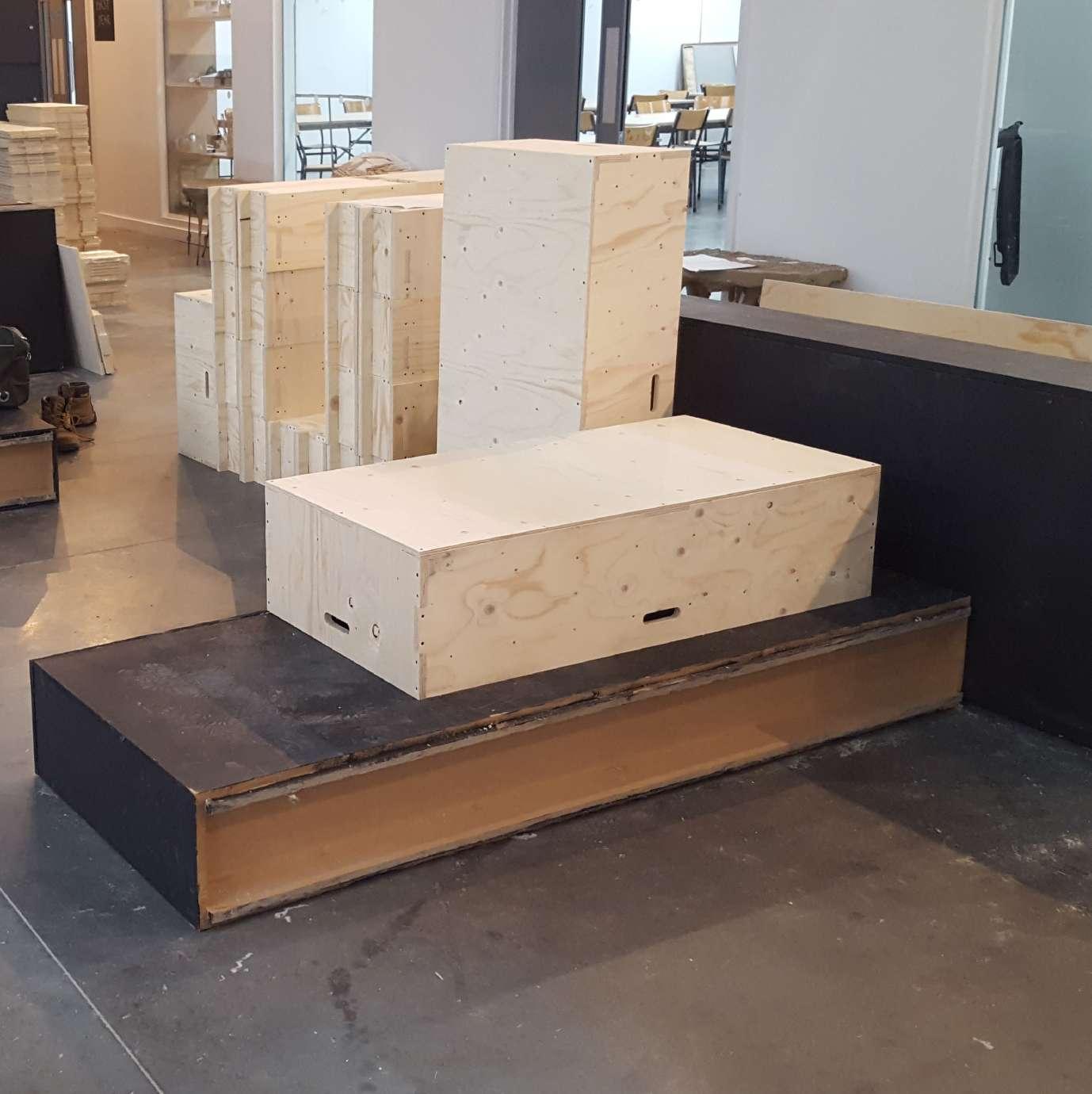
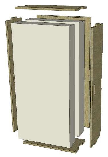
U-BUILD BOXES 5.0
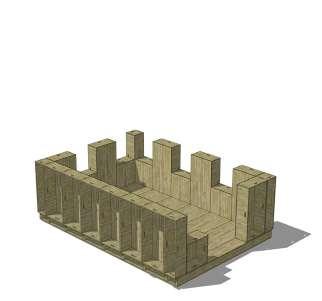
The structure was made using two types of boxes - floor boxes, which were also used as roof boxes, and wall boxes.
The design ensured that the boxes fit tightly together to contribute to the air tightness of the building. The boxes were kept together by bolts. The number of bolts was sought to respond to the optimal requirements, so that the thermal bridges are minimized.
The insulation inside the boxes was hay insulation, which is carbon negative, thus contributing not only yo the redusction of the heating requirements, but also to the reduction of the carbon by absorbing it and releasing of oxygen.
The boxes were allowed 0.5 mm tolerance when putting together.
31
Fig.61 - Box assembly
32 U-BUILD FRAME 2016
62
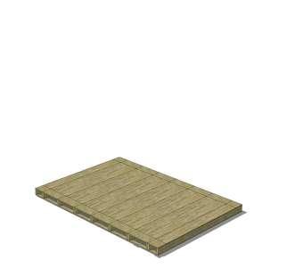
Fig.
- Floor Box
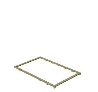
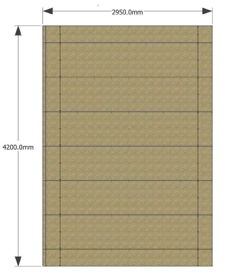
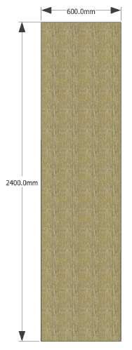
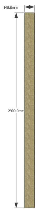
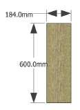
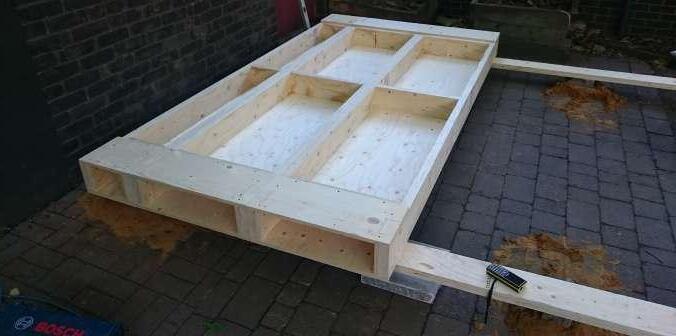
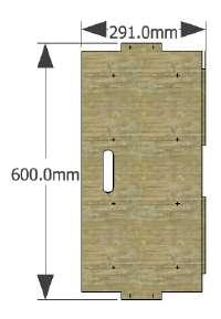
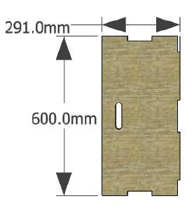
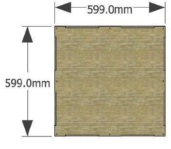
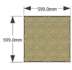
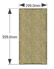
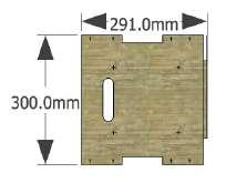
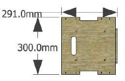
FLOOR BOXES 5.1
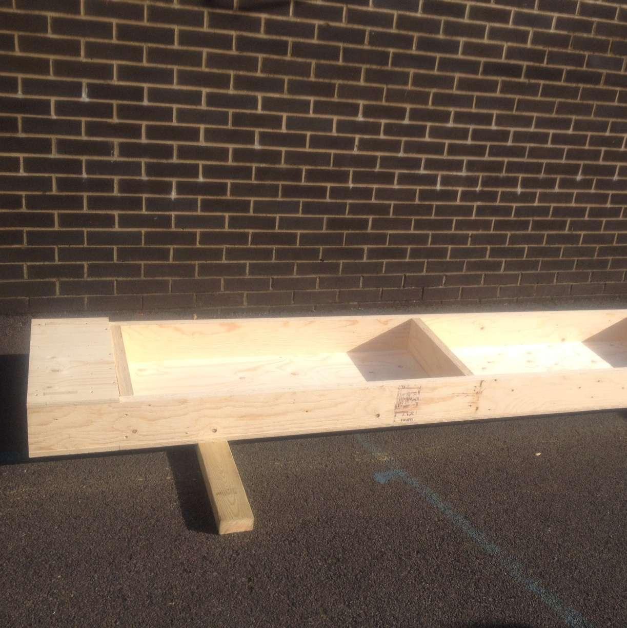
The floor was composed from 8 boxes. 6 wider for the central area and 2 narrower for the ends. They were fixed on a frame on top of the foundation with a vapour barrier between the frame and the boxes.
The floor‘s area is 4200x2950 mm.
33
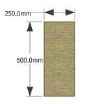
Wide floor box for the end of the floor
Narrow floor box for the ends of the floor
Fig.63 - Floor design
Side end
Side end
Insulation
Nogging
Insulation
Face
Face Side
Nogging
Insulation
Side
Nogging


Side end
Side end
Insulation
34 U-BUILD FRAME 2016
End End
Fig.64 - Ends
Fig.65 - Noggings Fig.66 -Side ends
Fig.67 - Face
Fig.68 - Sides
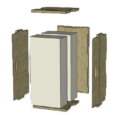
Fig.69 - Insulation
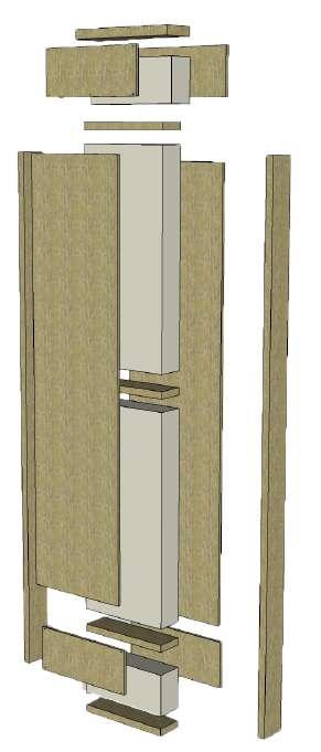
Fig.71 - Exploded box
ENDS NOGGINGS SIDE ENDS FACE SIDES INSULATION
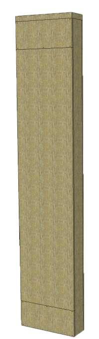
Fig.72 - Finished box
WIDE BOX
Fig.70 - Insulation
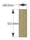
NARROW BOX
ENDS NOGGINGS SIDE ENDS
FACE
SIDES INSULATION
End
Side end
Side end
Insulation
Nogging
Insulation
Face
Face
Side
Nogging
Insulation
Side
Nogging
Side end
Side end
Insulation
End
35
Fig.73 - Ends
Fig.74 - Noggings
Fig.75 -Side ends
Fig.76 - Face
Fig.77 - Sides
Fig.79 - Insulation
Fig.80 - Exploded box
Fig.81 - Finished box
Fig.78 - Insulation
36 U-BUILD FRAME 2016
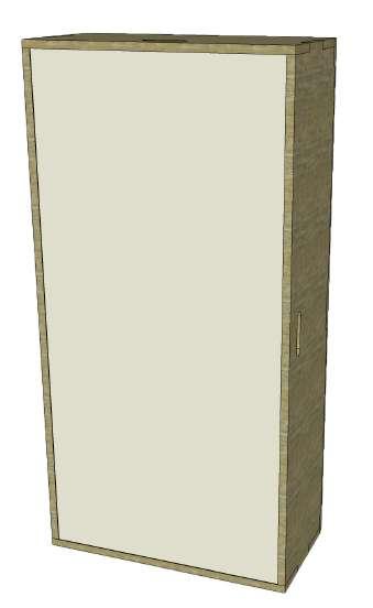
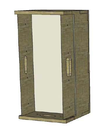
Fig.82 - Assembled floor box
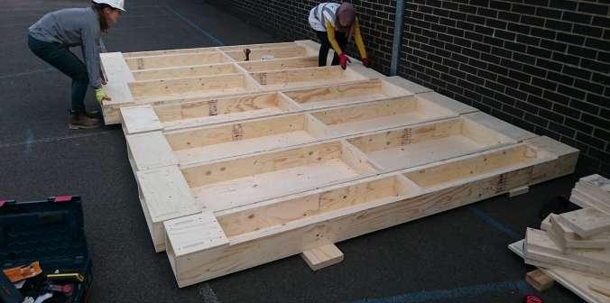
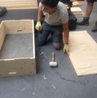
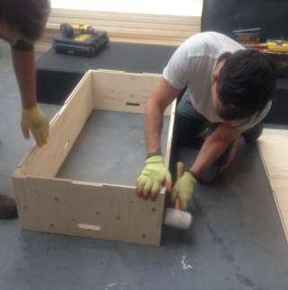
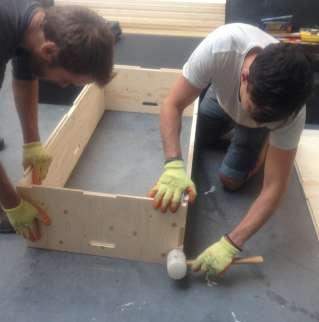
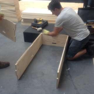
FLOOR BOX ASSEMBLY

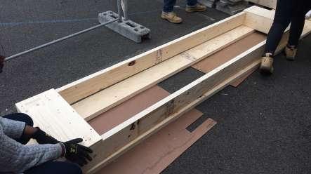

The boxes had to be put together by following a very precise procedure. First the ends were assembled, then the faces and one side of the box were fixed to them, with noggings inside. Insulation was added before fixing the last face, facing the interior of the Garden Room, after the boxes were fixed on the base frame.
All the boxes had to be executed very accurately so that they could work well with each other when they were assembled all together, to ensure airtightness and thus preventing heat loss.
37
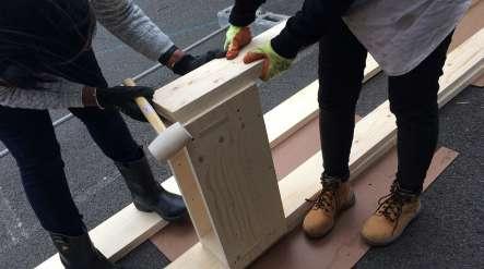
Fig.83 - Assembling the box
Fig.84 - Screwing the box together
Fig.85 - Screwing the box together
Fig.86 - Assembling the sides
Fig.87 - Assembling the sides
Fig.88 - Assembling the sides
Fig.89 - Assembling the sides
Fig.90 - Screwing the box together
Fig.91 - Attaching the face
Fig.92 - Attaching the face
Fig.93 - Attaching the face
Fig.94 - Fitting the noggings
38 U-BUILD FRAME 2016
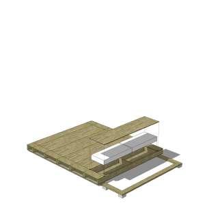
Fig.95 -Finished floor
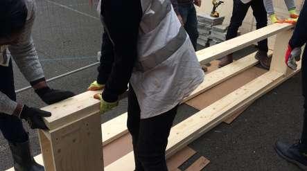
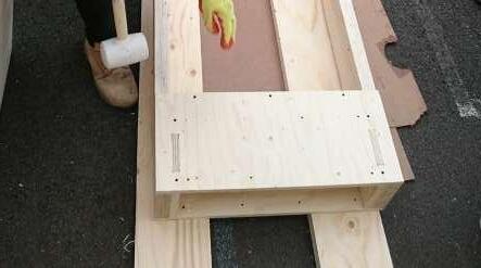
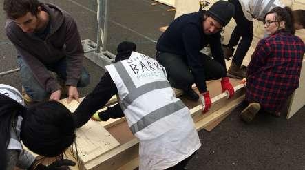
FLOOR BOX INSTALLATION
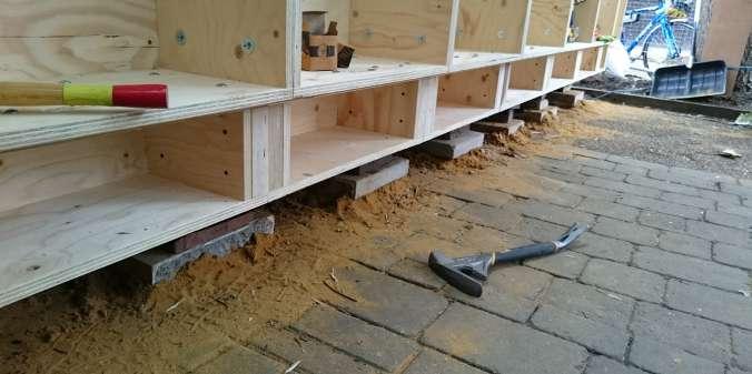
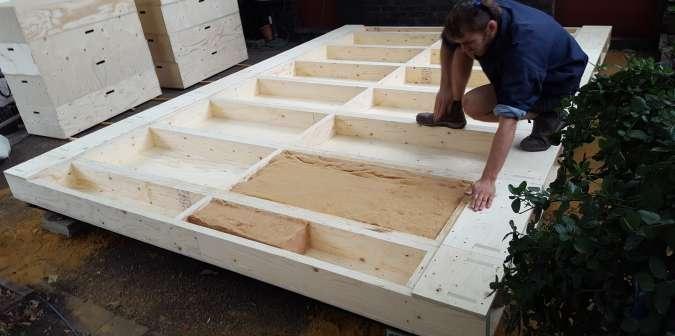
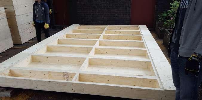
Once the boxes were ready they were tested to make sure they would fit and then started to be mounted on top of the base and vapour barrier. The narrow boxes were put on the ends of the floor with wider boxes filling the space between.
One of the main problems we had with the boxes, especially with
the narrow ones, was tightening the bolts at the extreme ends of the boxes, as there was not enough space to be able to use the tools. We ended up tightening properly only the ones we could have access to.
39
Fig.96 - Fitting the boxes
Fig.97 - Arranging the boxes
Fig.98 - Arranging the boxes
Fig.99 - Installed boxes
Fig.100 - Insulating the boxes
Fig.101 -Side view
40 U-BUILD FRAME 2016
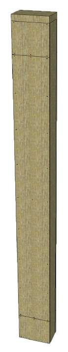
Fig. 102 - Wall boxes
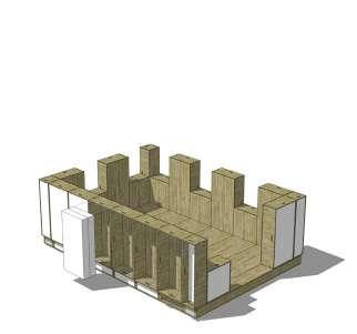
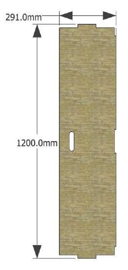
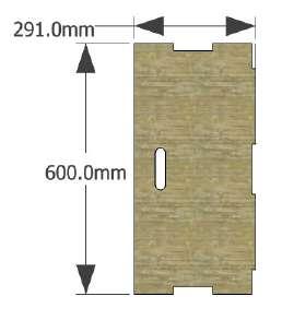
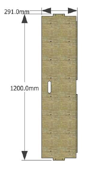
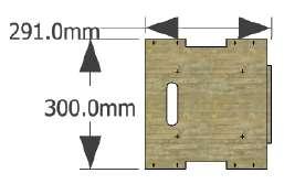
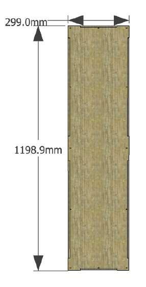
WALL BOXES 5.2
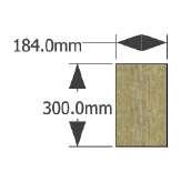
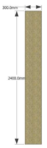
The walls were composed of four types of boxes: small squared boxes alternating with longer rectangular boxes, to ensure the height of the room, and small and long corner boxes.
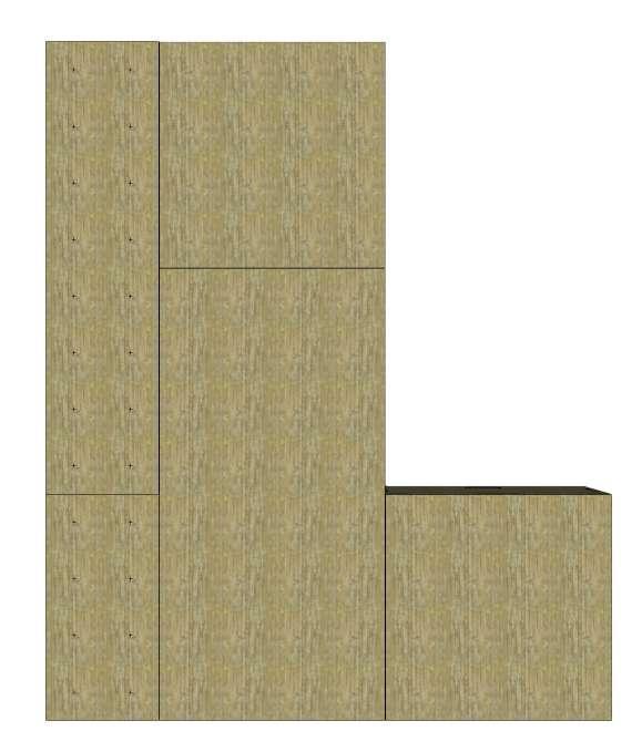
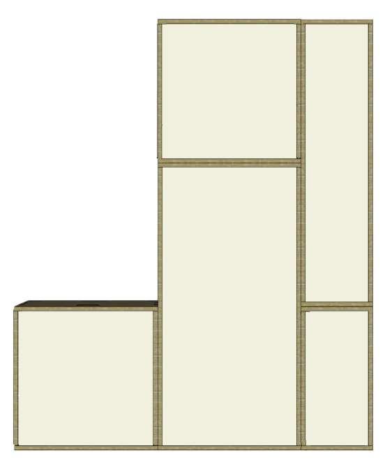
41
Small box
Long corner box
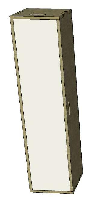
Long box
Fig.104 - Wall boxes external view Fig.103 - Wall boxes internal view
Small corner box
SMALL BOX
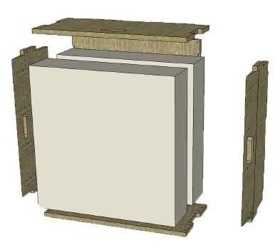
SIDES

FACE INSULATION
42 U-BUILD FRAME 2016 Side Side Face Insulation Side Insulation Side
Fig.105 - Small box side
Fig.107 - Small box face
Fig.108 -Small box insulation
Fig.109 - Exploded small box
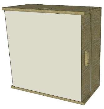
Fig.110 - Finished box
Fig.106 - Small box side
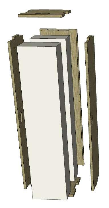
LONG BOX


SHORT SIDES
LONG SIDES
FACE INSULATION
Short side
Face Insulation
Insulation
Long side
Long side
Short side
43
Fig.111 - Long box short sides
Fig.112 - Long box long sides
Fig.113 - Long box face
Fig.114 - Long box insulation
Fig.115 - Exploded long box
Fig.116 - Finished box
SMALL CORNER BOX

SHORT SIDES FACE INSULATION
LONG SIDES
44 U-BUILD FRAME 2016
side Face
side Insulation
side
Short side Long
Insulation Long
Short
Fig.117 - Small corner box short sides
Fig.118 - Small corner box long sides
Fig.119 - Small corner box face
Fig.120 - Small corner box insulation
Fig.121 - Exploded small corner box
Fig.122 - Finished small corner box
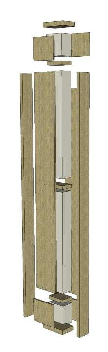
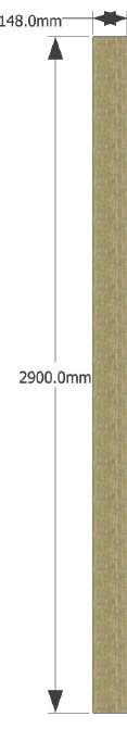
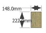
LONG CORNER BOX
Short side
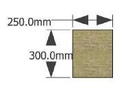
Face
Insulation
Insulation
Long side
Long side
Short side
45
Fig.123 - Long corner box short sides
Fig.124 - Long corner box long sides
Fig.125 - Long corner box face
Fig.126 - Long corner box insulation
Fig.127 - Exploded long corner box
Fig.128 - Finished long corner box
INSULATION
SHORT SIDES FACE
LONG SIDES
46 U-BUILD FRAME 2016
Fig.129 - Parts for boxes
WALL BOX ASSEMBLY

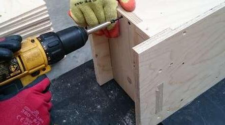
The boxes assembly required precision and following a certain procedure. The sides were put together first, the screws‘ ordes for each corner being 1-3-6, followed by 2-4-5, counting from the top hole. Then the bottom was fixed with first screws on the corners, then in cross and then the remaining ones.
47
Fig.130 - Introduction
Fig.131 - Step 1
Fig.132 - Step 2
Fig.133 - Step 3
Fig.134 - Step 4
Fig.135 - Step 5
Fig.136 - Step 6
Fig.137 - Step 7
Fig.138 - Step 8
Fig.139 - Step 9
Fig.140 - Step 10
Fig.141 - Step 11
48 U-BUILD FRAME 2016
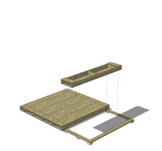
Fig.142 - Insulating the finished frame
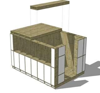
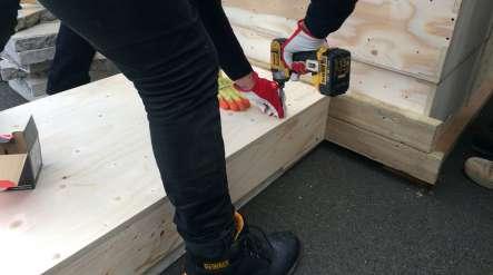
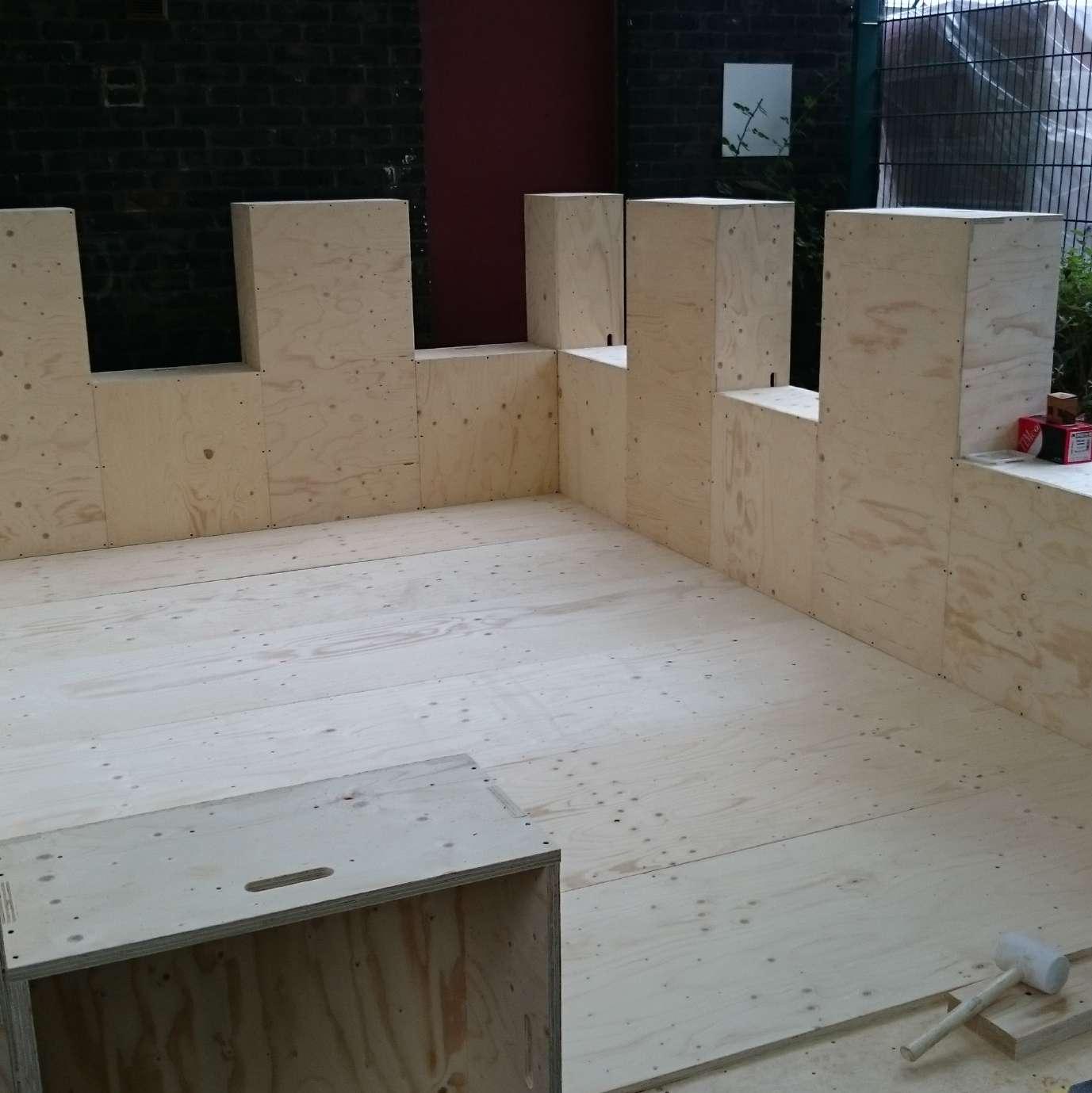
WALL BOX INSTALLATION
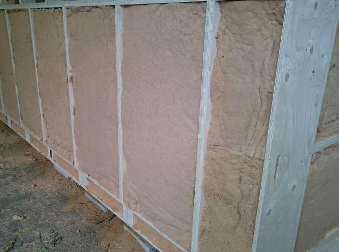
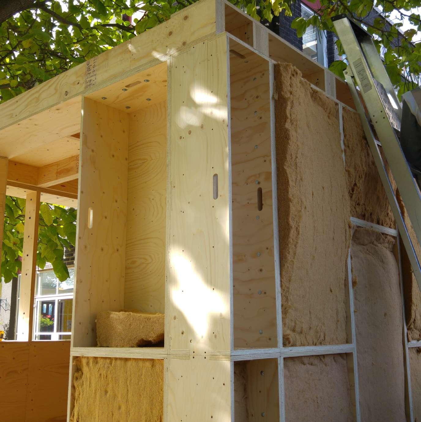
The walls were raised on top of the ends of the floor boxes, the square boxes alternating with the rectangular ones, with specific boxes for the corners. Bolts were used to put them together in as tight as possible, to ensure the air tightness of the room. The insulation was added at the end, before the DPM membrane was fixed to the walls.
The main problem encountered was to maintain the accuracy of the alignment of the boxes and it was also a little bit difficult to work at the back of the building as the space was very narrow.
49
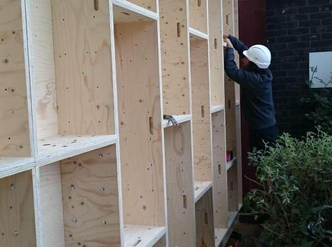
Fig.143 -Installing wall boxes
Fig.144 - Installing wall boxes
Fig.145 - Installing wall boxes
Fig.146 - Insulated wall boxes