21 minute read
Keys to Working With Phosphate Boiler Water Treatment Programs


Table B: Specifications for USP Monographed Waters (Effective with USP-NF 2020 (except as noted) USP Water Monographs
Attribute
Conductivity
Total Organic Carbon
Microbial Bacterial Endotoxins Particulates
Packaging Size
Relevant USP Test Chapter
<645>
<643>
<71> (for sterile waters only)
<85> <788>
Purified Water (bulk)
1.3 µS/cma
0.50 mg/L
None in monograph, but ≤100cfu/mL expected for mfgd
N/A N/A
N/A
Water for Injection (bulk)
1.3 µS/cma
0.50 mg/L None in monograph, but ≤10cfu/100mL expected for mfgd
Sterile Purified Water
25 µS/cmb 5 µS/cmb
32 mg/Lc 24 mg/Lc 8 mg/Lc
Sterile
< 0.25 EU/mL N/A < 0.25 EU/mL N/A
N/A No size limit
Sterile Water for Injection
25 µS/cmb 5 µS/cmb
32 mg/Lc 24 mg/Lc 8 mg/Lc
Sterile Water for Irrigation
25 µS/cmb 5 µS/cmb
32 mg/Lc 24 mg/Lc 8 mg/Lc
Sterile
< 0.25 EU/mL Meets test Not more than 1 L Sterile
< 0.25 EU/mL N/A
No size limit
Sterile Water for Inhalation
25 µS/cmb 5 µS/cmb
32 mg/Lc 24 mg/Lc 8 mg/Lc
Sterile
< 0.5 EU/mL N/A
No size limit
Notes:
a Stage 1 raw conductivity limit at 25° C. Different values at other temperatures. Stage 2 equilibrated limit is 2.1 µS/cm.
b 25 µS/cm is limit for containers with nominal volume of ≤ 10 mL and 5 µS/cm for containers with nominal volume of > 10 mL
c As of USP-NF 2021, Issue 1, effective May 1, 2021, these TOC specifications will become official. TOC is a two Limit specification, depending on 3 container size ranges. Limit 1 is 32 mg/L carbon for ≤ 5 mL containers; 24 mg/L carbon for >5 mL to ≤ 100 mL containers; and 8 mg/L carbon for >100 mL containers. If measured TOC is less than Limit 1, the test passes. If the measured TOC is greater than Limit 1, but less than the Limit 2 values of 48 mg/L, 36 mg/L, or 12 mg/L, respectively, then individual TOC contributing species present at > 0.20 mg/L carbon must be identified and patient toxicological safety referenced for the patient dose received of each identified organic species for the test to pass. If the contributing organic species cannot be identified or no toxicology information exists for one or more of the organic species or the measured TOC is higher than Limit 2, the test fails.
d A microbial specification is intentionally absent from these monographs since microbial content is typically irrelevant for some uses. But when used for manufacturing, regulators expect the testing of microbial samples from points of use to meet these limits or otherwise perform an OOS investigation. USP-NF Chapter <1231> has more discussion of this issue.
Steven Dunn, Process Performance Management LLC
Introduction The treatment of water in fossil-fired boilers using phosphate-based materials dates back to the early 1900s. The low feedwater quality at the time caused many boilers to fail because of heavy scale deposition. Calcium and magnesium scales formed on hot heat transfer surfaces, reducing energy transfer and creating conditions for metal failure as increased firing was required to overcome the thermal insulating properties of the scale.
These scales are exceedingly difficult to remove, as they are practically chemically inert and physically hard. Having the need to reduce costly boiler failures and to reduce extended downtimes for mechanical scale removal, experiments were started to create softer sludge materials by substituting sodium ions for calcium and magnesium ions (water softening). It was known that sodium materials were mechanically softer and more water soluble than their calcium/magnesium counterparts. At about the same time, it was determined that maintaining higher pH levels in the boiler water reduced iron-based metal corrosion (Figure 1).
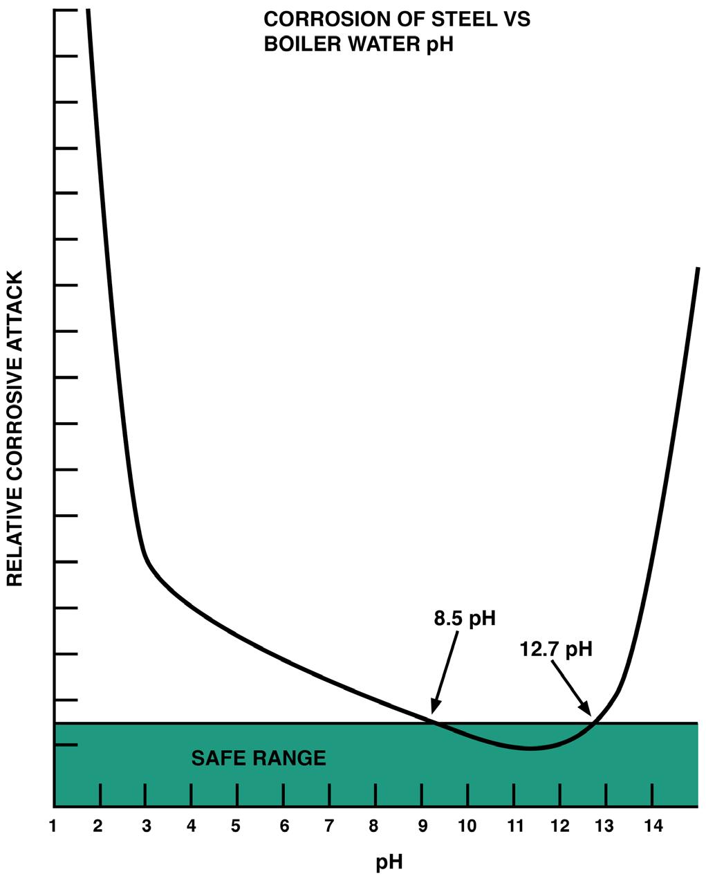
Figure 1: pH levels and their impact on metal corrosion.
Source: AdamMunich.com History of Treatment Approaches Experiments in the early 1900s centered on the use of sodium carbonate. The expectation was that the sodium carbonate would precipitate the calcium and magnesium as carbonate salts that could then be blown down. However, in actual practice, the precipitated carbonate salts tended to precipitate on the hot boiler internals like the previous calcium and magnesium oxides. Although the carbonate materials were easier to remove by chemical or mechanical means, it did not solve the deposition problem.
In the 1920s, experiments with combinations of sodium hydroxide and sodium phosphate were proving to be beneficial in reducing calcium and magnesium salt deposition. The calcium and magnesium formed a fairly soluble salt with the phosphate, allowing for most of the calcium and magnesium to be blown down. At the same time, the sodium hydroxide raised the pH of the boiler water into the minimum iron/steel corrosion range. This treatment process worked well in the low-pressure boilers of time; most were less than 800 pounds per square inch gauge (psig) operating pressure. Phosphate levels could be as high as 100 milligrams per liter (mg/L), and the pH, with the difficulty in analysis at the time, generally ranged from 9 to 13; hydroxide levels were not monitored or calculated.
In the 1930s and early 1940s, boiler pressures were increasing to as much as 1,500 psig. Boiler makeup treatment had greatly improved, so boiler deposit formation was no longer the primary cause of boiler failures, and corrosion failures started to take over as the principal cause of boiler failures. The low-pressure phosphate treatment parameters were brought forward and applied to these boilers. There were a number of catastrophic boiler failures due to caustic-induced stress corrosion cracking. Many steam drums at the time had riveted heads; stress around the rivets caused the steel to crack, allowing for large steam explosions in the powerhouse. Attempts were made to limit hydroxide concentration by adopting what were called conventional phosphate treatment standards: phosphate 30 to 60 mg/L, pH 11 to 12, and hydroxide 20 to 350 mg/L.
In the 1950s, boiler pressures continued to increase, and 1,500 to 1,800 psig was not uncommon. Boiler failures increased as the pressures increased and conventional
phosphate treatment standards were carried forward to these boilers. It was clear that phosphate treatment was not well understood and that increased research was required to reduce boiler failures. The concept of coordinating the sodium-to-phosphate ratio was introduced to try to reduce sodium hydroxide levels.
The phenomenon of phosphate hideout was also starting to appear, causing wild swings in boiler chemistry during pressure-change events. The new phosphate treatment program was called coordinated phosphate treatment. Phosphate was limited to 5 to 25 mg/L, pH to 9.0 to 10.5, sodium-to-phosphate ratio to 2.85:1 to 3.0:1, and hydroxide to a trace to a few mg/L.
These actions did reduce boiler failures until boilers again increased in pressure during the late 1960s and early 1970s, when boiler failures increased again. Boiler pressures were raised to as high as 2,400 psig. It was still thought that sodium hydroxide was the main culprit in boiler corrosion and that phosphate hideout, which had become a big problem by this time, was more of a nuisance than a cause of boiler tube failures. A treatment program called congruent phosphate treatment was introduced to reduce phosphate hideout and reduce hydroxide levels to near zero. Phosphate was limited to 2 to 5 mg/l, pH to 8.8 to 9.4, sodium to phosphate ratio to 2.3:1 to 2.6:1, and hydroxide to 0 to a trace.
Boiler pressures continued to increase during the 1980s to as high as 3,000 psig. Under congruent treatment, high-pressure boiler failures dramatically increased. In 1986, while trying to maintain congruent control, a drum boiler operating at 2,650 to 2,750 psig started showing extensive corrosion damage after only nine months of operation. After three years of operation, the boiler was nearly completely destroyed, requiring millions of dollars in repairs (see Figure 2).
Figure 2: Corrosion damage in a high-pressure drum boiler.
Source: B&W Plant Service Bulletin 25
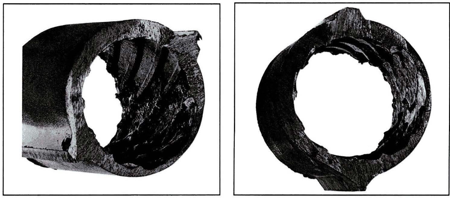
With hydroxide levels essentially zero under congruent phosphate treatment standards, something other than sodium hydroxide had to be causing the extensive corrosion damage. After considerable investigation, it was determined that the corrosion was caused by acidic phosphate conditions caused by low sodium-to-phosphate ratios and/or low pH from phosphate hideout return. The above boiler failure caused a great deal of re-examination of corrosion mechanisms in high-pressure boilers using phosphate treatments.
In the 1990s, phosphate treatment evolved to a concept called equilibrium phosphate treatment. To minimize the corrosive effects of low sodium-to-phosphate ratios and caustic conditions, the boiler is basically allowed to establish its own phosphate equilibrium between dissolved and solid phases. Phosphate levels were again reduced to minimize hideout effects, and sodium-to-phosphate ratios were strictly limited. With equilibrium phosphate treatment, boiler pressures are limited to about 2,200 psig. At pressures above 2,200 psig, all-volatile (ammonia) or oxygenated treatment has to be used because the solubility of phosphate above 2,200 psig is nearly zero. Under equilibrium phosphate treatment, phosphate levels are generally 0.2 to 3.5 mg/L and are allowed to drift with boiler pressure changes within this range, meaning the hard phosphate level requirements are gone. The pH range is 9.0 to 9.6 in conjunction with the sodium-to-phosphate ratio controlled to 3.0 to 3.0 +1 mg/L hydroxide. Specific and cation conductivity
should be controlled to 15 microsiemens per centimeter (µS/cm) or less.
Phosphate Characteristics Phosphate has reverse solubility: the higher the temperature, the lower the amount of phosphate that can be maintained dissolved in solution. If the amount of phosphate dissolved in boiler water is driven above saturation by increasing temperature, the excess phosphate forms a solid precipitate with the iron in the boiler. With every change in temperature, there is a new equilibrium established between the phosphate in the dissolved phase and phosphate in the solid phase. If there is a decrease in boiler water temperature, phosphate becomes more soluble, and some of the solid phosphate returns to the boiler water solution.
The phosphate equilibrium now shifts to more phosphate being dissolved in solution, with less phosphate being in the solid phase. This equilibrium shifting is commonly referred to as “phosphate hideout.” This is because the phosphate appears to hide out at high temperatures, only to return as the temperature drops. It is important to understand that there is always phosphate equilibrium between the dissolved phase and the solid phase in the boiler, depending on the temperature of the boiler water. With every change in boiler water temperature (higher or lower), there will be a change in the phosphate equilibrium to re-establish maximum solution solubility for phosphate.
Today, most boilers are only fed trisodium phosphate. Trisodium phosphate has a sodium-to-phosphate ratio of 3:1, which is three sodium atoms to one phosphate ion. When dissolved in water, one sodium atom is released from the trisodium phosphate compound and forms a sodium hydroxide molecule. This formation of sodium hydroxide molecules increases the pH of the solution, making the solution less corrosive to iron-based materials in the boiler (Figure 1). The pH of a 1% solution of trisodium phosphate dissolved in deionized water is approximately 12. A sodium-to-phosphate ratio of 3:1 in boiler water is highly desirable to prevent the formation of corrosive acidic phosphates while balancing against excessive formation of corrosive sodium hydroxide. However, when trisodium hides out, it does not return to the boiler with the same 3:1 ratio. Phosphate that hides out and returns generally has a sodium-to-phosphate ratio of 2.2:1 to 1.0:1. Low sodium-to-phosphate ratios are acidic, depressing the boiler water pH and increasing the corrosivity of the boiler water. The pH of a 1% solution of monosodium phosphate (a ratio of 1:1) dissolved in deionized water is approximately 4.2 to 4.8.
Sodium-to-Phosphate Ratios The sodium-to-phosphate ratio in the boiler determines if the boiler water will have corrosive phosphate conditions. The lower the sodium-to-phosphate ratio, the more corrosive the boiler water solution becomes. To minimize corrosive phosphate or corrosive caustic conditions, current recommendations are to maintain the sodium-to-phosphate ratio between 3.0:1 and 3.0:1 + 1 mg/L sodium hydroxide. Figure 3 shows a sodium-to-phosphate ratio chart compiled from data from the Electric Power Research Institute and the International Association for the Properties of Water and Steam publications.
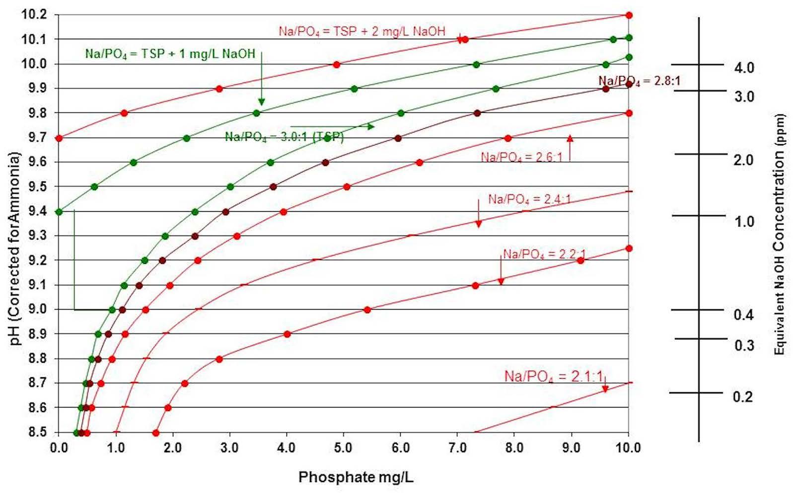
Figure 3: Sodium-to-phosphate ratio chart.
Figure 4 is a more simplified version of the Figure 3 chart, showing the corrosive areas that should be avoided to minimize corrosion in the boiler.
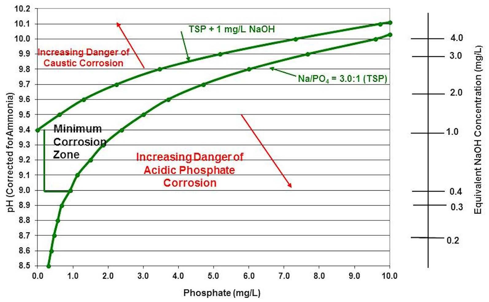
Figure 4: Simplified sodium-to-phosphate ratio chart.
Figure 5 is a chart that illustrates what happens to the sodium-to-phosphate ratio when phosphate increases in the boiler water with no change in boiler water pH. Note that the sodium-to-phosphate ratio is driven into acidic phosphate ranges, thereby increasing the potential for corrosion in the boiler.
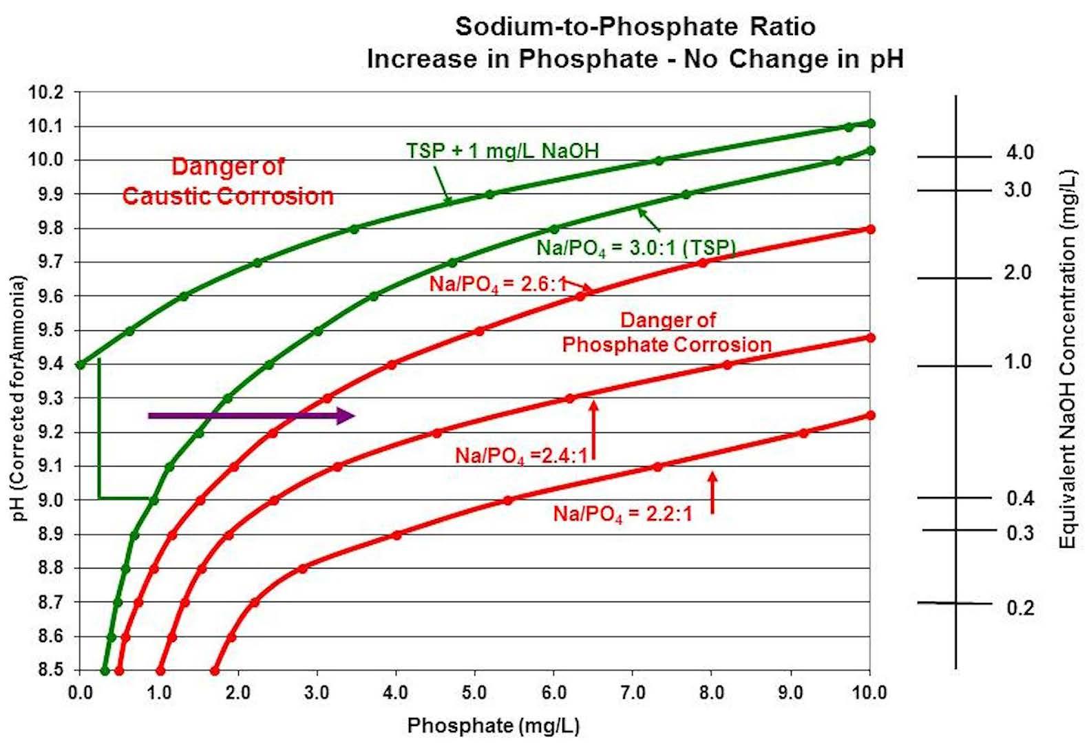
Figure 5: How increases in phosphate levels in boiler water impact the sodium-to-phosphate ratio.
What is generally observed during a drop in boiler pressure/temperature hideout incident is illustrated in Figure 6. As the pressure/temperature drops, phosphate that was “hiding out” is able to return to the boiler water due to the increased solubility of lower temperature water. Because the returning phosphate has a sodium-to-phosphate ratio less than 3.0:1, the acidity of the returning phosphate depresses the boiler water pH. The chemistry equilibrium is shifted from being in the minimum corrosion zone to being in the corrosive phosphate zone. The quickest way to restore the boiler water chemistry to where it was at the start is to increase the temperature/pressure back to the original values. The phosphate will again hide out, lowering the phosphate in solution, and the pH will rise as sodium is freed up to form sodium hydroxide.
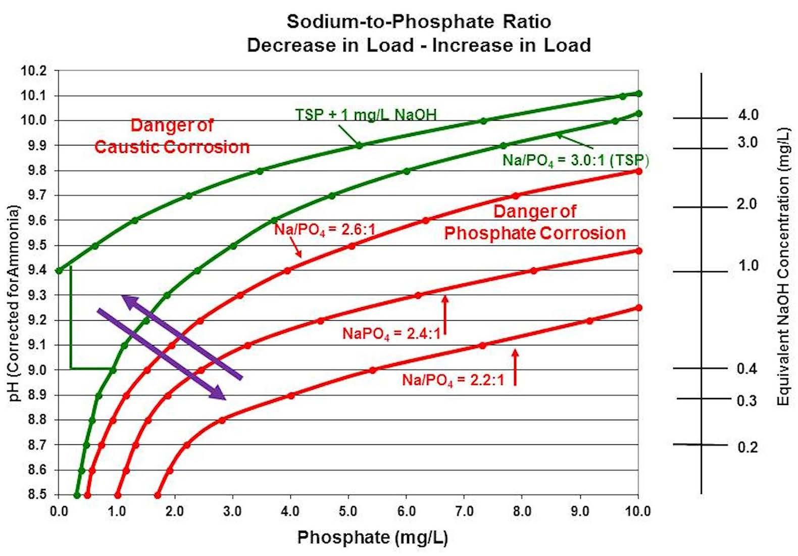
Figure 6: How a drop in boiler pressure and temperature generally impacts boiler water chemistry.
Chemists and/or operators frequently try to respond to the low-pH condition by increasing the feed of trisodium phosphate. Trisodium phosphate can increase the pH back within limits, but the undesirable effect will be the increase in phosphate. Due to the increase in phosphate, the sodium-to-phosphate ratio may never reach the minimum corrosion zone. If the boiler then returns to the previous temperature/pressure, phosphate will hide out, freeing up sodium that will form sodium hydroxide, causing the pH to rise, possibly high enough to push it into the caustic corrosion range, requiring the boiler to be blown down to restore the boiler chemistry back to the starting point. If there are frequent boiler load swings, the chemist and/or operator can find themselves caught in an endless cycle of feeding chemicals and opening the blowdown to try to respond to a constantly shifting chemistry equilibrium (see Figure 7).
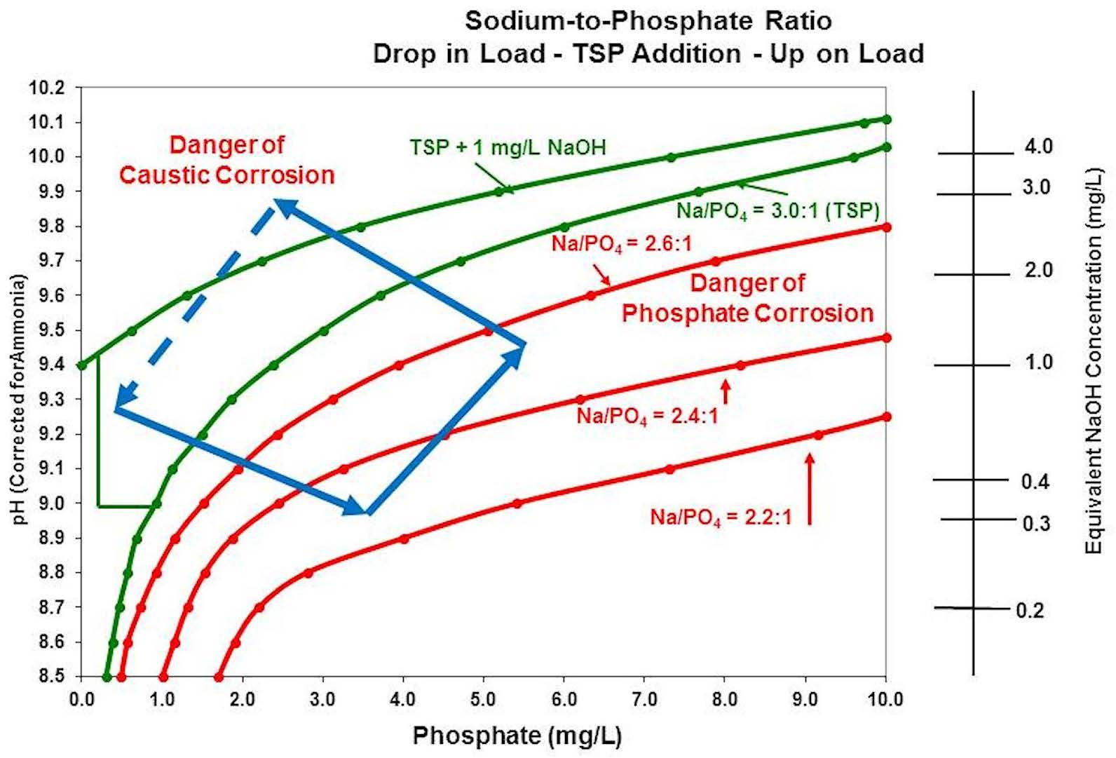
Figure 7: Effect of attempting to correct boiler chemistry conditions during a load reduction by the addition of trisodium phosphate.
Chemists and/or operators may also try to correct a low-pH condition by adding a sodium hydroxide spike to the boiler. Although this is a better method for correcting the chemistry than adding trisodium phosphate (no increase in phosphate from the chemical feed), corrosive chemical conditions may not be eliminated. If the boiler then returns to the original pressure/temperature, phosphate will hide out, freeing up sodium that will form sodium hydroxide, raising the pH, possibly raising the pH high enough to be in the caustic corrosion zone, where the boiler has to be blown down to return to the original chemistry point. If the boiler pressure/temperature remains stable, however, excess phosphate can be blown down while remaining within the minimum corrosion zone as the pH and phosphate levels will drop in coordination. But as before, if there are frequent boiler load swings, the chemist and/or operator can find themselves caught in an endless cycle of feeding chemicals and opening the blowdown, trying to respond to constantly shifting boiler water chemistry (Figure 8).
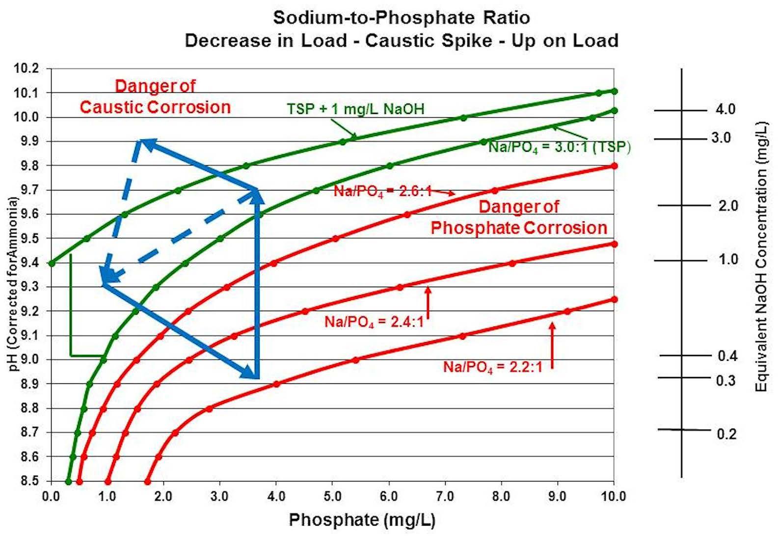
Figure 8: Effect of correcting boiler chemistry conditions during a load reduction by the addition of sodium hydroxide.
Figure 9 is an actual case where a sudden reduction in temperature/pressure took the boiler on a wild chemistry journey deep into the acidic phosphate zone and then when the pressure/temperature returned, into the caustic corrosion zone before being returned back within control limits. Note that the incident occurred over a period of 104 hours—approximately 4.3 days— in 1998. During most of that time, the boiler chemistry was in a corrosive condition, either acidic phosphate or caustic. As shown on the chart, before the incident started, the chemist/operator was raising the pH of the boiler water, most likely using trisodium phosphate. Because the boiler was at high-pressure/temperature, little phosphate was able to stay dissolved in solution. Any phosphate added during this time immediately formed a solid precipitate with the iron on the surface of the boiler steel components.
When the pressure/temperature sharply dropped, large quantities of phosphate were able to re-dissolve in the boiler water, causing the pH to be depressed by the low sodium-to-phosphate ratio of the returning phosphate. The chemist/operator may have tried to recover the pH by feeding even more trisodium phosphate, which would have added even more phosphate to the boiler, shifting the phosphate equilibrium further in the wrong direction. As the pressure/temperature started to increase, phosphate started to hide out, freeing up sodium that became sodium hydroxide, which in turn started raising the pH. As the pressure/temperature continued to increase, most of the phosphate in solution hid out again with the freeing up of more sodium, forming additional sodium hydroxide and causing the pH to be pushed up into the caustic corrosion zone. Blowdown was then most likely used to drop the pH back within the minimum corrosion zone.
While the boiler was in acidic phosphate conditions, below 2.2:1, iron would have been rapidly dissolving (corroding) into the boiler water solution from the boiler steel components. As the pH started to rise, the iron would have become more and more insoluble, forming solid deposits on the boiler steel components. The deposits would not have been uniform, as heavier deposits would have formed in high heat transfer zones, as compared to cooler areas of the boiler.
Above pH 9, almost all the iron that had been dissolved would now be solid deposit on the boiler components. As the boiler water pH was driven into the caustic corrosion zone, sodium hydroxide could have formed under the iron deposits, causing corrosive conditions to remain under the deposits long after the bulk boiler water
returned to normal chemistry. Due to the underdeposit isolation from the bulk water, chemistry conditions under deposits can be vastly different than the chemistry in the bulk water. This single incident could have set up the boiler for many future boiler-deposit-related component failures, including underdeposit corrosion, hydrogen damage, caustic gouging, and long-term overheating damage. This is why it is important to maintain boiler chemistry conditions within the minimum corrosion zone as much as possible.
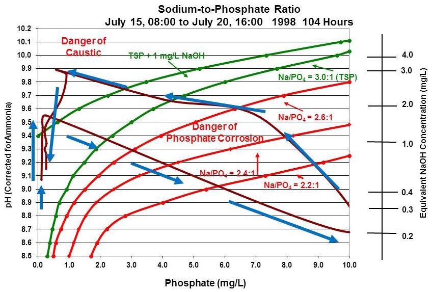
Figure 9: Example where sudden reduction in temperature and pressure sent boiler water chemistry into an out-of-control situation.
Achieving Minimum Corrosion Conditions Because modern power plant boilers generally have high-pressure temperature conditions, only a small amount of phosphate is able to remain dissolved in the boiler water, generally 0.2 to 1.5 mg/L. Trying to force the boiler to higher levels than what the temperature equilibrium will allow causes the excess phosphate to hide out. With any change in boiler pressure/temperature, new phosphate equilibrium will be established between the dissolved phase and the solid phase. To minimize phosphate hideout effects, the phosphate level should not try to be forced above the pressure/temperature equilibrium level. Attempting to force the dissolved phosphate level above the pressure/temperature equilibrium point, will only cause the phosphate to hide out and increase the chemistry effects in the boiler water when the hideout returns. The boiler phosphate level should be allowed to drift (within reason) to changes in phosphate equilibrium caused by pressure/temperature changes. Phosphate additions should be avoided during boiler pressure/ temperature changes to prevent pushing the sodium-to-phosphate ratio into corrosive regions. It is recommended that sodium hydroxide be used to control the boiler water pH, so that additional phosphate will not be added above the phosphate equilibrium point, increasing phosphate hideout. The pH of the boiler water
should only be lowered through the use of blowdown. The addition of acidic phosphate (monosodium phosphate) to lower the boiler pH should never be used, as boiler corrosion rates will increase dramatically.
The boiler water phosphate level should be maintained at the equilibrium level only by the addition of trisodium phosphate. The use of other phosphate materials may cause unintended chemical excursions. The phosphate equilibrium point can be determined by feeding phosphate until there is no increase in dissolved phosphate, indicating that any additional phosphate added will hide out. Avoid chasing the boiler chemistry during pressure/ temperature changes as much as possible. Chemistry additions during boiler pressure/temperature are likely to make chemistry conditions worse. Experience has shown that a continuous feed chemical tank mixture of four parts sodium hydroxide to one part trisodium phosphate will generally keep the boiler water chemistry within the minimum corrosion zone. Over time, the mixture can be fine-tuned to keep the boiler chemistry in the center of the minimum corrosion zone.
For accurate boiler water chemistry corrosion zone evaluations, the boiler water pH should be corrected for the ammonia in the boiler feedwater. It is the solid alkalinity portion of the measured pH that is required to accurately determine where the boiler chemistry is located on the sodium-to-phosphate ratio chart. If the boiler water is being monitored for cation conductivity, the cation conductivity has to be corrected for the phosphate at about 2 µS/cm per 0.5 mg/L of phosphate. The phosphate converts to phosphoric acid when passing through the instrument resin column, causing the reading to be high. Summary There are a number of advantages to boiler water phosphate treatment:
The boiler feedwater can be oxidizing or reducing.
Acid-forming anions (chloride and sulfate) are neutralized by the sodium in the solution.
Scale-forming cations (calcium and magnesium) tend to form softer phosphate scales as opposed to oxide scales.
Some pH buffering occurs due to the weak acid/ contingent base reactions of the phosphate.
There is some protection from sodium hydroxide carryover in steam provided by the phosphate distribution ratio in steam.
The principal disadvantages of boiler water phosphate treatment are:
Phosphate hideout return, possibly creating corrosive chemistry conditions in the boiler due to low pH and/ or low sodium-to-phosphate ratios.
Possible iron phosphate deposition under certain conditions due to solid alkali feed to the boiler.
Remember that there is always an equilibrium between the phosphate dissolved in the boiler water and the phosphate that is in solid form with the iron in the boiler that is determined by the pressure/temperature of the boiler at any given point in time. Be aware that any changes in boiler pressure/temperature will cause the phosphate equilibrium to shift, possibly moving the boiler chemistry into corrosive conditions.
Bibliography
Babcock & Wilcox (1994). “Boiler Water Phosphate
Chemistry,” plant service bulletin, Babcock &
Wilcox, Barberton, Ohio. Baghni, M.; Zwebek, I. (2009). Using of Congruent
Phosphate as Equilibrium Phosphate Boilers Water
Treatment, Wit Press, Southampton, U.K., ISSN 1743-3509. Buecker, B. (November 2015). “Steam Generating
Chemistry: Correcting Outdated Beliefs and
Misconceptions,” Power Engineering 119(11). Buecker, B. (2000). Fundamentals of Steam Generation
Chemistry, PennWell Corp., Tulsa, Oklahoma,
ISBN 10: 0-87814-750-0. Christophersen, D. (February 2004). “History of
Industrial Water Treatment,” originally published in
CSTN. EPRI (2011). "Comprehensive Cycle Chemistry
Guidelines for Fossil Plants" (1021767), Electric
Power Research Institute, Palo Alto, California.
C
M Steve Dunn is a semi-retired (2014) power Y plant chemist still consulting part time on CM power plant chemistry issues. He has more MY than 45 years of experience in managing coal-fired power plant boiler, pre-boiler,
CY
and cooling water system chemistries. Mr. CMY
Dunn has authored a number of presentations for power
K
plant chemistry conferences and several magazine articles over the years. He graduated from Peru State College (Peru, Nebraska) in 1980 with a B.S. in physical science. Mr. Dunn can be reached at sdunn@ppmconsults.com.
This paper was originally presented at the Electric Utilities Chemistry Workshop as a PowerPoint presentation, June 4–6, 2019, in Champaign, Illinois.
BULK SYSTEMS, INC.
Though�ul products for the water treatment industry Revolu�onary Design 65 Gallon Capacity Flooded Suc�on DikeTank
Unique design feature of this double walled tank is that it safely allows you to avoid loosing prime in your pump by pumping from the bo�om without any risk of catastrophic spill.
This truly innovated design is the result of over thirty years of working with companies in the Water Treatment Industry. We know what you want. Flooded Suc�on, Safety, and Smart Looking. Bulk Systems, Inc. does it again.
Contact us for more informa�on at: email: doug@bulksystemsinc.com Phone: 847 546-3113