63 minute read
Biofilm Monitoring: A How-To Guide for Practical Cooling Water Management

AWT Cooling Subcommittee Representatives: John Caloritis, CWT (The Metro Group, Inc.); Keith Johnson (Keith M. Johnson Consulting); Richard Rosser, Ph.D. (AMSA, Inc.); Derrick Vandenberg, CWT (Guardian Chemicals Inc.)
(Editor’s note: This report on biofilm monitoring is based on a research project conducted by AWT’s Cooling Water Subcommittee. The listed authors are all members of the subcommittee.)
Introduction Biofilm is a disruptive force that accelerates corrosion, deposition, and fouling in open cooling water systems. It contributes directly and indirectly to waterside corrosion through the various mechanisms of MIC (microbiologically influenced corrosion). Mineral and suspended solid deposition become more likely and more tenacious in the presence of biofilm, as heat transfer rates suffer. Finally, biofilm presence affects overall microbial control and encourages the proliferation of waterborne pathogens, such as Legionella.
While the importance of the impact of biofilms on water systems is understood, and water treatment programs increasingly are structured to control biofilm growth, limited information is available to guide water treatment professionals on how to conduct the types of biofilm testing that can be used to assess and optimize biofilm control efforts.
This article, which is based on a six-month program of biofilm monitoring method evaluation at four industrial facilities, addresses this lack of information on practical field techniques available to confirm, quantify, and monitor the presence of biofilm. It describes the methods deemed to be the most technically appropriate, with relevant focus on these areas: Biofilm collection Field testing Data interpretation
The study used three biofilm analysis methods to quantify the presence/activity of biofilms that developed on four different test surface types exposed in two passive monitoring devices. The analyses were conducted on 30-day biofilms collected in six monthly sampling events at four testing locations. 30-day intervals are considered a minimum timeframe necessary to develop a mature biofilm.
Adenosine triphosphate (ATP) (total and free) and dipslides were used to monitor planktonic microbial populations in the waters of the industrial water systems during visits to the locations for biofilm testing. Efforts were made to avoid sampling immediately after system biocide treatments, but no other modifications to the chemical treatment programs applied in these systems were made.
Two testing methods—ATP and an enzyme-based biofilm presence/activity method called “HMB®”—were shown to reproducibly detect biofilm in the field. The ATP and HMB® methods for biofilm detection are described in this article. Experience with a biofilm stain method that was included in the study is also discussed. These detection methods focused on the use of portable strategies that could readily be carried out in the field, and whose methods were already somewhat familiar to AWT members.
To summarize, the article will show that a standard corrosion coupon rack can be used to adequately collect biofilm in a bypass arrangement and that stainless-steel coupons provide a suitable and technically appropriate biofilm collection surface that supports analysis by the ATP and HMB® methods. These allow for sample collection to occur conveniently, consistently, and reproducibly.
Background In 2018, AWT’s Cooling Water Subcommittee launched a workgroup project to study various field-based biofilm monitoring techniques. The work focused on studying passive biofilm collection strategies coupled with the use of available biofilm field-testing techniques.
A primary objective was to study methods that could be completed on a typical cooling water service visit, and without reliance on an external laboratory for testing. The study included a six-month testing program conducted in four very different water systems to evaluate the selected biofilm collection equipment and analysis methods. The water systems included two building heating, ventilation, air conditioning (HVAC) systems on city water makeup, one facility HVAC system on high suspended particulate solids river water makeup, and one industrial process water system with high suspended particulate solids.
A detailed summary report on the findings of the study was issued in September 2019 and is available to AWT members in the members-only section of the AWT
website (“Practical Field Use of Biofilm Collection and Analysis Tools,” available at https://www.awt.org/ members-only/cooling-resources/). The report provides insights and observations in a comparative format on equipment and supplies needed to collect and analyze biofilm growth, explains the steps required to set up and conduct a biofilm testing program, and details the costs (equipment, consumables, hours) to conduct the testing. It allows the reader to draw conclusions about both the availability of field techniques, as well as the reproducibility and success rates of the methods selected for study.
Tools of the Biofilm Monitoring Trade Biofilm monitoring tools are used to assess the presence and/or activity of microbial biofilms in any water system. These can include “active” monitoring devices that measure and report in real time some physical or activity-related characteristic of the biofilm microbial population, and “passive” monitoring devices, which use retrievable surface samples to collect biofilm for quantitative analysis. The cost and complexity of active monitoring devices makes them suitable for use mainly in large industrial systems. For this reason, we have focused on passive biofilm monitoring devices and analysis methods that are suitable for medium and small industrial or HVAC water systems.
Biofilm Collection Devices
Two “passive” biofilm monitoring devices were evaluated in the study: 1. A standard off-the-shelf corrosion coupon rack; and 2. A six-port Modified Robbins Device (MRD) from Tyler Advanced Corrosion Technologies (Figure 1a). The MRD, model MPMR-CB06PVC, is a medium pressure (100 pounds per square inch [psi]) device made of polyvinyl chloride (PVC) and homopolymer acetal thermoplastic that accommodates six metal studs as removable biofilm growth surfaces (Figure 1e). When installed in the device, the stud surfaces are approximately flush with the pipe wall and therefore experience the same flow conditions as biofilms on an inner pipe surface. The studs used in this study were 316 stainless steel, with exposed surface area of 0.147 square inches (in2).
The coupon rack and MRD were installed with the coupon rack immediately upstream of the MRD. Standard conditions and precautions for installation and operation of corrosion coupon racks as outlined
in AWT corrosion monitoring guidelines (“AWT Recommendations and Guidelines for Corrosion Coupons in Cooling Systems”) were followed.
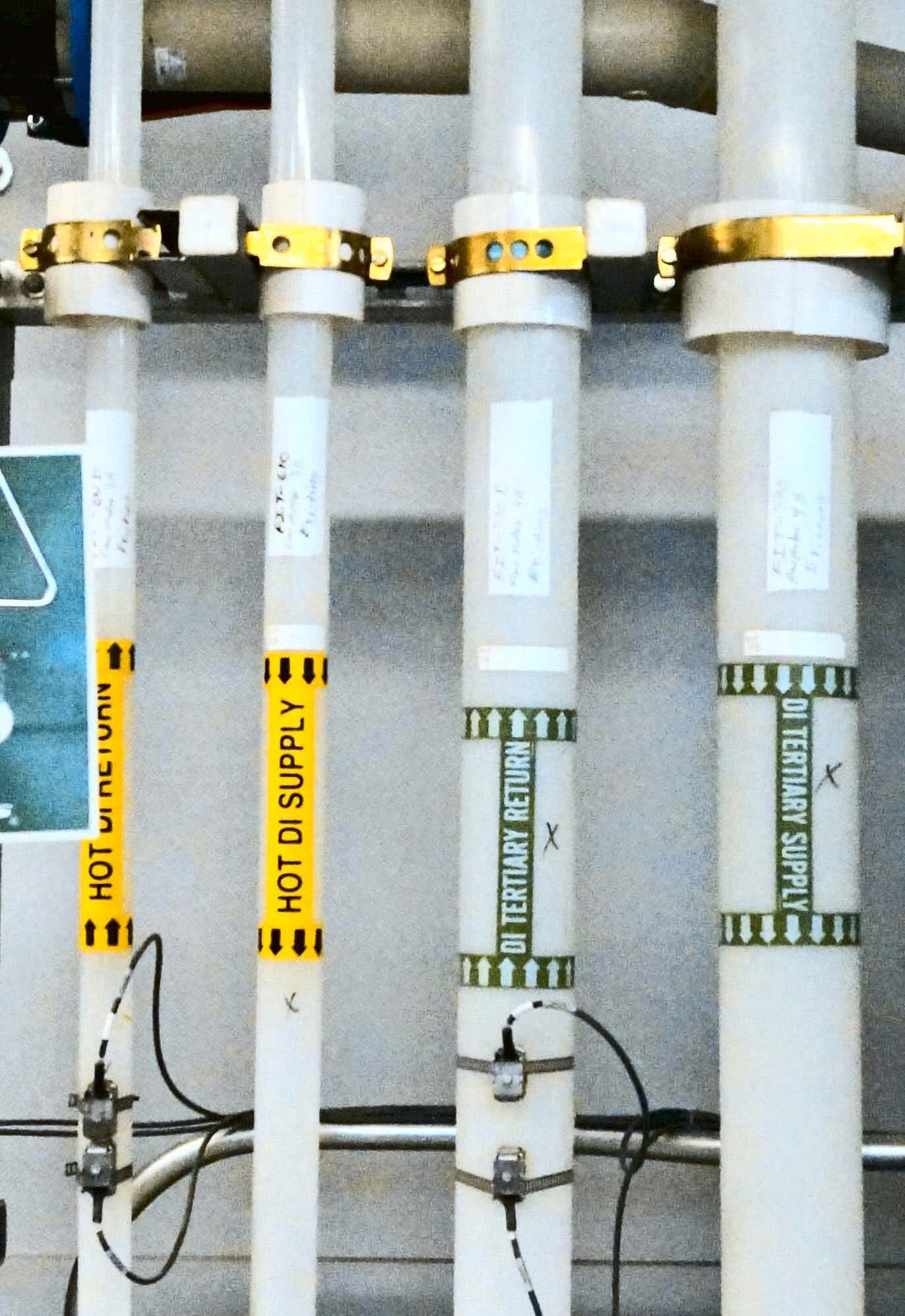
Figure 1: Passive biofouling monitoring devices and retrievable coupons and studs: (a) Corrosion coupon rack (lower) and MRD (upper); (b) Stainless-steel coupon; (c) Stainless-steel mesh coupon; (d) Perforated polycarbonate coupon; and (e) MRD and MRD stainless-steel studs.
MRD
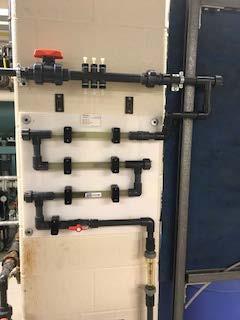
Coupon Rack
(a)
(b)
(c)
(d)
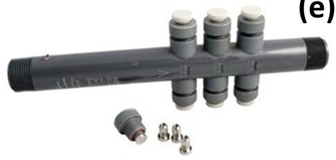
(e)
The coupon rack was fitted with three types of coupons: standard stainless-steel strip type coupon, stainless-steel mesh “biofilm” coupon, and perforated polycarbonate coupons (supplied with the HMB® test kit), all with dimensions similar to standard corrosion coupons (Figures 1b, 1c, 1d, respectively). Some coupons were installed with two coupons on one holder. The MRD was fitted with six identical stainless-steel studs.
Evaluation of the Biofilm Collection Tools The biofilm collection tools were evaluated at the four locations by four water treatment professionals in a program of six monthly biofilm growth-sampling-analysis cycles, with all coupons and studs retrieved and analyzed after an exposure period of approximately one month. Based on these experiences, the following conclusions were drawn by participants in the study.
Both the corrosion coupon rack and the MRD performed reliably under the installation and operating conditions chosen for the program. Both devices allowed for the growth of biofilms on the test surfaces installed in the devices. However, based on six months of experience operating both devices, corrosion coupon racks were preferred over the MRD device for exposing samples for biofilm growth/monitoring. This preference was based on familiarity with operation of corrosion coupon racks, the ability to use an existing rack to conduct biofilm monitoring, and the lower cost of the coupon rack compared to the MRD device, as well as the additional care required when working with the small, cylindrical MRD studs.
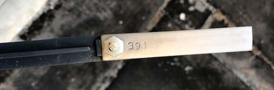
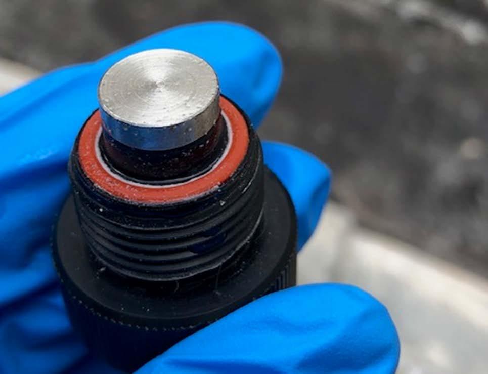
Stainless-steel coupons and stainless-steel MRD studs (Figure 2) allowed for the growth of biofilms at all locations. Despite their much smaller surface area, MRD studs provided enough biofilm for analysis by all biofilm methods employed in this study at all testing locations. However, the physical manipulation of the stud holders and studs during removal, sampling, and reinstallation
was found by all users to be challenging and a potential source of sample contamination and error.
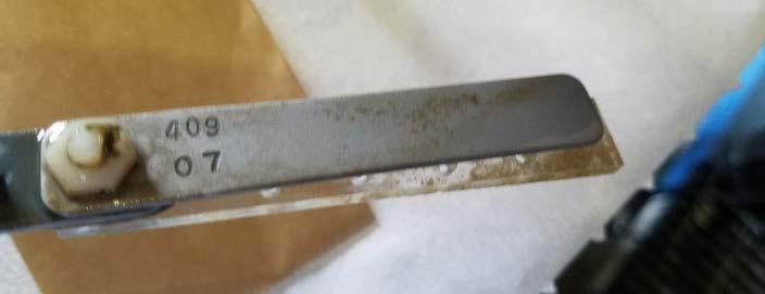
Figure 2: Stainless-steel strip type corrosion coupons (top) and stainless-steel MRD studs (bottom) provide suitable surfaces for monitoring biofilm growth.
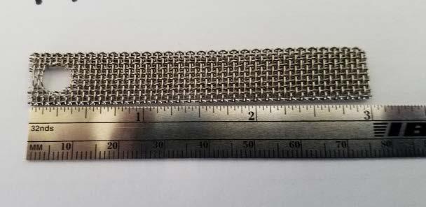
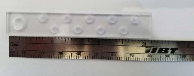
The perforated polycarbonate and stainless-steel mesh coupons allowed for the growth of biofilms at all locations, but also allowed accumulation of biomass-contaminated debris in systems with high suspended particulate solids, resulting in artificially elevated indications of biofilm presence (Figure 3). The perforated polycarbonate coupon is suitable for systems with low suspended solids. The mesh coupon is best used as a visual, nonquantitative indicator of biofilm presence.
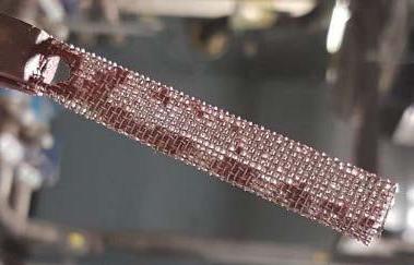
Figure 3: Stainless steel mesh coupon.
Why might you choose to use a relatively expensive MRD? The value of analyzing replicate biofilm samples
(multiple MRD studs versus single coupons) was apparent in the data collected. The natural “growth – detachment – regrowth” cycle of biofilms, compounded by the application of biocides and/or dispersants in industrial water systems, produces a level of variability in biofilm samples that makes testing of replicate samples at each testing event valuable for identifying high or low outlier results. Without analyses of replicate samples, there is significant risk that important treatment decisions will be made based on a single outlier biofilm test result.
By consensus, a standard strip-type stainless-steel coupon, exposed in a standard corrosion coupon rack, is the preferred biofilm collection device. Biofilm from a defined surface area of these coupons can be easily collected and analyzed for biofilm presence or activity as part of a routine site visit by the water technologist.
Biofilm Assessment Methods Several commercially available biofilm assessment methods were considered for evaluation in this study. Criteria for selection of the assessment methods were as follows:
1. Suitable for onsite analysis to minimize changes during sample transport/storage.
2. Limited sample processing prior to analysis to minimize operator influence/error.
3. Quantitative results by direct instrument readout preferred.
4. Reasonable analysis time to minimize service visit time.
5. No specialized microbiology techniques or skills required.
6. Reasonable quality equipment and supplies required to be brought to the site.
7.
8. Reasonable cost (instrument and per test).
Minimal waste generated from testing.
Based on these criteria, the three biofilm assessment methods chosen for evaluation were ATP, the HMB® test, and the HydroBio® biofilm stain. A summary of each method is provided here.
ATP. ATP is a key energy-carrying molecule in all living cells and has been widely used for many years as an indicator of the presence of microorganisms in liquids and on surfaces. ATP is measured by an enzymatic method that generates light in proportion to the amount of ATP present in the sample. The light is measured in a hand-held “luminometer” (Figure 4), with results reported as RLU (relative light units) per sample (e.g., per milliliter for liquid samples, per coupon/ stud or per square centimeter for surface samples). For biofilm samples, a cotton swab sampler is used to collect biofilm from a defined surface area. The sampling swab and reagents used in biofilm ATP analyses in this study are supplied as a single device (“UltraSnap™ pen”) by the luminometer manufacturer, Hygiena, LLC. ATP analyses of water samples conducted in this study used Hygiena AquaSnap™ Total ATP and Free ATP pens.
HMB® . The HMB® test, developed and manufactured by BioTech International Inc. (Figure 5), is based on measurement of peroxidase enzyme activity in a liquid or surface (biofilm) sample. Peroxidases are enzymes found in all aerobic organisms and organisms exposed to oxygen. Microbial peroxidase activity is described in the HMB® test manufacturer’s literature as an indicator of the overall level of metabolic activity in a biofilm or liquid sample. The presence of peroxidases (e.g., catalase) can be detected by the breakdown of hydrogen peroxide with the evolution of oxygen. The HMB® biofilm test measures an increase in oxygen partial pressure in the test vessel headspace resulting from the decomposition of hydrogen peroxide by peroxidases associated with biofilm-based organisms. A perforated polycarbonate coupon (Figure 1(d)) supplied with the HMB® test materials is recommended for use in biofilm testing. The test involves transferring a coupon with biofilm (or a surface swab biofilm sample) to a tube containing a small amount of hydrogen peroxide, which is then sealed. After 15 minutes the sealed tube is connected to the HMB® instrument which measures the increase in oxygen partial pressure in the headspace, providing results in “BMR” (BioMass Readout) units. Literature provided with the HMB® testing system states that readings less than 0.27 BMR units are considered insignificant, whereas readings greater than 4.0 BMR units indicate the sample is heavily contaminated.
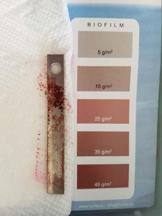
HydroBio® Test. The HydroBio® biofilm detection test kit from Kurita (Figure 6) is based on a biofilm staining method. Biofilm is allowed to develop on a stainless-steel coupon in a corrosion coupon rack. The coupon is removed from the coupon rack and exposed to rinse and biofilm stain solutions. Stain is retained in proportion to the amount of biofilm present, and the intensity of the stain color is compared to a color comparator chart which provides results as grams of biofilm per square meter of surface area (5 to 45 gram per square meter [g/m2] in 5 g/m2 increments). The method differs from the ATP and HMB® assessment methods in that it provides a measure of the mass of biofilm present on the coupon, rather than the activity of the microbial community present in the biofilm on the coupon.
These three biofilm assessment methods are applied to whole biofilms and will detect the presence of nearly all biofilm organisms. Biofilm assessment by viable count of dispersed biofilm microorganisms was not included in the study due to well-known difficulties achieving complete and reproducible biofilm dispersion in the field, and the selectivity of viable count growth media that results in detection of a small fraction of the total microbial population present in environmental samples.
The three selected biofilm analysis methods were used in the study as follows: ATP swab pens were used to quantify biofilm ATP on stainless-steel strip-type coupons from the coupon rack, and on MRD studs from the MRD. The HMB® method was used to assess biofilm peroxidase (enzyme) activity on perforated polycarbonate and stainless-steel mesh coupons from the coupon rack, and on swabs of MRD studs or whole MRD studs from the MRD. Finally, the HydroBio® biofilm stain was used to quantify biofilm biomass associated with stainless-steel strip type coupons from the coupon rack, and on MRD studs from the MRD.
Figure 4: Hygiena System Sure ATP Illuminator (top) and (bottom) an example of an ATP pen.
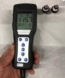
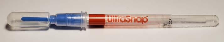
Figure 5: HMBX instrument and vials with rubber septum (left). Septum is pierced by needle (right) with connection
to an oxygen sensor in the HMB® instrument.
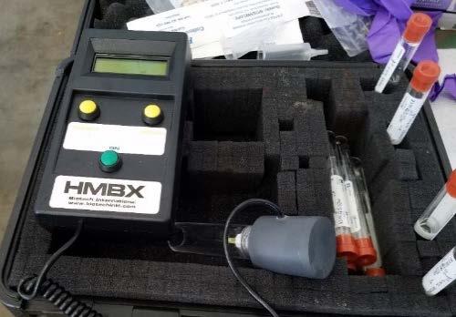
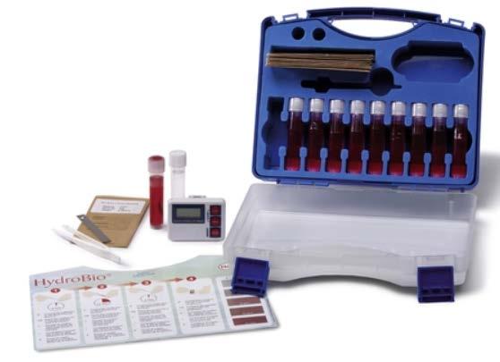
Figure 6: The HydroBio® Test Kit includes stainless-steel coupons, vials containing stain and rinse solutions, a timer, and a color comparator relating color intensity to biofilm mass.
Figure 7: An example of the HydroBio® test kit. These kits include stainless steel coupons, vials containing stain and rinse solutions, a timer, and a color comparator relating color intensity to biofilm mass.
Evaluation of Biofilm Assessment Methods The ATP and HMB® biofilm test methods, as applied in this study, were able to assess the presence and/or activity of one-month biofilm populations from four water systems.
Sampling and analysis of biofilm ATP on stainless-steel coupons and MRD studs using the UltraSnap™ Surface swabs were rapid (approximately 2 minutes) and completed without difficulty. ATP results were straightforward to read and interpret. ATP analyses of replicate MRD studs demonstrated particularly good reproducibility at three of the four testing locations. Comparison of biofilm ATP results with the results of ATP analyses of water samples were consistent with the well-documented concept that measures of planktonic microbial population size/activity, including Cell-ATP and Free-ATP, are poor indicators of biofilm microbial populations in the same system.
HMB® analyses of biofilms on the HMB® perforated polycarbonate coupon and the stainless-steel mesh biofilm coupon, and of surface swabs or whole MRD studs, are straightforward to perform, requiring only transfer of the coupon, MRD stud surface swab or whole MRD stud to the reaction tube, followed 15 minutes later by attachment of the HMB® instrument. The entire sampling and analysis process requires less than 20 minutes to perform, with time between transfer of the samples and attachment of the HMB® instrument to perform other tasks.
The instrument’s digital readout is easy to read but somewhat difficult to interpret, with a rather narrow BMR range, representing moderate biofilm activity, and no guidance regarding what level of change in BMR represents a significant change in biofilm activity. Biofilm samples exhibiting too much peroxidase activity will generate sufficient oxygen to release the rubber stopper from the top of the tube during the 15-minute incubation period, invalidating the result. Users will need to develop an experience base to relate HMB® BMR values to actual biofilm biomass on surfaces in their systems. Like ATP results, the HMB® test results also showed good reproducibility in analyses of replicate MRD studs. HMB® results usually agreed with ATP results on the direction of changes in biofilm population size/activity.
Results from this study indicate both ATP and HMB® can be used to monitor changes in growth/control of biofilms in a system. The decision to select one method rather than the other would be based on factors other than confidence in the method, factors such as testing time, equipment and per-test cost, and waste generation from the tests, among others.
HydroBio® biofilm stain test results were found to be straightforward to interpret in cases where the amount of biofilm was moderate, and uniformly distributed across the coupon surface. Patchy biofilm coverage at some locations made interpretation of stain results difficult or impossible (Figure 7).
As expected, this measure of biofilm biomass correlated poorly with measures of biofilm microbial population activity. In this investigation, the method was most useful as a visual check on low-to-moderate levels of biofilm on surfaces, but not as a quantitative biofilm assessment tool. The HydroBio® test takes approximately 20 minutes to perform (including a 15-minute waiting period).
Equipment and Testing Material Costs The cost of equipment, the cost of consumables, and the time to conduct onsite testing are important considerations when deciding if a new test will be a cost-effective
addition to a service visit. The added value of a testing program such as biofilm monitoring must be assessed by each company for every account. As background information for that assessment, a summary of the equipment and consumables needed to conduct this testing is also provided in Table A.
Table A: Summary of Biofilm Testing Equipment, Consumables
Equipment Type
Biofilm Growth/ Sampling Devices and Test Surfaces
Biofilm Analysis Equipment
Consumables
Test Type Manufacturer Item Code
Modified Robbins Device Tyler Advanced Corrosion Technology MPMR1006PVC
MRD studs Tyler Advanced Corrosion Technology MPM-CTSS
Corrosion coupon rack Various Various
Coupon Holder Pacific Sensor LLC L-9064
Stainless-steel coupon Biofouling Mesh Screen Coupon Metal Samples Metal Samples CC-0001-SS CC-0006-BM
ATP Luminometer
HMB® System HydroBio® Test Kit UltraSnap™ ATP Pens Bacteria test kit for HMB®
HydroBio® test kit* Hygiena BioTech International Kurita Hygiena Biotech International Kurita SS3 HMBX 4950380
US2020
HMB® 100XC
4950380
*Note that essentially the whole kit is landfill waste when the 10 tests are done.
Biofilm Monitoring Device and Biofilm Assessment Methods Conclusions The consensus among participants in this study is that the use of stainless-steel coupons in a standard corrosion coupon rack with analysis by ATP swab testing provides the most reliable, accessible, and cost-effective approach to monitoring biofilm in small and moderate-size industrial water systems. The HMB® biofilm activity assessment method is a reasonable alternative or supplement to ATP analyses for those willing to invest the effort in developing an understanding the relationship between BMR values and biofilm presence/activity in a particular system of interest.
The HydroBio® biofilm stain was found to be difficult This difficulty, encountered at two of the four locations included in this study, and coupled with the high cost per test compared to other methods, will limit its use at many facilities.
An alternative ultra-low cost means to monitoring biofilm is to visually monitor a stainless-steel mesh coupon in a coupon rack. Establishing a Biofilm Sampling/Testing Protocol So, where does the water technologist begin? How do you set up a biofilm monitoring program and integrate it into your ongoing water chemistry and planktonic microbiology monitoring programs? Outlined here is the general approach used in the six-month biofilm field monitoring study on which much of the information in this article is based. The protocols described are from the work conducted at one facility but are based on the guidelines used in establishing biofilm monitoring protocols at all facilities monitored in the study. The protocols are easily adjusted to accommodate larger or smaller systems, single or replicate samples and analyses, single or multi-
to interpret in systems that develop patchy biofilms. ple-month coupon exposure periods, among others.
First, a strong caution: All studs, stud holders, coupons, coupon holders, coupon/stud handling equipment, testing materials, and cleaning materials should be treated as biohazard material requiring disinfection before reuse or proper handling for disposal. The concentration of bacteria of unknown types in a biofilm will be orders of magnitude higher than in the same volume of water from the system. The presence of pathogenic organisms, such as Legionella pneumonphila, should
be considered a possibility. Always take the proper precautions. For example: Use disposable gloves when
performing biofilm testing.
Biofilm data that is collected supplements more standard cooling system water monitoring data that is likely to already be gathered as part of a complete water treatment program, including oxidant concentrations, pH, conductivity, temperature, oxygen reduction potential (ORP), dipslide, and free and total ATP for planktonic bacteria, for a more complete understanding of a system’s biological load.
The general testing protocol used in this study are as follows:
1.
2.
3.
4.
5.
6.
7. Record time/date.
Collect water samples for chemical analyses.
Inoculate dipslides for planktonic bacteria count.
Conduct planktonic (water) ATP tests (if applicable).
Record readings for conductivity, pH, temperature, ORP, and other parameters
Record side-stream/bypass flowrate.
Stop side stream flow. Isolate MRD and corrosion coupon rack by closing valves upstream and downstream of the MRD and rack. The objective is to keep the MRD and coupon rack full of water while sampling so that stud/coupon surfaces do not become dry before they are tested.
8.
9. Prepare materials for HMB® and ATP swab analyses.
Isolate the coupon rack. Conduct work on the uppermost coupon holder and work your way down so that the lowest coupons remain wet until pulled.
10. Remove the coupon holder/carrier with stainless steel, stainless-steel mesh, and HMB® perforated polycarbonate coupons from the coupon rack.
11. Conduct ATP and HMB® tests on coupons removed from the coupon rack, as described below. ATP tests can be conducted during the 15-minute HMB® incubation period.
12. Remove MRD studs one at a time, and conduct the ATP and HMB® tests, as described in the next section.
13. Conduct biofilm stain tests on undisturbed biofilms on stainless-steel coupons or MRD studs as per instructions provided with the HydroBio® Biofilm
Test kit.
HMB® Biofilm Test Protocol for Corrosion Rack Coupons Here are the steps when conducting the HMB® Biofilm Test:
1. Prior to the service visit, prepare the required number of HMB® biofilm test tubes (one per coupon to be analyzed) as follows: Dispense 10 drops of HMB® 50C chelating reagent into each tube to be prepared. Add 10 milliliter (mL) of distilled water to each tube (tap or deionized water not to be used). Put the stopper into the tube and invert a couple of times to mix.
2. Remove the polycarbonate coupon from the rack without touching the surface of the coupon or touching the coupon to the inner surfaces of the rack piping. Place the coupon into one of the prepared test tubes from the HMB 100XMC-12 test kit (Figure 8).
3.
4. Add 10 drops of HMB® 50R reagent and complete the HMB® analysis as per the manufacturer’s testing protocol. Record the reading on the HMB® instrument display.
Install a new, clean coupon, or clean the coupon just analyzed, rinse thoroughly in water from the system and reinstall.
5. Repeat Steps 1 through 3 to analyze the stainlesssteel mesh coupon and MRD stud samples.
This procedure is intended for use on site for the purpose of assessing the need for biocide adjustment/addition. It is expected that service personnel will perform the test on a regularly scheduled service visit. Since the frequency
of visits is a variable, relative numbers, not absolute numbers, have the most significance. This means that records on each installation should be kept, and when a particular installation’s result changes, it is a call to action. Nevertheless, the manufacturer’s general guidelines should be considered: Readings of less than 0.27 BMR should be considered insignificant. Readings greater than 4.0 BMR indicate heavy contamination.
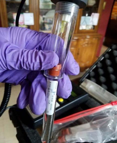
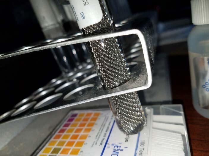
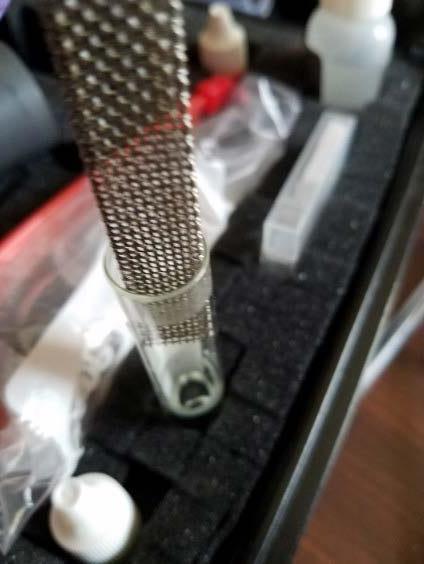
Figure 8: HMB® testing with the stainless-steel mesh coupon. Inserting the coupon into the reaction tube (left). Fifteenminute reaction period (middle). Inserting the HMB® measurement needle through the reaction tube stopper to detect change in oxygen partial pressure in the tube’s headspace (right).
coupons with bacteria and oils from your hands, and
ATP Swab Biofilm Test Protocol for Corrosion Rack Coupons Here are the steps when conducting the ATP swab biofilm test with corrosion rack coupons.
1.
2. Remove the coupon holder/carrier with stainlesssteel coupons from its position in the coupon rack.
Swab the outer surface (closest to the coupon rack pipe wall) of the stainless-steel coupon with an UltraSnap™ ATP Surface Test swab. The coupon area to be swabbed is shown in Figure 9. Because particulates can attach to the screw holding the stainless-steel coupon to the holder, avoid swabbing that area to measure only the biofilm associated with the flat coupon surface associated with a more laminar flow. As the results of these tests are relative, the actual number is less important than trendline data. However, it is important to attempt to minimize differences in the swabbed surface area to obtain comparable results on each test occasion. After the coupon surface is swabbed, insert the swab into the tube and perform the (total) ATP test as per 3. Clean the coupon holders with a brush, alcohol wipes, and/or tissues and rinse with treated city water if available. Place new coupons on the coupon holders, using gloves to prevent contamination of the
the manufacturer’s instructions. Record the results. reinstall.
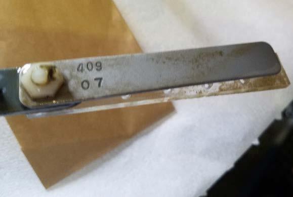
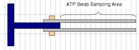
Figure 9: Area of stainless-steel coupon to be swabbed for testing.
ATP and HMB® Testing with MRD Studs Sampling from an MRD for biofilm ATP and HMB® analyses is like sampling for tests conducted on coupons from a coupon rack, but it requires additional steps as described here. The MRD (Figure 10) is fitted with six removal studs that can be used for replicate analyses for the same test, for several different test types, or for biofilms that have developed over more than one exposure period (e.g., one-month and three-month biofilms). Hence, it is important to keep track of the history of each stud. For this reason, the stud holder positions on the MRD are numbered. Again, it is important to wear gloves to minimize contamination of the MRD studs by your hand, and vice versa.
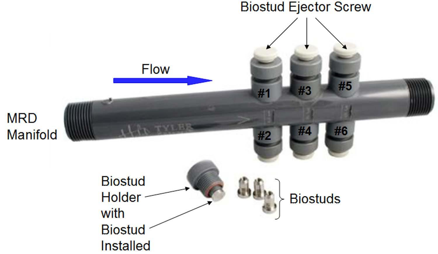
Figure 10: Modified Robbins device.
Here are the steps when testing for biofilm using an MRD stud holder:
1. Remove MRD stud holder from position #1 (top row). Inspect the stud surface for visible fouling.
2. Using an UltraSnap™ Surface ATP pen, swab the flat circular surface of Stud #1 and conduct the ATP analysis. Take care to swab only the flat surface. Significant biomass may accumulate on the stud side/edge, as this part of the stud will be in the gap between the MRD stud holder fitting wall and the stud sidewall. Remove and analyze additional studs as per sampling schedule.
3. Place the MRD stud holder on a clean working surface. The MRD stud holder must be cleaned 4.
5.
6.
7. before a new stud is installed in the holder, and the holder+stud assembly is reinstalled in the manifold. Handle all MRD stud holders in this manner.
Remove the MRD stud holder for Stud #2. Swab the MRD surface with a sterile cotton swab. Cut off and place the swab tip into the HMB® test tube. Alternatively, in systems where no accumulation of biomass occurs on the sides of the stud tip, remove the MRD stud from the stud holder and place the stud in the HMB® test tube. Use the white nylon screw on the holder to push the stud out of the holder. Use forceps or small needle-nose pliers cleaned with an alcohol wipe to grip below the end of the stud for removal. Perform the HMB® analysis. Repeat the HMB® test on other studs as per the sampling schedule.
After ATP and HMB® biofilm sampling/analyses are complete, use the white nylon screws on the MRD stud holders to remove the studs from all tested stud holders. Place used studs in a small container to return to the lab for cleaning. These “biofouled” studs should be considered BIOHAZARD MATERIAL and handled only while wearing disposable gloves until disinfected. Used studs should be cleaned in a mild detergent solution in a sonication bath, or by scrubbing with a nylon bristle brush. Once the studs have been cleaned, they should be rinsed in distilled water, disinfected with alcohol, and allowed to dry in a sterile container until reinstalled in the MRD.
The stud holders, MRD manifold ports, and all O-rings must be inspected and cleaned before reinstallation of new MRD studs. New/clean studs must be handled with gloves during installation to prevent contamination with bacteria and oils from the technologist’s hands.
If the MRD was installed with pipe unions upstream and downstream, and all studs were removed for sampling in this sampling event, remove the MRD and use a bottle brush to clean the main manifold tube. Refit the MRD with the pipe unions.
8. Reinstall the MRD stud holders with new/clean studs in the MRD manifold.
9. Restart flow through the coupon rack and MRD. Check/adjust flow.
Evaluating Biofilm Monitoring Program Data As with all analyses, it is important to understand the factors that contribute to the variability of the microbiology findings used in a biofilm monitoring program. Both variabilities associated with the analysis (i.e., analytical precision) and variability associated with the growth of biofilms must be taken into consideration when evaluating biofilm analysis data. Biofilm growth is not a steady, linear process. Biofilms naturally grow and shed, or “slough,” pieces of biofilm, resulting in greater heterogeneity over area/space and over time than is normally associated with planktonic microbial populations in water samples. Treatment chemicals (biocides, dispersants) applied over the monitoring cycle will promote variability in the size and activity of biofilm populations on samples collected and analyzed at the end of the monitoring period. For these reasons, we have included ATP and HMB® biofilm monitoring data from one testing location as examples of typical data and data variability obtained in a biofilm monitoring program. The planktonic (water sample) dip slide and free/cell ATP data for this location, a facility comfort cooling system using city water as makeup, are also provided (Figure 11). Planktonic microbial populations detected with dipslides were, over the course of the six-month study, consistently in the 102 to 103 colony-forming units per milliliter (CFU/mL) range, except for on the final sample collection/analysis date, when the dipslide result was recorded as Too Numerous to Count (TNTC). ATP analyses of water samples collected during the biofilm monthly biofilm sampling events consistently found mostly cell-associated ATP, with values in the range of 88 to 250 reliable light units (RLU), except for the sample collected on the final sampling date, for which the result was 724 RLU. With this as context, the biofilm ATP and HMB® results for this location are shown in Figures 12 and 13.
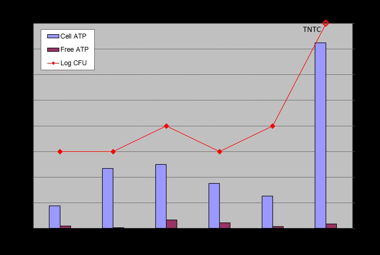
Figure 11: Planktonic microbial population Free ATP and Cell ATP, and dipslide in CFU/mL data for water samples collected during the monthly biofilm sampling events.
Biofilm ATP data (Figure 12) demonstrate good agreement between duplicate MRD studs, with similar month-tomonth trends observed on the stainless-steel coupons. Accepting that some additional error may be associated with the first biofilm sampling and analysis event, it appears that biofilm populations are relatively stable starting with the third sampling event. The high CFU/mL and cell ATP values recorded for water samples collected during sampling Event #6 are not reflected in the ATP data for the one-month biofilm sample retrieved and analyzed on that date. Similarly, significantly elevated biofilm ATP results were obtained for MRD studs and the stainless-steel coupon retrieved during sampling Event #2, whereas planktonic cell ATP and dipslide CFU/mL counts were not elevated for water samples collected and analyzed on this date. The results show particularly good agreement among replicate biofilm samples, but as expected, poor agreement with measures of planktonic bacteria population size/activity. The data suggest that typical one-month biofilm ATP levels at these locations are routinely in the 200 to 400 RLU per sample range, and a trend to ATP results above 400 RLU would be cause for additional investigation.
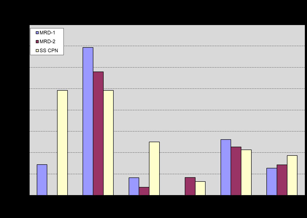
Figure 12: Biofilm ATP results for one-month biofilms on stainless-steel MRD studs exposed in the MRD and stainless-steel strip type corrosion coupon exposed in the corrosion coupon rack.
HMB® analysis results for one-month biofilms on MRD studs, the perforated polycarbonate coupon, and the stainless-steel mesh coupon (Figure 13) are reasonably consistent for samples retrieved and analyzed in each sampling event. The biofilm HMB® data show a pattern, which is like the biofilm ATP data for sampling Events #1 and #3 through #6, with values varying only moderately from month to month. With few exceptions, results generally fall within a 2 to 4 BMR range, suggesting, per the HMB® literature, moderate biofouling. As with the biofilm ATP results, the higher planktonic population dipslide and cell ATP values recorded for sampling Event #6 were not replicated in the HMB® biofilm results for sampling Event #6. In contrast to the elevated biofilm ATP results observed in sampling Event #2, the HMB®/peroxidase activity in all samples for sampling Event #2 was lower than the activity of samples from sampling Events #1 and #3 through #6, reinforcing our understanding that the ATP and HMB® tests are measuring different aspects of microbial activity and can respond differently to system events. The observation that this increase in ATP or decrease in HMB®/peroxidase activity was not observed in subsequent sampling events, suggests this was associated with temporary conditions and/or treatment chemicals in the system during the period preceding sampling Event #2. A sudden significant decrease in biofilm activity levels as indicated by the HMB® data would
normally trigger a review of treatment records and operating system physical/chemical data to determine the cause of the decrease in biofilm activity, and if the change(s) might be leveraged for improved biofilm control in the future.
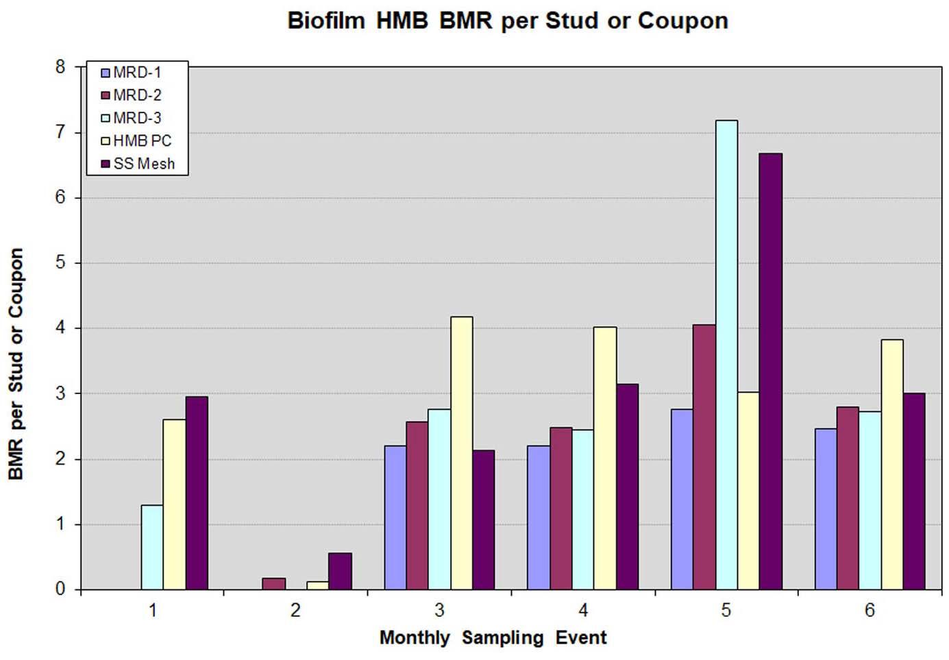
Figure 13: Biofilm HMB® results for one-month biofilms on stainless-steel MRD studs exposed in the Modified Robbins Device, and the HMB® perforated polycarbonate coupon and stainless-steel strip type corrosion coupon exposed in the corrosion coupon rack.
Overall, the ATP and HMB® results for one-month biofilms that collect on MRD studs and a variety of coupon materials demonstrate that reproducibility of biofilm growth on these materials under these conditions and reproducibility of the ATP and HMB® analyses are more than adequate to detect moderate-to-significant changes in biofilms. Once a typical range of ATP and HMB® results is established, trends or sudden changes in the analytical results can be used to alert water technologists to changes in the system requiring their attention. Using Biofilm Monitoring Data Biofilm monitoring information can also provide useful energy demand insights. In Figure 14, we see the correlation between chiller approach temperatures and biofilm formation at our Midwestern industrial plant test site. The approach temperature is the difference between the Freon refrigerant condensing temperature and the temperature of the cooling water exiting the condenser. So, an increasing condenser approach temperature is therefore indicative of a reduction in heat exchange (loss of efficiency), which in turn is caused by some form of fouling. Figure 14 shows good correlation between biofilm formation (as measured by the HMB® detection strategy) and chiller approach temperature in seven of the eight months this was tracked.
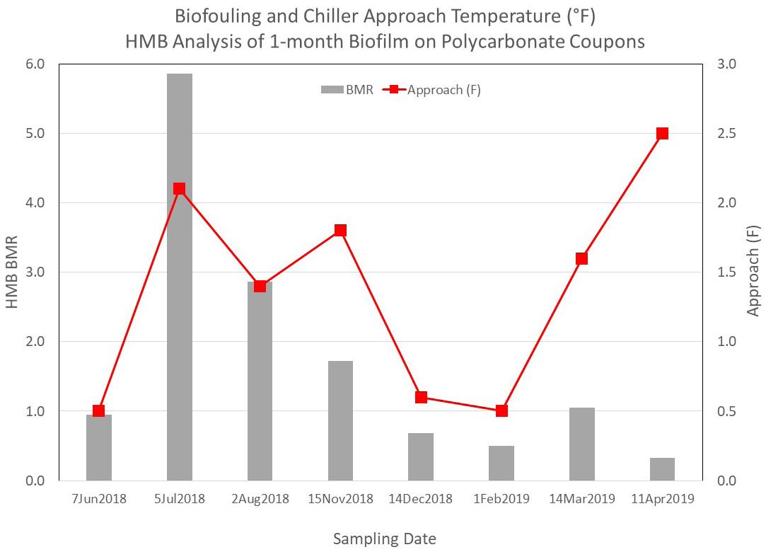
Figure 14: HMB® biofilm monitoring data and chiller approach temperatures at an industrial site.
Conclusions and Recommendations From the field studies carried out and subsequent review of the data generated, several conclusions were drawn that support the use of passive biofilm collection and detection strategies as a field tool for water treatment professionals to implement.
Two of the collection platforms studied were found to be suitable. These methods were practical, consistent, and reproducible. Use of a corrosion coupon rack allows for convenient access to a flowing stream of bulk cooling water. Most/many locations already employ corrosion coupon racks for monitoring metal loss. As shown, modification of those racks can be readily completed to allow for monitoring biofilm.
The MRD is not as convenient to work with but offers the benefits of being able to collect biofilm from different zones of a pipe surface and the collection of multiple data points simultaneously. This method was found to be more expensive and more time consuming.
The stainless-steel corrosion coupon offers a single surface of known dimensions, where one sampling interval yields a single data point. The MRD allows for collection of up to six data points on a specific sampling interval.
Similarly, two of the biofilm detection methods were found to fit the criteria established for the study. They were easy to operate, developed reproducible (digital) data, and functioned in a short amount of time and with relatively low expense.
ATP Detection
HMB® Detection
Each method offered situational benefits, but both were successful in producing a response that can be documented on a service visit, graphed over time and interpreted to allow for either validation of successful control or to provide the operator with insights to alter course in their PM program.
This study offers a ready-to-use approach for adaptation by the water treatment industry. The collection and measurement of biofilm allows for improved water system protection without the cost and complexity of the active techniques, or the online tools on the market.
Once set up and operational, passive biofilm monitoring is expected to add approximately one to 1.5 hours to the service visit. The basic steps involved are:
1. Extract the stainless-steel coupon from the rack for ATP testing, or the polycarbonate (or user supplied stainless steel) coupon for HMB® detection.
2. Swab the entire coupon surface using an ATP pen, or insert the coupon into the supplied test tube for detection by HMB® .
3.
4.
5. Test the ATP level using an ATP Luminometer or the BMR reading using the HMB® method.
Record the value for inclusion into service records.
Clean and replace the stainless-steel or polycarbonate coupon and restart flow.
6. Graph and interpret trend changes over time or at key operational intervals.
Water treaters are encouraged to take advantage of the prescriptive methods outlined. Data gleaned from field detection can be used to confirm program success, adjust biocide dosages, predict system cleaning requirements, stave off a looming problem, or evaluate a new microbial control method being employed.
Acknowledgements The Cooling Water Subcommittee would like to thank AWT for sponsoring and funding this work and the key suppliers whose donations made this work possible (AquaPhoenix Scientific Inc. of Hanover, Pennsylvania, and Hygiena Corp. of Camarillo, California).
Special thanks are also extended to the authors of this article and their employers for their dedicated commitment in seeing this work through to completion. John Caloritis, CWT, holds a B.S. in chemistry and is the technical director of The Metro Group Inc. He has spent 37 years in water treatment in multiple roles, all with one firm. Mr. Caloritis has been active within AWT as both a member and chair of the Cooling Water Subcommittee, a member of the Legionella Task Force, and was recently elected to serve on the AWT board of directors. He can be reached at jcaloritis@ metrogroupinc.com.
Keith Johnson has been in the water treatment industry since 1978 and an independent consultant since 2011. He holds a B.Phil. degree from Miami University and was a graduate student in environmental engineering at the University of Cincinnati. He is a past chair of the AWT’s Cooling Water Subcommittee. He may be contacted at keithmjohn@gmail.com.
Richard Rosser, Ph.D., holds a doctorate in microbiology, and has worked on microbiology issues in industrial environments for 40 years. After 23 years leading oilfield microbiology R&D for Saudi Aramco, Dr. Rosser returned to the United States, and for the past 12 years he has worked with AMSA, Inc. on microbial biofilm control. He can be contacted at rrosser@ amsainc.com.
Derrick Vandenberg, CWT, holds a B.Sc. in chemistry and is the Edmonton District Manager of Guardian Chemicals Inc. He has 18 years’ experience in water treatment and thoroughly enjoys his career. Mr. Vandenberg is active within the AWT as a Cooling Water Subcommittee member, and recently accepted the role of chairperson. He may be reached at dvandenberg@ guardianchem.ca.
Introduction to Pharmaceutical Waters for U.S. Products
T.C. Soli, Ph.D., Soli Pharma Solutions, Inc.
Background Water is prolifically used in the pharmaceutical industry. Its applications range from preparing compendial grades of water to manufacturing active ingredients, excipients, and a wide variety of sterile and nonsterile finished products (including packaged sterile waters), as well as for testing of all those materials and for equipment and facility cleaning. This article will examine treatment methods, pharmaceutical water types, and uses.
The various pharmaceutical water grades in the United States begin with the minimum quality of drinking water (as specified in Drinking Water regulations for the United States, Europe, Japan, and the World Health Organization [WHO]) (Note, a water user must choose one of these areas for regulatory compliance). Pharmaceutical water is used for initial equipment cleaning as well as for manufacturing pharmaceutical ingredients unless a purer form of water is needed to meet product specifications. For equipment cleaning, the water quality used for the finished raw material or product must be the final equipment rinse unless a solvent is used. Bulkproduced United States Pharmacopeia (USP) Purified Water (PW) is used to make U.S.-marketed nonsterile products and some noninjectable sterile products. Bulkproduced USP Water for Injection (WFI) is used for making U.S.-marketed injectable products.
Most USP test methods require the minimum water quality to be USP PW, but other nonmonographed waters, often identified by a quality attribute or a method of production in its name, are specified for some analyses, often very dated. Sterile packaged versions of bulk PW and bulk WFI are not as pure as their bulk counterparts, primarily because of packaging leachables. USP plans to update the TOC specifications for sterile packaged waters (published in USP 2021 Issue 1, effective May 2021) to better control the level and safety of these packaging leachables.
Where Water Is Used in Pharmaceutical Manufacturing With few exceptions, by quantity, water is the most heavily used article in pharmaceutical manufacturing. It can be used as a cleaning agent; a reagent in laboratory tests; a manufacturing aid or solvent in the fermentation, synthesis, or purification of a pharmaceutical active or excipient ingredient; and an ingredient in a pharmaceutical product, and it can itself be a packaged
pharmaceutical product. Needless to say, with all these possible uses, the necessary minimum purity of this water could be quite varied if not specifically required by the regional regulators and pharmacopoeia where the associated finished product will be marketed.
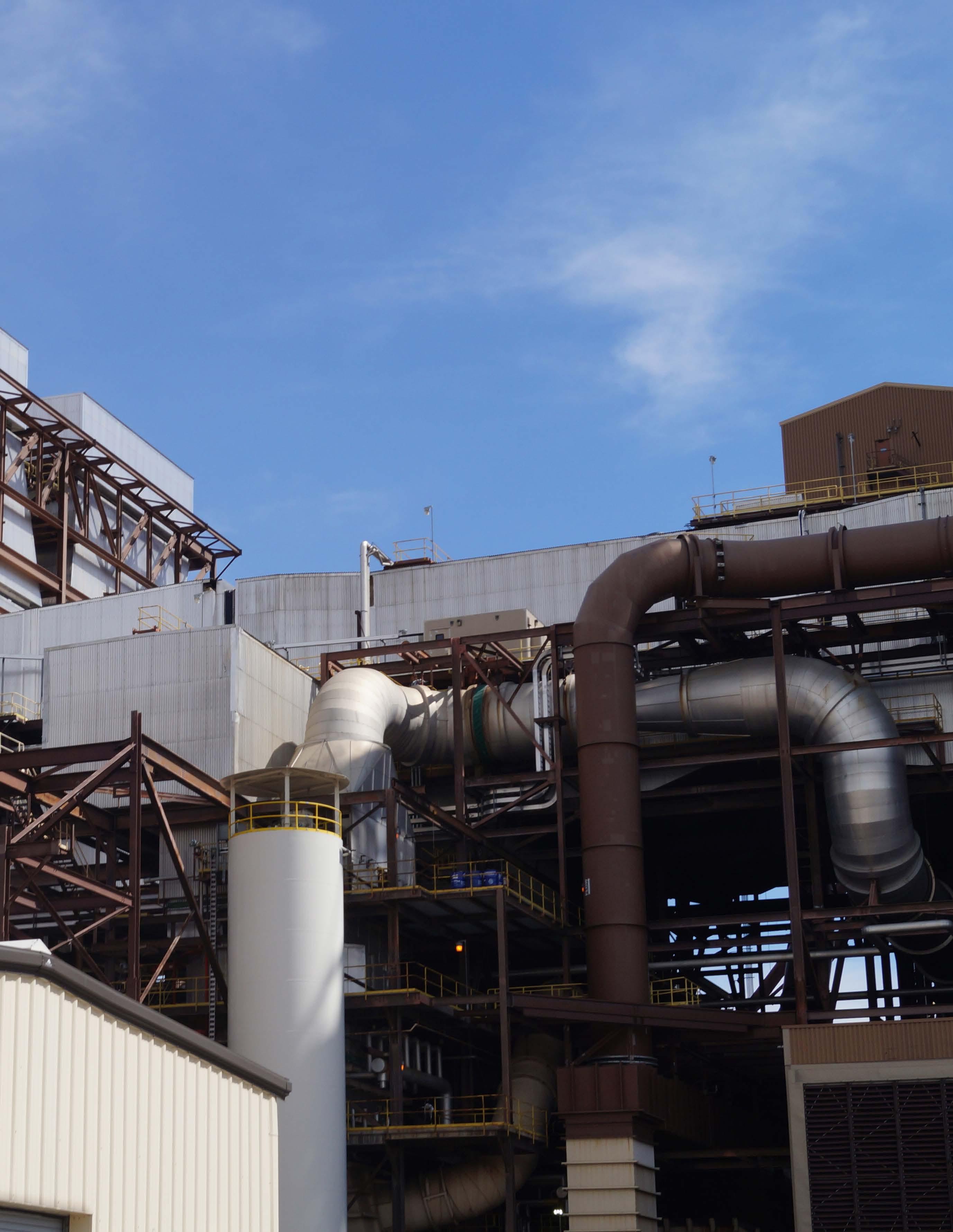
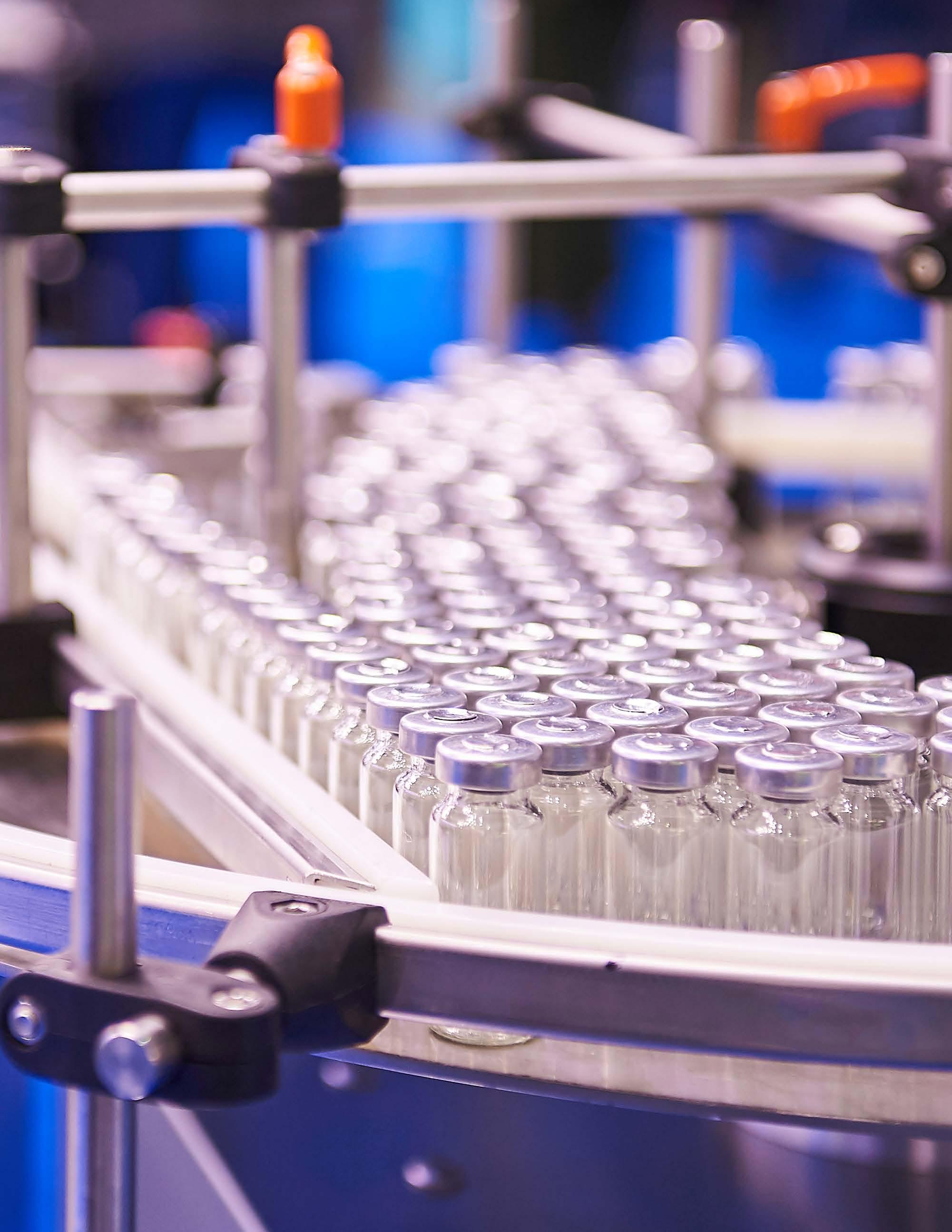
In this article, we will examine waters for products marketed in the United States, regulated by the U.S. Food and Drug Administration, and whose specifications are based on the USP, even when the product is manufactured in another country and sold in the United States. Where products are manufactured in the United States and marketed, for example, in Europe, compliance with the pharmacopoeia and regulatory expectations of the marketed country is required, unless the USP water quality exceeds that of the market country (e.g., USP PW exceeds the purity of the European Pharmacopoeia [EP] Purified Water). Please note that this article is an introduction to pharmaceutical water uses and treatment and it does not include specific discussion about treatment technologies used by the industry. However, to provide better context, Figures 1 through 4 show examples of pharmaceutical products in which water is an ingredient and treatment technologies used at facilities to make pharmaceutical-grade waters.
Making Purer Water From Drinking Water Where water purities better than drinking water are required in pharmaceutical manufacturing, it is most usual for the manufacturing facility to have a validated onsite water purification process that consistently and reliably removes impurities from the starting water, which must minimally be Drinking Water quality. According to USP, the quality of that Drinking Water must comply with all the specifications for one of the four allowed sets of drinking water regulations:
1.
2. The U.S. EPA National Primary Drinking Water Regulations (NPDWR)
The Drinking Water regulations of the European Union
3.
4. The Drinking Water regulations of Japan
The WHO Guidelines for Drinking Water
Even though the latter guidelines are not considered to be mandatory by the WHO, if you are using this drinking water for any purpose in a pharmaceutical facility that manufactures product for sale in the United States, as will be discussed later, compliance with all the specifications within this guideline is not optional— they are mandatory. The same complete compliance rule is true of the other three; compliance with all the specifications within the chosen set of Drinking Water regulation options is mandatory. Refer to Table A for a comparison of the U.S. and WHO Drinking Water attribute specifications.
The reason for only certain specified Drinking Waters being suitable is toxicological safety. The attributes in these four sets of Drinking Water regulations are vetted to be safe, nontoxic levels of water impurities. So, if the starting water is safe to drink because all potentially toxic inorganic and organic impurities are well below a level of concern, then none of those specific impurities need to be retested in the finished water, allowing the nonspecific tests of conductivity and total organic carbon (TOC) to be suitable quality tests for chemical purity and safety.
Making Active Pharmaceutical Ingredients As varied as the kinds of active pharmaceutical ingredients (APIs) are, so are the purities of the water needed for the various stages in the synthesis or preparation of those APIs. It is globally recognized through ICH Q7A that the minimum water quality for these processes must be drinking water. According to that harmonization document, that means it meets the WHO Guidelines for Drinking Water. According to the FDA and USP, the water must comply with the specifications of any of the four drinking water options mentioned above.
Of course, if even purer water is needed to achieve the desired purity of the API or intermediate, a purer water must be used—as defined by the user. For processing equipment cleaning, the initial cleaning can be done with drinking water, but the final rinse, if it is with water, must be whatever purity of water is used in that equipment’s material processing. The water does not have to comply with a specific compendial water grade unless the user specifies that it does. However, whatever water purification process is used to produce this water, that process must be validated to be consistent and reliable, just like any water purification system and every manufacturing process in a pharmaceutical setting.
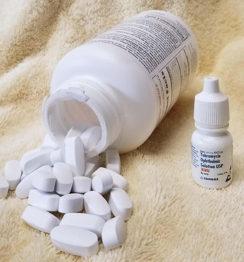
Figure 1: Two examples of pharmaceutical products that require pharma-grade water at some point in their production process—eye drops and tablets.
Making Non-Sterile Drug Products If the product being made is a non-sterile drug, like a tablet, capsule, oral liquid, skin cream, suppository, or similar product, and water is used in the formulation, even if it is no longer present in the final product (such as with tablets and capsules), that water must be USP PW if the product is marketed in the United States. See Table B comparing the attributes of USP’s various monographed waters.
Since water is often used for cleaning the equipment used to compound, manufacture, and package these products, the initial equipment cleaning may be accomplished with Drinking Water, but the final rinse must be the same water used in the product’s formulation—in this case, PW.
Making Sterile Drug Products Because of the extremely sensitive or infection-prone nature of the location where a particular product is applied or introduced, the product may need to be sterile. It could be injected into sterile tissue or applied to abraded or compromised skin or mucous membranes or to other nonsterile tissues that are otherwise highly susceptible to infection. The quality of the water used for these sterile products, which are either sterilized in their packaging after they are manufactured or formulated with sterile materials and packaged in an aseptic manner that avoids contamination, depends on whether they are used externally on nonsterile tissue or injected into sterile tissue.
Making Injectable Sterile Drug Products When a drug product is injected through the skin and into the body (a parenteral injection), such as into or just under the skin, into muscle tissue, into a sterile cavity, or into the blood stream, contaminating bacteria that could have been present in the formulation but killed by the product sterilization process could still release a bacterial cell component that is quite toxic to the human body. This toxic cell component is a structural macromolecule in the cell walls of some bacteria, particularly the bacteria that can grow as difficult-to-control biofilms in pure water systems as well as some products. After those bacteria have been killed in the process of sanitizing a water system or sterilizing a product, this toxic cellular component is released from the dead bacterial cell. It goes by various names, such as endotoxin (because it is a toxin found within
and usually bound to living bacterial cells), pyrogen (because one of the most noticeable pharmacological effects of the molecule is the generation of a fever), lipopolysaccharide (because this large, complex molecule contains both lipid and polysaccharide components), or LPS (for short).
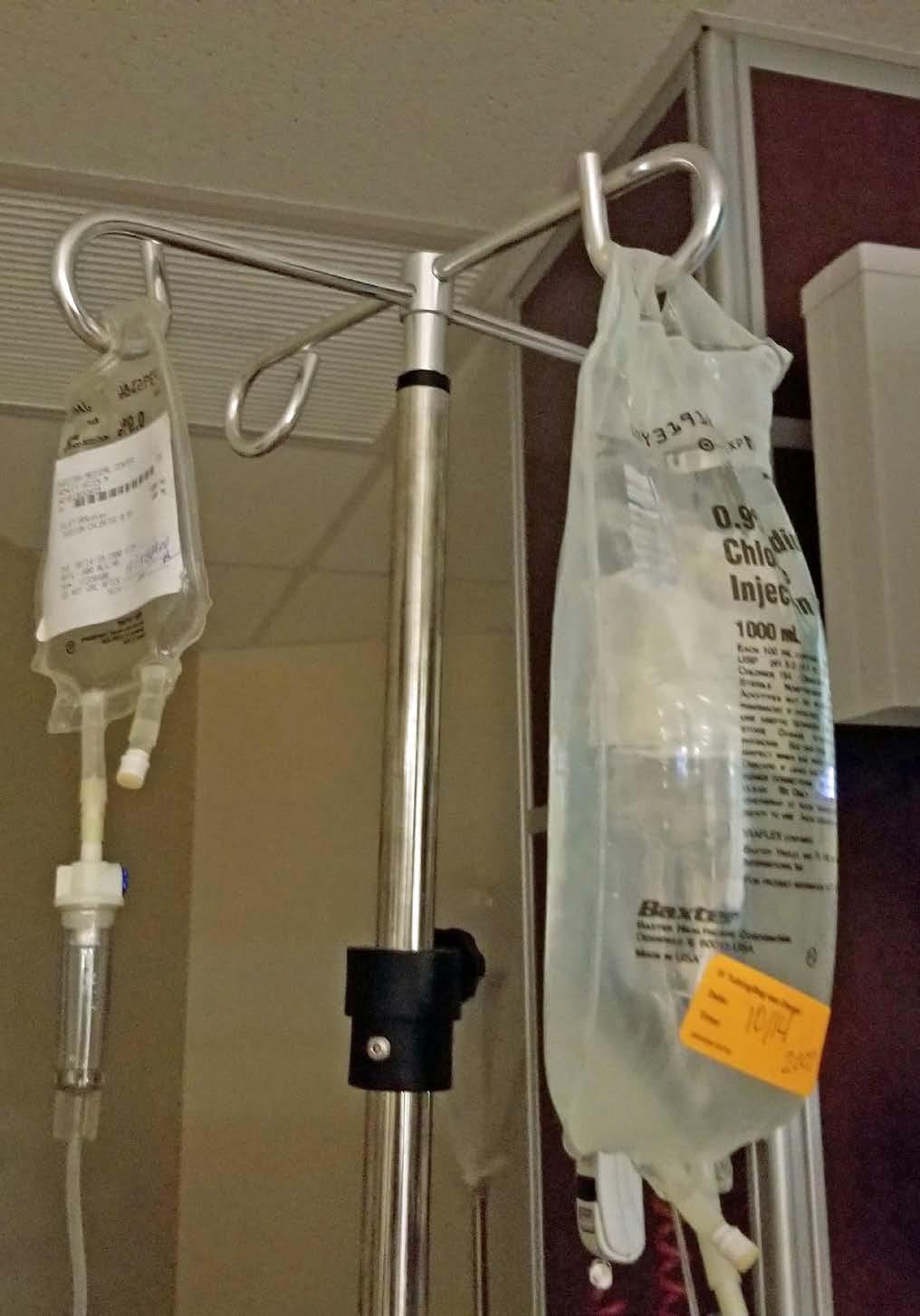
Figure 2: WFI is the primary ingredient in IV liquids frequently administered in hospitals and other medical facilities.
Therefore, the water used as an ingredient for these injectable formulations must be USP WFI, which has an endotoxin specification that renders it safe for most parenteral applications. To meet that specification, the WFI system producing this water needs to be as free from these bacteria and these already-freed endotoxin components as possible, in addition to being otherwise chemically pure enough for these sensitive uses. By contrast, USP PW, which is not used for injectable products, has no endotoxin specification but is otherwise equally chemically pure (see Table B).
Just like with nonsterile products, the water used for initial cleaning of equipment used in their manufacturing may be accomplished with Drinking Water, but some firms choose for this initial cleaning to use purer water (e.g., PW, hot WFI) that contains fewer chemicals and microbial-related contaminants. Injectable products are generally aqueous and relatively easy to clean, so even though the WFI is more expensive to make than PW, and certainly more costly than drinking water, the mostly aqueous products usually render manufacturing equipment very cleanable, so relatively little water is needed to achieve a clean condition. However, the final equipment rinse must always be of the same water quality used in the product’s formulation—in this case, USP WFI. To avoid needing to do costly and time-consuming depyrogenation of large bulky equipment, it can be kept relatively apyrogenic or pyrogen-free by simply doing all cleaning with WFI and never introducing the possibility of endotoxin or microbial contamination from contact with less pure waters.
Making Noninjectable Sterile Drug Products There are a few pharmaceutical products that still need to be sterile because of the infection-prone locations where they are used. Examples are ophthalmic products, first aid products applied to abraded or inflamed skin, some optic treatment products, and inhaled liquid products for some debilitating lung diseases. But because these drugs are not injected, there are far fewer concerns regarding endotoxin in the product or water used to formulate these products. The skin and mucous membranes are resistant to the penetration of endotoxin molecules that could be in the ingredient water. Therefore, USP PW (which has no endotoxin specification) is generally adequate for formulating these products. The same waters for cleaning as used for nonsterile drug products can be considered, with the same caveat of using the same water quality as in the formulation for the final equipment cleaning rinse.
Performing Laboratory Analyses USP requires that USP PW is the minimum quality of water that must be used in all analyses in the USP compendium, unless otherwise specified. Of course, there could be needs for water of greater purity for some trace level or otherwise sensitive analyses, compendial or not, and also for analyses performed in the laboratory from other organizations, such as ASTM (American Society for Testing and Materials International), ISO (International Standards Organization), and CLSI (Cli nical and Laboratory Standards Institute). Just as with manufacturing equipment cleaning, less pure water, such as drinking water, could be used for initial cleaning of labware, but the final rinse must be at least PW quality.
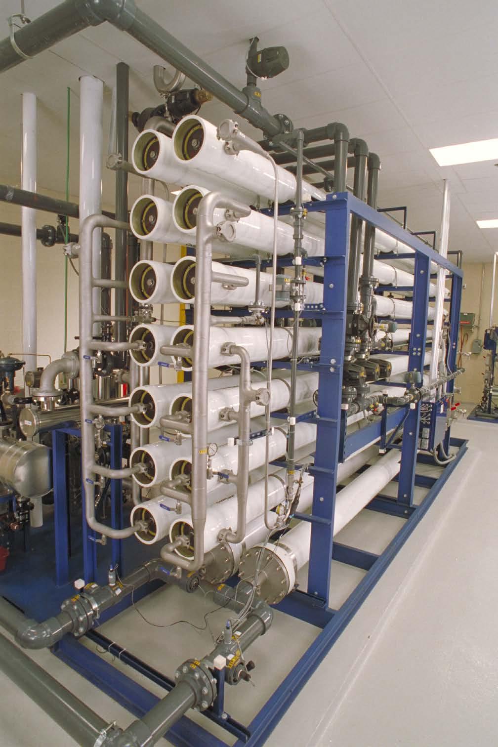
Figure 3: Reverse osmosis is an important treatment technology used in the production of pharmaceuticalgrade waters.
“Water” Means PW In USP’s General Notices section, it in essence states that where the term “water” is used in the text of analytical chapters or monographs, USP PW is the “water” that must be used, unless otherwise specified.
Test-Specific Waters Several tests within USP are quite dated, often being incorporated using the language of the innovator who submitted their test wording to the compendium for
these ancient but still used products. The innovator’s name of the water could pre-date the switch to conductivity and TOC in the Purified Water and Water for Injection monographs (occurring in 1996) because, frankly, the original wet chemistry tests specified prior to that time for these monographs did little to delineate the water’s purity.
Often the terms used either vaguely described an attribute or a preparation process with little other detail. Sometimes, when the test was intended to detect trace levels of analyte “X”, the specified water would be “X-free water”. One can never be certain that there is absolutely zero “X” in the water because no analysis can detect the absolute and complete absence of any analyte, “X” or otherwise. There is always a limit of analytical detection for any analyte. So, the implication is that there is not enough “X” in the water to be detectable by or interfere with the test where it is specified.
The author considers these waters to be “mongrel waters” since they are usually very poorly defined, compared to the monographed waters. Some of these waters at least have specifically defined preparation methods or rudimentarily defined attributes within the Reagents section of USP, such as:
“Carbon Dioxide-Free Water”: PW that is either vigorously boiled for at least 5 minutes and cooled while protected from absorption of atmospheric carbon dioxide or PW with a resistivity of not less than 18 megohm centimeter (Mohm-cm).
“Deaerated Water”: PW that is treated to reduce the content of dissolved air by either vigorously boiling for 5 minutes and cooling, treated with ultrasonic vibrations, or other suitable means. “Particle-Free Water”: PW that has been passed through a 0.22-micron (µm)-rated filter membrane.
“Organic-Free Water”: PW that produces no significantly interfering peaks when chromatographed according to the Residual Solvents test in Chapter <467> of the UPS.
Some mongrel waters are merely synonyms of others, such as: “Degassed Water”, which is presumably equivalent to “Deaerated Water”; “Nitrogen-Sparged Water”, presumably equivalent to “Carbon Dioxide-Free Water”; and “Filtered Water”, presumably equivalent to “ParticleFree Water”.
Other mongrel waters within the pages of USP are much less defined, include waters whose names describe how they are prepared. So, even without specific purity specifications, knowledge of the attributes bestowed by the purification process implies their purity to a degree, such as: “Distilled Water”, “Deionized Water”, “Double Distilled Water”, “Deionized Distilled Water”, “Freshly Distilled Water”, and “Degassed Filtered Water”, among others.
And still there are other pharmaceutical waters that are identified by the type of use they may have, such as: “Cell Culture Water”, “Bacterial Endotoxins Test Water”, and “HPLC Grade Water”.
The irony of many of these mongrel waters is that the purity implied by their names or even their preparation methods may not be important for their specified analytical uses. They may just be traditional. The most common offender is “Carbon Dioxide-Free Water”, which is by far the most specified non-monographed mongrel water. When pure water contains dissolved CO2, it is acidic
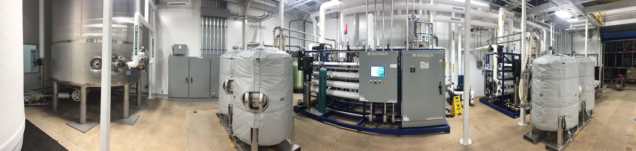
Figure 4: A panoramic view of storage tanks and a water treatment system in a pharmaceutical plant.
near pH 6 or the high 5’s, and it contains bicarbonate ions from the dissolved and dissociated CO2, causing its equilibrium with carbonates and bicarbonates. But when it is truly CO2-free, it has a nearly neutral pH and very few bicarbonate ions. You would think that this water’s analytical uses would center around pH-sensitive analyses, acidity/alkalinity tests, or tests for carbonates, but it is specified in a wide variety of tests that are not impacted by its acidic pH, the presence of bicarbonate ions, or its minimal buffering capacity.
As it turns out, the preparation of Carbon DioxideFree Water is more of a chemistry lab tradition than it is an analytical necessity. Many older classically trained chemists have, in an abundance of precaution from training in schooling, always just used boiled and cooled water (supposedly making it carbon dioxide-free as well as temporarily degassing it) for preparing all reagents and performing traditional wet chemistry tests. It is an unnecessary tradition that continues to this day in many USP tests where this mongrel water is specified for use.
What these analysts may not realize is that carbon dioxide re-absorption by the water is almost immediate (though it does take some time to reach equilibrium) and difficult to completely avoid. Fortunately, it has negligible impact on the test results, even for pH-sensitive tests, but unfortunately, it creates unnecessary work for the lab analysts. In most cases, plain old ordinary PW, which has not been boiled and cooled and therefore contains some level of dissolved CO2, works just as well. But you must use the water specified for a procedure, right? Even if it makes no sense, right? It is time for USP to change its procedures to what makes scientifically defensible sense.
As a Pharmaceutical Product There are a number of monographs within USP for packaged and sterilized waters that are made from bulk-produced PW and WFI, each with its own packaging styles, limitations, intended applications, and chemical purity specifications: Sterile Purified Water, Sterile Water for Injection, Sterile Water for Irrigation, and Sterile Water for Inhalation are four of them (see Table B). All these packaged sterile waters originated as monographs long before the advent of conductivity and TOC being specified in the bulk water monographs for PW and WFI. So, the original qualitative wet chemistry tests of yesteryear, some dating back to about 1900, were present until 2009 and replaced with a packaging size-based conductivity test. However, because of resistance from the manufacturers of these waters to an equally contemporary organic specification using TOC, the century-plus old test for organics, the Oxidizable Substances test, was retained as an alternative to the TOC test with a specification of 8 ppm. That archaic test option was always intended to sunset, leaving only TOC as a specification to control the organic content in those sterile packaged waters to a “safe’ level, whatever that level was.
As had evolved in the absence of a meaningful organic test, the contemporary plastic packages with desirable moldability, strength, shape conformance, and flexibility were developed. But these packages were very bad about leaching organic compounds and plasticizers from their inner surfaces into the water without the manufacturer’s knowledge because they still passed the archaic Oxidizable Substances test that could not detect these complex organic compounds.
So, in the absence of awareness of their presence by test, the TOC content of the more contemporary sterile packaged waters skyrocketed to levels many-fold higher than the bulk water filled into these packages, in some cases, as high as 100 parts per million (ppm). By contrast, the water put into these packages from a WFI system has a TOC specification of 0.50 ppm, but most firms produce WFI that is about 1/10th to 1/100th that level. And, even Drinking Water has TOC limits in the 2-ppm area. Something seemed intuitively wrong about such high TOCs in the sometimes-large doses of water going into your body intravenously from those contemporary packages!
So, USP is in the process of applying the contemporary and quantitatively meaningful product tests of conductivity and TOC to the sterile packaged pharmaceutical water industry that is accustomed to having few limitations on packaging organic leachables. Are high levels of these organics safe? All historical packaging safety tests that assess acute toxicity as well as the millions of supposedly uneventful users to date say they are. But evidence is emerging that certain of these leaching compounds may not be so safe to some populations (e.g., neonates and pregnant women) when chronically administered in large
volumes, particularly from the leachable phthalate plasticizers that make some plastic packaging very flexible.
The USP will institute new TOC specifications and delete the Oxidizable Substances test option for these packaged sterile waters in May of 2021. These changes should better assure the safety of sterile packaged waters at what USP feels is a scientifically defensible and achievable level. These new TOC specifications are complexly worded with a set of limits that vary as a function of package size since the packaging surface-area-to-volume ratio varies so dramatically with the variety of packaging sizes now available (from pre-filled syringes of possibly less than 1 cubic centimeter (cc) to 2 liter (L) or larger bags and bottles). That TOC specification now contains wording that forces the vendor of these packaged sterile waters to assess the identity and safety of each organic species in the water if the total TOC level is higher than a threshold value. These various specifications for the various monographed USP waters are found in Table B.
To be certain, the chemical purities of the bulk PW and bulk WFI are far and away better than the chemical purity of the sterilized packaged forms of those waters. Those sterile water monographs state that aside from the sterility attribute, the bulk and sterile packaged forms of PW and WFI could be used interchangeably. However, in USP Chapter <1231>, that interchangeability statement is qualified by explaining the chemical purity differences between the non-sterile bulk and sterile packaged waters means that there could be performance differences between the bulk and packaged versions of the same type of water and that the user must assure the suitability for the intended use of the water they choose to use.
Microbiological Specifications for Compendial Waters Little controversy exists over the required microbial attributes of the sterile packaged waters— they must be sterile, assured by a validated terminal sterilization (usually by steam autoclave) of the final packaged product, and checked by sterility test.
However, a large controversy exists over the microbial content of the non-sterile bulk PW and WFI from which the sterile waters are made as well as the test method to assess it. The monographs for PW and WFI intentionally contain no mention of a microbial attribute. This seemingly unfathomable oversight is explained in USP’s informational Chapter <1231> Water for Pharmaceutical Purposes (see USP-National Formulary [NF] 2020) as being because there are some uses of these waters where the microbial content is irrelevant, such as most laboratory applications and some cleaning applications, making any mandatory microbial testing requirement an inappropriate burden for those uses.
However, that means that there is no mandatory compendial specification and no specified test method in the PW and WFI monographs. But that does not mean that microbial content of these waters is unimportant for many of its applications. To the contrary, it is very impactful for manufacturing uses and in some system design and maintenance scenarios, difficult to control and difficult to properly sample so that sampling technique does not bias the test result.
The regulator’s expectation for the upper limit of microbial content is 100 Colony Forming Units per milliliter (CFU/mL) for PW and 10 CFU/100 mL for WFI. This “expectation” should be interpreted as a true specification since an OOS (Out of Specification) investigation is the required action of exceeding these values so that the cause of the high microbial count can be determined, mitigated, and prevented from recurring and its impact on finished product where the water has been used can be assessed.
The problem with high microbial counts in water samples is that often it is a poorly executed sampling procedure that causes what appears to be high microbial counts for what might otherwise be pristine water produced and delivered by the water system. This sampling issue is beyond the scope of this article but is discussed in detail in USP’s Chapter <1231>. The other issue, as mentioned above, is what test method (sample volume, growth medium, incubation temperature and duration) should be used to assess the microbial count in the water. As
with the specification issue, this microbial testing issue is also beyond the scope of this article and discussed in detail in <1231>.
Conclusions What are the “take home” messages from this article?
Water is a prolifically used article in the pharmaceutical industry, for everything from the preparation of compendial grades of water, to manufacturing active ingredients, excipients, and a wide variety of sterile and non-sterile finished products (including several packaged sterile finished products itself), to testing of all those materials, to cleaning of the manufacturing and testing equipment as well as the facility.
Specific Drinking Water grades are required as the starting water for making purer compendial water grades that are intended for making specific classes of products, depending on the sensitivity of where the product is used on or in the body.
Pharmaceutical water grades could be as pure as
WFI to as “impure” as Drinking Water (but only specific regional grades). Water complying with the four specified Drinking Waters do not have identical attributes or specifications but are all equivalently safe to consume.
In USP, there is intentionally no microbial specification or test specified in the PW and WFI monographs, but it is nevertheless important for many uses to know and control the microbial content of these waters. The non-mandatory informational
Chapter <1231> contains a wealth of information regarding grades of pharmaceutical water, water system microbial control, validation, sampling, and test method choices. In USP laboratory analyses, the minimum water purity needed is PW, unless otherwise specified. Test-specific purity requirements could be needed for some analyses, but they are usually not monographed and sometimes have poorly defined purities.
Sterile packaged forms of PW and WFI, though stated in USP monographs to be equivalently applicable to their respective bulk waters in usage, are not as pure as the bulk waters from which they are made due to packaging leachables, so be careful of the water chosen for a given application.
“T.C.” Soli is a Ph.D. microbiologist and president of Soli Pharma Solutions, Inc. and for the past 16 years has offered troubleshooting consulting and training services covering water systems, sterilization, sterile and non-sterile manufacturing, microbiological laboratories, and microbial and beta-lactam contamination control. Dr. Soli has a combined 42 years of pharmaceutical experience as a consultant and with operating companies, including DSM Pharmaceuticals, Catalytica Pharmaceuticals, Glaxo Welcome, Burroughs Wellcome, and Pfizer. For the past 20 years, he has served as a member of USP Expert Committees responsible for everything related to high-purity water in USP/NF. He continues to serve USP with his water expertise in the role of Expert Advisor. Before that, Dr. Soli previously served for 18 years on the PhRMA Water Quality Committee, whose achievements included creating the Water Conductivity and TOC specifications used in USP Purified Water and Water for Injection since 1996 (USP 23, Supplement 5). Dr. Soli may be contacted at tcsoli@earthlink.net.
Table A: Comparison of U.S. (NPDWR) and WHO Drinking Water Specifications
US: 40 CFR 141 (2015) WHO: Guidelines for Drinking Water 4th Ed (2011)
Attribute (as mg/L unless otherwise noted)
Inorganic Chemical Contaminants: Antimony Arsenic Asbestos (as MFL [million fibers per L] > 10um long) Barium Beryllium Boron
U.S.
0.006 0.01 7 2 0.004
WHO
0.02 0.01
0.7
Attribute (as mg/L unless otherwise noted)
Cadmium Chromium (total) Copper Cyanide (as free Cyanide) Fluoride Lead Manganese Inorganic Mercury Molybdenum Nickel
Nitrate (US as N, WHO as NO3 -) Nitrite (US as N, WHO as NO2 -) Total Nitrate and Nitrite (as N) Selenium Thallium
Uranium
Organic Chemical Contaminants: Acrylamide (when used as flocculant at 1mg/L) Alachlor Aldicarb Aldicarb sulfoxide Aldicarb sulfone Aldicarb (sulfoxide and sulfone) Aldrin and Dieldrin (combined) Atrazine (plus chloro-s-triazine metabolites for WHO) Benzene Benzo[α]pyrene (PAHs) Carbofuran Carbon tetrachloride Chlordane Chlorobenzene Chlorotoluron Chlorpyrifos Cyanazine Dalapon 1,2-Dibromo-3-chloropropane (DBCP) 1,2-Dibromoethane (Ethylene dibromide) o-Dichlorobenzene p-Dichlorobenzene 1,2-Dichloroethane (Ethylene dichloride) 1,2-Dichloroethene (Acetylene dichloride) 1,1-Dichloroethylene cis-1,2-Dichloroethylene trans-1,2-Dichloroethylene Dichloromethane (Methylene chloride) 2,4-D (2,4-Dichlorophenoxy acetic acid) 2,4-DB (4-(2,4-Dichlorophenoxy) butanoic acid) DDT and metabolites Dichloroprop 1,2-Dichloropropane 1,3-Dichloropropene Di(2-ethylhexyl)adipate Di(2-ethylhexyl)phthalate Dimethoate
U.S.
0.005 0.1 1.3 Action Level 0.2 4.0 0.015 Action Level
0.002
10 1 10 0.05 0.002
0.0005 0.002 0.003 0.004 0.002
0.003 0.005 0.0002 0.04 0.005 0.002 0.1
0.2 0.0002
0.6 0.075 0.005
0.007 0.07 0.1 0.005 0.07
0.005
0.4 0.006
WHO
0.003 0.05 2
1.5 0.01 0.4 0.006 0.07 0.07 50 (short-term) 3 (short-term)
0.04
0.03
0.0005 0.02
0.01 0.00003 0.1 0.01 0.0007 0.007 0.004 0.0002
0.03 0.03 0.0006
0.001 0.0004 1 0.3 0.03 0.05
0.02 0.03 0.09 0.001 0.1 0.04 0.02
0.008 0.006
Attribute (as mg/L unless otherwise noted)
Dinoseb 1,4-Dioxane Dioxin (2,3,7,8-TCDD) 1,2-Diphenylhydrazine Diquat Edetic acid (EDTA free acid) Endothall Endrin Epichlorohydrin (used as a flocculant at 20mg/L) Ethylbenzene Ethylene dibromide (EDB) Glyphosate Heptachlor Heptachlor epoxide Hexachlorobenzene Hexachlorobutadiene Hexachlorocyclopentadiene (HEX) Hydroxyatrazine (Atrazine metabolite) Isoproturon Lindane MCPA ((4-Chloro-2-methylphenoxy) acetic acid) Mecoprop Methoxychlor Metolachlor Microcystin-LR (free + cell bound) Molinate Nitrilotriacetic acid (NTA) Oxamyl (Vydate) Pendimethalin Pentachlorophenol Picloram Polychlorinated biphenyls (PCBs) Simazine Styrene (Ethenylbenzene) Terbuthylazine Tetrachloroethylene (PCE) Toluene Toxaphene 1,2,4-Trichlorobenzene 1,1,1-Trichloroethane 1,1,2-Trichloroethane Trichloroethylene (Trichloroethene, TCE) 2,4,6-Trichlorophenol (a DBP) 2,4,5-Trichlorophenoxyacetic Acid (2,4,5-T, Trioxone) 2-(2,4,5-Trichlorophenoxy)propionic acid (2,4,5-TP, Fenoprop, Silvex) Trifluralin (Trifluron/Triflumuron) Vinyl chloride (Chloroethylene) Xylenes (total)
Disinfection Byproducts (DBPs): Total Trihalomethanes (sum of four THMs as rolling quarterly avg) Haloacetic acids (sum of five HAAs as rolling quarterly average) Bromate Chlorate Chlorite
U.S.
0.007
3.0 x 10⁻⁸
0.02
0.1 0.002
0.7 0.00005 0.7 0.0004 0.0002 0.001
0.05
0.0002
0.04
0.2
0.001 0.5 0.0005 0.004 0.1
0.005 1 0.003 0.07 0.2 0.005 0.005
0.05
0.002 10
0.080 0.060 0.010
WHO
0.05
0.6
0.0006 0.0004 0.3
0.0006
0.2 0.009 0.002 0.002 0.01 0.02 0.01 0.001 0.006 0.2
0.02 0.009
0.002 0.02 0.007 0.04 0.7
0.02 0.2 0.009 0.009 0.02 0.0003 0.5
≤1
0.01 0.7 0.7
Attribute (as mg/L unless otherwise noted)
Chloroform (Trichloromethane, a THM) Bromodichloromethane (a THM) Dibromochloromethane (a THM) Bromoform (Tribromomethane, a THM) Dichloroacetic acid (a HAA) Trichloroacetic acid (a HAA) Monochloroacetic acid (a HAA) Dibromoacetonitrile Dichloroacetonitrile N-Nitrosodimethylamine
Radioactive Contaminants: Adjusted Gross alpha activity (as pCi/L, excl. Radon and Uranium) Radium226 + Radium228 activity (as pCi/L) Uranium (as mcg/L) Total Beta and Gamma Emitters (as mrem/yr (in 730L or 2L daily)) Gross alpha particle activity (as Bq/L, excl. Radon) Gross beta particle activity (as Bq/L)
Microbiological Contaminants: Heterotrophic Plate Count or HPC as CFU/mL Total Coliforms/100mL (% positives per month if >40 sites) Total Coliforms/100mL (# positives per month if < 40 sites) Fecal Coliforms and E. coli /100mL Turbidity (per month as NTUs in daily samples):
Miscellaneous Attributes: Total Organic Carbon (TOC, Rolling quarterly avg) Disinfectant Residual:
Chlorine (as Cl2, US minimum 0.2) Chloramines (as Cl2, US minimum 0.2) Monochloramine
Chlorine dioxide
Sodium Dichloroisocyanurate
U.S.
15 5 30 4
500 Action Level 5 1 0 0.3 (<95%), <1.0 (100%)
2.0
4.0 4.0
0.8
WHO
0.3 0.06 0.1 0.1 0.05 0.2 0.02 0.07 0.02 0.0001
0.5 1
0
5
3
50 (40 cyanuric acid)