AFTERGLOW Adonijah Campbell Richard Desjardins Ashton Schlundt
Wentworth Institute of Technology Department of Architecture Fabrication Methods Arch9700 Spring 2019
Abstract |
The “Afterglow” Project develops a method of making light drawing more precise through the use parametrically programmed design paths. Traditional methods of light drawing rely on the movement of sparklers or flashlights. They produce active images which show the passage of time within the resulting long exposed photograph. This method however, leaves room for unseen imperfections due to no live time results along with a lack of replicability.
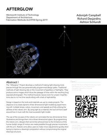
Figure 1 Simple Path Axon of Robot Producing a Light Path Based on it’s Live Time Sound (Campbell, Desjardins, Schlundt, CC BY-NC-SA).
Design is based on the tools and materials we use to create projects. The objective is to create dynamic three dimensional light models by experimenting with multiple lamps, colors, movement, and speeds and fully utilizing the abilities of the robotic arm. By using light as a material, the tool will form itself around how it must craft the most successful light model. The use of the six-axes of the robotic arm animates the two dimensional rhino illustrations and brings them into a three dimensional space. By programming the robotic arm, designs that cannot be achieved due to the limitations of the human body’s range of motion are made possible through precise movements with the arm. Robotic arms allow users to make minor adjustments quickly when trying to improve a drawing’s composition without compromising the original drawing’s structure.
QR Code Link to Video (Campbell, Desjardins, Schlundt, CC BY-NC-SA).
The use of photography allows photos to be layered to add more depth to the designs created. Long exposure photographs display the performance of the robot producing these models in space. The camera lens thus becomes the surface due to it being the deciding factor of where the image is taken. The position of the camera in space matters as much as the path of the robotic arm itself. Drawing with light has always been experimented with throughout history. By introducing this method into the field of robotics, light drawings thus become replicable three dimensional models.
Introduction |
Through the process of working with the robotic arm to produce light drawings, we seek to understand ways in which light can be used to record movement, sounds, and parametrically scripted paths. Recording the movement of the tool in conjunction with the robotic arm through long exposure photography produces artifacts that can be post analyzed, adjusted, and replicated. Possible variables that allow for different results include length of camera exposure, type of light fixture, angles of photography, tool type, speed of the arm,and complexity of the path the arm follows. For example, the decision to use an LED strip in lieu of individual LED bulb makes drawings have more of a radiant glow when captured rather than a focused line of light. Another degree of depth comes in how these draw2
AFTERGLOW
Figure 2 Robot Through Time (Campbell, Desjardins, Schlundt, CC BY-NC-SA).
ings are layered in conjunction with each other. In contrast to traditional (analog) methods of light drawing, the use of scripts allow for a degree of rigidity, which strengthens the iterative process. By maintaining constant elements, variation results from the method in which ideas are recorded and the magnitude of these factors can be managed precisely. This is one of the many ways in which parametricism can aid in producing desired results through iteration. The way this is used in our experiments is by manipulating variables such as camera exposure and positioning to produce iterative light drawings that can be analyzed. With the goal being to produce a drawing that presents the most information as possible, it is important to be able to replicate light paths with ease while only concerning ourselves with the conditions of camera adjustments. The use of the robotic arm as more than just a tool is also explored in these experiments. While preliminary testing simply used the robotic arm as a mounting device for our tools, further experimentation led to us seeing it as a source for data to articulate. Instead of simply recording scripted movements on through the use of light and photography, we were interested in how this process could
chronicle elements that could not be prescribed easily. These elements were movement and sound. Rather than using random movements and sounds to study, we looked to the robotic arm as a data source for experiments. The two lighting paths done record the qualities of the robotic arms movement and the sounds it makes. The translation of movement and sound into moments of light in space provide a way to read elements that are not visible, while also expanding the use of the robotic arm. Our mission is to: 1 | Create a system that documents qualities of space, movement, and sound through light drawings. 2 | Use parametrically designed paths in conjunction with long exposure photography to methodically iterate light drawings and eliminate inconsistencies caused by human error.
Figure 3 Cosgrove, Ben. “Pablo Picasso Draws With Light: The Story Behind an Iconic Photo.” Time. January 29, 2012. Accessed April 02, 2019. http://time.com/3746330/behind-thepicture-picasso-draws-with-light/.
3 | Utilizing the robotic arm to articulate intensity of light to accurately record degrees of movement.
Background |
“Light Drawings” by Pablo Picasso + Gjon Mili (Figure 3)
Known as the “light innovator”, photographer Gjon Mili set out to conduct a fifteen minute experiment photographing the artist Pablo Picasso drawing in space with a singular electric light at the end of a stick. By leaving the shutters of his cameras open, Mili captured Picasso’s movement in space and time that would have otherwise vanished like a flash in the darkness and without a trace. The experiment was so successful that Picasso agreed to five more sessions and projected thirty different drawings in space. This series of photographs became famously known as Picasso’s “light drawings”.
“Citroen” by Eric Staller (Figure 4)
Figure 4 Zeveloff, Julie. “9 ‘Light Drawings’ Of 1970s New York City.” Business Insider. September 21, 2012. Accessed April 02, 2019. https:// www.businessinsider.com/eric-staller-lightphotos-nyc-1970s-2012-9.
Photographer Eric Staller took to the streets of New York City at night capturing images of ordinary blocks. Through long exposure and a 4th of July sparkler, Staller traced the cities everyday objects, illuminating their forms and highlighting their existence through only streaks of light. Limited by the sparkler, there was only a minute to perform his movement through space and time so planning and speed where key. All that was left was the still image and a trail of “liquid fire” as Staller puts.
“Robotic Light Drawings” by Stefan Svedberg, Pingting Wei, and Sen Dai at Robot house, SCI-Arc, Los Angeles, USA (Figure 5) The goal is to rethink how architects approach and consider digital tools such as hyperrealistic renderings, algorithm design, and 3D printing. The robotic arm allows to design freely from the constraints of conventional drawing types and physical models and to cross the digital and physical realms. Through a pre-programmed path and long exposure, the digital becomes physical as the arm moves various tools projecting light through space. The creation of a still image through long exposure demonstrates the capturing of movement in space and time signified by a light source.
Figure 5 Svedberg, Stefan, Pingting Wei, and Sen Dai. “Robotic Light Drawings.” Light Drawing. December 2014. Accessed April 02, 2019. https://www.ea-cr.eu/light-drawing.html.
Campbell, Desjardins, Schlundt
3
6
Methods |
Grasshopper (Figure 11-13)
The use of Grasshopper allowed paths for the robot to be constructed and programmed for precise movement. The issues of using analog (human) methods of moving the tool come in the fact that exact replication is next to impossible to control. Human error can create large inconsistencies with modeling paths and the use of Grasshopper eliminates that. Through our studies with the program, we discovered that developing paths parametrically not only allow for replication, but also for precisely managed adjustments. As part of the iterative process it is important to be able to efficiently make alterations and record them. Parametrically designed paths allowed for quick edits to be made to have the robot function in slightly different ways, while still maintaining core, desired elements with little to no human error. Not only could Grasshopper create paths that allow for replication, it also allows paths that would be too complex for a human hand to produce strategically. While preliminary studies were done using paths generated in Rhino or baked from a parametric script from Grasshopper, the two paths studied in larger detail include one derived from a soundwave and another derived from the form of the robotic arm. Both are paths that normally could not be modeled by a human hand, let alone replicated for multiple studies. 4
AFTERGLOW
Figure 6 Robot Tool on Arm (Campbell, Desjardins, Schlundt, CC BY-NC-SA).
Figure 7 Blinking LED Lights Arduino Code (Campbell, Desjardins, Schlundt, CC BY-NC-SA).
Figure 8 Imperial March Flashing Arduino Code (Campbell, Desjardins, Schlundt, CC BY-NC-SA).
Figure 9 Listening to Robot Arduino Code (Campbell, Desjardins, Schlundt, CC BY-NC-SA).
Figure 10 Gyro Arduino Code (Campbell, Desjardins, Schlundt, CC BY-NC-SA).
Arduino (Figure 7-10)
The Arduino and breadboard were used to control the LED lights once fastened onto the tool. Since the LEDs had to respond to forces like sound and movement, Arduino scripts and attachments made it possible for the lights to react to these elements independently. Since the components of the tool could not be adjusted while the script ran on the robotic arm the use of the Arduino was a key component to creating these light drawings. The gyroscope attachment made it possible to record the movements of the robotic arm and translate those movements into light. Using four LED bulbs to function as a graph gives a reading to how fast the arm is moving at a specific point in time. Four fully lit bulbs indicate fast motion while one lit bulb indicates minimum movement. When the photo is analyzed we are able to clearly see moments in the drawing where the robotic arm was moving fast or slow.
7
KUKA Tool (Figure 6)
The tools were mounted onto a Kuka robotic arm. Two were designed to work either as single tools or as a combined larger tool. The breadboard holder provides a way to mount the circuitry from the Arduino onto the arm, covering the wires while exposing the LED bulbs. This piece can also be fastened onto the circular tool that is used to hold an LED strip. This tool utilizes the qualities of white 3D printed material as a backdrop to produce a glowing effect that differs from the light from individual bulbs. The Kuka robot is not just the object to which these tools are fastened onto, but also provides information for the tools to respond to. For the test drawing a soundwave, the source data for the path comes from the sounds made when the robotic arm moves. For the gyroscope test, the movement of the arm is translated into data that the Arduino processes and articulates with varying light patterns. This process makes the Kuka robot not just a tool, but a data source to base the light drawings on.
8
Long Exposure Photography (See Figure 24)
Long exposure photography is the method which we use to document the light drawings made with the tooling and the robotic arm. This presents a way to record the process of the paths made and allows for different interpretations to be produced depending on the length of exposure and positioning of the camera. The photos produced include information regarding the speed of the arm movement, qualities of light, and measures of space. Using the light paths as the constants, that can be replicated, true variation comes with the positioning and exposure of the camera. Longer exposure leads to images that capture more movement than those done with lower exposure settings. The position of the camera can make a light drawing three dimensional and dynamic or static and simple depending on where the photo was taken. The key is to position the camera in such a way that the most information is read in the image taken.
9
10 Campbell, Desjardins, Schlundt
5
11
12
13 6
AFTERGLOW
PROCESS
Grasshopper scripts for the robot The corresponding tool is fastened The tool in conjunction with the KUKA All movement of the arm is captured robot execute the prescribed path. with long exposure photography. path and Arduino scripts for the lights depending on the script about to be are developed. ran.
SCRIPT
TOOL
KUKA
CAPTURE! ???
14
4
: R::
DIST(M)
VARIABLES
5
O ERR
3 2 1
Unexpected runtime errors may occur.
Figure 11 Lucy’s Self Portrait - Grasshopper (Campbell, Desjardins, Schlundt, CC BY-NC-SA).
Figure 12 Drawing Sound Waves - Grasshopper (Campbell, Desjardins, Schlundt, CC BY-NC-SA).
Figure 13 Simple Path - Grasshopper (Campbell, Desjardins, Schlundt, CC BY-NC-SA).
Figure 14 Seriality in Robot Light Drawing Diagram (Campbell, Desjardins, Schlundt, CC BY-NC-SA).
TIME (s)
Different tool yields different results. No real control over the speed of the robot arm.
Angle of photography dictactes legibility of the capture.
Outcomes |
In further experimentations of this project, we would seek to engage a number of ways to project light from the robotic arm. Through various configurations of lighting layouts, the results would provide a greater understanding of the path taken by the robot. By adding or subtracting lights, new forms could be created along an identical path. This would alter the perception of the robot’s movement in space. Another very clear direction for this project is to install lighting on more than one plane of the tool. Rather than keep the tool facing in a singular direction, the tool could begin to rotate in any direction. This would allow for the camera to capture light for the entire duration of the path regardless of the position of the tool. The path then could utilize its entire range of motion allowing for more dramatic gestures in space. In the realm of motion and time, we feel that the acceleration and momentum of the arm plays a valuable role in the capturing of light. By increasing and decreasing the motion along a path, the light captured would change in density and levels of illumination. An image capturing various levels of momentum and velocities would portray the speed at which the robot was moving all from a single still image. In addition to each of these directions, the position of the camera’s lens in space creates various results regardless of the path taken by the robot. By capturing the light from various angles below, in line, and above the robot, a greater understanding of the path traveled can be achieved thus changing the perception of the space. Campbell, Desjardins, Schlundt
7
Figure 15 TEST 01 - Fading Ambient Light Simple Path Long Exposure Test (Campbell, Desjardins, Schlundt, CC BY-NC-SA).
Figure 16 TEST 01 - Sound Reaction Simple Path Long Exposure Test (Campbell, Desjardins, Schlundt, CC BY-NC-SA).
8
AFTERGLOW
We have begun to understand the precise motion of a robotic arm and created a way to represent this through a single photograph. The system set to measure the movement of the robot and signify through light is successful. Continued research should push the exploration of illumination and create more complex paths for the robot to take. This is in order to push the limits of the robot and understand the fullest potentials of it.
Conclusion |
Through long exposure images capturing a robotic arm with an electric light in motion, a rigorous experimentation resulted in a series of informative discoveries. After choosing a form of light and creating a tool to attach to the robot, we found that not only does the position of the tool in space matter but also the position of the the observer, or in our case, the camera. Not every position in space resulted in data rich images consistently when altering the path of the arm. Inconsistencies relating to human error are seen in the operation of the arm, the timing of the camera, the manual changes in light. With reference to lighting forms, we found that the ring of LEDs ambient glow created a fascinating representation of the path taken but the static light provided little change in the image besides change in color.
Figure 17 Robot in Motion (Campbell, Desjardins, Schlundt, CC BY-NC-SA).
Figure 18 Gyro Robot in Motion - Hand Motion Test (Campbell, Desjardins, Schlundt, CC BY-NC-SA).
Campbell, Desjardins, Schlundt
9
Figure 19 TEST 02 - Gyro Sound Waves Long Exposure Test (Campbell, Desjardins, Schlundt, CC BY-NC-SA).
Figure 20 TEST 02 - Ambient Light Sound Waves Long Exposure Test (Campbell, Desjardins, Schlundt, CC BY-NC-SA).
10 AFTERGLOW
Acknowledgments |
This work is supported by the Department of Architecture, College of Architecture, Design & Construction Management, Wentworth Institute of Technology.
References |
Cosgrove, Ben. “Pablo Picasso Draws With Light: The Story Behind an Iconic Photo.” Time. January 29, 2012. Accessed April 02, 2019. http://time. com/3746330/behind-the-picture-picasso-draws-with-light/. Svedberg, Stefan, Pingting Wei, and Sen Dai. “Robotic Light Drawings.” Light Drawing. December 2014. Accessed April 02, 2019. https://www. ea-cr.eu/light-drawing.html. Zeveloff, Julie. “9 ‘Light Drawings’ Of 1970s New York City.” Business Insider. September 21, 2012. Accessed April 02, 2019. https://www.businessinsider.com/eric-staller-light-photosnyc-1970s-2012-9.
Figure 21 TEST 02 - Gyro Self Portrait Long Exposure Test (Campbell, Desjardins, Schlundt, CC BY-NC-SA).
Figure 22 TEST 02 - Ambient Light Self Portrait Long Exposure Test (Campbell, Desjardins, Schlundt, CC BY-NC-SA).
Campbell, Desjardins, Schlundt 11
12 AFTERGLOW
Figure 23 (Above) TEST 01 - Fading Ambient Light Simple Path Long Exposure Test (Campbell, Desjardins, Schlundt, CC BY-NC-SA).
Figure 24 (Series to Left) Process of “Production” Through Time 1-2 | Arduino Set Up 3-4 | Tool Set Up 5-8 | Robot Motion With Light On 9-12 | Robot Motion in Dark 13-16 | Process (Campbell, Desjardins, Schlundt, CC BY-NC-SA).
Campbell, Desjardins, Schlundt 13