

WELCOME TO THE ZONE




From the President
I’ve been contemplating our topic of “Standards”. I’m currently recovering from a rotator cuff shoulder surgery and was thinking about how the use of my right arm (I’m righthanded) is my “standard”. It’s been a real struggle to have limited use of it and I’m sure many of you can relate.
Imagine if you have no standard for your work? Some of you might not have to stretch much to imagine that and others would wonder how you would get anything done without a standard. Imagine again that you are a new employee, and it is your first day at an organization. You are given a task to create a CAD drawing but aren’t given direction on a template file to use, where the organizational files are stored, or an organizational CAD standard. If I encountered this situation, it would take much longer to create what is requested. I would have to ask a lot of questions, interrupting others in their work and slowing down myself and everyone who I worked with.
CAD and BIM work needs to be created with standards. Not having those standards is like functioning without a limb that you have come to rely on. A good standard creates a strong foundation for quality documentation that can be created by anyone with access to the standard and good working knowledge of the software. A good standard, that is properly implemented, enables work to be done efficiently and accurately.
Every type of documentation, whether you have a digital or printed deliverable, needs a standard. Even creating something as simple as a Word document has simple standards (font, font size, logos, etc.). Standards promote safety, reliability, productivity, and efficiency in almost every industry.
Taking the time to evaluate, create, and modify standards is critical within the CAD and BIM world. Time should be budgeted annually to manage standards. Whether that is done by group decision or by a CAD/BIM manager will differ between organizations.
By now you all know that I love quotes. They help me to realize that other people have encountered similar situations to my own and they give me hope that I can continue and do better. So in my tradition, I provide this quote that I absolutely love from Henry Ford. “If you think of standardization as the best that you know today, but which is to be improved tomorrow; you get somewhere.”
Sincerely,
KaDeAUGIWORLD
www.augiworld. com
Editors Editor-in-Chief
Todd Rogers - todd.rogers@augi.com
Copy Editor
Isabella Andresen - isabella.andresen@augi.com

Layout Editor
Tim Varnau - tim.varnau@augi.com
Content Managers
3ds Max - Brian Chapman
AutoCAD - Tracy Chadwick
AutoCAD Civil 3D - Shawn Herring
Bentley
BIM/CIM - Stephen Walz
BricsCAD - Craig Swearingen
Dassault Systèmes - Rafael Testai
Tech Manager - Mark Kiker
Inside Track - Shaun Bryant
Advertising / Reprint Sales
Kevin Merritt - salesmanager@augi.com
AUGI Executive Team
President
KaDe King
Vice-President
Frank Mayfield
Treasurer
Todd Rogers
Secretary
Kim Fuhrman
AUGI Board of Directors
Eric DeLeon
Kimberly Fuhrman
KaDe King
Chris Lindner
Frank Mayfield Todd Rogers
Scott Wilcox
Publication Information
AUGIWORLD magazine is a benefit of specific AUGI membership plans. Direct magazine subscriptions are not available. Please visit www.augi.com/account/register to join or upgrade your membership to receive AUGIWORLD magazine in print. To manage your AUGI membership and address, please visit www.augi. com/account. For all other magazine inquires please contact augiworld@augi.com
Published by:
AUGIWORLD is published by AUGI, Inc. AUGI makes no warranty for the use of its products and assumes no responsibility for any errors which may appear in this publication nor does it make a commitment to update the information contained herein.
AUGIWORLD is Copyright ©2023 AUGI. No information in this magazine may be reproduced without expressed written permission from AUGI.
All registered trademarks and trademarks included in this magazine are held by their respective companies. Every attempt was made to include all trademarks and registered trademarks where indicated by their companies.
AUGIWORLD (San Francisco, Calif.)
ISSN 2163-7547



I’ll Have One of Those Please!

Educating the client on their BIM journey
Gone are the days when you can walk into a café and simply ask for a coffee. You’re faced with a myriad of options: espressos, ristrettos, flat whites, lattes- in five different sizes- with all the dairy and non-dairy milk options, syrups and drizzles, from lava-hot to ice cold, until you end up with an order akin to a short story. Too many choices can have a paralysing effect, and to experience this while ordering coffee is one thing, but if it is affecting your business then that’s a whole different story. So, what has this got to do with BIM? Well, when a typical client asks for BIM, what is it they’re asking for exactly? Is it 3D? Is it 4D, 5D, or 6D? What about OIRs, AIRs, EIRs, MPDTs, BEPs, IoTs and Digital Twins? Are they asking for ISO 19650 compliance or the Golden Thread? Confused yet?
When faced with overwhelming complexity and jargon we often have to put our trust in the experts to make the right decisions for us, hoping that we won’t be given a generic one-size-fits-all answer to our problems. In this article we explore the need to help the client understand what it is they are asking for when they say, “We want BIM,” and how our approach at HDR helps to build trusting relationships and solid foundations for a digital strategy.
ASK QUESTIONS
We start by asking questions, a LOT of questions. We are the curious kid in the room constantly asking why, why, why, delving deeper with each question, talking to as many people as possible in the organization. We do this because we want to demystify BIM and help our clients understand what it is they mean by BIM – not by definition, but by requirement - to help build a BIM strategy with strong foundations.
But why is this important? For example: why do our clients want BIM?
In some extreme cases our clients have said that they heard it’s ‘a good thing to have’ and after
asking why over and over again, drilling down, we get to…
• I need to know what’s in my building I need accurate and up to date asset data to inform my maintenance schedule so that my building’s maintenance is proactively managed
We can see how we get from, “We want BIM,” to, “Here’s why we want BIM,” in a few steps. Albeit a very simplified version, but the principle is clear. And this is how we get to understand the challenge and the pain points of what our client is trying to do.
But does that one individual understand the needs for the whole organization? What about the rest of the organization? The other departments? External stakeholders? Without their input, we will simply address a set of issues for a single person or function and will achieve very little buy-in from everyone else. And without this collective buy-in, digital transformations fail.
By talking to as many stakeholders as possible we try and answer these points:
• This is where you are now – in terms of processes, resources, capabilities and technology
• This is where you say you want to be
• This is actually where you want to be (which may be slightly different once we have all sides of the story and understand why you want to be there)
WE ARE THE CURIOUS KID IN THE ROOM CONSTANTLY ASKING WHY, WHY, WHY, DELVING DEEPER WITH EACH QUESTION, TALKING TO AS MANY PEOPLE AS POSSIBLE IN THE ORGANIZATION.
• This is how you’re going to get there
• Here’s how we can support you
Each stakeholder paints a different picture, allowing us to get a clear idea on what the challenge is, who is affected by what and where the opportunities lie. This isn’t a one-off exercise either, we speak to a wide variety of stakeholders at different levels of seniority to understand the challenge by asking lots and lots of questions. We then repeat this exercise at regular intervals, checking in and monitoring any changes in needs. This is a key step because the world around us is always changing and so is that of our clients. Today you might have a latte, tomorrow
Say-Do-Say Principle
you may take an espresso. Today you want a data storage solution, tomorrow you need a Digital Twin.
This engagement with the client forms the journey, along which we will educate our client and we also often find that our client educates us. It is along this journey we aim to flesh out the real BIM drivers and where we can start building trust with our client.
BUILDING TRUST
We sometimes hear feedback from clients that they have asked for BIM before but didn’t get what they wanted. Instead, what they got was a gimmicky tool, a software platform and a generic report filled with complex processes and indistinct targets. This is of course very oversimplified - there are some great examples in our industry where this is not the case.
But what happens where clients don’t get what they want? Very simply, it erodes trust. When an initiative is started, changed, dropped and restarted,
it loses buy in. It loses traction and will eventually fail. So how do we change this? How do we move our clients into a position of trust? We have found that these five steps have led to successful, trusting relationships with clients:
1. Bringing clients along the journey is the first step in gaining trust, being open and transparent throughout the process.
2. Getting the basics right before getting into the more advanced stuff – you say you want a digital twin, let’s talk about having a standardized naming convention? Where do you store your information?
3. Communicating clearly by having consistent messaging around the WHY and using this with all stakeholders so it’s not just ‘another side project from leadership’.
4. Show incremental improvements – small tangible solutions in bite sized chunks. These incremental changes are more palatable, and will increase buy-in and traction, building trust bit by bit.
5. Know your limits of expertise by knowing when to say, “I don’t know,” instead of blagging your way through, using the opportunity to bring in the right expertise, either from within your business or outsourced to a partner.
SAY-DO-SAY PRINCIPLE.
One tool we have used consistently in HDR which helps to build trust is our 5-D approach to all the challenges presented to us (and no – this has nothing to do with adding cost data to a model):
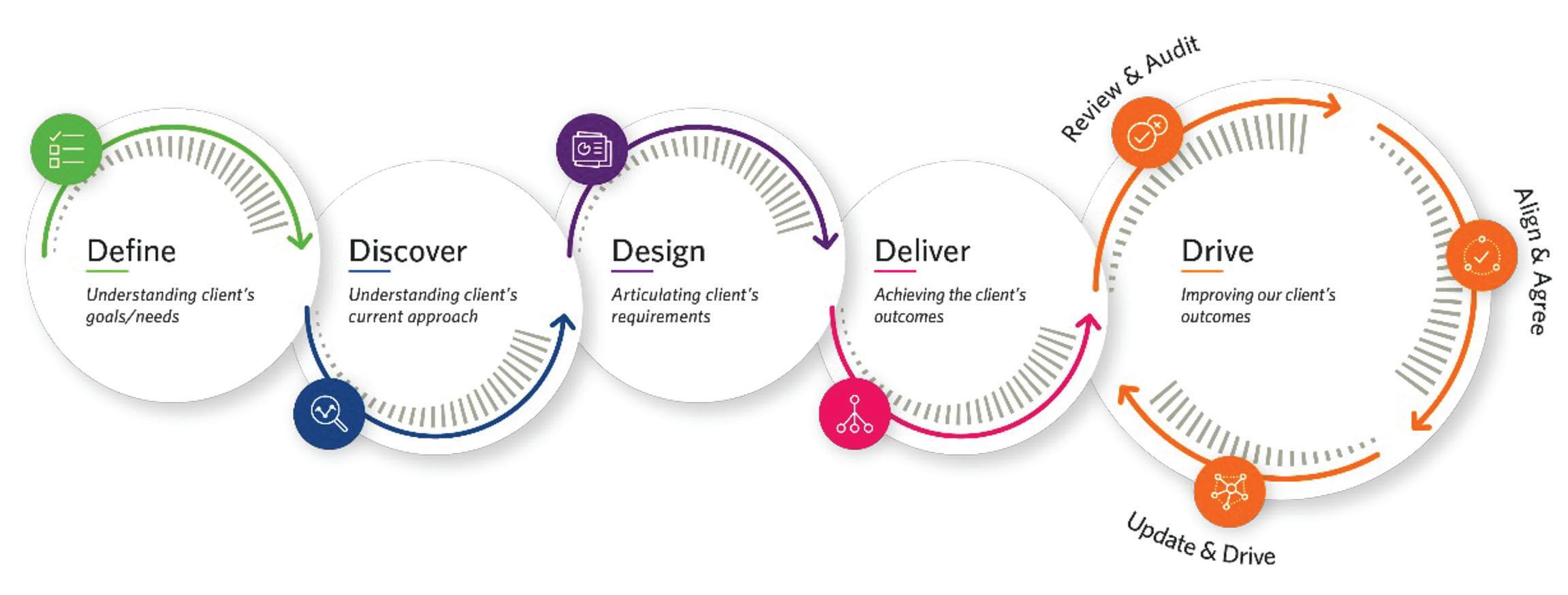
Define
First, we focus on understanding what the need is. This is crucial, as often our clients don’t know this fully themselves. What are our client’s goals and objectives? We define the scope and identify the key stakeholders.
Discover
Then we carry out a thorough discovery phase. We engage with stakeholders from different parts of the business and at different levels of seniority to try and paint a full picture of what the current situation is, where the pain points are and who might be impacted by a potential change to the status quo. This phase also helps to either validate the client’s original goals or inform changes to them.
Design
In the design phase we set out the plan. We consider the processes and protocols, define roles and responsibilities and any technology requirements as may be applicable.
Deliver
We then deliver against our plan, supporting people through training and bringing them along the journey.
Drive
Finally, we drive success of what we have delivered by checking in, reviewing what we’ve done against the original client goals and gathering feedback from key stakeholders to ensure any changes are accepted and well embedded.
Once we have the why outlined from the Define and Discovery phases, the rest essentially boils down to:
1. Say what you’re going to do (design)
2. Do it (delivery)
3. Say what you’ve done (drive)
And this isn’t just once. This is repeatedly done, with regular check ins, building that trust and bringing the client on the journey.
In essence for us it is about building a relationship with our clients and guiding them through each step of this journey, explaining the pros and cons of each option, sharing our experience and generally providing as much information as possible to enable our clients to make more informed decisions.
Being clear on the journey, building a trusting relationship and keep repeating back why we are on this journey, what we have done, what we are doing and what we are doing next. So, the next time someone requests ‘BIM’, it won’t be a panic order – even if the coffee order still is.
Floriano Ferreira is Associate Vice President and Director of Building Data Management / Digital at HDR. Floriano joined HDR in 2019, having gained experience over 15 years working in the Research & Development, Pharmaceutical, Food & Beverage, Manufacturing and Infrastructure sectors. Heading up the Digital and Information Management team. He brings extensive experience in implementing BIM standards and processes, leading teams to drive successful digital strategies which result in exceptional project outcomes and improved long-term asset performance. Stephen can be reached for comments or questions at Floriano.Ferreira@ hdrinc.com.

Anjuli Jackson is Senior Principal Consultant of Building Data Management / Digital at HDR - 9 years with a major UK contractor as a Civil Engineer sparked a passion for driving efficiencies in the construction process, naturally leading Anjuli towards Building Information Modelling (BIM) and digital ways of working. Since joining HDR in 2019, she has been focused helping clients to articulate their BIM goals and develop their own digital strategy, driving the culture change to support this, in addition to driving the HDR Digital Strategy and adoption of the ISO 19650 standard across the UK business to continue providing excellent and industry leading support to our clients. Stephen can be reached for comments or questions at Anjuli.Jackson@hdrinc.com.

3ds Max Standards

One of the essential parts of production in any environment is repeatability. Repeatability ensures that the same high-quality output is consistently produced. When a process is repeatable, the same inputs will always result in the same outputs, which helps to eliminate variability in the production process. That is important because it allows a
company to predict and control the quality of its products, which is crucial for customer satisfaction and business success. In addition, repeatability helps reduce waste and defects, leading to cost savings and increased efficiency. That is true when working with 3ds Max, as is anything else, and the way to achieve repeatability with 3ds Max is through standards.
Standards are an essential part of the 3ds Max software, as they help to ensure that the software is used consistently and effectively by all users. These standards can be used to guide how users interact with the software, as well as how they produce and present their work.
Several standards are relevant to 3ds Max, including technical, visual, and organizational standards.
TECHNICAL STANDARDS
Technical standards are designed to ensure the software is used consistently and reliably. That includes things like naming conventions for objects and materials, as well as guidelines for how to set up and organize a 3ds Max scene. Adhering to technical standards can help reduce errors and improve efficiency, as it ensures that all users work with the same rules and guidelines.
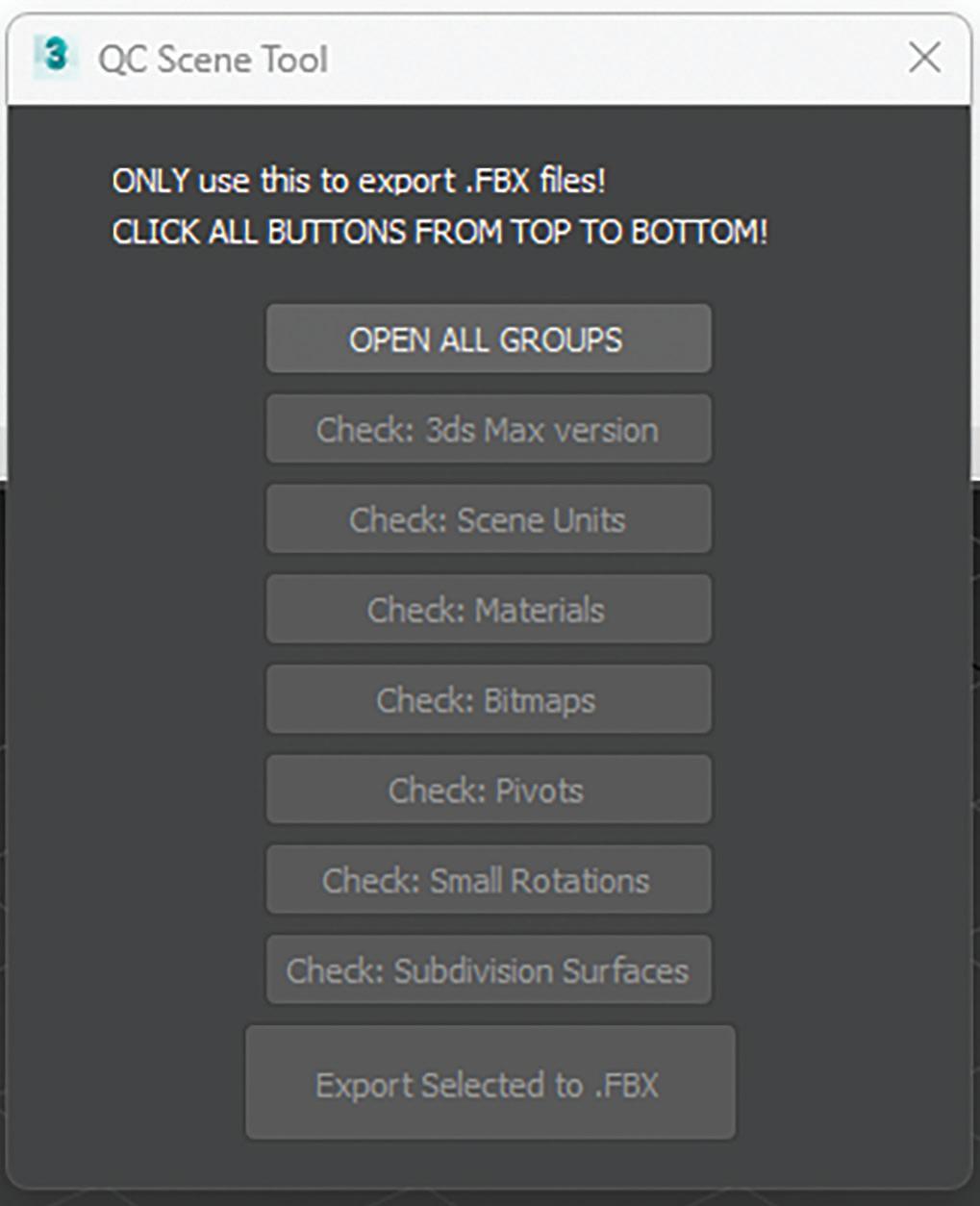
Technical standards are beneficial for automating tasks where assets are being used in more ways. One asset might be used in a simple render, a mobile application, and a presentation on the web. Having technical standards directs users to produce assets in the same fashion, allowing a larger pool of people to contribute and the ability to automate procedures. For example, the 3ds Max script displayed in Figure 1 demonstrates a tool that verifies the following:
• Objects are correctly named and grouped
• The correct version of 3ds Max was used
The scene units are correct
• The standard material was used
• Proper textures are plugged into the material
• Pivot and transforms are corrected
• Reviews the modifiers
Exports to FBX using the proper settings
The tool identifies failures to ensure anyone working on projects follows the same procedures and allows teams to QC operations while ensuring consistency with training and simplifying tech support.
VISUAL STANDARDS
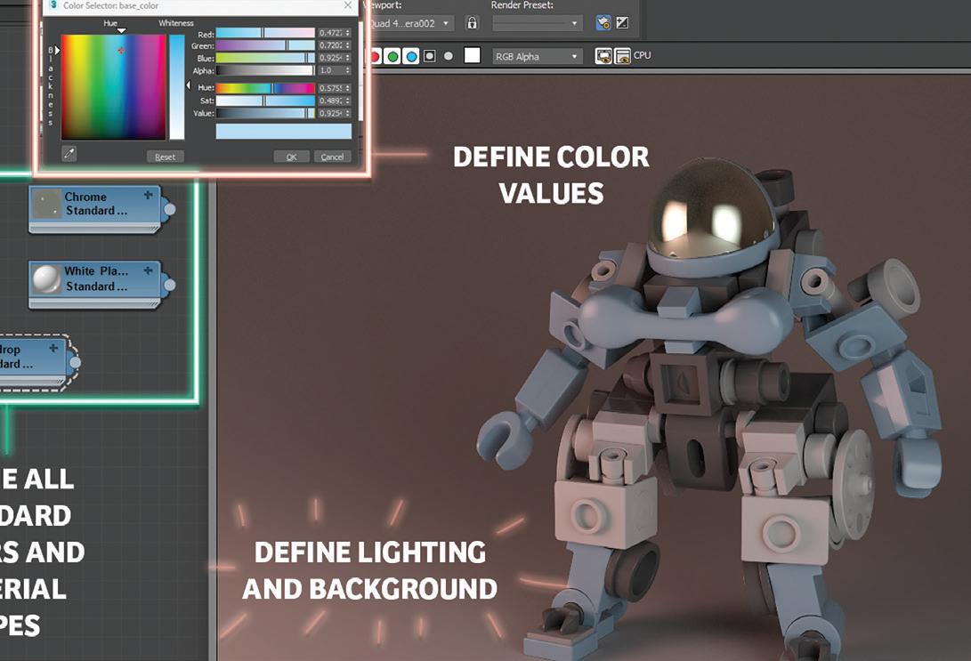
Visual standards like those displayed in Figure 2 are used to ensure that the visual appearance of 3ds Max projects is consistent and professional.
That includes color schemes, lighting setups, and other visual elements to create a cohesive and aesthetically pleasing final product. Adhering to visual standards can help create a strong brand identity and ensure that all projects produced with 3ds Max are of the highest quality. You’ll want to define these standards in as much detail as possible to help users be most efficient while adhering to the same visual bar.
ORGANIZATIONAL STANDARDS
Organizational standards are used to ensure that 3ds Max is used in a way that is consistent with an organization’s overall goals and objectives. This can include things like workflow processes and guidelines for how to collaborate with other team members. By following organizational standards, users can ensure that their work is aligned with the organization’s larger goals and that it fits into the company’s overall workflow.
These can include:
• Workflow processes: These are the steps that are followed when completing a task or project within an organization. These processes might include guidelines for how to receive and respond to requests, how to prioritize tasks, and
how to communicate with team members and stakeholders. These can be complex procedures or simple directions like maintaining the modifier stack.
• Collaboration guidelines: These are rules or best practices that are followed when working with other team members or departments within an organization. These guidelines might include protocols for communication, sharing resources, and resolving conflicts.

• Branding guidelines: These are rules or guidelines that are used to maintain a consistent brand identity within an organization. This might include guidelines for using logos, fonts, and other visual elements in marketing materials and other companybranded materials.
• Security protocols: These are guidelines that are used to protect the security of an organization and its assets. This might include rules for password management, access to sensitive information, and handling confidential documents.
• Legal and ethical guidelines: These rules are designed to ensure that an organization complies with laws and ethical standards. This
might include guidelines for how to handle sensitive information, how to handle conflicts of interest, and how to respond to legal or regulatory inquiries.
Overall, standards are an essential part of a team using 3ds Max software, as they help to ensure that the software is used consistently and effectively by all users. By following technical, visual, and organizational standards, users can produce high-quality work that meets their organization’s and industry’s standards while achieving repeatable results.
Brian Chapman is a 3D Artist in Las Vegas with an extensive history of building content for AEC, game, film, and software development. Brian holds various degrees and certifications in art, graphics, media, and web, with experience in design and application development. Brian can be reached procadman@ pro-cad.net



Standards make the CAD world much more organized, and I hope that at least one of these apps will help you along the way!
The Autodesk App Store is full of these types of apps, not just the ones I mentioned, so make sure you search the store, as I’m sure you will find many apps that will help you work smarter, not harder, when it comes to using and building standards for your workflows. Also, bear in mind that Autodesk also has numerous apps of their own that address standards as well. So, on that note, here are this month’s picked and mixed opportunities to advance your skills, processes, and workflows with the most current industry-related software and hardware updates available.
CAD STANDARD
https://apps.autodesk.com/ACD/en/Detail/Inde x?id=7129935601786766404&appLang=en&os= Win32_64
Autodesk AutoCAD

Version: 2022, 2021, 2020, 2019, 2018
Autodesk AutoCAD Architecture
Version: 2022, 2021, 2020, 2019, 2018
Cad Standard revolutionizes how you work with standard items such as layers, dimension styles, text styles, line types, and blocks from any external Autodesk® or AutoCAD® file (DWG). With Cad Standard, you easily access standard items on-demand, thus negating the need to have these items already in your drawing.
Individual users or large user groups can start benefiting from Cad Standard immediately after installing it, with no setup required. Cad Standard allows each user to access standard items from centralized existing standards files, thus simplifying how you work and manage with standards.
We have all been there when standards are needed in our AutoCAD drawings. Cad Standard gives you much more flexibility in your DWG files.
FAMILY TYPE MANAGER - STANDARD
https://apps.autodesk.com/RVT/en/Detail/Ind
ex?id=5091286671354346366&appLang=en&o s=Win64
Autodesk Revit
Version: 2023, 2022, 2021, 2020, 2019, 2018
Family Type Manager Standard is data management system built in Excel and designed for Autodesk® Revit® users, content creators, and manufacturers. The application was purpose-built to automate many of the time-consuming tasks related to updating and creating Revit family content. The program bi-directionally imports and exports Revit family data with Excel for the management of Type Catalogs and Lookup Tables.

The Standard version includes Type Catalog Manager & Editor, Lookup Table Manager & Editor, and the document management workspace Scratch Pad. A separate PRO version is also available for purchase.
An amazing part about Family Type Manager is that it works with any Revit version Year and Language! Revit families and project files can also remain open during editing for real-time rapid testing and deployment during content creation. You also do not require Revit to edit content. This allows teams to easily share Excel data files with any other personnel or customer.
With Family Type Manager, you can quickly update Type Catalog and Lookup Table values and parameters, use rules to name your family types, link family data with external data sources, run error checking before importing into Revit, and bulk converts your content to different languages and units of measurement values. You can also generate single, multi or full list Type Catalogs, create Master Type Catalogs and Lookup Tables, share data with other non-Revit users, sort and column organize data, convert data to shareable Excel files, use regional languages and formatting, and many more features.
Note: This app uses a custom installer (rather than the standard app store installer).
There’s ALWAYS a need to manage and standardize your Revit families. This is a great app to help you do this.
CADS REBAR EXTENSIONS FOR AUTODESK® REVIT® - 2023

https://apps.autodesk.com/RVT/en/Detail/Inde x?id=434828368220145570&appLang=en&os= Win64
Autodesk Revit Version: 2023
Save time by automatically generating reinforcement in Revit using the free unlimited trial of CADS’ Extension Tools for a range of standard concrete structures. Select the structural concrete elements to be reinforced, launch the appropriate tool, or select the automatic generation tool. Specify the parameters to be used when reinforcing
the structure. Supported concrete elements include beams, columns, continuous footings, parapets, pile caps, concrete piles, retaining walls, slab corners, slab openings, spread footings, wall corners, and walls.
The Rebar Extensions were originally developed by Autodesk® but due to their close partnership with CADS, they have asked us to develop and maintain the extensions. These extensions work with CADS RC3D for Revit which is a Revit extension designed to enhance the placement, annotation, and bar marking of reinforcing steel in all kinds of RC structures. CADS RC3D takes the 3D modeling functionality of Revit to the next level allowing rebar to be divided up into particle groups (bar ranges), bar marks to be created and managed, detailed reinforcement (shop) drawings to be created with a single click! Bar bending schedules are automatically created and material lists exported to external production software file formats such as BVBs, aSa, Soulé, and Excel.
CADS Markup also comes with CADS RC3D and allows structural engineers to annotate a Revit model with reinforcement information to convey the design intent to reinforcement detailers effectively avoiding the process of manually marking reinforcement regions on printed general arrangement drawings.
Note: This app uses a custom installer (and not the standard App Store installer).
Reinforced concrete and rebar require close standardization. CADS RC3D certainly makes sure you have this under control!
GETRADIUSPOINTS
https://apps.autodesk.com/CIV3D/en/Detail/ Index?id=857845778657685520&appLang=e n&os=Win64
Autodesk® Civil 3D®
Version: 2019, 2018, 2017, 2016, 2015
The GetRadiusPoints app is an Autodesk® AutoCAD® Civil 3D® plugin that modifies a curve table style and inserts columns with the center point (northing and easting) of curve segments that are not part of an alignment, including AutoCAD® arcs and parcel segments.
Note: This app uses a custom installer (and not the standard App Store installer).
Radius points in Civil 3D are fundamental to standards and this app allows you to modify curve tables, segments, and place columns. EXACTLY what you need, right?

If you have some news to share with us for future issues, please let us know. Likewise, if you are a user of a featured product or news item and would like to write a review, we want to know. Drop me a line at: shaun. bryant@cadfmconsult.co.uk. We’d love to hear from you!
AUGIWORLD brings you recent developments in Autodesk and related software items
BricsCAD, Standards, and the Grocery Store
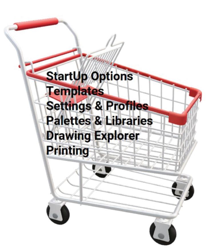
We have all been to the grocery store or supermarket, and I would be willing to say you have encountered a time or two where the items you are searching for are not available, have been moved, or maybe even discontinued. That’s frustrating. Better yet, walk into an unfamiliar grocery store; talk about feeling lost, confused, and only then you are reduced to asking the 16-yearold kid where to find the ketchup. Finally, you have arrived in the condiments aisle only to discover the mayonnaise, mustard, pickle relish, and ketchup shelves are all combined, mixed up, and have zero organization. What you thought was going to be a quick trip has now resulted in a 15-minute wave of frustration.

So I will ask, “Why do you like your grocery store?” Are they organized? Do they make it easy to locate what you need? Are the items easily accessible? How easy is it to checkout? Let’s now ask, are your CAD tools easy to locate, well organized, and easily accessible? I understand. Some people don’t care at all. Don’t make that miss-steak. Lettuce (BrisCAD) help you.
THE CAD PLATFORM
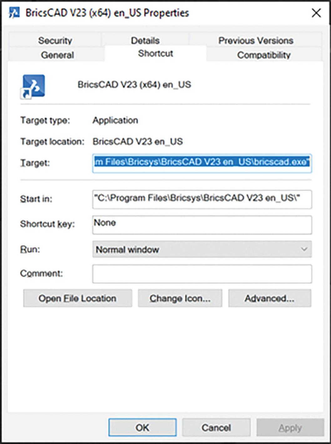
When entering the grocery store, you can choose to carry a basket or push a shopping cart. While the basket may be a quick and easier option, it can get bogged down, and become very heavy if it is overloaded. The shopping cart might be a bit slower overall, however, if the task requires a heavier load, the shopping cart is designed to handle it. The same applies to your CAD software. Ensure your staff has access to the software design tools they need. In the same manner, not everyone needs the full-blown design suite if they are only using spellcheck which is why BricsCAD offers multiple license levels, from Lite and Pro to Mechanical and BIM, all in easy-to-use dwg format. (See Fig. 2)
START-UP OPTIONS
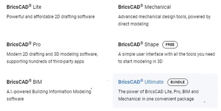
When starting BricsCAD, you can add arguments or switches to the properties target. These arguments or switches can be shared across the organization within this shortcut providing consistent licensing, templates, profiles, &/or start-up LISP scripts when the program opens. (See Fig. 3) BricsCAD Help Center is a staple and an excellent resource for Start-Up options.
TEMPLATES AND FILE FORMATS
Templates set the environment and make the user experience efficient. BricsCAD offers a myriad of template options. Drawing Templates (.dwt) and Sheet Set Templates (.dst) are just a couple of ways to ensure project consistency.
Setting up a drawing template in BricsCAD is a piece of cake. Start with a new drawing. Include standard fonts, lineweights, linetypes (.lin), layer names, layer colors, text styles, dimensions styles, standard blocks STB/CTB, page setups (.pc3), or sheet borders, and you will want to set the drawing units and scales. Next, save the “.dwg” as a “.dwt”. Continue to refine as needed. Keep in mind, you can always have more than one template. Track changes that relate to other templates and make the appropriate revisions.
Sheet Set templates (.dst) are used to organize the project. Standard drawing subsets can be created and stored. Additionally, sheet borders can be setup to pull information from the Sheet Set Manager, populating the attribute field text. This drastically reduces the amount of time floundering, fishing and opening drawings as well as the time it takes to modify each text item.
In addition to the two previously mentioned template file formats, Communicator for BricsCAD seamlessly imports geometry & PMI data from
all major CAD applications. Having an internal standard process for importing/exporting data is soup-er important. For more details on Communicator, visit https://www.bricsys.com/en-us/communicator
SETTINGS AND PROFILES (.ARG)
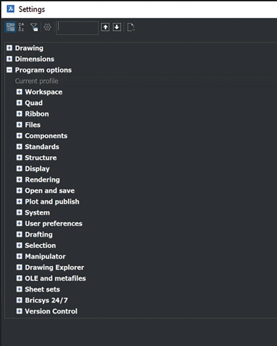
Settings control a wide variety of options. From template file pathing and screen colors to crosshair size and plotting outputs, users can set then share these settings by exporting the profile (.arg). This can be easily accomplished by using the User Profile Manager within BricsCAD. It is also available from the start menu, without having to open BricsCAD. Use the “Export” option to create a standard .arg that can be distributed companywide then “Import” the .arg once again using the User Profile Manager. (See Fig 4) & (Fig. 5)

TOOL PALETTES AND LIBRARIES
BricsCAD Tool Palettes and libraries provide immediate access to a host of CAD tools and design features. This could be commands, blocks, hatches, and components, either out-of-the-box and/or import of custom tools. Palettes and libraries are an excellent way to stay consistent for everyone in your design group. In addition, the time difference accessing these tools from the palette or library versus searching the entire network or directory for the exact folder of the item is a major time saver. These features also offer the ability to sort and organize the tools according to workflow, industry, features, project and/or process.
DRAWING EXPLORER
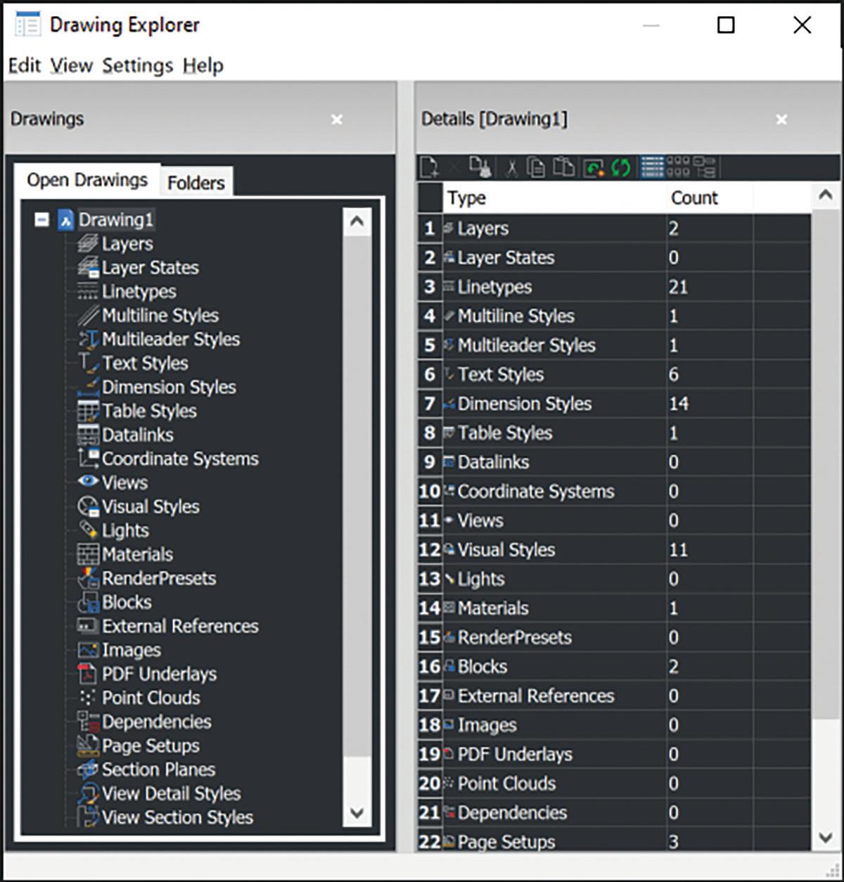
BricsCAD Drawing Explorer enables all the key aspects of a drawing to be managed in one singular location, providing full visibility of the properties within the drawing. Drawing Explorer is a fast, effective way to configure any drawing. The learning curve for new users isn’t steep because it’s one single tool for users to become familiar with. Work will be more standardized, and project drawings will be more consistent. If you like Autocad Design Center, you will love BricsCAD Drawing Explorer. (See Fig. 6)
PRINTING
In the December 2022 issue of AUGIWORLD, Brandon Cole provided an extensive comparison between the STB/CTB plotting options. Keep in mind, while the STB/CTB filenames might be the same, often users will modify the plot settings
without sharing the STB/CTB which leads to inconsistency between users. Plotting is the equilvalant to the checkout lane. Setup the plotting environment for an easy checkout. Establish file standards and protocol ensuring proper plotting between users. This also pertains to page setups (.pc3 files). As previously mentioned, these can be set in the template.
COMMUNICATION
Outside of the CAD software environment, communication is as important as the standards themselves. Involve your staff in making decisions, and continue clear lines of communication on why standards are important within the organization. Depending on where you currently reside with establishing and enforcing standards, best practices, and workflows, you may need to hop on the office intercom and announce a “Clean Up in Aisle 5.” And while that is not ideal, it’s better than tracking the figurative mess throughout the project life-cycle.
CONCLUSION
Standards and best practices are very common, not only in the engineering, construction, and manufacturing industries but even in the grocery store. Most likely, that is what you like about the grocery store you regularly visit. The experience is now efficient, familiar, and quick because the store is well organized, planned, and thought out. Strategize your standards, and provide easy access to the supporting tools for your end users. After all, they are the consumer. Ultimately, the daily CAD experience will be as easy as walking into your favorite grocery store. Thanks for pudding up with me. Have an egg-cellent day.

Mr. Craig Swearingen is a Global Implementation Specialist and Consultant with Bricsys and has over 20+ years in the CAD and Engineering Industry. In his current role, Craig provides migration and implementation guidance, management strategies, and technical assistance to companies who desire a compatible alternative CAD software solution. Craig spent 19 years in the civil engineering world as a technician, Civil 3D & CAD power user, and became a support-intensive CAD/ IT manager in high-volume production environments. Craig is a longtime AUGI member (2009), a Certified Autodesk AutoCad Professional, and enjoys networking with other CAD users on social media. When away from his desk, you can find him at a Pearl Jam concert or volunteering with Little League Baseball.

A Network Tool Palette Manifesto
In the ever-competitive world, leveraging available tools efficiently will undoubtedly bring benefits to the bottom line. Making those tools available to a workforce in a way that enforces the company’s design language will increase the overall stability and quality of the product. In manufacturing, the concept of production line and tooling defines the tangible workspace that creates the widget. Companies measure efficiency by how many screws or welds are installed and the time related to those operations. Great lengths are taken in the optimization of these systems. Why not apply similar concepts to CAD production and management?
The ability to define the cost savings related to efficient CAD management and execution is not as easy to quantify as the number of bits and bobs a widget has. We hover in the metrics reserved for marketing and training, a space where a linear graph does not exist. One cannot simply assign more training or publish more advertisements and expect “X” more revenue. But we do know that when any of these areas are neglected, the company will suffer. This pain can come in the form of lost profits, lost employees, unrealized projects, or the loss of confidence in the company by its workforce.

To contain the design language of a company, CAD management and committees will develop an extensively detailed novel of CAD Standards, with the expectation that all users abide by it. If you take that book and instead use it to back up automation and the development of tools and styles that enforce those standards, the reference materials a user needs can be reduced to a single page
that lives under the keyboard for quick reference. Developing the virtual assembly line, and tooling the CAD workforce with standards, is a much more efficient way of production than publishing literature for users to memorize. If all the bits and bobs are ready for the user to pick from, less time is spent trying to remember how something should look, and greater focus and energy is given to the accuracy of the design. Let me be clear, I believe that a company’s standards should be backed up in writing and available for all users to access, but the presentation should be streamlined. This approach has far-reaching effects, from the quick onboarding of a new user to ad-hoc teams that need to exist for a few weeks during a production push.
I want to help engage you in a conversation that I firmly believe addresses many production and execution bottlenecks. A tool that resides in AutoCAD and has been there since 2005. This conversation should be between your trusted CAD experts and management. I urge management to allow the time and resources for the CAD team to investigate and develop a more streamlined way of presenting the workforce with a meaningful and standardized tool set, a promise that your company will be better in the long run. If you are part of an AutoCAD workforce or are the manager or owner of a company with one, you are losing time and money if you don’t use a Networked Tool Palette. That’s a bold statement so allow me to paint a picture, one that I’m sure has elements you will find familiar.
• You work in a company that acquires a job and is required to produce a set of plans as a deliverable. During the production of these
plans, a set of notes, text, or standard detail needs to be included to convey the intent, or cover liability concerns. Maybe you need to simply format the plan with a border and page title required by the agency that will review the plans. Instead of recreating everything from scratch, a previous job has all that information already developed. The information is copied out of the previous job’s files and pasted into the new files.
There are two things immediately obvious to me. The time taken to find the old file and information is a waste. Standard blocks, details, and notes should be readily available to users without leaving the CAD workspace or active drawing. More important is the danger of using data that has been in another drawing. As innocent as copying may seem, the new files’ fate may just have been sealed. All too often, files from old projects contain things that will cause issues regarding performance and stability. Those things, I will refer to as “gremlins”, cost time and effort thereby affecting the profitability of the project. An unseen cost is the confidence of the workforce. When frustration sets in because of file stability or performance, users will murmur. If the problems are bad enough, they may look for what they perceive as a more stable workplace. The unfortunate pattern will continue until the root of the issue is addressed, which is the quality of information within the production cycle.
• Your company has an extensive library of details and blocks that have been crafted over many years of experience. They look good, and the company is proud of them. The details are saved on a shared location that is available to all users in the company. Users that have become used to the details have set up a shortcut or another way to browse to the shared location quickly to insert a detail or block.
This scenario seems to be a fully formed workspace that cannot benefit from the use of a networked Tool Palette, but alas it can. When onboarding a new user, knowledge regarding the location, organizational conventions, and placement into the drawing must be conveyed. This is not a major issue if the company consists of a small number of employees with little or no turnover, or a company that does not concern itself with future growth. And again, the time to navigate from the active drawing is like the leaky toilet that drains the water
tower. The time savings in setting up a Tool Palette that includes all of a company’s blocks and details, and setting the default layer, color, and other parameters, will be realized as long-term gains in timesaving while positioning the company for easier onboarding and workforce growth.
• As the CAD manager of a multi-node workforce, silos of information relating to the region where an office is located have been built up over the years. A new project has started that will require the workforce to expand to twice the normal size for four months and then contract to its original size. Since your company has 200+ AutoCAD users across all offices, hiring is not necessary. The expansion could be carried out on an as-needed basis by users that are light with work. The only problem is that the offices’ workflows and standards are so different that there will be a strain put on the temporary virtual migration of users from one team to another because of a “lite onboarding” of the team member. A dedicated team of users must be selected to remain on the project until the contraction is possible.
Again, this doesn’t seem to be a place where a networked Tool Palette can offer a benefit. So let us think about the standardization that takes place as a natural by-product of cultivating and deploying a CORE Tool Palette across a large and co-located workforce. By placing a universal and, more importantly, standardized set of tools at the fingertips of the entire CAD user base, you will create a workforce that can spin up teams within minutes during a simple meeting. This type of agile concentration of effort from within looks more like a
MAKING TOOLS AVAILABLE TO A WORKFORCE IN A WAY THAT ENFORCES THE COMPANY’S DESIGN LANGUAGE WILL INCREASE THE OVERALL STABILITY AND QUALITY OF THE PRODUCT.
Customization
task assignment rather than a project commitment. Users that are lite with work one day, can pull from a list of tasks or redlines that have yet to be completed on multiple projects. Implementing a task board of available work reduces the time users spend looking for something to do while increasing confidence in the company’s stability and leadership. In my company, we are using a CORE Tool Palette as a backbone to then craft regional Palettes. The CORE Palette includes buttons that will load a regional palette as needed to complete tasks specific to an area. Regional offices can load their palette by default in addition to the CORE by way of a regional acad.lsp file.
Conversations that will happen when developing a Tool Palette that affects many users will always benefit the company. You may uncover fallacies in workflows or production that require hard truths to be spoken, which will systemically change everything in the way your company works. You may find faults and errors in drawings that have unknowingly plagued your filesystem with gremlins that have siphoned thousands of dollars in profits over years of work. Or you may find incremental and unrealized benefits that will create sweeping time savings across the company. I have yet to implement a Networked Tool Palette in a company that, after using it, wished to go back to the ‘old way of doing things’.
Please note that accomplishing a fully realized and fluid, company-wide system is not trivial. The process is not quick and easy. An additional amount of time, greater than zero, will be required as an ongoing effort to maintain and enhance the Palettes. Much of the time cost is, of course, at the beginning of the journey, and in direct relation to the complexity/ flexibility of the system to be developed.
I firmly believe that a CORE system, one that is nimble and pruned, is the best one to be implemented. Focusing on the absolute standard branding, the look and feel, the “Common Relative Environment” or “CoRE” of how we present ourselves as a unified, stable, and competent workforce, should drive the development of this system. Everything else should be added with extreme prejudice, and only when needed to reduce the potential for scope creep in the system.
I’m grateful to all the companies who have allowed me to deep dive into the psychology, methodology,
and ethics of plan production in my quest for perfect CAD Management. They have realized the benefits of the trust and tangents they have allowed me. None of the topics I am covering in my CAD Management series are simple linear problems to solve. The human component will always be the most confounding factor. An equation I am grateful to be part of.
You can find more from me about Tool Palettes on the Autodesk Voices blog here: https://forums. autodesk.com/t5/autodesk-community-voices/ networked-cad-management-part-2-tool-palettes/ ba-p/11648914
And the first Networked CAD Management article here:
https://forums.autodesk.com/t5/autodeskcommunity-voices/networked-cad-managementpart-1-support-folder-acad-lsp-and/ba-p/11539259
Daniel Lench started his career as a cabinetmaker/fine woodworker and transitioned to the AEC industry in 2002. A lifelong geek and technology enthusiast, he was hosting a BBS at the age of 13 over a 2400 baud modem. He has had the pleasure of working at the Museum of Florida History as an artisan, building and maintaining exhibits and the museum. With nearly 25 years of experience with AutoCAD, Land Desktop, and Civil 3D, he is passionate about sharing his accumulation of knowledge and workflows. He has acted in the CAD Manager role for 20 years at several engineering firms and consulted with city engineers and remote companies to develop and optimize their Civil 3D environments. A unified company and user experience, along with futureproofing the CAD systems, are the primary focus of what he develops. Daniel currently works alongside AUGI’s very own Todd Rogers at Walter P Moore and can be reached at dlench@ walterpmoore.com or by cell at 979.575.6717.


CAD Manager Confessions: Crushing Your 2023 Goals
Is it just me or did 2022 go by way too fast?
Due to time passing us by so quickly, I am sure you will reflect on the past 12 months and realize you may have missed the target on your goals for various reason.
On the personal side, I am a father of three amazing kids. Deion is 22, Kiki is 17 and a senior in high school, and Kaela is 15 and a sophomore in high school as well. I am married to my high-school sweetheart, Teresa, where we just celebrated our 25th wedding anniversary this past September.
Also, we moved from Oregon to Texas for my amazing job at Halff Associated in the summer of 2021, so 2022 has had its share of ups and downs as we settle into new schools, jobs, and our new Texas community.
Through all of that transition we have no regrets as the future is bright and wide-opened as we move into this new chapter of life, so the struggle is real when it comes to finding the time, energy, and focus to conquer our personal goals.

On the professional side, I’ve had my share of challenges as I continue to settle into my new role within my new company and continue to be the leader of change, so I’ve been working on leaning on the framework I am sharing with you today to help me reach my own goals to be the best natural version of myself.
So let me ask you this, what kept you from your goals this past year…
• Starting a new job?
• Moving to a new city or state?
• High utilization? Lack of planning?
• Higher than normal support tickets?
• Too much drama within your CAD Team?
• How about “busyness” work?
Or let’s keep it real for a second… maybe you are bored at your job and ready for a change?
Let the that simmer for a moment…
Once you identify the source and/or sources that are getting in your way, you will be able to create a more proactive plan to help protect and preserve the integrity of your goals to give yourself the opportunity to take inventory to right any 2022 wrongs to make 2023 even better.
Here are 10 steps in conquering those goals once and for all.
STEP #1:
REVERSE-ENGINEER THE END GOALS
What would a successful 2023 look like to you? Once you have identified what that looks like, you can then plan how you are going to achieve that plan.
When it comes to creating the plan for crushing your goals, take small steps regularly towards your ultimate goals.
In time, the goals that seemed so daunting before will be achieved much quicker than you thought possible.
STEP #2: MINDSET
You are human. Falling short is part of the process. The key is to pick yourself up quickly after missing a goal, and then reassess why you missed the goal so that you can pivot to get back on track ASAP. So don’t be too hard on yourself!

STEP #3: SET REALISTIC GOALS
Stop trying to be a Superhero and overloading yourself with too many goals, especially at your day job.
Keep in mind that you will be measured and judged based on whether you accomplish those goals or not.
Also, make sure that your goals align with your career ambitions.
Try learning a new skill to make you a better and more marketable professional within the industry, developing and implementing a new workflow or process that helps improve efficiency within your CAD Team or company, or finding time to network more this coming year.
By setting realistic goals, you position yourself to successfully achieve all your 2023 goals.
WHEN IT COMES TO CREATING THE PLAN FOR CRUSHING YOUR GOALS, TAKE SMALL STEPS REGULARLY TOWARDS YOUR ULTIMATE GOALS.
CAD Manager
STEP #4: IDENTIFY SPECIFIC GOALS
Now this may seem like a “duh” moment and very basic concept, but I have mentored others who didn’t really know how to articulate their goals clearly.
They tend to set a general goal like, “I want to be more efficient with software.” Okay, so what does that really mean?
I did say identify your “specific” goals, so get more granular!
If, for example, your goal is for more software training, pick specific concepts you want to learn, such as Getting Started with MicroStation, Introduction to Dynamo, or Revit for Advance Users.
Be specific, and then go find the exact resources that will help you reach your goal.
STEP #5: WRITE YOUR GOALS DOWN
Once you have identified your specific goal(s), write them down.
Research has shown that the act of writing increases the likelihood that you will accomplish your goals by about 42%, so there is power in writing your goals down.
You can post a list of your goals on your desk, or even screenshot them and make it your phone background image to help keep them top-of-mind.

Writing and sharing your goals is a declaration and commitment to taking your next-level potential seriously.
Getting others to rally behind you can be the encouragement you need when you feel like you are falling behind and need some support and additional accountability.
If you want some major accountability, I dare you to post it to social media and maybe tag me to let me know. I’ll be your accountability buddy.
STEP #6: PUT IT ON YOUR CALENDAR
Busyness often gets the best of us, so to make sure we reach our goals, we need to put it on our calendars.
Figure out how much time you will need and update your calendar accordingly. For example, do you need 30 minutes a day? or 90 minutes a week?
Whatever time you think you need, break it down and put it on the calendar today.
STEP #7: RESPECT YOUR CALENDAR
Putting your goals on your calendar is good, but respecting that personal goal appointment and using that scheduled time to progress your goals is key to crushing it.
Think of these goal appointments like you would think of a meeting with your boss or CEO of the company or client.
Respect your goal appointments, and you will see the difference over time.
STEP #8: REVISIT GOALS MONTHLY
Again, project work and busyness often gets the best of us, so at the end of the month, revisit your goals to ensure you are on target.
WRITING AND SHARING YOUR GOALS IS A DECLARATION AND COMMITMENT TO TAKING YOUR NEXTLEVEL POTENTIAL SERIOUSLY.
STEP #9: PIVOT & RESET
If you don’t reassess your goals regularly, you don’t allow yourself the proper time and space to pivot & reset should your goals need to change.
Being on top of your goal’s progress really does allow you to roll with the punches that get thrown at you daily, as it provides time for corrective action.
If you aren’t on top of your progress, time will get away from you and all those milestones you planned will come and go with no progress towards your overall goals.
Once your back is against a wall, it can be really hard to recover, and you don’t want to ever put yourself in that position, ever.
STEP #10: OWN IT & NO EXCUSES
At the end of the day, the effort that is put into achieving your goals is up to YOU. Period.
Setting realistic goals that are geared toward your career ambitions will give you greater and deeper ownership, so you will truly be vested in accomplishing them.
And I know you don’t want to let yourself down.
If your boss or company gives you a less desirable goal but it’s a very important to the firm, make sure to make that a priority, since your job performance will be measured by it.
You want to make sure you position yourself well to maximize the outcome by achieving that goal—you want that raise or promotion, after all!
CONCLUSION
Consider the 10 steps above when setting and planning your 2023 goals, and make them your own to achieve greater success this year.
You’ve heard it before: “Success is where preparation and opportunity meet,” so thoroughly plan to achieve your goals.
I am confident that by being prepared, you will see some new and amazing opportunities that might
not have been visible in 2023 when your head was down and your focus was on all the busyness work—when you forgot to preserve the integrity of your goals.
As you plan your 2023 goals, what are you hoping to achieve this year?
Feel free to reach out to me and let me know, since you have a fan over here cheering you on to great success in 2023 and beyond.
Mr. Eric DeLeon has over 24 years of professional CAD experience within the semiconductor and AEC industries. Eric is currently serving as the CADD/BIM Technology Manager at Halff Associates based out of Richardson, Texas. Mr. DeLeon is also the Host of the CAD Manager Confessions Podcast which is for CAD Managers in their purpose of the perfect set of plans. On the podcast, Eric interviews other CAD Manager so the CAD community can learn from their stories and where he also confesses all of his lessons learned, strategies, and his project delivery secrets. Eric is currently serving as an active member of the AUGI Board of Directors. Gandhi once said... "A sign of a good leader is not how many followers you have, but how many leaders you create". Creating CAD Leaders is Mr. DeLeon’s new purposedriven mission, and he is looking forward to helping as many CAD professionals as possible step into leadership roles that help them reach the next level in their careers which will make them invaluable assets to their organizations while helping them master project delivery. Go to www.ericdeleon.com to learn more about Eric’s upcoming CAD Leadership development workshops, coaching, and programs.

Fail Safe
No one wants to think about failing, but I think about it when needed. Failing is part of winning. Most major league baseball players never hit over a .300 batting average. Last year Jeff McNeil of the New York Mets, batted .326. He was an All-Star, Silver Slugger and MVP candidate, one of the best in the Majors. But he did not make it on base most of the time. In fact, most players “fail” to get a hit seven out of ten times at bat. And they make millions of dollars per year.
So, let’s think about failing a bit. It has happened in the past and it will happen in the future. You may have heard the adage… “Fail to plan, plan to fail”. But how about failing to plan for failure? Forgetting that might cause great pain and delay. The Cambridge Dictionary lists fail-safe as, “If something is fail-safe, it has been designed so that if one part of it does not work, the whole thing does not become dangerous.”
I used to work in Process Design, and we always specified control valves to fail-safe. Sometimes they failed open, and others failed closed. You decided which is best. You would not want oil, gas or chemicals to be gushing all over the place is a valve fails.
Some of you may have seen the movie “Fail Safe”. The plotline has a computer malfunction that triggers an order for a nuclear attack. Tension rises as bombers are scrambled and they try to countermand the order. It is a great Cold War movie from the 60’s. You should watch it.
Fail Safe usually is thought of as being automatic. If something bad happens, then this automatically happens. But in technology planning, automatic seldom happens unless it is coded in. you can “code in” fail safe. First you think about failures that might

occur, expected or unexpected. Then you decide what should be done when the failure actually happens. No one wants to fail, and many forget to plan for it.
PLANNING THAT YOU NEVER WANT TO USE
This type of planning is called many things. It may be called a Contingency plan, Backout plan, Backup plan or Rollback plan. Any way you title it, I am talking about what you do when things go off track and are irreparable, unsalvageable, and wrong. You have seen this happen. Something that should be easy, does not go so easy. Something that has worked a hundred times, goes wrong on attempt one hundred and one. It may be a small thing, or a major project. I want to focus on the major derailments. The ones that need to be thought through before you begin the initiative. With smaller ones, you just try again. Or you do some troubleshooting and then try again. But the major ones sometimes go off track and can’t be salvaged. What do you do then? You need to add some time to the positive planning phases to think about the negative side when things may go wrong. You may even want to delay your initiative if your back out plan is not ready yet. It is worth the risk to start an initiative when there is no escape hatch?
Define what might need to be done if things do not go as planned. Discuss what the back out strategy might be. Is it simply starting over with an adjusted plan? Is it stepping back the software rollout? Is it updating other hardware and swapping out what you were trying to upgrade? And how long will it take to execute your back out plan? If you are approaching a deadline for use of the hardware or software you are working on, can you get it operational again by stepping back and get it usable again by the deadline? You need to get agreement on the back out plan and timeline before you start the initiative. That way everyone knows that failing is just a temporary setback and not total failure. You have a plan for contingency that can be used in a worst-case scenario.
THE POINT OF NO RETURN
Sometimes your initiative has a point of no return. Fail safe planning takes that into account and has a decision point for going beyond the point of no return. When you approach and then pass the no return point, everyone should know you are all in. Failing after that point, means not having the
hardware or software functional for an indeterminate period of time. Sometimes you have no choice. You have to move forward. Sometimes you just need to press on.
WHAT DOES FAILURE LOOK LIKE?
A Back Out plan, assuming that when the failure has happened, it is unrecoverable. It is when you are stuck. Dead in the water. No possible hope is left for making progress and you have to turn around. This is not the decision to go to Plan B. Plan B might be part of your rollout as an option to the optimal Plan A. Plan A and Plan B, or even C might work and you can divert to another path when A or B stalls. But an “abort” is a call that is made when everything is failing. Then you have to put things back the way they were before you started.
MAKE THE CALL – ABORT
Time to abandon ship. I am using every metaphor or simile I can to define that the last vestiges of hope are gone. Time to call it quits. Abort. Pull the rip cord. Stop the music. When this happens, you divert to the back out strategy and try to put Humpty Dumpty back together again. When you find that the options list is exhausted and there seem to be no more legitimate ideas to solve the dilemma and get back on track, make the call. Don’t chew up too much time with valiant attempts that can’t pan out. The best plan now is to recover, regroup and retry later. There is no shame in failing when you have made a good plan and execute it well. Somethings just do not go your way. Give it some time, think it through again and reinitiate later. Tomorrow is another day (I am always quoting movies).
Mark Kiker has more than 30 years of hands-on experience with technology. He is fully versed in every area of management from deployment planning, installation, and configuration to training and strategic planning. As an internationally known speaker and writer, he is a returning speaker at Autodesk University since 1996. Mark is currently serving as Chief Technology Officer for SIATech, a non-profit public charter high school focused on dropout recovery. He maintains two web sites, www. caddmanager.com and www. bimmanager.com.

Checking Standards in AutoCAD & Civil 3D
Surprise!! Contrary to what many believe, I do have standards!! However, those mainly apply to CAD Standards and CAD Standards only!
There are a few very simple options for helping ensure that your orginizational standards are being kept. In AutoCAD, there is a CAD Standards Checker you can run for a quick audit of your drawing(s). And in Civil 3D, the Reference Template options have been available to us for a few years to date. Now, these are just a couple of the out-of-the-box solutions, and there is a lot more to a proper CAD Standards setup, but I thought this may be helpful for those that have little to no standards!
CAD STANDARDS CHECKER
The CAD Standards feature makes it easier for others to understand and follow consistent drawing organization practices by maintaining common names and style settings. Standardized drawing organization is particularly useful in collaborative environments where many individuals might contribute to a drawing.
The Standards Checker consists of two parts:

• The Standards file and
• The configuration tool
CONFIGURING THE STANDARDS CHECKER
You may already have a file that houses your CAD standards, as it may be a template that contains all your proper layers, linetypes, and styles. Simply save that file as a .dws or create a new one that contains your standards.
If you work in a multi-discipline environment, you can even have multiple files; perhaps one for each discipline, such as civil, architecture, or MEP (Figure 1).
From the Manage tab of the ribbon, use the Configure tool in the Standards panel to add your .dws file to the drawing.
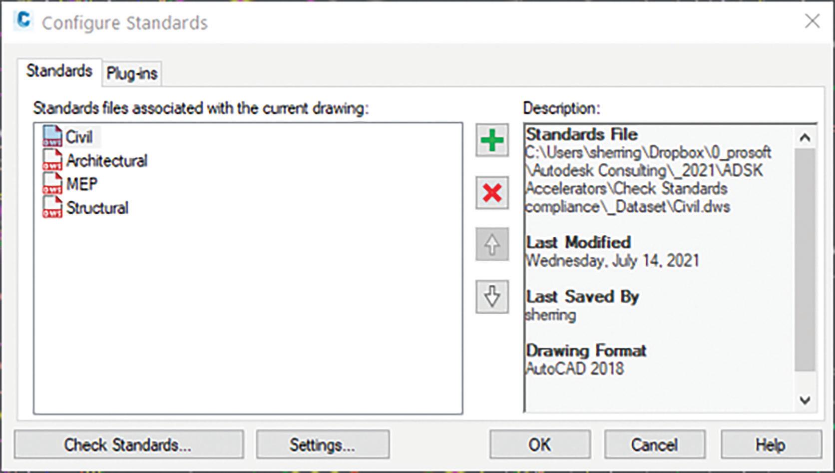
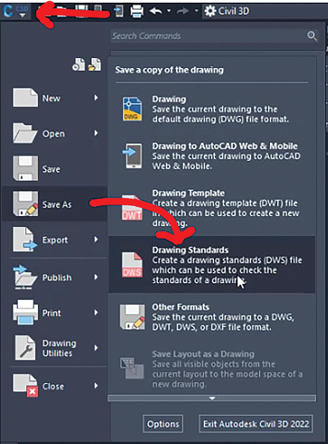
From the Standards tab of the configuration dialog, you can add, remove, or re-order your standards files. Much like an Xref, the .dws standards file will stay attached to the drawing until you remove it, so you can actually build these into your templates (Figure 2).
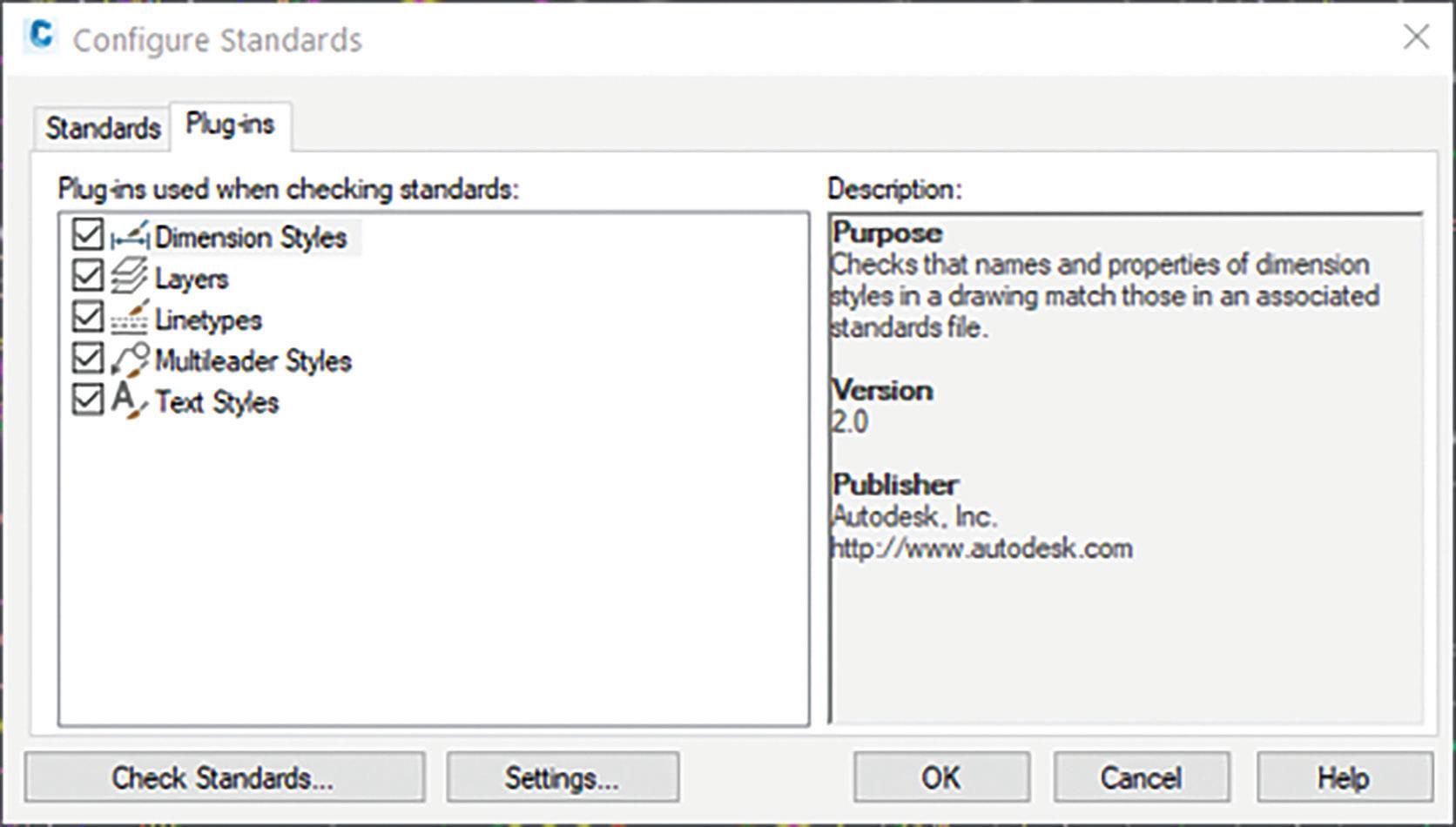
The Plug-ins tab allows you to customize what objects will be checked in your drawing. Options are Dimension Styles, Layers, Linetypes, and Text Styles.
Simply check or uncheck the plug-ins that you want. The description box on the right will tell you exactly what feature of each plug-in will be checked (Figure 3).
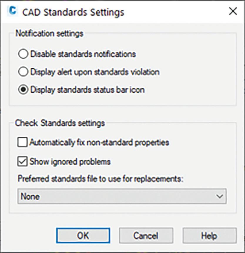
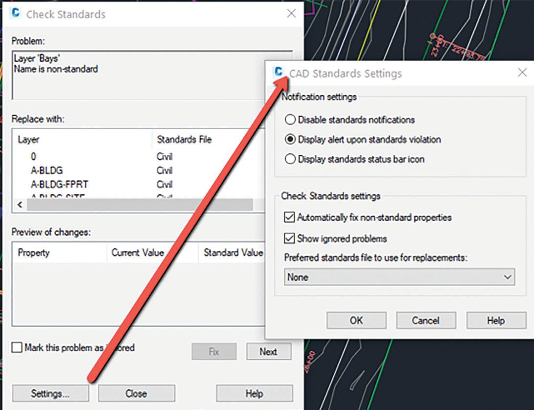
Finally, you’ll want to configure what actions happen when a standards violation is found. When
you click on the Settings button, you’ll get a dialog box where you can choose how, or if, you’d like to be notified of a violation, and what you want to do when a violation is found (Figure 4).
CHECK DRAWINGS FOR STANDARDS VIOLATION
To run a check of your drawing vs. the standards file, you can select Check Standards from the configuration editor, or you can go to the ribbon and select Check (which is just above Configure).
Doing so will display the Check Standards dialog box. It will display any problems that are found in the drawing, a suggested replacement based on what’s in the attached .dws file, as well as the options to fix the problem, ignore it, or move on to the next.
The audit checks both the named object, such as the layer or style name, and properties of that object. Choosing to fix a non-standard name will not only change the name of the object, but also purge the bad name from the drawing. If the violation should be with the property of the named object, such as the color of a layer, it will simply fix the property.
If you have not disabled notifications, you’ll see either an alert or a status bar balloon if a violation is made — or if a violation if found when opening a file that has a standards file attached Figure 5).
NOTE: AutoCAD ships with an external Batch Standards Checker that is found in the AutoCAD program group. The Batch Standards Checker does not fix problems like the internal AutoCAD tool does. Instead, it creates an XML-based report of all violations it finds in the defined drawing set.
CIVIL 3D REFERENCE TEMPLATES
You can use reference templates to manage styles, settings, layers, and other standard drawing components.
You can attach one or more reference templates to an Autodesk Civil 3D drawing so it will be updated on an ongoing basis with changes to the referenced components in the templates.
When you attach a reference template to a drawing, the referenced components (styles, settings, property sets, layers, blocks, text styles, and line types) that are in that reference template are copied into the drawing, and the connection between the drawing and the reference templates is maintained.
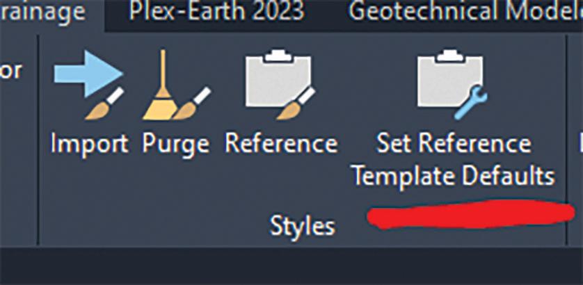
Using the Set Reference Template Defaults command, you can specify in advance which styles and settings to reference from a reference template. For example, if a template has ten-point styles, you can choose to reference only the five that you want (Figure 6).
If you do NOT see the Set Reference Template
Defaults command in your ribbon, this means you are not in a .DWT file. This command appears within the ribbon but only if your current drawing is a .DWT file. If you do not set up a reference template in advance using Set Reference Template Defaults command, you can change the selection of styles and settings that will be referenced from a template after you attach it to a drawing with the Attach Reference Template command.
You can have multiple reference templates attached to a drawing. For example, you might have templates for state, company, and project standards (Figure 7):
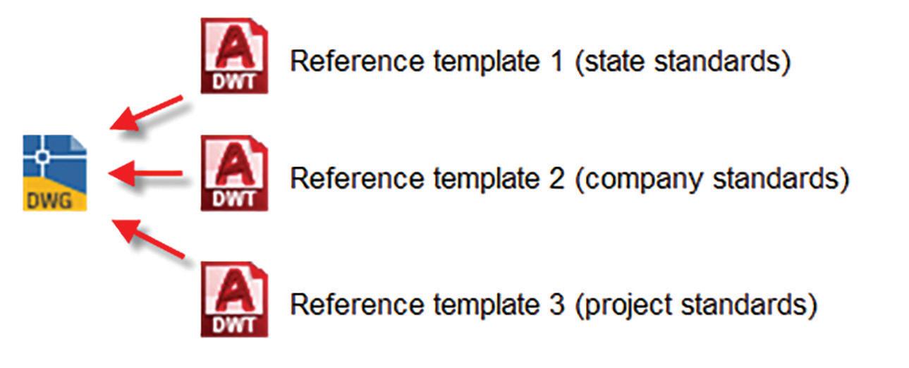
When you have attached more than one template to a drawing, you are alerted to duplicate components in the templates so you can decide how to resolve them. You can change the template priority order or choose to reference a component from a lower-priority template.
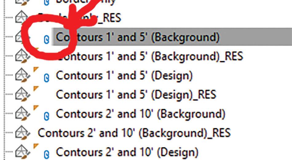
You’ll know when a style exists in your drawings that derives from a Reference Template by the sybmbol next to the style name (Figure 8).
UPDATING REFERENCED COMPONENTS
After you attach a reference template to a drawing, referenced components should be edited in the
source template rather than in the drawings to which the reference template is attached.
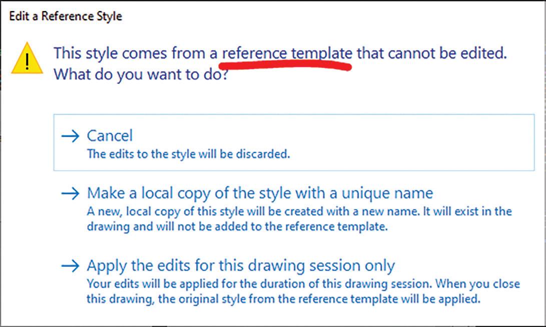
• For referenced Autodesk Civil 3D components: You are notified if you attempt to edit a referenced Autodesk Civil 3D component in a host drawing. If you try to edit a referenced style, a task dialog box is displayed with choices you can make. You can save a copy of the style, keep the changes temporarily until the drawing is reopened, or cancel the change.
• For referenced AutoCAD components: You are not notified if you attempt to edit a referenced AutoCAD component in a host drawing. If you edit a referenced AutoCAD component, the changes will be overwritten the next time the drawing is updated from the reference template (Figure 9).
At the Command line, enter AeccRefTemplateAutoUpdate.
Enter one of the following:
• 0: Turns off automatic updates. Notifications are displayed to alert you when reference template components need to be updated.
• 1: Turns on automatic updates of components from reference templates. This is the default setting.
• 2: Turns off updates of existing layers only. Existing layers in the host drawing are not updated automatically and they are not updated if you click Apply or OK in the Attach Referenced Template dialog box.
Note: When using this value, existing layers in the host drawings are not overridden by layers in the reference template. New layers that are referenced by styles or settings in the template are referenced into host drawings, but if existing layers are in the host drawings, those existing layers are not overridden.
CONCLUSION
GIS is a beast!! There is a reason why GIS users (and GIS degrees) are some of the most sought-after individuals in the marketplace right now. While there are a ton of GIS capabilities in AutoCAD, Map 3D, Civil 3D and Infraworks, they are just scratching the surface on what you can really do by utilizing GIS in your project workflows. Hopefully this helps remind you of some of those capabilities and peaks your interest on some of the more advancing technologies we will highlight coming up soon.
Thank you!
CONTROL AUTOMATIC UPDATES FROM REFERENCE TEMPLATES
Use the AeccRefTemplateAutoUpdate variable to control updates and alerts when reference templates change.
Shawn Herring has been a part of the design engineering community for roughly 15 years in all aspects of design, construction and software implementations. He has implemented and trained companies across the Country on Civil 3D and other infrastructure tools and their best practice workflows. Shawn can be reached for comments or questions at sherring@ prosoftnet.com.

Basic members have access to:
• Forums
• HotNews (last 12 months)
• AUGIWorld (last 12 months)
DUES: Free
AUGI Members Reach Higher with Expanded Benefits

AUGI is introducing three new Membership levels that will bring you more benefits than ever before. Each level will bring you more content and expertise to share with fellow members, plus provide an expanded, more interactive website, publication access, and much more!
Student members have access to:
• Forums
• HotNews (last 24 months)
• AUGIWorld (last 24 months)
• AUGI Educational Offerings
DUES: $2/month or $20/year
Professional members have access to:
• Forums
• HotNews (full access)
• AUGIWorld (full access and in print)
• AUGI Library
• ADN Standard Membership Offer
DUES: $5/month or $50/year
Are you ready to upgrade yourself and your membership? Access additional benefits and upgrade at www.augi.com
We all love getting free stuff. I especially enjoy getting free stuff that’s useful. I remember getting in the mail free sample shampoo packets to try. There was one time I even got different flavored teabags all for free in the mail. Believe it or not AutoCAD version 2.6 (which is as far as I can remember) and versions thereafter have always included free samples. The free samples I’m referring to are the many open source lisp files packaged with AutoCAD adding to the core commands and extending the power of the product. Since these free samples can be easily accessed, they can provide benefits to two groups of AutoCAD users. The first group are those who just want to use AutoCAD as a tool. This group can
benefit by knowing about and then implementing the additional commands provided by these free lisp files to help improve product efficiency. The second group are those who want to customize AutoCAD by learning how to code with AutoLISP. This group can benefit by seeing the Autodesk developers’ program. The free sample lisp files can be thoroughly examined to help improve this group’s programming skills.
MORE FREEBIES
Before I continue, I would like to illustrate how Autodesk continues to add value to AutoCAD by including more and more of these free sample lisp files.


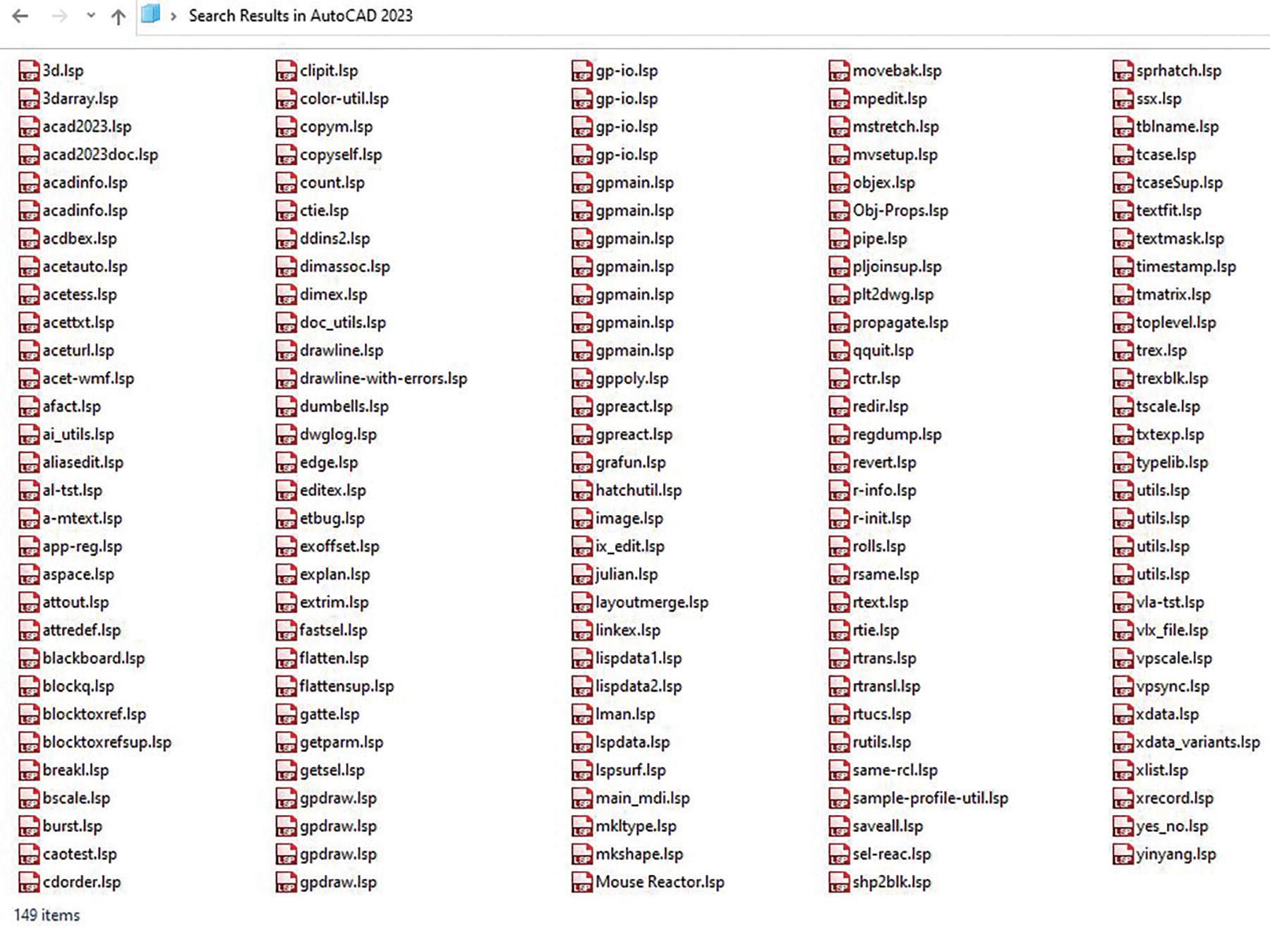
Figure 1 shows all the lisp files packaged with AutoCAD 2000 when released back in March of 1999. That version included a total of 122 free sample lisp files. Now compared that number with Figure 2 which shows all the lisp files packaged with the current AutoCAD 2023 release. The number has jumped to a total of 149 free sample lisp files.
Granted, there are some duplicate file listings. But this still clearly shows that Autodesk continues to add free sample lisp files to enhance the AutoCAD product. Now to peak everyone’s interest, I would like to introduce four of these free sample lisp commands. One of these goes as far back as AutoCAD version 2.6. But in each case, I’ll first discuss why Autodesk may have included the free lisp file. Then I’ll demonstrate the additional function the lisp file adds to AutoCAD. Finally, I’ll conclude with what came of the free sample function as AutoCAD continued development with newer releases.
ASCTEXT.LSP
ASCII stands for American Standard Code for Information Interchange. It was first published back in 1963 and had its final revision issued in 1986. In short, ASCII provided a standard for an application to generate a text file that can be successfully read by other applications. It supports 26 alphabets (A to Z uppercase and lowercase), numbers (0 to 9) and basic punctuation symbols.
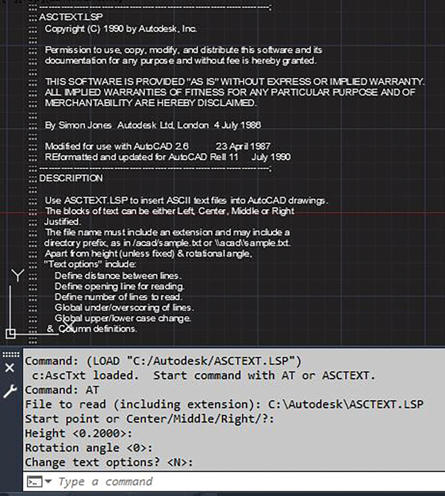
Back in April of 1987 when AutoCAD version 2.6 was released, Autodesk’s flagship graphics application was missing a command to import an external ASCII text file. Since those were still the glory days of the Microsoft Disk Operating System (DOS), there was no such thing as copy and paste or drag and drop. So, Autodesk developers probably wanted to flex their muscles to demonstrate the power of AutoLISP (introduced with AutoCAD version 2.18 in January of 1986); thus, the free sample lisp file ASCText.lsp was born (see Figure 3).
At AutoCAD’s command prompt, entering the following command sequence loads the file: (load “ASCText”)
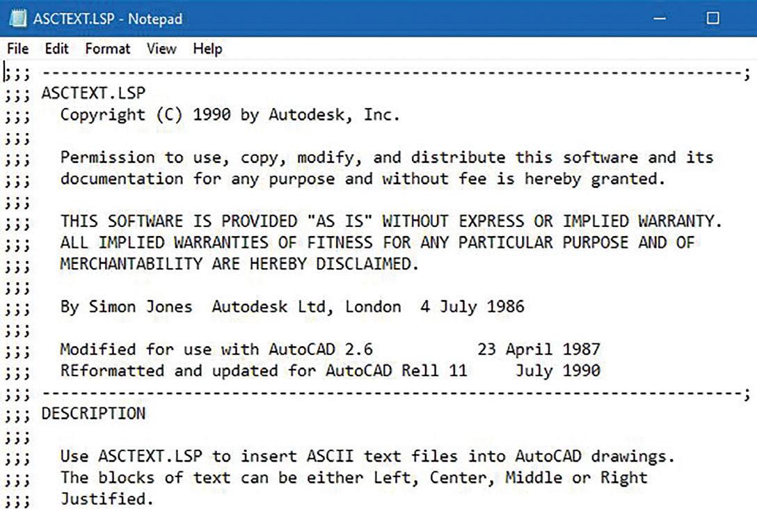
Note: This assumes that the lisp file is in the AutoCAD support search path; otherwise, the entire folder location would have to be included. Also, since the .lsp file extension is assumed, it does not have to be typed out.
After loading the code, the command prompt lists two methods for launching the added function:
• AT = shorter method for the keyboard challenged
• ASCTEXT = longer method for the exceptionally skilled typist
Then responding to the given prompts, ASCText is able to successfully import into AutoCAD the contents of a text file (in this test case even itself) into the graphics screen using lines of TEXT objects (see Figure 4).
I was also surprised to learn that this old code accepts backslashes (“\”) when a number of current lisp codes require forward slashes (“/”). Lastly, it took spaces in the folder or file name by surrounding the “File to read” entry with quotation marks (“…”).
Seven years and five releases later, the inclusion of the free sample ASCText.lsp was finally dropped in November of 1994 when Autodesk introduced in Release 13 the MTEXT command. MText added a built-in Import Text feature which can be accessed from the toolbar by clicking on the drop down arrow on the right (see Figure 5).
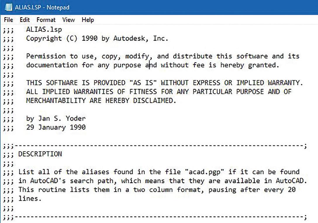

was so well watched is because viewers like myself wanted to see the lead actress Jennifer Garner kick and fight her way out of the various tough situations she encountered. Well, AutoCAD going as far back as Release 11 in 1990 had shipped with a free sample lisp file called Alias.lsp (see Figure 6).
Of course the meaning of this alias lisp file is a little bit different than the television series. AutoCAD’s alias is referring to the shortcut names found in the file Acad.pgp. Like lisp files, this pgp file (which stands for Program Parameter) is a text file that can be opened with a text editor for editing. The pgp file is divided into two sections. One section has to do with declaring commands to invoke externally in the operating system. The other section has to do with declaring aliases or shortcuts to invoke AutoCAD commands that are executed within the program (see Figure 7).

ALIAS.LSP
Back in 2001, there was a very popular television series called Alias that was broadcasted on American Broadcasting Company (ABC) for a total of five seasons. Basically this popular show was about a well trained female government agent that assumed various identities or aliases to successfully carry out her missions. I actually think the show
With the current AutoCAD version now running on Microsoft Windows Operating System, it’s easy to just launch AutoCAD and at the same time open up Notepad to edit the Acad.pgp text file. Well, back in 1990 when AutoCAD ran on DOS a user can only launch a single program at a time. There wasn’t an easy way while AutoCAD is running to launch another text editing program to know what aliases are programmed into the Acad.pgp file. In fact, back then DOS did not come with a built-in text editing program until 1994.
So here comes Alias.lsp to the rescue. At AutoCAD’s command prompt, the following command sequence loads the file: (load “Alias”)
Entering ALIAS at the command prompt executes the lisp code. Alias automatically locates the Acad.pgp file, reads the contents and displays on AutoCAD’s Text Screen listing in two columns the current aliases or shortcuts that would launch the external and AutoCAD commands (see Figure 8).
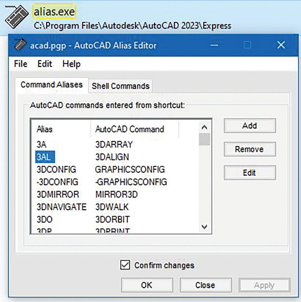
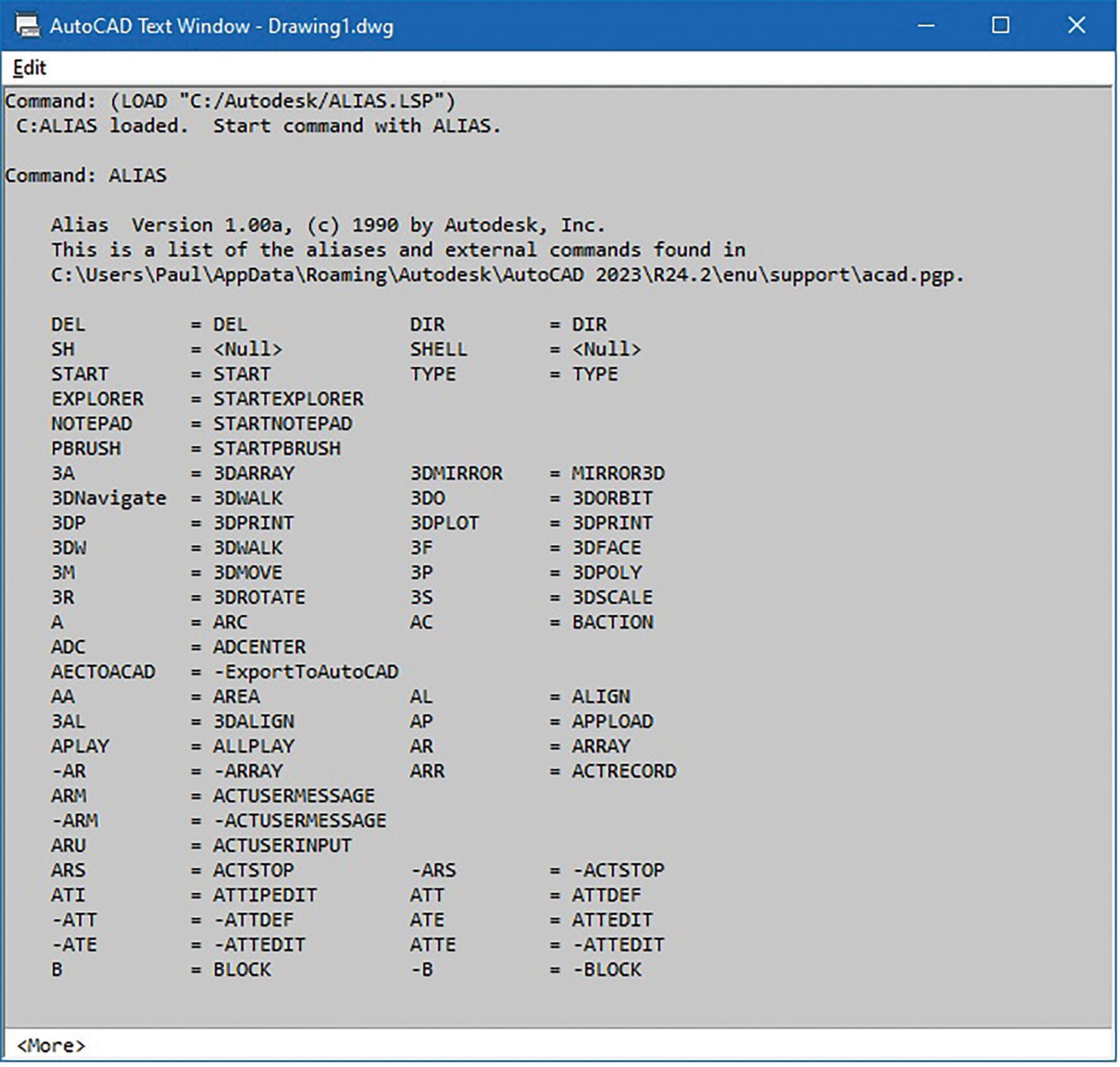
Obviously, the drawback of this initial free Alias. lsp sample code only allows the user to see the contents but does not offer an option to edit the Acad.pgp file. Eventually, Autodesk further developed Alias by converting it into an external executable (exe) file that can be launched from outside of AutoCAD starting with Release 14 in February of 1997. Now Alias.exe is part of the Express Tools package which contains add-on bonus files included for again free with AutoCAD for all subscription users. In addition to listing the aliases, users can use the upgraded Alias program to modify the shortcut commands (see Figure 9).
AXROT.LSP
My first job was at an Architectural firm in 1988 where each station had AutoCAD Release 9 installed. Though with that release thickness can be
given to objects and a two-dimensional view can be easily switched to a three-dimensional axonometric
view, there was still no option to draw on the third dimension. AutoCAD was only known for doing two-dimensional drafting. Some of us even called the program “Two and a half D”. But when AutoCAD Release 10 came out in October of 1988 all of this changed. AutoCAD introduced the User Coordinate System (UCS). The UCS provided the ability to position the two-dimensional drafting plane (X and Y axis) onto the third-dimensional plane (Z axis).
An icon was used to represent this concept. This icon can either be left on or turned off. Though this may be visibly seen on the AutoCAD graphic screen, it will not show up on printed jobs (see Figure 10).
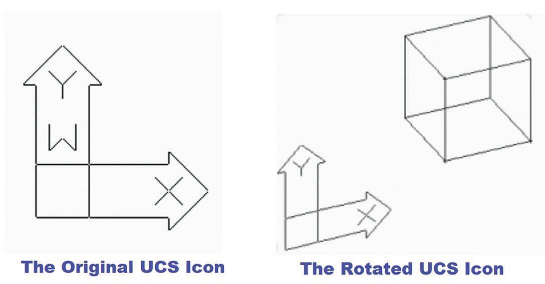
Well, this was an exceptional addition transitioning AutoCAD finally into a three-dimensional design application. But for some reason AutoCAD left out of the core product a very important command. It was missing the command to manipulate an object on all three axes (X, Y and Z).
To make up for this missing piece of the threedimensional puzzle, a version later with AutoCAD Release 11 in October of 1990, Autodesk included the free sample AxRot.lsp (see Figure 11).
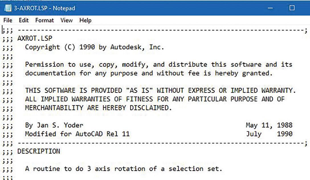
AxRot stands for Axis Rotation of selected objects. When loaded using (load “AxRot”) the program prompts for object(s) to be rotated (this can include two-dimensional and three-dimensional). Then an X, Y or Z axis is entered and finally a rotation angle along with a base point is needed to complete the command.
This free sample lisp file was dropped another version later with AutoCAD Release 12 in June of 1992 when the Rotate3D command was built into the core program. Notice how similar the prompts are when Rotate3D is executed compared to AxRot.lsp. It’s pretty clear that Autodesk
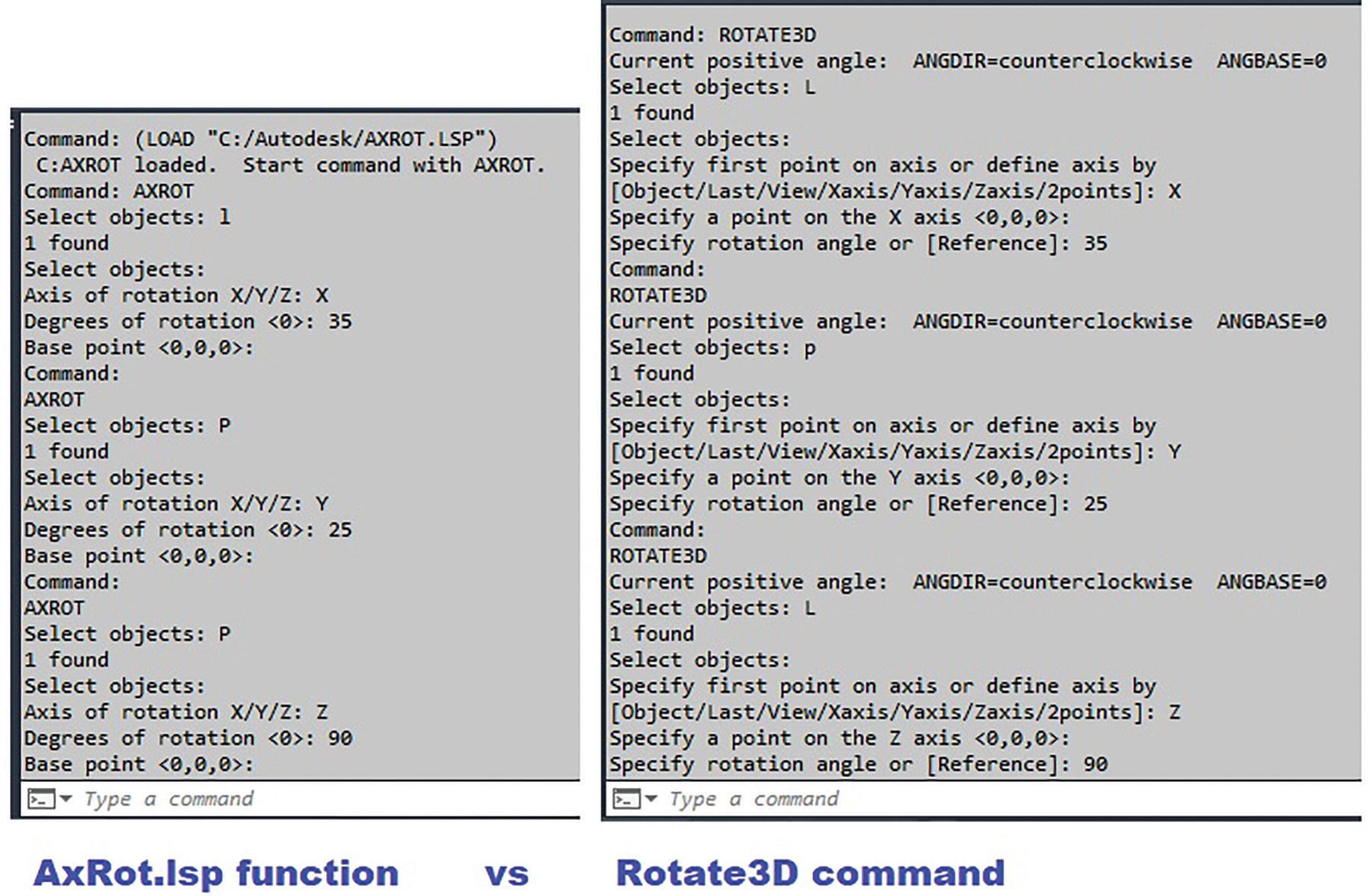
developed the Rotate3D command based on the free sample lisp file (see Figure 12).
ATTREDEF.LSP
AutoCAD version 2.0 in October of 1984 was when Attributes were first introduced. This gave users the ability to implement Block Inserts that contain Text objects that are editable called Attributes. This was absolutely necessary to make it possible for objects like Section Block symbols to appear with different editable text callouts. But, with this added feature AutoCAD forgot to include with the core product the ability to easily modify or add Attributes to existing Block Inserts.
Finally, four years and five releases later, AutoCAD Release 10 in October of 1988 included the powerful and free sample lisp file AttRedef.lsp (see Figure 13).
After loading the code using (load “AttRedef”), the command prompt lists two methods for launching the added function:
• AT = shorter method for the keyboard challenged
• ATTREDEF = longer method for the exceptionally skilled typist
Now bear in mind that back in the distant pass there was no BEdit (Block Editor) command which was not introduced till AutoCAD 2006 in March of 2005. So, to manually redefine a Block Insert with Attributes, the first thing to do is to Insert the Block exploded
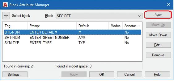
at a scale of 1. Then any of the original Attribute Definition(s) can be modified such as the Prompt and the Default Value. I would leave the Tag alone otherwise the Block Attribute value with the original Tag in all the already inserted Blocks would
be lost. At this point, new Attribute Definitions can also be added (see Figure 14).
Now running the added AttRedef command, the code prompts for an existing Block name to redefine followed by a selection of geometric as well as Attribute Definition objects. These should be selected in the exact same sequence as the original. Finally, the command concludes with requesting for the Insertion base point.
AttRedef then automatically searches the entire drawing database gathering all Block Inserts matching the given name and replacing each and every instance with changes made preserving the Attribute values already entered and adding any new Attribute Definitions. This free sample lisp file is so powerful that every release of AutoCAD from 1988 till the present 2023 version still includes it as part of the package. There is no single built-in core command that can perform this same function.
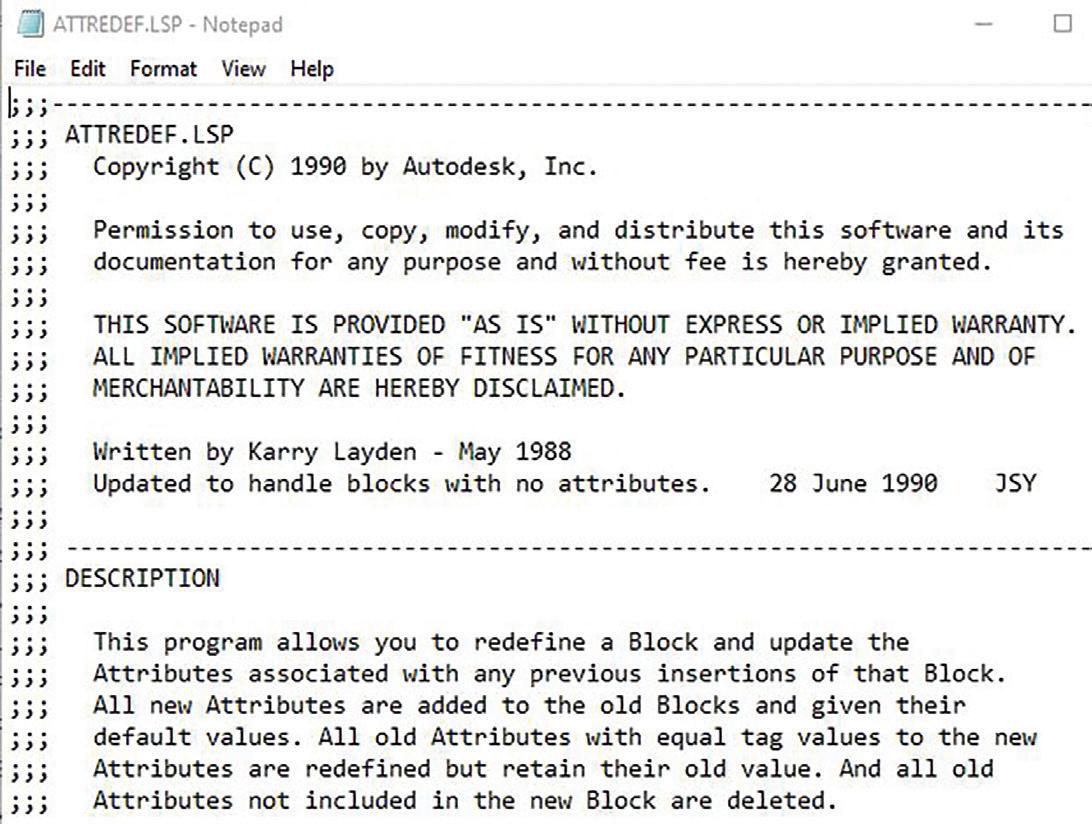
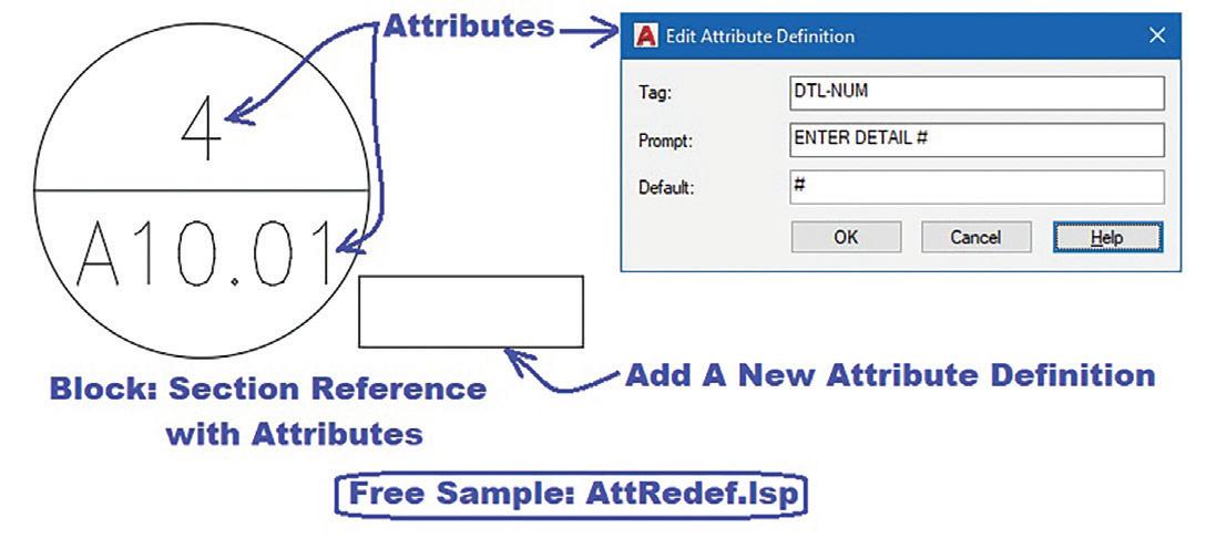
As I mentioned earlier, BEdit can partially fulfill the redefinition of the Block Insert with Attributes. But it still has to rely on a second AutoCAD built-in command called Battman. No, I’m not referring to the DC comic super hero. AutoCAD Release 2002 in June of 2001 introduced this cape crusader of a command that stands for Block Attribute Manager (see Figure 15).
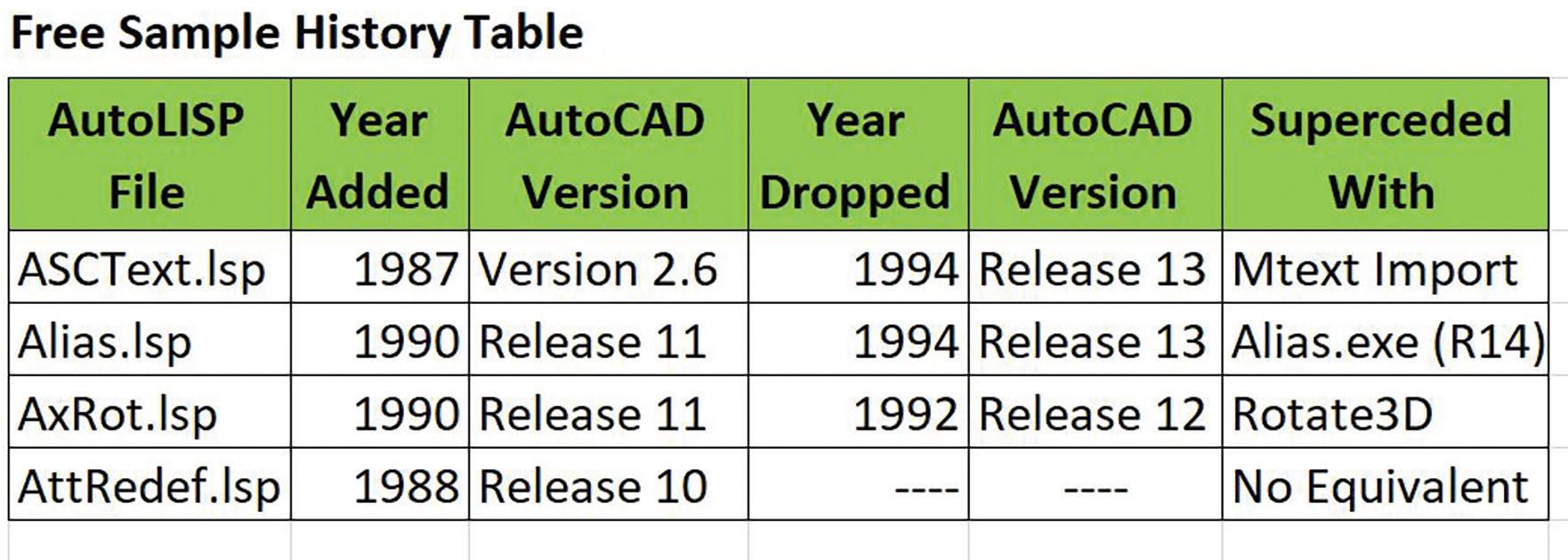
Battman offers the feature to select an existing Block Insert to modify its Attributes. But since Battman is missing the Add a new Attribute Definition function, it still has to rely on the BEdit command to perform this feat. On the other hand, changes made using BEdit does not get applied to all existing Block Inserts. So, in turn, it relies on using Battman’s Sync function to accomplish this. So that running AttRedef.lsp as demonstrated accomplishes everything in one fell swoop.
LET’S FEAST
I’ve placed in a table listing the history of all four lisp files discussed. Hopefully, I’ve got your attention on the many free sample lisp files available now and loaded with the current version of the AutoCAD program. All of these freebies once again remind me of the many free sample food stands at Costco. I remember there was one time I decided instead of going out to buy lunch I’ll just go to Costco and get my lunch from sampling each and every food stand. So, it’s time to go and crack open the AutoCAD folder and feast on the many free gems hidden within.
Mr. Paul Li graduated in 1988 from the University of Southern California with a Bachelor of Architecture degree. He worked in the Architectural field for small to midsize global firms for over 33 years. Throughout his tenure in Architecture he has mastered the use and customization of AutoCAD. Using AutoLISP/ Visual Lisp combined with Dialog Control Language (DCL) programming he has developed a number of Apps that enhance the effectiveness of AutoCAD in his profession. All the Apps actually came out of meeting challenging needs that occurred while he worked in the various offices. He has made all the Apps available for free and can be downloaded from the Autodesk App Store. Though he recently retired from the Architectural profession, Paul continues to write articles depicting his past work experience. Some of these articles can be found in AUGIWorld Magazine where he shares his knowledge learned. Paul can be reached for comments or questions at PaulLi_apa@hotmail.com.

Bright Ideas for a Bright Future
AUGIWORLD brings you the latest tips & tricks, tutorials, and other technical information to keep you on the leading edge of a bright future.

