


ARCHITECTURE INTERNSHIP PORTFOLIO
1.
- 1RW19AT020
- Atul Shivakumar
RV COLLEGE OF ARCHITECTURE
 Ar. Dean D, Cruz Founder and Principal Architect

“We love the creative process that goes into design, the burst of insight and energy represented as confetti in our logo.”
After graduating from Sir J.J. College of Architecture, Bombay, in 1983, Ar. Dean joined architect Gerard Da Cunha as an assistant in Goa in 1985. Enamoured by the soft and human scale of Goa’s Architecture and lifestyle he decided to stay. In 1986, he became a partner in afirm called Natural Architecture, working on cost effective housing in a very Laurie BakerVV approach using waste building materials and innovative design.
In 1994 he expanded base of design work, taking on small hotels, large houses and institutional work as principal architectof Dean D’Cruz & Associates.
Mozaic was set up in 2001, co-founded with Reboni Saha where Ar. Dean heads the architectural wing, integrating different design approaches to provide holistic services.
As of today, he has designed over 250 houses, 50 hotels, 30 housing complexes, 30 institutions, offices and factories, Ar. Dean D’Cruz is recipient of multiple awards. His strength today is in the hospitality industry, from boutique hotels and jungle lodges to 200+ room resorts. His current efforts are aimed at improving academic standards across the country through awareness of criteria that address environmental and social issues in architecture and planning; all made possible through workshops, master classes and his presence as a jury member on a large number of award platforms.
2.
ACKNOWLEDGMENT
I extend my sincere gratitude to Principal Architect Dean D’Cruz for the invaluable experience and opportunity offerded to me at Mozaic Design. Your mentorship has been instrumental in shaping my understanding of architecture and refining my skills.
Further, I would like to extend my gratitude to Ar. Claudio Da Silva Teles, Ar, Sunaina, Ar. Rahul G. and all the support staff present at the firm for their unwavering help extended at my tenure here.
The commitment to excellence and innovative thinking that Mozaic strive for has inspired me to push the boundaries of creativity in my work. I am truly appreciative of the trust you placed in me and the support provided throughout my journey.
This tenure for me, has not only been enriching professionally but also personally rewarding.
I am grateful for the encouragement and wisdom you imparted, which have undoubtedly contributed to my growth as an architect. Thank you, Principal Architect D’Cruz, for your guidance, leadership, and for instilling in me a passion for excellence in architecture.
3.
Ar. Dean D, Cruz
Principal Architect
Ar. Claudio
Architect In-charge
CLUBHOUSE INVERNESS
AHMEDABAD, INDIA
3.
4. 5.
MISCELLANEOUS GOA STUDY REPORTS
FISHTAIL CREEK, KARWAR CATHEDRAL MATERIAL STUDY
6.
SITE VISITS
4.
CONTENTS 1. 2.
CARMONA VILLAS
CARMONA, GOA
REVORA HOUSE
REVORA, GOA
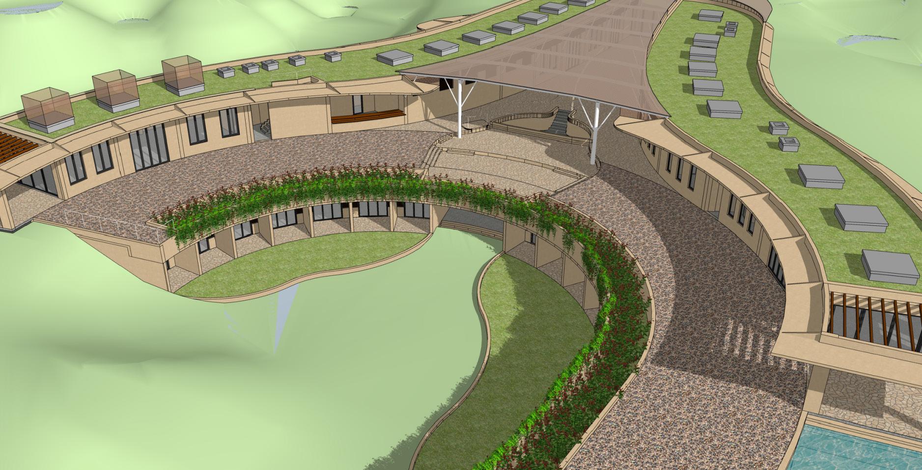
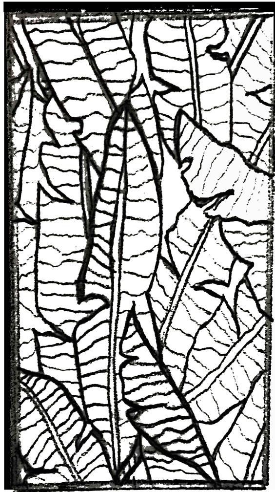
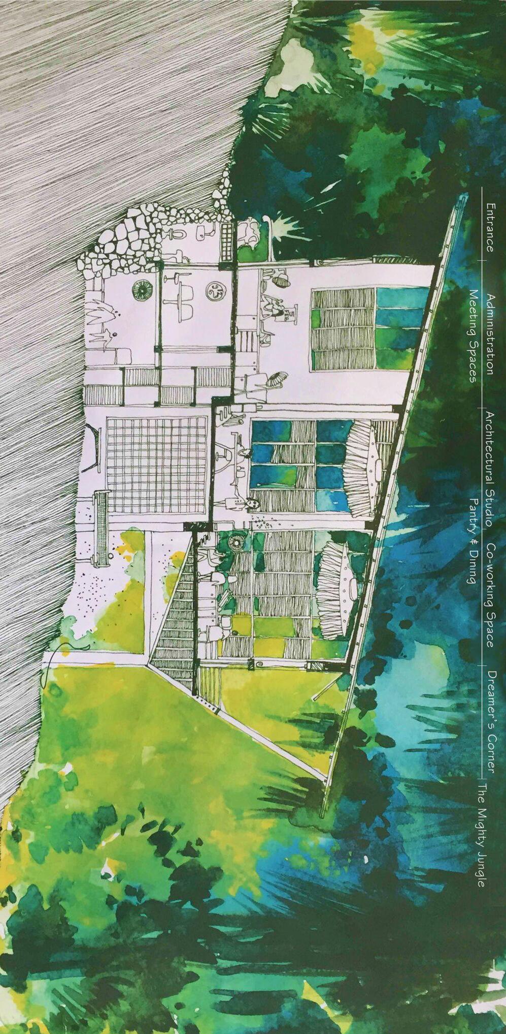
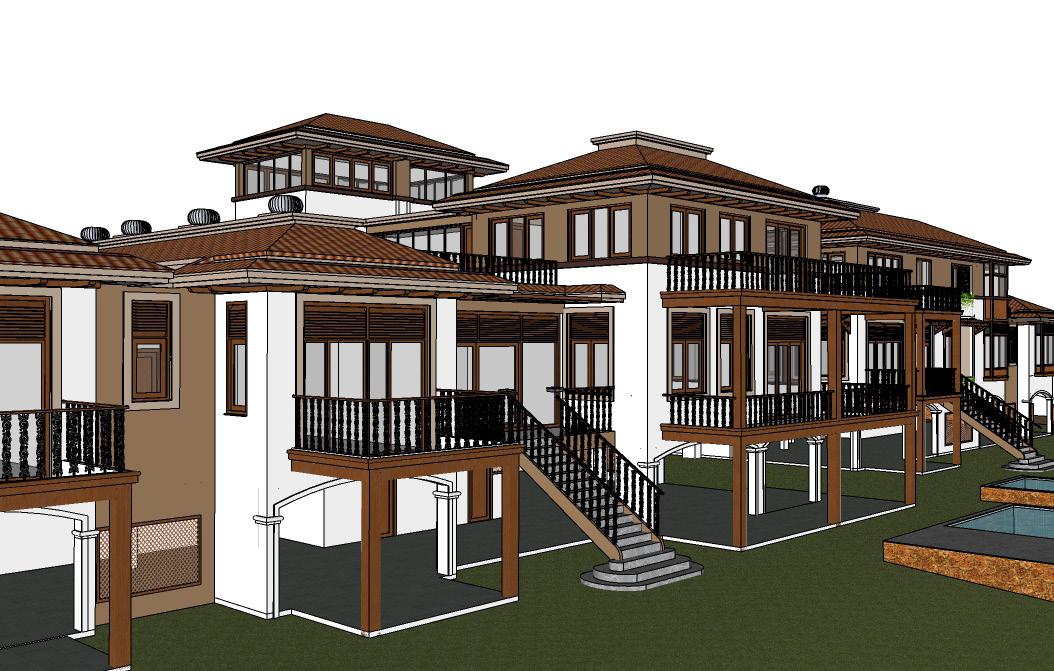
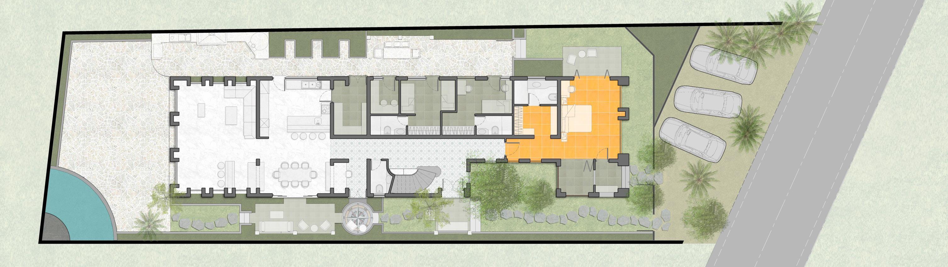
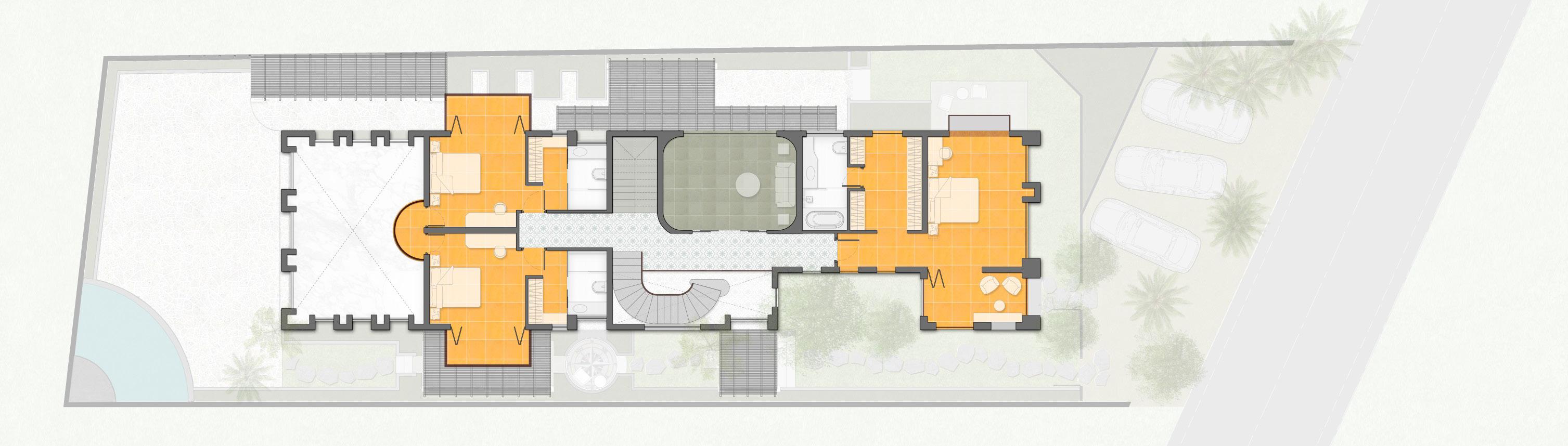
Clubhouse Aalloa hills Ahmedabad, India
A luxurious commercial multi-purpose space intended as a clubhouse in the Aalloa Hills residential project currently underway in Ahmedabad, India.
Morrocon themed architecture read across the facades and the intricate interiors.
5.

6. 7 9 DN N A A 1 A 2 A A A 5 A 6 A A A A 0 A N 1 N 16 N 15 N 4 N 7 N 6 N 15 N 1 N 0 R A N.A A1 A2 A3 A4 A5 A6 A7 A8 A9 A10 A0 N17 N16 N15 N14 N17 N16 N15 N14 N 0 N1 N2 N3 N4 N5 N6 N8 N9 N10 N11 N12 N13 N7 NB NA NB N 1 N 2 N 3 N 4 N 5 N N 8 N 9 N 10 N 1 N 1 N 1 N N B N A N B N F 5 F 0 F L + 0 U L ± 0 F 50 F 00 F 05 UF 0 F 0 F - 0 F 38 U - 0 F 50 F 00 F L + 0 U L 0 F 50 F 00 F 50 F 00 F 0 F 0 F 05 U 00 F 40 U - 0 F 8 F - 0 F - 0 F - 0 F - 05 F - 06 F L - 00 U - 60 46 71 12 61 73 14 91 1 1 2 3 2 80 30 5 1 69 3 56 3 9 24 8 7 67 06 67 2 11 7 3 0 10 5 4 4190 11 3150 800 418 3 34 417 18 2 3 1 1 4 8 0 32 5 2 1 5 2 EQ EQ EQ 4 4 1500 Q 1 4 4 EQ Q 4 61 Q EQ 15 06 06 6 7 0 8 Q EQ 3 47 21 0 3 1 4 13 63 437 4 2 EQ Q 887 9 509 756 766 766 1 41 485 69 485 122 1227 876 501 501 876 1161 912 912 1343 948 624 624 030 APA APA APA 74 474 APA APA 447 447 APA 485 26 1 2664 12 791 713 16 415 190 1165 6116 715 1132 4870 48 8 977 1639 558 3555 192 1500 1005 1005 1517 756 509 509 7 18 463 63 63 169 13 43 43 8 1 7216 644 750 845 470 0 8 8724 798 423 423 98 790 415 415 790 1441 6278 6001250 1115 6122 5001860 500 152 1627 600 1238 1315 1012 2169 9001012 12501000 10001365 2848 350 350 16501015 15391424 465 1000 1000 350 968 600 1365 1238 1442 5157 437 773 761 404 192 3115 3115 1586 4952 3230 212 758 750 474 886 509 1475 1490 702 1402 696 15 EQ EQ 750 375 375 E EQ 1 992 15 4 50 550 1450 1 0 00 360 EQ EQ 150 EQ EQ 37 5 EQ EQ APA APA 2483 2427 7 7 EQ EQ 7 EQ EQ 150 1453 EQ EQ EQ EQ 750 Restauran 16650 X 8000 To le s S aff Toi ets Serv ce Lobby Interact ve Ki chen Ki chen 15250 x 9850 Banquet Serv ce Bay Banque Ha 21450 X 9950 Secur ty Room Pool Deck Ca e 18800x 9200 Gents To ets Lad es To le s Pantry Ca e Service Area Board Room 4800 X 9900 Gents Toi ets Ladies Toi ets Recep ion Server Room HR Office F 0 U L - 50 F 8 F - 0 F L 0 UF - 6 F L 0 UF - 60 F 03 U L - 0 UF 0 R 87 RL 87 30 RL 87 30 RL 89 8 SLOPE 1:11 RL 87 30 RL 87 30 RL 87 30 RL 87.30 RL 87 30 PARKING UNDER REVIEW N E N D N C R 8 22/02/2024 SCALE 1:300 @ A3
7. P va e Landscape o Rooms As pe Landscape Des gn FOYER 8900 x 6800 T 3 0 R 16 6 1-R1 R1 R1 R1 R1 R1 R1 R1 R1 R1 R1 R1---------------------------------------------------------N E N D N C N A R 8 N1 N2 N3 N4 N5 N6 N8 N9 N10 N11 N12 N13 N7 NB NA NB N N N N N 5 N 6 N N 9 N 0 N 1 N 2 N 3 N N B N A N B N 0 RL 83 20 RL 82 20 RL 83.20 A A A A A A 7 A 8 A A 10 A 0 N 17 N 16 N 1 N 14 N 1 N 1 N 1 N 14 N 0 R A A0 N17 N16 N15 N14 N17 N16 N15 N14 N A 3 A4 A5 A6 A7 A8 A9 A10 A.2
SCALE 1:300 @ A3
22/02/2024
22/02/2024
8. 9 DN F 50 F 50 F 0 F 50 F 50 F 5 F L + 4 U 0 F 50 F 15 F 5 F 5 F L + 4 U L 4 F 25 U 15 N A A 1 A 2 A A A 5 A 6 A A 8 A A 10 A N 1 N 16 N 5 N 14 N 7 N 6 N 15 N 1 N R A N.A A1 A2 A3 A4 A5 A6 A7 A8 A9 A10 A0 N17 N16 N15 N14 N17 N16 N15 N14 N 0 N1 N2 N3 N4 N5 N6 N8 N9 N10 N11 N12 N13 N7 NB NA NB N 1 N 2 N 3 N 4 N N N 8 N 9 N 10 N 1 N 1 N 1 N 7 N B N A N B N
SCALE 1:300 @ A3
TERRACE
9. UFL 0.00 Landing N.E N.D N.C 5000 5000 5000 5000 5000 5000 5000 5000 1220 Wide Lexan Sheet with RHS supporting Grid as Slender possible CHS Strucutral support CHS Strucutral support Slender as Possible CHS Strucutral support CHS Strucutral support as Slender as Possible 5158 RAILING AS PER DETAIL 600 3400 600 3400 600 3400 600 3400 600 3400 MS GRILL DOOR TO BE DESIGNED WATER PROOFING VERANDAH ROOM TOILET 3500 2610 PASSAGE PLANTER BED Services 2650 PER LANDSCAPE 600 DROP FOR LANDSCAPE Note: Pool Depth may increase by 150, as per Pool Vendor Services, Skimmers to be incorporated into Design N.E N.D N.C S.A S.B 3500 1500 5000 1450 ADJACENT LVL Note: Proposal for Edge and Compound Detail near Pool Side to reduce Retaining Amount 25/02/2024 SCALE 1:300 @ A3 SECTION II’ SECTION AA’ SECTION BB’ SECTION CC’ SECTION DD’ SECTION EE’ SECTION GG’ SECTION HH’
10. ARRIVAL COURT SERVICE ROAD DROP OFF POINT 0 81.50 N-2583014.892 E -265502.992 Z -87.170 GWR 3 29/02/2024 SCALE 1:500 @ A3
11. FFL +0050 UFL +0000 FFL +0050 UFL +0000 FFL +0050 UFL +0000 FFL +0050 UFL +0000 FFL +0050 UFL +0000 FFL +0050 UFL +0000 FFL +0050 UFL +0000 FFL +0050 UFL +0000 FFL +0050 UFL +0000 FFL +0050 UFL +0000 FFL +0050 UFL +0000 FFL +0050 UFL +0000 FFL +0050 UFL +0000 FFL +0050 UFL +0000 FFL+005 UF 0000 FFL 0050 UFL+ 000 FFL 0050 UFL+0000 FFL 0050 UFL+0000 FFL+0050UFL+0000 FFL+0050UFL+0000 FFL+0050UFL+0000 FF +0050 UFL+00 0 FFL 0050 UF 0000 FFL 0050 UF 0000 FFL+005 UFL 0000 FFL+00 0 UFL 0000 FFL+0 50 U L +000 A 1 A 2 A 3 A 4 A A 6 A A 8 A 9 A 0 A N 17 N 6 N 15 N 4 N 1 N 6 N 1 N 4 N A1 A2 A3 A4 A5 A6 A7 A8 A9 A10 A0 N17 N16 N15 N14 N17 N16 N15 N14 N 0 000 500 00 500 0 500 0 500 0 500 16280 500 0 500 0 500 120 12 0 1 3 0 160 230 9 10 9740 91 5 761 4 65 N1 N2 N3 N4 N5 N6 N8 N9 N10 N11 N12 N13 N7 NB NA NB N.1 N.2 N.3 N.4 N.5 N.6 N.8 N.9 N.10 N.11 N.12 N.13 N.7 N.B N.A N.B N.0 0 00 0 1 0 0 1 0 1 0 0 0 0 05 70 99 0 838 0 6 4 5 7 3 3 5 340 0 0 0 11 0 120 125 125 125 340 1175 11540 8670 6 40 5495 4 80 3870 3295 28 5 2500 235 130 1 00 50 203 7665 134 18/03/2024 SCALE 1:300 @ A3 N
TYPICAL ROOM R1 & R2 DIMENSIONS
12. F50 U L1401 0 FL4 0 U L41 0 F L40 0 UF4 0 F4 0 U4 0 FF50 U -4100UFL - 0 -4100 -4050UFL-41 FFL0 UFL10 F L4 5 FL4 00 FF4 05 U L01 N.E N.D N.C 00 0 35 20 00 0 20 3 5 F L05 FL4 0 F -0 0 196 240 21 80 2 2 0 19 PB 4 L PB2 L B B L B L B LPB2 LPB2 LPB2 LPB2 LPB2 LPB2 LPB2 LPB2 PB 2 L B 2 L PB L P 2 L P B 2 LP 2 LP 2 LPB2 LPB2 LPB LPB2 LPB2 LPB2 L B LPB2 PB L B LPB1 LPB1 LPB1 LPB1 LPB P LPB1 LPB1 LPB1 LPB 1 L PB 1 LPB 1 LP 4 N.E N.D N.C N.A 500 N A N.A R A 15075 2590 6055 2300 5 075 0 42 23 0 55 2 0 83 32 3 62 109 5 386 518 9 7345 98 5 0820 36 97 130 960 143 0 25 9 60 55 00 2 0 60 5 23 00 25 90 6 55 23 0 25 90 350 00 500 0 500 0 500 5 0 500 5 0 2 00
SCALE 1:300 @ A3 N
18/03/2024
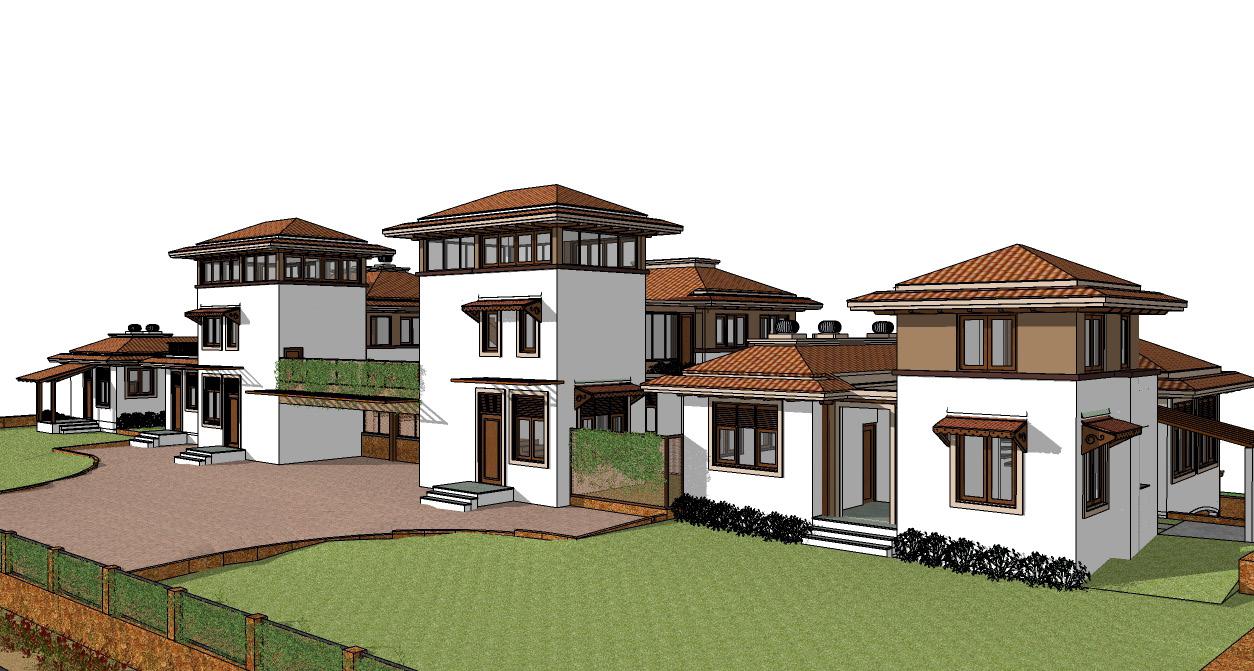
A beautiful, extravagant twin villa designed along open paddy fields in Carmona. Two families have the sanctity of one’s own home with a sense of liberty with vast common, shared spaces.
13.
Rajesh & B.N Sharma Carmona, goa
14. ARCHITECT: OWNER: DATE: MOZAIC 1 DESIGN VALLEY, ALTO-PORVORIM, BARDEZ- GOA 403521 TEL: (+91) 832 2410471 2 FAX: (+91) 832 2412570 Em: architecture@mozaic.in url www.mozaic.in DEAN D'CRUZ CA / 1985 / 09242 MR. RAJESH KUMAR SINGH & MR. BADRI NARAYAN SHARMA 01/04/2024 PROJECT: PROPOSED RESIDENCES ON PLOT BEARING SURVEY NO. 72/ 12-H, CARMONA VILLAGE, SALCETE TALUKA, GOA D1 W10 W2 W3a W3a W10 D8 W6 SD1 W5 W1a W1a W11 TOP GROUND LVL PLINTH LEVEL ±0.00 m -0.60 m GROUND FLOOR LINTEL LEVEL +3.00 m PLINTH LEVEL ±0.00 m SPRINGING LEVEL +3.75 m TOP GROUND LVL -0.60 m 0.6 3 5 W2a W2b V3 V3 D7 RIDGE LEVEL +5.09 m GROUND FLOOR LINTEL LEVEL +3.00 m SPRINGING LEVEL +3.75 m RIDGE LEVEL +4.85 m W2 V5 W12 SD2 HOUSE FOR RAJESH SINGH HOUSE FOR BN SHARMA EP EP EP TBM -1 50.00 N PROPOSAL FOR FUTURE 15m X 7m VILLA PROPOSAL FOR FUTURE 15m X 7m VILLA POOL PUMP ROOM UNIT 2 UNIT 1 I.C. I.C. I.C. I.C. I.C. I.C. I.C. I.C. I.C. I.C. I.C. I.C. ST SP ST SP HOLY CROSS CHAPEL- GAVON CARMONA RD ST SEBASTIAN'S CHAPEL RR7 TRAVELS SURVEY NO 72/12-H, CARMONA VILLAGE, SALCETE TALUKA SOUTH GOA ST SEBASTIAN'S CHAPEL RD OUTLET INLET GL OPENING 20 x 20 L1 L2 b 0.50 0.30 0.60 0.20 h1 h e PLAN OF SEPTIC TANK SECTION A-A A' B' B SECTION B-B' 1:3:6 P.C.C RUBBLE PACKING OUTLET G.L (20 X 20) SLOPE 1:25 INLET INSPECTION COVER 20 THK SLOPE 1:15 OPENING G.L VENT PIPE A SAND RUBBLE CHARCOAL POWDER RUBBLE CRUSHED TILES TIMBER PLANK d h1 0.60 h SOAK PIT 0.30 0.20 SOAK PIT d d SEPTIC TANK'S DIMENSIONS FOR 50 USERS h1 e L2 L1 d h b 1.20 2.40 1.20 1.80 2.15 1.40 0.10 0.20 LATERITE WALL GL W2 D7c OPEN TERRACE D7 D7a D6 D6 D6a W4 D6 W3a W11 V1 OUTDOOR SHOWER V4 PLINTH LEVEL ±0.00 m LOWER GROUND LVL -2.75 m STILT FLOOR FLOOR LEVEL -2.65 m V1 V1 W4b STILT AREA STILT AREA STILT AREA STILT AREA STILT AREA STILT AREA STILT AREA GROUND FLOOR LINTEL LEVEL +3.00 m PLINTH LEVEL ±0.00 m SPRINGING LEVEL +3.75 m RIDGE LEVEL +4.85 m LOWER GROUND LVL -2.75 m STILT FLOOR FLOOR LEVEL 2.75 5 2.75 D11 V5 V5 RIDGE LEVEL 2 GROUND FLOOR LINTEL LEVEL +3.00 m SPRINGING LEVEL +3.75 m +5.09 m 5 D7b W1c W1b STILT AREA SD1 D6 V5a V5a PERMISSIBLE FLOOR AREA CALCULATION A [B or C, whichever is less] FAR Effective plot area 25% of (A) F.A.R R/W area Permissible floor area 433.50 1734 1734 AREA STATEMENT 13 G.F. Built Up EFFECTIVE COVERED AREA FOR GROUND COVERAGE CALCULATIONS Total Effective covered area Coverege % Total Effective covered area 100 eff. plot area Zone Total plot area (sqm) F.A.R permissible Covered permissible 2 6 5 7 Covered area permissible Areas (sqm) 40% effective plot area Length of compound wall = 150.97 mt. Main gate opening = 5 mt. Total 8 Ground floor F.A.R. 12 First floor Built Up Area Deductions Floor Area Level F.A.R B.U.A.- Deductions 382.09 30.70 158.68 19.78 350.76 138.90 1409.26 60 2890 44.81 865.16 29.93% 40% 1156 1 VP2 R/W area (sqm) 3 Net effective area for plot (sqm) 42890 A B C UNIT 1 Second floor 29.99 29.99 1295.26 114.00 9 Ground floor First floor 258.55 5.18 103.13 253.37 97.95 Second floor 10 Ground floor First floor 112.26 3.45 126.15 23.13 108.81 103.02 UNIT 2 UNIT 3 11 Ground floor First floor UNIT 4 112.26 3.45 126.15 23.13 108.81 103.02 Total Floor area 100 eff. plot area 5.18 0 1 LOCATION PLAN SCALE: NTS N 2 SITE PLAN SCALE: 1:200 N 3 SEPTIC TANK DETAILS SCALE: 1:50 4 ELEVATION 1A-1B SCALE: 1:100 5 ELEVATION 2A-2B SCALE: 1:100
15. ARCHITECT: OWNER: DATE: MOZAIC 1 DESIGN VALLEY, ALTO-PORVORIM, BARDEZ- GOA 403521 TEL: (+91) 832 2410471 2 FAX: (+91) 832 2412570 Em: architecture@mozaic.in url www.mozaic.in DEAN D'CRUZ CA 1985 / 09242 MR. RAJESH KUMAR SINGH & MR. BADRI NARAYAN SHARMA 01/04/2024 PROJECT: PROPOSED RESIDENCES ON PLOT BEARING SURVEY NO. 72/ 12-H, CARMONA VILLAGE, SALCETE TALUKA, GOA PWDR 1.0 2.6 LIVING ROOM 8.0 X 6.0 BEDROOM 4.0 5.6 BEDROOM 1 4 X 5.5 STORAGE 2.5 X 2.4 KITCHEN 4 X LOBBY 3.75 X 3.85 LIFT DINING 5.8 X 4.4 W1 W1a W1a V1 W1a D3 D4 D3 D3 D3 D3 D2 D3 D7 SD1 D6 D6 SD2 V1 W3 D4 D5 STAFF ROOM X 2.9 SERVICE VERANDAH 2.5 X 2.9 D8 W8 DECK 3.46 2.4 DECK 9.3 X 2.4 HOME THEATRE 5.5 X 6.0 CAR PARKING 9400 4080 D4 W1a W2b W1a W1 W1 D3 V2 D7 D1 D5 D2 V1 V1 BEDROOM 3.6 X 5.8 BEDROOM 1 3.6 X 4.5 UTILITY 1.7 X 3.6 KITCHEN 5.4 3.6 LOBBY 3.75 X 3.85 LIVING 7.0 X 5.8 DINING 4.0 X 4.1 DECK 3.46 2.4 W8 W6 W7 W5 SD2 SD1 DECK 3.46 X 2.4 1m PASSAGE DRESS BALCONY 5.8 X 1.9 VERANDAH 4.4 1.3 C2 C7 C10 C15 C22 C1 C3 C8 C11 C4 C5 C14 C18 C21 C25 C28 C31 C30 C33 C32 C29 C26 C27 C24 C20 C23 C19 C16 C12 C13 C17 C9 C6 BATHROOM 2.1 X 2.2 BATHROOM 2.9 2.7 TOILET 2.3 1.25 T 275 R = 175 BATHROOM 2.9 2.45 D4 DRESS E E' A1' A1 2B 3 1B 2A 6 1A A' A D D' D10 V6 1m PASSAGE FOUNTAIN 275 175 V2 W4a D6 DECK DRESS 2.2 X 1.6 6.69 3.46 2.4 4.06 2.32 7.54 6.96 5.26 6.29 9.26 4.46 9.36 5.75 5.5 6.16 2.5 4.46 4.46 5.49 5.86 11.42 6.96 6.4 2.5 6.11 3.96 2.7 4.83 9.4 5.91 13.34 10.86 912 716 700 OVEN 600X 600 DISH DRYER WASH W2 D4 BEDROOM 2A 2.8 X 5.0 DRESSER 2.9 X 2.5 D7 W2 W2 V6 V5 W2 W2 W1 9.15 D7b D3 W4a W1c W10 D1 W12 V2 SD3 SD4 W8a C30 C26 C21 C22 C27 C31 C34 C35 C36 C29 C24 C23 C28 C7 C1 C2 C8 A 34.53 sqm. B 20.86 sqm. C 18.28 sqm. D 93.39 sqm. E 3.12 sqm. 1 5.18 sqm. F 14.02 sqm. G 49.89 sqm. H 9.74 sqm. 9.50 sqm. J 29.99 sqm. K 48.02 sqm. L 54.65 sqm. 2 7.86 sqm. 3 11.92 sqm. M 9.47 sqm. N 16.48 sqm. O 29.64 sqm. P 66.54 sqm. Q 3.73 sqm. 4 5.46 sqm. R 31.08 sqm. S 21.54 sqm. T 9.20 sqm. U 27.22 sqm. 5 5.46 sqm. V 3.73 sqm. 6.03 3.46 3.23 10.87 3.46 6.96 2.21 7.54 5.49 6.29 3.23 3.23 11.69 12.29 5.93 1.59 9.55 8.46 7.86 6.03 6.96 1.45 11.41 4.35 3.65 4.46 14.92 2.5 4.46 4.83 3.41 4.44 3.65 AREA SQ.M. BLOCK A DEDUCTIONS BUILT-UP AREA (GROUND FLR) B C TOTAL 34.53 20.86 18.28 640.5 FLOOR AREA NET TOTAL BUILT-UP AREA DEDUCTIONS 640.5 35.88 604.62 35.88 D 93.39 E F 14.02 G 49.89 5 TOTAL H K L M 54.65 9.47 5.46 3.12 9.74 9.50 29.99 48.02 N 16.48 O 29.64 P 66.54 Q 3.73 R 31.08 S 21.54 T 9.20 U 27.22 2 5.18 7.86 V 3.73 3 4 11.92 5.46 5 5.46 2 5.18 7.86 3 4 11.92 5.46 D8 GROUND FLOOR LINTEL LEVEL +3.00 m PLINTH LEVEL ±0.00 m SPRINGING LEVEL +3.75 m +5.09 m TOP GROUND LVL RIDGE LEVEL 2 -0.60 m GROUND FLOOR LINTEL LEVEL +3.00 m PLINTH LEVEL ±0.00 m SPRINGING LEVEL +3.75 m RIDGE LEVEL1 +4.61 m LOWER GROUND LVL -2.75 m STILT FLOOR FLOOR LEVEL -2.65 m STILT AREA 3 1 2.75 5 W3 W3 W3a W11 V4a V6 D3c 0.45 WALL (0.25M THK.) 0.4M 0.4M LATERITE PIER AT 3.0MC/C A PLAN OF FRONT COMPOUND WALL AND GATE A' 1.50 PART ELEVATION OF FRONT COMPOUND WALL AND GATE SECTION A-A' M.S. SWING GATE (0.50M 0.10M) LATERITE COMPOUND WALL (0.25M THK.) 3.90 0.50 0.50 0.45 1.5m SECTION B-B' 1.20 0.30 1.50 B B' LATERITE COMPOUND WALL (0.25M THK.) GRILL GRILL PLAN OF SIDE COMPOUND WALL PART ELEVATION OF SIDE COMPOUND WALL M.S. SWING GATE 2.00 2.00 2 GROUND FLOOR PLAN SCALE: 1:100 GROUND FLOOR AREA DIAGRAM SCALE: 1:100 N COMPOUND WALL DETAILS SCALE: 1:100 1 ELEVATION 6 SCALE: 1:100


16. ARCHITECT: OWNER: DATE: MOZAIC 1 DESIGN VALLEY, ALTO-PORVORIM, BARDEZ- GOA 403521 TEL: (+91) 832 2410471 2 FAX: (+91) 832 2412570 Em: architecture@mozaic.in url www.mozaic.in DEAN D'CRUZ CA / 1985 / 09242 MR. RAJESH KUMAR SINGH & MR. BADRI NARAYAN SHARMA 01/04/2024 PROJECT: PROPOSED RESIDENCES ON PLOT BEARING SURVEY NO. 72/ 12-H, CARMONA VILLAGE, SALCETE TALUKA, GOA POOJA 2.18 X 2.85 W1b W1b W3a W3a W5 D7a D3a W3a MASTER BEDROOM 4.5 X 6.0 SD3 W6 BALCONY 2.4 9.3 D4a D4a TOILET 3.0 1.8 DRESSER 5.5 X 3.5 STEAM TOILET 2.6 1.8 PASSAGE 1.2m W LIFT T 275 R 175 D14 SLOPE SLOPE SLOPE SLOPE SLOPE SLOPE SLOPE SLOPE 5 D3a PANTRY 4 TERRACE 5.8 4.4 TERRACE TERRACE DECK 9.4 X 3.85 C30 C26 C21 C22 C27 C31 C34 C35 C36 C29 C24 C23 C28 C7 C1 C2 C8 3.85 0.23 3.46 6.96 4.31 3.08 1.2 6.03 2.25 0.53 4 1.03 1 9.36 2.4 5.75 1.5 4.05 3 11.59 EQ EQ BALCONY 3.46X 2.4 SLOPE SLOPE SLOPE SLOPE SLOPE SLOPE PLANTER BOX C2 C7 C10 C3 C8 C11 C4 C5 C14 C18 C21 C25 C24 C20 C19 C16 C12 C13 C17 SLOPE 275 175 TERRACE 7.3 X 5.2 PROPOSAL FOR PLANTER ZONE 3.2 X 5.2 TERRACE 7.2 X 5.8 BATHROOM 2.4 3.15 D3b W3 W2a W1b W1b D6a D3a MASTER BEDROOM 4.05 7.2 STUDY 2.8 3.9 DRESS 2.4 X 2.5 POOJA 2.8 X 3.15 6.96 14.92 3.46 6.26 2.63 7.54 5.26 1 EQ 1 EQ 1 W9 D8 SLOPE SLOPE SLOPE SLOPE SD3 D3a W2a W2a 8.46 BEDROOM 3.3 6.0 0.23 OUTDOOR SHOWER 2.5 1.5 D7c D4a W3a W1b W11 W3 SHOWER W3 D14 2A 1A A D D' E E' A1' 2B 3 1B A' A1 6 A 29.99 sqm. B 44.03 sqm. C 20.80 sqm. D 3.12 sqm. 1 5.18 sqm. E 28.92 sqm. F 46.37 sqm. G 54.65 sqm. 2 7.86 sqm. 3 11.92 sqm. H 9.47 sqm. 7.69 3.41 2.4 3.46 9.26 4.31 6.96 5.88 4.76 4.08 6.26 5.93 9.46 8.41 7.41 6.96 LOWER GROUND LVL -2.75m D3b V2 W9 W1b W1b Refer UGWT details STILT AREA STILT AREA TOP GROUND LVL PLINTH LEVEL ±0.00 m FIRST FLOOR LEVEL +3.50 m GROUND FLOOR LINTEL LEVEL +3.00 m FIRST FLOOR LINTEL LEVEL +5.85 m DECK FLOOR LEVEL +2.22 m -0.60 m CAR PARKING DECK SERVICE DUCT ELECT. ROOM SPRINGING LEVEL +6.55 m PLINTH LEVEL ±0.00 m FIRST FLOOR LEVEL +3.50 m GROUND FLOOR LINTEL LEVEL +3.00 m FIRST FLOOR LINTEL LEVEL +5.85 m STILT FLOOR FLOOR LEVEL -2.65 m RIDGE SLAB TOP LVL +8.40 m 2.35 0.45 0.5 8.4 0.1 2.75 SPRINGING LEVEL +6.55 m RIDGE LEVEL +7.72 m 0.12 D7 RIDGE SLAB TOP LVL W9 CAR PARKING Refer UGWT details STILT AREA STILT AREA TOP GROUND LVL RIDGE LEVEL +10.01 m SPRINGING LEVEL +8.95 m PLINTH LEVEL ±0.00 m FIRST FLOOR LEVEL +3.50 m SECOND FLOOR LEVEL +6.30 m GROUND FLOOR LINTEL LEVEL +3.00 m FIRST FLOOR LINTEL LEVEL +5.85 m SECOND FLOOR LINTEL LEVEL +8.40 m DECK FLOOR LEVEL +2.22 m -0.60 m LOWER GROUND LVL SPRINGING LEVEL +6.55 m PLINTH LEVEL ±0.00 m -2.75 m FIRST FLOOR LEVEL +3.50 m GROUND FLOOR LINTEL LEVEL +3.00 m FIRST FLOOR LINTEL LEVEL +5.85 m +8.21 m STILT FLOOR FLOOR LEVEL -2.65 m DECK SERVICE DUCT SERVICE DUCT ELECT. ROOM 10 0.6 0.95 0.4 1.57 1 D3b W1 W1 AREA SQ.M. BLOCK A BUILT-UP AREA (GROUND FLR) B C TOTAL 29.99 44.03 20.80 262.31 D 3.12 E F 46.37 G 54.65 H 28.92 9.47 1 2 5.18 7.86 3 11.92 DEDUCTIONS FLOOR AREA NET TOTAL BUILT-UP AREA DEDUCTIONS 262.31 24.96 237.35 24.96 TOTAL 2 5.18 7.86 3 11.92 D1 1.40 TYPE WIDTH 1 (m) HEIGHT (m) LINTEL HT. (m) (from UFL)SILL HT. (m) (from UFL) REMARKS DOORS NOs 1 2.40 2 2.40 3.00 2.40 D3 0.90 - 2 2.40 2.40 0.80 D2 1.00 - 1 2.40 2.40 SHUTTER, SWING SHUTTER, SWING (TOILET DOOR) 0.75 SHUTTER, SWING 2.40 2.403.00 - 2 3.00 2.40 0.90 SHUTTER, SLIDING WITH LOUVERS ABOVE 2.40 3.00 SD20.90 2.40 2.40D4 D5 D6SD1 D3a 0.90 - 2.35 2.35 SHUTTER, SWING D6a D8 D3b 0.90 - 2.30 2.30 SHUTTER, SWING 3.00 - 1 2.35 2.35 SHUTTER, SWING 0.90 - 1 2.35 2.35 SHUTTER, SLIDING 1 SHUTTER, SWING SHUTTER, SWING ,WITH LOUVERS ABOVE SHUTTER SWING SHUTTER, SWING,WITH LOUVERS ABOVE D7 0.90 - 2 3.00 2.40 SHUTTER, SWING WITH LOUVERS ABOVE 2.35 1 2.35 0.80 SHUTTER, SWING D4aD3c 0.90 - 2.10 2.10 SHUTTER, SWING SD3 4.00 2.40 3.00SHUTTER SLIDING ,3 SHUTTER FIXED WITH LOUVERS ABOVE SD4 2.25 2.40 3.00SHUTTER, SLIDING WITH LOUVERS ABOVE W1 3.00 0.95 W2 W2b 2.05 2.05 0.95 3.00 3.00 SHUTTER, SWING WITH LOUVERS ABOVE 2.25 1.50 1.50 W4a W1a 3.00 1.25 1.75 2.25 W1c 2.60 0.40 3.00 SHUTTER, SWING WITH LOUVERS ABOVE 2.25 3.00 W1b 2.25 W4 W5 3.00 2.695W6 2.40 3.00 1.83W7 2.40 3.00 1.05 W8 W9 1.40 1.20 0.95 2.35 2.35 0.95 1.40 0.40 1.25 1.750 2.00 2.40W11 1.40 0.90 0.95 2.35 TYPE WIDTH (m) HEIGHT (m) LINTEL HT. (m) (from UFL) SILL HT. (m) (from UFL) REMARKS NOs WINDOWS 1.40 0.95 2.35 SHUTTER, SWING 1.50 SHUTTER FIXED GLAZED WINDOW ,WITH LOUVERS ABOVE SHUTTER ,SWING ,1 SHUTTER FIXED ,WITH LOUVERS ABOVE SHUTTER ,SWING ,1 SHUTTER FIXED ,WITH LOUVERS ABOVE W2a SHUTTER ,SWING ,1 SHUTTER FIXED ,WITH LOUVERS ABOVE W3 2.35 0.75 0.95 1.40 SHUTTER, SWING WITH LOUVERS ABOVE SHUTTER, SWING SHUTTER ,SWING ,1 SHUTTER FIXED ,WITH LOUVERS ABOVE (BAY WINDOW) 3.00 0.40 3.00 SHUTTER ,SWING ,1 SHUTTER FIXED ,WITH LOUVERS ABOVE (BAY WINDOW) SHUTTER FIXED GLAZED WINDOW ,WITH LOUVERS ABOVE SHUTTER FIXED GLAZED WINDOW WITH LOUVERS ABOVE GLAZED WINDOW SHUTTER ,FIXED 2.40 DESIGN 1.45 1.25 SHUTTER SLIDING W4b 3.00 0.40 2.00 SHUTTER ,SWING ,1 SHUTTER FIXED ,WITH LOUVERS ABOVE (BAY WINDOW) 2.60 2.60 2.60 W3a 2.35 0.75 0.95 1.40 SHUTTER, SWING WITH VENTILATOR ABOVE W10 1.45 0.80 0.95 3.00 SHUTTER ,FIXED WITH LOUVERS ABOVE VENTILATORS 3.00 1.25 V1 1.75 3.00 0.75 0.75 V2 2.35 1.8 2.13 V3 1.95 0.95 1.00 0.75 0.55 SHUTTER SWING, WITH LOUVERS ABOVE 1 SHUTTER FIXED LOUVERS WITH VENTILATOR ABOVE V4 SHUTTER FIXED GLAZED WINDOW SHUTTER I-MAX 1.25 1.75 3.00 2.40 0.60 1.20 V5 SHUTTER FIXED LOUVERS 2.10 1.25 0.85 0.75 V4a SHUTTER I-MAX 2.10 1.80 0.30 1.20 V5 SHUTTER FIXED LOUVERS 2.10 0.95 1.15 0.75 V6 SHUTTER FIXED GLAZED GLASS PANEL FIRST FLOOR PLAN SCALE: 1:100 FIRST FLOOR AREA DIAGRAM SCALE: 1:100 N 1 ELEVATION 5 SCALE: 1:100 ELEVATION - 4 SCALE: 1:100


17. ARCHITECT: OWNER: DATE: MOZAIC 1 DESIGN VALLEY, ALTO-PORVORIM, BARDEZ- GOA 403521 TEL: (+91) 832 2410471 2 FAX: (+91) 832 2412570 Em: architecture@mozaic.in url www.mozaic.in DEAN D'CRUZ CA / 1985 / 09242 MR. RAJESH KUMAR SINGH & MR. BADRI NARAYAN SHARMA 01/04/2024 PROJECT: PROPOSED RESIDENCES ON PLOT BEARING SURVEY NO. 72/ 12-H, CARMONA VILLAGE, SALCETE TALUKA, GOA SLOPE SLOPE SLOPE SLOPE SLOPE SLOPE SLOPE SLOPE SLOPE SLOPE SLOPE SLOPE SLOPE SLOPE SLOPE SLOPE SLOPE 8.9 16.86 8.12 6.4 6.4 8.4 10.4 1.82 1.69 6.4 6.4 6.4 2.32 SLOPE SLOPE SLOPE SLOPE SLOPE SLOPE SLOPE C2 C7 C10 C3 C8 C11 SLOPE SLOPE SLOPE SLOPE SLOPE SLOPE SLOPE 2A 1A A D D' E E' A1' 2B 3 1B A' A1 6 RIDGE LEVEL GROUND FLOOR LINTEL LEVEL D3c STUDY W8 D3 W1a V1 TOP GROUND LEVEL RIDGE LEVEL +7.72 m SPRINGING LEVEL +6.55 m PLINTH LEVEL ±0.00 m FIRST FLOOR LEVEL +3.50 m GROUND FLOOR LINTEL LEVEL +3.00 m FIRST FLOOR LINTEL LEVEL +5.85 m DECK FLOOR LEVEL +2.20 m -0.60 m STILT FLOOR FLOOR LEVEL -2.65 m STILT AREA STILT AREA STILT AREA STILT AREA LOBBY UTILITY KITCHEN DECK +3.00 m PLINTH LEVEL ±0.00 m SPRINGING LEVEL +3.75 m +5.09 m LOWER GROUND LVL -2.75 m STILT FLOOR FLOOR LEVEL -2.65 m TERRACE R=175 T=275 R=175 T=275 1.25 1.75 0.81 3.5 2.4 2.4 3 5 2.65 2.75 0.5 2.35 1.87 2.65 2.65 2.65 1.25 1 D3a TERRACE W2a RIDGE SLAB TOP LVL +8.40 m 2.55 BATHROOM 2.25 2.5 LOFT BATHROOM 4.94 W3 D4a W4a V4a TOP GROUND LEVEL RIDGE LEVEL +10.01 m SPRINGING LEVEL +8.95 m PLINTH LEVEL ±0.00 m FIRST FLOOR LEVEL +3.50 m SECOND FLOOR LEVEL +6.30 m GROUND FLOOR LINTEL LEVEL +3.00 m FIRST FLOOR LINTEL LEVEL +5.85 m SECOND FLOOR LINTEL LEVEL +8.40 m DECK FLOOR LEVEL +2.20 m R=175 T=275 R=175 T=275 -0.60 m PARKING DECK OUTDOOR SHOWER POOJA LOBBY PASSAGE 12m W W10 W11 W9 W9a W3a YOGA STUDIO KITCHEN TOP GROUND LEVEL PLINTH LEVEL ±0.00 m -0.60 m SERVICE VERANDAH D3 W1a W2 STAFF D5 SD2 COURTYARD GROUND FLOOR LINTEL LEVEL +3.00 m STORAGE D3c V4 STILT FLOOR FLOOR LEVEL -2.65 m 2.1 1.23 2.45 2.4 0.95 2.35 0.95 1.4 1.25 3.81 2.4 4.88 3 2.35 2 0.45 0.5 0.6 3.15 2.4 2.4 2.82 0.88 STORAGE 2.25 2.5 SPA 3 LOFT SPRINGING LEVEL +3.75 m RIDGE LEVEL +4.85 m D4a W1 12m W PASSAGE POOJA LIVING SD2 STILT AREA STILT AREA KITCHEN TERRACE SPRINGING LEVEL +6.55 m PLINTH LEVEL ±0.00 m FIRST FLOOR LEVEL +3.50 m GROUND FLOOR LINTEL LEVEL +3.00 m FIRST FLOOR LINTEL LEVEL +5.85 m STILT FLOOR FLOOR LEVEL -2.65 m +8.40 m RIDGE SLAB TOP LVL LOWER GROUND LVL -2.75 m 2.4 3.4 3 0.5 2.35 2.65 2.55 8.4 0.1 2.45 STUDY W1c D7 W11 W2b 2.35 2.8 1.6 FIRST FLOOR LINTEL LEVEL TOP GROUND LEVEL RIDGE LEVEL +10.01 m SPRINGING LEVEL +8.95 m PLINTH LEVEL ±0.00 m -0.60 m FIRST FLOOR LEVEL +3.50 m SECOND FLOOR LEVEL +6.30 m GROUND FLOOR LINTEL LEVEL +3.00 m FIRST FLOOR LINTEL LEVEL +5.85 m SECOND FLOOR LINTEL LEVEL +8.40 m SECTION_E-E' W1 HOME THEATRE YOGA STUDIO LIFT PIT [As per structural details] BALCONY LIVING R=175 T=275 BALCONY MASTER BEDROOM DRESSER BATHROOM LOBBY W9 W10 W10 LOWER GROUND LVL SPRINGING LEVEL +6.55 m PLINTH LEVEL ±0.00 m -2.75 m FIRST FLOOR LEVEL +3.50 m GROUND FLOOR LINTEL LEVEL +3.00 m +5.85 m RIDGE SLAB TOP LVL +8.21 m STILT AREA VERANDAH STILT FLOOR FLOOR LEVEL -2.65 m LOBBY LOBBY SERVICE DUCT 2.65 3.5 2.35 2 2.1 0.45 2.35 0.5 3 2.37 2.35 0.5 3 8.22 2.65 D7 D7b D3a 0.76 W1 1.6 1 ROOF PLAN SCALE: 1:100 N 2 SECTION AA' SCALE: 1:100 3 SECTION A1-A1' SCALE: 1:100 5 SECTION EE' SCALE: 1:100 SECTION DD' SCALE: 1:100
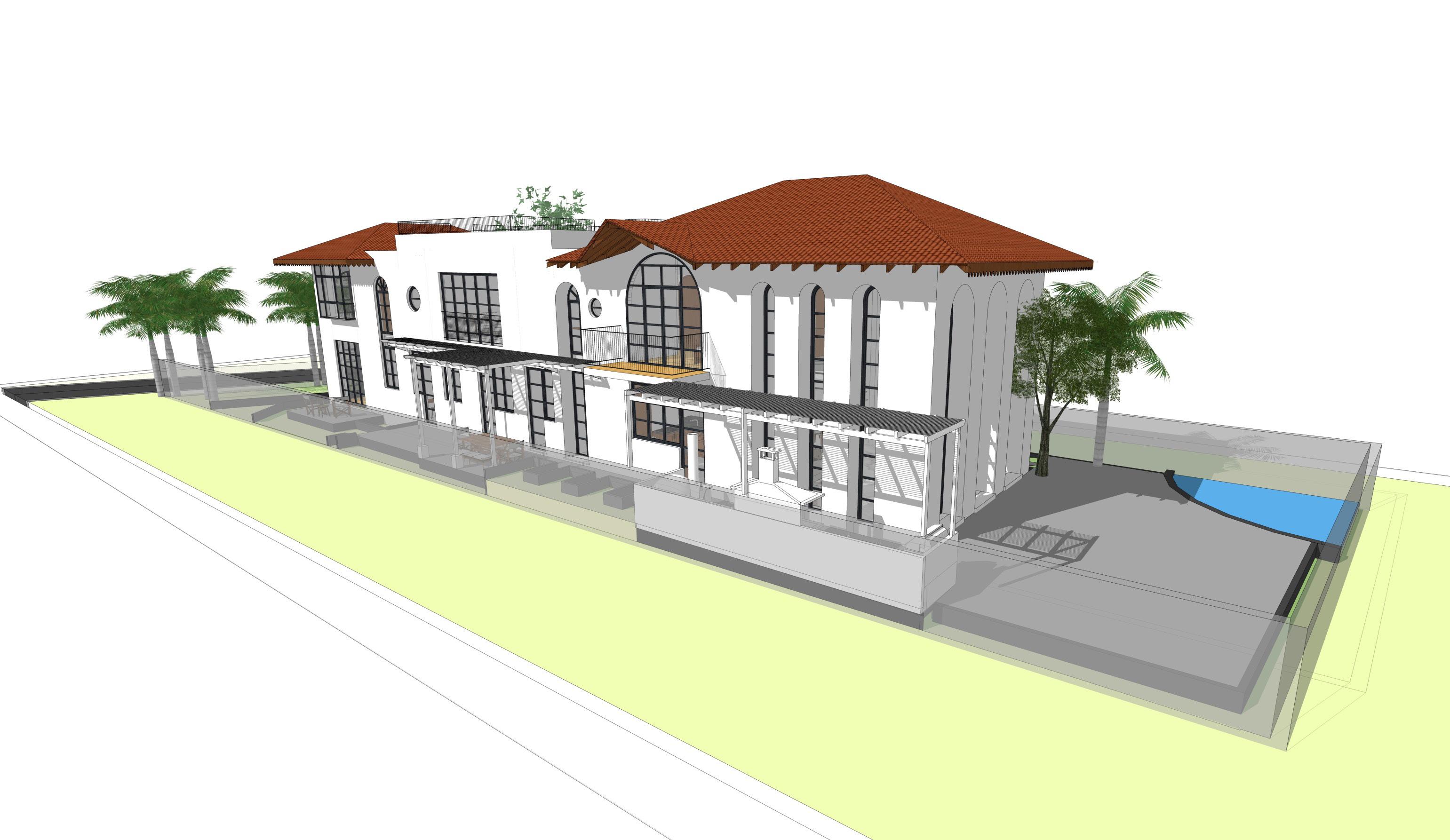
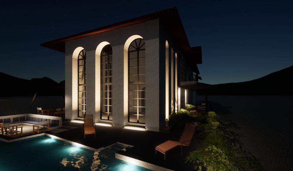
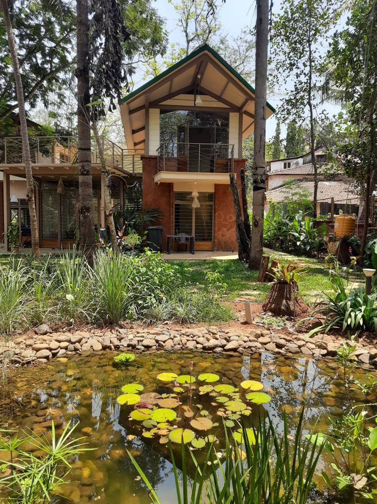
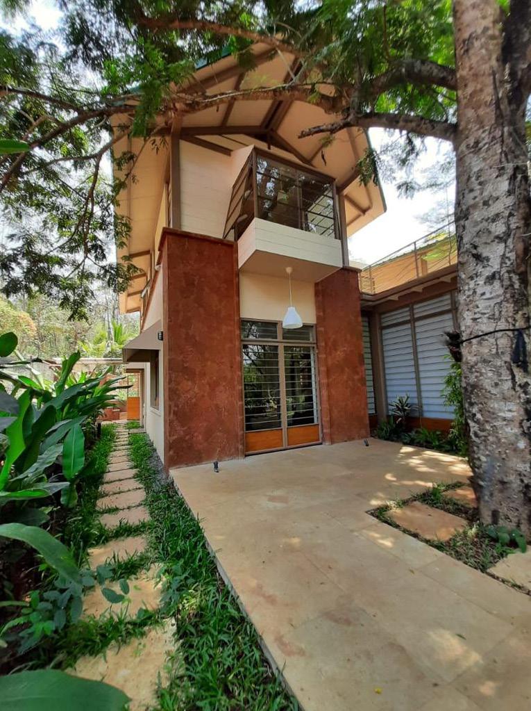
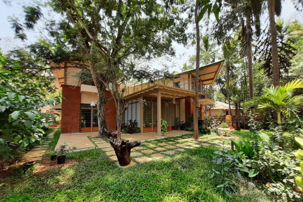
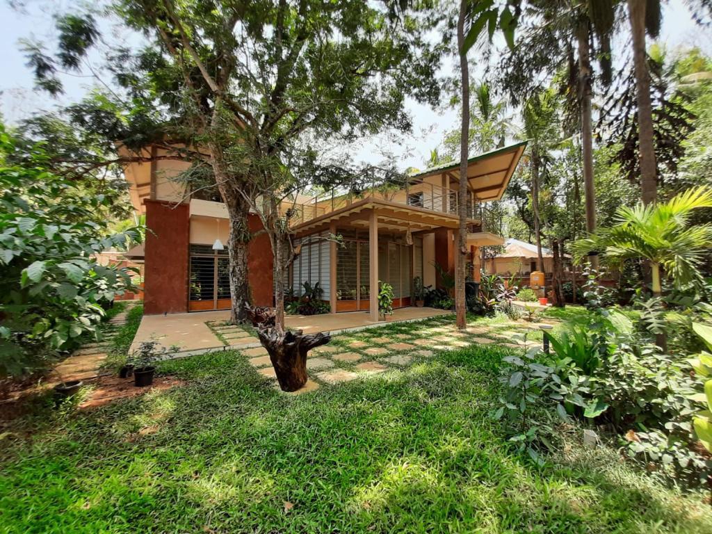
A Greek style inspiration with arched full length windows. This house is designed as a residence and a homestay with the perfect landscape blend, a fine example of making ample amounts of meaning in a more confined space.
18.
Sonu Kapoor Revora, Goa
19.
FIRST FLOOR @ 1:150
GROUND FLOOR @ 1:150

20. PWDR 1.20 x 2.20m UP ENTRANCE LOBBY 1 3 4 DECK 2.15 x 2.00m GUEST LOBBY 1.50 x 2.00m GUEST BEDROOM 3.80 x 5.25m BATH 2.85 x 1.60m DRESSER 2.85 1.55m BATH 2.40 x 1.30 m DRESSER 2.15 x 1.50m STAFF BEDROOM 3.65 2.25m STAFF BEDROOM 3.65 x 2.25m KITCHEN 5.00 x 3.75m UTILITY 2.20 3.65m LIVING ROOM 5.10 6.80m BAR DINING 5.00 x 2.30m STUDY 2.20 x 2.00m BATH 2.40 x 1.30 m STAFF PANTRY 1.90 x 2.25 m -0.12 +0.33 +0.33 +0.33 -0.12 -0.12 -0.24 ±0.00 -0.12 -0.36 -0.48 -0.12 ±0.00 -0.36 -0.48 -0.24 ±0.00 -0.12 -0.24 -0.36 -0.48 -0.24 -0.36 -0.48 -0.12 -0.12 ±0.00 ±0.00 ±0.00 -0.45 -0.30 -0.15 -0.12 -0.12 -0.48 -0.12 ±0.00 -0.24 -0.36 -0.12 ±0.00 -0.12 -0.12 -0.12 -0.12 SEPTIC TANK NO WELL IN 15m FROM SOAK PIT SP PROPOSED SEPTIC TANK AND SOAK PIT LOCATION RADIUS PROPOSED LOCATION FOR SWIMMING POOL IF EXECUTED UP 1 2 3 4 5 6 7 8 9 10 10 20 19 18 16 15 14 13 12 11 21 17 FAMILY ROOM 5.35 3.75m BAY WINDOW MASTER BEDROOM 3.80 5.25m BALCONY 1.25 x 2.50m BEDROOM 02 3.85 3.65m BALCONY 3.50 1.00m BEDROOM 01 3.85 x 3.65m BALCONY 3.50 1.00m BATH 1.80 x 3.75m DRESSER 2.90 x 3.75m BALCONY 3.80 x 2.00m DN 1 3 4 5 7 9 10 11 12 13 14 15 16 17 18 19 20 DRESSER 1.20 x 2.95m DRESSER 1.20 x 2.95m
HOUSE AT REVORA 06/03/2024 SCALE 1:150 @ A3 N
FLOOR PLANS
HOUSE AT REVORA AREA STATEMENT Ground Floor : 223 sq. m. First Floor : 223 sq. m. Pool : 45 sq. m.
GROUND FLOOR @ 1:100
SECTION AA' @ 1:100
Mangalore roof tiles as per Arch. approval
2''x1''mm Wooden Purlin as per struct.design
2''x1'' Wooden Purlin running vertically along rafter @ 600 c/c -as per struct.design Metal sheet as per Arch. approval
2''x1'' Wooden Purlin as per struct.design
2nd layer Thermal insulation 9mm THK as per arch. approval
Thermal insulation 9mm THL as per arch. approval
12mm thk. cement board as per arch. approval
Decorative Eaves Board as per arch. detail
Wooden rafter 2.5"X5" as per struct. design
21. KITCHEN BEDROOM BEDROOM DINING GROUND Lvl. -0.45m PLINTH Lvl. 0.00m FIRST FLOOR Lvl. 3.45m SPRINGING
Lvl. 7.35m
N
SECTION BB' @ 1:100 ROOF DETAIL @ 1:100
ROOF PLAN @ 1:100
WEST FACADE ELEVATION @ 1:100
EASR FACADE ELEVATION @ 1:100
22. 13 12 15 14 DN 17 19 20 18 16 11 9 10 GROUND Lvl. -0.45m PLINTH Lvl. 0.00m FIRST FLOOR Lvl. 3.45m SPRINGING Lvl. 7.35m GROUND Lvl. -0.45m PLINTH Lvl. 0.00m FIRST FLOOR Lvl. 3.45m SPRINGING Lvl. 7.35m N
NORTH
FACADE ELEVATION @ 1:100
SOUTH FACADE ELEVATION @ 1:100
23. GROUND Lvl. -0.45m PLINTH Lvl. 0.00m FIRST FLOOR Lvl. 3.45m SPRINGING Lvl. 7.35m GROUND Lvl. -0.45m PLINTH Lvl. 0.00m FIRST FLOOR Lvl. 3.45m TERRACE Lvl. 7.20m SPRINGING Lvl. 7.35m
GROUND FLOOR
FIRST FLOOR
24. LIVING ROOM 5.10 X 6.80m BAR KITCHEN 4.70 X 3.75m DINING 4.70 X 3.70m UTILITY 2.20 X 3.65m STUDY 2.20 X 2.00m PWDR 1.20 X 2.20m ENTRANCE LOBBY UP PANTRY 1.90 X 2.50m BATH 2.40 X 1.30m STAFF BEDROOM 3.65 X 2.25m DRESSER 2.15 X 1.50m DRESSER 2.85 X 1.95m BATH 2.85 X 1.60m GUEST BEDROOM 3.80 X 5.25m DECK 2.15 X 2.00m GUEST LOBBY 1.50 X 2.00m LIVING ROOM BELOW BALCONY 1.25 X 2.50m BATH 1.60 X 2.60m UP BATH 1.80 X 3.75m FAMILY ROOM 7.40 X 3.75m DRESSER 2.90 X 3.75m MASTER BEDROOM 3.80 X 5.25m BALCONY 3.80 X 2.00m BALCONY 3.50 X 1.50m BEDROOM 3.85 X 3.65m DRESSER 1.55 X 1.85m DRESSER 2.15 X 1.50m BATH 2.40 X 1.30m STAFF BEDROOM 3.65 X 2.25m
BALCONY 3.50 X 1.50m BEDROOM 3.85 X 3.65m BATH 1.60 X 2.60m DRESSER 1.55 X 1.85m
Ground floor
floor
Renders
First
Miscellaneous works
A compilation of works done across several projects in forms of models, details, sanction drawings, sketches.Details range from MS work, railing, electricals and more.
25.
BB1(550*250), LVL ± 0.00
BB1(550*250), LVL ± 0.00
PB2(300*250), LVL ± 0.00
BB1(550*250), LVL ± 0.00
PB2(300*250), LVL ± 0.00
PB5(300*400), LVL ± 0.00
UFL -0.25
BB1(550*250), LVL -0.25
BB1(550*250), LVL ± 0.00
BB1(550*250), LVL ± 0.00
PB4(230*400), LVL ± 0.00
PB2(300*250), LVL ± 0.00
BB1(550*250), LVL ± 0.00
UFL ± 0.00
BB1(550*250), LVL ± 0.00
BB1(550*250), LVL ± 0.00
BB1(550*250), LVL -0.25
BB1(550*250), LVL ± 0.00
BB1(550*250), LVL0.10
BB1(550*250), LVL ± 0.00
UFL ± 0.00 UFL ± 0.00 UFL ± 0.00
PB2(300*250), LVL ± 0.00
PB5(300*400), LVL ± 0.00
BB1(550*250), LVL ± 0.00
PB5(300*400), LVL ± 0.00
PB4(230*400), LVL ± 0.00
PB2(300*250), LVL ± 0.00
PB5(300*400), LVL ± 0.00
UFL ± 0.00
PB2(300*250), LVL ± 0.00
BB1(550*250), LVL ± 0.00
BB1(550*250), LVL ± 0.00
PB3(230*250), LVL ± 0.00
PB4(230*400), LVL ± 0.00
PB1(300*250), LVL ± 0.00 UFL -0.10
PB4(230*400), LVL ± 0.00 DOWELS TO
UFL -0.25 UFL -0.25
PB5(300*400), LVL ± 0.00
UFL ± 0.00
BB1(550*250), LVL ± 0.00
BB1(550*250), LVL -0.25
BB1(550*250), LVL ± 0.00
BB1(550*250), LVL ± 0.00
LVL0.10
BB1(550*250)

26.
LEFT
BE
FOR MOULDING
BB1(550*250),
REFER STRUCTURAL FRAMING PLAN FOR BASE PLATE DETAIL S:
BED ROOM 02 2970 X 3530 LIVING ROOM 5470 X 5045 KITCHEN 5700 X 3740 MASTER BEDROOM 5470 X 3740 BED ROOM 01 3740 X 3740 DRESSER 1500 X 2275 PASSAGE 1500 WIDE DINING ROOM 3740 X 3970 VERANDAH 2100 WIDE EXISTING WELL D1 W1 W1 W1 W1 W1a W1a DW2 DW1 W1 W1a W1 D1 D2 D3 DRESSER 1200 X 2275 FFL + 0.025 UFL 0.100 TOILET 2725 X 1400 SKYLIGHT ABOVE TOILET 2125 X 2045 TOILET 2125 X 2045 D1A FFL + 0.075m UFL ± 00.0m S: -L: 3075 S: 1275 L: 3075 S: -L: 3075 W1 W1 S: 0975 L: 3075 S: -L: 3075 D1 S: 0975 L: 3075 S: -L: 2475 W1a W1b W1a S: 0975 L: 3075 S: 0975 L: 3075 S: 0975 L: 3075 S: 1275 L: 3075 S: 1275 L: 3075 S: 1275 L: 3075 S: 0975 L: 3075 S: 0975 L: 3075 S: 0975 L: 3075 S: 0975 L: 3075 S: 0975 L: 3075 S: 1275 L: 3075 S: 1275 L: 3075 S: 0975 L: 3075 S: 1275 L: 3075 W1 W1 FFL 0.075 m UFL ± 00.0m FFL + 0.063m UFL 0.250m FFL 0.063m UFL 0.250m FFL + 0.063m UFL 0.250m FFL + 0.075 m UFL ± 00.0m FFL + 0.075 m UFL ± 00.0m FFL + 0.075 m UFL ± 00.0m FFL 0.025 UFL 0.100 D1B D1B SUNAINA R-01 17/01/2024 JEEVAN SEBASTIAN MOZAIC 1 Design Valley, Alto-Porvorim, Bardez - GOA 403521 Tel: (+91) 832 2410471 2 Fax: (+91) 832 2412570 Em: architecture@mozaic.in url: www.mozaic.in PROJECT CLIENT DRAWN BY DRAWING TITLE PLINTH AND MASONRY LAYOUT STATUS CHECK BY DATE JS-AR-EB-PL-01 DWG. N0. REVISION N0. SCALE WORKING DRAWING G.F.C REVISIONS SR. NO. DESCRIPTION DATE 1:50 @ A1 GENERAL NOTES: This drawing is good for core and shell construction. For internal finishes refer I.D drawing Drawings shall be read in conjuction with all relevant structural and associated service drawing. No dimensions are to be scaled off this drawing and only printed dimensions to be read. Any descripancies should be brought to the notice of the Architect Consultant before execution. All dimensions are in mm unless otherwise specified This drawing is to be read for the purpose of core and shell construction. For internal finishes refer I.D drawing 1. 2. 3. 4. 5. 6. All Arch drawings to be read in conjunction with RCC/ Services Drawings as per List below 7. C O P Y R G H T 2 0 2 B Y M O Z A C A L L R I G H T S R E S E R V E D. N O P A R T O F T H E D R A W N G S H O U L D B E R E P R O D U C E D O R D S T R B U T E D N A N Y F O R M O R B Y A N Y M E A N S O R S T O R E D N A D A T A B A S E O R A N Y R E T R E V A B L E S Y S T E M W T H O U T T H E P R O R P E R M S S O N O F T H E A R C H T E C T. House for Sebastian’s at Thivim SCALE 1 : 50 PLINTH MARKING PLAN 1 SCALE 1 50 MASONRY PLAN 2 1:100 @ A3 MATERIAL LEGEND 230mm thk. Laterite stone wall with 12mm thk. internal plaster and 18 mm thk. external plaster 115mm thk. interior brick wall with 12mm thk. cement plaster on both side. R.C.C structure ATUL S. 08/01/2024 R-01 R-00 17/01/2024 MODIFIED PLINTH EXTENTS
-L: 3075
27. N Scale: 1:40 PLAN 1 1
ELEVATION
ELEVATION
ELEVATION 3 4
Scale: 1:40
1 2 Scale: 1:40
2 3 Scale: 1:40
ELEVATION
NTS KEY PLAN 0
Scale: 1:40
4 5

28. 1138 395 743 605 908 600 600 600 2260 600 3320 462 1335 150 150 150 150 150 SB-A7 SB-A4 SB-A9 SB-A2 SB-A11 SB-A10 SB-A3 SB-A1 SB-A8 A1-A A1-A A2-D A2-E A3-A A7-A 908 600 A7-C A7-B A9-D A9-E A9-E 1138 A2-D A2-C A2-C A2-E 900 900 832 810 1660 920 350 810 832 1138 1138 G SB-A7 SB-A4 SB-A9 SB-A2 SB-A13 SB-A10 SB-A3 SB-A1 SB-A8 C C F A2-C A1-A A1-A
A3-A A9-A A9-D A7-A A9-C A7-B SB-A12 A1-B AC/GEYSER POINT as per services planning WALL MOUNT CHIMNEY/R.O. ABOVE COUNTER BELOW DESK PLUG POINT 950 N
A2-D A2-D
C1 C2
29.
C3 C7 C8 C4 C6 C10 C9 1138 395 743 908 600 600 600 2260 600 3320 462 1335 150 150 150 150 150 SB-A7 SB-A4 SB-A9 SB-A2 SB-A11 SB-A10 SB-A3 SB-A1 SB-A8 A1-A A1-A A2-D A2-E A3-A A7-A 908 600 A7-C A7-B A9-D A9-E A9-E 1138 A2-D A2-C A2-C A2-E 900 900 832 810 1660 920 350 810 832 1138 1138
C7 C8
C6 C10 C9 G SB-A7 SB-A4 SB-A9 SB-A2 SB-A13 SB-A10 SB-A3 SB-A1 SB-A8 C C F A2-C A1-A A1-A A2-D A2-D A3-A A9-A A9-D A7-A A9-C A7-B SB-A12 A1-B AC/GEYSER POINT as per services planning WALL MOUNT CHIMNEY/R.O. ABOVE COUNTER BELOW DESK PLUG POINT 950 N
C1 C2 C3
C4
30.
ELEVATION 2
BALCONY 01 AND 03 PLAN
SECTION BB'
SCALE 1 : 75
ELEVATION 3 ELEVATION
31. BALCONY 8.62X3.45 8620 3454 1374 2748 2523 1262 2748 1374 350 1215 1215 375 1000 755 2250 2250 1490 1115 1115 50 44 172 180 164 100X60X6 MM M.S FLAT 40X40X6 MM M.S FLAT 25X50 MM WOODEN HANDRAIL 14X14 MM M.S SQUARE BARS 25X25X3 MM M.S SHS A A' B' 2 FFL + 3.990 m UFL +3.950 m 647 879 14 984 984 833 164 164 25 DETAIL 'A' 879 647 1374 1374 1262 1262 N
1
75
SCALE
:
1 : 30 DETAIL @ 'A'
SCALE
SCALE 1 : 75 SECTION AA'
1 75
32. POOL 0.45 PLAN OF FRONT COMPOUND WALL AND GATE A' FRONT COMPOUND WALL AND GATE SECTION B-B' B' PLAN OF SIDE COMPOUND WALL PART ELEVATION OF COMPOUND WALL DETAILS SITE BOUNDARY WALL ARCHITECT: OWNER: DATE: MOZAIC 1 DESIGN VALLEY, ALTO-PORVORIM, BARDEZ- GOA 403521 TEL: (+91) 832 2410471 2 FAX: (+91) 832 2412570 Em: architecture@mozaic.in url www.mozaic.in DEAN D'CRUZ CA 1985 09242 DIVYA GUPTA 12 JANUARY 2024 PROJECT: PROPOSED RESIDENCE AND COMPOUND WALL AT GUIRIM NORTH GOA PERMISSIBLE FLOOR AREA CALCULATION A + (B or C whichever is the lowest) iv FAR x Effective plot area 25% of (A) Permissible floor area ii 91.95 367.8 367.8 AREA STATEMENT 10 G.F. Built Up EFFECTIVE COVERED AREA FOR GROUND COVERAGE CALCULATIONS Total Effective covered area Coverege % ( Total Effective covered area x 100 eff. plot area Zone F.A.R permissible Covered permissible 2 6 7Covered area permissible Areas (sqm) 40% x effective plot area Length of compound wall = 98.79 mt. Main gate opening = 4.5 mt. Total Ground floor F.A.R. 9 First floor Built Up AreaDeductionsFloor Area Level F.A.R B.U.A.- Deductions 245.2 99.26 221.27 18.23 145.94 203.04 466.47 60 56.92 245.2 40 40% 245.2 1 VP-2 A B BUILT UP Main House 1 Areas (sqm) FOR INFRASTRUCTURE TAX ii 348.98 117.49 Net effective plot area (sqm) 8 Main House 3 R/W area (sqm)iii F.A.R x R/W area 0 C Pool 2 31.7 3Total 498.17 Total area Plot 1-L Survey no 36 613 sqm ( Total Floor area x 100 ) / eff. plot area 4 5 466.47 D O O R W N D O W S C H E D U E W NDOWS TYPE WIDTH (m) HE GHT (m) LINTEL HT (m S LL HT (m) REMARKS NOs D O O R W N D O W S C H E D U E TYPE WIDTH (m) HE GHT (m) LINTEL H m S HT (m) REMARKS DOORS NOs D1 0.90 - 3 0.80 D2 - 4 D3 1.10 - 2 2.70 D5 - 1 0.70 D6 - 1 0.90 D1a - 1 0.80 D2a - 1 W1 3.00 1 4 S ng P ne s W4 2.25 1 W2 2.25 1 W5 2.25 3 S d g F ed g a s bo e 4 W6 2.25 3 W3 1.50 2 2.70 2.70 2.40 SD1 - 1 1 S u e Sw g SD4 - 1 2.70 1.20 2.70 1S d n Doo W7 4.50 1 3.40 2.70 W3a 1.50 2 1.80 0.90 S d ng Do W4a 2.25 1 2.70 1.25 0.45 V1 0.75 5 2.70 1.20 1.50 3 S ng P ne s Ba W ndow uve d Ven a o 2 S d g Pa e D4 0.87 - 2 1 S u e Sw g V2 1.50 1 5.11 .785 4.32 V3 2.25 5 2 613 sqm SLOPE SLOPE V2a 1.50 0.8 4 2.40 V1a 0.75 1.65 0.8 2.40 1.65 2.40 1.65 0.75 2.25 1.45 0.45 1.25 2.70 2.70 0.45 2.70 2.25 1.65 0.75 2.40 1.65 0.75 2.40 1.65 0.75 2.40 3.71 0.75 4.46 2 S ng P ne s 3 S ng P ne s 4 S d F ed g ass bo e Ba W ndow uve d Ven a o uve d Ven a o uve d Ven a o uve d Ven a o 0.90 SD3 - 1 2.70 0.90 2.70 1 S d n Doo SD2 - 1 2.70 4.50 2.70 4 S ng D o 2.70 2.70 2.70 2.70 2.70 2.70 2.40 1 S u e Sw g 1 S u e Sw g 1 S u e Sw g 1 S u e Sw g 1 S u e Sw g 1 S u e Sw g
1:3:6 P.C.C OUTLET 20) OPENING SEPTIC TANK'S DIMENSIONS 2.15 SEPTIC TANK DETAILS AREA SQ.M. BLOCK A BUILT-UP AREA (GROUND FLOOR) 145.94 58.41 DEDUCTIONS FLOOR AREA NET TOTAL BUILT-UP AREA DEDUCTIONS 245.2 99.26 145.94 TOTAL TOTAL 245.2 99.26 19.42 AREA SQ.M. BLOCK A BUILT-UP AREA (FIRST FLOOR) 203.04 DEDUCTIONS FLOOR AREA NET TOTAL BUILT-UP AREA DEDUCTIONS 221.27- 18.23 203.04 TOTAL TOTAL 221.27 18.23 2.70 146.08m2 58.41m2 19.42m2 18.23m2 203.04m2 58.41 19.42 18.23 18.23 21.43m2 21.43 21.43 POOL DETAILS POOL SECTION AA' POOL PLAN 2.70 2.10 2.70 2.70 2.70 2.10 D ARK PHOEN X TUD O COO PO NT RAS RO IT MPLERD PROPOSED COMPOUND WALL VEHICULAR ENTRANCE GATE 3.01 3.05 3.01 6.06 5.02 4.19 5.36 I.C. I.C. I.C. I.C. I.C. 31.54 18.55 13.45 19.90 19.85 SLOPED ROOF w mm n P o EP H - 0 36/1L KEY PLAN KARAN KHOSLA ON PLOT BEARING SURVEY NO. 36/ 1-L STAFF 02 TOILET 3.87 3.4m LIVING/DINING 4.0 8.1m BEDROOM 1.8 1.0m UP STILT AREA (+/-0.0 m) (+/-0.0 m) (+/-0.0 m) BEDROOM 4.8 3.4m MASTER BEDROOM TERRACE 7.3 4.5m (+4.15m) LIVING SPACE 9.3 4.5m BEDROOM STUDY 3.4 2.3m 2.2 1.9m 1.8 2.1m DN 2.25 2.3m BEDROOM 4.6 3.4m 4.8 3.4m 1.3 1.9m 1.8 2.1m (+3.15m) (+3.15m) DN TERRACE 2.3 4.5m (+3.50m) SD1 D3 SD3 V1a V3 W5 W5 W6 W5 W5 W3a D2a D1a D2a D2a KITCHEN 01 KITCHEN-BELOW BATHROOM BATHROOM BATHROOM BATHROOM BATHROOM WC C T BATHROOM S PT C T NK SOA P LAUNDRY ROOM LAUNDRY ROOM 2.4 2.13 EEVERANDAH E b
SITE PLAN
33. O R W N D W S C D U L E TYPE WIDTH (m) H G T (m) LINTEL HT S L T (m) RE AR S D OR NOs D1 1.20 2.30 - 2 S w n 2.30 D2 0.90 2.30 - S e w n D3 0.90 - S e w n D4 0.80 S e w n D5 0.70 S SD1 4.40 5 S SD2 2.00 h e SD3 7.565 h SD4 4.85 h SD5 3.90 h SD6 1.20 SD7 2.00 SD8 0.90 SD9 3.87 SD10 0.75 D6 0.90 2 S w n SD11 3.50 2.35 2.30 2.30 2.30 2.30-2.60 2.602.60 2.602.60 2.602.60 2.602.60 2.602.30 2.302.30 2.30--D2a 0.90 2.30 - S SD1a 4.40 S g g 2.65 2.90 2.9012 h e h S S n g h h S g g 2.30 2.30 2.30 2.30 2.30 2.30 2.30 2.30 2.30 2.30 2.30 2.30 D O R W N D O W S H E D W N OWS LINTEL T 2.60 TYPE S T (m) WIDTH (m) H G T (m) NOs REM R S W1 1.60 2.25 1.00 2.60 W2 1.60 2.25 1.00 W5 V1 V2 V3 V4 2.10 1.70 0.75 1.50 V5 1.20 V6 2.40 1 4 1 4 1 1 W1a 1.50 V1a 1.20 1 3.20 2.30 1.10 1.20 2.30 1.10 1.20 2.90 1.50 1.40 2.30 0.50 1.80 2.90 1.90 1.00 2.30 1.30 1.00 2.90 1.50 1.40 2.90 1.50 1.40 2.90 1.50 1.40 S S L e e Fixed L e e a o L e o L e e a o L e e a o L e e a o S S L e e a o BUILT-UP AREA (GROUND FLOOR) DEDUCTIONS NET TOTAL BUILT-UP AREA DEDUCTIONS 649.3 74.54 TOTAL 74.54 17.26 7.12 17.26 AREA SQ.M. BLOCK BUILT-UP AREA (LOWER GROUND FLOOR) 390.64 FLOOR AREA NET TOTAL 404.74 14.1 390.64 TOTAL 404.74 14.1 14.1 2.30 W3 1.30 5.70 1.00 1 S d g 2.30 W4 1.30 3.23 1.00 1 L e e V7 0.75 1 2.30 0.75 1.55 L e e a o 479.46m2 AREA DIAGRAM GROUND FLOOR PLAN AREA DIAGRAM LOWER GROUND FLOOR PLAN V4a 1.50 1 2.90 1.50 1.40 L LOWER GROUND FLOOR PLAN GROUND FLOOR PLAN ELEVATION 3 ELEVATION 1 ELEVATION 2 COMPOUND WALL DETAILS SEPTIC TANK DETAILS SECTION AA' SECTION BB' LIVING SPACE 7.6 6.4m DINING SPACE DECK 15.0 2.5m 1.6m WIDE 5m wide) ROOF PLAN POOL DETAILS ELEVATION 4 ELEVATION 1 ELEVATION 2 ELEVATION 3 ELEVATION 4 GROUND FLOOR PLAN ARCHITECT: OWNER: DATE: 01/02/2024 MOZAIC 1 DESIGN VALLEY, ALTO-PORVORIM, BARDEZ- GOA - 403521 TEL: (+91) 832 2410471 2 FAX: (+91) 832 2412570 Em: architecture@mozaic.in url www.mozaic.in DEAN D'CRUZ CA / 1985 / 09242 PROJECT: ANINDYA BASU W1b 1.50 4 2.90 1.80 1.00 S S AMALGAMATION OF PLOTS BEARING SURVEY NO. 53/1A AREA STATEMENT Zone Areas (sqm) 1 VP-1 4Total plot area (sqm) after amalgamation F.A.R permissible 2 60 Net effective plot area (sqm) 3 R/W area (sqm) 520.4 5 Total area Plot 1-A Survey no 53/1-A 3671 sqm Total area Plot 1-D Survey no 53/1-D 9 3675 sqm 10 7346 sqm 6590 sqm PERMISSIBLE FLOOR AREA CALCULATION A + (B or C whichever is the lowest) iv FAR x Effective plot area 25% of (A) Permissible floor area 988.5 4266.24 3954 13 EFFECTIVE COVERED AREA FOR GROUND COVERAGE CALCULATIONS Total Effective covered area Coverege % Total Effective covered area 100 ) eff. plot area Covered permissible 8 9Covered area permissible 40% x effective plot area Length of compound wall = 361.46 mt. Main gate opening = 3.5 mt. Total Ground floor F.A.R. 12 Lower ground floor Built Up AreaDeductionsFloor Area Level F.A.R B.U.A.- Deductions 649.3 74.54 404.74 14.1 574.76 390.64 1124.62 15.72 719.88 10.92 40% 2636 A B BUILT UP Main House 1 Areas (sqm) FOR INFRASTRUCTURE TAX 1035.98 88.64 10 Main House iii F.A.R x R/W area 312.24 C Driver's Quarters 2 70.58 3Pool 67.80 Total Floor area 100 eff. plot area 1054.04 Ground floor 70.58 - 70.58 11 Driver's Quarters 3Total 1192.42 Area Under Orchard (sqm) 328 sqm Area Under No Development Slope (sqm) 80 sqm Area Under Settlement (sqm) 6590 sqm 6 7 8 AND NO.53/1D, AND CONSTRUCTION OF PROPOSED RESIDENCE AND COMPOUND WALL AT CURCA, NORTH GOA PLOT PLAN BEFORE AMALGAMATION PLOT PLAN AFTER AMALGAMATION SITE PLAN SURVEY NO. 53 PLOT NO. 1-A AREA : 3671 sqm SURVEY NO. 53 PLOT NO. 1-D AREA : 3675 sqm PLOT AFTER PROPOSED AMALGAMATION AREA : 7346 sqm MAIN HOUSE STAFFSITE BOUNDARY WALL KEY PLAN CURCA PANCHAYAT 100 101 102 103 104 105 106 106 105 104 103 102 100 101 99 98 97 96 95 94 93 92 90 89 89 90 91 92 93 94 95 96 97 98 99 88 87 86 84 83 82 81 80 81 82 83 85 86 87 88 84 85 80 107 107 6.3m2 4.75 m2 17.26m2 OPEN COURTYARD OPEN COURTYARD 390.64m2 CURCA BR DG 12.50 110.50 31.15 121.40 110.50 31.15 39.99 26.63 39.99 26.63 C C T A N C 15.62 5.45 20.52 10.25 22.75 3.51 12.81 PROPOSED COMPOUND WALL VEHICULAR ENTRANCE GATE Kitchen text is not found Kitchen text not found Polyline Area Zero Polyline Area Zero Polyline Area Zero Polyline Area Zero Polyline Area is Zero Polyline Area Zero Polyline Area Zero Polyline Area is Zero Polyline Area Zero Polyline Area Zero Polyline Area Zero Verandah need provided oustside FAR boundary BLOCK/Xref should be removed
34. 5.02 4.0 STORE/washing FIRST FLOOR PLAN GROUND FLOOR PLAN LOWER GROUND FLOOR PLAN ROOF PLAN SLOPE SLOPE SLOPE SLOPE above 5.23 1.50 4.46 1.50 28.61 0.30 3.2 4.77 7.40 1.50 1.50 0.73 6.26 KITCHEN SECTION AA' SECTION BB' ELEVATION 1 ELEVATION 3 ELEVATION 2 ELEVATION 4 TOP LEVEL 3.35 3.35 0.90 0.90 0.90 2.15 KITCHEN BEDROOM DINING LIVING ROOM m GROUND FLOOR FIRST FLOOR 0.84 1.50 - m +6.22 GROUND FLOOR FIRST FLOOR 0.84 1.50 - m +6.22 GROUND FLOOR FIRST FLOOR 0.84 1.50 8.42 - m +6.22 GROUND FLOOR 0.84 1.50 - m TOP LEVEL - 2.38m FIRST FLOOR 1.50 2.80 0.90 SITE PLAN 31.64 SQ.M 5.23 ROOF PLAN GROUND FLOOR PLAN LOWER GROUND FLOOR PLAN SWIMMING POOL 2.50 7.28 1.92 27.60 VEHICULAR ENTRANCE GATE PROPOSED COMPOUND WALL EXISTING ACCESS ROAD 1.85 28.61 1.93 2.85 PROPOSED BUILDING 27.60 15.85 1.92 7.28 8.81 43.79 27.60 15.85 43.79 9.20 8.81 DEDUCTIONS FLOOR AREA NET TOTAL BUILT-UP AREA DEDUCTIONS 31.64 - 31.64 1 31.64 31.64 TOTAL (STILT) 0 AREA SQ.M. BLOCK BUILT-UP AREA (STILT FLOOR) TOTAL 31.64 1 31.64 DEDUCTIONS FLOOR AREA NET TOTAL BUILT-UP AREA - DEDUCTIONS 64.35 - 64.35 1 64.35 64.35 TOTAL (TERRACE) 0 AREA SQ.M. BLOCK BUILT-UP AREA (TERRACE) TOTAL 64.35 1 64.35 PERMISSIBLE FLOOR AREA CALCULATION A + (B or C whichever is the lowest) iv FAR x Effective plot area 25% of (A) Permissible floor area ii 52.35 240 209.4 AREA STATEMENT 9 G.F. Built Up EFFECTIVE COVERED AREA FOR GROUND COVERAGE CALCULATIONS Total Effective covered area Coverege % ( Total Effective covered area x 100 Plot area Zone F.A.R permissible Covered permissible 5 6Covered area permissible Areas (sqm) 40% x effective plot area Length of compound wall = 103.20 mt. Main gate opening = 6.04 mt. Total Ground floor F.A.R. 8 First floor Built Up AreaDeductionsFloor Area Level F.A.R B.U.A.- Deductions 60 40% 1 A B BUILT UP Main House 1 Areas (sqm) FOR INFRASTRUCTURE TAX ii Net effective plot area (sqm) 7 Main House R/W area (sqm) iii F.A.R x R/W area 30.6 C Pool 2 3 Total 2 Total Floor area x 100 eff. plot area 3 4 349 sqm Total area Survey no 108/9 400 sqm 51 sqm 139.6 Terrace Floor iii PLOT AFTER ROAD WIDENING PLOT BEFORE ROAD WIDENING Stilt Floor iv 31.64 31.64 141.75 39.05 102.70 181.30 68.13 113.17 64.35 64.35 0 0 215.87 419.04 203.17 AREA SQ.M. BLOCK A BUILT-UP AREA (GROUND FLOOR) B C 33.89 0.98 13.26 E TOTAL 141.75 12.17 F D 10.39 FLOOR AREA NET TOTAL BUILT-UP AREA DEDUCTIONS 141.75 - 39.05 102.70 17.93 12.68 G H 1.40 6.76 1 3.13 2 0.99 3 18.00 4 0.78 5 9.39 6 TOTAL 39.05 1 3.13 2 0.99 3 18.00 4 0.78 5 9.39 6 DEDUCTIONS (STAIRCASE) (STORE) (VERANDAH) (DUCT) (BALCONY) (STAIRCASE) 6.76 33.89 SQ.M 12.66 SQ.M 17.93 SQ.M 9.39 SQ.M 5.23 2.96 0.82 1.20 6.32 12.00 13.26 SQ.M 5G 215.87 53.96 132.4 37.39 AREA SQ.M. BLOCK A BUILT-UP AREA (1ST FLOOR) B C 33.89 1.12 12.17 9.63 E TOTAL 181.30 23.04 F D 1.31 FLOOR AREA NET TOTAL BUILT-UP AREA DEDUCTIONS 181.30 - 68.13 113.17 17.93 12.68 G H 1.40 2.56 1 11.10 2 4.73 3 11.44 4 9.17 5 0.78 6 TOTAL 1 2 3 4 5 6 DEDUCTIONS (BALCONY) (STAIRCASE) (STAIRCASE) (SITOUT) (BALCONY) (BALCONY) 7.14 11.83 9.38 7 7 (BALCONY) 68.13 8 9 8 (DUCT) 9 (BALCONY) 2.56 11.10 4.73 11.44 9.17 0.78 7.14 11.83 9.38 11.83 SQ.M 11.44 SQ.M 9.18 SQ.M 17.93 SQ.M 1.50 1.50 1.50 3.15 12.13 SQ.M 0.912.54 SQ.M 1.01 1.83 FIRST FLOOR PLAN 169.79 Church PROJECT: PLOTS BEARING SURVEY NO. 108/9 PROPOSED RESIDENCE AT VERLA CANCA, NORTH GOA
FISHTAIL CREEK
STUDY REPORT #1
A beautiful homestay alongside the serence riverfront at Moira, Goa, earned a spot in the AD100 feature. An immense amount of thought and diligence has been put forth in this design intervention that is a standout muse at Moira. The elegance of the building and its materiality blends in with the surrounding landscape seamlessly. A personal insipration of mine that led me to apply here for my internship.
Using materials like jaisalmer stone, teak wood and minimalistic yet effective interior fixtures, this homestay is now on demand here in Goa!
Having access to the riverfront which is a walk away, it enables experiences like fishing and kayaking. Covers your perfect staycation for the year!
35.

36. B A 2' 4' 2' 1' B' A' B' A' D03 2 4 B A 1 4' 1' 3' 3' 3 Y Y D02 D04 D18 500 D02 D07 757 1979 50 2747 1500 975 1800 975 1225 2250 1225 115 900 729 1500 770 600 3150 1 V02 2 3 4 5 6 7 8 9 10 11 12 13 14 15 16 17 18 19 BEDROOM 1 5600 X 3750 FFL + 0.050 m UFL + 0.000 m DRESSER 2170 X 3750 FFL + 0.050 m UFL + 0.000 m FFL + 0.050 m UFL + 0.000 m 3932XKITCHEN 3750 UFLFFL+0.050m +0.000m FFL + 0.038 m UFL -0.012 m 1050TOILET X 1818 3450TOILET X 1817 FFL + 0.038 m UFL -0.012m 4700DINING X3750 UFLFFL+0.050m +0.000m 2588STORE X2985 UFLFFL+0.050m +0.000m R=200T=225 300 3750 4700 900 D11 FFLFFL+1.193m +1.143m UP ENTRANCELOBBY 3700X1270 DECK W02 W02 V02 E MH-SEC-AR-03 W01 W02 3980 3980 5830 3680 4930 650 668 350 800 3450 953 3980 3980 R=165T=280 Line of terrace projection above Deck as per details 230 mm thk. brick wall with 12 mm thk. internal plaster and 18mm thk. external plaster 230 mm thk. brick wall with 12 mm thk. internal plaster and 18mm thk. external plaster. Grill as per detail 1680 50 Chajja projection above A MH-SEC-AR-01 B MH-SEC-AR-01 F MH-SEC-AR-03 900 900 173 745 160 570 300mm thk. laterite stone wall with 12mm thk. internal plaster 570 570 525 750 475 3170 900 683 2435LOBBY X 1818 5 4 2 7 650 9 3080 11 12 13 UP 1 3 6 8 1500 10 14 2433 270 800 800 1470 FFLFFL+1.193m +1.143m 450 900 W02 2170 1400 V01 W04 W03 W05 950 1797 2250 W06 D12 D18 300 300 300 235 385 138 225 600 1200 1017 Grill as per detail UFLFFL+1.205m +1.155m 500 D18 A MH-ELE-AR-01 2 3 4 B MH-ELE-AR-01 D MH-ELE-AR-02 685 C MH-SEC-AR-02 D MH-SEC-AR-02 4350 4069 2681 Planter/Landscape as per detail 230 1848 994 3845 3751 877 602 10066 4439 D01 FFLLIVING+0.050mUFL+0.000m 12050 900 900 2600 900 300 1350 900 3750 975 1800 975 5600 115 2170 115 1932 1135 683 4350 3750 4350 4150 W17 WELL as per detail 1200 4350 750 12050 115 1818 1817 2588 3932 115 230 230 1155 V01 900 115 230 70 230 70 230 70 50 4678 230 70 230 70 70 70 230 70 230 70 1933 80 685 318 1500 F MH-SEC-AR-03 E MH-SEC-AR-03 A MH-SEC-AR-01 B MH-SEC-AR-01 D MH-SEC-AR-02 C MH-SEC-AR-02 115 2170 115 C MH-ELE-AR-02 X X 572 1 Duct Duct C1 C2 C5 C9 C11 C13 C14 C15 C16 C20 C19 C18 C17 C12 C3 C4 C6 C7 C8 C9(A) UFLFFL+0.038m +0.000m DOOR WINDOW SCHEDULE of MAIN HOUSE DOORS TYPE WIDTH (m) HEIGHT (m) SILL HT. (m) (from UFL) LINTEL HT.(m) (from UFL) NOs. REMARKS WINDOWS W1 2.25 1.75 0.90 2.65 Shutter casement, with center fixed and vents on top W2 1.75 0.90 2.65 0.90 Shutter casement with vents on top W3 1.35 1.30 0.95 Fixed glass W4 1.35 1.30 0.65 Fixed glass W5 1.35 1.30 0.75 Fixed glass W6 2.55 0.45 3.00 1.00 Fixed glass W7 2.195 0.45 2.645 1.80 Bay Window W8 1.750 0.90 2.65 0.90 Shutter casement with vents on top W9 1.75 0.90 2.65 1.50 Shutter casement with vents on top W10 1.75 0.90 2.65 0.725 Fixed glass VENTILATORS V1 1.050 1.60 2.65 0.90 Fixed glass with vents on top V2 0.30 2.35 2.65 1.00 V3 1.750 0.90 2.65 0.90 Fixed glass 2.65 2.65 2.65 Fixed glass with vents on top D1 3.75 3.0 - 3.0 Shutter, Sliding D2 1.8 2.65 - 2.65 2 Shutter, Swing with vent on top D3 1.50 2.15 - 2.15 Shutter, Sliding D4 0.90 2.65 - 2.65 1 Shutter, Swing D7 0.65 2.15 - 2.15 Shutter, Sliding D8 4.36 2.15 - 2.15 Shutter, Sliding with center fixed D9 3.00 2.65 - 2.65 2 Shutter, Swing with sides fixed and vent on top D10 0.75 2.65 - 2.65 1 Shutter, Swing with vents on top D11 1.0 2.20 - 2.20 1 Shutter, Swing (Main ent. Door) W17 3.15 - 3.150 4.04 Fixed Glass D12 0.90 2.15 - 2.15 1 Shutter, Swing D18 0.80 2.15 - 2.15 1 Shutter, Swing Talwar Residence At Moira, GOA Vivek Talwar GENERAL NOTES: MATERIAL LEGEND Elevation No. with sheet refernce Section No. with sheet refernce Floor Level / Level - Plan FFL level change FFL UFFL FFL UFFL Floor Level Level - Section MOZAIC 1 Design Valley, Alto-Porvorim, Bardez GOA - 403521 Tel: (+91) 832 2410471 2 Fax: (+91) 832 2412570 Em: architecture@mozaic.in url: www.mozaic.in PROJECT CLIENT DRAWN BY DRAWING TITLE MAIN HOUSE (MH) GROUND FLOOR PLAN PATRISH K P KUMAR STATUS CHECK BY DATE 04.06.2019 MH-PL-AR-01 DWG. N0. R-00 REVISION N0. SCALE 1:50 @ A2 REVISIONS SR. NO. DESCRIPTION DATE This drawing is good for core and shell construction. For internal finishes refer I.D drawing Drawings shall be read in conjuction with all relevant structural and associated service drawing. No dimensions are to be scaled off this drawing and only printed dimensions to be read. Any descripancies should be brought to the notice of the Architect Consultant. All dimensions are in mm unless otherwise specified These drawings are to be read for the purpose of building construction on site. 1. 2. 3. 4. 5. 6. GENERAL LEGEND WORKING DRAWING (For Approval) Detail No. with sheet refernce 1:75 @ A3 A101 Ref A101 Ref ST-01 AR-28 C O P Y R I G H T 2 1 9 B Y M O Z A C A L L R G H T S R E E R V E D. N O P A R T O F T H E D R A W I N G S H O U L D B E R E P R O D U C E D O R D I S T R B U T E D I N A N Y F O R M O R B Y A N Y M E A N S O R S T O R E D I N A D A T A B A S E O R A N Y R E T R E V A B L E S Y S T E M W T H O U T T H E P R O R P E R M S S O N O F T H E A R C H I T E C T. ANNIE AGARWAL 230mm thk. Laterite stone wall with 12mm thk. internal plaster & 18mm thk. external plaster. 115mm thk. interior brick wall with 12mm thk. cement plaster on both side. 80mm thk. cement board (Shera board partition system) 300mm thk. Laterite stone wall with 12mm thk. internal plaster. 75mm thk. brick wall with 12mm thk. cement plaster on inside and 10 mm Shera Board on outside R.C.C structure
37. 1750 500 +3.55 m PERGOLA LEVEL 1495 2650 900 350 655 2100 500 Grill as per detail W10 Grill as per detail D07 D10 3000 Pergola as per detail 80x40mm R.H.S purlins @ 900mm c/c C 900 230 mm thk. brick wall with 12 mm thk. internal plaster and 18mm thk. external plaster 145x82mm M.S main frame as per struc. design KITCHEN FFL +0.050 m UFL ±0.00m 1570 SECTION-C 1 : 75 500 ENTRANCE LOBBY FFL +1.205 m UFL +1.155m TOILET 230 mm thk. brick wall with 12 mm thk. internal plaster and 18mm thk. external plaster 1750 FFL +3.200 m UFL +2.800m 7291 230 mm thk. brick wall with 12 mm thk. internal plaster and 18mm thk. external plaster Well compacted earth fill 200 thk. rubble packing 150mm thk. R.C.C slab 115mm thk. brick work with plaster and paint finish as per arch. approval 172x92mm M.S main ridge frame as per struc. design Puf-panel roofing with 80mm thk. insulation placed on M.S main members as per arch. approval 230 mm thk. wall with 12 mm thk. internal plaster and 18mm thk. external plaster +4.05m 850 FF SILL LEVEL 2150 FFL +3.188 m UFL +2.800m FIRST FLOOR SLAB LEVEL D11 D18 W02 +2.65 m UPPER GROUND LEVEL +6.89 m RIDGE LEVEL +5.80 m +3.15 m GF LINTEL LEVEL ±0.00 m SPRINGING LEVEL +0.90 m GF SILL LEVEL LOWER PLINTH LEVEL B A B A 2650 +1.15 m 350 150 450 25.00° W08 25.00° 2650 900 7291 4050 25.00° 850 900 2150 250 350 1750 900 1764 2664 80x40mm R.H.S purlins @ 900mm c/c Grill as per detail R=165 T=280 100mm thk. laterite band running across the lintel level. 172x92mm M.S main frame as per struc. design
roofing with 80mm thk. insulation placed on M.S main members as per arch. approval 145x92mm M.S main frame as per struc. design 25.00° 3000 450 150 Well compacted earth fill 150mm thk. R.C.C slab 1764 230 mm thk. brick wall with 12 mm thk. internal plaster and 18mm thk. external plaster 230 mm thk. wall with 12 mm thk. internal plaster and 18mm thk. external plaster 200 thk. rubble packing ±0.00 m LOWER PLINTH LEVEL FFL +0.050 m UFL ±0.00m FFL +0.050 m UFL ±0.00m FFL +3.200 m UFL +3.150m +5.80 m SPRINGING LEVEL FIRST FLOOR SLAB LEVEL +3.15 m GF LINTEL LEVEL +4.05 m +2.65 m +0.90 m FF SILL LEVEL +6.89 m RIDGE LEVEL GF SILL LEVEL 2664 2150 2150 3000 1750 3738 1205 12 mm thk. Shera planks(external) and 8mm thk. cement board(internal) with GI framework as per Arch approval 850 230 mm thk. brick wall with 12 mm thk. internal plaster and 18mm thk. external plaster 900 1205 2150 FFL +0.050 m UFL ±0.00m FFL +3.188m UFL +3.150m FFL +3.200 m UFL +3.150m FFL +3.200 m UFL +3.150m 25.00° +5.650 m FLAT SLAB LEVEL D SECTION-D 1 75 D03 D18 13 17 16 15 14 12 11 10 9 8 7 6 5 4 3 2 1 LIVING AREA DINING AREA BEDROOM-3 W09 W08 A B A B D12 D18 DRESSER DRESSER D12 TOILET W08 A' B' A' B' LOBBY DOOR WINDOW SCHEDULE of MAIN HOUSE DOORS TYPE WIDTH (m) HEIGHT (m) SILL HT. (m) (from UFL) LINTEL HT.(m) (from UFL) NOs. REMARKS WINDOWS W1 2.25 1.75 0.90 2.65 Shutter casement, with center fixed and vents on top W2 1.75 0.90 2.65 0.90 Shutter casement with vents on top W3 1.35 1.30 0.95 Fixed glass W4 1.35 1.30 0.65 Fixed glass W5 1.35 1.30 0.75 Fixed glass W6 2.55 0.45 3.00 1.00 Fixed glass W7 2.195 0.45 2.645 2 1.80 Bay Window W8 1.750 0.90 2.65 8 0.90 Shutter casement with vents on top W9 1.75 0.90 2.65 1.50 Shutter casement with vents on top W10 1.75 0.90 2.65 2 0.725 Fixed glass VENTILATORS V1 1.050 1.60 2.65 0.90 Fixed glass with vents on top V2 0.30 2.35 2.65 1.00 V3 1.750 0.90 2.65 0.90 Fixed glass 2.65 2.65 2.65 Fixed glass with vents on top D1 3.75 3.0 - 3.0 Shutter, Sliding D2 1.8 2.65 - 2.65 Shutter, Swing with vent on top D3 1.50 2.15 - 2.15 Shutter, Sliding D4 0.90 2.65 - 2.65 Shutter, Swing D7 0.65 2.15 - 2.15 2 Shutter, Sliding D8 4.36 2.15 - 2.15 Shutter, Sliding with center fixed D9 3.00 2.65 - 2.65 Shutter, Swing with sides fixed and vent on top D10 0.75 2.65 - 2.65 Shutter, Swing with vents on top D11 1.0 2.20 - 2.20 Shutter, Swing (Main ent. Door) W17 3.15 - 3.150 4.04 Fixed Glass D12 0.90 2.15 - 2.15 Shutter, Swing D18 0.80 2.15 - 2.15 Shutter, Swing Talwar Residence At Moira, GOA Vivek Talwar GENERAL NOTES: MATERIAL LEGEND Elevation No. with sheet refernce Section No. with sheet refernce Floor Level Level - Plan FFL level change FFL UFFL FFL UFFL Floor Level Level Section MOZAIC 1 Design Valley, Alto-Porvorim, Bardez - GOA 403521 Tel: (+91) 832 2410471 2 Fax: (+91) 832 2412570 Em: architecture@mozaic.in url: www.mozaic.in PROJECT CLIENT DRAWN BY DRAWING TITLE MAIN HOUSE (MH) SECTIONS STATUS CHECK BY DATE MH-SEC-AR-02 DWG. N0. R-00 REVISION N0. SCALE 1:50 @ A2 REVISIONS SR. NO. DESCRIPTION DATE This drawing is good for core and shell construction. For internal finishes refer I.D drawing Drawings shall be read in conjuction with all relevant structural and associated service drawing. No dimensions are to be scaled off this drawing and only printed dimensions to be read. Any descripancies should be brought to the notice of the Architect Consultant. All dimensions are in mm unless otherwise specified These drawings are to be read for the purpose of building construction on site. 1. 2. 3. 4. 5. 6. GENERAL LEGEND WORKING DRAWING Detail No. with sheet refernce 1:75 @ A3 A101 Ref A101 Ref ST-01 AR-28 C O P Y R G H T 2 1 8 B Y M O Z A I C A L L R G H T S R E S E R V E D. N O P A R T O F T H E D R A W N G S H O U L D B E R E P R O D U C E D O R D S T R I B U T E D N A N Y O R M O R B Y A N Y M E A N S O R S T O R E D N A D A T A B A S E O R A N Y R E T R E V A B L E S Y T E M W I T H O U T T H E P R O R P E R M S S O N O F T H E A R C H T E C T. ANNIE AGARWAL PATRISH K P KUMAR 08.04.2019 230mm thk. Laterite stone wall with 12mm thk. internal plaster & 18mm thk. external plaster. 115mm thk. interior brick wall with 12mm thk. cement plaster on both side. 80mm thk. cement board (Shera board partition system) 300mm thk. Laterite stone wall with 12mm thk. internal plaster. 75mm thk. brick wall with 12mm thk. cement plaster on inside and 10 mm Shera Board on outside R.C.C structure
Puf-panel
38. +5.80 m W08 350 1750 1750 900 1300 1350 900 D18 900 500 3000 900 W05 Grill as per detail 2650 W08 1750 V03 W08 D10 350 900 3 1 W02 W02 4 4 3 2 1 2 80x40mm R.H.S purlins @900mm c/c Well compacted earth fill
roofing with 80mm thk. insulation placed on R.H.S members as per arch. approval A 145x82mm M.S main frame as per struc. design SECTION-A 1750 2650 TOILET 200 thk. rubble packing FFL +0.050 m UFL ±0.00m 150mm thk. R.C.C slab 115mm thk. brick work with plaster and paint finish as per arch. approval 230 mm thk. brick wall with 12 mm thk. internal plaster and 18mm thk. external plaster 115mm thk. brick work with plaster and paint finish as per arch. approval W01 300 mm thk. laterite wall with 12 mm thk. internal plaster. 900 500 500 W07 2200 350 1750 350 350 2650 STAFF ROOM FFL +3.200 m UFL +3.150m FFL +3.188 m UFL +3.150m BEDROOM FFL +3.200 m UFL +3.150m STORE KITCHEN SPRINGING LEVEL FFL +0.050 m UFL ±0.00m G.F SILL LEVEL DINING ROOM FFL +0.050 m UFL ±0.00m G.F LINTEL LEVEL FIRST FLOOR SLAB LEVEL +3.15 m LIVING AREA LEVEL +2.65 m +4.05m F.F SILL LEVEL +0.90 m ±0.00 m 450 1 75 150 3000 3000 2650 300 3000 900 1795 3150 2650 1750 2650 350 350 500 2150 2650 350 1750 900 1750 900 2650 900 W08 V01 W08 3000 350 1600 1050 V03 W02 W02 115mm thk. brick work with 12mm thk. plaster on both sides and paint finish as per arch. approval SECTION-B Puf-panel roofing with 80mm thk. insulation placed on R.H.S members as per arch. approval 80x40mm R.H.S purlins @900mm c/c B 300 1 75 TOILET D02 2650 V02 D18 D09 900 2650 3150 2350 500 FFL +3.200 m UFL +3.150m 1788 145x82mm M.S main frame as per struc. design 230 mm thk. brick wall with 12 mm thk. internal plaster and 18mm thk. external plaster 115mm thk. brick work with plaster and paint finish as per arch. approval 350 300 mm thk. laterite wall with 12 mm thk. internal plaster V01 BEDROOM-2 FFL +3.200 m UFL +3.150m FFL +3.188 m UFL +3.150m FAMILY ROOM 1600 2350 2650 1050 300 750 2200 2650 350 1750 900 350 350 FFL +0.050 m UFL ±0.00m FFL +0.050 m UFL ±0.00m DRESSER TOILET 300 FFL +0.038m UFL ±0.00m BEDROOM-1 +4.05 m G.F SILL LEVEL 150mm thk. R.C.C slab +3.15 m Well compacted earth fill 200 thk. rubble packing FIRST FLOOR SLAB LEVEL G.F LINTEL LEVEL LIVING AREA LEVEL F.F SILL LEVEL +0.90 m +2.65 m ±0.00 m 4' 3' 2' 1' 4' 3' 2' 1' 2650 450 +5.80 m SPRINGING LEVEL W07 DOOR WINDOW SCHEDULE of MAIN HOUSE DOORS TYPE WIDTH (m) HEIGHT (m) SILL HT. (m) (from UFL) LINTEL HT.(m) (from UFL) NOs. REMARKS WINDOWS W1 2.25 1.75 0.90 2.65 2 Shutter casement, with center fixed and vents on top W2 1.75 0.90 2.65 0.90 Shutter casement with vents on top W3 1.35 1.30 0.95 Fixed glass W4 1.35 1.30 0.65 Fixed glass W5 1.35 1.30 0.75 Fixed glass W6 2.55 0.45 3.00 1.00 Fixed glass W7 2.195 0.45 2.645 1.80 Bay Window W8 1.750 0.90 2.65 0.90 Shutter casement with vents on top W9 1.75 0.90 2.65 1.50 2 Shutter casement with vents on top W10 1.75 0.90 2.65 0.725 Fixed glass VENTILATORS V1 1.050 1.60 2.65 0.90 Fixed glass with vents on top V2 0.30 2.35 2.65 1.00 V3 1.750 0.90 2.65 0.90 Fixed glass 2.65 2.65 2.65 Fixed glass with vents on top D1 3.75 3.0 - 3.0 4 Shutter, Sliding D2 1.8 2.65 - 2.65 Shutter, Swing with vent on top D3 1.50 2.15 - 2.15 2 Shutter, Sliding D4 0.90 2.65 - 2.65 Shutter, Swing D7 0.65 2.15 - 2.15 1 Shutter, Sliding D8 4.36 2.15 - 2.15 2 Shutter, Sliding with center fixed D9 3.00 2.65 - 2.65 Shutter, Swing with sides fixed and vent on top D10 0.75 2.65 - 2.65 Shutter, Swing with vents on top D11 1.0 2.20 - 2.20 Shutter, Swing (Main ent. Door) W17 3.15 - 3.150 4.04 Fixed Glass D12 0.90 2.15 - 2.15 Shutter, Swing D18 0.80 2.15 - 2.15 Shutter, Swing Talwar Residence At Moira, GOA Vivek Talwar GENERAL NOTES: MATERIAL LEGEND Elevation No. with sheet refernce Section No. with sheet refernce Floor Level Level Plan FFL level change FFL UFFL FFL UFFL Floor Level / Level - Section MOZAIC 1 Design Valley, Alto-Porvorim, Bardez GOA - 403521 Tel: (+91) 832 2410471 2 Fax: (+91) 832 2412570 Em: architecture@mozaic.in url: www.mozaic.in PROJECT CLIENT DRAWN BY DRAWING TITLE MAIN HOUSE (MH) SECTIONS STATUS CHECK BY DATE MH-SEC-AR-01 DWG. N0. R-00 REVISION N0. SCALE 1:50 @ A2 REVISIONS SR. NO. DESCRIPTION DATE This drawing is good for core and shell construction. For internal finishes refer I.D drawing Drawings shall be read in conjuction with all relevant structural and associated service drawing. No dimensions are to be scaled off this drawing and only printed dimensions to be read. Any descripancies should be brought to the notice of the Architect Consultant. All dimensions are in mm unless otherwise specified These drawings are to be read for the purpose of building construction on site. 1. 2. 3. 4. 5. 6. GENERAL LEGEND WORKING DRAWING Detail No. with sheet refernce 1:75 @ A3 A101 Ref A101 Ref ST-01 AR-28 C O Y R G H T 2 0 8 B Y M O Z A C A L L R G H T S R E S E R V E D. N O P A R T O F T H E D R A W N G S H O U L D B E R E P R O D U C E D O R D S T R B U T E D N A N Y F O R M O R B Y A N Y M E A N S O R S T O R E D N A D A T A B A S E O R A N Y R E T R E V A B L E S Y S T E M W T H O U T T H E P R O R P E R M S S O N O F T H E A R C H T E C T. ANNIE AGARWAL PATRISH K P KUMAR 08.04.2019 230mm thk. Laterite stone wall with 12mm thk. internal plaster & 18mm thk. external plaster. 115mm thk. interior brick wall with 12mm thk. cement plaster on both side. 80mm thk. cement board (Shera board partition system) 300mm thk. Laterite stone wall with 12mm thk. internal plaster. 75mm thk. brick wall with 12mm thk. cement plaster on inside and 10 mm Shera Board on outside R.C.C structure
Puf-panel
39.
Key takeaways

The use of Laterite is a noticable characteristic of this building.
Laterite is abundantly found here and hence is a primary building material, used for cladding, retaining strctures and even foundation at times. It’s high water proof feature and durability make it a boon for construction.
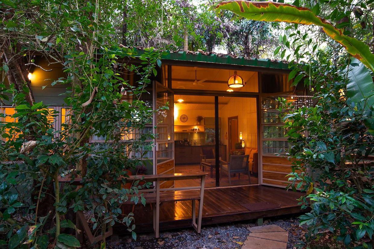
- Incorporate elements that foster a deep connection with nature, such as large windows framing scenic views, outdoor living spaces immersed in the forest canopy, and natural materials that evoke the forest’s tranquility.
- Seamlessly blend the architecture with the lush forest surroundings and natural water features, creating a harmonious relationship between the built environment and nature.
- Pay homage to the local culture and heritage of Goa through architectural elements, materials, and design motifs inspired by traditional Goan architecture, fostering a sense of place and authenticity for guests.
- Blur the boundaries between indoor and outdoor spaces, allowing guests to seamlessly transition between the comfort of the homestay and the serenity of the forest landscape, enhancing their connection with nature.
- Consider the temporal dynamics of architecture, designing spaces that evolve over time and age gracefully, embracing impermanence and change as integral aspects of the architectural narrative.
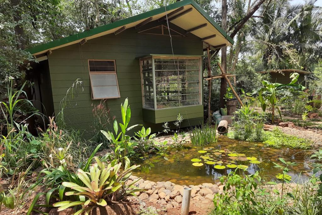
- Something which really struck a note for me, strolling towards the rear of the house, we find ourselves in a tropical oasis, referred to as a “food forest”. Here, vibrant fire spikes, chains of glory, bamboo, mango, coffee, turmeric, ginger, cacao, bromeliads, and towering money plants wind their way up the tree trunks, reaching for the sunlight. The sense on connect one can find with themselves and the ever growing landscape around harbors a new sense of enlightenment within.
40.
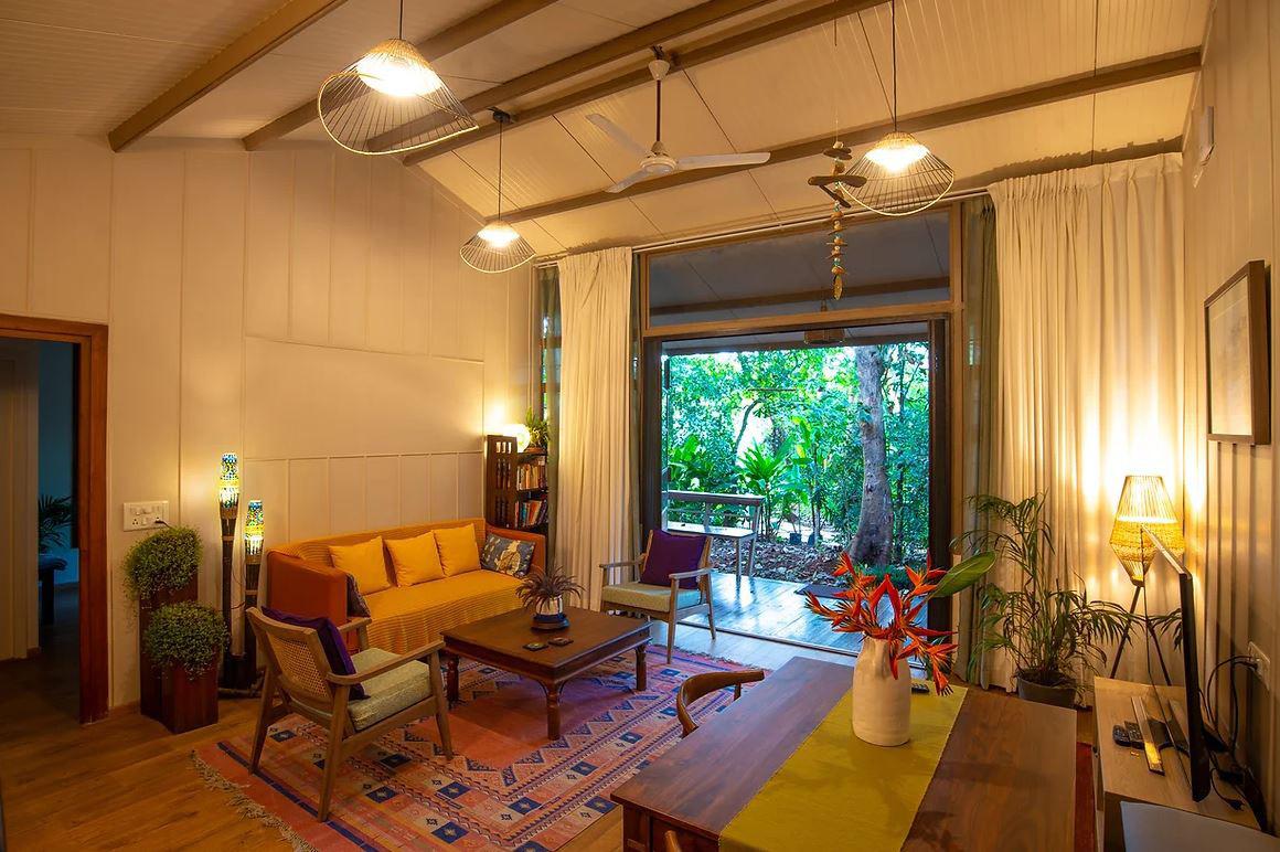
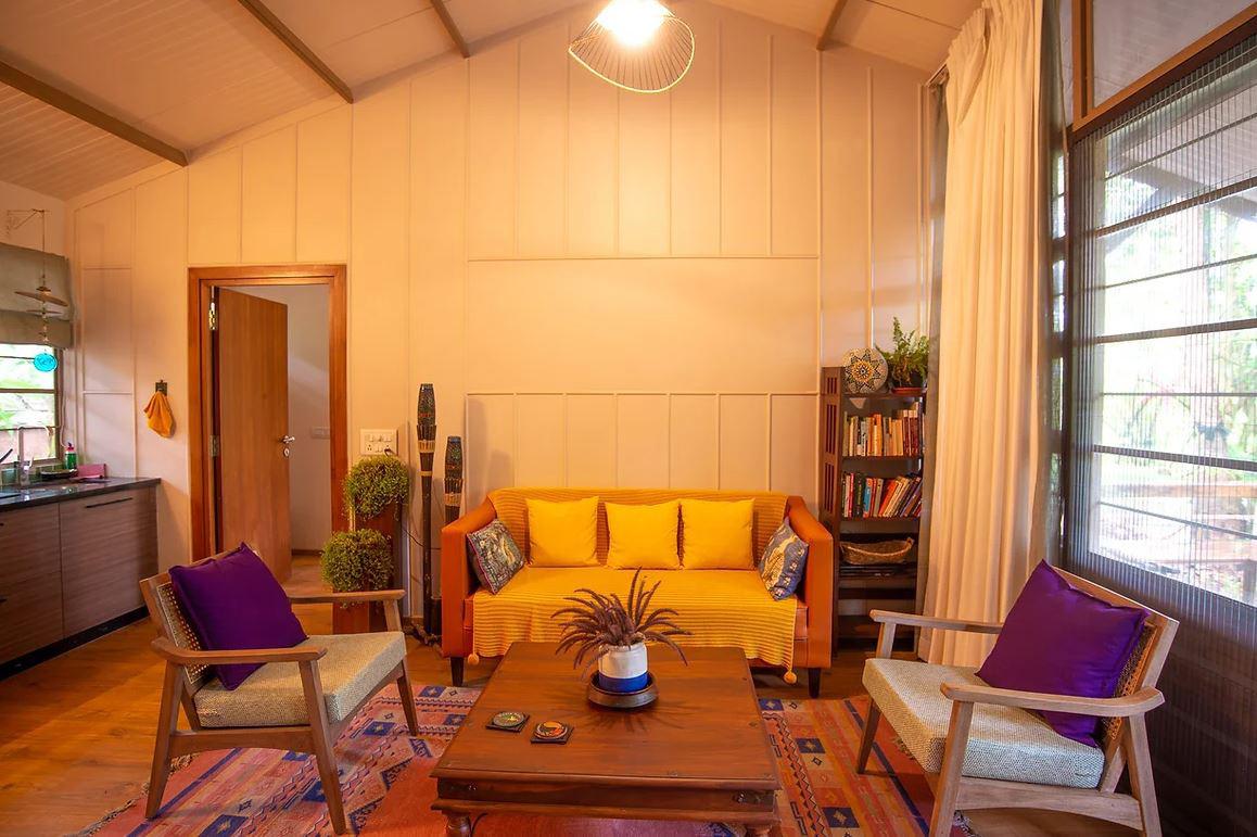
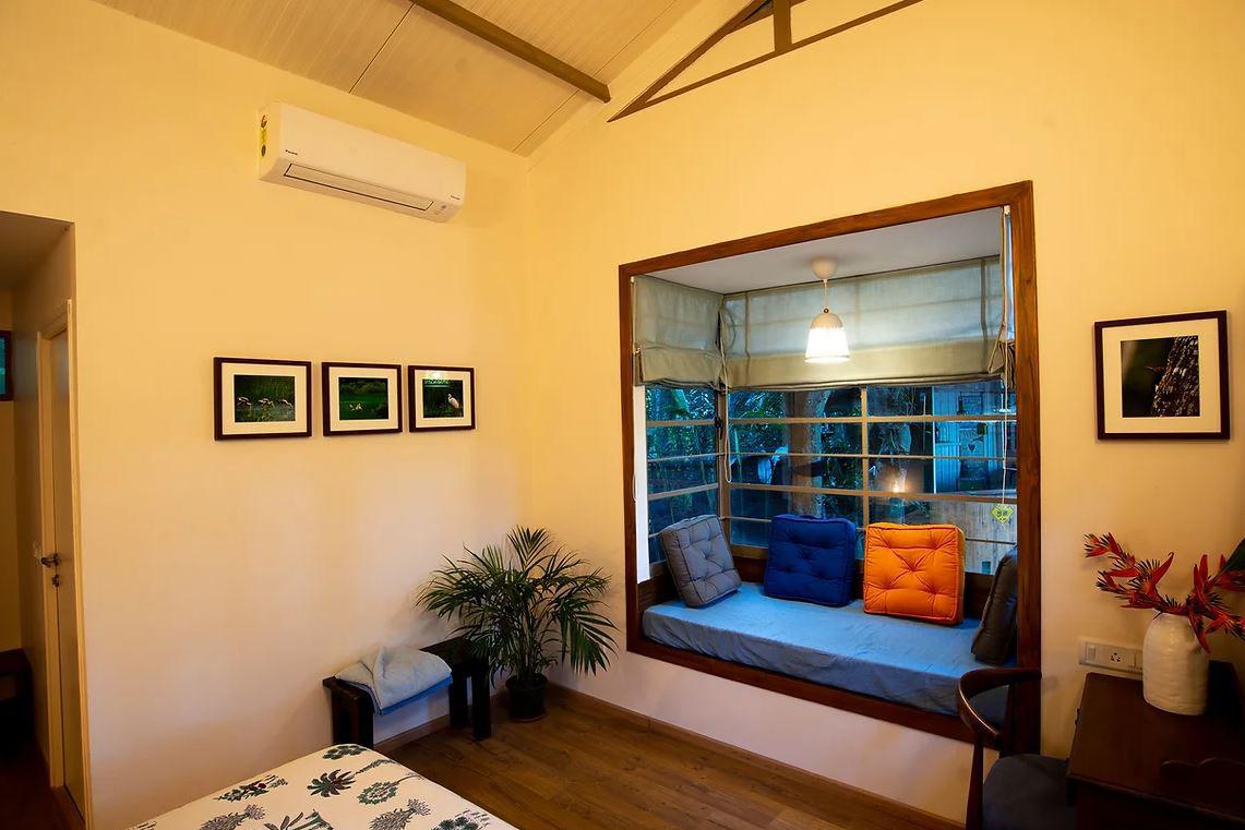
Interiors - Just gives a sense of basking in the sun with yet this sense of a cool breeze from the surrounding forest
Exteriors - Exposed laterite, wooden rafters, glass windows stretching from sill to beam opening up the house to the surrounding.
Karwar Cathedral
STUDY REPORT #2
- The Cathedral of Our Lady of Assumption, also known as the Karwar Cathedral, The cathedral has a rich history in it and has been an important center of worship for Catholics in Karwar and the surrounding areas.
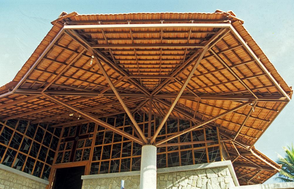
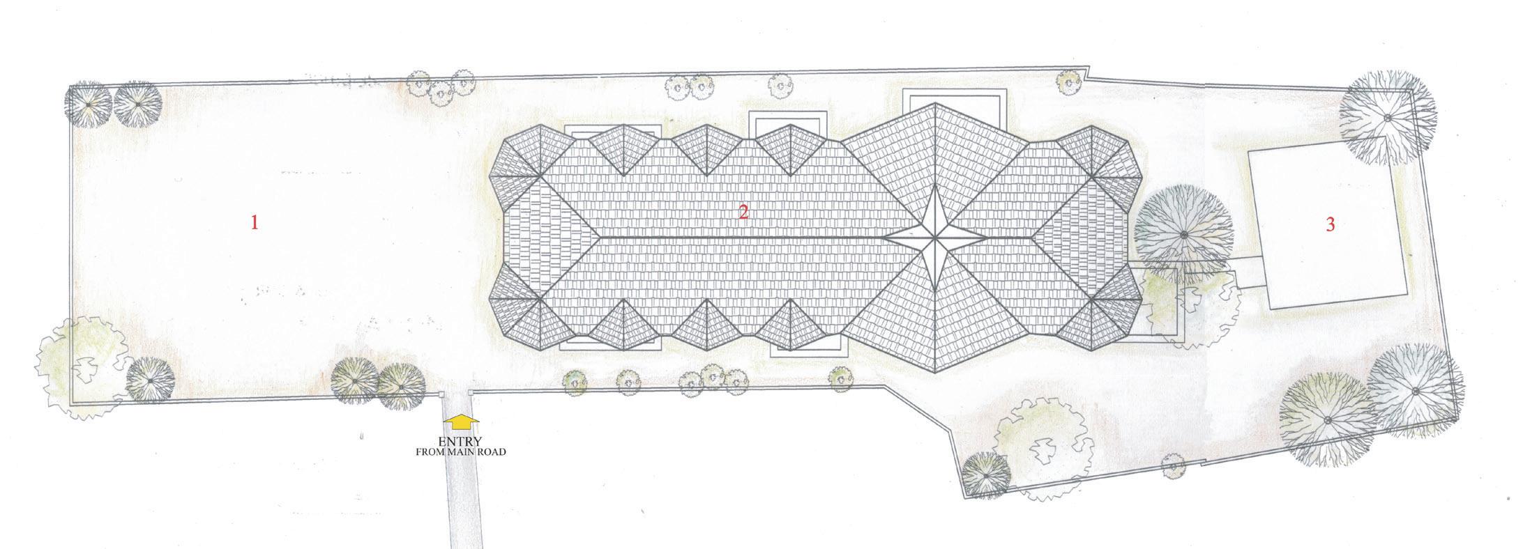
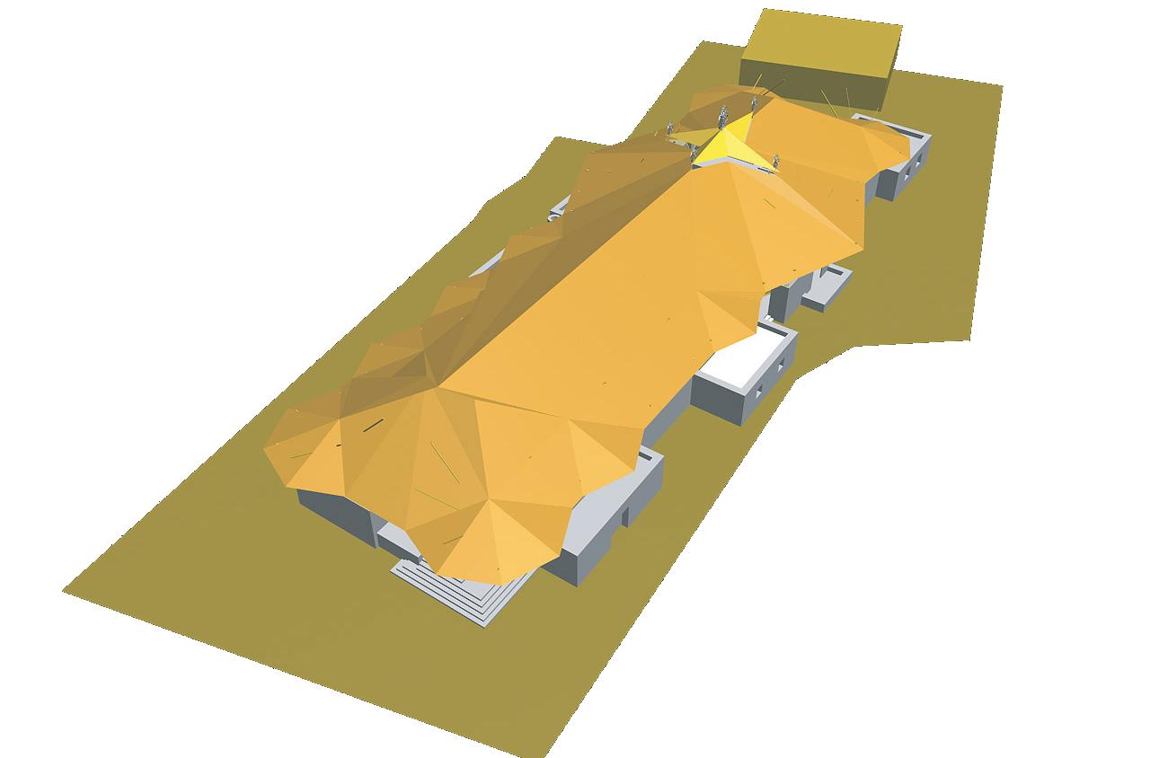
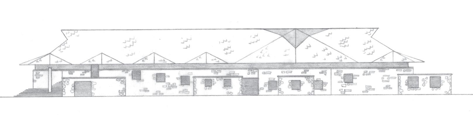
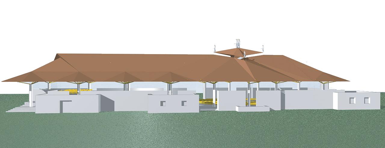
- The cathedral is an intimate public building, with a roof that repeats polygonal forms along its length. The entrance porch on the short side is made grand by the low masonry (grey basaltic granite) mass that it shelters, and which is part of the long side wall of the church.
- The factor to appreciate most about this project is the immense intricacy taken into account especially for the roofing details. Ar. Dean worked closely with the workers on site on many occasions to adapt and make changes as necessary.
- A blend of Portuguese and Indian influences, characterized by its whitewashed facade, intricate detailing, and ornate interior decorations.
- Consider the temporal dynamics of architecture, designing spaces that evolve over time and age gracefully, embracing impermanence and change as integral aspects of the architectural narrative.
41.
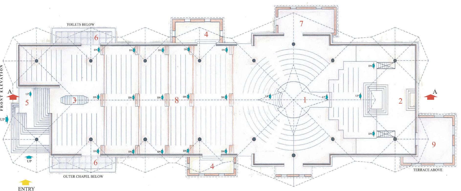
D3 K A R W A R C A T H E D R A L 1 2 3 4 E A S T E L E V A T O N S E C T I O N A-A 1 Sacr sty 2 B essed Sacrament 3 A tar 4 Bapt sma Font F L O O R P L A N 1 A tar 2 B essed Sacrament 3 Bapt smal Font 4 Chapel 5 En rance 6 Ba cony 7 Mus c Room 8 Centra Ha l 9 Vestry B B D2 K A R W A R C A T H E D R A L S E C T O N A L P L A N N 0m 1m 5m 10m 20m 1 Open Forecourt 2 Cathedral 3 Presby ery S I T E P L A N D1 K A R W A R C A T H E D R A L V I E W N m m 5 m m
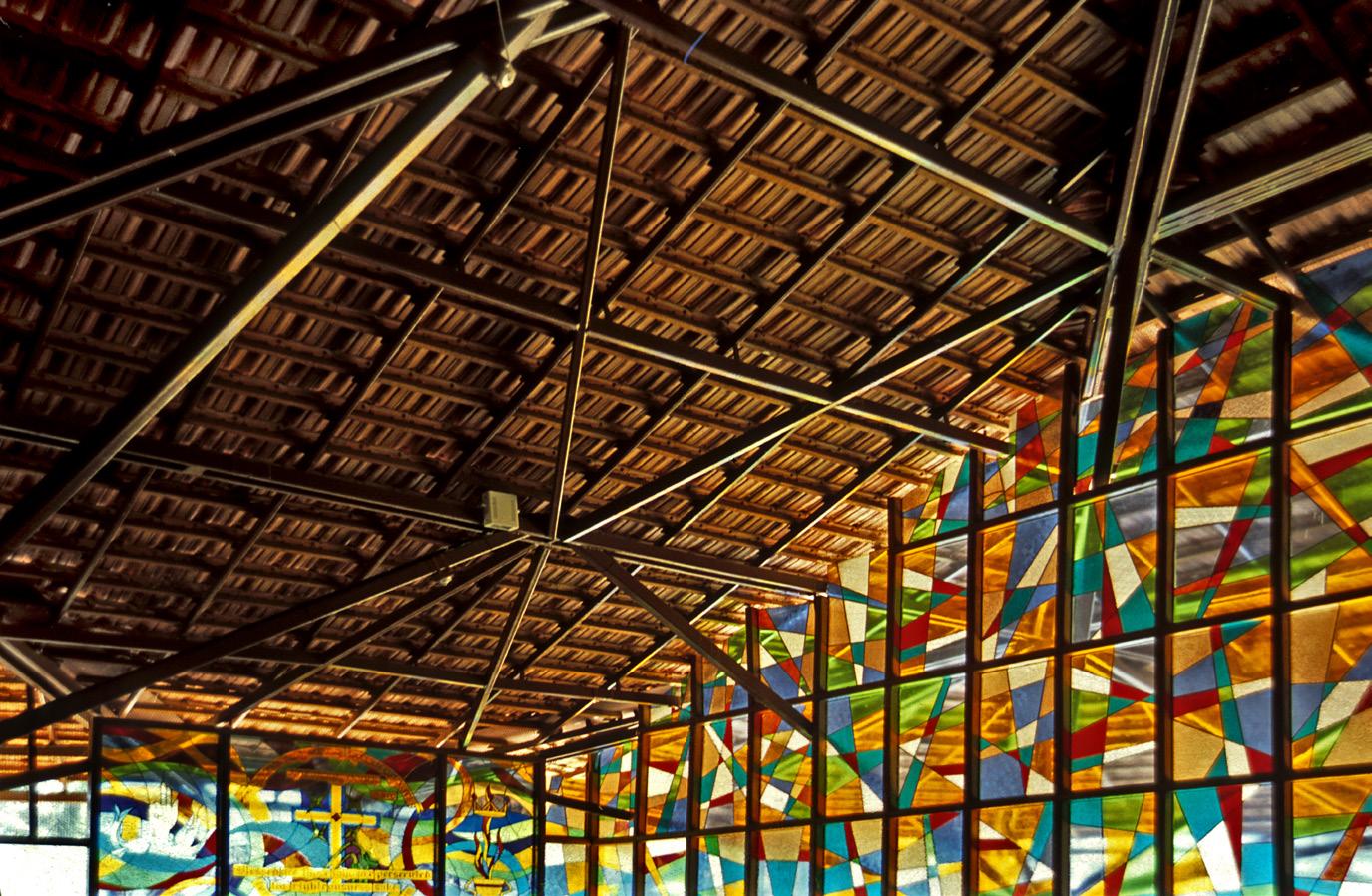
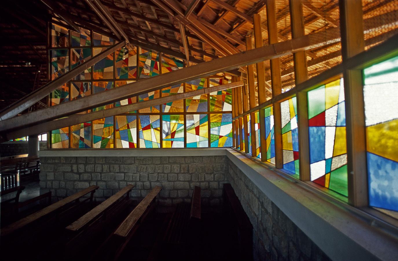
The stained glass panels were hand made individually with unique designs in each by the very nuns that are part of the church.
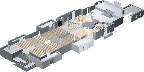
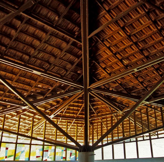
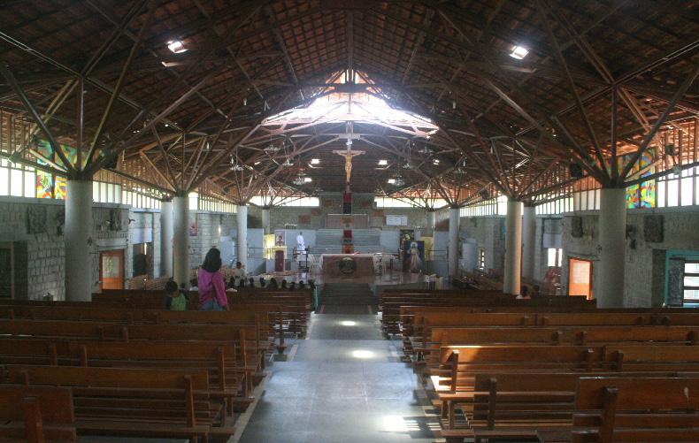
From either end of the cathedral, one gets this vast unhindered view from end to end with a rather majestic roof placed on top. The roof opens up at certain parts to facilitate lighting and ventilation.
Octagonal joists which support the rafters are placed on cylindrical columns across the cathedral as seen in the enlarged views on the right.
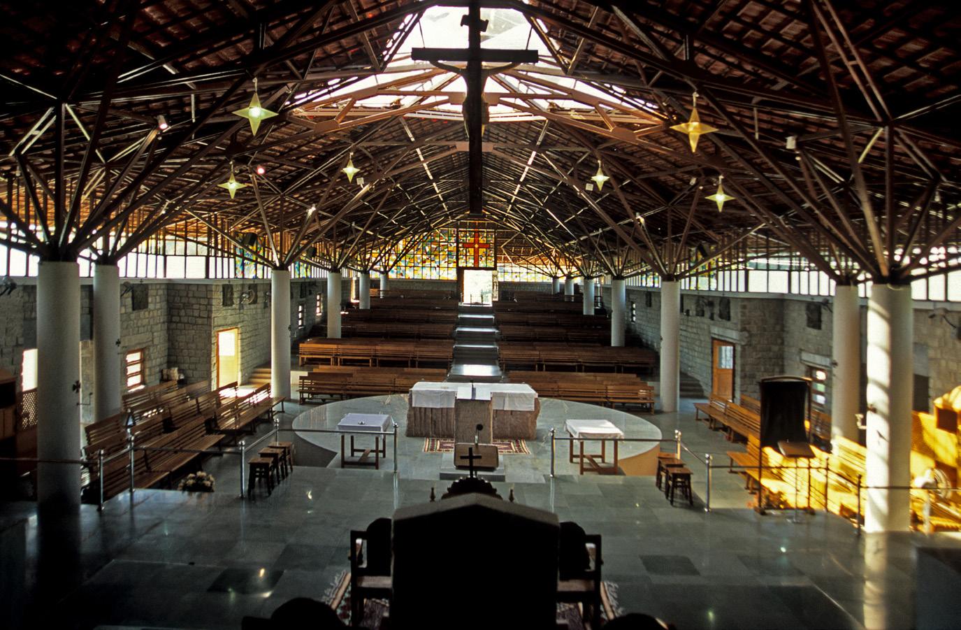
Built in 2012, a lot of the details and drawings were scrutinized on site. An unconventional church form, however, still preserves the verticality of space and emphasises it with the linear arrangement of said space which answers liturgical needs.
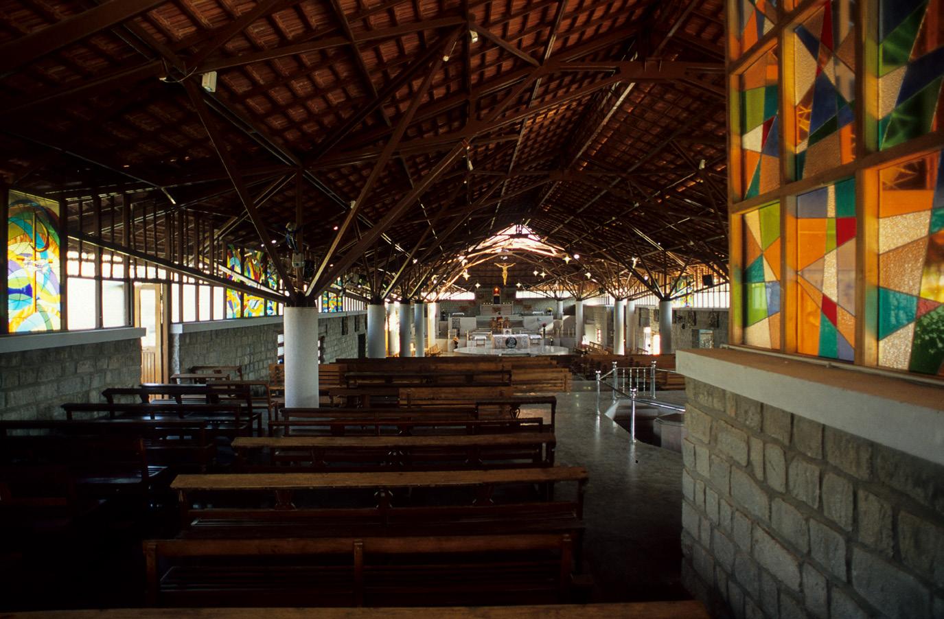
Almost gives a sense of Mangalore tiled roofs ‘floating’ over the solid masonry mass of a building
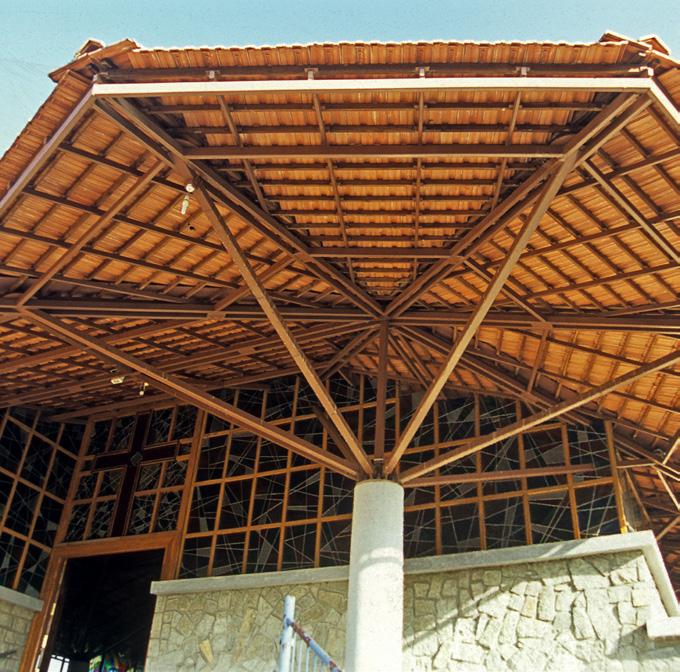
The porch has a dramatic single RCC column which sprouts ‘branches’ (mild steel box sections) that spread to the periphery of the octagonal-plan roof. This is a key element. Once we are inside the ‘tree’ is revealed as one of a ‘forest’ that holds up the entire roof in the interior.
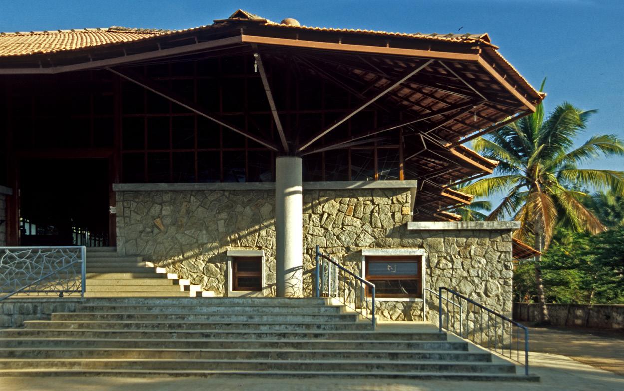
The entrance porch on the short side is made grand by the low masonry (grey basaltic granite) mass that it shelters, and which is part of the long side wall of the church.
The church is designed like a stepped auditorium to give the last row a good view of the rituals and the altar.
This is certainly unusual in comparison to other churches we see wherein an array of seating at a uniform level is provided.
The cathedral conducts masses of different sizes. The tiered arrangement allows for seating based on size of the mass.
This reflects the larger vision underlying the design: that public or religious institutional spaces can be dignified and intimate at the same time, and monumental without being overpowering.
42.
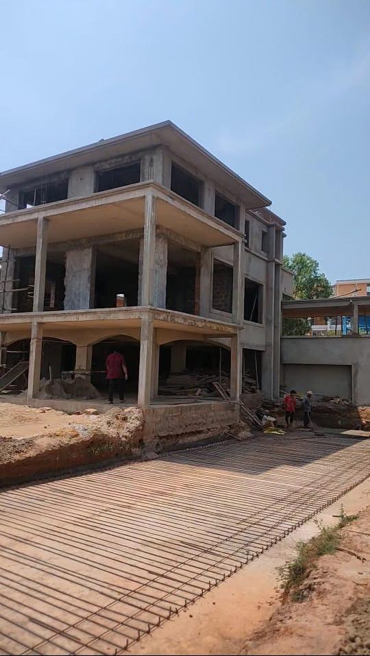
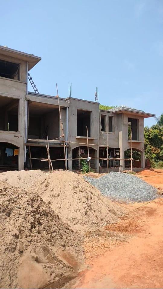
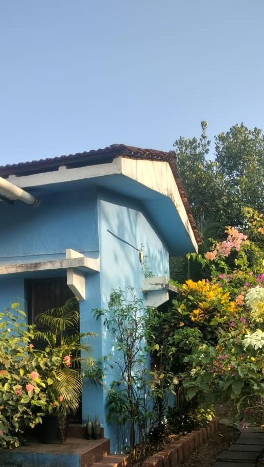
Site visits
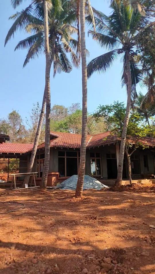
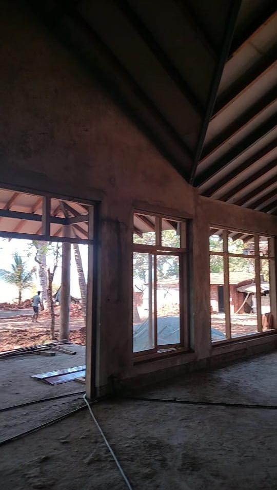
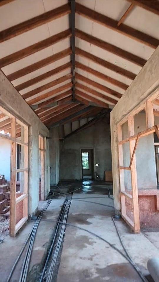
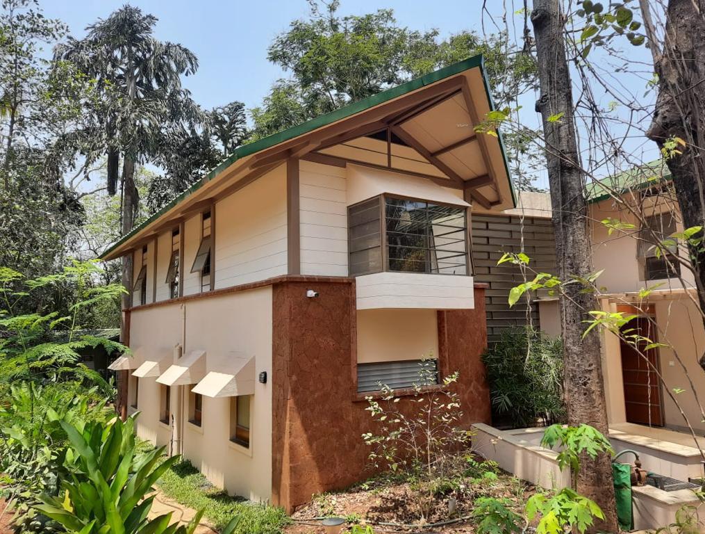
A serene, calm location on Diwar Islands almost completed with construction. Thatching on the roof just complete, interior finishes and door window fixtures remaining.
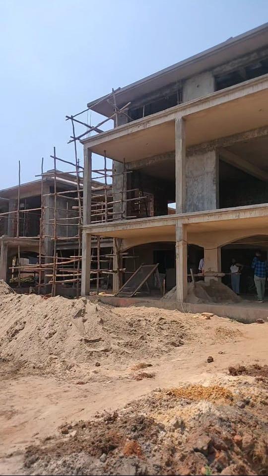
A three tier residence with the main house, guest house and staff quarters sits in a quiet yet lush locality in
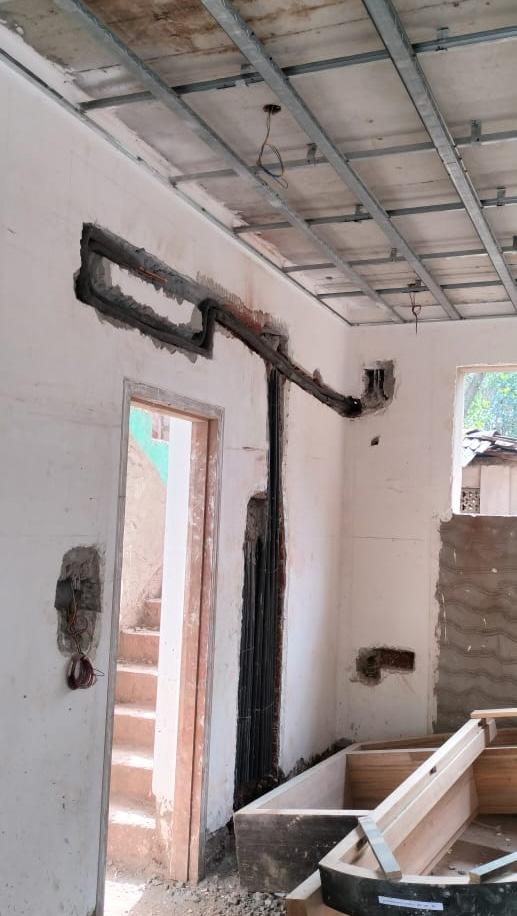
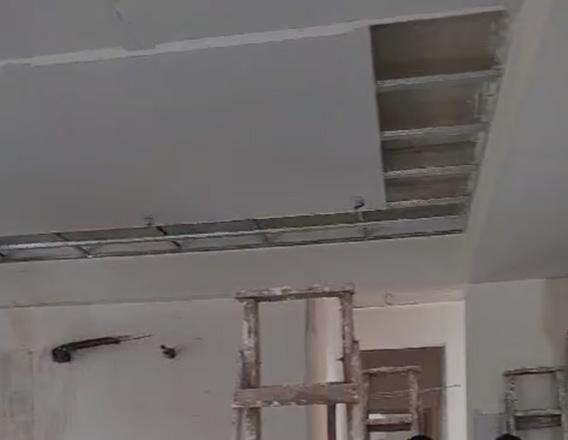
Conduits on the wall for wiring layouts for a seamless external finish. False ceiling panels placed for any fixtures and electricals on the ceiling.
Sunken slab details for the washrooms for a clean finish and easy flow of sewage
Polygonal forms repeat to give the roof form. Full length windows and doors open up the entire structure to the outside.
Passageway connecting two units. Conduits in place for the covered finish of all electric layouts. The finish to be administered with Jaisalmer stone.
43.
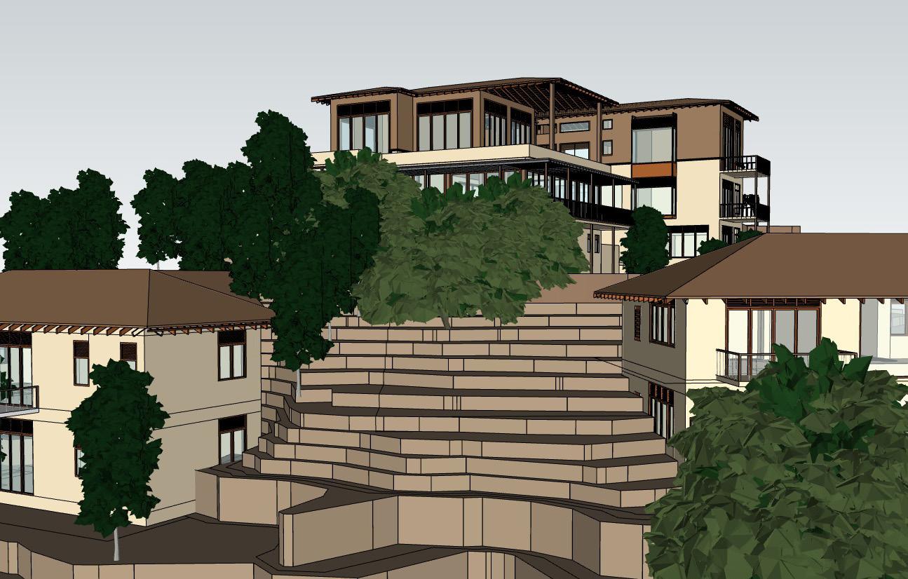
Arul Residence, Diwar Islands.
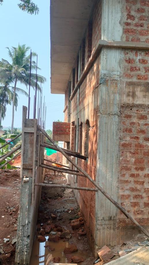
Carmona Villa, Goa.
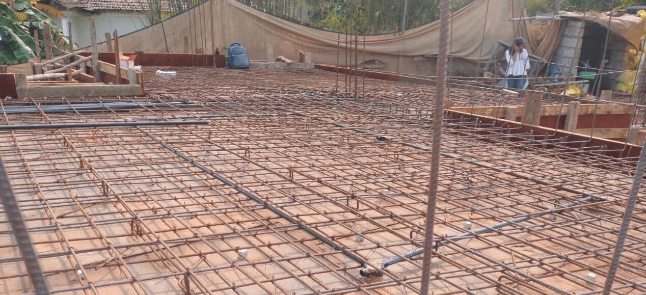
The two units are up to the 2nd floor slab level.
The panaroma from left to right shows the two units with the common lower ground floor, a connecting bridge and swimming pool that gives a sense of division between the two villas
Edwin Saldhana Residence, Goa.
Goa.
Measure Drawing
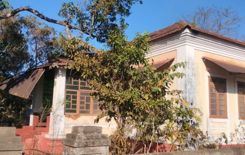
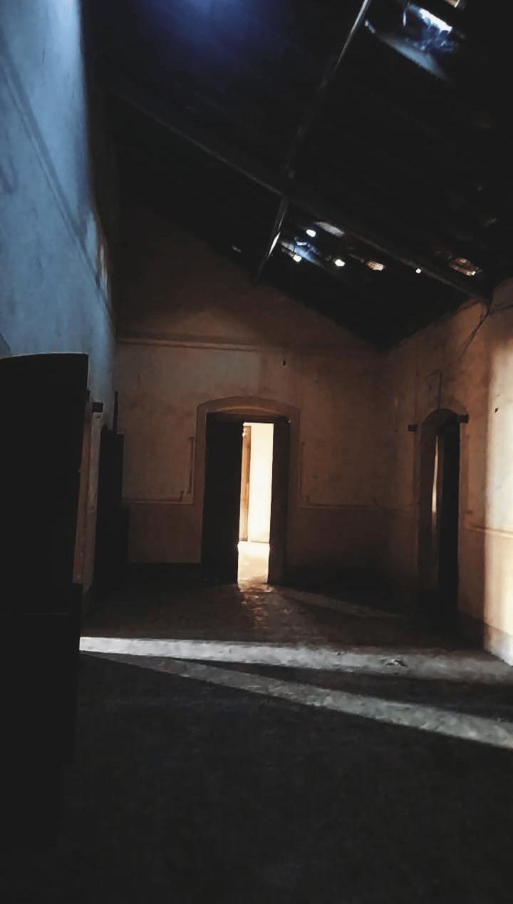
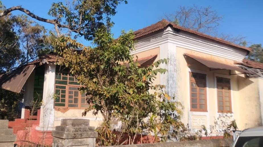
A beautiful portugese villa, extravagantly built about 200 years ago. Vast open spaces and huge openings for doors and windows made this measure drawing a laborious task but a rather interesting one.
The couple planning to move back from Canada want to revamp this family home still holding true to its Portugese style with a slight contemporary touch.
Andrea Residence, Defence Colony, Goa.
Measure Drawing
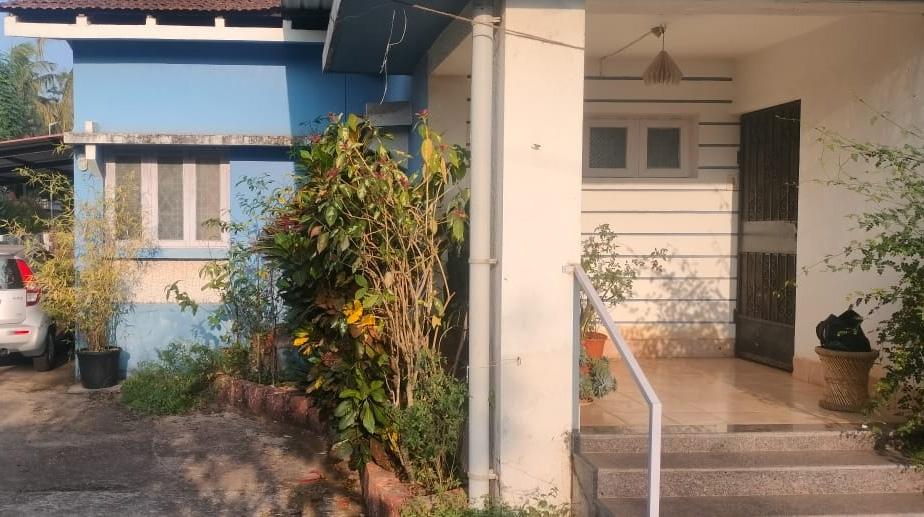
A tiring but fun experience where we had to measure draw an existing structure owned by Andrea in Defence Colony, Porvorim.
The couple are looking to expand their house to accomodate 2 more bedrooms possibly on an elevated level.
44.
Douglas Nazreth, Moira, Goa.
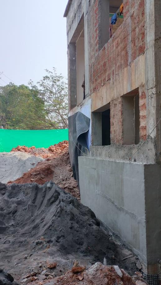
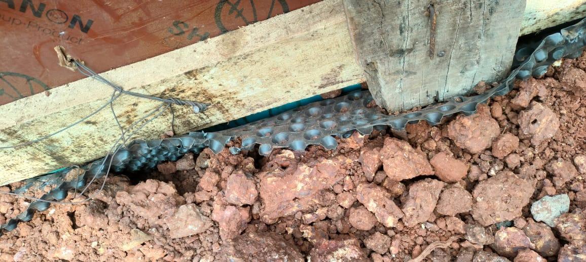
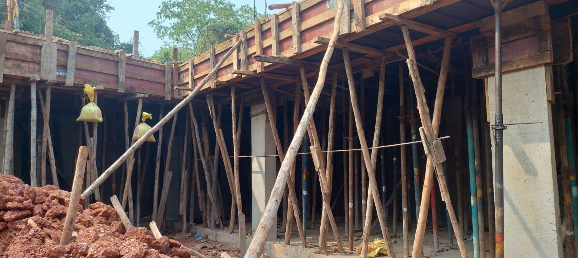
Spandhan Residence, Goa.
Membrane layer with porous like structure used as a waterproofing method in construction for this project.
This structure sits on a lower ground level with one end completely retained with the use of laterite stone.
A look at the roof slab holding all the wiring and electric layouts to give a seamless finish on the interiors of the building.