MiMode PuraBead® CX2 is a mixed-mode chromatography adsorbent, featuring a proprietary synthetic mixed-mode ligand. The ligand features cation exchange, hydrophobic, and hydrogen-bond interaction characteristics, making it a unique tool for purification of target biomolecules, both in bind-and-elute mode and flow-through polishing. MiMode PuraBead® CX2 is built on Astrea Bioseparations Ltd and its Affiliates (“Astrea Bioseparations”) PuraBead® 6HF base matrix, affording excellent packing robustness and high flow capabilities.
RECOMMENDED PACKING CONDITIONS: Pack at a constant pressure of up to 1. 2 bar
RECOMMENDED PACKING SOLUTION: 0.1 M NaCl solution
RECOMMENDED OPERATIONAL FLOW RATES: Up to 600 cm/h
OPERATING PH: pH 3.0 to pH 14.0
CHEMICAL STABILITY:
All commonly used aqueous buffers and co-solvents
CLEANING/SANITIZATION: 0.5 to 1.0 M NaOH
STERILIZATION:
STORAGE:
Autoclavable in 0.1 M NaCl solution at 121 °C for 30 minutes
2–30 °C, 20% ethanol : 80% 0.1 M NaCl
COLUMN PACKING
Th is resin is supplied in a preservative containing 20% ethano l : 80% 0.1 M NaCl . Before commencing the column pack, consult the relevant manufacturer’s instructions for the selected column hardware .
The method below describes the packing of Astrea Bioseparations’ MiMode PuraBead ® CX2 into axial 1 cm diameter columns with a 10 – 15 cm bed height .
Preparation of adsorbent slurry
1. Allow all materials to equilibrate to the temperature at which the chromatography process is to be performed.
2. Determine the % slurry of the resin by agitating the resin in the bottle to form a complete slurry. Pour out around 15 mL into an appropriate measuring cylinder or 1 cm diameter column. Leave to settle for a minimum of 2 hours. Calculate the % slurry:
Slurry % calculation:
3. Calculate the volume of slurry required. A compression factor (CF) of 1.18 (1.15–1.19) is recommended:
Column volume (CV) calculation:
Where ‘r’ is the radius of the column hardware in cm and ‘BH’ is the target bed height in cm.
Slurry volume (SV) calculation:
Where ‘CV’ is the column volume calculated above, ‘CF’ is the compression factor, and ‘slurry percentage’ is the slurry as calculated above.
4. Measure out the calculated volume of slurry required. Alternatively, the adsorbent can be settled to a given bed height range under drainage to obtain the required bed height without determining the percentage slurry (see step 8).
Column hardware preparation and transfer
5. Assemble the column and remove air from the dead spaces by flushing the end piece and adapter with storage solution (20% ethanol : 80% 0.1 M NaCl solution) then close the column outlet.
6. Carefully pour the measured resin slurry into the column. Pouring the slurry down the side of the column helps to prevent air becoming trapped within the resin bed Open the column outlet and allow the preservative to drain If the total volume of resin does not fit in the column on the first addition, add the remainder of the slurry before the slurry in the bed has completely settled. Rinse out the receptacle the resin was poured from with storage solution and add to the column when there is sufficient space.
7. A headspace will form between the resin bed and storage solution on settling under drainage. Seal the bottom of the column before all the storage solution flows through the bed.
8. If the slurry % was not determined, completely re-slurry the resin in the bottle and pour into the column. Unseal the bottom of the column and allow the resin to settle under drainage. Settle the resin to a bed height that allows for a compression factor (CF) of 1.14 (1.12–1.16) when packing:
Settled resin bed height calculation =
For example, if you require a 10 cm bed height you should settle to 11.4 cm:
9. If during this process the bed has completely settled, and you need to add more resin, slurry the top 0.5 cm of the bed (add storage solution if required) before adding the additional resin. Once the required bed height has been achieved, seal the bottom of the column. Throughout this process, ensure that all the storage solution does not enter the bed. Add more storage solution if required.
Packing the column
10. Attach the top adapter to the workstation and flush with packing solution. Fill the column with packing solution (0.1 M NaCl). Loosen the attachment of the top adapter to the workstation to allow liquid to flow out and carefully add the top adapter to the top of the column, avoiding the introduction of air bubbles. Adjust the adapter to the top of the bed (Note: Bed will drop as you insert the adapter), tighten the connection to the workstation, and tighten the adapter into place.
11. Open the column outlet and apply a packing flow rate that gives a stable pre-column pressure of up to 0.11 MPa after the first CV. Note: Due to the presence of ethanol in the column, the pressure will initially be higher for the first CV. This initial pressure is expected to be in the range of 0.14–0.18 MPa when packing at a stable pressure of 0.11 MPa ± 0.01 MPa. To avoid bed compression during operation, ensure that the packing pressure is higher than the operational pressure at the process step with the highest pre-
column pressure Aim for a maximum operational pressure of no greater than 75% of the column packing pressure.
12. Apply packing flow for around 10 CV Before stopping the flow rate, mark the bed height. Stop the liquid flow through the bed and seal the column outlet.
13. Lower the top adapter to the marked bed height by loosening the top adapter seal (the top adapter must allow free flow from the workstation either by loosening the top adapter connection or, if present, switching the top valve to waste).
Note: Once the flow is paused, the bed may relax and rise.
14. Re-tighten the top adapter (if loosened) and attach back to the workstation (or switch valve back in-line). Open the bottom outlet and apply the packing flow to the column again for at least 5 CV, ensuring the pre-column pressure does not exceed 0.13 MPa. If a space is formed between the top of the resin bed and the adapter, repeat the steps 11 and 12. If no space forms, the column is packed and ready to use.
COLUMN EFFICIENCY TEST
Test procedure
1. Attach the column packed according to the ‘Column Packing’ section above to a workstation primed with a mobile phase solution of 0.1 M NaCl or buffer of a conductivity of at least 6 mS/cm
2. Commence flow of mobile phase at 75 cm/h for at least 1 CV ensuring that the column is equilibrated with the mobile phase and a baseline obtained.
3. Inject 2% CV of a 1 M NaCl solution.
4. Continue flow until a conductivity peak is observed, and the trace has returned to baseline (≥1.5 CV).
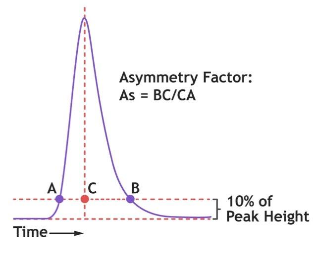
Asymmetry determination
Determine the asymmetry (As) factor as follows: �������� = �������� ��������
Where ‘BC’ is the peak tail width at 10% peak height and ‘CA’ is the peak front width at 10% peak height.
A typical acceptable range for asymmetry factor for packed resin is between 0.8 to 1.8, but the required range should be qualified to each process/application.
Asymmetry trouble shooting
As >1.8 (tailing) indicates that the column is underpacked. For asymmetry values significantly above 1.8, aim for a higher compression factor by targeting a higher packing pressure.
As <0.8 (fronting) indicates that the column is overpacked For asymmetry values significantly below 0.8, target a lower compression factor by targeting a lower packing pressure.
Efficiency (HETP) determination
Determine the efficiency ( HETP) and theoretical plates (N) values as follows:
Theoretical plates (N) value is a measure of the peak broadening and can be used to determine the column efficiency. The higher the plates value, the less dispersion and the more efficient peaks and separation. The plates (N) value is calculated by:
Where ‘VR’ is the retention volume and ‘Wh’ is the peak width at half of the peak height.
HETP (H) is used to determine the column efficiency and corresponds to the distance between each plate. HETP is calculated by:
Where ‘L’ is the length of the column (bed height), and ‘N’ is the number of theoretical plates (as calculated above).
Plate count range required for the column should be verified for each process/application. The typical theoretical plates per meter count for an acceptable pack is ≥2000 N/m.
HETP trouble shooting
If the calculated plates/meter value is significantly below 2000 N/m repack the column and repeat column efficiency testing.
The lower the HETP value (the higher the plate number), the more efficient the column is. When measured over time, the HETP can be used to monitor the column performance. If the HETP value increases this indicates a reduction in the column performance and the column should be repacked.
OPERATING INSTRUCTIONS
Note: The following recommendations are not prescriptive and a thorough investigation of these parameters at small-scale should be conducted to reveal the level of flexibility that can be tolerated with the chromatography resin, buffer, and protein combination selected. MiMode PuraBead® CX2 column kits are also available for screening experiments.
The following method is recommended as a starting point using a small-scale column, such as a 6–10 cm bed height, 0.5–1 cm diameter column, and using an initial flow rate which gives a 5-minute residence time for the column chromatography steps. Subsequent increases/decreases in the flow rate can be investigated to improve binding capacity or decrease processing times. Do not exceed an operational flow rate of more than 75% of the column packing flow rate. The following method assumes at least a 5 mL column volume; if a smaller column volume is used, the CV for each of the steps may need to be increased.
Note: Sulphate and sulphonate buffers such as MES and HEPES are expected to interfere with binding to the column. It is recommended to avoid sulphate/sulphonate buffers in the equilibration and feedstock in the first instance. If it is desired to use theses buffers, the effects should be qualified on a small scale for the process in question.
Filter all buffers and feedstock through an appropriate filter, prior to running the column.
1. Equilibration
Equilibration buffer should match the feedstock as closely as possible However, the feedstock buffer may need to be adjusted to allow target binding to the column. Equilibration conditions are expected to be around neutral pH The pH should be below the isoelectric point (pI) of the target (ideally by 1 pH unit, but at least 0.5 units). A buffer with buffering capacity at the selected pH should be selected. A physiological conductivity is a recommended starting point.
Equilibrate the column with up to 5 CV of equilibration buffer.
2. Load and post-load wash
Adjust the feedstock pH and conductivity to match the equilibration buffer if required. Apply the clarified/filtered feedstock onto the equilibrated column. Recommended residence time is 5 minutes.
Remove any non-bound material from the column with up to 5 CV of equilibration buffer, or until the UV trace returns to baseline.
3. Elution
Elute the bound protein by adding up to 2 M NaCl to the equilibration buffer, elute for up to 5 CV or when the UV has returned to baseline with elution buffer. Follow with a strip condition (suggested strip for primary investigation: equilibration buffer +10% hexanediol, 1 M NaCl) for 5 CV or when UV has returned to baseline.
4. Cleaning and sanitization
A clean-in-place (CIP) step is recommended to avoid buildup of process impurities over multiple cycles. This maintains column efficiency, capacity, and separation performance.
If a CIP is required, use up to 5 CV of 0.5 to 1.0 M NaOH. A contact time of 1 hour will normally suffice to ensure destruction of viable organisms, although up to 5 hours contact time may be required. No less than 5 column volumes are recommended.
When a more intensive cleaning cycle is required, the following are recommended:
• If lipid fouling is a major issue, use 30%–40% isopropanol in combination with NaOH
• If iron and calcium fouling is an issue, use 50% citric acid.
• If aggregated/precipitated proteins are an issue or a crude lysate feedstock has been loaded onto the column, wash the resin with either 8 M urea or 6 M guanidine- HCl.
• Acid base cycling of: 1 M NaOH, 1 M acetic acid, 1 M NaOH, 1 M acetic acid.
Re-equilibrate column with up to 5 CV of equilibration buffer (to remove sodium hydroxide or neutralize the resin) and check that the pH and conductivity of the column eluate is equal to that of the buffer entering the column before storage or re-use.
5. Storage
If the column is to be stored for future use, place the column into the storage solution (20% ethanol, 80% 0.1 M NaCl is recommended; 0.01 M NaOH acceptable for short-term storage up to 1 week) and store at 2–30 °C.
6. Optimization
pH and conductivity elution gradients
MiMode PuraBead® CX2 is a mixed-mode ligand, which while showing preferential binding to botulinum toxin, has the potential to bind other proteins under certain conditions
It is therefore expected that optimization of the buffer conditions is required to gain good elution purity. Recommendations for the first experiments for optimization is to run a series of gradient elutions.
When running the gradient , a 10 cm bed height column is recommended as well as an asymmetry of 0.8–1.2. Elution gradients should be performed over 20–40 CVs.
1. NaCl gradient: From equilibration buffer to equilibration buffer with 2 M NaCl.
2. Decreasing pH: From equilibration pH to pH 3 or the lowest pH the target is stable at.
3. Increasing pH: From the equilibration pH up to pH 9 or the highest pH the target is stable.
Note: For the pH gradients , select a buffer which will buffer across the pH range being investigated. If this differs from the buffer used for equilibration, it is recommended to wash the column into the new buffer at the pH at which the gradient will start, prior to starting the gradient, to see if the buffer change causes any elution from the column.
Results from the gradient runs should be looked at to see where optimal target protein elution is achieved. In addition to this, identifying where non-target proteins elute prior to the target is of interest. This allows identification of possible wash steps which can be introduced to improve elution purity.
Once points on the gradient yielding good potential wash or elution conditions have been identified, these should be tested under step conditions. For example, if on a NaCl gradient, there is a non-target peak at 20 mS/cm and the target protein elutes at 62 mS/cm, a wash at 25 mS/cm for 5 CV could be introduced. This could be followed by a step elution for 5–10 CV at 62–70 mS/cm (lower end if non-target is eluting closely after, higher end to maximize recovery; this may require fine tuning for optimal results).
Results from the gradient elution will give possible steps to try to achieve the required purity and recovery. If this is not achieved, further screening is required. The results from the gradients could be used to identify areas for further screening of wash and/or elution conditions by combining the effects of pH and NaCl.
Elution additives
Alternatively, the addition of additives could also be investigated, such as (but not limited to) low concentration Tween 20 or 80, low concentration glycerol, low concentration high and low molecular weight PEGs, sodium cholate, arginine, hight concentration MES, or high concentration HEPEs.
Binding capacity optimization
If binding capacities require improving, it is recommended to ensure the buffer compatibility of the equilibration buffer and the feedstock with the column (no sulphate or sulphonated buffer components or additives). Other areas to investigate are pH and conductivity of the equilibration buffer and feedstock, as well as increasing residence time.
ORDER INFORMATION
Gel slurry
Code Description
FG00677-00025 MiMode PuraBead® CX2
FG00677-00100 MiMode PuraBead® CX2
mL
mL
FG00677-00500 MiMode PuraBead® CX2 500 mL
FG00677-01000 MiMode PuraBead® CX2 1 Liter
Astrea Bioseparations also supplies larger volumes of bulk resins for cGMP development and manufacturing-scale processes.
Pre-packed formats
MiMode PuraBead® CX2 is available in a range of pre-packed formats.
Code Description
FG00679 MiMode PuraBead® CX2, 4 X 1 mL HT columns
FG00680 MiMode PuraBead® CX2, 4 X 5 mL HT columns
FG00681 MiMode PuraBead® CX2, 1 X 1 mL HT columns
FG00682 MiMode PuraBead® CX2, 1 X 5 mL HT columns
FG00693 MiMode PuraBead® CX2, 96-well plate
FG00698 MiMode PuraBead® CX2, 200 µL RoboColumn®
FG00715 MiMode PuraBead® CX2, 600 µL RoboColumn®
In addition, Astrea Bioseparations can offer column packing services. For more information on this or any other supply related matters, please do not hesitate to contact us at sales@astreabio.com.