PRECAST MODULAR BLOCK
DESIGN MANUAL VOL. 1 GRAVITY WALLS
 Jamie Johnson Nils Lindwall
Clint Hines
Jamie Johnson Nils Lindwall
Clint Hines
The data and materials contained in the Precast Modular Block Design Manual Volume 1: Gravity Walls (Design Manual) have been compiled by Aster Brands and the authors, and are presented in this Design Manual for general information only. The information contained herein should not be used or relied upon for specific applications without competent professional verification of the applicability of such information relative to any general or specific application. Any person or entity making use of the material herein does so at their own risk and assumes all liability resulting from such use.
ASTER BRANDS AND THE AUTHORS EXPRESSLY DISCLAIM ANY WARRANTY, EXPRESS OR IMPLIED, RELATED TO THE INFORMATION AND MATERIALS PROVIDED OR REFERENCED HEREIN. Nothing herein contained shall be construed as granting a license, express or implied, under any patents. The contents of this Design Manual, including but not limited to the text and images herein and their arrangements, unless otherwise noted, are the copyrighted material of Aster Brands. Copyright © 2022 Aster Brands. All rights reserved. All Trademarks referred to are the property of their respective owners.
Aster Brands is a DBA of Redi-Rock International, L.L.C. of Charlevoix, Michigan USA.
ii PRECAST MODULAR BLOCK DESIGN MANUAL VOLUME 1: GRAVITY WALLS
PRECAST MODULAR BLOCK
Design Manual Volume 1: Gravity Walls
In U.S. Customary & Metric units
Authors - Jamie Johnson, Nils Lindwall, John Clinton Hines
Copy Editor - Keith Carey Graphic Designer - Greg Manning
iii PRECAST MODULAR BLOCK DESIGN MANUAL VOLUME 1: GRAVITY WALLS
TABLE OF CONTENTS
CHAPTER 1.0 INTRODUCTION
1.1. Introduction and Purpose
What is a Precast Modular Block?
1.3. Benefits of PMB Walls
Typical Gravity Retaining Wall with PMB Units
CHAPTER 2.0 DESIGN INPUTS
2.1. Where to Start
2.1.1. Typical Steps for Design and Construction of a Wall
Project Team
Information Required to Design a Wall. . . . . . . . . . . . . . . . . . . . . . . . . . . . .
2.2. PMB Unit Properties . . . . . . . . . . . . . . . . . . . . . . . . . . . . . . . . . . . . . . . . . . . . . . . . . . .
2.2.1. Size
Unit Weight
2.2.3. Block-to-Block Interface Shear. . . . . . . . . . . . . . . . . . . . . . . . . . . . . . . . . .
2.3. Soils . . . . . . . . . . . . . . . . . . . . . . . . . . . . . . . . . . . . . . . . . . . . . . . .
Classification
Strength
2.3.3. Unit Weight, Density, and Compaction
Soils Types and Walls
Wall Geometry
Batter
Embedment
2.4.3. Tiered Wall Construction
CHAPTER 3.0 LOADS ON THE WALL
3.1. Overview of Stabilizing and Destabilizing Forces
3.2. Determination of Earth Pressure Acting on a Wall
3.2.1. Equivalent Fluid Pressure
3.2.2. Earth Pressure Coefficients
Plane Theories
3.2.3.1. Rankine Earth Pressure Theory
3.2.3.2. Coulomb Earth Pressure Theory
iv PRECAST MODULAR BLOCK DESIGN MANUAL VOLUME 1: GRAVITY WALLS
. . . . . . . . . . . . . . . . . . . . . . . . . . . . . . . . . . . . . . . . . . . . . . . . 1 1.2.
. . . . . . . . . . . . . . . . . . . . . . . . . . . . . . . . . . . . . . . 3
6 1.4.
8 1.5 References . . . . . . . . . . . . . . . . . . . . . . . . . . . . . . . . . . . . . . . . . . . . . . . . . . . . . . . . . . . . . . 10
. . . . . . . . . . . . . . . . . . . . . . . . . . . . . . . . . . . . . . . . . . . . . . . . . . . . . . . . . . . 13
13 2.1.2.
15 2.1.3.
. 15
. . 17
17 2.2.2. Infilled
17
. . 18
. . . . . . . . . . . . . . . . . . . . . 19 2.3.1. Soil
19 2.3.2. Shear
. . . . . . . . . . . . . . . . . . . . . . . . . . . . . . . . . . . . . . . . . . . . . . . . 19
. . . . . . . . . . . . . . . . . . . . . . . . . . . . . . 22 2.3.4.
23 2.4.
25 2.4.1.
. . . . . . . . . . . . . . . . . . . . . . . . . . . . . . . . . . . . . . . . . . . . . . . . . . . . . . . 26 2.4.2.
. . . . . . . . . . . . . . . . . . . . . . . . . . . . . . . . . . . . . . . . . . . . . . . . . . 27
28
31
32
. . . . . . . . . . . . . . . . . . . . . . . . . . . . . . . . . . . . . . . 32
34 3.2.3. Failure
35
. . . . . . . . . . . . . . . . . . . . . . . . . . . . . . . . . . . 36
. . . . . . . . . . . . . . . . . . . . . . . . . . . . . . . . . . 37
3.2.3.3. Log Spiral Earth Pressure Theory
3.2.3.4. General Limit Equilibrium
3.2.4. At-Rest Earth Pressure
3.2.5. Earth Pressure for This Manual
3.2.6. Back-of-Wall Location
3.2.6.1. Constant Batter Walls
3.2.6.2. AASHTO Stepped Modules
3.2.6.3. Skewed Back of Wall
3.3. Surcharge Loads
. . .
3.3.1. Uniform Loads . . . . . . . . . . . . . . . . . . . . . . . . . . . . . . . . . . . . . . . . . . . . . . . .
3.3.2. Offset Loads
3.4. Hydrostatic Loads 55
3.5. Seismic Loads . . . . . . . . . . . . . . . . . . . . . . . . . . . . . . . . . . . . . . . . . . . . . . . . . . . . . . . . . . .
3.6. Barrier Loads . . . . . . . . . . . . . . . . . . . . . . . . . . . . . . . . . . . . . . . . . . . . . . . . . . . . . . . . . . . .
3.6.1. Pedestrian Handrail Loads
3.6.2. Fences . . . . . . . . . . . . . . . . . . . . . . . . . . . . . . . . . . . . . . . . . . . . . . . . . . . .
3.6.3. Post-and-Beam Guardrails. . . . . . . . . . . . . . . . . . . . . . . . . . . . . . . . . . . .
3.6.4. Traffic Barriers for Highways
3.6.5. Traffic Barriers for Buildings and Other Structures
CHAPTER 4.0 STABILITY ANALYSIS
CHAPTER 5.0 DETAILING
v PRECAST MODULAR BLOCK DESIGN MANUAL VOLUME 1: GRAVITY WALLS
41
. . . . . . . . . . . . . . . . . . . . . . . . . . . . . . . . . . . . . . . . 42
43
44
. . . . . . . . . . . . . . . . . . . . . . . . . . . . . . . . . . . . . . . . . . 44
. . . . . . . . . . . . . . . . . . . . . . . . . . . . . . . . . . . . . . . . . . . 45
46
47
. . . . . . . . . . . . . . . . . . . . . . . . . . . . . . . . . . . . . . . . . . . . . . . . . . . . .
53
53
54
57
57
57
. . 57
. . . 57
58
58
4.1. Modes of Failure 61 4.2. Allowable Stress Design and Load and Resistance Factor Design . . . . . . . . . . . . . . . . . . . . . . . . . . . . . . . . . . . . . . . . . . . . . . . . . . . . . . . . . . . . . . . . . . . 63 4.3. External Sliding Stability 65 4.3.1. Resistance Against Sliding for Cohesionless Soils 68 4.3.2. Resistance Against Sliding for Soils with Cohesion . . . . . . . . . . . . . . . . . . . . 70 4.3.3. Resistance of the Soil in Front of the PMB Wall 70 4.4. External Overturning Stability 70 4.5. Eccentricity . . . . . . . . . . . . . . . . . . . . . . . . . . . . . . . . . . . . . . . . . . . . . . . . . . . . . . . . . . . . . . 73 4.6. Bearing Capacity . . . . . . . . . . . . . . . . . . . . . . . . . . . . . . . . . . . . . . . . . . . . . . . . . . . . . . . . 75 4.7. Settlement 79 4.8. Internal Stability 79 4.8.1. Sliding . . . . . . . . . . . . . . . . . . . . . . . . . . . . . . . . . . . . . . . . . . . . . . . . . . . . . . 80 4.8.2. Overturning 81 4.9. Global Stability and Internal Compound Stability 82
5.1. Overview 83
5.2. Running Bond
5.3. Leveling Pad
5.4. Drains 85
5.5. Slopes 86
5.5.1. Sloping Grade Parallel to Wall
5.5.2. Sloping Grade Perpendicular to Wall 88
5.6. Barriers 89
5.6.1. Rails and Fences
5.6.2. Traffic Barriers
. . . . . . . . . . . . . . . . . . . . . . . . . . . . . . . . . . . .
5.6.2.1. Post-and-Beam Guardrail
5.6.2.2. Concrete Parapet Wall with Moment Slab
5.6.2.3. Parapet Walls and Moment Slab that Incorporate PMB Units . . . . . . . . . . .
5.7. Curves and Corners . . . . . . . . . . . . . . . . . . . . . . . . . . . . . . . . . . . . . . . . . . . . . . . . . . . . . 94
5.7.1. Curves 94
5.7.2. Corners 96
5.8. Utilities and Culverts . . . . . . . . . . . . . . . . . . . . . . . . . . . . . . . . . . . . . . . . . . . . . . . . . . . . 97
5.8.1. Dry Utilities
Utilities
Installed Through the Wall
Culvert Headwalls
Vertical Slip Joint
Construction Tolerances
Wall Tolerances
Unit Tolerances
Maximum Joint Width
6.0 BEST PRACTICES
vi PRECAST MODULAR BLOCK DESIGN MANUAL VOLUME 1: GRAVITY WALLS
. . . . . . . . . . . . . . . . . . . . . . . . . . . . . . . . . . . . . . . . . . . . . . . . . . . . . . . . . . . 83
. . . . . . . . . . . . . . . . . . . . . . . . . . . . . . . . . . . . . . . . . . . . . . . . . . . . . . . . . . . . 84
. . . . . . . . . . . . . . . . . . . . . . . . . . . . . . . . . . . . 86
. . . . . . . . . . . . . . . . . . . . . . . . . . . . . . . . . . . . . . . . . . . . . 90
. . . . . . . . . . .
. 91
91
92
93
97 5.8.2. Wet
98 5.8.3. Pipes
. . . . . . . . . . . . . . . . . . . . . . . . . . . . . . . . . . 99 5.8.4.
. . . . . . . . . . . . . . . . . . . . . . . . . . . . . . . . . . . . . . . . . . . . 100 5.8.5.
102 5.9.
102 5.9.1.
. . . . . . . . . . . . . . . . . . . . . . . . . . . . . . . . . . . . . . . . . . . . . . 102 5.9.2. PMB
102 5.10.
103 CHAPTER
6.1. Geotechnical Site Investigation 105 6.2. Design Parameters 106 6.3. Site Grading, Alignment, and Utilities . . . . . . . . . . . . . . . . . . . . . . . . . . . . . . . . . . 106 6.4. Cost Estimating 108 6.5. Selecting a Retaining Wall Design Engineer 109 6.6. Engineering Design . . . . . . . . . . . . . . . . . . . . . . . . . . . . . . . . . . . . . . . . . . . . . . . . . . . . 111 6.7. Construction . . . . . . . . . . . . . . . . . . . . . . . . . . . . . . . . . . . . . . . . . . . . . . . . . . . . . . . . . . . 112 APPENDIX: A EXAMPLES 1-3 (U.S. CUSTOMARY UNITS) APPENDIX: B EXAMPLES 1-3 (METRIC UNITS) APPENDIX: C GRAPHICAL COULOMB SOLUTION
CHAPTER 1.0 INTRODUCTION
1.1.
INTRODUCTION AND PURPOSE
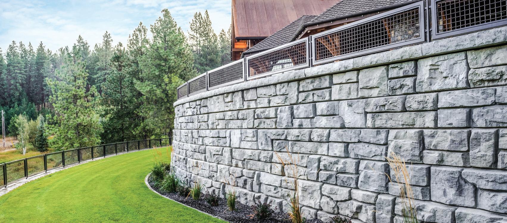
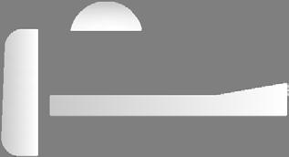
Big blocks have been used to construct walls for millennia. There is something inherently simple about stacking large blocks on top of each other that just makes sense. If the blocks are big and heavy enough, they can be used to safely support retained earth and anything else that might be on top of the wall. An example is shown in figure 1.1.

Fig. 1.1. Large block retaining wall.
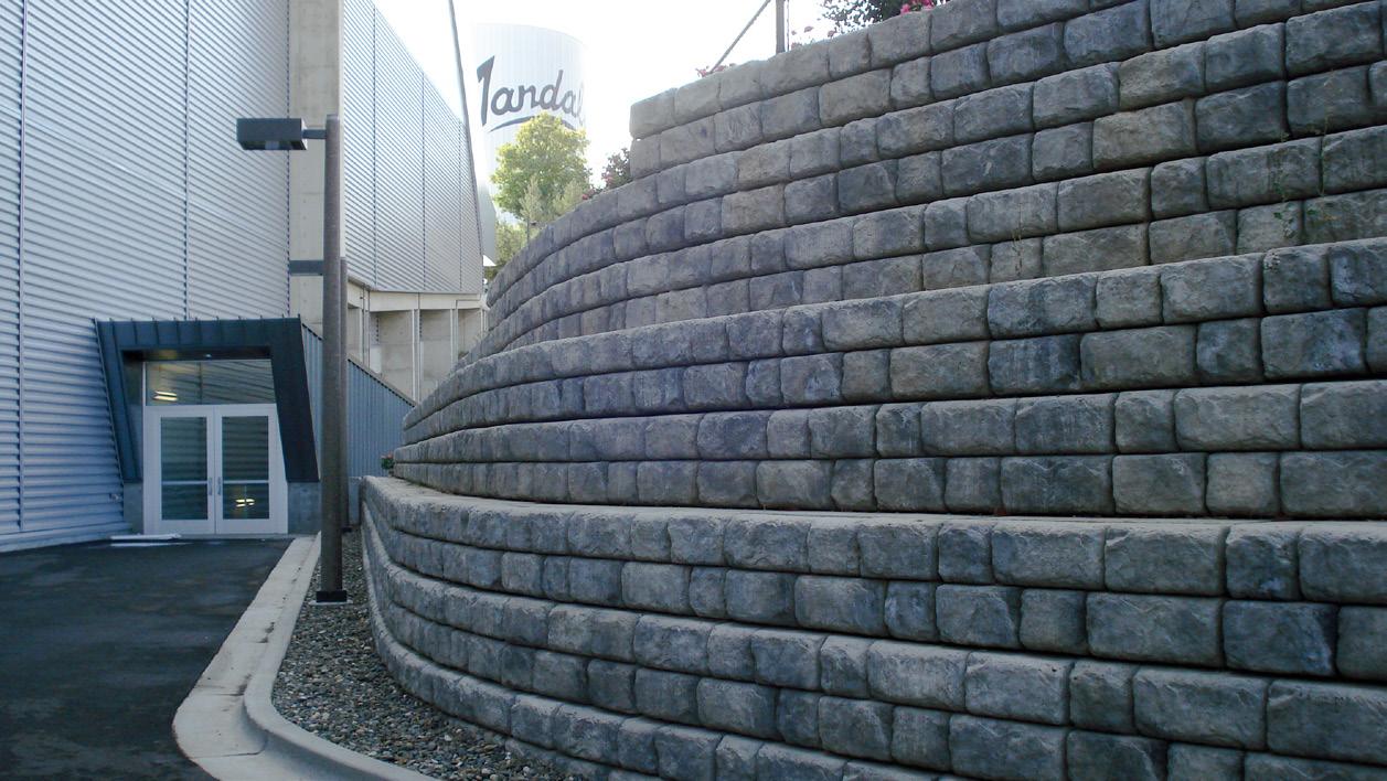
Relatively recently large precast concrete blocks, often called precast modular blocks or PMBs, have become widely available and are used to build retaining wall structures. PMB walls have been used in several innovative ways, such as constructing traditional walls, walls with large batter angles, PMB-faced mechanically stabilized earth structures, PMB-faced soil anchor walls, and freestanding walls that act as fences or barriers. PMB units are used in public agency projects, governmental projects, commercial projects, housing developments, and at private residences. Example walls are shown in Figures 1.2 and 1.3.
1INTRODUCTION PRECAST MODULAR BLOCK DESIGN MANUAL VOLUME 1: GRAVITY WALLS
Fig. 1.2. Example PMB wall.
Fig. 1.3. Example PMB residential wall.
The authors have decades of experience in the creation, testing, support, and design of precast modular block walls. Collectively, we have created new PMB units, performed extensive fullscale laboratory testing of PMB units, prepared design resources for PMB systems, provided technical consulting for engineers designing with PMB units, and been the design engineer of record for several signature PMB wall projects.
Sometimes engineers are reluctant to design PMB structures, acting on the incorrect assumption that PMB walls are somehow proprietary and can only be designed by the PMB manufacturers,


2 INTRODUCTION PRECAST MODULAR BLOCK DESIGN MANUAL VOLUME 1: GRAVITY WALLS
or they may simply not know where to start. This is unfortunate as the design of PMB walls is a direct application of widely accepted engineering principles for retaining walls that can be performed by anyone with a detailed understanding of how to correctly apply these principles. Textbooks, public agency documents (Federal Highway Administration, American Association of State Highway Transportation Agencies, etc.) and other general resources are available for the design of retaining walls. However, no single reference specifically focuses on PMB walls. Based on our decades of experience, the authors have attempted to collate general information into a design manual to help wall designers understand and apply firmly established engineering principles to PMB walls.
Even though the basic concepts are simple and PMB retaining walls are easy to construct, the engineers who design them are quite unique. They must possess a wide range of skills including a firm grasp of geotechnical engineering principles, a good working knowledge of structural engineering, an understanding of site engineering, and a strong background in construction. As such, this design manual assumes a working knowledge of soil mechanics, retaining wall design, and site design considerations like grading and utility design. This publication builds on these fundamentals and demonstrates how the related engineering principles are applied to PMB walls. Furthermore, while this design manual attempts to summarize the concepts and calculations associated with gravity PMB retaining walls, it is not intended to be a soil mechanics book. Rather it is intended as a workbook for wall designers who wish to follow, step by step, the process practicing engineers employ when designing PMB walls.
1.2. WHAT IS A PRECAST MODULAR BLOCK?
Precast modular block is the name commonly used to describe a large retaining wall block made from wet-cast concrete. Many of the characteristics of PMB units are described in the ASTM Standard Specification C1776 - Standard Specification for Wet-Cast Precast Modular Retaining Wall Units
In simple terms, a precast modular block is a machine-placed, manufactured concrete unit with nominal base length and width dimensions greater than its vertical height that is used in the construction of dry-stacked earth retaining walls. Concrete panels and T-type units are not considered PMB units. Smaller, dry-cast segmental retaining wall units are also not considered PMB units.
PMB units are made from first-purpose, wet-cast concrete which is further defined in the ASTM standard, but generally refers to concrete produced specifically for production of the PMB units that has a measurable slump. Wet-cast concrete generally has a water / cement ratio of between 0.40 and 0.45, which is sufficient water to completely hydrate the cement but not enough to promote long-term reduction in strength and durability. PMB units may or may not have steel reinforcement included. PMB units use high strength, structural concrete mixes. For example, Redi-Rock requires a minimum compressive strength of 4,000 psi (27.6 MPa) or higher. Each manufacturer provides specifications for their particular PMB unit.
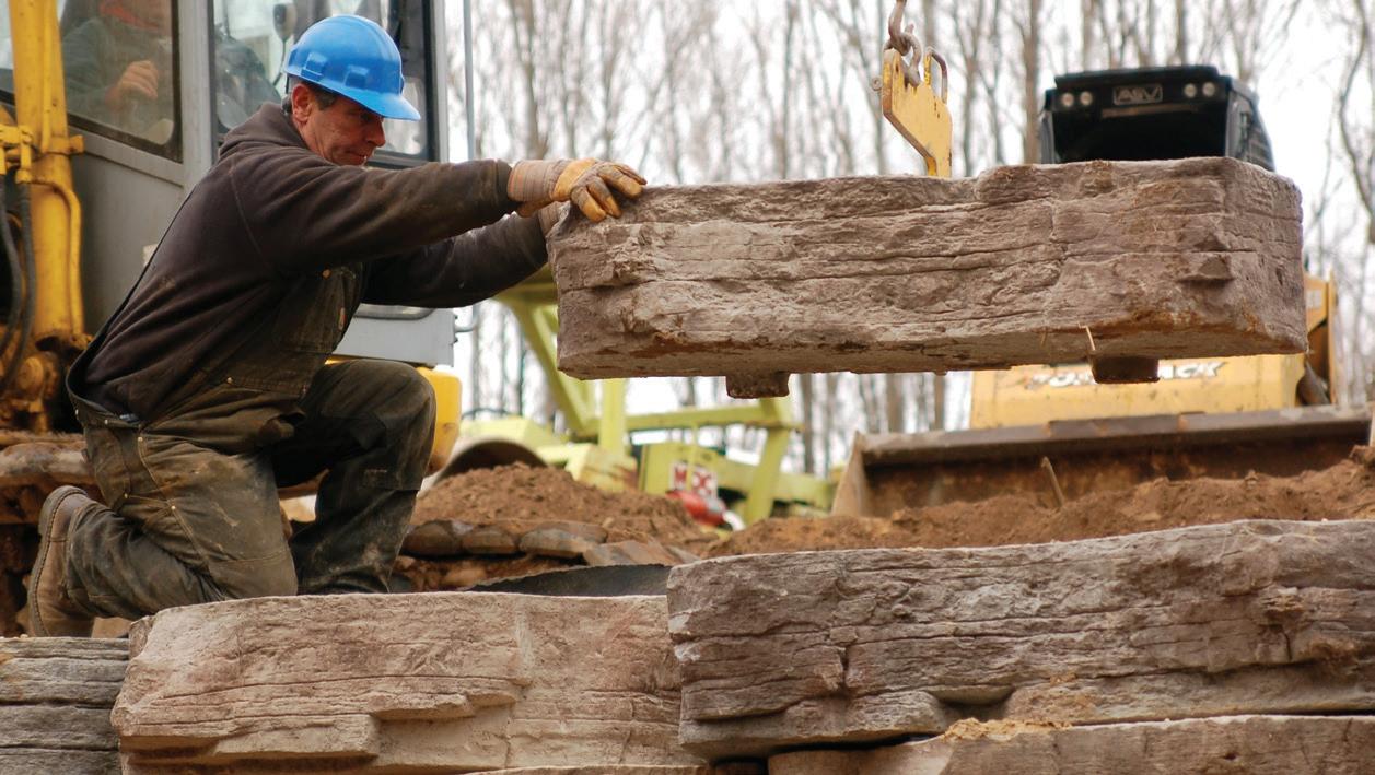
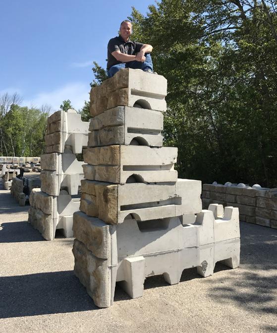
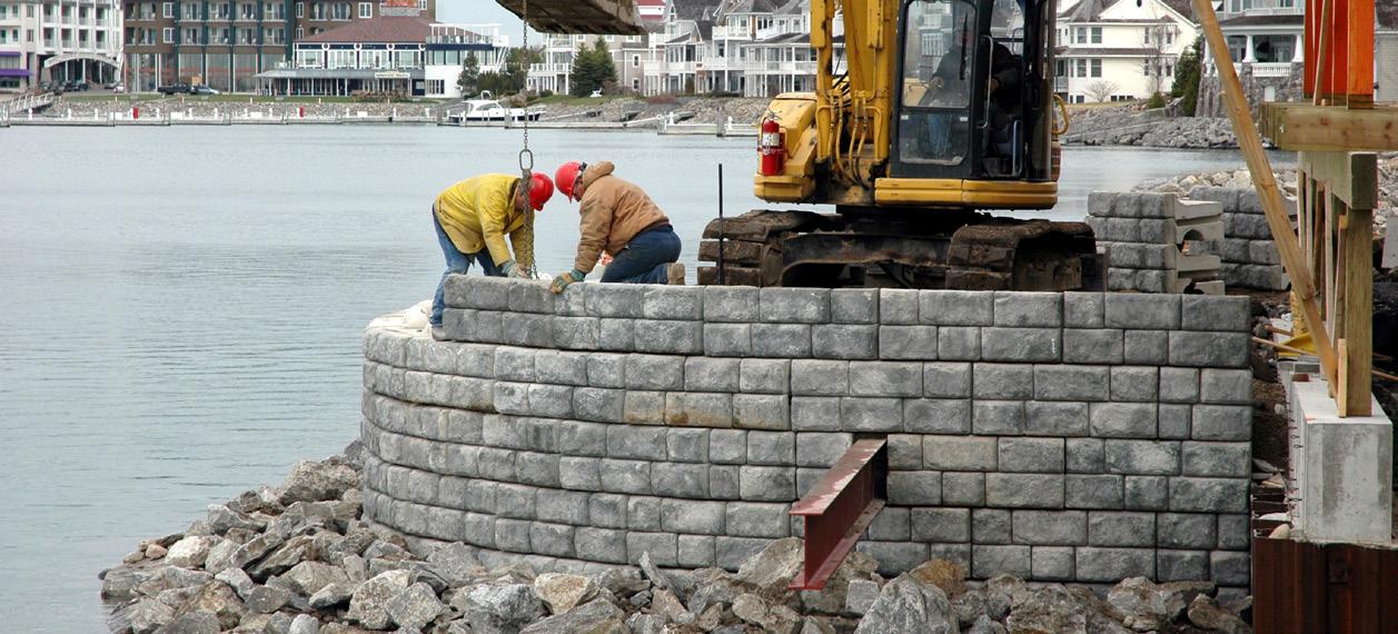
PMB units vary in size, but generally range between a few hundred pounds to several thousand pounds each. PMB units are almost exclusively set by large construction equipment. Figure 1.4 shows an example of PMB wall installation.
3INTRODUCTION PRECAST MODULAR BLOCK DESIGN MANUAL VOLUME 1: GRAVITY WALLS
Fig. 1.4. Example PMB wall installation.
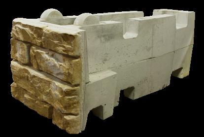
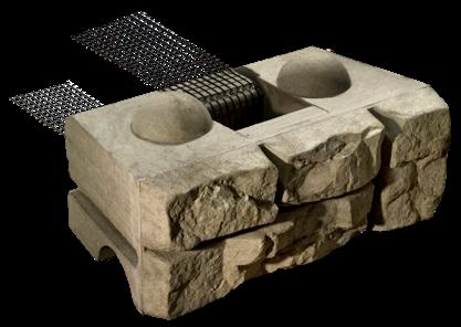
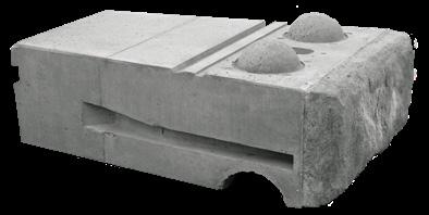
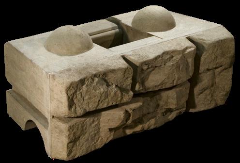
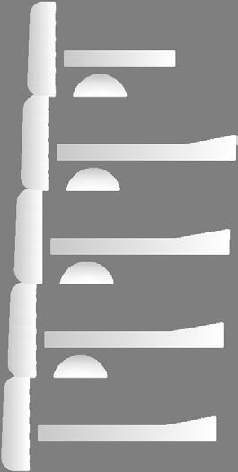
PMB units can be solid, slotted, or hollow. They are closed cell units. Example PMB units are shown in figure 1.5.
Fig. 1.5. Example PMB units.
PMB units often have some form of interlock mechanism such as a knob and groove or lugs, used to establish the horizontal setback between successive rows of units. The interlock may also provide block-to-block shear transfer between successive rows of PMB units. An example interlock is shown in figure 1.6.
4 INTRODUCTION
PRECAST
MODULAR BLOCK DESIGN MANUAL VOLUME 1: GRAVITY WALLS
Fig. 1.6. Example PMB unit interlock mechanism.
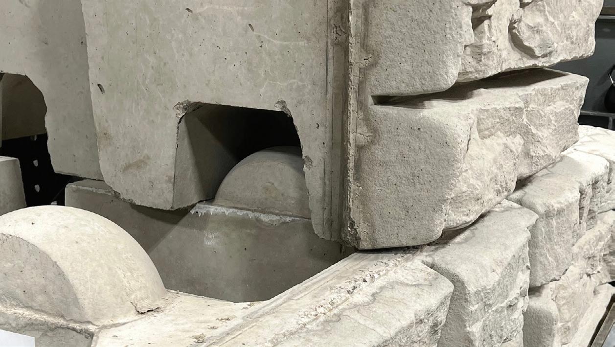
PMB units typically have tapered sides to accommodate curved wall installations like that shown in figure 1.7. There are also special units which allow for construction of corners as shown in figure 1.8.
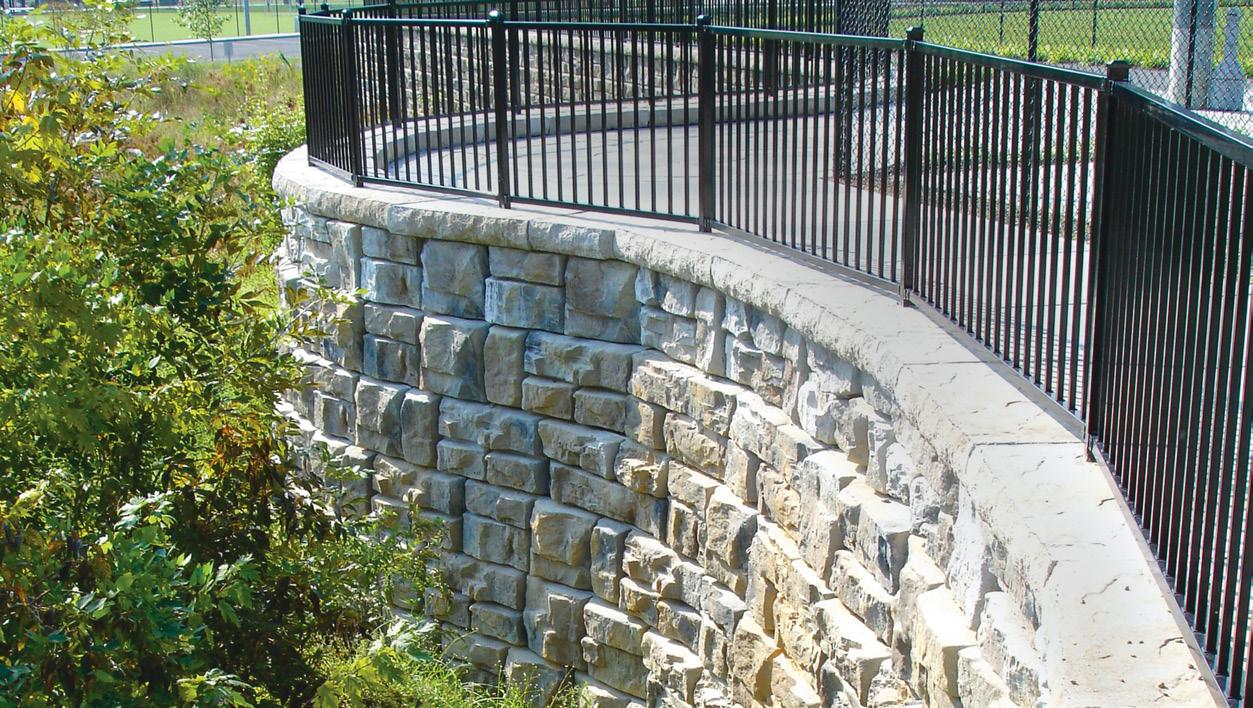
Fig. 1.7. Curved PMB wall.
5INTRODUCTION
PRECAST MODULAR BLOCK DESIGN MANUAL VOLUME 1: GRAVITY WALLS
1.3. BENEFITS OF PMB WALLS
PMB walls have seen rapid adoption and are quickly becoming the preferred solution for many retaining wall applications. This is largely due to the fact that there are many benefits inherent in the use of PMB units.

PMB units are produced in factory-controlled conditions. Quality management plans followed by the manufacturer assure high-quality units that meet, and often exceed, minimum product specifications for strength, quality, dimensional tolerance, and appearance. PMB units also provide excellent performance in freeze-thaw conditions.
The units are allowed to cure in controlled conditions and when they are ultimately shipped to the job site, PMB units are ready for immediate use. There is no delay for forming, casting, and waiting for concrete to cure before backfilling operations. In fact, these units are often used in emergency repairs specifically for this reason.
Wet-cast concrete is a perfect material to form into complex, highly textured surfaces and PMB units generally have architectural face textures crafted by artisan mold makers. The texture is often up to 6 inches (150mm) in depth, and some units are textured on multiple faces (front, back, top, and/or both ends). Figure 1.9 shows an example texture.
Due to their size, PMB units can be stacked to create stable retaining walls of significant heights without requiring additional measures like soil reinforcement or anchors. This often leads to PMB units being pre ferred in cut wall applications, since they won’t re quire additional excavation for soil reinforcement.
6 INTRODUCTION
PRECAST MODULAR BLOCK DESIGN MANUAL VOLUME 1: GRAVITY WALLS
Fig. 1.8. PMB wall featuring corner construction.
Fig. 1.9. Example PMB face texture.
Select PMB units offer multiple setback options that allow for walls to be constructed with varying batter angles. PMB units with different block-to-block setbacks can be combined in the same cross-section to create walls with different batter angles like the wall shown in figure 1.10
PMB units may be produced in multiple sizes, allowing walls with bigger units on the bottom and smaller units further up the wall. This construction provides stability where needed while allowing engineers to design truly optimized retaining structures. An example of different width units is shown in figure 1.11.
PMB units provide for fast, efficient installation. They are set with large construction equipment and enjoy the resulting productivity gains. PMB units are also typically installed with smaller crews, maximizing the use of on-site labor. With a properly prepared construction site and base course, installation can proceed rapidly in almost a stack-and-go fashion. An example installation using a large excavator is shown in figure 1.12.
7INTRODUCTION
PRECAST
MODULAR BLOCK DESIGN MANUAL VOLUME 1: GRAVITY WALLS
Fig. 1.10. PMB wall with different block-to-block setbacks.
Fig. 1.11. Different width PMB blocks within a shared cross-section.
Fig. 1.12 PMB wall installation with equipment.
The larger size and heavier weight of PMB units aid in achieving desired compaction of backfill materials during installation. They do not easily shift during the operation of plate compactors and other construction equipment immediately behind the wall, unlike smaller, lighter retaining wall units.
1.4. TYPICAL GRAVITY RETAINING WALL WITH PMB UNITS
A cross-section highlighting the main components of a gravity PMB wall is shown in figure 1.13.
Fig. 1.13. Main components of a gravity PMB wall.
8 INTRODUCTION PRECAST MODULAR BLOCK DESIGN MANUAL VOLUME 1: GRAVITY WALLS
Although many of the specific items shown will be discussed in more detail throughout this manual, a brief overview is helpful.
PMB units are large concrete blocks whose size and weight resist sliding and overturning forces from the retained soil and can be used to construct fabulous retaining walls. They often boast features that allow them to interlock with the PMB units in the rows immediately above and below.
Existing site soils are excavated to desired elevations and compacted to provide a subbase for the wall. If the existing soils are not suitable to support the wall, the design will include some type of foundation improvement in the subbase.
A leveling pad of compacted stone, gravel, or lean concrete is constructed on which to place the PMB units and build the wall.
PMB units are placed in horizontal rows and backfilled as the wall is constructed from the bot tom up. Any void space in or between units, is filled with clean, open-graded stone backfill ma terial. This backfill material may be referred to as infilled stone, drainage aggregate, or core fill.
A drain is installed at the bottom of the wall to collect any water that flows through the retained soil and infilled stone and move it away from the wall.
Some type of separator is used to keep any small grained particles in the retained soil from migrating into the infilled stone. Non-woven geotextile fabric is the most common, but a gran ular filter with carefully graded particle sizes is also used on some projects.
9INTRODUCTION PRECAST MODULAR BLOCK DESIGN MANUAL VOLUME 1: GRAVITY WALLS
1.5 REFERENCES
AASHTO (2012) LRFD Bridge Design Specifications, American Association of State Highway and Transportation Officials, Washington, D.C.
AASHTO (2020) LRFD Bridge Design Specifications, Ninth Edition, American Association of State Highway and Transportation Officials, Washington, D.C.
AASHTO M43 (2005), Standard Specification for Sizes of Aggregate for Road and Bridge Construction, American Association of State Highway and Transportation Officials, Washing ton, D.C.
ASCE 7-16 (2017) Provisions and Commentary, Minimum Design Loads and Associated Cri teria for Buildings and Other Structures (ASCE/SEI 7-16), American Society of Civil Engineers, Reston, Virginia
ASTM C33 C33M-13, Standard Specification for Concrete Aggregates, ASTM International, West Conshohocken, PA, 2021, www.astm.org
ASTM C94 / C94M-21, Standard Specification for Ready-Mixed Concrete, ASTM International, West Conshohocken, PA, 2021, www.astm.org
ASTM C1776 / C1776M-17, Standard Specification for Wet-Cast Precast Modular Retaining Wall Units, ASTM International, West Conshohocken, PA, 2017, www.astm.org
ASTM D698-12, Standard Test Methods for Laboratory Compaction Characteristics of Soil Using Standard Effort (12 400 ft-lbf/ft3 (600 kN-m/m3)), ASTM International, West Consho hocken, PA, 2014, www.astm.org
ASTM D1557-07, Standard Test Methods for Laboratory Compaction Characteristics of Soil Using Modified Effort (56,000 ft-lbf/ft3 (2,700 kN-m/m3)), ASTM International, West Consho hocken, PA, 2010, www.astm.org
ASTM D2487-17, Standard Practice for Classification of Soils for Engineering Purposes (Uni fied Soil Classification System), ASTM International, West Conshohocken, PA, 2017, www. astm.org
ASTM D6913/D6913M-17, Standard Test Methods for Particle-Size Distribution (Gradation) of Soils Using Sieve Analysis, ASTM International, West Conshohocken, PA, 2021, www.astm.org
ASTM D6916-18, Standard Test Method for Determining the Shear Strength Between Seg mental Concrete Units (Modular Concrete Blocks), ASTM International, West Conshohocken, PA, 2017, www.astm.org
ASTM D7928-21, Standard Test Method for Particle-Size Distribution (Gradation) of FineGrained Soils Using the Sedimentation (Hydrometer) Analysis, ASTM International, West Conshohocken, PA, 2021, www.astm.org
Bowles, Joseph E., (1996) Foundation Analysis and Design, Fifth Edition, McGraw-Hill, New York, NY
10 INTRODUCTION PRECAST MODULAR BLOCK DESIGN MANUAL VOLUME 1: GRAVITY WALLS
Coduto, Donald P. (2001) Foundation Design Principles and Practices, Second Edition, Pren tice Hall, Upper Saddle River, New Jersey
DIN 4085:2017-08, (2017) German Standards, ICS 93.020, Subsoil - Calculation of Earth Pressure, Beuth Publishing DIN, Berlin, Germany
FHWA-NHI-07-071 (2008) Earth Retaining Structures Reference Manual, U.S. Department of Transportation, Federal Highway Administration, Washington, D.C.
FHWA-NHI-10-024 (2009) Design and Construction of Mechanically Stabilized Earth Walls and Reinforced Soil Slopes Vol. I, U.S. Department of Transportation, Federal Highway Ad ministration, Washington, D.C.
FHWA-NHI-10-025 (2009) Design and Construction of Mechanically Stabilized Earth Walls and Reinforced Soil Slopes Vol. II, U.S. Department of Transportation, Federal Highway Ad ministration, Washington, D.C.
ICC IBC-2021 (2020), 2021 International Building Code, International Code Council, 2020
Janbu, N., (1957), Earth pressure and bearing capacity calculations by generalized proce dure of slices, 4th International Conference on Soil Mechanics and Foundation Engineering, London, England
Leshchinsky, Ben (2015) Bearing Capacity of Footings Placed Adjacent to c’-φ’ Slopes, Jour nal of Geotechnical and Geoenvironmental Engineering, Col. 141, No. 6, American Society of Civil Engineers, Reston, VA
Leshchinsky, Ben and Xie, Yonggui, (2016) Bearing Capacity for Spread Footings Placed Near c’-φ’ Slopes, Journal of Geotechnical and Geoenvironmental Engineering, American Society of Civil Engineers, Reston, VA
Meyerhof, G. G., (1957) The Ultimate Bearing Capacity of Foundations on Slopes, The Pro ceedings of the Fourth International Conference on Soil Mechanics and Foundation Engineer ing, London, August 1957
National Cooperative Highway Research Program (2010), NCHRP REPORT 663, Design of Roadside Barrier Systems Placed on MSE Retaining Walls, Transportation Research Board, Washington, D.C.
NAVFAC (1982), Soil mechanics: Design Manual 7.1, United States Department of the Navy, Naval Facilities Engineering Command, Washington, D.C.
NAVFAC (1982), Foundations and Earth Structures, Design Manual 7.2, United States Depart ment of the Navy, Naval Facilities Engineering Command, Washington, D.C.
Rahardjo H., and Fredlund D., (1984), General limit equilibrium method for lateral earth force, Canadian Geotechnical Journal, Volume 21, Number 1, February 1984
Terzaghi, Karl and Peck, Ralph B. (1967), Soil Mechanics in Engineering Practice, Second Edi tion, John Wiley & Sons, New York, NY
11INTRODUCTION PRECAST MODULAR BLOCK DESIGN MANUAL VOLUME 1: GRAVITY WALLS
United States Department of Agriculture, Soil Conservation Service (1990), Engineering Field Manual, Chapter 4, Elementary Soil Engineering, Soil Conservation Service, Washington, DC. Winterkorn, Hans F. and Fang, Hsai-Yang (1975) Foundation Engineering Handbook, Van Nos trand Reinhold Company, New York, NY
12 INTRODUCTION
PRECAST MODULAR BLOCK DESIGN MANUAL VOLUME
1:
GRAVITY WALLS
CHAPTER 2.0 DESIGN INPUTS
2.1. WHERE TO START
PMB walls have gained widespread use over the past two decades. As a result, there is a vast and growing network of people possessing both knowledge of and experience with PMB walls. The associated engineering principles are easily understood and applied to PMB walls by civil engineers, geotechnical engineers, structural engineers, and others with training to specialize in retaining wall design. Precast concrete producers across the globe have expertise in manu facturing, inventorying, and shipping the different types of PMB units required for a successful project. General contractors and specialty wall construction contractors have experience in stalling PMB retaining walls. The knowledge and skills are there and they are simple to access.
This manual focuses on the engineering principles used for PMB walls. It serves as a reference for the wall design community.
Companies like Aster Brands that create and license PMB units (Redi-Rock and Rosetta Hard scapes) are a great source of information for typical applications, use of the products, design parameters, and locating manufacturers.
Local precast concrete producers provide expertise and knowledge including local projects, available products, pricing, experienced installers, etc.
Local contractors and those who have constructed PMB walls can also be valuable sources of information regarding constructability, locally available materials, etc.
Pick up the phone, send an email, or ask someone you know. Plenty of people are available to help.
2.1.1. Typical Steps for Design and Construction of a Wall
A simplified flowchart of the recommended steps for a successful PMB retaining wall project is provided in figure 2.1.
13DESIGN INPUTS PRECAST MODULAR BLOCK DESIGN MANUAL VOLUME 1: GRAVITY WALLS
Fig. 2.1. Design and construction process for a PMB retaining wall.
These steps may seem overly simple, but they capture the major elements required for a good wall project. A few notes to consider:
• As you move through the process, cost estimates get better, the wall solution becomes optimized, and confidence in the successful completion of your project increases.
• Some of the steps may be combined depending on the project and the familiarity of the parties involved with PMB wall design and construction.
• Proper soil investigation is critical. It is impossible to have a reliable, optimized wall without determining the soil conditions.
• The key to successful implementation is to get the right level of information at the right time in the process. Conducting a series of soil borings, running detailed laboratory tests, or preparing final, sealed plans and specifications before determining that the project is feasible doesn’t make sense. Conversely, trying to prepare detailed design documents with incomplete information is also counterproductive to the success of your project.
• Often people will consult with companies that license PMB units or with the local manufacturer to get assistance choosing a particular PMB solution or evaluating feasibility of the project in the initial evaluation. Typically, tools like preliminary height guides in the form of charts or sample cross-sections and example details are available to help at this stage.
• Some companies that license PMB units provide software to aid in the evaluation of PMB walls. Aster Brands offers Redi-Rock Wall+, software that calculates wall
14 DESIGN INPUTS PRECAST MODULAR BLOCK DESIGN MANUAL VOLUME 1: GRAVITY WALLS
stability. Redi-Rock Wall+ is written by Fine Software, the company behind the GEO5 suite of products for the civil engineering industry.
2.1.2. Project Team
Many people are often involved in the planning, design, and construction of a retaining wall. Some of the most common roles in a project team and their typical responsibilities are de scribed in Table 2.1.
TABLE 2.1
TYPICAL PROJECT TEAM
• Own the project site (with all its existing conditions) and recognize the need to improve usability of the site through construction of a retaining wall.
• Communicate clear direction on project requirements.
Owner
• Provide payment for professional and construction services.
• Acceptance of the project and ultimate assumption of risk.
• Perform ongoing inspections and maintenance.
General Civil Engineer
• Manage overall site, grading, and utility design. (Note: It is very important that the General Civil Engineer understands the impact of these designs on the feasibility, constructability, and cost of the retaining wall.)
• Perform detailed investigation of site soils.
• Review boring logs, soil samples and test data.
Geotechnical Engineer
General Contractor
Wall Installation Contractor
PMB Manufacturer
• Recommend design parameters for geotechnical analysis.
• Determine overall (global) stability of the retaining walls and slopes on the site.
• Estimate settlement of proposed walls and other structures.
• Verify site conditions match those specified in the wall design.
• Execute all site and utility construction.
• Construct retaining wall(s), per detailed plans and specifications prepared by the Wall Design Engineer.
• Manufacture PMB units in accordance with published strength, quality, and dimensional tolerance specifications.
• Deliver PMB units to the construction site in the order needed and according to the requirements of the construction schedule.
• Verify minimum required design parameters, soil information, and wall requirements are provided.
Wall Design Engineer
• Perform wall design per established engineering principles to provide minimum levels of design reliability (FS or CDR).
• Prepare detailed construction drawings (plans) and specifications that can be used to construct the retaining wall(s).
• Verify overall (global) stability with detailed wall design.
Construction Inspector
• Verify that construction is carried out in accordance with the construction drawings and specifications.
2.1.3. Information Required to Design a Wall
The more information available in planning and design of a retaining wall, the more likely the wall will be properly designed to meet project requirements. Design and construction of a
15DESIGN INPUTS PRECAST MODULAR BLOCK DESIGN MANUAL VOLUME 1: GRAVITY WALLS
wall with limited, incomplete, or missing information requires someone to guess at conditions. Even if missing information does not lead to a wall failure, it often results in a wall that is either underdesigned for the actual conditions and does not provide the desired level of reliability or is overdesigned and costs more than it should.
Here is a list of information often required to design a wall.
• Wall geometry and site grading
Exposed wall height
Top of wall / bottom of wall profile or elevation callouts
Crest slope on the top of the wall
Toe slope on the bottom of the wall
Site grades
Drainage patterns (before, during, and after construction)
• Detailed geotechnical information
All existing and proposed soils
Internal Friction Angle (φ)
Unit Weight (γ) (dry, moist, and saturated)
Cohesion (c)
Soil USCS Classification
Soil Gradation / Results of sieve analysis
Liquid Limit (Fine grained soils)
Plastic Limit (Fine grained soils)
Soil boring logs and boring locations
Composition and elevation of soil layers
Groundwater elevations and rates of flow
Rock quality and location (consolidated rock areas)
Presence of slickensides or perched water tables
Presence of special soils like expansive clays or quick clays
Wall design envelope
Distance to property lines
Distance to buildings
Other obstructions in the area that would impact the wall
Limits in allowable excavation
Site Utilities
Location and elevations of all site utilities (water, sanitary sewer, storm sewer, electric, fiber optic, cable, gas, irrigation, and others)
Light pole base sizes, locations, and loading
Pipe penetrations through proposed wall including location, diameter, material, and invert elevations
Wall loading
Supported loads (parking lots, roadways, or other loads and their distance from proposed wall)
Foundation type and location for buildings and structures near proposed wall
Seismic loads
Peak ground acceleration
Seismic coefficients, Kh and Kv
Allowable displacement
Liquefaction potential of site soils
Water
Groundwater
16 DESIGN INPUTS PRECAST MODULAR BLOCK DESIGN MANUAL VOLUME 1: GRAVITY WALLS
◦
◦
◦
◦
◦
◦
◦
▪
▪
▪
▪
▪
▪
▪
◦
◦
◦
◦
◦
◦
•
◦
◦
◦
◦
•
◦
◦
◦
•
◦
◦
◦
▪
▪
▪
▪
•
◦
Surface water
Rapid drawdown requirements
Maximum potential scour elevations
Leveling pad requirements
Crushed stone
Lean concrete
Reinforced concrete footing
Unusual / special conditions or requirements
PMB Unit properties
Size
Infilled unit weight
Block-to-block interface shear capacity
Design requirements
Minimum factors of safety or load and resistance factors
Sliding
Overturning
Eccentricity
Bearing capacity
Global stability
Load combinations
Wall design submittal requirements
• Top of wall requirements
Cap, freestanding / parapet wall, fence, handrail, guardrail, or drainage swale
Of course, no single list can cover every project or situation. Some of the above items may not apply to your project or you may need additional information not includ ed in this list. This raises a very important point. Your wall should be designed by a li censed, professional engineer with experience in retaining wall design. If conditions call for more information, the engineer should be able to address the specific situation.
2.2. PMB UNIT PROPERTIES
PMB units come in varying size and shape. PMB units from the same manufactur er are often designed to work together. For example, Redi-Rock solid units, PC units, XL units, and Freestanding units can all be combined together in the same section to optimize the wall design. Properties for each unit are provided by the manufacturer.
2.2.1. Size
PMB units are defined by length, width, and height. ASTM C1776 notation defines length being measured parallel to the wall face, width being measured perpendicular to the wall face, and height being measured vertically as shown in figure 2.2.
2.2.2. Infilled Unit Weight
Fig. 2.2. PMB dimensions guide.
Granular infill material is placed in any hollow cores in a PMB unit and in all spaces between adjacent PMB units. A well-graded gravel, such as ASTM No. 57 stone, is commonly used. The infill material should be placed and compacted with a tamping rod or post until the material has reached maximum density and won’t compact any more. It fills void spaces in and around
17DESIGN INPUTS PRECAST MODULAR BLOCK DESIGN MANUAL VOLUME 1: GRAVITY WALLS ◦
◦
◦
•
◦
◦
◦
•
•
◦
◦
◦
•
◦
▪
▪
▪
▪
▪
▪
◦
◦
PMB units, limiting migration of retained soil into these spaces, and it provides additional weight to help resist destabilizing forces that would cause sliding or overturning of the wall.
Design of a PMB wall takes into account both the weight of the concrete PMB unit and the infill material. An example calculation is shown in figure 2.3.
Fig. 2.3. Example infill weight and center of gravity calculations.
2.2.3. Block-to-Block Interface Shear
Walls constructed with PMB units are neither completely solid nor rigid bodies. They are built from individual units, placed in rows and stacked without the use of mortar, adhesive, or other materials to cement the units together. However, most PMB units have knobs, lugs, or similar features that help establish the setback between successive rows of PMB units and provide transfer of forces between units in the wall.
The ability to transfer forces from a PMB unit to the units above and below it in the wall is referred to as “block-to-block inter face shear capacity.” The value of interface shear is determined by full scale lab testing of PMB units. A large scale test frame at the Aster Brands testing facility in Charlevoix, Michigan is shown in figure 2.4.
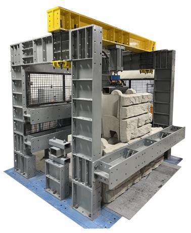
ASTM D6916 Standard Test Method for Determining the Shear Strength Between Segmental Concrete Units (Modular Concrete Blocks) defines the test method most commonly used to deter mine block-to-block interface shear capacity. In this test method, one unit (or block) is set on top of two blocks in a staggered, running bond pattern. Base units are firmly fixed and a normal load is applied vertically to simulate varied height walls. The up per unit is then pushed horizontally to failure to determine the peak interface shear capacity between the units. Tests are run until there is excessive deflec tion, visible cracking seen in the test units, or significant reduction in applied load. The results are plotted on a graph, with the maximum horizontal load plotted on the vertical axis and the associated vertical load for that test plotted on the horizontal axis. A two or three segment
Fig. 2.4. Example large scale test frame for block-to-block interface shear testing.
18 DESIGN INPUTS PRECAST MODULAR BLOCK DESIGN MANUAL VOLUME 1: GRAVITY WALLS
curve is often established to define the block-to-block interface shear capacity of the partic ular PMB units. An example is shown in figure 2.5. Some test reports, particularly older test reports, include additional service state shear values at a prescribed amount of displacement such as 2% of the unit height. PMB walls have excellent performance history and do not tend to be subject to movement of individual PMB units within the wall. As such, many designers evaluate sliding between rows of PMB units ina wall at peak strength but do not perform an additional serviceability check.
2.3. SOILS
Soils that make up the area around a retaining wall and surrounding slopes are the largest single factor that impact the wall’s design, construction, and performance. The formulas or computer programs used to calculate earth pressures and determine wall stability require a few basic inputs to define the strength of the soils such as unit weight, internal angle of friction, and cohesion. These properties are influenced by other factors such as soil density, percentage of fine grained particles in the soil, liquid limit, and plasticity index. The real art and science of wall design does not come from the calculations, it is generated from knowing which specific values to use when running the calculations. This manual briefly reviews basic soil properties required to analyze a retaining wall, but it should not be considered a detailed soil mechanics textbook. A thorough grasp of soil behaviors is essential to effectively understand and use this manual.
2.3.1. Soil Classification
Multiple soil classification systems have been developed over the years. For this manual’s purposes, we will reference the USCS Soil Classification as detailed in ASTM D2487, Standard Practice for Classification of Soils for Engineering Purposes (Unified Soil Classification System) . The USCS lists basic soil types as gravels, sands, silts, clays, or organic/peat. The reader is referred to the ASTM standard for details and further classifications.
2.3.2. Shear Strength
Shear strength of soil is the resistance to mass deformation from a combination of particle rolling, sliding, and crushing, and is reduced by any pore pressure that exists or develops
19DESIGN INPUTS PRECAST MODULAR BLOCK DESIGN MANUAL VOLUME 1: GRAVITY WALLS
Fig. 2.5. Example block-to-block interface shear capacity test data.
during particle movement (Bowles, 1996). Shear strength is measured in terms of two param eters – internal angle of friction and cohesion – both of which can be shown by plotting the shear strength of a soil at different levels of normal stress. The resulting visual representation is often called a Mohr-Coulomb diagram (an example is shown in figure 2.6) and is further described below.
Fig. 2.6. Example Mohr-Coulomb diagram of a soil.
Internal angle of friction (φ) is the resistance of slip between particles in the soil. It is a measure of the increase in the shear strength of the soil with increased normal stress and is calculated as the slope of the line in the shear stress vs. normal stress curve. The internal angle of friction for coarse grained soils is influenced by grain size, angularity of the soil particles, and density. The internal angle of friction for fine-grained materials is influenced by stress conditions, move ment, plasticity/liquid limit, moisture content/void ratio, stress history, and clay mineralogy. Care must be taken to use an appropriate value of internal angle of friction for fine-grained soils.
Cohesion (c) is the measure of attraction between soil particles at no normal stress and is calculated as the y-intercept of the shear stress vs. normal stress curve. Cohesion comes from negative pore pressures locked into soils from prior loading, molecular-scale electrical at traction, and sometimes cementation. Cohesion is not a constant value. It changes with pore pressure and/or movement of the soil. Additionally, most normally consolidated soils do not have true cohesion and long-term loading results in only frictional strength. As a result, most wall designers ignore cohesion of the retained soil and do not consider its effect on reducing the earth pressure on a wall.
Geotechnical engineers make a distinction between shear strength parameters measured in either drained or undrained conditions. The terms short-term and long-term strength are also used when referring to undrained or drained conditions. Shear stress in the soil is measured in a lab either with a direct shear box or in one of the tests that can be performed in a triaxial compression testing machine. If the loading is applied slowly enough to allow water in the soil to move between soil particles, excess pressure from the water does not develop and the shear strength is considered to be drained. If the loading is applied quickly, water in the soil does not have time to move between soil particles and pore pressure develops and impacts the shear stress and the shear strength is considered to be undrained.
20 DESIGN INPUTS PRECAST MODULAR BLOCK DESIGN MANUAL VOLUME 1: GRAVITY WALLS
An example of how shear stress, strain, and normal stress behave in drained conditions is shown in figure 2.7.
Fig. 2.7. Example plot of drained behavior of soils. As can be seen in the plot of shear stress vs. strain, soil strength values can be peak, fully-soft ened, or residual depending on how much movement is allowed.
An example of shear stress vs. normal stress for undrained conditions is shown in figure 2.8.
Fig. 2.8. Example plot of undrained behavior of soils.
Shear strength, defined by both the internal angle of friction and cohesion, is not constant but changes with conditions. Shear strength can be defined as drained, undrained, peak, fully softened, residual, intact, remolded, static, cyclic, compression, or extension. It sounds complicated – and it is – which is why a good understanding of soil mechanics is necessary to know the appropriate strength properties to use in design calculations. If you do not possess a strong background in soil mechanics, engage the expertise of a geotechnical engineer who does. Proper selection of strength parameters for the soils might be the single most import ant factor to the success of your project. As highlighted previously, calculations based upon incorrect soil parameters can result in a wall that is underdesigned for the actual conditions
21DESIGN INPUTS PRECAST MODULAR BLOCK DESIGN MANUAL VOLUME 1: GRAVITY WALLS
and does not provide the desired level of reliability or a wall that is overdesigned and costs more than it should.
2.3.3. Unit Weight, Density, and Compaction
Soils are made up of solids, water, and air. The proportions of each impacts the engineering behavior of the soil. Unit weight, density, and compaction are concepts that help describe soils.
Unit weight of the soil is the total weight of the soil particles and water in a given volume and is typically expressed in units of pounds per cubic foot or kilograms per cubic meter. The unit weight of the soil depends upon the specific gravity of the particles comprising the soil, the gradation and shape of the particles, relative density or compaction of the soil, and its water content.
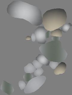
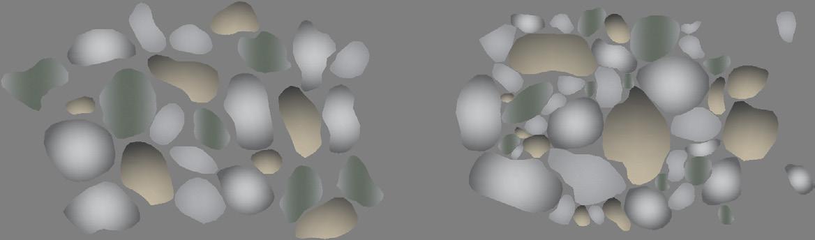
Relative density (often just called density) of the soil is the ratio of the soil’s in-place density to its maximum density. It is a measure of how tightly the soil particles are packed together. There is an optimal arrangement of particles that provides the maximum density. Figure 2.9 shows conceptual examples of soils with different densities.
Fig. 2.9. Conceptual comparison of loose and dense soils.
Dense soils tend to have higher shear strength than loose soils. As the relative density increases and the particles are packed more tightly together, it is more difficult for the particles to get around one another when sheared, requiring the soil to dilate. Dense soils also tend to be less compressible than loose soils, so will not tend to settle as much under load.
Soils, especially fill soils, can be compacted to make them denser – increasing their strength and reducing potential for settlement. The selection compaction methods will be based on the soil type, with vibratory compactors (plates or rollers) used for coarse-grained soils (sands and gravels) and kneading-type compactors (such as sheepsfoot rollers) used for soils with larger percentages of fine-grained particles.
Water plays an important role in compaction of soils, with a soil being easier to compact to a higher density at a specific “optimum” water content. The maximum dry density of a soil varies with the water content at which it is compacted. The optimal water content corresponds to the maximum density the soil can achieve under the specified effort. An example moisture-density curve is shown in figure 2.10.
22 DESIGN INPUTS PRECAST MODULAR BLOCK DESIGN MANUAL VOLUME 1: GRAVITY WALLS
Fig. 2.10. Example moisture-density curves.
Construction specifications often require that soils be compacted to some percentage of the maximum dry density. In most cases, compaction is determined using a specific effort –commonly defined in either ASTM D698-12, Standard Test Methods for Laboratory Compaction Characteristics of Soil Using Standard Effort (12 400 ft-lbf/ft3 (600 kN-m/m3)) or ASTM D1557-07
Standard Test Methods for Laboratory Compaction Characteristics of Soil Using Modified Effort (56,000 ft-lbf/ft3 (2,700 kN-m/m3)) - at the soil's optimum water content. In other instances, such as when specifying compaction of crushed stone, engineers will call for a minimum amount of compactive effort with a specific piece of equipment. An example would be requiring a minimum of three passes with a 24-inch (610 mm) wide, walk-behind, vibrating plate compactor capable of delivering at least 2000 lb (8.9 kN) of centrifugal force.
A given piece of compaction equipment is only effective to a certain depth, with its energy attenuating rapidly as the lifts get thicker. Larger, heavier equipment will generally be able to compact to greater depths, whereas lighter, walk-behind equipment will be limited to just a few inches. Construction specifications often restrict the thickness of lifts of fill that can be compacted at one time. They will also limit the type of equipment that can be used close to the retaining wall.
2.3.4. Soils Types and Walls
In a perfect world, all the soils that impact a wall would be well-drained, densely compacted, coarse-grained soils with high levels of internal shear strength such as dense sands and gravels. Engineers prefer these soils because they do not tend to retain water, building up extra pressure on the wall. Their properties do not exhibit different short and long term behavior, they are not generally subject to creep (slow movement over time), and they are relatively easy to compact.
Fine-grained soils, soils that have a significant portion of particles that can pass through a number 200 sieve, such as clays and silts are not well suited for use as backfill material for retaining walls. Fine grained soils can be slow draining and they often possess low angles of internal friction. They may develop tension cracks near the ground surface, allowing water pressure to build up against the wall. Water retained in fine-grained soils can freeze, developing ice pressures on the back of the wall.
23DESIGN INPUTS PRECAST MODULAR BLOCK DESIGN MANUAL VOLUME 1: GRAVITY WALLS
On-site soil conditions may vary considerably. When the retained or foundation soils are not optimal, wall designers need to either work with the existing material or change the conditions to allow for construction of a wall.
Achievable wall heights can be extended, especially for projects where the retained soils are soft and weak, by excavating enough existing soil and replacing it with compacted, select fill material. It is very common for wall designers to excavate a wedge of material to a 45° angle (1 horizontal on 1 vertical slope) or flatter and replace that material with crushed stone or gravel. These materials possess higher internal strength and will put less pressure on the wall. The authors have been able to find a version of this solution documented at least as far back as the United States Department of Agriculture, Soil Conservation Service (1990). An example is shown in figure 2.11.
Fig. 2.11. Crushed stone backfill wedge.
Similarly, engineers can design for walls on soft foundation soils by incorporating some type of foundation improvement. In some cases, this may be as simple as excavating existing material as needed and replacing it with highly compacted gravel or stone, often wrapped in a geotextile material. An example is shown in figure 2.12.

24 DESIGN INPUTS PRECAST MODULAR BLOCK DESIGN MANUAL VOLUME 1: GRAVITY WALLS
2.4.
Fig. 2.12. Example foundation improvement measures.
Should these solutions prove insufficient to allow for design and construction of the wall, a geotechnical engineer may offer more advanced solutions such as pile supported foundations or anchored walls.
Two soil conditions that require special attention are expansive soils and organic soils: Expansive soils are clayey soils that contain minerals such as montmorillonite. These soils exhibit large volume changes in response to water content, both swelling and shrinking. Expansive soils can put significant pressure on a wall and shrinkage cracks that develop in expansive soils can easily fill with water.
Organic soils and peats have low undrained shear strength and are highly compressible. They offer poor bearing capacity and high long-term settlement.
Expansive soils and organic soils should be removed from wall sites.
Occasionally, wall designers may encounter rare soil types such as quick clays, permafrost, or corrosive soils which are beyond the scope of this manual. Consult a geotechnical engineer should your site include any of these soil types.
WALL GEOMETRY
Nomenclature for PMB gravity walls is similar to that used for most wall types. Some major features are shown in figure 2.13.

25DESIGN INPUTS PRECAST MODULAR BLOCK DESIGN MANUAL VOLUME 1: GRAVITY WALLS
Fig. 2.13. PMB gravity wall geometry.
The “top of the wall” is defined as the top of the highest PMB unit in the wall.
Although civil engineers primarily concerned with site grades will consider the ground elevation at the base of the wall the “bottom of wall”, wall designers consider the bottom of the wall to be either the lowest edge of the bottom PMB unit or the bottom of the leveling pad. This distinction typically depends on the particular failure mode being investigated.
The “toe of the wall” is considered the bottom front corner of the lowest PMB unit being con sidered in the particular calculation. For external stability calculations (described later in this manual), the toe of the wall is the bottom front corner of the bottom PMB unit.
“Embedment” or “bury depth” is the height of soil in front of the wall near the toe.
Wall height is measured from the top of the wall to the bottom of the wall and includes both the exposed wall height and the embedment.

A slope at the top of the wall is called the “crest slope” or “top slope”.
A slope at the bottom of the wall is referred to as a “toe slope” or the “bottom slope”.
2.4.1. Batter
“Batter” is the term used to describe the average slope of the face or back of the wall. The concept of wall batter is common in retaining wall design, especially when the wall is a uni form thickness and the back of the wall can be easily defined. However, PMB units can have different block to block setback values and different width units can be used in the same wall cross-section. As a result, a PMB wall may have different face-of-wall and back-of-wall batters.
26 DESIGN INPUTS PRECAST MODULAR BLOCK DESIGN MANUAL VOLUME 1: GRAVITY WALLS
Additionally, steps may be included in the face and/or back of the wall. PMB walls with different wall batter conditions are shown in figure 2.14.
Fig. 2.14. Various batter conditions in PMB walls.
While there may be some instances when the batter on the face of the wall impacts the design, wall designers are generally more interested in identifying the back-of-wall as it has a significant impact on the earth pressure the wall must resist. Back-of-wall location will be discussed more thoroughly in Section 3.2.5. For now, it is worth noting that the term “wall batter” is sometimes used for reference, however PMB gravity walls are more effectively described by identifying the back-of-wall location.
2.4.2. Embedment
PMB gravity walls are designed with a minimum amount of “embedment” or bury on the bot tom of the wall. Embedment aids in bearing resistance, settlement, and stability. It also helps resist sliding and secures the wall in place during construction. While there are no published values specifically for PMB gravity walls, minimum embedment requirements can be found for mechanically stabilized earth (MSE) walls and segmental block walls. Table 2.2 includes the values published in AASHTO (2020) for MSE walls. Most wall designers use these values when planning PMB gravity walls.
AASHTO (2020) requires a minimum embedment of 1 foot (300 mm). Many designers will re duce this to 6 inches (150 mm) for walls below 10 feet (3 m) in height. It’s worth noting again that these values are minimums. Greater embedment might be required to meet bearing ca pacity or overall (global) stability requirements. (Bearing capacity is discussed in Section 4.6 and overall (global) stability is discussed in Section 4.9.)
the wall is to be constructed on soils with fine-grained
that might be susceptible
27DESIGN INPUTS PRECAST MODULAR BLOCK DESIGN MANUAL VOLUME 1: GRAVITY WALLS
If
particles
TABLE 2.2 MINIMUM WALL EMBEDMENT PER AASHTO (2020) Toe Slope Minimum Embedment Horizontal (no toe slope) H / 20 for walls H / 10 for abutments 3 Horizontal / 1 Vertical H / 10 2 Horizontal / 1 Vertical H / 7 1.5 Horizontal / 1 Vertical H / 5
to frost heave, some designers will require that minimum embedment be extended from the values in Table 2.2 to below the expected depth of frost penetration. However, PMB gravity walls are not rigid structures. They are composed of individual units and can tolerate some movement without damage or any reduction in internal strength. AASHTO allows walls to be constructed above frost depth if the existing soils are either not susceptible to frost, or are removed and replaced with non frost-susceptible clean granular soil. Most designers follow this same practice for PMB gravity walls.
2.4.3. Tiered Wall Construction
It is quite common to construct tiered retaining walls, especially when designing for large elevation changes. Tiered walls can help reduce the pressure each wall is required to support. They can also look visually appealing. Local zoning regulations may also limit individual wall heights, necessitating tiered installations to build taller structures. Examples of tiered PMB walls are shown in figure 2.15.

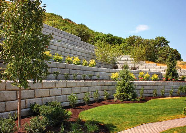
Fig. 2.15. Tiered PMB wall installation examples.
In design, lower tiers must be able to support extra loading from upper tiers and any supported soil, structures, and surcharge loads. The impact of upper tiers on lower tiers is reduced as the distance between the tiers increases.
Many wall designers assume that the impact of the upper tier on a lower tier is small when they are separated by a distance of at least twice the height of the lower tier (measured from the back of the lower tier to the front of the upper tier). Some of this is because the angle be tween the walls is about 27 degrees (arctangent of H/2H), which is less than the internal angle of friction for many soils. Another reason is that both Coulomb and Boussinesq calculations show that the pressure from the upper tier on the lower tier is relatively small at an offset of 2H or greater. An example is shown in figure 2.16.
28 DESIGN INPUTS PRECAST MODULAR BLOCK DESIGN MANUAL VOLUME 1: GRAVITY WALLS
Fig. 2.16. Changes to the surcharge pressure on a lower tier wall from an upper tier with increasing setback between tiers.
Figure 2.16 was prepared by running Boussinesq pressure distribution and graphical Coulomb calculations for (2)10 foot (3 m) high walls retaining a granular material with an effective in ternal angle of friction of 30° and a unit weight of 120 pounds per cubic foot (1,920 kilograms per cubic meter). It shows how increasing the distance between wall tiers reduces the impact of the upper tier on the lower tier.
The impact of the tiered walls on the overall (or global) stability of the slope needs to be care fully investigated as it is often the critical failure mechanism for tiered walls. Overall stability should be evaluated for each tier individually and then for the entire slope containing all tiers.
29DESIGN INPUTS PRECAST MODULAR BLOCK DESIGN MANUAL VOLUME 1: GRAVITY WALLS
30 DESIGN INPUTS
PRECAST MODULAR BLOCK DESIGN MANUAL VOLUME
1:
GRAVITY WALLS
CHAPTER 3.0 LOADS ON THE WALL
3.1. OVERVIEW OF STABILIZING AND DESTABILIZING FORCES
Gravity PMB walls use the weight of the wall to support retained soil and any additional loads. It can be useful to describe forces acting on the wall as either stabilizing or destabilizing.
Forces that act on the wall and attempt to move it are considered destabilizing forces. Common destabilizing forces include:
• Supported earth (horizontal component)
• Live load surcharge (horizontal component)
• Weight of buildings or other supported structures (horizontal component)
• Some or all of the weight of upper walls in multi-tiered wall installations
• Hydrostatic pressure
• Impact loads from traffic barriers
• Seismic loads
• Forces from fences and railings that are supported by the wall
Examples of destabilizing forces are shown in Figure 3.1.
Fig. 3.1. Examples of destabilizing forces on a PMB wall.
31LOADS ON THE WALL PRECAST MODULAR BLOCK DESIGN MANUAL VOLUME 1: GRAVITY WALLS
Forces that act on the wall and work to keep it in place are considered stabilizing forces. Com mon stabilizing forces include:
• Weight of PMB units (including any infill material)
• Weight of supported soil wedges that act with the PMB units
• Supported earth (vertical component)
• Live load surcharge (vertical component)
Examples of stabilizing forces are shown in Figure 3.2.
Fig. 3.2. Examples of stabilizing forces on a PMB wall.
While these classifications help us understand forces acting on the wall, they are not intended as explicit definitions, nor does a force need to be one or the other. There may be instances when a normally stabilizing force achieves a destabilizing effect. Further, inclined forces, such as the earth pressure acting on the back of the wall in a coulomb earth pressure calculation, can be divided into horizontal and vertical components and the same force will have both de stabilizing and stabilizing components. It is the responsibility of the wall designer performing stability analysis to determine which forces are present and identify how they may act on a wall.
3.2. DETERMINATION OF EARTH PRESSURE ACTING ON A WALL
The single most significant factor impacting the design of a retaining wall is how much pressure the retained soils exert on the wall. Not surprisingly, more than one method may be used to calculate this pressure. The most common methods include equivalent fluid pressure, Rankine, Coulomb, log-spiral failure wedge, and general limit equilibrium. It is not the goal of this manual to provide an exhaustive review of earth pressure theory. Instead, it will review basic concepts and focus on how they apply to current PMB wall design.
3.2.1. Equivalent Fluid Pressure
One of the simplest methods to calculate earth pressure on a retaining wall is equivalent fluid
32 LOADS ON THE WALL PRECAST MODULAR BLOCK DESIGN MANUAL VOLUME 1: GRAVITY WALLS
pressure. In this method, retained soils are assumed to act like a fluid. Different unit weights are proposed for various types of soil, with highly permeable, coarse-grained granular soils such as clean sands or gravel possessing the lowest equivalent fluid weights and medium or stiff clays having the highest equivalent fluid weights. Figure 3.3 shows equivalent fluid weights presented by Terzaghi and Peck (1967).
Fig. 3.3. Equivalent fluid pressures recreated from Terzaghi and Peck, 1967.
Pressure at any point on the wall can be calculated by multiplying the equivalent fluid weight by the depth below the ground surface.
(3.1) where
p = pressure on the wall at a particular elevation (lb/ft2) or (kPa) γequiv = fluid weight (lb/ft³) or (kN/m³)
Depth = distance below ground surface at that elevation (ft) or (m)
Pressure on the wall increases linearly with depth. If the pressure behind the wall is drawn graphically, the resulting pressure diagram would be as shown in Figure 3.4.
33LOADS ON THE WALL PRECAST MODULAR BLOCK DESIGN MANUAL VOLUME 1: GRAVITY WALLS
Fig. 3.4. Equivalent fluid pressure on a wall.
The total force on the wall will be equal to the area of the pressure diagram shown in Figure 3.4 and can be calculated as:
(3.1) where F = lateral force on the wall (lb/ft) or (kN/m)
γequiv = equivalent fluid weight (lb/ft³) or (kN/m³) H = wall height (ft) or (m)
Since the pressure diagram is triangular, the total force on the wall can be assumed to act at one third of the wall height, which is the elevation of the centroid of the triangular pressure distribution.

Some geotechnical reports will include recommended equivalent fluid pressure values for a particular site. The authors of this manual prefer more detailed information for the supported soils.
3.2.2. Earth Pressure Coefficients
Geotechnical engineering often uses the concept of earth pressure coefficients to describe the relationship between vertical stress in the soil to resultant earth pressure acting on the wall. In equation form, earth pressure coefficients can be defined as shown.
(3.3)
where k = earth pressure coefficient (subscripts A, P, and 0 are used to clarify the earth pressure as active, passive, or at-rest)
σe = resultant earth pressure on the wall
v = vertical stress in the soil
Figure 3.5 demonstrates the use of earth pressure coefficients to determine forces on a wall for the simplified case of a vertical wall with no additional surcharge loading. The vertical stress in the soil is found by multiplying the depth from ground surface by the unit weight of the
34 LOADS ON THE WALL PRECAST MODULAR BLOCK DESIGN MANUAL VOLUME 1: GRAVITY WALLS
σ
soil. Pressure on the wall is determined by multiplying the vertical stress by the earth pressure coefficient. The force on the wall is equal to the area of the earth pressure diagram. Applica tion of earth pressure coefficients will be further demonstrated throughout this manual and appendices, especially the example problems and graphical Coulomb solutions.
Fig. 3.5. Earth pressure coefficients.
It is worth noting that, despite common usage, earth pressure coefficients are not necessarily the ratio of horizontal to vertical stress. For example, Coulomb earth pressure theory includes a vertical component from friction acting on the back of the wall which is included in the earth pressure coefficient.
3.2.3. Failure Plane Theories

Another type of earth pressure theory is commonly referred to as failure wedge theory. Failure wedge theory is based on soil being in a state of plastic equilibrium. Effectively, the soil is on the verge of failure. Weight of the supported soil is resisted by shear strength of the soil and additional stability provided by the wall.
Failure wedges can be generated for walls moving away from or into supported soils. The con dition where the wall is moving away from the soil is called the “active condition”. In the active condition, vertical stress in the soil is greater than the horizontal stress. Conversely, “passive condition” describes the wall moving into the soil. In the passive condition, the horizontal stress in the soil is greater than the vertical stress. A condition also exists whereas the wall is not moving at all. This condition – “at-rest” – is discussed later in this chapter. The at rest condition is based on the elastic properties and stress history of the soil (instead of plastic equilibrium).
Wall movement is required to mobilize the soil’s frictional strength. The amount of movement required for soil to achieve the active and passive conditions varies. Winterkorn and Fang (1975) estimate the wall needs to rotate about the base and/or translate between 0.001H and 0.005H to develop active pressure and approximately 0.05H to develop passive pressure. NAVFAC 7.2 (1986) and FHWA-NHI-07-071 (2008) publish similar findings that show the amount of move ment (both translation and rotation) required to fully mobilize the earth pressure. The graphic has been recreated here in Figure 3.6.
35LOADS ON THE WALL PRECAST MODULAR BLOCK DESIGN MANUAL VOLUME 1: GRAVITY WALLS
Fig. 3.6. Effect of wall movement on wall pressures.
The three most common failure wedge theories are Rankine, Coulomb, and Log Spiral.
3.2.3.1. Rankine Earth Pressure Theory
In 1857, Scottish engineer William Rankine developed a theory of plastic equilibrium for soils (Terzaghi and Peck, 1967), which concerned the relationship of horizontal and vertical pressure due to lateral expansion or contraction of a semi-infinite mass of soil and acted on by no other force than gravity.
Rankine’s theory of plastic equilibrium was expanded to determine the earth pressures acting on retaining walls. To be applicable, the soil must deform sufficiently to mobilize the shear strength and the wall must be smooth.
In the case of the wall deflecting slightly away from the soil (and the vertical stress in the soil being greater than the horizontal stress), the soil is said to be in the active condition. The co efficient of active earth pressure, kA, can be defined as: (3.4)
where φ’ = effective internal friction angle of the soil
When the wall is forced into the soil (and the horizontal stress in the soil greater than the vertical stress), the soil is in the passive condition. The coefficient of passive earth pressure, kP can then be defined as:
(3.5)
Terzaghi and Peck (1967) includes diagrams of sand contained in an idealized rectangular box that illustrate the active and passive Rankine states. These diagrams are recreated in Figure 3.7.
36 LOADS ON THE WALL PRECAST MODULAR BLOCK DESIGN MANUAL VOLUME 1: GRAVITY WALLS
Fig. 3.7. Local active and passive Rankine states. Based on Terzaghi and Peck (1967).
In the active condition, the wall on the left side of the box is assumed to move outward from the soil (to the left), allowing enough deformation in the soil to develop an active Rankine state within the soil wedge. As the wall moves out, the soil wedge slides downward and outward along a plane at an angle of 45° + φ'/2. In the passive condition, the wall on the left side of the box is assumed to move into the soil (to the right) far enough for the soil to develop a passive Rankine state within the soil wedge. As the wall moves inward, the soil wedge slides upward and inward along a plane at an angle of 45° - φ'/2.
In practice, retaining walls are not perfectly smooth, so the Rankine results tend to overpredict the active pressure and underpredict the passive pressure. One case where the Rankine condi tion does apply, however, is that of a cantilever retaining wall with a long heel. This case allows the shear planes to fully develop as shown in Figure 3.8.
3.2.3.2.
Coulomb Earth Pressure Theory
In 1776, prior to Rankine’s work on plastic equilibrium, Charles Coulomb, a French military en gineer, developed a method to compute earth pressures acting on retaining walls. Coulomb’s theory essentially determines the force exerted by a wedge of soil, sliding along a failure plane, against a wall that is supporting it. Coulomb assumes a linear failure plane and a linear ground surface. It explicitly accounts for friction between the soil and wall, and can account
37LOADS ON THE WALL PRECAST MODULAR BLOCK DESIGN MANUAL VOLUME 1: GRAVITY WALLS
Fig. 3.8. Rankine active failure planes for a cantilever wall with a long heel.
for sloping backfill. Similar to Rankine’s theory, Coulomb’s supposition requires that the wall move sufficiently to mobilize the shear strength of the soil. Bowles (1996) does an excellent job of describing the derivation of the Coulomb earth pressure coefficients in a step-by-step process. An abbreviated version follows. The interested reader is encouraged to review Bowles (1996) or related texts for more details.
The Coulomb active failure condition for a cohesionless soil starts with an assumed failure plane behind the wall at an angle α. The weight of the wedge of soil defined by the ground surface, back of wall, and failure plane is W. The weight of the soil wedge is resisted by the soil below the failure plane and by the wall. For the wedge to form, the soil must fail in shear along the plane defined by the angle α. Coulomb also considers friction between the back of the wall and the retained soil. The Coulomb active failure condition is shown in Figure 3.9.
Fig. 3.9. Coulomb active failure condition.
The shear force along the failure plane is equal to the normal force, N, multiplied by the tangent of the effective internal angle of friction of the retained soil, φ'. Similarly, the friction force on the back of the wall is equal to the force, F, multiplied by the tangent of the angle of friction between the back of the wall and the retained soil, δ.
To simplify, the normal force N and the shear force along the failure plane can be combined into a reaction force R that acts at the angle φ' from perpendicular to the failure wedge. The force on the wall F and the friction between the back of the wall and the retained soil can also be combined into the active earth pressure force PA that acts at the angle δ from perpendicular to the back of wall. The Coulomb active failure condition can be redrawn as shown in Figure 3.10.
38 LOADS ON THE WALL PRECAST MODULAR BLOCK DESIGN MANUAL VOLUME 1: GRAVITY WALLS
Fig. 3.10. Coulomb active failure condition (simplified).
The geometry of the active soil wedge is shown in Figure 3.11.
Fig. 3.11. Coulomb active soil wedge.
The weight of the active soil wedge is equal to the unit weight of the soil multiplied by the area of the active wedge. The Law of Sines and the formula for the sine of the difference of two angles can be used on the triangle shown in Figure 3.11 to determine the area of the failure wedge. The weight of the active soil wedge can then be written as:
where
= height of wall (ft) or (m)
= unit weight of retained soil (lb / cubic ft) or (kN / cubic meter)
= angle of back face of wall to the horizontal (degrees)
= angle of the backslope to the horizontal (degrees)
39LOADS ON THE WALL PRECAST MODULAR BLOCK DESIGN MANUAL VOLUME 1: GRAVITY WALLS
(3.6)
H
γ
θ
β
α = angle of the failure plane in the retained soil (degrees)
The active earth pressure is a function of the weight of the active soil wedge, the reaction force on the back of the wall, the friction between the retained soil and the back of the wall, the normal force on the failure plane, and the shear forces generated along the failure plane. A vector diagram of the forces and their direction are shown in Figure 3.12.
Fig. 3.12. Coulomb force vectors.
For a given soil wedge, the weight of the wedge W is known. The angles α, δ, θ, and φ' are also known. Therefore, we can use The Law of Sines on the force vector diagram to write the following equation for the active earth pressure: (3.7) where W = weight or wedge of soil (lb) or (kN)
α = angle of the failure plane in the retained soil (degrees) φ' = effective internal friction angle of the soil (degrees) θ = angle of back face of wall to the horizontal (degrees)
δ = angle of friction between the back of the wall and the retained soil (degrees)
Equations (3.6) and (3.7) can be combined and written in terms of PA (3.8)
For a given problem, H, γ, φ', β, δ, and θ are constant and the only variable that remains in PA is α. If we take the derivative of PA in Equation 3.8 with respect to α and set it equal to zero, we can solve for the value of α that produces the largest PA. This value of α is the angle of the failure wedge and the maximum value PA produced with this failure wedge is the active earth pressure on the wall. The math gets complicated, but thankfully several authors worked out the solution and subsequently provided a formula for the earth pressure coefficient, kA. AASHTO (2020) provides equations 3.11.5.3-1 and 3.11.5.3-2 for kA, which can be combined and written as: (3.9)
40 LOADS ON THE WALL PRECAST MODULAR BLOCK DESIGN MANUAL VOLUME 1: GRAVITY WALLS
where
φ' = effective internal angle of friction of the retained soil (degrees)
θ = angle of back face of wall to the horizontal (degrees)
δ = angle of friction between the back of the wall and the retained soil (degrees)
β = angle of the backslope to the horizontal (degrees)
The value of δ depends on how smooth or rough the interface is between the back of the wall and the supported soil. Many designers use a value of ⅔ of φ, which is a fairly common as sumption for a concrete wall with a constant batter. However, PMB walls are actually made from stepped units often featuring different widths. AASHTO (2020) recommends a value of 0.75 φ for prefabricated modular walls with an average pressure surface for stepped modules (Table C3.11.5.9-1). The wall designer will need to exercise professional judgment when deciding on an appropriate value of δ to use.
It is interesting to note that for situations where θ = 90° and δ = β = 0°, the Coulomb formulas simplify to Rankine’s equations.
In addition to equation (3.9), Culmann and others have proposed methods to solve Coulomb graphically using vectors. Graphical solutions can be quite useful to determine earth pressures from projects with complicated geometries such as an irregular ground surface on the top of the wall. To conduct a graphical solution, multiple failure surfaces are evaluated. The failure surface that results in the highest active earth pressure is identified as the critical failure plane. Detailed CAD solutions can be extremely accurate and return the exact same value as a cal culated solution. A graphical solution of Coulomb with several worked examples is offered in "Appendix: C".
3.2.3.3. Log Spiral Earth Pressure Theory
Coulomb’s theory assumes a straight failure surface. In reality, particularly considering wall friction, the failure surface is curved. The effect is minimal for the active condition, but can be significantly unconservative for the passive condition with high soil-wall interface friction (δ) values. Terzaghi and Peck (1967) suggest accounting for the curved failure surface for δ > φ/3. AASHTO (2020) states that the value of wall friction should not be greater than φ/2 when using wedge theory (i.e. Coulomb method) to determine passive pressure.
Logarithmic-spiral surfaces are more accurate approximations for the passive failure surface. The general shape of a logarithmic-spiral failure surface is shown in Figure 3.13.
41LOADS ON THE WALL PRECAST MODULAR BLOCK DESIGN MANUAL VOLUME 1: GRAVITY WALLS
Fig. 3.13. Logarithmic-spiral failure surface.
Computer programs are available to solve for kp and Pp. In addition, NAVFAC 7.2 (1982) and AASHTO (2020) offer charts that provide a value of kp for several conditions.
3.2.3.4.
General Limit Equilibrium
Coulomb’s method is essentially a derivation of a limit equilibrium solution to lateral earth pres sure problems, with the assumption of a planar failure surface. As discussed previously, failure surfaces for both the active and passive states are actually curved, not straight. In addition, Coulomb’s equations are limited to simplified geometry. Limit equilibrium methods, which are readily available in commercial slope stability programs, are well-suited to solving for lateral earth pressures. This method is discussed by Janbu (1957) in Earth Pressures and Bearing Capacity Calculations by Generalized Procédure of Slices and Rahardjo and Fredlund (1984)
General limit equilibrium method for lateral earth force.
The method can be implemented by using any limit equilibrium slope stability program. The geometry is defined, stopping at the back of the wall, and soil stratigraphy is added. Ground water, pseudostatic seismic forces, and external loads/surcharges can be included (these will be discussed more in following sections). The resultant earth pressure load is added as a line load, acting against the soil mass. It is typically assumed that the load acts at an inclination equal to the soil-wall interface friction angle from the direction normal to the back of the wall and that the location of the resultant acts at a set distance such as H/3 or 0.4H from the base of the wall. The line load is given a trial value and the critical failure surface search is completed. The line load value is revised until the resulting factor of safety value is equal to one. The GLE method is shown graphically in figure 3.14.
42 LOADS ON THE WALL PRECAST MODULAR BLOCK DESIGN MANUAL VOLUME 1: GRAVITY WALLS
Fig. 3.14. Computer solution of general limit equilibrium method for determining earth pressure on a retaining wall.
The coefficient of active earth pressure, kA, can be derived from the resultant - assuming a triangular earth pressure distribution - using the following formula: (3.10) where PA = earth pressure force acting on the retaining wall determined through an iterative computer solution (lb/ft) or (kN/m) H = height of wall in (ft) or (m) γ = unit weight of retained soil (lb/ft3) or (kN/m3)
Comparisons between earth pressures computed using the GLE method and those with con ventional methods, such as Coulomb, show good agreement.
3.2.4. At-Rest Earth Pressure
In scenarios where the wall is rigid, no movement can occur to mobilize the shear strength of the soil. Earth pressure on the wall is said to be at-rest. At-rest pressure is a function of the elastic properties of the soil and also represents the state of stress in a soil in a free-field condition as if there is no wall or excavation as shown in Figure 3.15.
43LOADS ON THE WALL PRECAST MODULAR BLOCK DESIGN MANUAL VOLUME 1: GRAVITY WALLS
Fig. 3.15. At-rest soil in a free field condition.
The coefficient of earth pressure for at-rest is designated by the subscript 0, and is often ap proximated by a simplified version of an equation proposed by Jaky as presented in Bowles (1996) and others:
(3.11) where φ' = effective internal angle of friction of the retained soil (degrees)
Coduto (2001) provides the following formula to estimate k0 to account for the stress history of the soil when the soil is overconsolidated:
(3.12) where φ' = effective internal angle of friction of the retained soil (degrees) OCR = overconsolidation ratio of the retained soil (unitless)
While it is uncommon for a PMB wall to be designed to support at-rest earth pressure, there are some applications where designers might use it. A prime example is a wall that supports a structure or a critical utility. A second instance where at-rest earth pressure may be used occurs when the designer wishes to account for some resistance from soil in front of the wall near the toe but does not want to design for the full amount of movement required to completely mobilize passive earth pressure.
3.2.5. Earth Pressure for This Manual
For most applications, Coulomb is used to calculate active earth pressure and Jaky is used to determine at-rest earth pressure. Either Rankine or Log Spiral is used to calculate passive earth pressure. Coulomb, Jaky, and Rankine will be used in this manual for active, at-rest, and passive pressure respectively.
3.2.6. Back-of-Wall Location
The earth pressure theories presented above all assume a back-of-wall condition. For Rankine, the back of wall is assumed to be vertical and frictionless. For Coulomb, the back of wall is assumed to be a constant surface at an angle θ from horizontal and have an interface friction
44 LOADS ON THE WALL PRECAST MODULAR BLOCK DESIGN MANUAL VOLUME 1: GRAVITY WALLS
angle of δ between the back of the wall and the retained soil. In practice, PMB walls can have different back-of-wall conditions and the designer needs to decide how to best approximate the back of wall to determine earth pressures. Some example PMB walls with different backof-wall configurations are shown in Figure 3.16.
Fig. 3.16. PMB walls with different back of wall conditions.
3.2.6.1.
Constant Batter Walls
Walls that are constructed with PMB units of the same size and the same unit-to-unit setback throughout the entire wall cross-section are typically approximated as a constant back of wall. The back of wall in this case follows a line drawn through the back heel of each PMB unit. The angle θ is easily calculated from the unit height and setback. Long-term practice for constant batter walls is to use a value of ⅔ φ' for δ. An example of a PMB wall with a constant batter back of wall is shown in Figure 3.17.
45LOADS ON THE WALL PRECAST MODULAR BLOCK DESIGN MANUAL VOLUME 1: GRAVITY WALLS
Fig. 3.17. PMB wall with constant batter back of wall and associated pressure diagrams.
A detailed example with a constant batter back of wall is presented in Example 1 (In Appendix: A and Appendix: B).
3.2.6.2. AASHTO Stepped Modules
A benefit common to gravity PMB walls is the ability to use PMB units with different heights and widths in the same cross section. Depending on the particular units used, some wedges of soil may act with the wall. It is obvious that this type of wall doesn’t match the idealized back of wall assumed in the derivation of the Coulomb earth pressure coefficients and would not be well represented by a constant batter back of wall. In these cases, the designer needs a different method to approximate the back of wall.
One approach is detailed in AASHTO (2020) for use with Prefabricated Modular Walls. Spe cifically, AASHTO Figure 3.11.5.9-2 shows a way to approximate a linear back of wall for pre fabricated modular walls with irregular pressure surfaces. Using this approach, a straight line is drawn from the back, bottom corner of the bottom PMB unit to the back, top corner of the top PMB unit. This line is intended to approximate the back of wall when performing Coulomb earth pressure calculations. The angle of this line from horizontal is used as θ. AASHTO Table 3.11.5.9-1 provides a recommended minimum wall friction angle δ for an average pressure surface approximated for stepped precast modules of 0.75 φ'.
Many designers prefer this approach because it makes sense and is easy to perform. However, the straight line used to represent the back of wall with this method is only an approximation of the average pressure surface on the back of the wall. This line does not define the soil wedges (if any) that are supported by and act with the PMB units to resist destabilizing forces. Designers must use sound engineering judgment to select a separate line (or lines) to divide the soil that is assumed to act, as part of the wall, from the retained soil.
46 LOADS ON THE WALL PRECAST MODULAR BLOCK DESIGN MANUAL VOLUME 1: GRAVITY WALLS
A PMB wall analyzed as a precast modular wall with an irregular pressure surface with a back of wall approximated with a straight line is shown in Figure 3.18.
Fig. 3.18. PMB wall with an approximated straight line back of wall and associated pressure diagrams.
A detailed example with an approximated back of wall is presented in Example #2 (In Appendix: A and Appendix: B).
3.2.6.3. Skewed Back of Wall
Another approach is to define a skewed back of wall as shown in German Standards DIN 4085:2017-08, (2017) Subsoil - Calculation of Earth Pressure and used in design platforms like Fine Software’s GEO 5. This method has been used very successfully on Redi-Rock PMB walls for many years.
47LOADS ON THE WALL PRECAST MODULAR BLOCK DESIGN MANUAL VOLUME 1: GRAVITY WALLS
In the skewed back-of-wall approach, the wall is divided into different zones. The back of wall follows either the back of the PMB units or a soil wedge (in areas where the wall section tran sitions from wider to narrower units).
The skewed back-of-wall approach is best described through an example, shown in Figure 3.19.
Fig. 3.19. Example PMB wall with skewed back of wall.
For our example, the wall can be divided into 3 distinct zones. Zone 1 encompasses the section of the wall featuring a constant batter and runs from Point A to Point B. Zone 2 follows the soil wedge that forms as the wall transitions from a wider PMB unit to narrower PMB unit and runs from Point B to Point C. Zone 3 includes the back of the bottom PMB unit and runs from Point C to Point D.
The angle of the soil wedge will depend on the particular strength parameters of the soil and the wall geometry at that point. The angle of the soil wedge for cohesionless soil is shown in Figure 3.20 and can be calculated from the following iterative formulas:
48 LOADS ON THE WALL PRECAST MODULAR BLOCK DESIGN MANUAL VOLUME 1: GRAVITY WALLS
(3.13) (3.14)
where
αi = angle of the failure plane that creates the soil wedge (from vertical) (degrees)
φ' = effective internal angle of friction of the retained soil (degrees)
δ = angle of friction between the back of the wall and the retained soil (degrees)
β = angle of the backslope to the horizontal (degrees)
Fig. 3.20. Soil wedge that forms when a wall transitions from a wider to a narrower section.
Once the back of wall has been divided into zones, an active earth pressure coefficient is defined for each zone. A diagram of the vertical and horizontal pressure is drawn assuming that the entire wall has the same back-of-wall conditions as the zone in question. This is done for our example PMB wall in Figures 3.21, 3.22, and 3.23.
49LOADS ON THE WALL PRECAST MODULAR BLOCK DESIGN MANUAL VOLUME 1: GRAVITY WALLS
Fig. 3.21. Back of wall and pressure diagrams if the entire back of wall was like Zone 1.
Fig. 3.22. Back of wall and pressure diagrams if the entire back of wall was like Zone 2.

50 LOADS ON THE WALL
PRECAST MODULAR
BLOCK DESIGN MANUAL VOLUME 1: GRAVITY WALLS
Fig. 3.23. Back of wall and pressure diagrams if the entire back of wall was like Zone 3.
A composite pressure diagram is created by overlaying the individual pressure diagrams with their particular zone. The back of wall and composite pressure diagram for our example is shown in Figure 3.24.
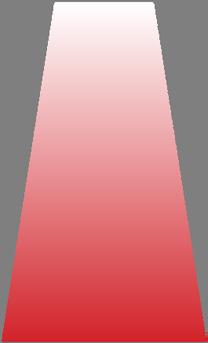
Fig. 3.24. Skewed back of wall and composite pressure diagrams for example PMB wall.

51LOADS ON THE WALL
PRECAST MODULAR BLOCK DESIGN MANUAL
VOLUME 1:
GRAVITY WALLS
The force acting on the wall is equal to the area of the composite pressure diagram. Unlike the case for an idealized back of wall, the pressure diagram is irregular (not triangular) and each zone has its own back of wall angle θ and interface angle of friction δ (instead of a single value of each for the entire wall). As a result, a weighted average calculation is required to determine the horizontal and vertical components of the force on the wall and the point of application for that force.
The horizontal component of the force on a wall with n zones is calculated as: (3.15) where
Pa i = area of the lateral pressure diagram of zone i
θi = angle of back face of wall to the horizontal in zone i (degrees)
δi = angle of friction between the back of the wall and the retained soil in zone i (degrees)
The vertical component of the force on a wall with n zones is calculated as: (3.16) where Pa i = area of the lateral pressure diagram of zone i θi = angle of back face of wall to the horizontal in zone i (degrees)
δi = angle of friction between the back of the wall and the retained soil in zone i (degrees)
The horizontal distance (x-direction) from the toe of the wall to point of application of the force on the skewed back of wall is calculated as: (3.17) where Pa i = area of the lateral pressure diagram of zone i Pav = vertical component of the force on a wall with n zones calculated from (3.16) θi = angle of back face of wall to the horizontal in zone i (degrees) δi = angle of friction between the back of the wall and the retained soil in zone i (degrees)
Xi = horizontal distance of the toe to the back of the wall at the elevation of the centroid of the lateral pressure diagram of zone i
The vertical distance (z-direction) from the toe of the wall to point of application of the force on the skewed back of wall is calculated as: (3.18)
where
Pa i = area of the lateral pressure diagram of zone i Pah = horizontal component of the force on a wall with n zones calculated from (3.15)
52 LOADS ON THE WALL PRECAST MODULAR BLOCK DESIGN MANUAL VOLUME 1: GRAVITY WALLS
θi = angle of back face of wall to the horizontal in zone i (degrees)
δi = angle of friction between the back of the wall and the retained soil in zone i (degrees)
Zi = vertical distance of the toe to elevation of the centroid of the lateral pressure diagram of zone i
As this example demonstrates, a skewed back of wall depends on the specifics of the wall section and will vary with every different PMB wall. The intent is to have the back of wall follow either the PMB units or a soil wedge. The approach outlined above can be used for a wall with few or many different back of wall zones.
A detailed example with a skewed back of wall is presented in Example 3 (In Appendix: A and Appendix: B).
3.3. SURCHARGE LOADS
Neither Rankine or Coulomb include provisions to specifically account for surcharge loads that are supported by the wall. Wall designers can use different approaches depending on where the loads are located.
3.3.1. Uniform Loads
If the loading is spread out enough that it may be considered continuous, surcharge loads can be accounted for by approximating them with an equivalent height of soil.
Wall designers use fairly common values to represent different surcharge loads. For example, AASHTO publishes different design vehicles. The truck AASHTO uses for H-20 loading has two axles, a total weight of 40,000 lb (178 kN), and a footprint of approximately 16 ft x 10 ft (4.9 m x 3.0 m). Such a truck would generate an average contact pressure of 250 lb / square foot (12.0 kPA). Assuming a unit weight of approximately 125 lb / cubic foot (19.6 kN / cubic meter), the contact pressure of the H-20 design truck is equivalent to the vertical pressure at the bottom of about 2 ft (0.6 m) of soil. If the wall supports traffic loads, such as a parking lot or roadway, it is possible that several trucks would be close enough to each other that the impact on the wall would be similar to a surcharge load of 250 lb / square foot (12.0 kPa) spread continuously on the entire ground surface behind the wall.
The vertical stress or pressure in the retained soil behind an example wall that supports a uni form surcharge load, often called a live load (LL) due to the transient nature of the traffic, is shown in Figure 3.25. Coulomb earth pressure coefficients can be used to convert the vertical
53LOADS ON THE WALL PRECAST MODULAR BLOCK DESIGN MANUAL VOLUME 1: GRAVITY WALLS
pressure to force on the retaining wall as shown in Figure 3.26.
Fig. 3.25. Vertical stress in the retained soil for a wall with a live load surcharge.
Fig. 3.26. Forces on a retaining wall with a live load surcharge.
Although an equivalent height of soil is used to include the effect of surcharge loads, common practice is to separate the earth pressure and the surcharge loading in design calculations. Furthermore, the distinction between live loads and other surcharge loads is made to allow designers to use different load factors to account for variations in certainty and reliability of the loads.
3.3.2. Offset Loads
Loads that are offset from the wall are not continuous and are not easily modeled with an equivalent height of soil. It is very common for wall designers to use the theory of elasticity to convert offset surcharge loads to lateral pressures on the wall. AASHTO, AREMA, and others include equations based on Boussinesq Theory to convert strip, line, and point loads to lateral pressures.


The Boussinesq equation for horizontal force at a point on the wall due to an offset strip load surcharge from AASHTO (2020) is provided in equation 3.19 and shown in Figure 3.27.
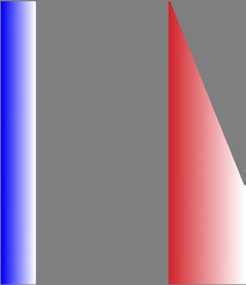
54 LOADS ON THE WALL PRECAST MODULAR BLOCK DESIGN MANUAL VOLUME 1: GRAVITY WALLS
3.4.
where
ΔPH = pressure on the back of the wall at a specific point (lb/ft2 or kPa)
p = uniform load intensity strip parallel to wall (lb/ft2 or kPa)
α = angle specified in Figure 3.27 (radians)
δ = angle specified in Figure 3.27 (radians)
Fig. 3.27. Horizontal pressure on wall from an offset uniformly loaded strip.
A few items of note:
• The Boussinesq equation is based on the theory of elasticity. It should not be confused with Rankine and Coulomb earth pressures which are based on the theory of plastic equilibrium.
• Equation (3.19) computes horizontal stresses in the soil. Other derivations are available for vertical stress, as well as for different surface load configurations.
• The active earth pressure coefficient kA is not used.
• Forces are not assumed to act at the angle δ to the back of the wall.
• Equation (3.19) is based on rigid, unyielding walls and may be very conservative for more flexible PMB gravity walls.
An alternate approach to using the Boussineq equation when determining the impact of offset strip loads on the wall would be to use a graphical Coulomb solution. The graphical solution does not require as many simplifying assumptions as were used to develop Equation (3.9); therefore, it can easily account for the offset strip load. The graphical Coulomb solution is detailed in "Appendix: C"
HYDROSTATIC LOADS
Water impacts the loading on a wall in several ways. Water exerts a hydrostatic force on the wall and produces buoyant forces, that reduce the effective weight of the soil.
Pressure exerted on a wall from water can be calculated by:
55LOADS ON THE WALL PRECAST MODULAR BLOCK DESIGN MANUAL VOLUME 1: GRAVITY WALLS (3.19)
(3.20)
where
pw = pressure from water (lb/ft2 or kPa) γw = unit weight of water (lb/ft3 or kN/m3) h = depth of water
There is no friction between the water and the retaining wall so the water pressure on a wall acts horizontally at the elevation of the centroid of the pressure diagram of the water. Water pressure is not multiplied by an earth pressure coefficient.
Active earth pressure on a wall from the retained soil above the elevation of groundwater is calculated using the moist unit weight of the soil. Below the groundwater elevation, the active earth pressure is calculated using the buoyant unit weight of the soil which is the saturated unit weight of the soil minus the unit weight of water.
Any water in front of the wall will also apply pressure to the wall. If the surface water and groundwater are the same elevation, they will cancel out one another. If the surface water is lower than the groundwater, as in the case of rapid drawdown, the groundwater will put increasing pressure on the wall until it reaches the elevation of surface water, at which point hydraulic pressure on the wall will no longer increase but remain constant.
An example of the pressure on a retaining wall with groundwater and surface water present are shown in Figures 3.28 and 3.29.
Fig. 3.28. Example of retaining wall with groundwater in retained backfill.
Fig. 3.29. Example of retaining wall with groundwater in retained backfill and surface water in front of wall.
56 LOADS ON THE WALL PRECAST MODULAR BLOCK DESIGN MANUAL VOLUME 1: GRAVITY WALLS
3.5.
SEISMIC LOADS
Impacts from earthquakes are complex. Wall design generally involves adding a horizontal load from the shaking motion of the earthquake and an inertial force from the shaking of the wall itself to the static wall analysis. Load combinations and factors of safety or load and resistance factors are modified for the seismic conditions.
Seismic analysis is beyond the scope of this volume. The reader is referred to other texts such as AASHTO (2020) to evaluate the impact of seismic events on gravity PMB retaining walls.
3.6. BARRIER LOADS
It is quite common for a retaining wall to include railings or barriers to protect pedestrians or vehicles on the top of the retaining wall. While less common, some walls include barriers at the bottom of the wall to prevent impact from vehicles into the wall itself. The wall designer must include loads from any railings or barriers in the stability analysis of the wall. Design loads for general barrier types are discussed below. Additional information on barriers may also be found in Section 5.6.
3.6.1. Pedestrian Handrail Loads
The International Building Code (2021), ASCE Standard 7-16 (2017), and AASHTO LRFD Bridge Design Specifications (2020) detail pedestrian handrail load requirements. AASHTO (2020) requires that railings be designed to resist a 200 lb (0.9 kN) concentrated load and a uniform load of 50 lb / ft (0.7 kN / m) applied at 42 in. (1.07 m) above the surface. ASCE Standard 7-16 (2017) and the International Building Code (2021) contain the same design loads; however, ASCE does not require the concentrated load and uniform load to be applied at the same time.
3.6.2. Fences
Fences, particularly tall or solid fences, must be designed for wind loads in addition to other loads that may be applied. Each application will be unique and will evaluate considerations like composition of the fence, post spacing, height, and local wind speeds. ASCE Standard 7-16 (2017) serves as an excellent resource with which to calculate wind loads. Fence loads will be applied to PMB walls at the post locations and will include all the forces on the fence from the midpoint between posts in both directions.
3.6.3. Post-and-Beam Guardrails
Post-and-beam guardrails are primarily used parallel to traveled roadways to keep vehicles from leaving the road surface. Impacts are often skewed at angles of 45° or less. Post-and-beam guardrails are also used in low speed applications where impacts can be at angles up to 90°.
To date, the authors have been unable to locate any data of the impact to the retaining wall when loads are transferred from a vehicle to the post, guardrail, and soil and ultimately through the soil to the retaining wall. It is an exceedingly complicated scenario to measure. Upon impact, posts are either dislodged or broken off. As the impact continues, the steel rail deforms and is placed in tension, transferring load to adjacent posts. A significant portion of the energy from the impact is absorbed by the vehicle, post, and rail. The remaining energy is transferred to the soil and a portion of that energy passes through the soil to the retaining
57LOADS ON THE WALL PRECAST MODULAR BLOCK DESIGN MANUAL VOLUME 1: GRAVITY WALLS
wall. In lieu of specific guidance, many designers will use the AASHTO (2020) requirements for MSE walls and apply them to PMB gravity walls. Specifically, the designers will apply a load of 300 lb/ft (4.4 kN/m) to the back of the wall. This load is commonly assumed to act one third of the way down the buried portion of the post. In general, guardrail posts should be offset at least 3 feet (0.9 m) from the wall to allow for deflection of the guardrail system. This topic is discussed further in Chapter 5.
3.6.4. Traffic Barriers for Highways
AASHTO (2020) provides design guidance for concrete parapet wall and moment slab barriers. Concrete barriers often have a specific shape, such as the FHWA “F” shape or a New Jersey bar rier shape, that has undergone full scale testing. Design requirements are provided for impacts at 6 different test levels. The basic test level is Test Level 3 (TL-3) in which a 4,409 lb (2,000 kg) pickup truck impacts a barrier at 62 mph (100 km/h) and 25 degrees.
Highway barriers have been thoroughly studied for use with MSE walls. NCHRP Report 663, Design of Roadside Barrier Systems Placed on MSE Retaining Walls, contains ample infor mation, including detailed design examples.
NCHRP 663 includes numerical simulations for different sized moment slabs that compare dynamic force from impacts on the barrier to the static equivalent load that would produce a given amount of movement of the slab. In one example, the report shows that a 54,000 lb (240 kN) dynamic load associated with 1 inch (25 mm) movement is approximately equivalent to a 10,000 lb (44.48 kN) static load. As a result, the moment slab in most highway barrier designs is sized to resist a static load of 10,000 lb. After the moment slab size has been determined, the structural capacity of the barrier is designed to resist the dynamic impact load specified in AASHTO for the particular test level. Dynamic transverse loads in AASHTO range from 13,500 to 175,000 lbs (60 to 778 kN) and impact heights range from 18 to 56 inches (457 to 1,422 mm) from the road surface for the 6 different test levels.
The stability of the wall, especially the upper rows of PMB units, must be evaluated including additional forces from vehicle impact. There is no specific guidance for gravity walls, so de signers look to the requirements for MSE walls as reference. With an MSE wall, it is assumed that impact loads are transferred through the barrier and moment slab to the soil and then to the soil reinforcement. AASHTO (2020) and FHWA (2009) require MSE walls be designed with additional static loads in the upper two layers of soil reinforcement when evaluating rupture and pullout capacity of the reinforcement. With gravity walls, there is no soil reinforcement and the designer is left to assume that any forces in the soil would be transferred directly to the wall.
One of the design conditions evaluated for PMB gravity walls should include the vehicle impact load. Similar to the approach used to size the moment slab, internal and external wall stability should be evaluated with the equivalent static load. The full length of the barrier and moment slab between control joints should be used when converting the equivalent static impact load into a unit length of wall load. Due to the large size and significant weight of a typical barrier and moment slab, the extra stability calculations with the impact load do not generally result in noteworthy changes to the wall design.
3.6.5. Traffic Barriers for Buildings and Other Structures
The International Building Code (2021) and ASCE Standard 7-16 (2017) contain provisions for impacts from a passenger vehicle in the design of buildings and other structures.
58 LOADS ON THE WALL PRECAST MODULAR BLOCK DESIGN MANUAL VOLUME 1: GRAVITY WALLS
According to Section 1607.10 of the 2021 International Building Code and Section 4.5.3 of ASCE Standard 7-16, the barrier must resist a single load of 6,000 lb (26.7 kN) in any direction to the barrier system and have sufficient anchorages capable of transferring this load to the structure. For a retaining wall, the critical direction would be perpendicular to the face of the wall. ASCE 7-16 further specifies that the load be applied between 1 ft. 6 in. (460 mm) and 2 ft. 3 in. (686 mm) above the surface and applied on an area not to exceed 12 in. by 12 in. (305 mm by 305 mm). It is interesting to note that applying the findings from NCHRP 663, a 6,000 lb (26.7 kN) static load would correspond to a dynamic load of 30,900 lb (137.4 kN), which is between an AASHTO Test Level 2 and 3 (TL-2 and TL-3).
Many wall designers will use the IBC design requirements for impacts from a passenger vehicle in the design of buildings and other structures for a vehicle impact on a private project where no other design guidance is provided.
59LOADS ON THE WALL PRECAST MODULAR BLOCK DESIGN MANUAL VOLUME 1: GRAVITY WALLS
60 LOADS ON THE WALL
PRECAST
MODULAR BLOCK DESIGN MANUAL VOLUME 1: GRAVITY WALLS
CHAPTER 4.0
STABILITY ANALYSIS
4.1. MODES OF FAILURE
Gravity PMB walls use the weight of the PMB blocks and any supported soil wedges to resist destabilizing forces. Stability of the wall is analyzed by evaluating potential modes of failure. Stability can be classified as external, internal, or overall.
External stability evaluates the entire wall section, from either the bottom of the leveling pad or the bottom of the first row of PMB units to the top of the wall. Potential external stability failure modes requiring evaluation include sliding of the wall (Figure 4.1), overturning of the wall and/or eccentricity of the bearing resistance loads (Figure 4.2), and bearing capacity failure of the foundation soils (Figure 4.3).
Fig. 4.1. External sliding stability.
Fig. 4.3. Bearing capacity of foundation soil.
Fig. 4.2. External overturning stability.
61STABILITY ANALYSIS PRECAST MODULAR BLOCK DESIGN MANUAL VOLUME 1: GRAVITY WALLS
PMB Walls are made from discrete units and are not solid or rigid structures. As a result, stability needs to be analyzed at each row of PMB units. Internal stability evaluates each section from that particular row of PMB units to the top of the wall. Potential internal stability failure modes that must be evaluated include sliding between rows of PMB units (Figure 4.4) and overturning of the upper section of a wall (Figure 4.5)
Fig. 4.4. Internal sliding stability.
Fig. 4.5. Internal overturning stability.
Overall stability is also commonly referred to as “global stability”. Overall, or global stability evaluates the entire slope containing the wall. Potential overall stability failure modes include failure of the slope below, behind, and above the retaining wall. A subset of overall stability calculations is called “internal compound stability” and considers failure of the slope above the wall, with the failure surface passing through the wall. Potential overall and internal compound stability failure modes are shown in Figures 4.6 and 4.7.
Fig. 4.6. Overall or global stability.
62 STABILITY ANALYSIS PRECAST MODULAR BLOCK DESIGN MANUAL VOLUME 1: GRAVITY WALLS
4.2. ALLOWABLE STRESS DESIGN AND LOAD AND RESISTANCE FACTOR DESIGN
When performing a stability analysis, the wall designer must establish criteria to determine if the proposed wall is acceptable to resist the forces that will be acting on it and estimate the reliability of the analysis. The two methods used are Allowable Stress Design (ASD) and Load and Resistance Factor Design (LRFD). Nominal loads and forces, such as the weight of the PMB units and earth pressure force acting on the wall, are calculated for both cases. The difference between ASD and LRFD is what the designer does with the nominal loads.
In Allowable Stress Design, nominal values of the stabilizing forces or moments are divided by nominal values of destabilizing forces or moments to determine a Factor of Safety (FS). If the calculated FS is greater than a minimum value, the wall is considered acceptable to resist that particular failure mode. While specific sources may vary, a range of commonly accepted factors of safety for gravity walls has been established and is listed in Table 4.1.
4.1
COMMON MINIMUM FACTORS OF SAFETY FOR PMB GRAVITY WALLS
Mode of Failure
Static Condition
Seismic Condition
Sliding 1.5 to 2.0 1.0 to 1.1
Overturning 1.5 to 2.0 1.0 to 1.1
Internal Sliding or Overturning 1.5 1.0 to 1.1
Bearing Capacity 2.0 1.5
Global Stability 1.3 to 1.5 1.0 to 1.1
In Load and Resistance Factor Design, statistically-derived factors are used to both increase the loads acting on a wall and reduce the resistance provided by the wall. Factored loads are divid ed by factored resistances to determine a Capacity Demand Ratio (CDR). If the CDR is greater than one, the wall is considered acceptable to resist that particular failure mode. In wall design, LRFD is further complicated by the fact that select load factors have maximum and minimum values. This requires that stability analyses be conducted for all possible combinations of load
63STABILITY ANALYSIS PRECAST MODULAR BLOCK DESIGN MANUAL VOLUME 1: GRAVITY WALLS
Fig. 4.7. Internal compound stability.
TABLE
factors (all maximum, all minimum, some maximum and some minimum) and the lowest CDR value is used to evaluate acceptability of the wall.
A common mistake made by wall designers performing an LRFD analysis is to use both max imum and minimum factors on different components of the same force. For example, a wall designer might consider using a maximum load factor on the horizontal component of the earth pressure but use a minimum load factor on the vertical component of the earth pressure in the same stability calculation. This would be incorrect. In LRFD, load factors on some forces can be maximum while others are minimum, however there should never be different factors applied to the same force at the same time. Improper application of load factors can result in overly conservative wall designs. If the wall designer is in doubt, results from ASD calculations can be compared to LRFD calculations. When the first load and resistance factors were gener ated, the intent was that LRFD calculations would return similar results to the ASD calculations that had been previously used quite successfully.
Load and resistance factors are available in AASHTO (2020) and FHWA (2009). Example load combinations are provided in Table 4.2 and load factors are provided in Table 4.3.
TABLE 4.2
LOAD COMBINATIONS AND LOAD FACTORS PER AASHTO (2020)
Load Combination Limit State
Strength I
WA
p 1.75 1.00
Extreme Event I 1.00
EQ 1.00 1.00 Extreme Event II 1.00 0.50 1.00 1.00 Service I 1.00 1.00 1.00
p = load factor for permanent loading.
EQ = load factor for live load applied simultaneously with seismic loads. AASHTO (2020) indicates that the value of this load factor should be determined on a project-specific basis.
where
EH = Horizontal earth pressure
= Earth surcharge
= Vertical earth pressure
= Vehicular live load
= Live load surcharge
= Earthquake load
= Vehicle collision force
= Water load and stream pressure
64 STABILITY ANALYSIS PRECAST MODULAR BLOCK DESIGN MANUAL VOLUME 1: GRAVITY WALLS
EH ES EV LL LS
EQ CT
γ
γ
γ
γ
ES
EV
LL
LS
EQ
CT
WA
TABLE 4.3
WALL LOAD FACTORS FOR PERMANENT LOADS γp PER AASHTO (2020)
Type of Load
Load Factor
Maximum Minimum
DC: Component and Attachments 1.25 0.90
EH: Horizontal Earth Pressure
Active 1.50 0.90
EV: Vertical Earth Pressure
Overall Stability 1.00 N/A
Retaining Walls and Abutments 1.35 1.00
ES: Earth Surcharge 1.50 0.75
For permanent loads, as shown in Table 4.3, both a minimum and maximum load factor are assigned. AASHTO requires that, for each load, factors be selected to produce the greatest force effect. When a load decreases stability, the maximum factor should be used. When a load increases stability, the minimum factor should be used.
Resistance factors are applied to the capacity of the wall to resist destabilizing loads and mo ments. Example resistance factors are provided in Table 4.4.
TABLE 4.4 RESISTANCE FACTORS PER AASHTO (2020)
Stability Mode Condition Resistance Factor
Bearing Resistance Semi-empirical methods (Meyerhof, 1957), all soils 0.45
Sliding Precast concrete placed on sand 0.90
Where the geotechnical parameters and subsurface stratigraphy are well defined 0.75
Global Stability
Where the geotechnical parameters and subsurface stratigraphy are highly variable or based on limited information 0.65
In an attempt to avoid confusion that can arise from the multiple iterations required for dif ferent combinations of load factors, nominal forces and ASD calculations will be used in this book unless specifically stated otherwise.
4.3. EXTERNAL SLIDING STABILITY
External sliding stability calculations are performed to ensure the wall is substantial enough to keep from being moved by the supported soil and any other applied loads. According to the
65STABILITY ANALYSIS PRECAST MODULAR BLOCK DESIGN MANUAL VOLUME 1: GRAVITY WALLS
principles of statics, the summation of forces in the horizontal direction has to be zero for the wall to keep from moving. For design, we determine the maximum amount of resistance to sliding that can be generated and compare that value to the total applied forces to determine either a factor of safety (ASD calculations) or Capacity Demand Ratio (LRFD calculations) for the wall to resist sliding.
Driving forces that would cause sliding typically include the horizontal component of the earth pressure force and the horizontal component of the force from supported surcharge loads. Other less common driving forces may include water pressure, pedestrian loading on handrails, impact forces from vehicle barriers, and earthquake loads.
Sliding is resisted by friction, shear strength of the foundation soils, and earth pressure from the soils in front of the wall. Specific details of the wall will determine what sliding resistance applies.
An example wall is shown in Figure 4.8. Forces that would produce sliding are shown in Figure 4.9. Forces that resist sliding are shown in Figure 4.10.
Fig. 4.8. Example wall.
66 STABILITY ANALYSIS PRECAST MODULAR BLOCK DESIGN MANUAL VOLUME 1: GRAVITY WALLS
Fig. 4.9. Forces that produce sliding.
Fig. 4.10. Forces that resist sliding.
The maximum value for resistance to sliding can be calculated with the following formula provided in AASHTO (2020) (AASHTO 10.6.3.4-1 in unfactored form):
where Rn = nominal resistance against failure by sliding (lb/ft or kN/m)
67STABILITY ANALYSIS PRECAST MODULAR BLOCK DESIGN MANUAL VOLUME 1: GRAVITY WALLS
(4.1)
Rτ = nominal resistance against sliding between soil and the foundation (lb/ft) or (kN/m)
Rep = nominal passive resistance of soil (in front of the wall) available throughout the design life of the structure (lb/ft) or (kN/m)
Note: Minor changes in nomenclature and units have been made in this manual to convert the general formulas in AASHTO to more specifically address gravity PMB walls.
4.3.1. Resistance Against Sliding for Cohesionless Soils
Nominal resistance against sliding between the soil and foundation, Rτ, is often calculated between the bottom PMB unit and the leveling pad and between the leveling pad and the foundation soils. In addition, the leveling pad for a PMB wall can either be granular (crushed stone or gravel) or concrete. Although similar, calculations are adjusted for the specifics of the interface being evaluated.
Case 1 - Interface between the bottom PMB unit and a granular leveling pad
The nominal resistance against sliding between the bottom PMB unit and a granular leveling pad, Rτ is given by the following formula from AASHTO (2020) (AASHTO 10.6.3.4-2):
(4.2) where C = 0.8 for precast concrete against soil (Note: other references contain different values for C, with 0.7 commonly used)
V = total vertical force acting on the interface between the bottom PMB unit and the leveling pad (lb/ft) or (kN/m)
φ' = effective internal angle of friction of the leveling pad (degrees)
Case 2 - Interface between the bottom PMB unit and a concrete leveling pad
The nominal resistance against sliding between the bottom PMB unit and a concrete leveling pad is given by:
(4.3) where
V = total vertical force acting on the interface between the bottom PMB unit and the leveling pad (lb/ft) or (kN/m) δ = friction angle for concrete on concrete (degrees)
Readers will recognize Equation 4.3 as a version of friction force from physics class, with the coefficient of friction equal to tan δ. Wall designers often refer to a chart for Friction Angle for Dissimilar Materials published by the US Department of the Navy in NAVFAC DM 7.02 (1982) and republished in various publications such as AASHTO (2020) to select a value for δ. This chart does not contain a specific value for precast concrete on concrete but it does list a variety of interfaces that appear to be closely related and provide a range of values from which the designer can choose.
68 STABILITY ANALYSIS PRECAST MODULAR BLOCK DESIGN MANUAL VOLUME 1: GRAVITY WALLS
More recently, Aster Brands has conducted many sliding friction and block-to-block interface shear tests at their testing laboratory in Charlevoix, Michigan, USA. Results from 96 separate friction tests on 6 different types of PMB units sliding on each other are shown in Figure 4.11. Measured friction angles generally ranged from 32° to 39° and a least-squares regression analysis best fit line of these tests calculates a friction angle of 35.8° with a R-squared value of over 99%.
Fig. 4.11. Concrete-on-concrete sliding friction tests on 6 different types of PMB units (Courtesy of Aster Brands Testing Laboratory).
Case 3 - Interface between the bottom of a granular leveling pad and the foundation soil
The nominal resistance against sliding between the bottom of a granular leveling pad and cohesionless foundation soils are given by (4.2)
where
C = 1.0 for soil against soil
V = total vertical force acting on the interface between the bottom of the leveling pad and the foundation soil beneath the leveling pad (lb/ft) or (kN/m)
φ' = effective internal angle of friction of the leveling pad or the foundation soil, whichever is less (degrees)
Case 4 - Interface between the bottom of a concrete leveling pad and the foundation soil
The nominal resistance against sliding between the bottom of a concrete leveling pad and cohesionless foundation soils are given by (4.2)
69STABILITY ANALYSIS PRECAST MODULAR BLOCK DESIGN MANUAL VOLUME 1: GRAVITY WALLS
where
C = 1.0 for concrete cast against soil
V = total vertical force acting on the interface between the bottom of the leveling pad and the foundation soil beneath the leveling pad (lb/ft) or (kN/m)
φ' = effective internal angle of friction of the foundation soil (degrees)
4.3.2. Resistance Against Sliding for Soils with Cohesion
Equation 4.2 does not apply to walls that have foundations resting on soils with cohesion. AASHTO (2020) recommends where the footings are supported on at least 6.0 in. (152 mm) of compacted granular material that the sliding resistance Rτ be taken as:
• the cohesion of the clay, or
• one-half the normal stress on the interface between the footing and soil
The effective width of the leveling pad is often used to convert cohesion or stress into force per unit of wall. See AASHTO (2020) for more details.
4.3.3. Resistance of the Soil in Front of the PMB Wall
Rep is only considered for soil that is reliably believed to be present throughout the life of the wall and for a wall that is allowed to move enough to generate passive resistance.
PMB walls do not typically have a significant amount of the wall buried by soil at its toe. In these cases, most designers will ignore any resistance from soil in front of the wall. However, in specific applications where a larger amount of the wall is buried, as in the case where the designer wants to address sensitive frost heave requirements or provide extra bury for greater overall (global) stability, designers may consider some resistance from the soil in front of the wall. The resistance considered can range from at-rest pressure to passive pressure depend ing on the amount of wall moment allowed. Refer to Chapter 3 for discussions on at-rest and passive pressure of soil.
4.4. EXTERNAL OVERTURNING STABILITY
External overturning stability calculations are performed to ensure the wall is big enough to keep from being tipped over by the supported soil and any other applied loads. According to statics, the summation of moments about the toe of the wall has to be zero for the wall to keep from rotating. For design, we calculate overturning and resisting moments and use them to determine either a factor of safety (ASD calculations) or Capacity Demand Ratio (LRFD cal culations) for the wall to resist overturning.
In overturning calculations, we determine overturning and resisting moments separately. Stan dard practice in wall design is to ignore bearing resistance forces acting on the wall from the supporting soils when performing the external overturning stability analysis.
Moments are calculated by multiplying a force times the distance from a point about which the force would be acting. For example, the weight of the wall (which is the total weight of concrete PMB units and infill soil) is assumed to act at the center of gravity for the wall. The resisting moment provided by the weight of the wall would be calculated as the infilled weight of the wall
70 STABILITY ANALYSIS PRECAST MODULAR BLOCK DESIGN MANUAL VOLUME 1: GRAVITY WALLS
multiplied by the horizontal distance from the toe of the wall to the center of gravity of the wall.
Some loads are not completely horizontal or vertical, but act at an angle and have both hor izontal and vertical components, producing overturning and resisting moments. In Coulomb earth pressure calculations, the resultant active earth pressure force (which is equal to the area of the active earth pressure diagram) is assumed to act on the back of the wall at an angle δ from perpendicular to the back of the wall at the elevation of the centroid of the active earth pressure diagram. The overturning moment produced by the active earth pressure force about the toe of the wall is equal to the horizontal component of the active earth pressure force multiplied by the vertical distance from the toe of the wall to the centroid of the active earth pressure diagram. The resisting moment produced by the active earth pressure force about the toe of the wall is equal to the vertical component of the active earth pressure force multiplied by the horizontal distance from the toe of the wall to the back of the wall at the elevation of the centroid of the active earth pressure diagram.
It appears complicated, but can be more easily understood graphically. Forces producing over turning moments for the example wall shown from Figure 4.8 are shown in Figure 4.12 and forces producing resisting moments are shown in Figure 4.13.
Fig. 4.12. Forces producing overturning moments for the example wall shown in Figure 4.8.
71STABILITY ANALYSIS PRECAST MODULAR BLOCK DESIGN MANUAL VOLUME 1: GRAVITY WALLS
Fig. 4.13. Forces producing resisting moments for the example wall shown in Figure 4.8.
In equation form, overturning moments for this example can be calculated by: (4.4) where
MO = nominal overturning moment (lb・ft/ft) or (kN・m/m)
Eah = horizontal component of active earth pressure on the wall (lb/ft) or (kN/m)
ZEa = vertical distance from the toe of wall to the point of application of active earth pressure on back of wall which is located at the back of wall at the z coordinate of the centroid of the active earth pressure diagram (ft) or (m)
LLh = horizontal component of live load on the wall (lb/ft) or (kN/m)
ZLL = vertical distance from the toe of wall to the point of application of live load on back of wall which is located at the back of wall at the z coordinate of the centroid of the live load pressure diagram (ft) or (m)
and resisting moments can be calculated by: (4.5) where
MR = nominal resisting moment (lb・ft/ft) or (kN・m/m)
W = infilled weight of the wall (lb/ft) or (kN/m)
XWall = horizontal distance from the toe of wall to the center of gravity of the wall (ft) or (m)
Eav = vertical component of active earth pressure on the wall (lb/ft) or (kN/m)
XEa = horizontal distance from the toe of wall to the point of
72 STABILITY ANALYSIS PRECAST MODULAR BLOCK DESIGN MANUAL VOLUME 1: GRAVITY WALLS
application of active earth pressure on back of wall which is located at the back of wall at the z coordinate of the centroid of the active earth pressure diagram (ft) or (m)
LLv = vertical component of live load on the wall (lb/ft) or (kN/m)
XLL = horizontal distance from the toe of wall to the point of application of live load on back of wall which is located at the back of wall at the z coordinate of the centroid of the live load pressure diagram (ft) or (m)
REp = horizontal component of passive earth pressure on the wall (lb/ft) or (kN/m) (Note: this force is often neglected in stability calculations)
ZEp = vertical distance from the toe of the wall to the point of application of passive earth pressure on the front of wall which is located at the front of wall at the z coordinate of the centroid of the passive earth pressure diagram (ft) or (m)
Equations (4.4) and (4.5) must be revised if the actual forces acting on the wall differ from those shown in this example. Simply follow the same basic approach with forces causing overturning included in MO and forces resisting overturning included in MR. A generic version of these equa tions for a wall with n forces acting upon it are presented in Equations (4.6) and (4.7) as follows: (4.6)
where MO = nominal overturning moment (lb・ft/ft) or (kN・m/m)
FOh i = horizontal component of forces producing overturning (lb/ft) or (kN/m)
FOv i = vertical component of forces producing overturning (lb/ft) or (kN/m)
ZF Oh i = vertical distance from the toe of the wall to the point of application of the overturning force (ft) or (m)
XF Ov i = horizontal distance from the toe of the wall to the point of application of the overturning force (ft) or (m)
and (4.7)
where MR = nominal resisting moment (lb・ft/ft) or (kN・m/m)
FRh i = horizontal component of forces resisting overturning (lb/ft) or (kN/m)
FRv i = vertical component of forces resisting overturning (lb/ft) or (kN/m)
ZF Rh i = vertical distance from the toe of the wall to the point of application of the overturning force (ft) or (m)
XF Rv i = horizontal distance from the toe of the wall to the point of application of the resisting force (ft) or (m)
4.5. ECCENTRICITY
Eccentricity and overturning are related concepts. For a wall to keep from moving, the verti cal loads such as weight of the wall, weight of soil wedges, and vertical components of earth pressure and live load surcharge are resisted by an equal and opposite force provided by the foundation soils. The supporting force from the foundation soils is often called the bearing
73STABILITY ANALYSIS PRECAST MODULAR BLOCK DESIGN MANUAL VOLUME 1: GRAVITY WALLS
resistance force.
If we include bearing resistance of the foundation soils in addition to overturning and resisting moments, we can determine the distance from the center of the wall that the bearing resistance force has to act for the sum of moments to be zero and prevent the wall from rotating. This distance from the center of the bottom of the wall is called eccentricity.
Eccentricity is shown in Figure 4.14.

Fig. 4.14. Eccentricity of bearing resistance.
Eccentricity of the bearing resistance can be calculated by summing moments about the toe of the wall and setting them equal to zero as follows: (4.8)
where
Mtoe = Moments calculated about the toe of the wall (lb ft / ft) or (kN m / m) MO = Overturning moment (lb ft / ft) or (kN m / m)
MR = Resisting moment (lb ft / ft) or (kN m / m)
V = total vertical force acting on the interface between the bottom PMB unit and the leveling pad (lb/ft) or (kN/m) widthb = width of the bottom PMB unit (ft) or (m)
e = eccentricity of the bearing resistance on the bottom PMB unit measured from the center of the bottom PMB unit (ft) or (m)
The terms in Equation (4.8) can be rearranged to calculate eccentricity directly as: (4.9)
Some wall designers will use an eccentricity limit instead of overturning to evaluate stability. AASHTO (2020) requires the resultant bearing resistance force to be located within the middle
74 STABILITY ANALYSIS
PRECAST
MODULAR BLOCK DESIGN MANUAL VOLUME 1: GRAVITY WALLS
two-thirds of the base width for walls founded on soil and the middle nine-tenths of the base width for walls founded on rock.
4.6. BEARING CAPACITY
Bearing capacity checks to determine whether or not the foundation soils will adequately sup port the wall. Unlike footings that resist vertical loads only, a retaining wall has loads from the supported soils and acts like an eccentrically loaded footing.
Analysis of footings subject to both vertical load and moments, as is the case in the bottom of a retaining wall, can be complex. Pressure distribution under the footing is trapezoidal in shape, with the overturning moment producing higher pressures on one end of the footing. Some analyses will simplify this by approximating the pressure as a rectangular shape and applying it over a reduced portion of the footing. For PMB walls supported by granular soils, an effective footing width at the bottom of the retaining wall proposed by Meyerhof is used: (4.10)
where
B' = effective footing width at the bottom of the bottom PMB unit (ft) or (m)
B = width of the bottom PMB unit (ft) or (m)
e = eccentricity of the bearing resistance loads (ft) or (m)
The total vertical loads on the wall are applied over the reduced footing width to calculate a uniformly distributed vertical stress at the bottom of the PMB units:
where σV = vertical stress at the bottom of the PMB units (lb/ft2) or (kPa)
V = total vertical force acting on the interface between the bottom PMB unit and the leveling pad (lb/ft) or (kN/m)
B' = effective footing width at the bottom of the bottom PMB unit (ft) or (m)
The vertical stress at the bottom of the PMB units σV is transferred through the granular leveling pad and acts on the foundation soils. It is commonly assumed that the stress spreads through the stone at an angle of 1 horizontal on 2 vertical. The effective footing width at the bottom of the granular leveling pad can be calculated with Equation (4.12).
where
Beff = effective footing width at bottom of granular leveling pad (ft) or (m)
B' = effective footing width at the bottom of the bottom PMB unit (ft) or (m)
hleveling pad = thickness of leveling pad (ft) or (m)
The applied pressure on the foundation soils can be calculated with Equation (4.13).
75STABILITY ANALYSIS PRECAST MODULAR BLOCK DESIGN MANUAL VOLUME 1: GRAVITY WALLS
(4.11)
(4.12)
(4.13)
where
qa = applied pressure on the foundation soils below the granular leveling pad (lb/ft2) or (kPa)
Vbottom of leveling pad = total vertical loads acting on the bottom of the leveling pad (lb/ft) or (kN/m)
Beff = effective footing width at bottom of granular leveling pad (ft) or (m)
Details of the pressure on granular foundation soils below a gravity PMB wall with a stone leveling pad are shown in Figure 4.15.
Fig. 4.15. Pressure on granular foundation soils below a gravity PMB wall with a granular leveling pad.
Equations to calculate bearing capacity of foundation soils have been developed by Terzaghi, Meyerhof, Hansen, Vesic, and others. The basic form of the equation is: (4.14)
where
qultimate = ultimate bearing capacity of foundation soils (lb/ft2) or (kPa)
c = cohesion of foundation soils (lb/ft2) or (kPa)
Nc = bearing capacity factor for cohesion (dimensionless)
sc = shape factor for cohesion (dimensionless)
q = γ D (lb/ft2) or (kPa)
γ = unit weight of soil (lb/cubic ft) or (kN/cubic meter)
D = depth of bottom of footing (ft) or (m)
Nq = bearing capacity factor for surcharge embedment (dimensionless)
sq = shape factor for surcharge embedment (dimensionless)
B = footing width (ft) or (m)
Nγ = bearing capacity factor for soil unit weight (dimensionless)
sγ = shape factor for soil unit weight (dimensionless)
Variations between the different authors are largely due to modification of the basic equation for considerations like shape factors, load inclination factors, and water table location. Wall designers often make the following assumptions:
• The wall acts like a strip footing and the resulting shape factors are 1.0.
• The impact of inclined loads has little effect on the bearing capacity and is ignored.
• The water table is not located in close proximity to the wall.
76 STABILITY ANALYSIS PRECAST MODULAR BLOCK DESIGN MANUAL VOLUME 1: GRAVITY WALLS
For walls that do not have a toe slope below the bottom of the wall, no reduction in bearing capacity due to proximity to a slope is made. As a result, Equation (4.14) can be simplified and the bearing capacity of the foundation soils below a retaining wall can be calculated as follows: (4.15)
where
qultimate = ultimate bearing capacity of foundation soils (lb/ft2) or (kPa)
c = cohesion of foundation soils (lb/ft2) or (kPa)
Dfooting = depth of bottom of footing = embedment depth plus height of leveling pad (ft) or (m)
γq = total (moist) unit weight of soil above the bottom of the leveling pad (lb/ft2) or (kPa)
γf = total (moist) unit weight of soil below the bottom of the leveling pad (lb/ft2) or (kPa)
Beff = effective footing width = B’ + hleveling pad (ft) or (m)
Nc = cohesion term (undrained loading) bearing capacity factor (dimensionless)
Nq = surcharge (embedment) term (drained or undrained loading) bearing capacity factor (dimensionless)
Nγ = unit weight (footing width) term (drained loading) bearing capacity factor (dimensionless)
Nc, Nq, and Nγ are reported in multiple documents. Values from Vesic presented in Winterkorn and Fang (1975) are reproduced here in Table 4.5 for convenience.
77STABILITY ANALYSIS PRECAST MODULAR BLOCK DESIGN MANUAL VOLUME 1: GRAVITY WALLS
TABLE 4.5
BEARING CAPACITY FACTORS PER VESIC IN WINTERKORN AND FANG (1975)
5.38 1.09 0.07 21 15.82 7.07 6.20
5.63 1.20 0.15 22 16.88 7.82 7.13
5.90 1.31 0.24 23 18.05 8.66 8.20
6.19 1.43 0.34 24 19.32 9.60 9.44
6.49 1.57 0.45 25 20.72 10.66 10.88
6.81 1.72 0.57 26 22.25 11.85 12.54
7.16 1.88 0.71 27 23.94 13.20 14.47
7.53 2.06 0.86 28 25.80 14.72 16.72
7.92 2.25 1.03 29 27.86 16.44 19.34
8.35 2.47 1.22 30 30.14 18.40 22.40
8.80 2.71 1.44 31 32.67 20.63 25.99
9.28 2.97 1.69 32 35.49 23.18 30.22
9.81 3.26 1.97 33 38.64 26.09 35.19
10.37 3.59 2.29 34 42.16 29.44 41.06
10.98 3.94 2.65 35 46.12 33.30 48.03
11.63 4.34 3.06 36 50.59 37.75 56.31
12.34 4.77 3.53 37 55.63 42.92 66.19
13.10 5.26 4.07 38 61.35 48.93 78.03
13.93 5.80 4.68 39 67.87 55.96 92.25
14.83 6.40 5.39 40 75.31 64.20 109.41
For walls that do have a toe slope below the bottom of the wall, a reduced bearing capacity due to proximity to a slope is made. Meyerhof (1957) extended the theory of bearing capacity from level ground and combined it with the theory of slope stability to account for the bearing capacity of foundations on the face of a slope. The plastic zones in the soil from a strip founda tion on the face of a slope are shown in Figure 4.16. Meyerhof prepared a series of charts that can be used to obtain modified bearing capacity factors for purely cohesive and cohesionless materials which have been used in design specifications such as AASHTO (2012).
78 STABILITY ANALYSIS PRECAST MODULAR BLOCK DESIGN MANUAL VOLUME 1: GRAVITY WALLS
φ' Nc Nq Nγ φ' Nc Nq Nγ 1
2
3
4
5
6
7
8
9
10
11
12
13
14
15
16
17
18
19
20
Fig. 4.16. Plastic zones near rough strip foundation on face of slope per Meyerhof (1957).
Leshchinsky (2015) and Leshchinsky and Xie (2016) recently developed an approach based on discontinuity layout optimization of limit analysis to determine bearing capacity for spread footings placed near slopes for materials with both c' and φ'. AASHTO (2020) contains tables of reduction coefficients from this work to allow calculation of bearing capacity in a range of conditions. The reader is referred to the original source material or AASHTO (2020) for more information.
4.7. SETTLEMENT
PMB walls that are built upon well compacted, coarse grained soils are typically not subject to significant settlement and their modular nature generally allows them to tolerate modest amounts of displacement. As such, settlement calculations are not often performed for PMB walls. Should concerns persist, the reader is referred to a soil mechanics text and a geotechnical engineer for settlement analysis.
4.8. INTERNAL STABILITY
Internal stability calculations are similar to external stability calculations; however, instead of starting at the bottom front corner of the lowest PMB unit, calculations start at the bottom front corner of the remaining PMB units from row 2 to the top of the wall. Examples of different locations are shown in Figure 4.17.
79STABILITY ANALYSIS PRECAST MODULAR BLOCK DESIGN MANUAL VOLUME 1: GRAVITY WALLS
Fig. 4.17. Examples of different locations for internal stability calculations.
4.8.1. Sliding
Driving and resisting forces are only calculated for the portion of the wall under evaluation in the particular internal stability check. Any pressure below the bottom row of PMB units being considered is neglected.
Resistance to sliding is produced by block-to-block interface shear. Depending on the PMB unit, resistance may be generated from interlocking features such as knobs or lips, friction between PMB units, and/or resistance to shear in granular core fill material. Design values of interface shear to resist sliding between units are obtained from full scale lab testing of the units. ASTM D6916 Standard Test Method for Determining the Shear Strength Between Segmental Con crete Units (Modular Concrete Blocks) is followed in most PMB block-to-block interface shear testing. Block-to-block interface shear is often represented as:
where
So = minimum block-to-block interface shear (lb/ft) or (kN/m)
V = total vertical force acting on the interface at the bottom of the PMB unit being evaluated (lb/ft) or (kN/m)
λ = interface friction angle between PMB units (degrees)
Smax = maximum value of block-to-block interface shear for the PMB unit (lb/ft) or (kN/m)
PMB manufacturers publish results of block-to-block interface shear testing for their products. An example is shown in Figure 4.18.
80 STABILITY ANALYSIS PRECAST MODULAR BLOCK DESIGN MANUAL VOLUME 1: GRAVITY WALLS
(4.16)
Test Methods:ASTM D6916 & NCMA SRWU-2Test Facility:Bathurst, Clarabut Geotechnical Testing, Inc. Block Type:28" Positive Connection (PC) BlockTest Dates:
6.75" KNOB INTERFACE SHEAR DATA(a)

TestNormalService StatePeak No.Load, lb/ft Shear, lb/ft(c) Shear, lb/ft 15228381,724 219,20911,32411,324 316,30311,25211,252 413,61211,03611,036 511,07510,46210,462 611,07411,06011,252 78,29910,40811,204 85,8548,3379,935 93,0775,7226,153 1010,98110,82111,252
10/21/2011 - 6.75" Shear Knob Test 10/14/2011 - 10" Shear Knob Test
6.75" KNOB INTERFACE SHEAR CAPACITY
Failure(d) Test Stopped Test Stopped
Test Stopped Test Stopped
Test Stopped Knob Shear
Knob Shear
Knob Shear Knob Shear
Peak Shear: Sp = 1,178 + N tan 54°, Sp(max) = 10,970 lb/ft(e)
10,000
8,000
TestNormalService StatePeak No.Load, lb/ft Shear, lb/ft(c) Shear, lb/ft 119,61911,30011,300 216,00711,30011,300 313,54611,37111,371 411,04211,37111,371 58,40011,20411,204 610,99911,25211,252 710,92211,25211,252 85,78610,41411,156 93,1377,46910,174 105223,9266,033
Observed Test Stopped 0
Service State Shear: Sss = 616 + N tan 52°, Sss(max) = 10,970 lb/ft(e)
10" KNOB INTERFACE SHEAR DATA(b)
Observed Failure(d) Test Stopped Test Stopped Test Stopped
Test Stopped Test Stopped Test Stopped Test Stopped Test Stopped
Test Stopped Test Stopped
Peak Shear: Sp = 6,061 + N tan 44°, Sp(max) = 11,276 lb/ft
Service State Shear: Sss = 3,390 + N tan 51°, Sss(max) = 11,276 lb/ft
12,000 04,0008,00012,00016,00020,000
6,000
4,000
2,000
Shear Capacity, lb/ft Normal Load lb/ft
Peak Shear (Sp) ServiceStateShear (Sss) p(a)
Load,
10" KNOB INTERFACE SHEAR CAPACITY
(a) The maximum28-daycompressive strength of all concrete blocks tested in the 6.75 inch knob interface shear test series was 4,694 psi.
(b) The 28-day compressive strength of all concrete blocks tested in the 10 inch knob interface shear test series was 4,474 psi.
(c) Service State Shear is measured at ahorizontal displacement equal to 2% of the block height. For Redi-Rock blocks, displacement = 0.36 inches.
(d) In most cases, the test was stopped before block rupture or knob shear occured to prevent damage to the test apparatus.
(e) Design shear capacity inferred from the test data reported herein should be lowered when test failure results from blockrupture or knob shear if the compressive strength of the blocks used in design is less than the blocks used in this test. The data reported represents the actual laboratory test results. The equations for peak and service state shear conditions have been modified to reflect the interface shear performance of concrete with a minimum 28-day compressive strength equal to 4,000 psi. No further adjustments have been made. Appropriate factors of safety for design should be added.
The information contained in thisreport has been compiled by Redi-Rock International, LLC as a recommendation of peak interface shear capacity. It is accurate to the best of our knowledge as of the date of its issue. However, final determination of the suitability of any design information and the appropriateness of this data for a given design purpose is the sole responsibility of the user. No warranty of performance is expressed or implied by the publishing of the foregoing laboratory test results. Issue date: February 21, 2012.
Example block-to-block interface shear testing results.
Overturning
For internal stability checks, overturning is calculated for each row from that row to the top of the wall. Internal overturning concerns for PMB walls typically focus on the point at which
PRECAST MODULAR BLOCK DESIGN MANUAL VOLUME 1: GRAVITY WALLS
81STABILITY ANALYSIS
0 2,000 4,000 6,000 8,000 10,000 12,000 04,0008,00012,00016,00020,000 Shear Capacity, lb/ft Normal Load, lb/ft Peak Shear (Sp) ServiceStateShear (Sss) Fig. 4.18.
4.8.2.
4.9.
the wall transitions from a wider PMB unit to a narrower unit. Even if the external stability for overturning is adequate, it is possible that the upper portion of the wall may be unstable or fail to possess the minimum desired level of reliability (FS or CDR) if the walls transition from wider to narrower units too low in the wall.
GLOBAL STABILITY AND INTERNAL COMPOUND STABILITY
Overall, or global, stability evaluates the entire slope containing the wall using a limit equilibrium analysis such as Bishop’s method. The critical surface for slopes with PMB gravity walls often passes near the heel of the bottom PMB unit unless a weak soil layer exists that would result in an even more negative impact on the stability of the slope.
Global stability calculations evaluate hundreds of potential failure surfaces to determine which produces the minimum factor of safety. Computer programs such as GEO 5 Slope stability, Slide, XSTBL, or Slope/W, are used to perform these evaluations. Hand calculations of global stability are typically assigned to graduate students to perform over a long weekend when learning the theory and are not practical for consulting engineers to perform.
Unless specified otherwise, the design engineer of record for the wall must perform global stability calculations. Even at times when other parties, such as the project geotechnical engi neer or DOT engineer, are tasked with evaluating global stability, it remains good practice to perform calculations yourself to verify adequate stability.
82 STABILITY ANALYSIS PRECAST MODULAR BLOCK DESIGN MANUAL VOLUME 1: GRAVITY WALLS
CHAPTER 5.0 DETAILING
5.1. OVERVIEW
Proper wall design demands more than simply performing stability calculations. Often, it is specific construction details included in the design that will cause a PMB wall project to be successful or not. Project details like installation of drains or accounting for elevation changes must also be considered by the wall designer. Many widely-accepted, preferred construction details are presented in this chapter. In addition, companies that create and license PMB units often have large libraries of typical construction details. If you don’t find what you are looking for here, contact these companies and you will find plenty of folks willing to help with your specific questions.
5.2. RUNNING BOND
Gravity PMB walls are typically constructed in a running bond configuration. This means that each PMB unit is generally centered on the two units immediately below it. While the cal culations do not specifically account for a running bond installation, they are the preferred construction detail in every type of discrete block structure, from brick and concrete masonry unit walls to natural stone walls. It is worth noting that construction of curves and corners in a wall will typically interrupt a perfect offset, though this effect may actually enhance the de sired natural stone appearance most projects pursue. An example running bond installation is shown in Figure 5.1.
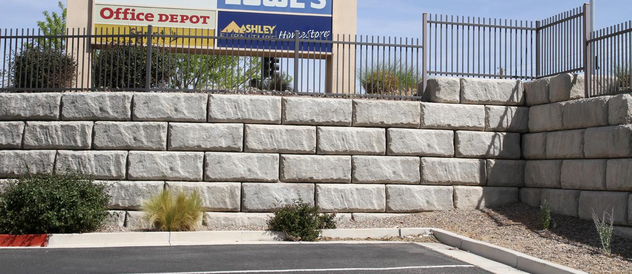
83DETAILING
PRECAST MODULAR BLOCK DESIGN
MANUAL VOLUME 1: GRAVITY WALLS
Fig. 5.1. Example running bond installation.
5.3.
LEVELING PAD
The primary purpose of a leveling pad is to provide a clean, smooth, level, dense surface on which to build the PMB gravity retaining wall. While the leveling pad does provide some benefit in the distribution of pressure from the weight of the wall to the foundation soils, it is not intended to serve as a rigid, structural footing. Designers recognize that walls made from discrete PMB units are somewhat flexible and can therefore tolerate small movements without damage or strength reduction. Consequently, the leveling pad serves as an area on which to begin construction rather than as a traditional structural footing. The two most common types of materials used to construct a leveling pad are granular material (gravel or crushed stone) or lean concrete.
Crushed stone leveling pads are typically between 6 and 12 inches (150 and 300 mm) thick. The pads extend in front of the bottom PMB unit by at least 6 inches (150 mm) and behind the same unit by 6 to 12 inches (150 to 300 mm). If the wall is located in an area where the wall drain can gravity flow to daylight below the elevation of the bottom of the leveling pad, the leveling pad material is usually an open-graded crushed stone. Material meeting the requirements of No. 57 stone (ASTM C33 or AASHTO M43) with no material passing the number 200 (0.075 mm) sieve is preferred. In projects where the wall drain can only outlet to daylight somewhere above the bottom of the leveling pad, a dense-graded crushed stone or graded aggregate base material with between 8 and 20% “fines” which will pass through a No. 200 (0.075 mm) sieve is typically used. The lower permeability of the dense-graded aggregate will tend to force any water in the open-graded stone behind the blocks to flow into the drain rather than into the foundation soils below the wall. An example crushed stone leveling pad is shown in Figure 5.2 and a graded aggregate base leveling pad is shown in Figure 5.3.
DETAILING PRECAST MODULAR BLOCK DESIGN MANUAL VOLUME 1: GRAVITY WALLS 84
Fig. 5.2. Example crushed stone leveling pad. Fig. 5.3. Example graded aggregate base leveling pad.
Lean concrete leveling pads are typically 6 inches (150 mm) thick and extend in front of and behind the bottom PMB unit by 6 inches (150 mm). The concrete generally has a 28-day com pressive strength of 2,500 psi (17.2 MPa) and is not reinforced with steel rebar, fibers, or other types of reinforcement. An example lean concrete leveling pad is shown in Figure 5.4.
Fig. 5.4. Example lean concrete leveling pad.
If a structural footing is required, it should be designed separately following standard practice for reinforced concrete structures. An example of where this might be required is the case of very soft foundation soils where a reinforced concrete footing is designed to act as a pile-sup ported grade beam that in turn supports the wall.
5.4. DRAINS
Best practice in retaining wall design and construction is to provide plenty of drainage near the wall. Water exerts a hydrostatic force on the wall and it can produce buoyant forces in the supported and infill soils, both of which can have destabilizing effects on the wall.
PMB walls include a clean, open-graded stone backfill material around the PMB units. Although the earliest use of stone with segmental retaining wall units was intended as a compaction aid, it quickly was expanded to serve as a drainage medium as well. The stone material is placed in any hollow cores in the PMB units and between adjacent PMB units. For many PMB units, the stone is also placed at least 12 inches (300 mm) behind the PMB units, although this requirement is sometimes waived for very large hollow-core units (such as Redi-Rock XL units) that have a large area of stone between and throughout the units. A material meeting the requirements of No. 57 stone (ASTM C33 or AASHTO M43) with no material passing the number 200 (0.075 mm) sieve is preferred because it drains very quickly and does not allow pore pressures to build up on the wall.
A drain pipe is placed behind the PMB units at the lowest elevation where the pipe can ade quately outlet to daylight. The drain pipe collects any water traveling through the stone backfill material and quickly and safely outlets the water away from the wall. The drain pipe should be at least 4 inches (100 mm) in diameter, perforated, and surrounded by the open-graded stone. Pipes made from PVC or HDPE are common. For some applications, the drain pipe and stone are wrapped with a non-woven geotextile fabric.
The drain pipe runs the entire length of the wall and needs to have proper outlets on the ends and at regularly spaced points along the wall. If the pipe is unable to outlet under the PMB blocks, provisions such for field modifications or weep hole outlets cast into select PMB units (as shown in Figure 5.5) must be made to facilitate drainage through the wall. If a flexible pipe,
85DETAILING PRECAST MODULAR BLOCK DESIGN MANUAL VOLUME 1: GRAVITY WALLS
with or without a geotextile wrap, is used, an adaptor should be used to convert to a solid pipe for weep hole outlets through the face or under the retaining wall. It’s also quite important that care be taken during installation to avoid crushing or damaging the drain pipe or outlets. An example drain is shown in Figure 5.5.
5.5. SLOPES
PMB gravity walls are used to create usable space, either at the top or bottom of the wall. They almost always need to account for slopes in the existing or proposed ground. The slopes can either be parallel to the wall, perpendicular to the wall, or at some skewed angle that incorpo rates sloping ground in both directions. Fortunately, walls can be designed to accommodate all these conditions.
5.5.1. Sloping Grade Parallel to Wall
When the ground elevations rise or fall along the length of the wall, the wall needs to adjust to the grade changes. If the grade changes are at the bottom of the wall, the design can include steps in the bottom of wall elevation. The step changes are made when the bury depth to the bottom of the wall is at least the minimum bury depth plus the height of a PMB unit or greater. The leveling pad is extended past the elevation change by at least 6 inches (150 mm) and then rises up to the new elevation at a slope of 1 horizontal to 1 vertical or flatter. An example step change in the bottom of the wall is shown in Figure 5.6.
DETAILING PRECAST MODULAR BLOCK DESIGN MANUAL VOLUME 1: GRAVITY WALLS 86
Fig.
5.5. Example wall drain outlet.
Fig. 5.6. Example step change in the bottom of a PMB wall.
If the grade changes are at the top of the wall, the design can include steps at the top of wall elevation. PMB units with texture on two or more sides are used to maintain a finished wall appearance as the ground elevation on top of the wall slopes up or down. Example step changes in the top of a wall are shown in Figure 5.7.
Fig. 5.7. Example step changes in the top of a PMB wall.
Most PMB walls are constructed level and accommodate elevation changes along the wall with step changes. However, there may be instances such as along a road, walkway, or trail with smaller grade changes where the designer would rather install the wall parallel to the ground surface, following the vertical alignment of the road or trail, than install it perfectly horizontal. Often this installation is limited to slopes of 5% or less and vertical curves of 1,000 ft (300 m) or greater. The Peaks to Plains Trail through Clear Creek Canyon in Colorado shown in Figure 5.8 includes PMB walls specifically designed to follow grade changes in the trail.
87DETAILING PRECAST MODULAR BLOCK DESIGN MANUAL VOLUME 1: GRAVITY WALLS
When PMB walls are constructed to follow sloping grades, extra care must be taken at the ver tical curve locations where the grade changes. In a vertical curve, adjacent PMB units will touch at either their top or bottom corners (depending on whether the curve is in a sag or a crest) and will have space between the units at the other corner. Walls designed to follow sloping grades should be limited to projects with sufficiently flat vertical curves that prevent the gap at either the top or bottom corner of PMB units from exceeding the maximum allowable joint spacing between units. Also, care should be taken with mechanically stabilized earth walls (which are not included in this volume) to ensure the capacity of the geogrid-PMB unit connection is not reduced by a sloping grade installation.
5.5.2. Sloping Grade Perpendicular to Wall
When the ground elevations rise or fall perpendicular to the wall, the designer must account for the slope in both the stability calculations and in the construction details.
If a crest slope is present on top of the wall, active earth pressure on the wall increases. In ad dition, the designer must consider any surface water that would runoff during a rainfall event and direct the water away from the wall. Lined, vegetated swales are often incorporated above the top of the wall to safely convey this water away and prevent it from spilling over the top of the wall. The designer is encouraged to use sound engineering judgment when addressing this issue. Swales should not be constructed in a manner that impounds water or facilitates infiltration into the ground at the top of the wall. At the same time, uncontrolled water spilling over the face of the wall has led to failures. Unmitigated spillage may stain the wall, or more concerningly, cause erosion at the base of the wall. The specific details of the drainage channel will vary with particular PMB units and project requirements, but a typical example is shown in Figure 5.9.
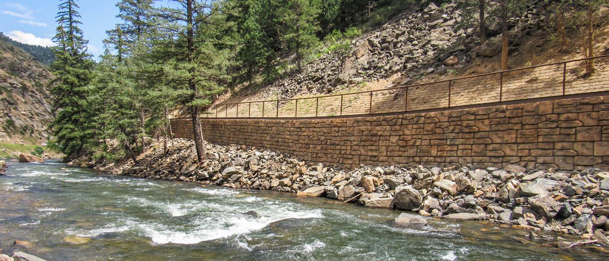
DETAILING PRECAST MODULAR BLOCK DESIGN MANUAL VOLUME 1: GRAVITY WALLS 88
Fig. 5.8. PMB wall constructed with sloping grades, Clear Creek Canyon, Colorado, USA.
Fig. 5.9. Example drainage swales on the top of a wall.
A toe slope on the bottom of the wall reduces the bearing capacity of the foundation soils and increases the minimum required embedment. From a construction perspective, most designs include a bench or horizontal clearance between the toe of the wall and the slope to help increase stability and provide room for construction. A minimum 4 foot (1.2 meter) bench is common. An example is shown in Figure 5.10.
Fig. 5.10. Example bench at toe of wall.
5.6. BARRIERS
An important design consideration for retaining walls is how to ensure the stuff on top of the wall remains on top of the wall. This is accomplished with handrails, fences, and other types of barriers. Because PMB units are quite large, PMB walls are well suited to host such barriers.
89DETAILING PRECAST MODULAR BLOCK DESIGN MANUAL VOLUME 1: GRAVITY WALLS
5.6.1. Rails and Fences
Pedestrian rails are included when a walkway is located at the top of a wall. The top PMB unit may be flush with the grade or extend above the grade and provide a curb. Pedestrian railings are attached to the top PMB units, which must be large enough to resist overturning or toppling forces from the rail. Design loads for pedestrian handrails are provided in Section 3.6.1 and for fences in 3.6.2. An example pedestrian handrail is shown in Figure 5.11 and an example fence is shown in Figure 5.12.
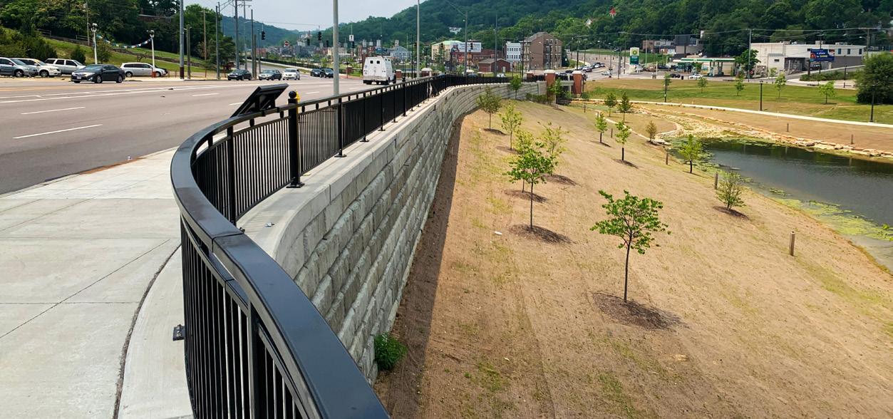
Fig. 5.11. Example pedestrian railing installation.
Fig. 5.12. Example fence installation.
Posts for the rail or fence should be attached to the PMB units or installed adjacent to them so loads can be transferred safely to the wall. If the PMB units are core-drilled to make a hole for post installation, the posts should be located far enough away from the edges of the units to avoid concrete rupture under moment transferred from the posts. Any space around the
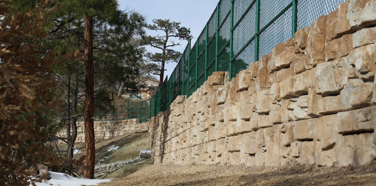
DETAILING PRECAST MODULAR BLOCK DESIGN MANUAL VOLUME 1: GRAVITY WALLS 90
posts should be filled with a non-shrink grout. If a base flange is used to connect the posts to the PMB units, the anchor bolts should be sized appropriately and located in an area where the full concrete strength to resist rupture or pull-out can be generated.
5.6.2. Traffic Barriers
Traffic barriers require multiple design considerations. When used on the top of walls adjacent to roadways, especially at higher speeds, the barrier needs to safely contain and redirect the vehicle away from the edge of the wall in a controlled manner that protects the vehicle’s occu pants from serious injury to the maximum extent possible. The barrier must be strong enough to keep the vehicle from punching through and it should be shaped in a way to redirect the vehicle without it flipping or rebounding in an uncontrolled manner. When used on the top of walls in low-speed applications, such as along city streets, in parking lots, or along driveways, the barrier must safely contain the vehicle; however, the shape and texture requirements of highway barriers are less important.
There are three common traffic barriers used with PMB walls: post-and-beam guardrails, con crete parapet walls (often F-shaped or New Jersey barrier) with a reinforced concrete moment slab, and parapet walls and a moment slab that incorporate PMB units. The engineer responsible for traffic control will determine the particular barrier to use. The wall design engineer needs to understand the design considerations each barrier has on the wall.
5.6.2.1. Post-and-Beam Guardrail
Post-and-beam guardrails are primarily used parallel to traveled roadways to keep vehicles from leaving the road surface. Impacts are often skewed at angles of 45° or less. Post-and-beam guardrails are also used in low speed applications where impacts can be at angles up to 90°.
AASHTO (2020) requires a minimum of 3 feet (0.9 meter) separation between the post and the wall face. Although the authors could not find a source specifically documenting reasons for this requirement, conversations with many design engineers and Federal Highway Admin istration staff indicate that the minimum 3 feet distance is at least partly intended to give the guardrail space to deform and redirect the vehicle back to the traveled roadway without the vehicle toppling over the edge of the wall. PMB units can be quite large and, in some cases, offer hollow core centers that allow for easy installation of guardrail posts. The designer should carefully consider the intended application when selecting placement location for a post-andbeam guardrail in or next to a PMB wall.
An example post-and-beam guardrail installation is shown in Figure 5.13.
91DETAILING PRECAST MODULAR BLOCK DESIGN MANUAL VOLUME 1: GRAVITY WALLS
Fig. 5.13. Example post-and-beam guardrail installation.
5.6.2.2. Concrete Parapet Wall with Moment Slab
Concrete parapet walls and moment slabs can be incorporated into projects through their placement on top of PMB gravity walls.
Concrete barriers for use in highway and other transportation projects often have a specific shape, such as the FHWA “F” shape or a New Jersey barrier shape. These shapes have been fully tested to evaluate the performance of vehicles during an impact. Many Department of Transportation agencies will have construction details for the barriers they require on their projects. Highway barriers are most often cast-in-place on top of the wall, however, some projects might use precast barriers.
For walls featuring elevation changes in the top of the wall due to sloping grades, a cast-inplace concrete “level-up” strip is constructed to provide a smooth, uniform surface for the barrier. In these cases, the barrier includes an extra coping feature on the outside face to hide the level-up strip and provide a finished appearance to the top of the wall.
Since moment slabs are sized to resist a fairly significant static load (see Sections 3.6.4 and 3.6.5), they tend to be large and are always cast-in-place. Common moment slabs are often 5 to 8 feet (1.5 to 2.4 m) wide (perpendicular to the wall face), 20 to 30 feet (6.1 to 9.1 m) long (parallel to the wall face), and 8 to 12 inches (200 to 300 mm) thick. Moment slabs include steel rebar to resist the bending, shear, and rupture forces in the concrete, and they include features like dowels to connect adjacent slab sections to each other.
An example concrete parapet wall and moment slab installation is shown in Figure 5.14.
DETAILING PRECAST MODULAR BLOCK DESIGN MANUAL VOLUME 1: GRAVITY WALLS 92
Fig. 5.14. Example concrete parapet wall with moment slab.
5.6.2.3. Parapet Walls and Moment Slab that Incorporate PMB Units
When used on the top of walls in low speed applications, the shape requirements (“F” shape or New Jersey barrier) of classic highway style barriers are not needed. In these applications, the size and aesthetic quality of PMB units can be used to create safe, attractive barriers.
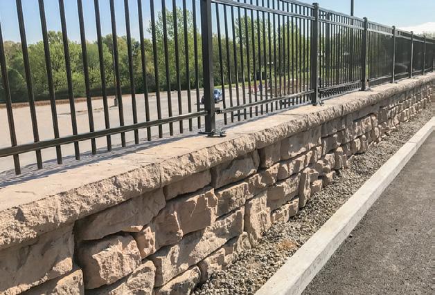
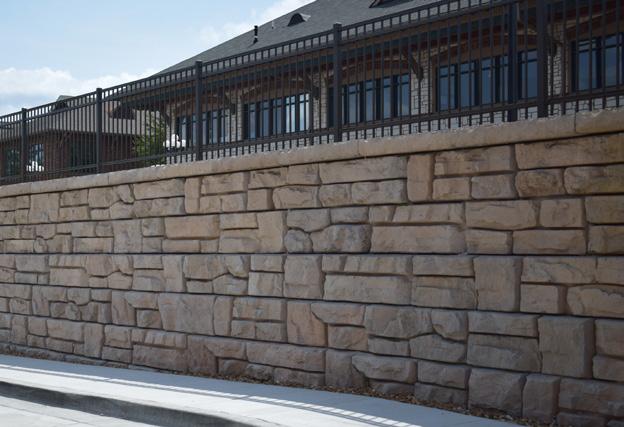
An installation from St. Peters, Missouri, USA, is shown in Figure 5.15. This project utilized a parapet wall constructed from hollow core freestanding PMB units connected to each other and attached to the PMB retaining units below with steel rebar and cast-in-place concrete. This con figuration provided a barrier separating an upper level parking area from a gas station below.
Fig. 5.15. Parapet wall incorporating PMB units from St. Peters, Missouri, USA.
An example of details required to construct a parapet wall and moment slab incorporating PMB units is shown in Figure 5.16.
93DETAILING PRECAST MODULAR BLOCK DESIGN MANUAL VOLUME 1: GRAVITY WALLS
5.7. CURVES AND CORNERS
Few walls are straight. Most feature curves and corners, resulting in attractive walls that meet project requirements. Consequently, most PMB units include design features that facilitate construction of curves and corners.
5.7.1. Curves
Often PMB units have tapered sides to allow for easy construction of curves. When constructing convex curves, the taper on the PMB units will set how closely the units can be placed together and define the minimum radius needed to accommodate adjacent units. The block-to-block setback of the units must also be considered in the wall layout. Much like the inside lanes of a race track, the block-to-block setback will cause the radius for each succeeding row of PMB units to be shorter than the row below. Designers must select a sufficiently long radius for the base of the wall so that blocks can still fit together upon reaching the top of the wall. Licensing companies like Aster Brands often have design aids that help select minimum radii for different combinations of wall heights and block-to-block setbacks. A convex curve is shown in Figure 5.17.
DETAILING PRECAST MODULAR BLOCK DESIGN MANUAL VOLUME 1: GRAVITY WALLS 94
Fig. 5.16. Example parapet wall and moment slab incorporating PMB units.
Fig. 5.17. Convex curves for PMB walls.
Concave curves constructed with PMB units are not physically limited to a fixed minimum radius as adjacent units only touch at one point near the face of the units. Instead, the concern for wall designers is aesthetic. PMB units are a fixed size and produce faceted curves. If the radius of the curve is too short, the wall will look overly faceted and portions of units that do not feature finished textured surfaces can become visible. Recommended minimum radius requirements for a concave curve are often provided to prevent design and construction of walls that are less visually appealing. A concave curve is shown in Figure 5.18.
Fig. 5.18. Concave curves for PMB walls.
Wall designers and installation contractors should also be aware that curves will impact the running bond installation pattern. PMB units will drift in and out of running bond alignment for walls constructed with concave and convex curves. This becomes a concern when walls need to turn a corner or meet a fixed position such as the wall of a building. Strategies have been developed to help in these conditions. First, wall installations are best started at the fixed point (corner or end of wall). As construction proceeds away from the fixed point, the impact of blocks drifting from a perfect running bond becomes less. Second, there are often smaller sized (shorter) PMB units that can be used to help the installation pattern return to a running bond pattern. Finally, installers may need to cut PMB units to make them fit the required alignment. Proper planning and utilization of the first two strategies can help limit the amount of field cutting required to deliver an attractive patterned wall that fits into the required geometry.
95DETAILING PRECAST MODULAR BLOCK DESIGN MANUAL VOLUME 1: GRAVITY WALLS
5.7.2. Corners
Corners can be easily constructed in PMB walls; however, advance planning is required to pro duce sharp, functional corners. Construction of outside and inside corners demand specific units for each. Additional considerations must be made for walls with double corner locations.
Outside corners typically require special PMB units offering finish texture on two or more sides and features allowing integration with standard retaining units. Construction details should be based on project specific details taking into account considerations like the wall batter in both directions. Depending on the particular details, field modifications of the PMB units such as trimming alignment knobs might be required. Generally these modifications can be made without impacting the structural integrity of the corner. PMB manufacturers or licensors are excellent sources of information when selecting proper units and entertaining any required field modifications for corners. They often can provide construction details for most common applications. An example outside corner is shown in Figure 5.19.
Fig. 5.19. Outside corner construction.
Inside corners can often be constructed without the need for special PMB corner units. To construct an inside corner, one wall is extended past the corner location and the other wall is built flush with the first wall. In some applications the walls will simply abut each other. In other applications careful planning and unit placement will allow the corner to be constructed with interlocking units. An example inside corner (with interlocking units) is shown in Figure 5.20.
Fig. 5.20. Inside corner construction.
The three dimensional considerations due to the batter in each wall segment make planning even more important for walls that require a double corner installation. For walls with double outside corners, the middle wall segment between corner locations gets shorter with each successive row due to the wall batter. Some manufacturers offer “short” units that are sized to subtract the standard wall batter from each side wall from the standard unit length. Use of these short units allows for construction of the middle wall segment without field cutting
DETAILING PRECAST MODULAR BLOCK DESIGN MANUAL VOLUME 1: GRAVITY WALLS 96
any units. An example is shown in Figure 5.21. For applications with curves or changes in wall batter, the installer will need to field cut one PMB unit per row to construct the double corner.
Fig. 5.21. Double outside corner construction.
Double inside corners offer simpler construction. The only change from the construction prac tice of a single inside corner is that the blocks may only be interlocked for one corner, not both. An example double inside corner is shown in Figure 5.22.
Fig. 5.22. Double inside corner construction.
5.8. UTILITIES AND CULVERTS
Retaining walls are considered civil structures and they often need to be designed and con structed in a manner that allows them to accommodate utility lines in close proximity. Joint planning with the wall designer and project civil engineer that considers the effects of the wall and utilities on each other can often limit conflicts, reduce cost, and simplify construction. This section describes some of the most common items of concern when utilities and walls cannot be separated and need to be constructed together.
5.8.1. Dry Utilities
One of the biggest issues with dry utility lines such as power lines, cable, telecommunication lines, or fiber optic lines is proximity of the utility to the wall. There must be enough room between the wall and the utility to allow for construction. It is especially critical to provide suf ficient space to achieve full compaction of the retained soil behind the wall units. As the utility line gets closer to the wall, special compaction techniques must be used. Another concern is the impact of wall movement on the utility line. PMB retaining walls are most often designed using active earth pressure, which requires a small amount of movement (rotation and transla
97DETAILING PRECAST MODULAR BLOCK DESIGN MANUAL VOLUME 1: GRAVITY WALLS
tion) to mobilize. Utilities that are sensitive to small amounts of movement should be located a sufficient distance from the wall so as not to be impacted by movement as soil pressures are being mobilized. In the event no movement can be tolerated and the utility and wall cannot be separated, the utility must be included in a larger conduit or pipe or the wall must be designed to support at-rest earth pressure.
5.8.2. Wet Utilities
Wet utilities such as water main, sanitary sewers, or storm sewers demand the same consider ations as dry utilities (room for construction and tolerance to small movements), however they include the additional consideration that the utility might rupture and leak. Design features to address this concern include use of thrust blocks for bends and ends in the utility lines and extra drainage features surrounding the utility line. Depending on the proximity of the utility lines to the wall, additional forces from the thrust block might need to be included in the wall stability analysis. An example thrust block is shown in Figure 5.23 and drainage feature is shown in Figure 5.24.
DETAILING PRECAST MODULAR BLOCK DESIGN MANUAL VOLUME 1: GRAVITY WALLS 98
Fig.
5.23. Example thrust block usage for wet utility.
5.8.3. Pipes Installed Through the Wall
In some cases, a pipe or utility such as a storm sewer will actually need to penetrate through the face of the wall. This is easily accomplished in a PMB wall by simply eliminating one or more PMB units and constructing a concrete collar around the pipe. Specifics of the collar will vary. For small pipes in short walls, the collar may be simply cast-in-place concrete between adjacent PMB units and the pipe. Larger pipes and/or taller walls might require a detailed struc tural design of a reinforced concrete collar. The designer should consider the angle of the pipe passing through the wall when deciding how many units need to be replaced with the collar and pipe. An example of a pipe installed perpendicular to the wall is shown in Figure 5.25 and an example of a pipe installed at an angle to the wall is shown in Figure 5.26.

99DETAILING PRECAST MODULAR BLOCK DESIGN MANUAL VOLUME 1: GRAVITY WALLS
Fig. 5.24. Example drainage feature for wet utility.
Fig. 5.25. Pipe installed perpendicular to a wall.
Fig. 5.26. Pipe installed at an angle to a wall.
Often pipes that pass through a wall are culverts or drains. It is absolutely critical in these ap plications that the designer consider the full amount of scour anticipated from the drain and that measures to protect the wall such as stone armor or riprap are included. The utility design might also include details such as manhole drop inlets to help reduce the impact of water that needs to outlet lower near the base of a wall. The wall designer should review the impacts of the wall and utility lines on each other with the project’s civil engineer.
5.8.4. Culvert Headwalls

PMB walls are often used as headwall structures for culverts. Box culverts are easily accommo dated by simply planning a horizontal row at the elevation of the top of the box as shown in Figure 5.27.
Fig. 5.27. PMB headwall constructed around a box culvert.
Elliptical or arched culvert installations may also be performed. In this case, the PMB wall is
DETAILING PRECAST MODULAR BLOCK DESIGN MANUAL VOLUME 1: GRAVITY WALLS 100
constructed as close to the culvert as the units will allow. The remaining gaps between PMB units and the culvert can be filled by either trimming units (if the gaps are small) or using cast-in-place concrete. Figures 5.28 and 5.29 show an application where custom concrete face panels cast to match the PMB units were cut to fit the arch culvert.
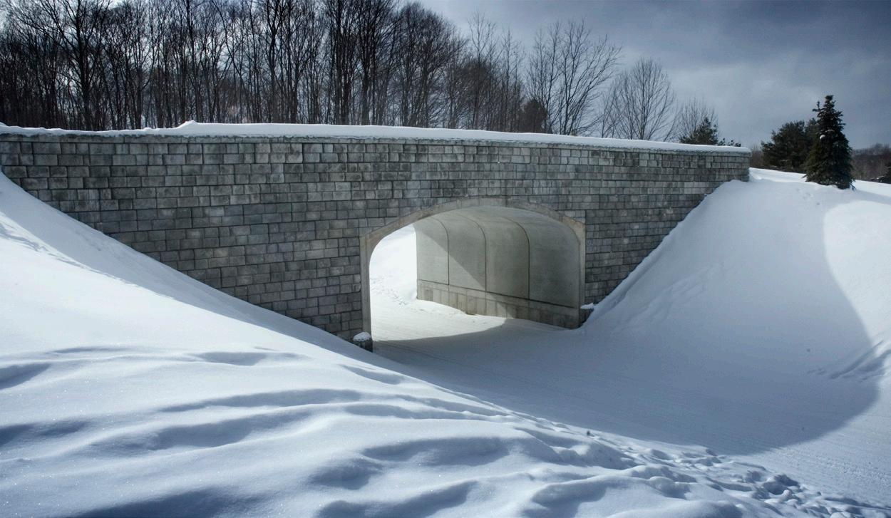
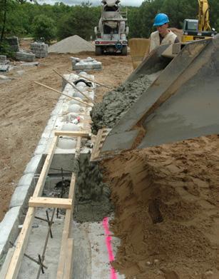
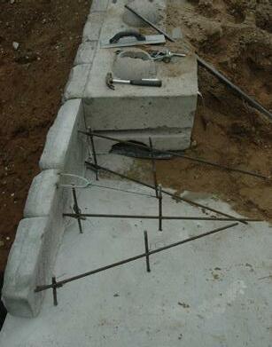
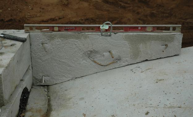
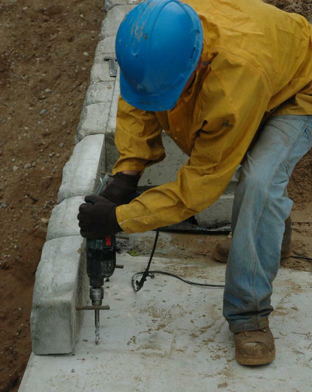
101DETAILING
PRECAST MODULAR BLOCK DESIGN MANUAL VOLUME 1: GRAVITY WALLS
Fig. 5.28. PMB headwall construction around an arched culvert.
Fig. 5.29. Completed PMB headwall around an arched culvert.
5.8.5.
Vertical Slip Joint
On occasion, walls are constructed around structural footings or with large collars for utility penetrations where the wall might experience varied long term settlement conditions in differ ent locations. In these cases, the wall designer needs to include some type of vertical control joint or “slip joint”. Vertical control joints are easily constructed in PMB walls using full length and half length units. An example installation is shown in Figure 5.30.

5.9. CONSTRUCTION TOLERANCES
PMB walls are constructed with discrete units that are stacked together without the use of mortar or other type of adhesive. As a result, PMB walls are somewhat flexible and can tolerate small movements without damage or strength reduction. With too much movement the walls will become unsightly, often long before there are any stability concerns, and wall designers will want to limit the amount of movement during or after construction. PMB walls follow the same general construction tolerance limits as other types of block or MSE walls.
5.9.1. Wall Tolerances
Maximum movement due to both construction tolerances and post construction settlement and movement is generally limited between ½% and 1% horizontally and vertically. This equates to approximately 1” to 2” in 20’ (3 cm to 6 cm in 6 m).
Rotation of the wall is generally required to be between 1° and 2° from plan batter.
5.9.2. PMB Unit Tolerances
ASTM C1776 has recommended tolerances for PMB units. According to C1776, overall dimen sions for height should be no more than ³⁄₁₆" (5 mm) and length should be no more than ½” (13 mm) from the specified standard dimensions. The overall dimension for width should be no more than ½” (13 mm) less than the specified standard width; however, dimensional tolerance requirements for width are waived for architectural surfaces. Finally, the diagonal dimensions of
DETAILING PRECAST MODULAR BLOCK DESIGN MANUAL VOLUME 1: GRAVITY WALLS 102
Fig. 5.30. Example vertical control joint.
5.10.
the exposed face should vary by no more than ½” (13 mm), exclusive of the architectural face texture. Most PMB manufacturers publish requirements for their specific units. In some cases, these requirements are even more stringent than the ASTM specification.
Wall designers are asked frequently about accommodations for adjacent units that have slightly different unit heights but are still within allowable dimensional tolerance limits. Many installers propose the usage of shims to adjust for the different unit heights. Shims can be successfully utilized as long as they do not interfere with the interlocking features of the PMB units, reduce friction between units, and lower the block-to-block interface shear capacity. If allowed, shims should cover a large portion of the bearing surface on the top of the shorter unit. Common asphalt roofing shingles or rolled asphalt roofing, cut to fit, is often preferred over small plastic tapered shims or coins because they allow even distribution of pressure over the entire PMB unit and limit point loads from small shims.
MAXIMUM JOINT WIDTH
PMB units are intended to be placed with their sides tight to the adjacent units. There are some acceptable instances when small spaces between units have been required to account for block tolerances and construction placement. Wall designers will often follow the approach provided in FHWA-NHI-10-024 (2009) to size maximum slot widths in drainage pipes to estab lish maximum allowable joint widths between adjacent PMB units. Per equation 5.8 in FHWANHI-10-024, the maximum slot width should be less than D85 (the particle size diameter which 85% of the soil particles on a cumulative particle-size distribution curve will pass) divided by 1.2 to 1.4.
As an example, the particle size distribution curve and D85 for number 57 stone (ASTM C33 or AASHTO M43) is shown in Figure 5.31. The maximum joint width between PMB units that utilize number 57 stone backfill material calculated with the FHWA equation would be 0.4” to 0.5” (11 mm to 13 mm).
Fig. 5.31. Particle-size distribution curve for No. 57 stone.
Another common detail in PMB wall construction is to provide a non-woven geotextile fabric
103DETAILING PRECAST MODULAR BLOCK DESIGN MANUAL VOLUME 1: GRAVITY WALLS
to cover the joints between adjacent PMB units to help limit migration of granular material, particularly the finer grained particles, through the joints between units at the face of the wall. An example installation is shown in Figure 5.32.
Fig. 5.32. Example non-woven geotextile fabric installation between adjacent PMB units.
DETAILING PRECAST MODULAR BLOCK DESIGN MANUAL VOLUME 1: GRAVITY WALLS 104
CHAPTER 6.0
BEST PRACTICES
6.1.
GEOTECHNICAL SITE INVESTIGATION
The effective design of precast modular block retaining walls truly begins with an accurate understanding of the subsurface conditions. All retaining walls are geotechnical structures, but none are so dependent upon the geotechnical conditions in which they are situated as a precast modular block retaining wall. A geotechnical subsurface investigation report is essential not only to provide for sufficient design input parameters but to allow for design optimization and the minimization of unnecessary material costs.
The geotechnical subsurface investigation report should be site-specific and include test bor ings within reasonable proximity to the retaining wall location. Most often these borings are spaced along the retaining wall alignment. However, sometimes additional borings may be needed at the top and/or bottom of a sloping crest or sloping toe to help define those layers of soil strata or rock that may influence the global (overall) stability of the retaining wall and the stability of the graded earth slope within which it will be constructed.
Test borings in a typical subsurface study for a retaining wall should include the following:
• A minimum of two (2) borings should be provided per wall regardless of length.
• Maximum spacing of the borings should not exceed 75 feet on-center along the alignment of the retaining wall.
• The borings should be advanced to a depth of 1.5 times the wall height below the bottom of the proposed retaining wall leveling pad or to refusal in competent rock.
• Where competent rock is encountered, a rock core of an additional 10 feet should be completed to verify the continuity of the rock and determine the rock quality designation (RQD) of the rock sampled. Typical frequency of the rock cores should be a minimum of one per wall and least one per four boring locations per wall.
• The boring logs should include SPT or DCPT data, groundwater depth observations, soil moisture content and Atterberg Limits of the fine-grained soils.
• The boring logs should include northing and easting coordinates for the boring location and MSL elevation for the existing ground surface at the drilling location.
Sometimes site access, existing vegetation or topography can make location of the borings difficult or impossible before the retaining wall design must begin. In these situations, it may be appropriate to prepare preliminary retaining wall construction drawings marked “not for construction” that can be finalized after site grading has progressed to a point that the retain ing wall construction area(s) are accessible by drilling equipment. It’s important to understand that significant changes in the retaining wall design may be necessary once the subsurface conditions are finalized. Adequate contingency should be incorporated in the cost estimate to account for this uncertainty when soil borings are not obtained prior to preliminary design.
105BEST PRACTICES PRECAST MODULAR BLOCK DESIGN MANUAL VOLUME 1: GRAVITY WALLS
Note: Final sealed construction drawings for a retaining wall should never be issued without site-specific subsurface geotechnical information that the retaining wall designer feels has been properly prepared by a qualified geotechnical engineering firm, is adequate in its scope of study, and is representative for the proposed retaining wall structure.
6.2. DESIGN PARAMETERS
Characterization of the physical properties of the soil conditions is another critical component of the geotechnical subsurface investigation. The following information should be included in the geotechnical investigation report.
• Particle size distribution in accordance with ASTM D6913 and clay size fraction in accordance with ASTM D7928 for the representative native soils encountered should be provided.
• Effective stress shear strength (drained) recommendations for the native soils should be also provided. This data typically models the long-term design condition and includes recommendations for internal friction angle, effective cohesion, and total unit weight. Laboratory tests to determine these values are specific to the soils encountered in the subsurface investigation and should be selected with input from the geotechnical testing firm. In some cases, the site soils may exhibit very low total stress (undrained) shear strength. When these soils are encountered, the short-term, undrained stability should also be evaluated and appropriate total stress shear strength parameters should also be included.
• The geotechnical report should include allowable bearing capacity recommendations for shallow continuous footings that are appropriate for precast modular block walls founded on concrete or crushed stone leveling pads. Allowable bearing capacity recommendations for walls founded on controlled fills, native (undisturbed) soils, and bedrock should also be provided.
• Seismic design parameters based upon the project location and subsurface conditions.
• Finally, the geotechnical report should identify and discuss any irregularities known to exist in the soils and rock encountered whether they have been specifically observed or not. Karst geology (rock formations given to sinkhole formation), pyritic shales or other sedimentary rock formations that may quickly swell or degrade when exposed should be noted. Expansive clay, loessial sands and silts, slickensided clays, lacustrine lakebed clays, etc. that should be addressed specifically in stability modeling or drainage design should also be identified and discussed in the geotechnical report.
6.3. SITE GRADING, ALIGNMENT, AND UTILITIES
Site grading to reduce the height, length, and face area of a retaining wall is common practice to reduce the overall cost of the project. Sometimes, fairly extreme slope conditions of 2H:1V or steeper are considered. If retaining walls are to be designed in conjunction with an earth slope, typically the lowest cost option is to place the retaining wall at the bottom with the earth slope above. Of course, this is not always feasible given the grading limits of a particular site. When possible, use the following guidelines for grading above and below a precast concrete retaining wall.
BEST PRACTICES PRECAST MODULAR BLOCK DESIGN MANUAL VOLUME 1: GRAVITY WALLS 106
• Place the retaining wall at the bottom and the slope above. If grading below, or above and below, the retaining wall is necessary, limit slopes to 3H:1V or flatter.
• Provide surface drainage away from the retaining wall crest. Avoid surface drainage from a crest slope that will overtop the retaining wall. Provide a drainage swale at the wall crest that is sufficiently sized to translate the anticipated runoff to the ends of the retaining wall or into the storm sewer system.
• Sod swales are preferable to concrete. Improperly sized concrete swales can increase flow velocity and overflow causing erosion along the sides of the swale. This erosion can lead to the removal of critical cap soil at the top of the wall that is designed to protect the structural granular backfill behind the retaining wall.
• If the crest slope above the wall is to be vegetated, place temporary silt fence behind the wall crest immediately following wall construction when the crest slope is 8H:1V or steeper. This will protect the wall face from becoming soil stained from mud overtopping the wall before vegetation can be established.
Proper alignment of the retaining wall should consider the size of the precast modular block units to be utilized. Plan views of the retaining wall should be prepared that show the width of the block units at scale in relation to everything else around it. Most precast modular block units can be cast with certain interlocking features or components that allow the facing batter, horizontal set-back, to be adjusted to achieve greater height as a gravity structure without ex ternal tie backs, geogrid or other horizontal structural supports. It is important to take the face batter into consideration when planning the wall location to avoid conflict with other structures and utilities. Consider the following when determining the final wall location and length:
• Prepare a plan view of the retaining wall layout at scale to determine potential conflicts with utilities and other structures.
• The size of the precast modular block units is an important consideration in the wall length. Because most PMB units weigh in excess of 1,500 lbs., cutting the blocks in the field is usually an expensive and time-consuming ordeal. The final wall length should be a multiple of the individual block length.
• Termination points adjacent to other structures, inside and outside 90-degree corners, facing batter set-back, radius segments and minimum/maximum curvature requirements of the PMB units all contribute to the final laying length of the retaining wall alignment.
Precast modular block retaining wall systems, especially when designed as gravity or hybrid structures (reinforced wall with unreinforced gravity top courses), can offer more options for accommodating utilities than other traditional mechanically stabilized earth (MSE) retaining wall systems. Here are a few things to consider when utilities must be placed in close proximity to the retaining wall location.
• For reinforced (MSE) walls, consider designing the wall such that upper courses (6 to 9 feet) do not require reinforcement. This will allow placement of buried utilities immediately behind the retaining wall units that will not require deconstruction of the retaining wall to repair or maintain the utility pipeline or conduit.
• Crushed stone, free-draining backfill should be considered for the structural fill behind the retaining wall when liquid carrying utilities are to be placed in this space.
• Cast-in-place concrete headwalls and pipe collars should be designed for throughwall storm pipe penetrations. Precast modular blocks are difficult to cut in the field and reliance upon the contractor to make acceptable modifications to the blocks
107BEST PRACTICES PRECAST MODULAR BLOCK DESIGN MANUAL VOLUME 1: GRAVITY WALLS
once they are delivered to the work site is not recommended.
The retaining wall designer should work closely with the project civil engineer to determine the best ways to accommodate utilities and adjacent structures in the retaining wall design. Too often the retaining wall design occurs once the project site plan is complete and the project has been released for bidding. In these cases, it becomes necessary for the retaining wall designer to “figure it out” and provide the optimum wall design possible given the situation. When the retaining walls are planned as part of the overall site development design, the following rules of thumb will help to eliminate unnecessary cost:
• For cut walls that will ultimately support the property line or right-of-way with an adjacent property, the retaining wall face should be located a horizontal distance of at least 2 times the maximum wall height from the property limit.
• Driveways, roadways and parking areas supported by the retaining wall should be offset from the top finished face of wall at least seven (7) feet if conventional W-beam guardrail is to be used as a traffic barrier (curb/edge of road to face of wall).
• Alternatively, many precast modular block walls can be designed with above grade wall sections that perform very well as traffic barriers, especially in low vehicle speed applications. An above grade traffic barrier should be considered when the face of the wall supporting the driving or parking surface is located within 5 feet of the edge of pavement or curb. The wall designer should evaluate when and if these structures are required and choose the correct detail for the specific site grading and anticipated vehicle speed.
• Ornamental fencing and handrails can be mounted to precast modular block walls fairly easily by a variety of methods. However, privacy fencing and noise walls that can be wind loaded should be carefully evaluated. Typically, wind-loaded structures should be placed on an independent footing behind the retaining wall units to achieve the lowest overall construction cost.
• Utility poles supporting overhead power lines should be located at a minimum horizontal distance (d) equal to the exposed height (H) of the wall (d > H) behind precast modular block wall units.
6.4. COST ESTIMATING
Retaining walls are expensive. Certainly one of the most critical considerations in the design of any retaining wall is its construction cost. No manual dedicated to best practice in retaining wall design would be complete without attempting to offer some guidance on this important subject. But, where should we begin?
Let’s start by considering the process by and through which retaining wall systems are selected and purchased. For commercial and civil infrastructure projects, this is typically accomplished through competitive bidding. A proprietary retaining wall system or systems are specified by the civil engineer, architect or owner and contractors must respond with a price that includes the design and construction of the retaining wall for the specific project application. This process is referred to as “design-build”.
Accurate cost estimation is only possible with an accurate list of material quantities which requires site specific geo-structural design of the retaining wall. But this is rarely the starting point. During the project design phase, the process of cost estimating usually progresses as the civil site design develops. Initially, this progression must begin without a complete retaining
BEST PRACTICES PRECAST MODULAR BLOCK DESIGN MANUAL VOLUME 1: GRAVITY WALLS 108
wall design. This is often due to evolving grading plans that are influenced by site topography cut and fill, elevation of access points to the site as well as the location of bedrock, needed utilities, easements and the property limits. And these are just a few of the concerns that directly impact the retaining wall scope. Our discussion of cost estimating will focus on the civil design development process and how informed cost decisions, consistent with best practice, should be made to arrive at the final retaining wall construction budget.
1. Rough Scope – This is the initial step that usually involves only the preparation of the wall elevation profile to determine the likely face area and maximum height of the retaining wall to be constructed. Consideration is given to whether the retaining wall will support a cut or a fill excavation, but subsurface geotechnical data is usually not considered at this point. The cost estimate that follows the “rough scope” exercise is often based upon a historical unit price per square foot of retaining walls of similar scope.
2. Feasibility Evaluation – The next step in the process is a feasibility evaluation that will help determine if the preferred retaining wall system can be designed and cost-effectively constructed for the given application on the specific site. This step involves an engineering assessment of the subsurface geotechnical conditions as well as the loading conditions that the retaining wall is expected to support. At this point, a determination as to the suitability of either gravity design or mechanically stabilized earth design is made. Subsequently, a more refined estimate of the retaining wall cost, based upon historical construction cost data, can be developed. Finally, specifications for the proprietary wall systems are prepared, the scope of the proposed retaining wall is set, and the project is usually advertised for bid.
3. Preliminary Design Estimate – Once the project is out for bid, the contractors will either develop their own preliminary design or look to the precast block suppliers to provide it. While it is preferred to have the retaining wall design engineer involved in every step of the cost estimating process, it is usually at this point when a retaining wall design engineer is engaged. It then becomes the retaining wall design engineer’s responsibility to prepare a preliminary design that includes an accurate summary of material quantities for bidding purposes. The result is a refined cost estimate that the contractor and owner can reasonably rely upon for contract budget purposes.
4. Final Design Cost – Once the contract is awarded, the final design phase of the retaining wall is typically initiated. This is the point in the process when the final construction drawings and supporting structural calculations are prepared in accordance with the retaining wall specifications and geotechnical engineer’s recommendations. A summary of the final material quantities to be permanently incorporated in the retaining wall construction should accompany the final retaining wall design drawings. Provided the previous steps in the cost estimating process have been properly executed and the grading plan and/or the retaining wall scope has not changed during the bidding phase, the final design cost should very closely reflect the preliminary design estimate. It may seem obvious, but the most effective method of maintaining consistency in the material quantities and overall cost of the retaining wall from the preliminary design estimate to the final design cost is to engage the same retaining wall design engineer or engineering firm throughout the process.
6.5. SELECTING A RETAINING WALL DESIGN ENGINEER
The purpose of this manual is to provide a broad basis of understanding for an engineer to
109BEST PRACTICES PRECAST MODULAR BLOCK DESIGN MANUAL VOLUME 1: GRAVITY WALLS
tackle the design of a precast modular block retaining wall. However, sometimes it may be advantageous to outsource the design of the retaining wall to another firm. So, is there a best practice for the selection of a qualified retaining wall design engineer?
All engineering consulting firms have areas of specialty in which they have a great deal of experience. Choosing a firm that lists retaining wall design among their specialized areas of practice and has demonstrated experience in this area is an important first step.
Because retaining walls and more specifically, precast modular block retaining walls, are largely geotechnical structures, the retaining wall design firm should possess a strong background in geotechnical engineering and design. This will permit the best-practice requirement that all the necessary engineering analyses including overall (global) stability analysis of the retaining wall be completed by the same firm.
Other design manuals and industry practice references sometimes recommend that the owner’s geotechnical engineer be made responsible for the overall stability analysis of the retaining wall and that the retaining wall design engineer be responsible only for the internal and local stability of the structure. While this may fit more neatly into the classical roles and responsibilities of the various members of a hypothetical project design team, it does not reflect best practice. Apart from state department of transportation projects wherein the state geotechnical engineer’s office often conducts such evaluations, private development projects take on a serious risk of cost overrun, poor performance, or even structural failure if sealed retaining wall construction drawings are submitted without having addressed global stability.
What kind of insurance should a retaining wall design firm have? Like all businesses, engineering consulting firms carry various forms of commercial and general liability insurance. In addition to this coverage, engineering firms should also maintain professional liability insurance that provides coverage against errors and omissions in design that may lead to additional cost exposure for their client and/or the project owner. Most firms will provide a certificate of all their insurance limits on request as well as any limits of liability for the specific project that are based upon multiples of the firm’s proposed design fee.
So, if a retaining wall design firm is selected to perform the design, who should hire them? Should it be the owner, the owner’s civil consulting firm, the general contractor, or the retaining wall installation subcontractor? This is a question with multiple answers. The shortest answer is that it usually results from the chosen delivery method for the retaining wall construction.
The most common method of delivery for all types of modular block retaining walls is de sign-build. The retaining wall design engineer is most often engaged by the retaining wall installation contractor as part of their design-build team or by the precast modular block producer as part of their material supply contract. While this is the most common method of engagement, it can be argued that this is not always best practice. Design-build necessarily limits the involvement of the retaining wall engineer to the end of the project design sequence. This may be satisfactory for the design of fairly normal retaining wall applications and may even unlock lower construction costs, but it can sometimes be problematic for more complex project applications. So, what is a “critical” or “complex” retaining wall application? The critical nature of a retaining wall application is somewhat subjective. It is identified by how the retaining wall is perceived by the owner and/or the project design team. A retaining wall may be considered a critical structure if it is exceptionally tall or if it has a complex alignment or geometry such as multiple tiers. The wall may be considered critical if it supports another structure, if it is to be constructed in soft or marginal soil conditions or if it is needed to provide the only access point to the project site. The retaining wall may also be considered a critical structure if it simply
BEST PRACTICES PRECAST MODULAR BLOCK DESIGN MANUAL VOLUME 1: GRAVITY WALLS 110
represents a significant portion of the overall construction budget. In these cases, it may be preferable to the owner for the retaining wall engineer to be engaged directly by the owner or as a sub-consultant to the owner’s civil consultant. This arrangement allows better commu nication with the project design team as the site design develops and it delivers a complete retaining wall design as part of the initial project bid documents.
6.6. ENGINEERING DESIGN
The deliverables that comprise the retaining wall design sometimes vary based on the needs of the project, but they should generally include the following:
• Sealed construction drawings
• Sealed design calculations report in support of the construction drawings
• Material quantities summary that lists the all the materials that will be permanently included in the retaining wall construction
The sealed construction drawings should include a plan view, elevation profile view, and critical cross-sections for each retaining wall on the project, as well as necessary construction details that are common for proper installation of the retaining wall system specified. The construction drawings should also include construction specifications that provide written specifications for the retaining wall materials, installation, and inspection requirements.
The sealed design calculations report should begin with a summary that states the input pa rameters necessary for the retaining wall design and references the sources of that information. Specific loading conditions, sloping crest and sloping toe conditions, and drainage consider ations that were evaluated in the design process should also be included. Output from the design software utilized for stability analysis should be attached for each critical retaining wall section evaluated.
The purpose of the material quantities summary is to promote consistent pricing by the con tractors involved and to minimize the opportunities for misunderstanding that can lead to pricing errors. If included with the design, the material quantities summary should include the quantities of each type of the block units required as well as geosynthetic reinforcement (if needed), geotextile fabric and collection drainpipe quantities, etc. to be incorporated in the final construction. In addition to these materials, it may be advantageous to the client to provide neat quantities of leveling pad, drainage fill, and structural backfill materials. It may also be reasonable to add an engineer’s estimate for rock excavation quantities or volumes of required undercut and replacement of soft foundation soil if required by the project.
Sometimes the design of other structures such as temporary shoring, sheet piles, soil anchors, drilled pier foundations, etc. become necessary related design features of a precast modular block retaining wall design. These items are outside the scope of a typical retaining wall design and are usually provided as a design-build solution by specialty geotechnical contractors. When these items become necessary to the project, the retaining wall design engineer should identify the need for the additional items during preliminary design and then work closely with the de signers of the related structures to understand the interaction and influence of those structures on the precast modular block wall for both short-term and long-term design considerations. The retaining wall construction drawings should always define OSHA safe excavation limits and/or shoring requirements for precast modular block walls that will support cut excavations near property lines, existing structures, or utilities.
111BEST PRACTICES PRECAST MODULAR BLOCK DESIGN MANUAL VOLUME 1: GRAVITY WALLS
CONSTRUCTION
Once the retaining wall construction drawings are approved, the retaining wall design engineer should schedule a preconstruction conference with the contractor(s) involved to review the construction plans and inspection requirements. This conference can be as formal or informal as the participants choose, but it is an important meeting for the construction team to make sure the roles and responsibilities are clearly understood. This conference also allows for questions and answers to project-specific issues.
Following the preconstruction meeting, the retaining wall design engineer should expect to review and approve material submittals and remain on-call to the project construction team to address questions and concerns as construction progresses. Most of the input parameters necessary to retaining wall design are assumed from the geotechnical study that is based upon selected boring locations. While the boring locations are ideally in very close proximity to the retaining wall alignment, the test results and design recommendations are only truly represen tative of the boring holes that were sampled in the geotechnical study. The actual conditions may change once excavation begins and a true understanding of the subsurface conditions becomes clear. The retaining wall design engineer must be available to address questions about potential changed conditions when they arise. Careful attention to the creation of appropriate inspection specifications in the construction drawings are an important part of identifying these changes of condition.
An effective inspection specification should begin by identifying the qualifications and cre dentials of those who will make the day-to-day inspection and those who will supervise the inspector. If the inspection services are not provided by the retaining wall design firm, then they should be performed by a qualified geotechnical testing firm familiar with special inspections for retaining walls.
Next, the inspection specification should identify the aspects of the construction that should be inspected and the frequency for the specified verification testing. Some jurisdictions require certification by the retaining wall design engineer that the retaining wall has been constructed in accordance with their plans. When working in those jurisdictions, the retaining wall design engineer should make sure their installation specification is at least as rigorous as the special inspections required by the code authority.
At a minimum, the following inspections should be conducted for a precast modular block retaining wall:
• Foundation Soil Zone. After excavation for the leveling pad and prior to its placement, an inspection of the foundation soil zone immediately beneath the retaining wall leveling pad should be conducted to determine if the foundation soils will adequately support the retaining wall. The retaining wall construction drawings should indicate the applied bearing pressure of the retaining wall along its length. The inspection engineer should verify that the ultimate bearing capacity of the foundation soil is sufficient to support the retaining wall in excess of the minimum required factors of safety for the design. If the foundation soils are determined to be deficient, construction activities should be suspended until adequate measures to remediate the problem soils can be put in place.
• Structural Backfill Placement. Verification that the structural backfill is of the type specified and that it is compacted in accordance with the compaction specifications is critical to the retaining wall performance. Detailed specifications of the test methods and frequency should be included in the inspection specifications.
BEST PRACTICES PRECAST MODULAR BLOCK DESIGN MANUAL VOLUME 1: GRAVITY WALLS 112 6.7.
• Retained Soil Placement. The placement of soil fill below the leveling pad, in front of the embedded wall blocks, behind the structural backfill zone, and in a crest slope placement above the finished retaining wall construction, if required, must also be inspected. The inspection specification should include requirements for the test methods to be employed as well as the frequency of the tests.
Other items related to the construction of the retaining wall such as the leveling pad, verifi cation of block type location in the wall and proper batter, placement of specified geotextile, placement of the collection drain and its positive drainage to a suitable outlet are also items that should be required to be observed and reported by the inspector. Although, these items may also be verified through the contractor’s normal quality control reporting.
Finally, installation assistance for the installation contractor is an important service to ensure proper retaining wall construction. Most precast modular block retaining wall systems post installation guides on their websites. The precast modular block producer can typically provide a technician on-site for a period of time at the beginning of the project. These services can be specified if the complexity of the project or the inexperience of the contractor warrants such measures. Regardless, identification of the proper sources of installation assistance should be offered to the contractor’s construction team so that when questions or issues arise, answers and solutions can be quickly found.
113BEST PRACTICES PRECAST MODULAR BLOCK DESIGN MANUAL VOLUME 1: GRAVITY WALLS
BEST PRACTICES
PRECAST MODULAR BLOCK DESIGN MANUAL VOLUME
1: GRAVITY
WALLS
114
APPENDIX: A Examples 1-3 (U.S. Customary Units)
1 PRECAST MODULAR BLOCK DESIGN MANUAL VOLUME 1: GRAVITY WALLS

2 PRECAST MODULAR BLOCK DESIGN MANUAL VOLUME 1: GRAVITY WALLS Example 1U.S. CUSTOMARY UNITSA2
3 PRECAST MODULAR BLOCK DESIGN MANUAL VOLUME 1: GRAVITY WALLS U.S. CUSTOMARY UNITS A3Example 1
4 PRECAST MODULAR BLOCK DESIGN MANUAL VOLUME 1: GRAVITY WALLS Example 1U.S. CUSTOMARY UNITSA4

5 PRECAST MODULAR BLOCK DESIGN MANUAL VOLUME 1: GRAVITY WALLS U.S. CUSTOMARY UNITS A5Example 1
Active earth pressure increases linearly with depth. A resultant earth pressure force (equal to the area of the triangle shaped earth pressure diagram) can be calculated as follows:
Ea = ½ (ka y H) H = ½ X (0.228 X 120 X 6) X 6 = 492.5 lb/ft

In Coulomb earth pressure theory, the earth pressure force is assumed to act at an angle (8) to the back of the wall. The earth pressure force can be separated into horizontal and vertical components:
Eah = Ea cos (90-0+8) = 492.5 cos (9.4 °) = 485.9 lb/ft
Eav = Ea sin (90-0+8) = 492.5 sin (9.4 ° ) = 80.4 lb/ft
(PMB Unit 1 to Top)
Since the pressure on the back of the wall is triangular in shape, the resultant of the force acts on the back of the wall at½ H from the base. The point of application of the active earth pressure on the back of the wall is calculated as:
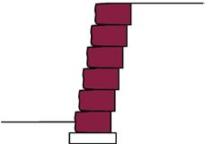
Xfa = widthb + H/3 x tan (0-90) = 20 + 72/3 x tan (100.6-90) = 24.5 in. 4a = H/3 = 72 / 3 = 24 in.
SUMMARY OF FORCES ACTING ON THE WALL
Active earth pressure is acting on the back of the wall. The horizontal component of this force is the driving force that would produce sliding or overturning of the wall. In this example, the vertical component of this same force acts downward and is a stabilizing force.
The weight of the PMB units is a stabilizing force.
A force equal and opposite to the weight of the PMB units and the vertical component of the active earth pressure is provided by the foundation soils and acts on the bottom of the wall. This force, sometimes called the bearing resistance force, is offset from the center of the base of the wall. The offset distance (e) is the eccentricity of the of the force required to maintain equilibrium and keep the wall from overturning.
Friction at the bottom of the wall acts opposite to the horizontal component of the active earth pressure.
6 PRECAST MODULAR BLOCK DESIGN MANUAL VOLUME 1: GRAVITY WALLS Example 1U.S. CUSTOMARY UNITSA6
7 PRECAST MODULAR BLOCK DESIGN MANUAL VOLUME 1: GRAVITY WALLS U.S. CUSTOMARY UNITS A7Example 1
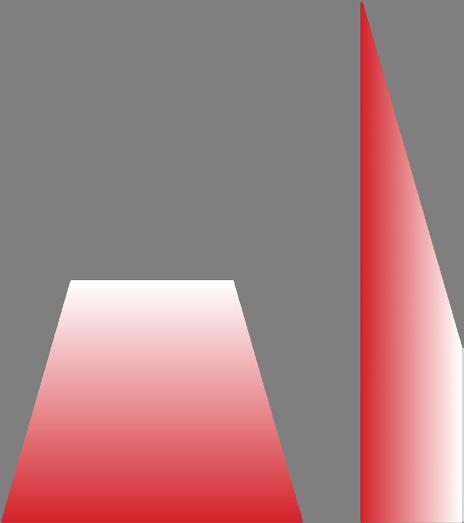
8 PRECAST MODULAR BLOCK DESIGN MANUAL VOLUME 1: GRAVITY WALLS Example 1U.S. CUSTOMARY UNITSA8
9 PRECAST MODULAR BLOCK DESIGN MANUAL VOLUME 1: GRAVITY WALLS U.S. CUSTOMARY UNITS A9Example 1
10 PRECAST MODULAR BLOCK DESIGN MANUAL VOLUME 1: GRAVITY WALLS Example 1U.S. CUSTOMARY UNITSA10
11 PRECAST MODULAR BLOCK DESIGN MANUAL VOLUME 1: GRAVITY WALLS U.S. CUSTOMARY UNITS A11Example 1


12 PRECAST MODULAR BLOCK DESIGN MANUAL VOLUME 1: GRAVITY WALLS Example 1U.S. CUSTOMARY UNITSA12
13 PRECAST MODULAR BLOCK DESIGN MANUAL VOLUME 1: GRAVITY WALLS U.S. CUSTOMARY UNITS A13Example 1
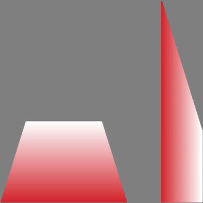
14 PRECAST MODULAR BLOCK DESIGN MANUAL VOLUME 1: GRAVITY WALLS Example 1U.S. CUSTOMARY UNITSA14
15 PRECAST MODULAR BLOCK DESIGN MANUAL VOLUME 1: GRAVITY WALLS U.S. CUSTOMARY UNITS A15Example 1
16 PRECAST MODULAR BLOCK DESIGN MANUAL VOLUME 1: GRAVITY WALLS Example 1U.S. CUSTOMARY UNITSA16

17 PRECAST MODULAR BLOCK DESIGN MANUAL VOLUME 1: GRAVITY WALLS U.S. CUSTOMARY UNITS A17Example 1
EXAMPLE 2


18 PRECAST MODULAR BLOCK DESIGN MANUAL VOLUME 1: GRAVITY WALLS Example 2U.S. CUSTOMARY UNITSA18
19 PRECAST MODULAR BLOCK DESIGN MANUAL VOLUME 1: GRAVITY WALLS U.S. CUSTOMARY UNITS A19Example 2
20 PRECAST MODULAR BLOCK DESIGN MANUAL VOLUME 1: GRAVITY WALLS Example 2U.S. CUSTOMARY UNITSA20
21 PRECAST MODULAR BLOCK DESIGN MANUAL VOLUME 1: GRAVITY WALLS U.S. CUSTOMARY UNITS A21Example 2
22 PRECAST MODULAR BLOCK DESIGN MANUAL VOLUME 1: GRAVITY WALLS Example 2U.S. CUSTOMARY UNITSA22
23 PRECAST MODULAR BLOCK DESIGN MANUAL VOLUME 1: GRAVITY WALLS U.S. CUSTOMARY UNITS A23Example 2
24 PRECAST MODULAR BLOCK DESIGN MANUAL VOLUME 1: GRAVITY WALLS Example 2U.S. CUSTOMARY UNITSA24

25 PRECAST MODULAR BLOCK DESIGN MANUAL VOLUME 1: GRAVITY WALLS U.S. CUSTOMARY UNITS A25Example 2

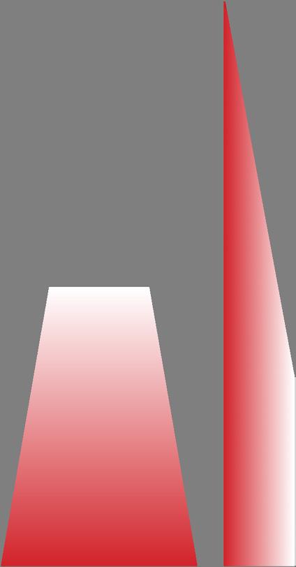
26 PRECAST MODULAR BLOCK DESIGN MANUAL VOLUME 1: GRAVITY WALLS Example 2U.S. CUSTOMARY UNITSA26

27 PRECAST MODULAR BLOCK DESIGN MANUAL VOLUME 1: GRAVITY WALLS U.S. CUSTOMARY UNITS A27Example 2
28 PRECAST MODULAR BLOCK DESIGN MANUAL VOLUME 1: GRAVITY WALLS Example 2U.S. CUSTOMARY UNITSA28
29 PRECAST MODULAR BLOCK DESIGN MANUAL VOLUME 1: GRAVITY WALLS U.S. CUSTOMARY UNITS A29Example 2
30 PRECAST MODULAR BLOCK DESIGN MANUAL VOLUME 1: GRAVITY WALLS Example 2U.S. CUSTOMARY UNITSA30
31 PRECAST MODULAR BLOCK DESIGN MANUAL VOLUME 1: GRAVITY WALLS U.S. CUSTOMARY UNITS A31Example 2
32 PRECAST MODULAR BLOCK DESIGN MANUAL VOLUME 1: GRAVITY WALLS Example 2U.S. CUSTOMARY UNITSA32
33 PRECAST MODULAR BLOCK DESIGN MANUAL VOLUME 1: GRAVITY WALLS U.S. CUSTOMARY UNITS A33Example 2
34 PRECAST MODULAR BLOCK DESIGN MANUAL VOLUME 1: GRAVITY WALLS Example 2U.S. CUSTOMARY UNITSA34


35 PRECAST MODULAR BLOCK DESIGN MANUAL VOLUME 1: GRAVITY WALLS U.S. CUSTOMARY UNITS A35Example 2
36 PRECAST MODULAR BLOCK DESIGN MANUAL VOLUME 1: GRAVITY WALLS Example 2U.S. CUSTOMARY UNITSA36
37 PRECAST MODULAR BLOCK DESIGN MANUAL VOLUME 1: GRAVITY WALLS U.S. CUSTOMARY UNITS A37Example 2
38 PRECAST MODULAR BLOCK DESIGN MANUAL VOLUME 1: GRAVITY WALLS Example 2U.S. CUSTOMARY UNITSA38
39 PRECAST MODULAR BLOCK DESIGN MANUAL VOLUME 1: GRAVITY WALLS U.S. CUSTOMARY UNITS A39Example 2

40 PRECAST MODULAR BLOCK DESIGN MANUAL VOLUME 1: GRAVITY WALLS Example 2U.S. CUSTOMARY UNITSA40
41 PRECAST MODULAR BLOCK DESIGN MANUAL VOLUME 1: GRAVITY WALLS U.S. CUSTOMARY UNITS A41Example 2
42 PRECAST MODULAR BLOCK DESIGN MANUAL VOLUME 1: GRAVITY WALLS Example 2U.S. CUSTOMARY UNITSA42
43 PRECAST MODULAR BLOCK DESIGN MANUAL VOLUME 1: GRAVITY WALLS U.S. CUSTOMARY UNITS A43Example 2
44
PRECAST MODULAR BLOCK DESIGN MANUAL VOLUME 1: GRAVITY WALLS
Example 2U.S. CUSTOMARY UNITSA44
45 PRECAST MODULAR BLOCK DESIGN MANUAL VOLUME 1: GRAVITY WALLS U.S. CUSTOMARY UNITS A45Example 2
46 PRECAST MODULAR BLOCK DESIGN MANUAL VOLUME 1: GRAVITY WALLS Example 2U.S. CUSTOMARY UNITSA46

47 PRECAST MODULAR BLOCK DESIGN MANUAL VOLUME 1: GRAVITY WALLS U.S. CUSTOMARY UNITS A47Example 2
48 PRECAST MODULAR BLOCK DESIGN MANUAL VOLUME 1: GRAVITY WALLS Example 2U.S. CUSTOMARY UNITSA48
49 PRECAST MODULAR BLOCK DESIGN MANUAL VOLUME 1: GRAVITY WALLS U.S. CUSTOMARY UNITS A49Example 2
50 PRECAST MODULAR BLOCK DESIGN MANUAL VOLUME 1: GRAVITY WALLS Example 2U.S. CUSTOMARY UNITSA50
51 PRECAST
MODULAR
BLOCK
DESIGN MANUAL VOLUME
1:
GRAVITY
WALLS U.S. CUSTOMARY UNITS A51Example 2
52 PRECAST MODULAR BLOCK DESIGN MANUAL VOLUME 1: GRAVITY WALLS Example 2U.S. CUSTOMARY UNITSA52
53 PRECAST MODULAR BLOCK DESIGN MANUAL VOLUME 1: GRAVITY WALLS U.S. CUSTOMARY UNITS A53Example 2

54 PRECAST MODULAR BLOCK DESIGN MANUAL VOLUME 1: GRAVITY WALLS Example 2U.S. CUSTOMARY UNITSA54
55 PRECAST MODULAR BLOCK DESIGN MANUAL VOLUME 1: GRAVITY WALLS U.S. CUSTOMARY UNITS A55Example 2
56 PRECAST MODULAR BLOCK DESIGN MANUAL VOLUME 1: GRAVITY WALLS Example 2U.S. CUSTOMARY UNITSA56
57 PRECAST MODULAR BLOCK DESIGN MANUAL VOLUME 1: GRAVITY WALLS U.S. CUSTOMARY UNITS A57Example 2
58 PRECAST MODULAR BLOCK DESIGN MANUAL VOLUME 1: GRAVITY WALLS Example 2U.S. CUSTOMARY UNITSA58
59 PRECAST MODULAR BLOCK DESIGN MANUAL VOLUME 1: GRAVITY WALLS U.S. CUSTOMARY UNITS A59Example 2
60 PRECAST MODULAR BLOCK DESIGN MANUAL VOLUME 1: GRAVITY WALLS Example 2U.S. CUSTOMARY UNITSA60


61 PRECAST MODULAR BLOCK DESIGN MANUAL VOLUME 1: GRAVITY WALLS U.S. CUSTOMARY UNITS A61Example 2
EXAMPLE 3

62 PRECAST MODULAR BLOCK DESIGN MANUAL VOLUME 1: GRAVITY WALLS Example 3U.S. CUSTOMARY UNITSA62
63 PRECAST MODULAR BLOCK DESIGN MANUAL VOLUME 1: GRAVITY WALLS U.S. CUSTOMARY UNITS A63Example 3
64 PRECAST MODULAR BLOCK DESIGN MANUAL VOLUME 1: GRAVITY WALLS Example 3U.S. CUSTOMARY UNITSA64
65 PRECAST MODULAR BLOCK DESIGN MANUAL VOLUME 1: GRAVITY WALLS U.S. CUSTOMARY UNITS A65Example 3
66 PRECAST MODULAR BLOCK DESIGN MANUAL VOLUME 1: GRAVITY WALLS Example 3U.S. CUSTOMARY UNITSA66
67 PRECAST MODULAR BLOCK DESIGN MANUAL VOLUME 1: GRAVITY WALLS U.S. CUSTOMARY UNITS A67Example 3

68 PRECAST MODULAR BLOCK DESIGN MANUAL VOLUME 1: GRAVITY WALLS Example 3U.S. CUSTOMARY UNITSA68

69 PRECAST MODULAR BLOCK DESIGN MANUAL VOLUME 1: GRAVITY WALLS U.S. CUSTOMARY UNITS A69Example 3
70 PRECAST MODULAR BLOCK DESIGN MANUAL VOLUME 1: GRAVITY WALLS Example 3U.S. CUSTOMARY UNITSA70

71 PRECAST MODULAR BLOCK DESIGN MANUAL VOLUME 1: GRAVITY WALLS U.S. CUSTOMARY UNITS A71Example 3
72 PRECAST MODULAR BLOCK DESIGN MANUAL VOLUME 1: GRAVITY WALLS Example 3U.S. CUSTOMARY UNITSA72
73 PRECAST MODULAR BLOCK DESIGN MANUAL VOLUME 1: GRAVITY WALLS U.S. CUSTOMARY UNITS A73Example 3
74 PRECAST MODULAR BLOCK DESIGN MANUAL VOLUME 1: GRAVITY WALLS Example 3U.S. CUSTOMARY UNITSA74
75 PRECAST MODULAR BLOCK DESIGN MANUAL VOLUME 1: GRAVITY WALLS U.S. CUSTOMARY UNITS A75Example 3
76 PRECAST MODULAR BLOCK DESIGN MANUAL VOLUME 1: GRAVITY WALLS Example 3U.S. CUSTOMARY UNITSA76
77 PRECAST MODULAR BLOCK DESIGN MANUAL VOLUME 1: GRAVITY WALLS U.S. CUSTOMARY UNITS A77Example 3
78 PRECAST MODULAR BLOCK DESIGN MANUAL VOLUME 1: GRAVITY WALLS Example 3U.S. CUSTOMARY UNITSA78
79 PRECAST MODULAR BLOCK DESIGN MANUAL VOLUME 1: GRAVITY WALLS U.S. CUSTOMARY UNITS A79Example 3
80 PRECAST MODULAR BLOCK DESIGN MANUAL VOLUME 1: GRAVITY WALLS Example 3U.S. CUSTOMARY UNITSA80
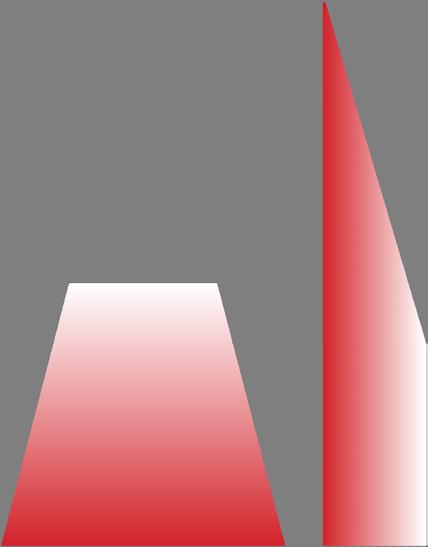
81 PRECAST MODULAR BLOCK DESIGN MANUAL VOLUME 1: GRAVITY WALLS U.S. CUSTOMARY UNITS A81Example 3

82 PRECAST MODULAR BLOCK DESIGN MANUAL VOLUME 1: GRAVITY WALLS Example 3U.S. CUSTOMARY UNITSA82
83 PRECAST MODULAR BLOCK DESIGN MANUAL VOLUME 1: GRAVITY WALLS U.S. CUSTOMARY UNITS A83Example 3
84 PRECAST MODULAR BLOCK DESIGN MANUAL VOLUME 1: GRAVITY WALLS Example 3U.S. CUSTOMARY UNITSA84
85 PRECAST MODULAR BLOCK DESIGN MANUAL VOLUME 1: GRAVITY WALLS U.S. CUSTOMARY UNITS A85Example 3
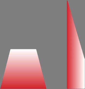
86 PRECAST MODULAR BLOCK DESIGN MANUAL VOLUME 1: GRAVITY WALLS Example 3U.S. CUSTOMARY UNITSA86

87 PRECAST MODULAR BLOCK DESIGN MANUAL VOLUME 1: GRAVITY WALLS U.S. CUSTOMARY UNITS A87Example 3
88 PRECAST MODULAR BLOCK DESIGN MANUAL VOLUME 1: GRAVITY WALLS Example 3U.S. CUSTOMARY UNITSA88
89 PRECAST MODULAR BLOCK DESIGN MANUAL VOLUME 1: GRAVITY WALLS U.S. CUSTOMARY UNITS A89Example 3
90 PRECAST MODULAR BLOCK DESIGN MANUAL VOLUME 1: GRAVITY WALLS Example 3U.S. CUSTOMARY UNITSA90
APPENDIX: B Examples 1-3 (Metric Units)
B1 PRECAST MODULAR BLOCK DESIGN MANUAL VOLUME 1: GRAVITY WALLS
EXAMPLE 1
B2 PRECAST MODULAR BLOCK DESIGN MANUAL VOLUME 1: GRAVITY WALLS Example 1METRIC UNITSB2
B3 PRECAST MODULAR BLOCK DESIGN MANUAL VOLUME 1: GRAVITY WALLS METRIC UNITS B3Example 1
B4 PRECAST MODULAR BLOCK DESIGN MANUAL VOLUME 1: GRAVITY WALLS Example 1METRIC UNITSB4
B5
PRECAST
MODULAR BLOCK DESIGN MANUAL VOLUME 1: GRAVITY WALLS METRIC UNITS B5Example 1
Active earth pressure increases linearly with depth. A resultant earth pressure force (equal to the area of the triangle shaped earth pressure diagram) can be calculated as follows:
Ea= ½ (ka y H) H = ½ x (0.228 x 18.85 x 1.829) x 1.829 = 7.188 kN/m
In Coulomb earth pressure theory, the earth pressure force is assumed to act at an angle (8) to the back of the wall. The earth pressure force can be separated into horizontal and vertical components:
Eah = Ea cos (90-0+8) = 7.188 cos (9.4 ° ) = 7.091 kN/m Eav = Ea sin (90-0+8) = 7.188 sin (9.4 ° ) = 1.174 kN/m
(PMB Unit 1 to Top)
Since the pressure on the back of the wall is triangular in shape, the resultant of the force acts on the back of the wall at½ H from the base. The point of application of the active earth pressure on the back of the wall is calculated as:
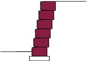
Xfa = widthb + H/3 x tan (0-90) = 0.508 + 1.829/3 x tan (100.6-90) = 0.622 m 4a = H/3 = 1.829 / 3 = 0.610 m
SUMMARY OF FORCES ACTING ON THE WALL
Active earth pressure is acting on the back of the wall. The horizontal component of this force is the driving force that would produce sliding or overturning of the wall. In this example, the vertical component of this same force acts downward and is a stabilizing force.
The weight of the PMB units is a stabilizing force.
A force equal and opposite to the weight of the PMB units and the vertical component of the active earth pressure is provided by the foundation soils and acts on the bottom of the wall. This force, sometimes called the bearing resistance force, is offset from the center of the base of the wall. The offset distance (e) is the eccentricity of the of the force required to maintain equilibrium and keep the wall from overturning.
Friction at the bottom of the wall acts opposite to the horizontal component of the active earth pressure.
B7 PRECAST MODULAR BLOCK DESIGN MANUAL VOLUME 1: GRAVITY WALLS METRIC UNITS B7Example 1
B8 PRECAST MODULAR BLOCK DESIGN MANUAL VOLUME 1: GRAVITY WALLS Example 1METRIC UNITSB8
B9 PRECAST MODULAR BLOCK DESIGN MANUAL VOLUME 1: GRAVITY WALLS METRIC UNITS B9Example 1
B10 PRECAST MODULAR BLOCK DESIGN MANUAL VOLUME 1: GRAVITY WALLS Example 1METRIC UNITSB10
B11 PRECAST MODULAR BLOCK DESIGN MANUAL VOLUME 1: GRAVITY WALLS METRIC UNITS B11Example 1
B12 PRECAST MODULAR BLOCK DESIGN MANUAL VOLUME 1: GRAVITY WALLS Example 1METRIC UNITSB12
B13
PRECAST
MODULAR BLOCK DESIGN MANUAL VOLUME 1: GRAVITY WALLS METRIC UNITS B13Example 1
B14 PRECAST MODULAR BLOCK DESIGN MANUAL VOLUME 1: GRAVITY WALLS Example 1METRIC UNITSB14
B15 PRECAST MODULAR BLOCK DESIGN MANUAL VOLUME 1: GRAVITY WALLS METRIC UNITS B15Example 1
B16 PRECAST MODULAR BLOCK DESIGN MANUAL VOLUME 1: GRAVITY WALLS Example 1METRIC UNITSB16
B17 PRECAST MODULAR BLOCK DESIGN MANUAL VOLUME 1: GRAVITY WALLS METRIC UNITS B17Example 1
EXAMPLE 2
B18 PRECAST MODULAR BLOCK DESIGN MANUAL VOLUME 1: GRAVITY WALLS Example 2METRIC UNITSB18
B19 PRECAST MODULAR BLOCK DESIGN MANUAL VOLUME 1: GRAVITY WALLS METRIC UNITS B19Example 2
B20 PRECAST MODULAR BLOCK DESIGN MANUAL VOLUME 1: GRAVITY WALLS Example 2METRIC UNITSB20
B21 PRECAST MODULAR BLOCK DESIGN MANUAL VOLUME 1: GRAVITY WALLS METRIC UNITS B21Example 2
B22 PRECAST MODULAR BLOCK DESIGN MANUAL VOLUME 1: GRAVITY WALLS Example 2METRIC UNITSB22
B23 PRECAST MODULAR BLOCK DESIGN MANUAL VOLUME 1: GRAVITY WALLS METRIC UNITS B23Example 2
B24 PRECAST MODULAR BLOCK DESIGN MANUAL VOLUME 1: GRAVITY WALLS Example 2METRIC UNITSB24
B25 PRECAST MODULAR BLOCK DESIGN MANUAL VOLUME 1: GRAVITY WALLS METRIC UNITS B25Example 2
B26 PRECAST MODULAR BLOCK DESIGN MANUAL VOLUME 1: GRAVITY WALLS Example 2METRIC UNITSB26


B27 PRECAST MODULAR BLOCK DESIGN MANUAL VOLUME 1: GRAVITY WALLS METRIC UNITS B27Example 2
B28 PRECAST MODULAR BLOCK DESIGN MANUAL VOLUME 1: GRAVITY WALLS Example 2METRIC UNITSB28
B29 PRECAST MODULAR BLOCK DESIGN MANUAL VOLUME 1: GRAVITY WALLS METRIC UNITS B29Example 2
B30 PRECAST MODULAR BLOCK DESIGN MANUAL VOLUME 1: GRAVITY WALLS Example 2METRIC UNITSB30
B31 PRECAST MODULAR BLOCK DESIGN MANUAL VOLUME 1: GRAVITY WALLS METRIC UNITS B31Example 2
B32 PRECAST MODULAR BLOCK DESIGN MANUAL VOLUME 1: GRAVITY WALLS Example 2METRIC UNITSB32
B33 PRECAST MODULAR BLOCK DESIGN MANUAL VOLUME 1: GRAVITY WALLS METRIC UNITS B33Example 2
B34 PRECAST MODULAR BLOCK DESIGN MANUAL VOLUME 1: GRAVITY WALLS Example 2METRIC UNITSB34
B35 PRECAST MODULAR BLOCK DESIGN MANUAL VOLUME 1: GRAVITY WALLS METRIC UNITS B35Example 2
B36 PRECAST MODULAR BLOCK DESIGN MANUAL VOLUME 1: GRAVITY WALLS Example 2METRIC UNITSB36
B37 PRECAST MODULAR BLOCK DESIGN MANUAL VOLUME 1: GRAVITY WALLS METRIC UNITS B37Example 2
B38 PRECAST MODULAR BLOCK DESIGN MANUAL VOLUME 1: GRAVITY WALLS Example 2METRIC UNITSB38
B39 PRECAST MODULAR BLOCK DESIGN MANUAL VOLUME 1: GRAVITY WALLS METRIC UNITS B39Example 2
B40 PRECAST MODULAR BLOCK DESIGN MANUAL VOLUME 1: GRAVITY WALLS Example 2METRIC UNITSB40
B41
PRECAST MODULAR BLOCK DESIGN MANUAL VOLUME
1:
GRAVITY
WALLS METRIC UNITS B41Example 2
B42 PRECAST MODULAR BLOCK DESIGN MANUAL VOLUME 1: GRAVITY WALLS Example 2METRIC UNITSB42
B43
PRECAST
MODULAR BLOCK DESIGN MANUAL VOLUME 1: GRAVITY WALLS METRIC UNITS B43Example 2
B44
PRECAST MODULAR BLOCK DESIGN MANUAL VOLUME 1: GRAVITY WALLS
Example 2METRIC UNITSB44
B45 PRECAST MODULAR BLOCK DESIGN MANUAL VOLUME 1: GRAVITY WALLS METRIC UNITS B45Example 2
B46 PRECAST MODULAR BLOCK DESIGN MANUAL VOLUME 1: GRAVITY WALLS Example 2METRIC UNITSB46
B47 PRECAST MODULAR BLOCK DESIGN MANUAL VOLUME 1: GRAVITY WALLS METRIC UNITS B47Example 2
B48 PRECAST MODULAR BLOCK DESIGN MANUAL VOLUME 1: GRAVITY WALLS Example 2METRIC UNITSB48
B49 PRECAST MODULAR BLOCK DESIGN MANUAL VOLUME 1: GRAVITY WALLS METRIC UNITS B49Example 2
B50 PRECAST MODULAR BLOCK DESIGN MANUAL VOLUME 1: GRAVITY WALLS Example 2METRIC UNITSB50
B51
PRECAST MODULAR BLOCK DESIGN MANUAL VOLUME 1: GRAVITY WALLS
METRIC UNITS B51Example 2
B52 PRECAST MODULAR BLOCK DESIGN MANUAL VOLUME 1: GRAVITY WALLS Example 2METRIC UNITSB52
B53 PRECAST MODULAR BLOCK DESIGN MANUAL VOLUME 1: GRAVITY WALLS METRIC UNITS B53Example 2
B54 PRECAST MODULAR BLOCK DESIGN MANUAL VOLUME 1: GRAVITY WALLS Example 2METRIC UNITSB54
B55 PRECAST MODULAR BLOCK DESIGN MANUAL VOLUME 1: GRAVITY WALLS METRIC UNITS B55Example 2
B56 PRECAST MODULAR BLOCK DESIGN MANUAL VOLUME 1: GRAVITY WALLS Example 2METRIC UNITSB56
B57 PRECAST MODULAR BLOCK DESIGN MANUAL VOLUME 1: GRAVITY WALLS METRIC UNITS B57Example 2
B58 PRECAST MODULAR BLOCK DESIGN MANUAL VOLUME 1: GRAVITY WALLS Example 2METRIC UNITSB58
B59 PRECAST MODULAR BLOCK DESIGN MANUAL VOLUME 1: GRAVITY WALLS METRIC UNITS B59Example 2
B60 PRECAST MODULAR BLOCK DESIGN MANUAL VOLUME 1: GRAVITY WALLS Example 2METRIC UNITSB60
B61 PRECAST MODULAR BLOCK DESIGN MANUAL VOLUME 1: GRAVITY WALLS METRIC UNITS B61Example 2
EXAMPLE 3
B62 PRECAST MODULAR BLOCK DESIGN MANUAL VOLUME 1: GRAVITY WALLS Example 3METRIC UNITSB62
B63 PRECAST MODULAR BLOCK DESIGN MANUAL VOLUME 1: GRAVITY WALLS METRIC UNITS B63Example 3
B64 PRECAST MODULAR BLOCK DESIGN MANUAL VOLUME 1: GRAVITY WALLS Example 3METRIC UNITSB64
B65 PRECAST MODULAR BLOCK DESIGN MANUAL VOLUME 1: GRAVITY WALLS METRIC UNITS B65Example 3
B66 PRECAST MODULAR BLOCK DESIGN MANUAL VOLUME 1: GRAVITY WALLS Example 3METRIC UNITSB66
B67 PRECAST MODULAR BLOCK DESIGN MANUAL VOLUME 1: GRAVITY WALLS METRIC UNITS B67Example 3
B68 PRECAST MODULAR BLOCK DESIGN MANUAL VOLUME 1: GRAVITY WALLS Example 3METRIC UNITSB68
B69
PRECAST
MODULAR BLOCK DESIGN MANUAL VOLUME 1: GRAVITY WALLS METRIC UNITS B69Example 3
B70 PRECAST MODULAR BLOCK DESIGN MANUAL VOLUME 1: GRAVITY WALLS Example 3METRIC UNITSB70
B71
PRECAST MODULAR BLOCK
DESIGN
MANUAL VOLUME
1: GRAVITY WALLS METRIC UNITS B71Example 3
B72 PRECAST MODULAR BLOCK DESIGN MANUAL VOLUME 1: GRAVITY WALLS Example 3METRIC UNITSB72
B73 PRECAST MODULAR BLOCK DESIGN MANUAL VOLUME 1: GRAVITY WALLS METRIC UNITS B73Example 3
B74 PRECAST MODULAR BLOCK DESIGN MANUAL VOLUME 1: GRAVITY WALLS Example 3METRIC UNITSB74
B75 PRECAST MODULAR BLOCK DESIGN MANUAL VOLUME 1: GRAVITY WALLS METRIC UNITS B75Example 3
B76 PRECAST MODULAR BLOCK DESIGN MANUAL VOLUME 1: GRAVITY WALLS Example 3METRIC UNITSB76
B77 PRECAST MODULAR BLOCK DESIGN MANUAL VOLUME 1: GRAVITY WALLS METRIC UNITS B77Example 3
B78 PRECAST MODULAR BLOCK DESIGN MANUAL VOLUME 1: GRAVITY WALLS Example 3METRIC UNITSB78
B79 PRECAST MODULAR BLOCK DESIGN MANUAL VOLUME 1: GRAVITY WALLS METRIC UNITS B79Example 3
B80 PRECAST MODULAR BLOCK DESIGN MANUAL VOLUME 1: GRAVITY WALLS Example 3METRIC UNITSB80
B81 PRECAST MODULAR BLOCK DESIGN MANUAL VOLUME 1: GRAVITY WALLS METRIC UNITS B81Example 3
B82 PRECAST MODULAR BLOCK DESIGN MANUAL VOLUME 1: GRAVITY WALLS Example 3METRIC UNITSB82
B83 PRECAST MODULAR BLOCK DESIGN MANUAL VOLUME 1: GRAVITY WALLS METRIC UNITS B83Example 3
B84 PRECAST MODULAR BLOCK DESIGN MANUAL VOLUME 1: GRAVITY WALLS Example 3METRIC UNITSB84
B85 PRECAST MODULAR BLOCK DESIGN MANUAL VOLUME 1: GRAVITY WALLS METRIC UNITS B85Example 3
B86 PRECAST MODULAR BLOCK DESIGN MANUAL VOLUME 1: GRAVITY WALLS Example 3METRIC UNITSB86
B87 PRECAST MODULAR BLOCK DESIGN MANUAL VOLUME 1: GRAVITY WALLS METRIC UNITS B87Example 3
B88
PRECAST MODULAR BLOCK DESIGN MANUAL VOLUME
1:
GRAVITY WALLS
Example 3METRIC UNITSB88
B89 PRECAST MODULAR BLOCK DESIGN MANUAL VOLUME 1: GRAVITY WALLS METRIC UNITS B89Example 3
B90 PRECAST MODULAR BLOCK DESIGN MANUAL VOLUME 1: GRAVITY WALLS Example 3METRIC UNITSB90
APPENDIX: C Graphical Coulomb Solution
C1 PRECAST MODULAR BLOCK DESIGN MANUAL VOLUME 1: GRAVITY WALLS
C2 PRECAST MODULAR BLOCK DESIGN MANUAL VOLUME 1: GRAVITY WALLS GRAPHICAL COULOMB SOLUTIONC2
C3 PRECAST MODULAR BLOCK DESIGN MANUAL VOLUME 1: GRAVITY WALLS GRAPHICAL COULOMB SOLUTION C3
C4 PRECAST MODULAR BLOCK DESIGN MANUAL VOLUME 1: GRAVITY WALLS GRAPHICAL COULOMB SOLUTIONC4
C5 PRECAST MODULAR BLOCK DESIGN MANUAL VOLUME 1: GRAVITY WALLS GRAPHICAL COULOMB SOLUTION C5
C6 PRECAST MODULAR BLOCK DESIGN MANUAL VOLUME 1: GRAVITY WALLS GRAPHICAL COULOMB SOLUTIONC6
C7 PRECAST MODULAR BLOCK DESIGN MANUAL VOLUME 1: GRAVITY WALLS GRAPHICAL COULOMB SOLUTION C7
C8 PRECAST MODULAR BLOCK DESIGN MANUAL VOLUME 1: GRAVITY WALLS GRAPHICAL COULOMB SOLUTIONC8
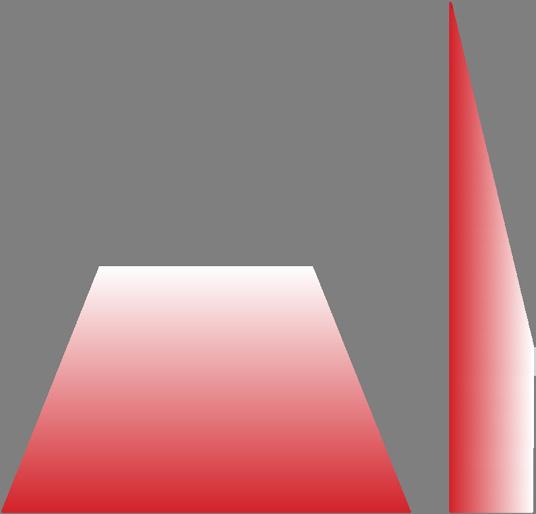
C9 PRECAST MODULAR BLOCK DESIGN MANUAL VOLUME 1: GRAVITY WALLS GRAPHICAL COULOMB SOLUTION C9
C10 PRECAST MODULAR BLOCK DESIGN MANUAL VOLUME 1: GRAVITY WALLS GRAPHICAL COULOMB SOLUTIONC10
C11 PRECAST MODULAR BLOCK DESIGN MANUAL VOLUME 1: GRAVITY WALLS GRAPHICAL COULOMB SOLUTION C11
C12 PRECAST MODULAR BLOCK DESIGN MANUAL VOLUME 1: GRAVITY WALLS GRAPHICAL COULOMB SOLUTIONC12
C13 PRECAST MODULAR BLOCK DESIGN MANUAL VOLUME 1: GRAVITY WALLS GRAPHICAL COULOMB SOLUTION C13


C14
PRECAST
MODULAR
BLOCK DESIGN MANUAL
VOLUME 1: GRAVITY
WALLS
GRAPHICAL COULOMB SOLUTIONC14
C15 PRECAST MODULAR BLOCK DESIGN MANUAL VOLUME 1: GRAVITY WALLS GRAPHICAL COULOMB SOLUTION C15
C16 PRECAST MODULAR BLOCK DESIGN MANUAL VOLUME 1: GRAVITY WALLS GRAPHICAL COULOMB SOLUTIONC16
C17 PRECAST MODULAR BLOCK DESIGN MANUAL VOLUME 1: GRAVITY WALLS GRAPHICAL COULOMB SOLUTION C17
C18 PRECAST MODULAR BLOCK DESIGN MANUAL VOLUME 1: GRAVITY WALLS GRAPHICAL COULOMB SOLUTIONC18
C19 PRECAST MODULAR BLOCK DESIGN MANUAL VOLUME 1: GRAVITY WALLS GRAPHICAL COULOMB SOLUTION C19
C20 PRECAST MODULAR BLOCK DESIGN MANUAL VOLUME 1: GRAVITY WALLS GRAPHICAL COULOMB SOLUTIONC20
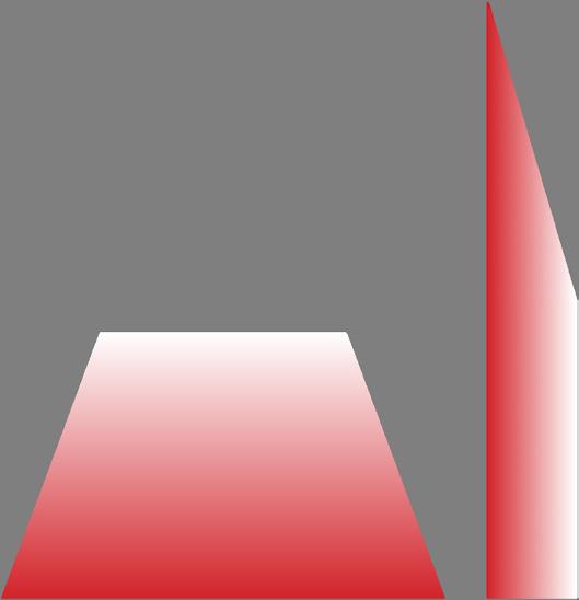
C21 PRECAST MODULAR BLOCK DESIGN MANUAL VOLUME 1: GRAVITY WALLS GRAPHICAL COULOMB SOLUTION C21
C22 PRECAST MODULAR BLOCK DESIGN MANUAL VOLUME 1: GRAVITY WALLS GRAPHICAL COULOMB SOLUTIONC22
C23 PRECAST MODULAR BLOCK DESIGN MANUAL VOLUME 1: GRAVITY WALLS GRAPHICAL COULOMB SOLUTION C23
C24 PRECAST MODULAR BLOCK DESIGN MANUAL VOLUME 1: GRAVITY WALLS GRAPHICAL COULOMB SOLUTIONC24
C25 PRECAST MODULAR BLOCK DESIGN MANUAL VOLUME 1: GRAVITY WALLS GRAPHICAL COULOMB SOLUTION C25
C26
PRECAST MODULAR BLOCK DESIGN MANUAL VOLUME
1:
GRAVITY WALLS
GRAPHICAL COULOMB SOLUTIONC26
C27 PRECAST MODULAR BLOCK DESIGN MANUAL VOLUME 1: GRAVITY WALLS GRAPHICAL COULOMB SOLUTION C27

C28 PRECAST MODULAR BLOCK DESIGN MANUAL VOLUME 1: GRAVITY WALLS GRAPHICAL COULOMB SOLUTIONC28

C29 PRECAST MODULAR BLOCK DESIGN MANUAL VOLUME 1: GRAVITY WALLS GRAPHICAL COULOMB SOLUTION C29
ABOUT THE AUTHORS
Jamie Johnson
Jamie has over 28 years of design experi ence in civil engineering. His profession al career began as a consulting engineer working for Benchmark Engineering, a civil and surveying firm in northern Michigan. While at Benchmark, Jamie was involved in every aspect of site design for both public and private projects. In 2006, Jamie joined Redi-Rock International where he has held multiple roles including Staff Engineer, Chief Engineer, and Director of Operations. He is currently Director of Innovation. Ja mie holds Bachelor and Master of Science Degrees in Civil Engineering from Virginia Tech and is a registered professional en gineer in the State of Michigan.

Nils Lindwall
Nils has over 23 years of experience in geotechnical and civil engineering. After completing his Bachelor of Science in Civil Engineering degree at Michigan Techno logical University in Houghton, Michigan, Nils completed his Master’s degree in ge otechnical engineering at the University of Washington in Seattle. He worked in both public- and private-sector consulting in both the Pacific Northwest and Midwest regions of the United States. A former Chief Engineer at Aster Brands, providing technical expertise for Redi-Rock and Ro setta precast modular blocks, Nils is cur rently a senior project manager at Spicer Group, a Michigan-based consulting engi neering firm. Nils is a licensed professional engineer in the State of Michigan.
John Clinton (“Clint”) Hines
Clint is a professional engineer with 29 years of experience, primarily in the retaining wall industry. He is the founder and president of J.C. Hines and Associ ates, a geotechnical design consulting firm specializing in the delivery of optimized retaining wall solutions for large-scale civil site development and infrastructure projects. With expertise in site develop ment construction, site development construction products sales, design/build retaining wall construction, geosynthetic design solutions and geotechnical design consulting, Clint has a unique background that combines the practical knowledge of construction cost with a broad under standing of effective earth retention design solutions. Clint’s professional resume includes work as design engineer of record on over 7 million square feet of retaining walls and earth retention struc tures throughout the United States. He has provided forensic engineering services for retaining wall failures for clients in the Midwestern and Southeastern United States. Clint is a graduate of the Univer sity of Cincinnati, College of Engineering, and is a registered professional engineer in 42 states.


PRECAST MODULAR BLOCK DESIGN MANUAL VOLUME 1: GRAVITY WALLS
PRECAST MODULAR BLOCK DESIGN MANUAL VOLUME 1: GRAVITY WALLS
blocks have been used to construct walls for millennia. There is something inherently simple about stacking large
on top of each other that just makes sense. If the
are big and heavy enough, they can be used to safely support retained
and anything else that might be on top of the
Relatively recently large precast concrete blocks, often called precast modular blocks or PMBs, have become widely available and are used to build retaining wall
for a wide variety of
by
who
with
for
who
to
when designing PMB
Precast
covers
Volume
Big
blocks
blocks
earth
wall.
structures
applications. Precast Modular Block Design Manual Volume 1: Gravity Walls was written
a trio of professional engineers
collectively have over 80 years of design experience,
a special emphasis on PMB walls, in order to help those who want to learn the fundamentals of large block retaining walls. It is part textbook and part workbook
wall designers
wish
follow, step by step, the process practicing engineers employ
walls.
Modular Block Design Manual
1: Gravity Walls is not brand specific. It
fundamental concepts applicable to all type of PMBs. Some topics in this manual include: This manual would be of interest to professional engineers, researchers, educators, and students. • PMB unit properties • Soil mechanics for walls • Determination of earth pressure acting on a wall • Modes of failure • Stability calculations • Construction details • Best practices • Several worked example problems (in US Customary and Metric units) • Graphical method to determine Coulomb earth pressure Published by Aster Brands ©2022 All Rights Reserved
