


+91 7022101157
ashuak0404@gmai.com
https://www.linkedin.com/in/ashwin-kumar-424a32208/ ar._.ashwin_kumar
Bangalore, Karnataka
As an architect, I am an organized individual who has a strong desire to learn and is a quick learner. I posses a genuine passion for designing spaces that connect people and the environment.
Since 2021, I have been working as a freelancer and have gained valuable experience in planning, conceptual design, 3D visualization, and interior design, both in the residential and commercial sectors. I am continuously seeking out new opportunities to broaden my knowledge of architecture and become a responsible and well-rounded architect.
My ultimate goal is to utilize my skills, abilities, enthusiasm to work collaboratively with a team that will help me cultivate my potential as both a professional and an individual. I am eager to contribute and enhance my growth in this exciting field.

ABOUT ME
I am Ashwin Kumar,
Hello
Education
• B.arch
VTU / HMS School Of Architecture
Tumkur
• Pre University
Sri Chaitanya PU College Tumkur
• High School
Sri Chaitanya Techno School Tumkur
Workshops
• AI In Architecture
• Virtual Reality
• 3D Printing
• Augmented Reality in Architecture
• BIM in architecture
• Sustainable Built Environment
• Origami In Architecture
• GRIHA Workshop
• Gap
• Digital illustration
Languages
• English
• Kannada
• Hindi
• Telugu
• Tamil
Ashwin Kumar T.S
04/04/2001 Bangalore
Professional Experience
Worked As an Architectural Intern at STUDIO DVARA in Jubilee Hills, Hyderabad. Also Worked at NANDHI ARCHITECTS in Koratagere, Tumkur.
I have gained Valuable experience in the field and worked to Various projects.
Experienced freelancer with a successful track record in residential and commercial projects. Skilled in time management, communication, and networking to deliver timely projects and collaborating effectively with clients.
Professional Skills
• Manual & Digital Sketching
• Model making
• Presentations
• Architectural Visualization
• Graphic design
• Architecture Photography
• Fast Learner
• Leadership
Academic Projects
Sem I -Bus Stop
Sem II -Pleader’s Residence

Certified Professional March 2022
Sem III -Row House & Container House
Sem IV -Apartment Design
Sem V -Art Gallery & Plaza Design
Sem VI -Nursing Home & Nursing College
Sem VII -Hotel Design
Sem VIII -Urban Design
Software Skills


CURRICULUM VITAE / CV
GEM
“Architecture
is a language that speaks to us through space, form, and light, conveying emotions and ideas without the need for words.”
- Louis Kahn
Row House
Semester 03 I 2020
Hotel
Semester 07 I 2022
Sketches CONTENTS
Art Gallery
Semester 05 I 2021
Janwada Farm House
Internship I 2024
01-04 05-14 15-20 21-28
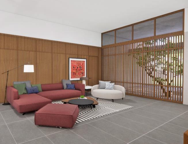
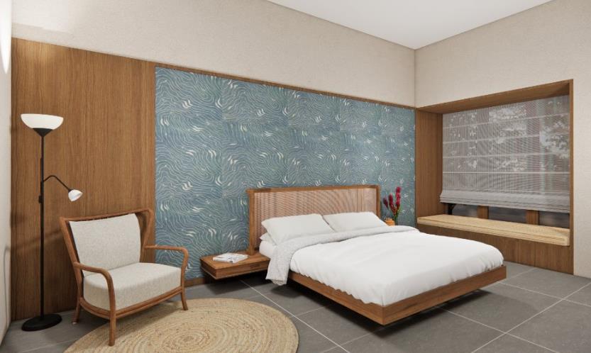
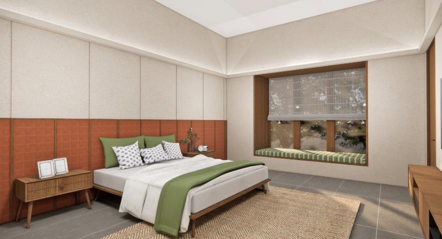
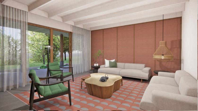
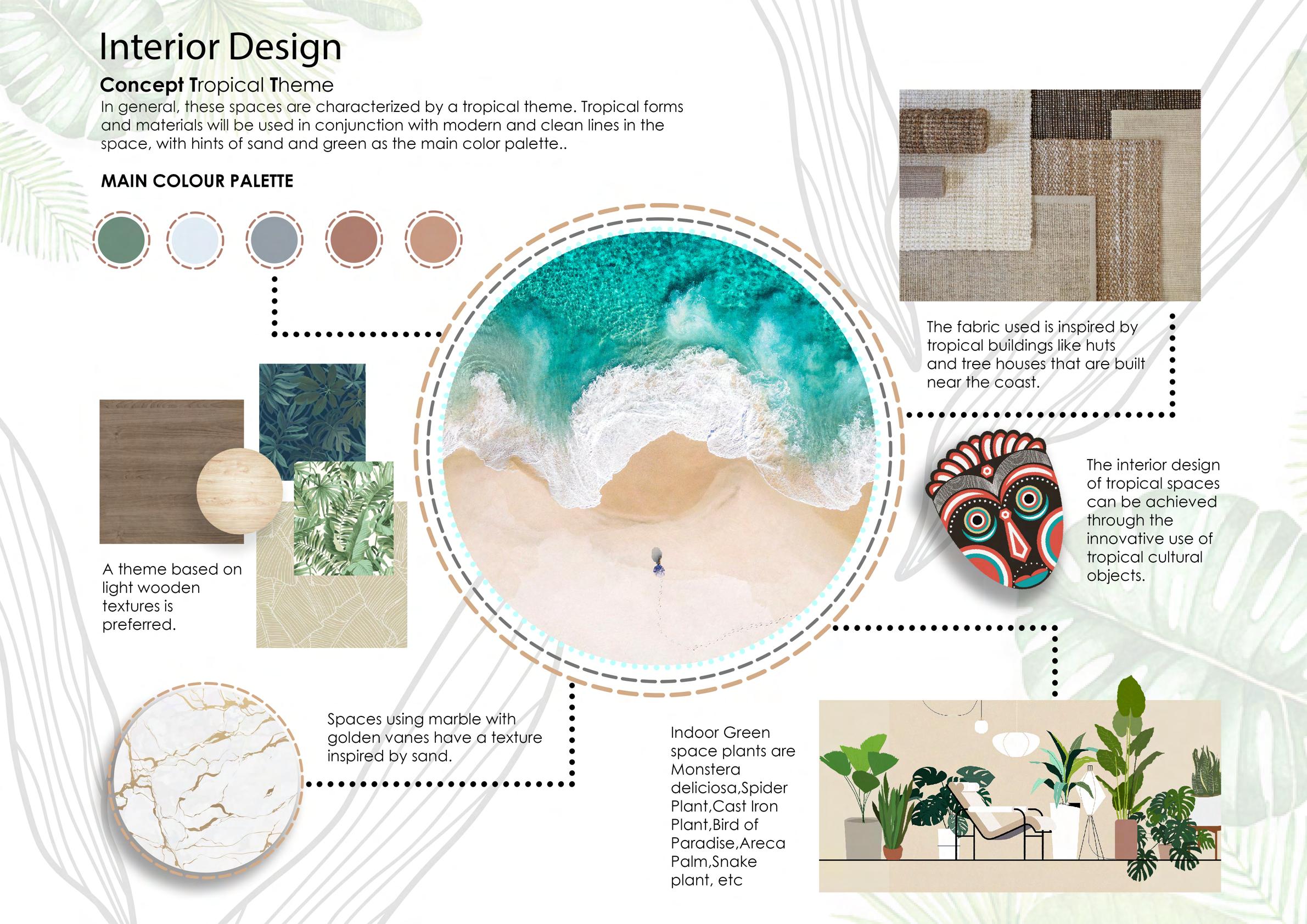
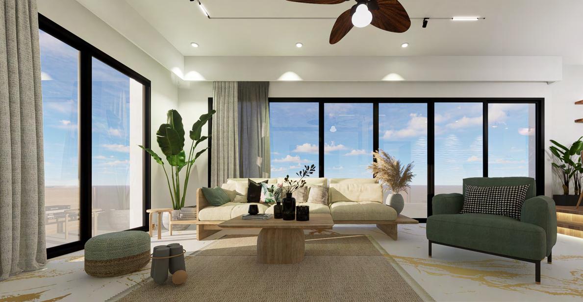
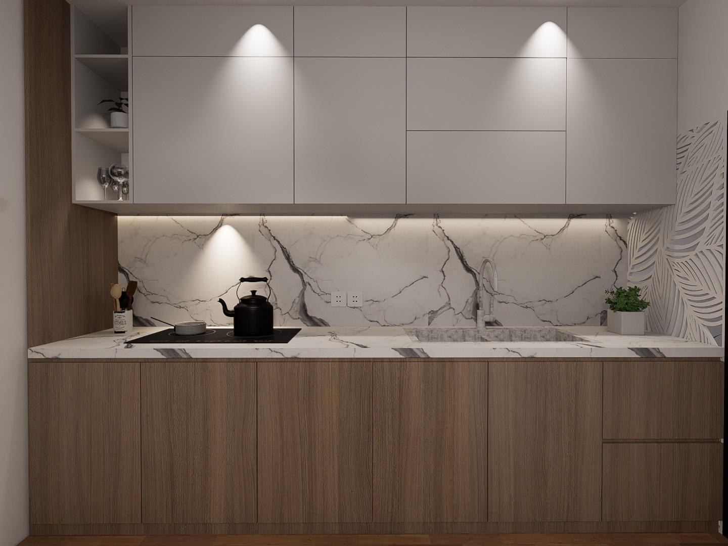
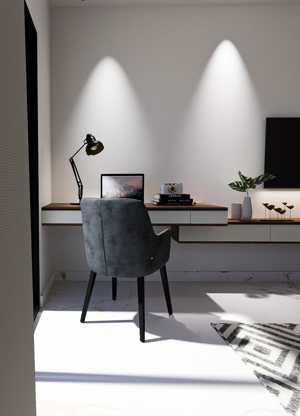
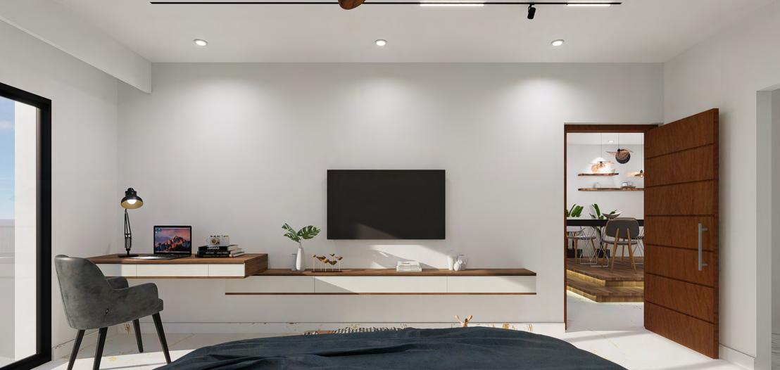
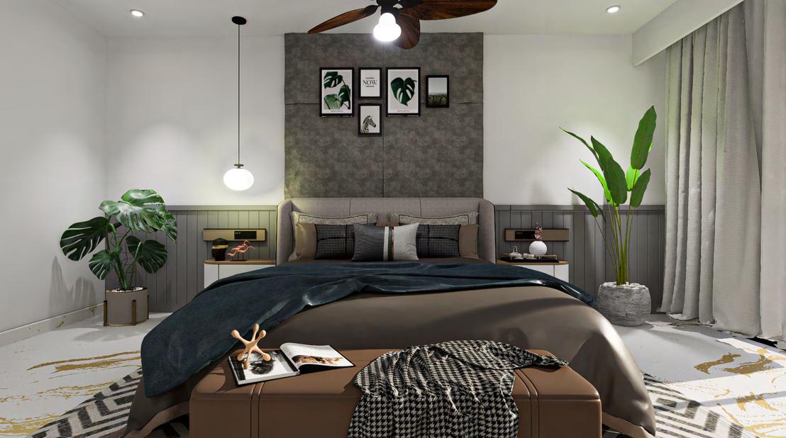
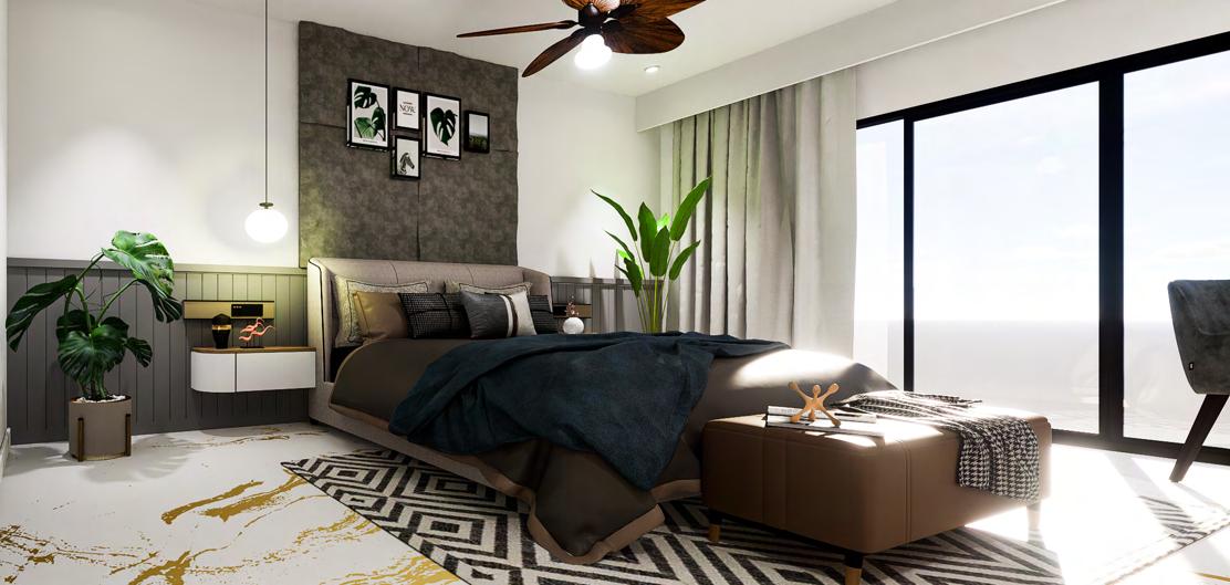
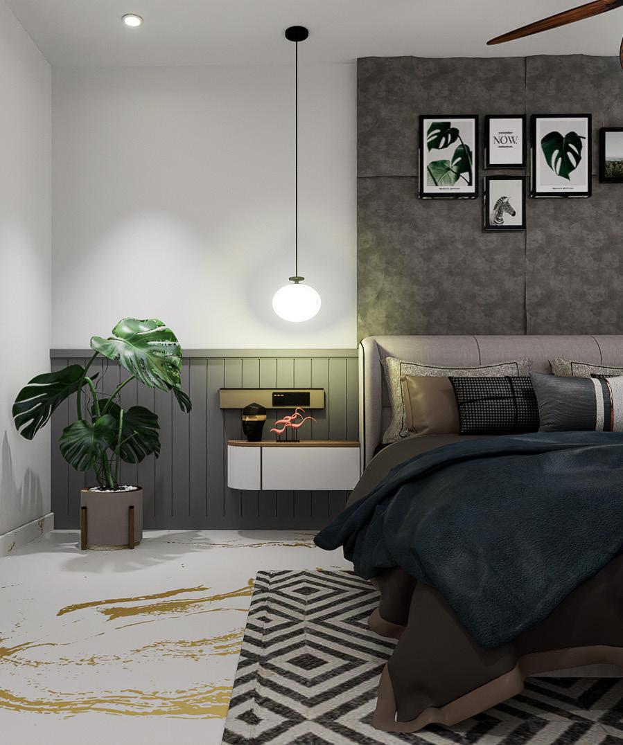
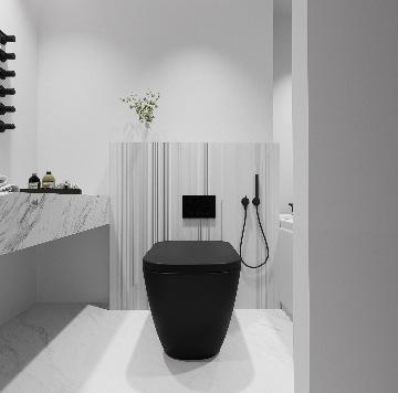
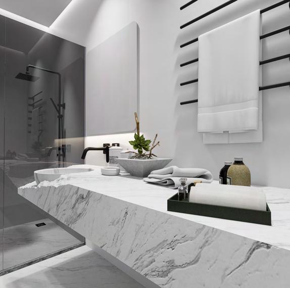
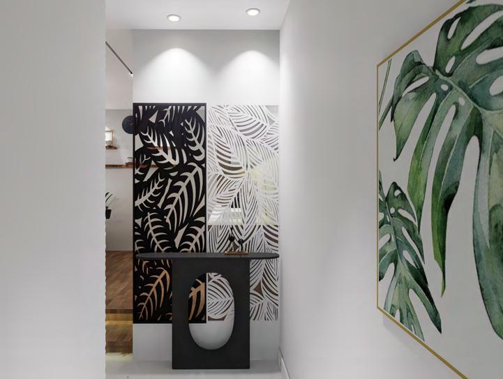
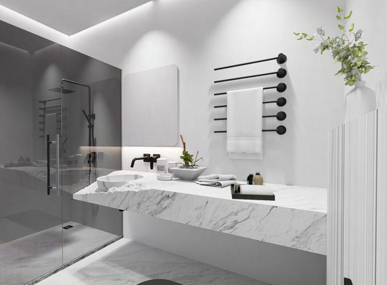
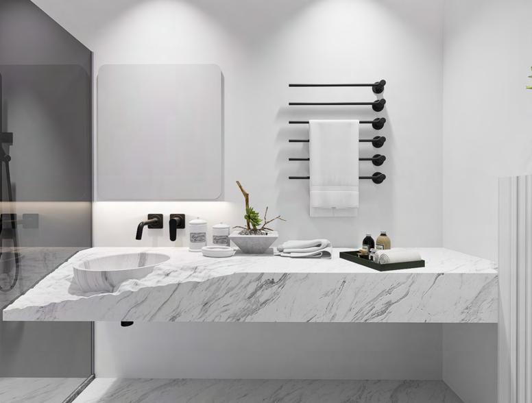
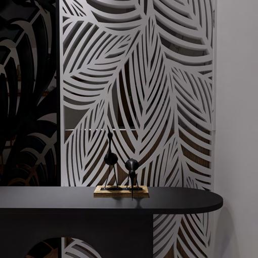
Interior Design
29-32
Working Drawing
33-34
35-36
CONTENTS/ SELECTED WORK
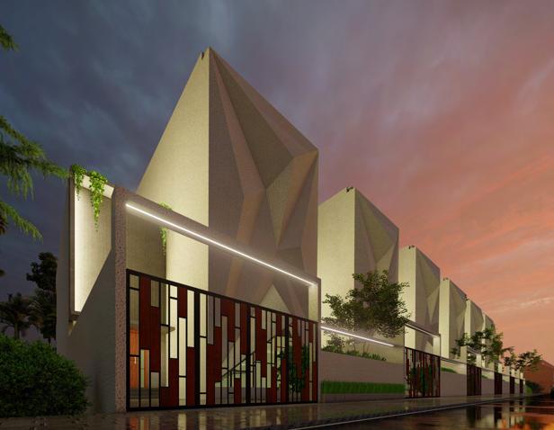
Row House 01
Row House
Academic project I Semester 03 I 2022
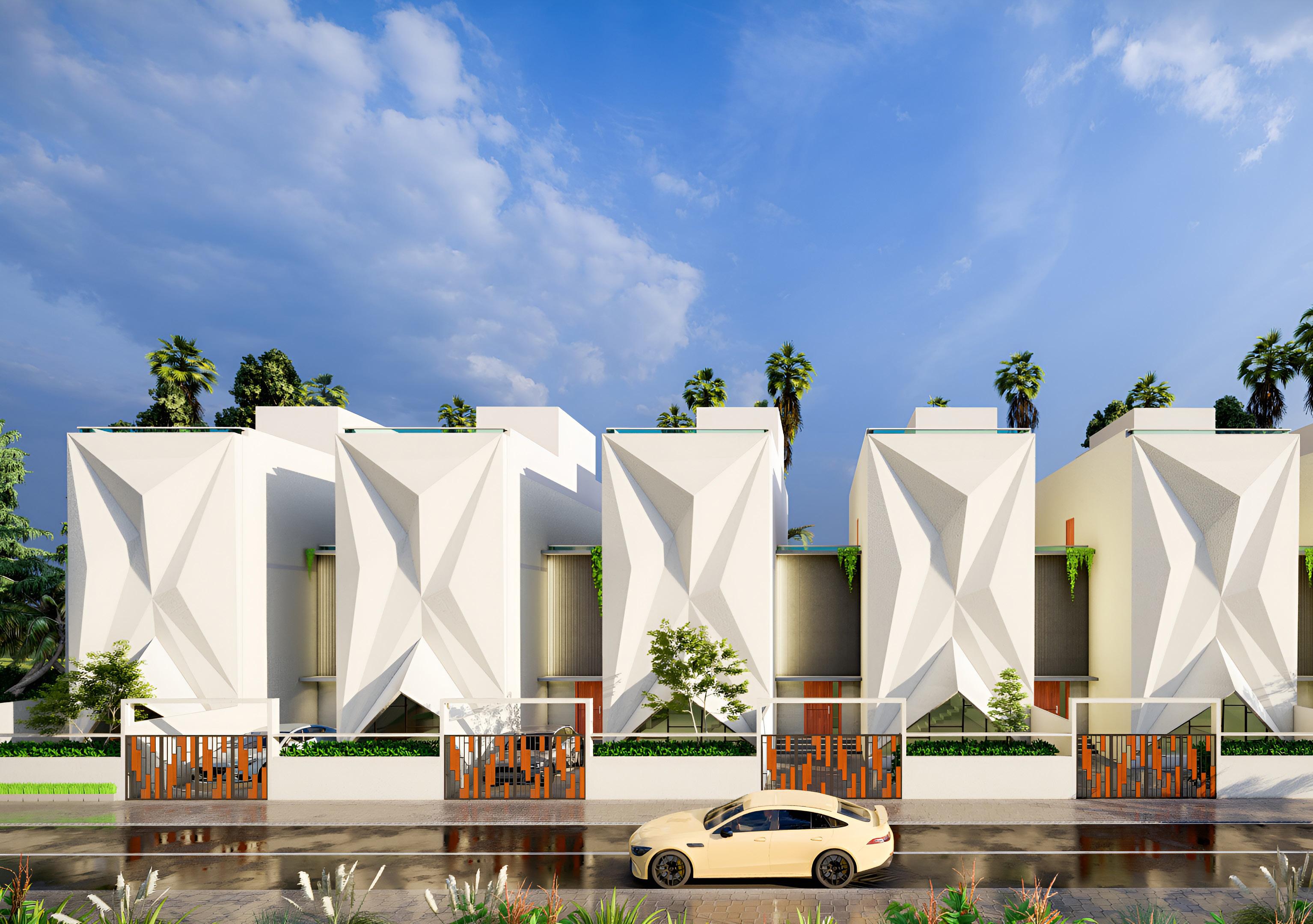
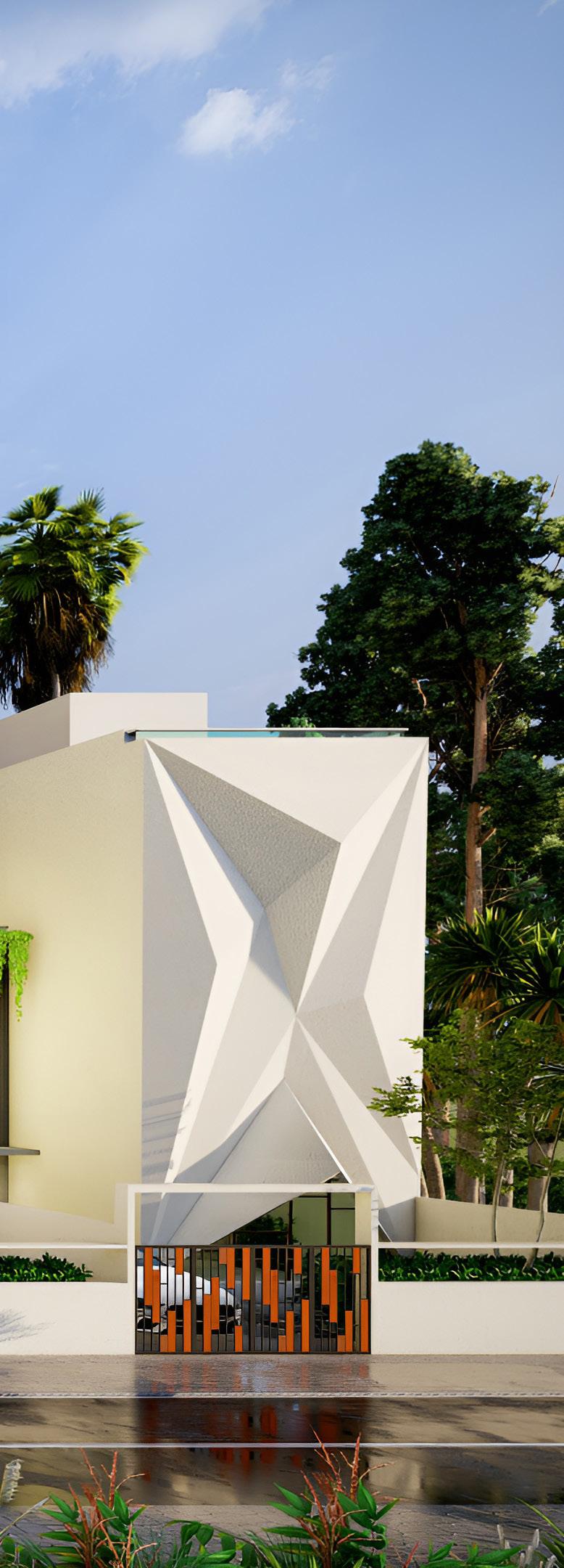
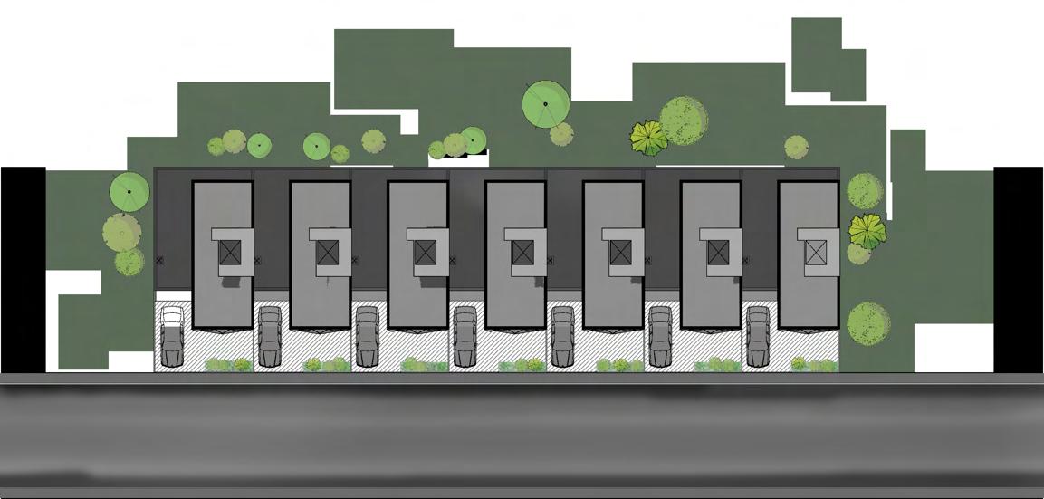
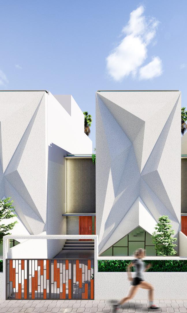
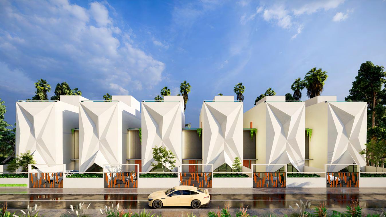
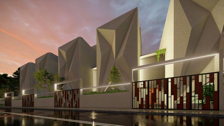
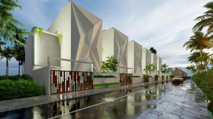
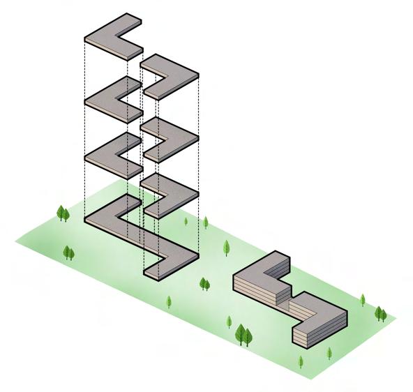
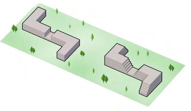
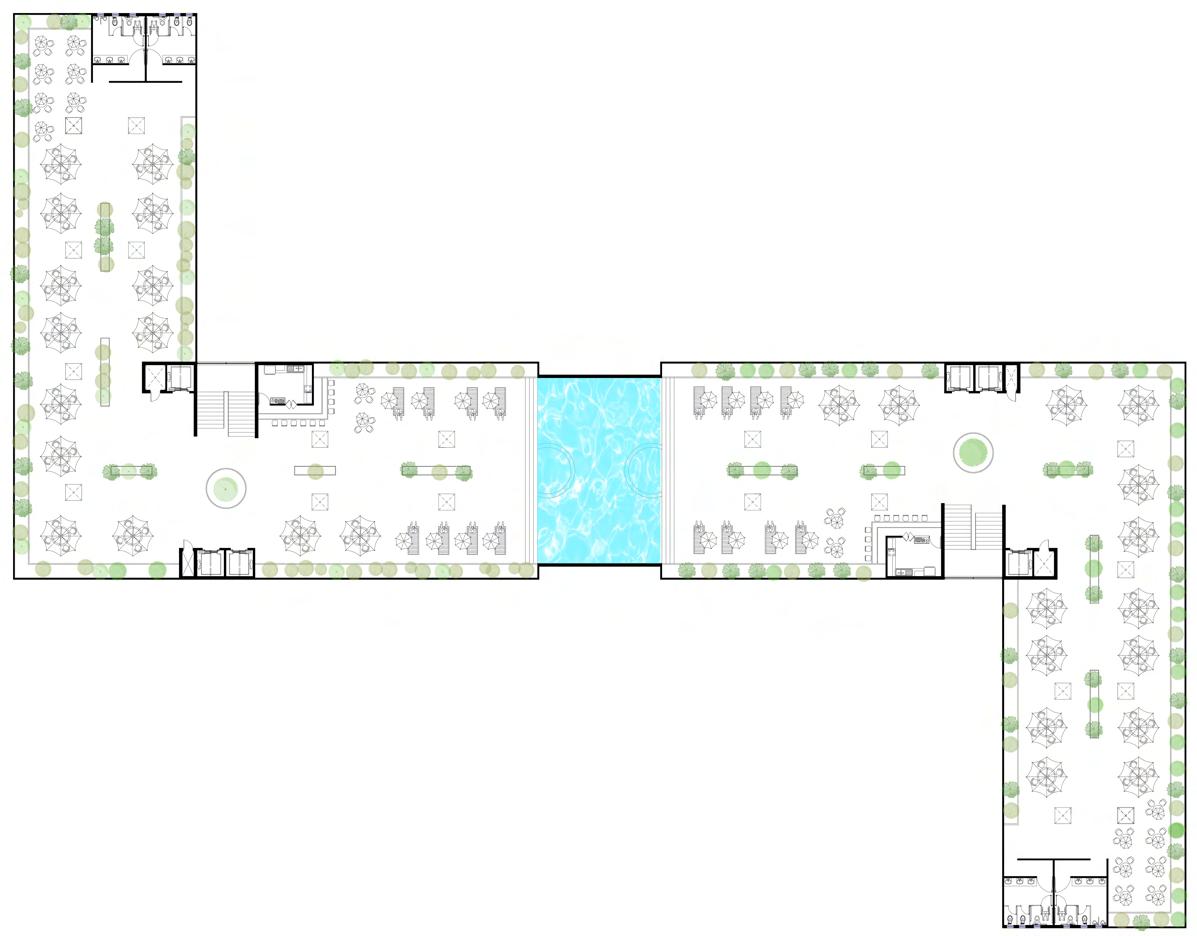
This row house design is located near a toll gate on the Tumkur to Bangalore highway. The site measures 60x18 meters and features a 9-meter wide road. The use of origami architecture creates a dynamic and ever-changing aesthetic for the buildings. A total of 6 row houses are included in the design, each with 3BHK and 1 home theatre.
The design emphasizes natural light and ventilation throughout each row house. Privacy, noise reduction, and energy efficiency are also important considerations in the design. The layout and arrangement of the buildings on the site are carefully planned. The changing shades and patterns with the movement of the sun enhance the visual appeal of the buildings.
This design offers a unique and visually stunning option for row house living. Overall, the design combines aesthetics, functionality, and sustainability to create a harmonious living environment.
Autocad I Sketchup I Lumion I Photoshop
Row House 02 01


Row house floor plans 03 2 1 3 4 5 6 10 7 8 9 1.
6sq M 2.
room
21sq M 3.
sq
4.
13
5.
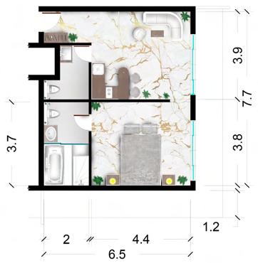
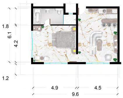
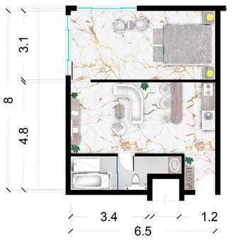
toilet - 4.5 sq M 6. Bedroom 1 - 20.6 sq M 7. Bedroom 2 - 20.6sq M 8. Bedroom 3 - 16.6 sq M 9. Home theatre - 19 sq M 10. Storeroom - 6 sq M Ground Floor Plan First Floor Plan Second Floor Plan Site Plan
Foyer -
Living
-
Dining - 6.2
M
Kitchen -
sq M
Common
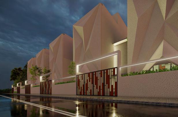
Row House Renders Render Images 04
02
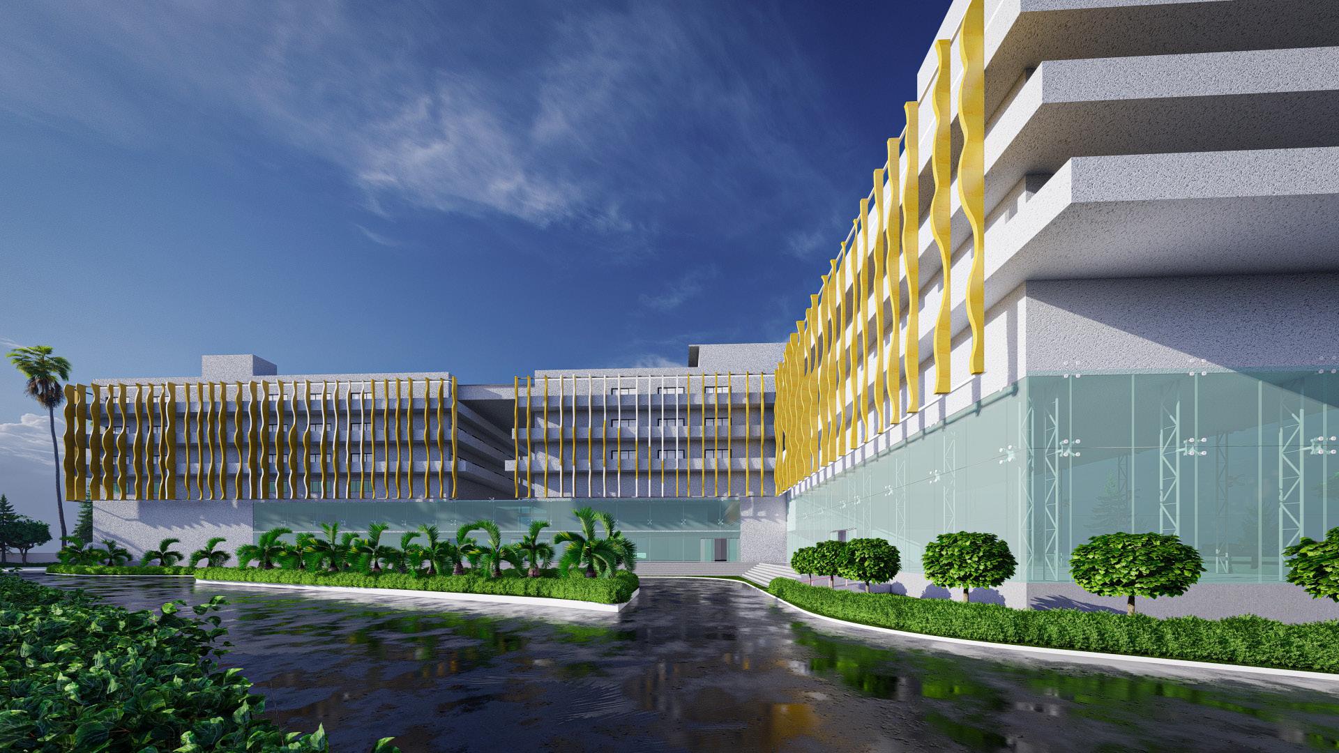
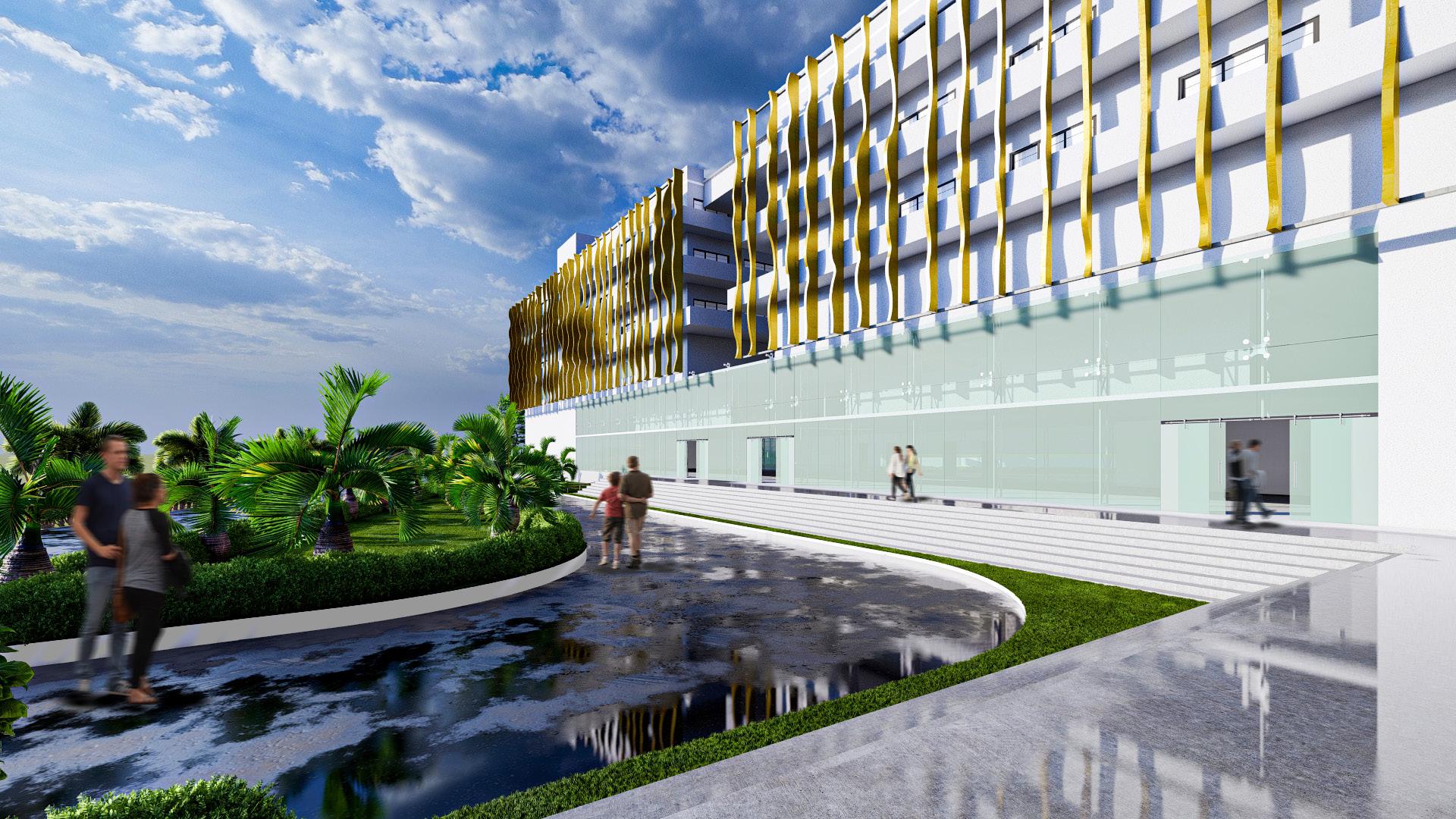
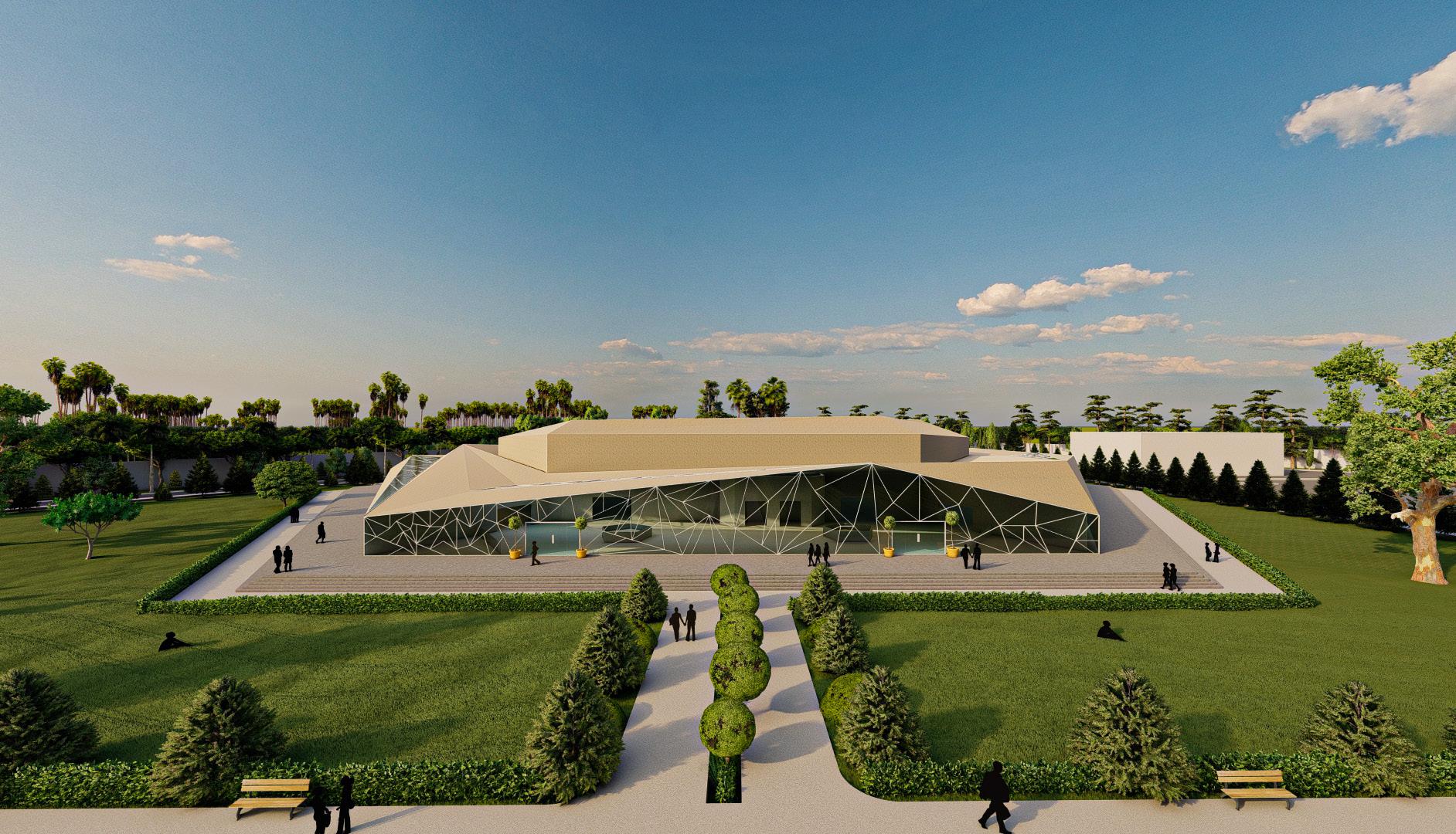
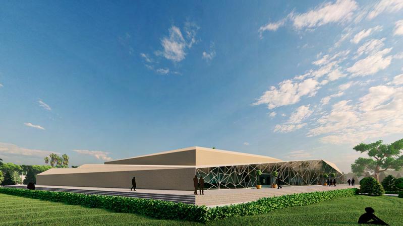
Hotel
Academic project I Semester 07 I 2022
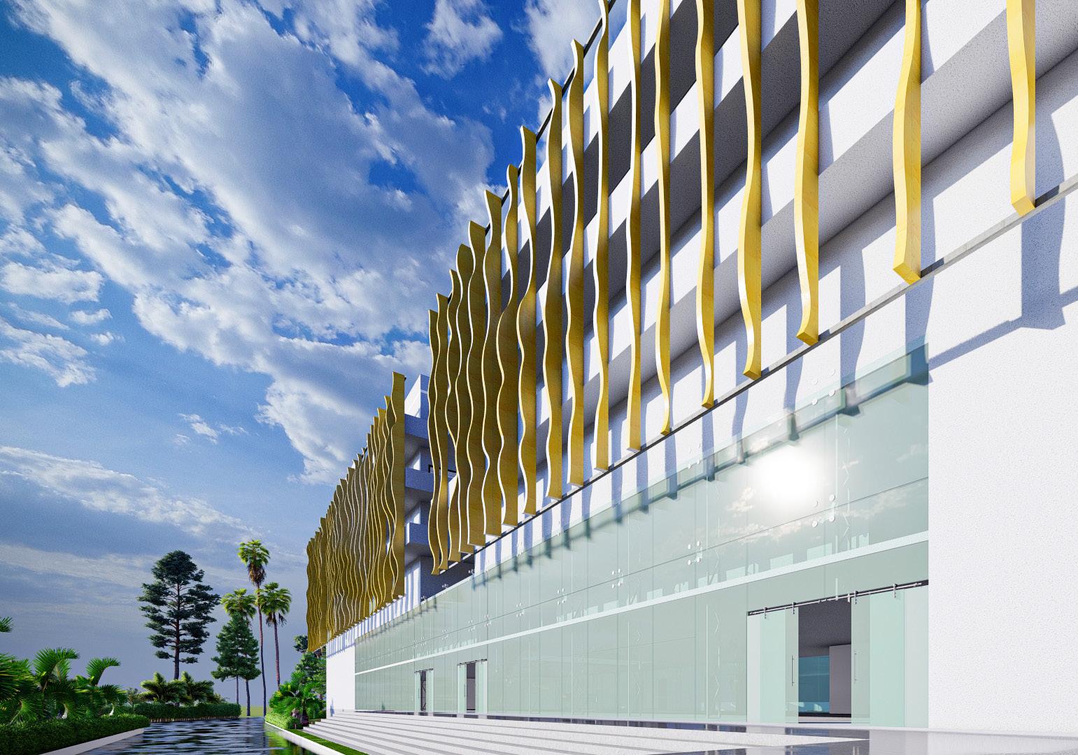
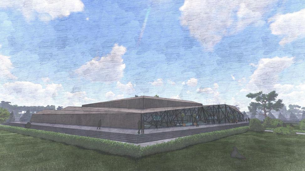
This hotel build features a dynamic facade that acts as the “skin” of the building, reducing heat gain from the sun and optimizing energy consumption for a sustainable and energy-efficient approach. The design prioritizes guest experience and efficient circulation, with well-planned interior spaces that enhance comfort. The dynamic facade adapts to environmental changes, further optimizing energy use. The project showcases a unique and innovative hotel design that blends sustainability and guest comfort in a functional and thoughtfully planned manner.
Autocad I Sketchup I Lumion I Photoshop
Illustrator I Procreate I D5 Render
Design Form :
Dynamic facades respond to environmental changes using advanced materials and control systems, optimizing energy efficiency and aesthetics. Building form is considered to make efficient use of space while minimizing waste and improving occupant comfort. Combining dynamic facades and innovative building form can lead to more sustainable and environmentally friendly structures. This approach can reduce energy consumption for lighting and cooling while improving the indoor environment. Overall, dynamic facades and innovative building form reduced environmental impact.
STAGE 1
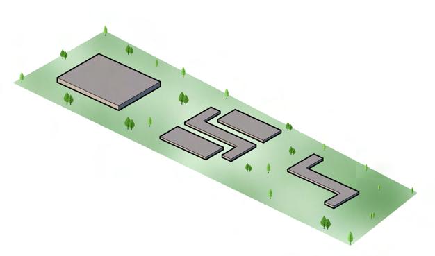
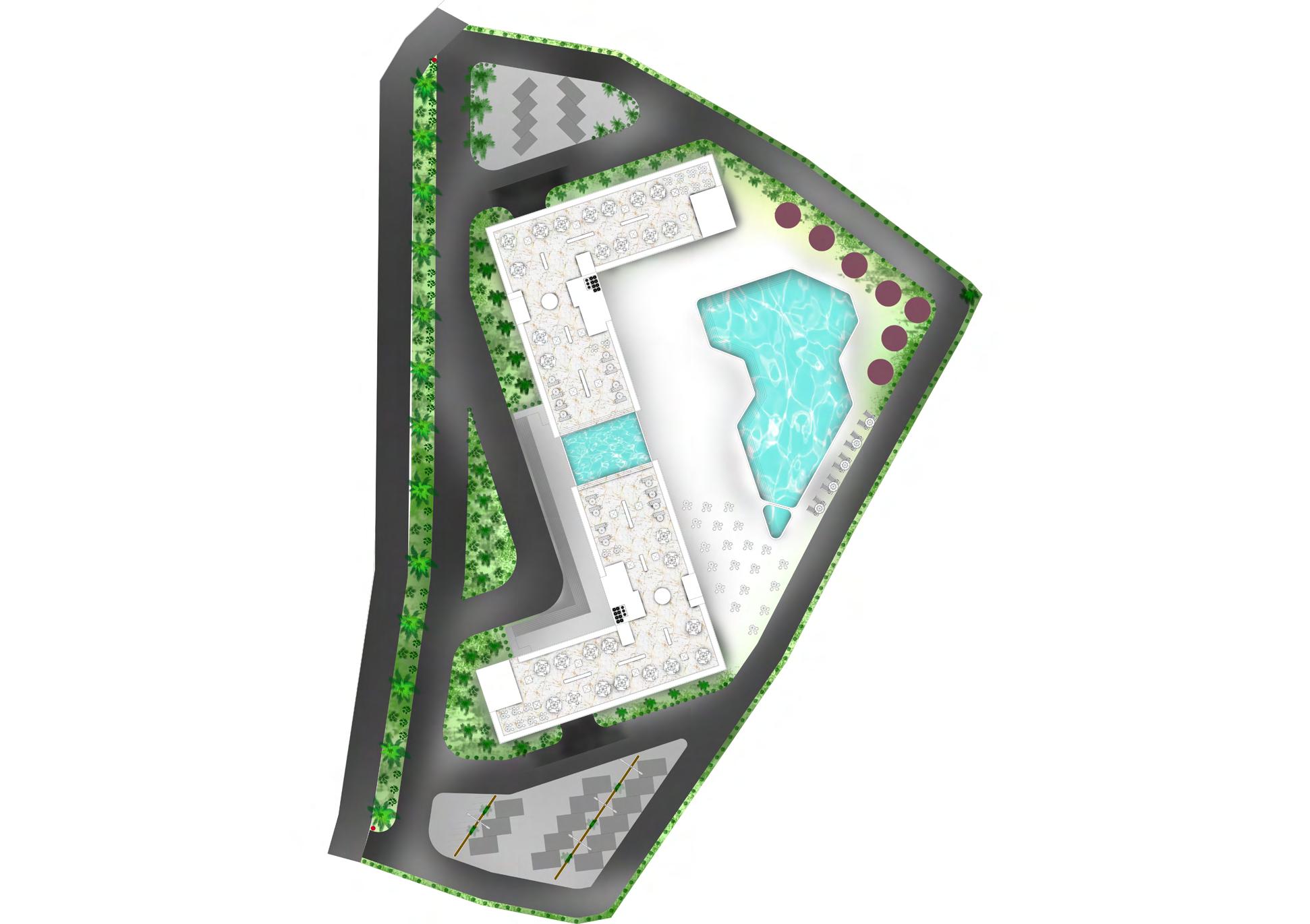

Concept, Site Plan o6 Site Plan Site is located at Ashwem, Mandrem, Goa (15°38’59.7”N 73°43’04.7”E). Site area is about 10916.54sq.m, there is a 5 meters Wide road.
STAGE 2
STAGE 3


Ground Floor Plan :
1. Waiting Area- 485 sq m
2. Chairman office- 18 sq m
3. Toilets- 27 sq m
4. Cloakroom- 11 sq m
5. Electrical room- 2.8x2 sq m
6. Fire duct- 1.6x2 sq m
7. Service lift- 4x2 sq m
8. Public Lift- 4x4 sq m
9. Banquet hall 1- 155 sq m
10. Banquet hall 2- 314 sq m
11. Toilets- 46 sq m
12. Dining hall- 250 sq m
13. Kitchen- 107 sq m
14. Store room- 17 sq m
15. Cold storage- 14 sq m
16. Toilets- 22.8 sq m
Ground Floor Total Area=1500 sq m
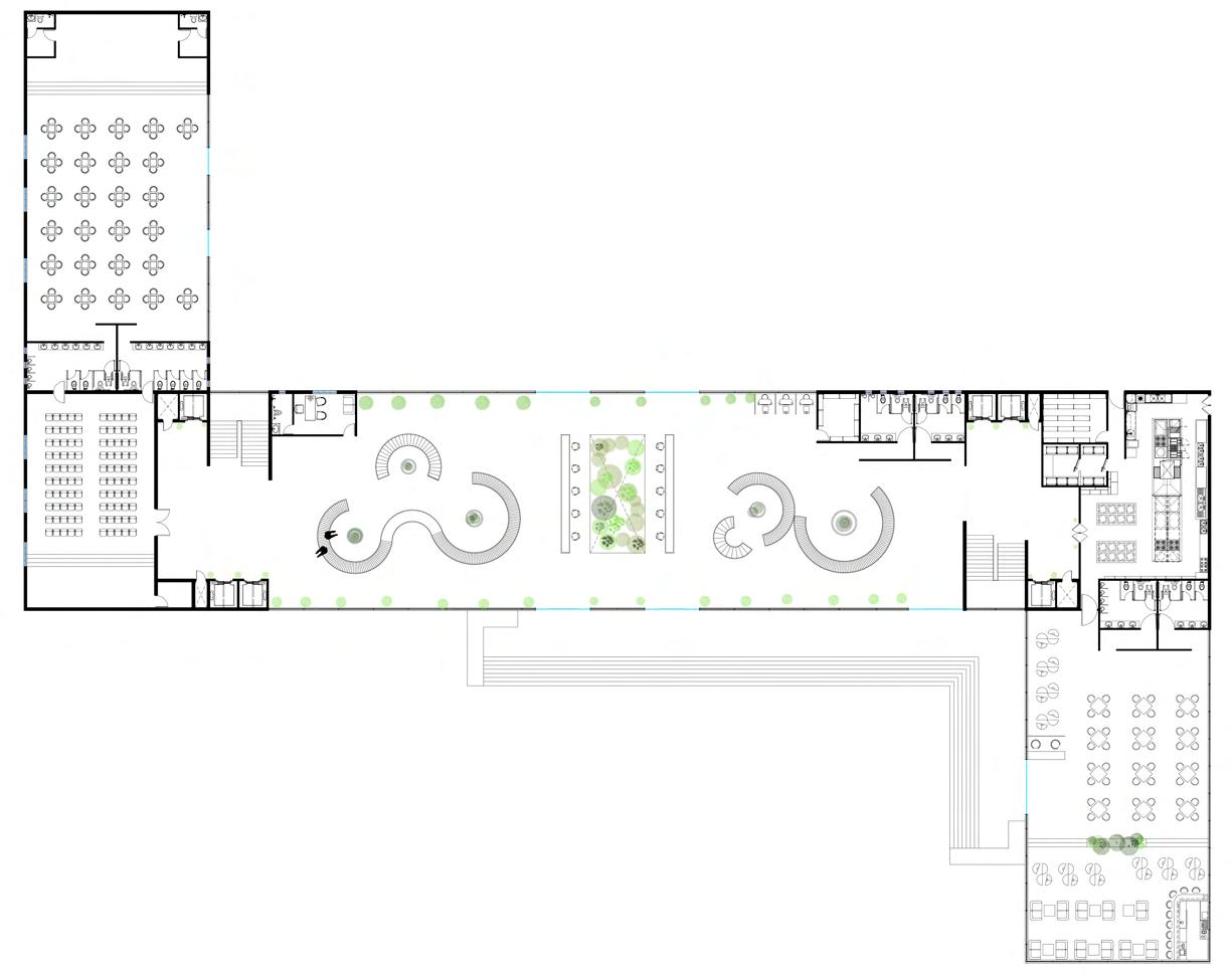

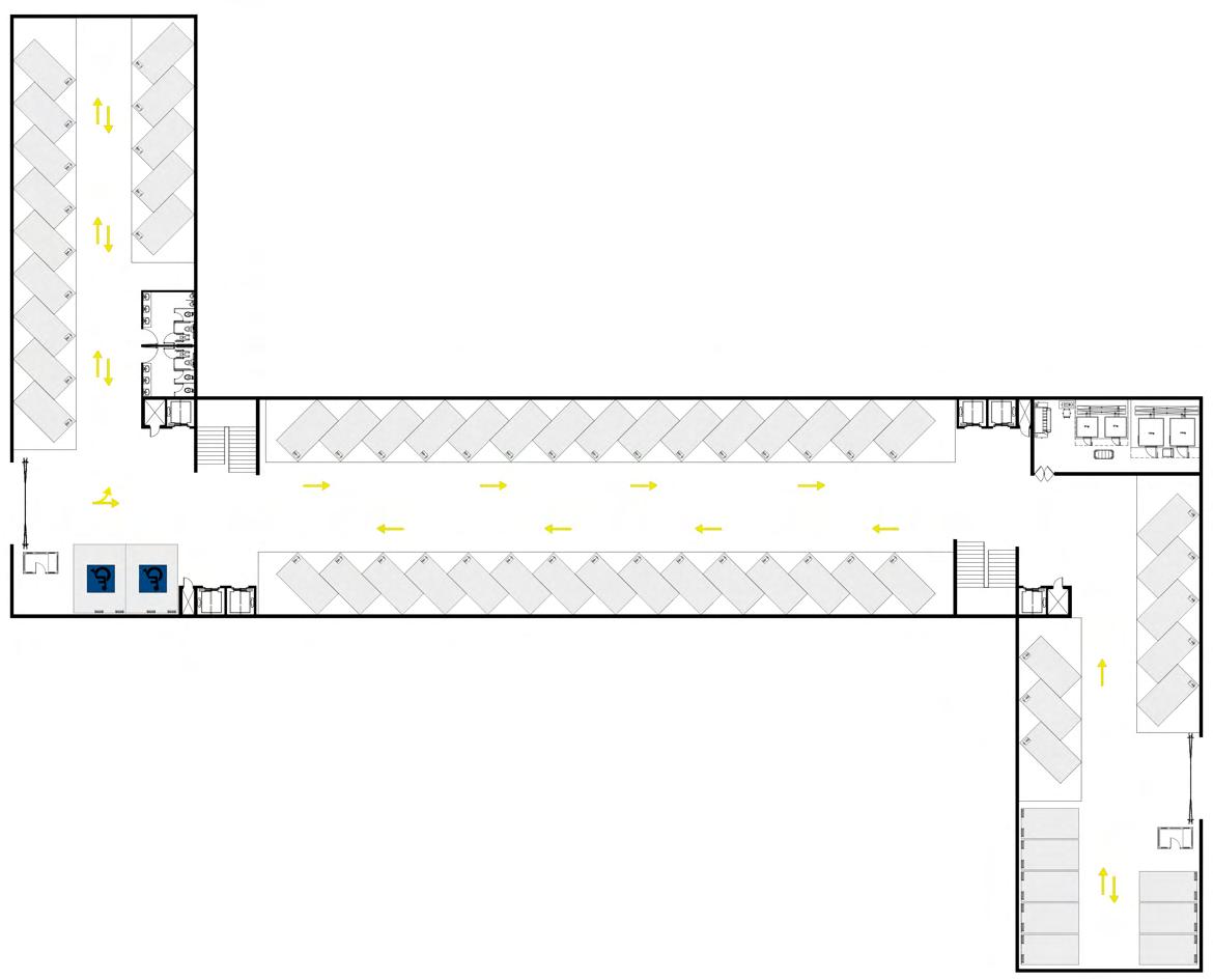
Hotel Floor Plan 07
First Floor Plan : 1. Waiting Area- 27.7 sq m 2. Gym area- 207.7 sq m 3. Changing room- 9.7x2 sq m 4. Spa- 220 sq m 5. Office space- 122 sq m 6. Discussion room- 82 sq m 7. Fire duct- 1.6x2 sq m 8. Electrical room- 2.8x2 sq m 9. Service lift- 4x2 sq m 10. Public Lift- 4x4 sq m First Floor Total Area=711.6 sq m 10 11 10 7 10 10 14 15 13 16 16 12 11 11 9 9 1 3 3 2 4 8 6 5 7 2 1 1 4 3 3 8 7 5 8 6 5 7 8 8 6 A A A’ A’ B B B’ B’ First Floor Plan
Ground Floor Plan

3-5 Floor Plan :
Hotel Floor Plan, Types Of Rooms 08
1. Public Lift- 4x4 sq m 2. Fire duct- 1.6x2 sq m 3. Service lift- 4x2 sq m 4. Electrical room- 2.8x2 sq m 5. Single bedroom- 17X18 sq m 6. Double bedroom- 27X12 sq m
Suite room 1- 52.5X4 sq m 8. Suite room 2- 50 X4 sq m 9. Suite room 3- 57X2 sq m TOTAL ROOMS- 40X3= 120 ROOMS 10. Launge area - 7.2X2 sq m 11. Launge area - 14X2 sq m 1. SINGLE BEDROOM 18X3=54 ROOMS 2. DOUBLE BEDROOM 12X3=36 ROOMS 3. SUITE ROOM 2 4X3=12 ROOMS 4. SUITE ROOM 3 2X3=6 ROOMS 5. SUITE ROOM 1 4X3=12 ROOMS 9 5 5 4 3 6 6 6 1 1 2 10 6 6 8 8 6 5 5 5 5 5 5 5 7 7 7 7 5 5 5 5 11 10 5 5 5 5 4 3 6 6 6 6 6 6 8 8 5 9 1 1 A A’ B B’
7.

Basement Floor Plan :
1. Public Lift- 4x4 sq m
2. Fire duct- 1.6x2 sq m
3. Service lift- 4x2 sq m
Basement Floor Plan
Terrace Floor Plan :
1. Public Lift- 4x4 sq m
5. Bar - 19.8x2 sq m
2. Fire duct- 1.6x2 sq m
3. Service lift- 4x2 sq m
4. Electrical room- 2.8x2 sq m
6. Toilet - 13.5x2 sq m
7. Pool - 126 sq m
Hotel Floor Plan 09
4. Electrical room- 2.8x2 sq m 5. Laundry room- 64.2 sq m 6. Toilet- 13.5x2 sq m
A A A’ A’ B B B’ B’ 6 6 4 4 5 2 2 1 1 1 1 3 6 6 6 4 4 2 2 1 1 1 1 5 5 7 Terrace Floor Plan 3 3 6 3

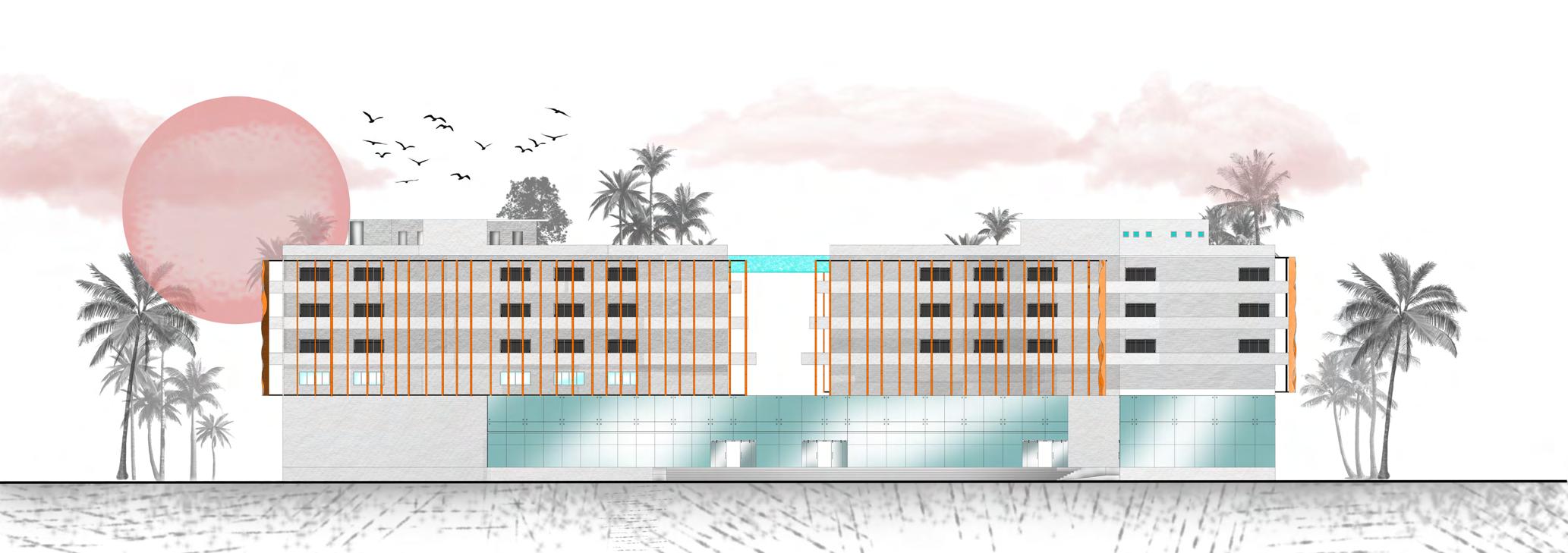
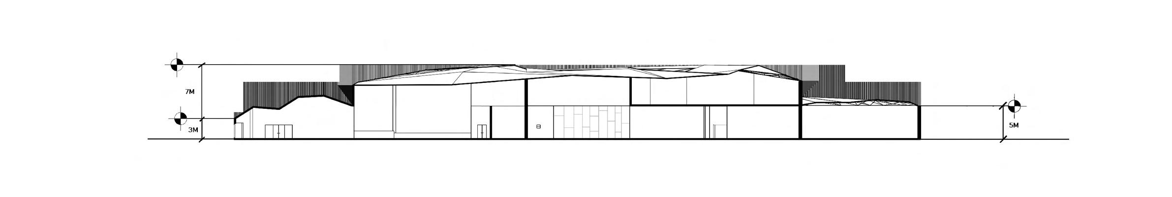
FRONT ELEVATION
Hotel Elevations 10
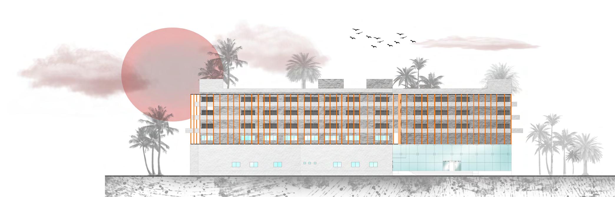
SOUTH ELEVATION G G L L
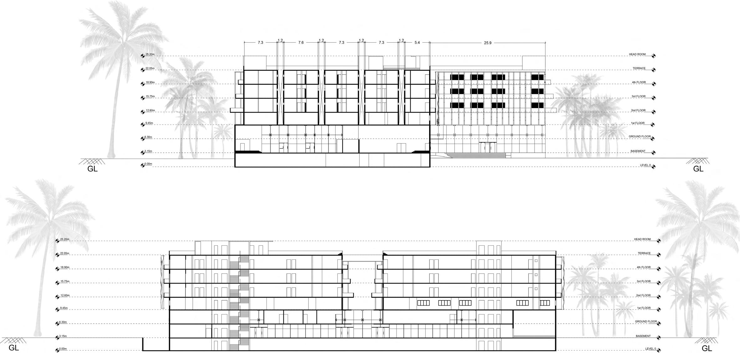
Hotel Sections 11
SECTION @ BB’
SECTION
@ AA’
Render Images 12 Hotel Renders
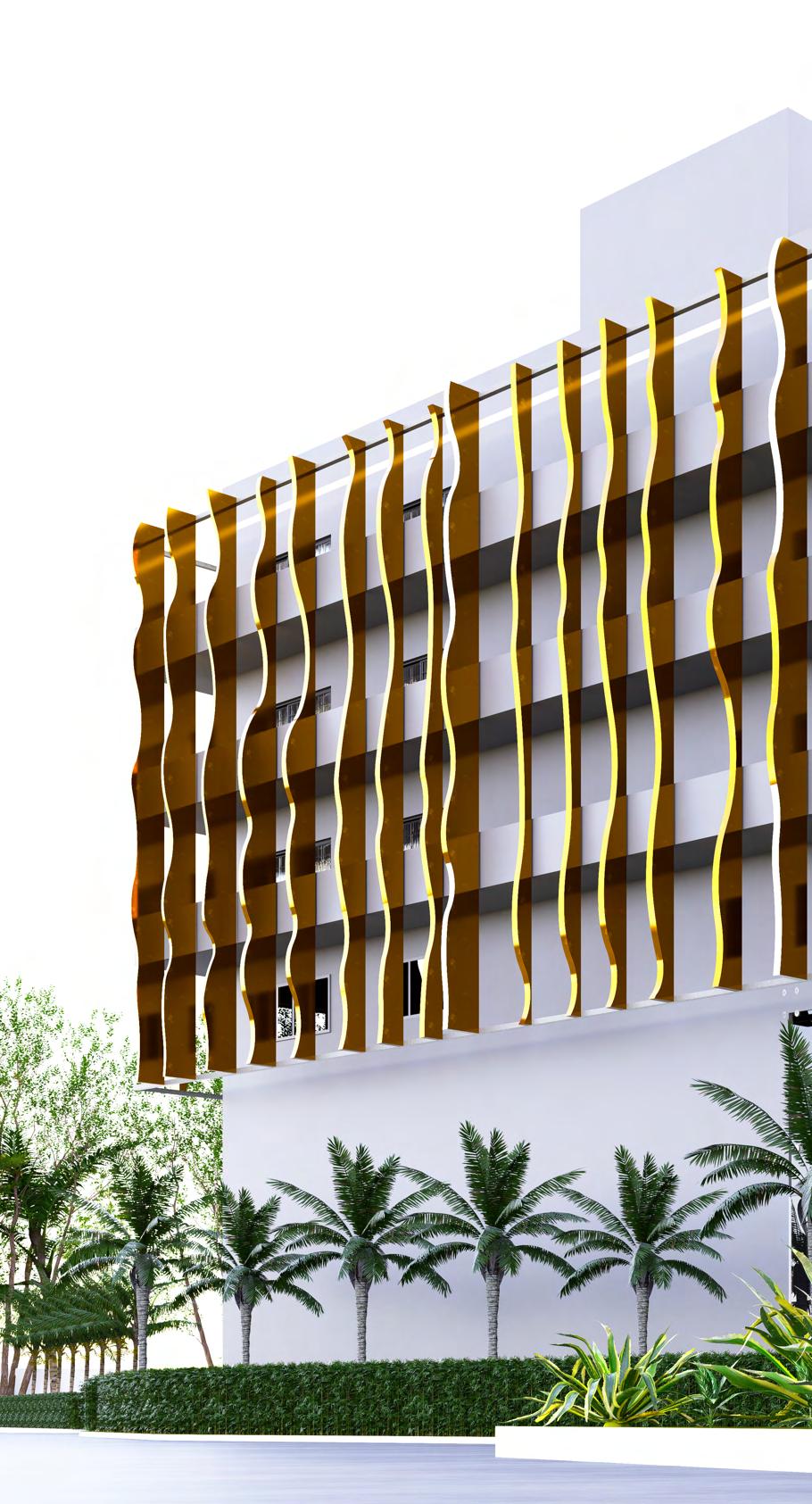
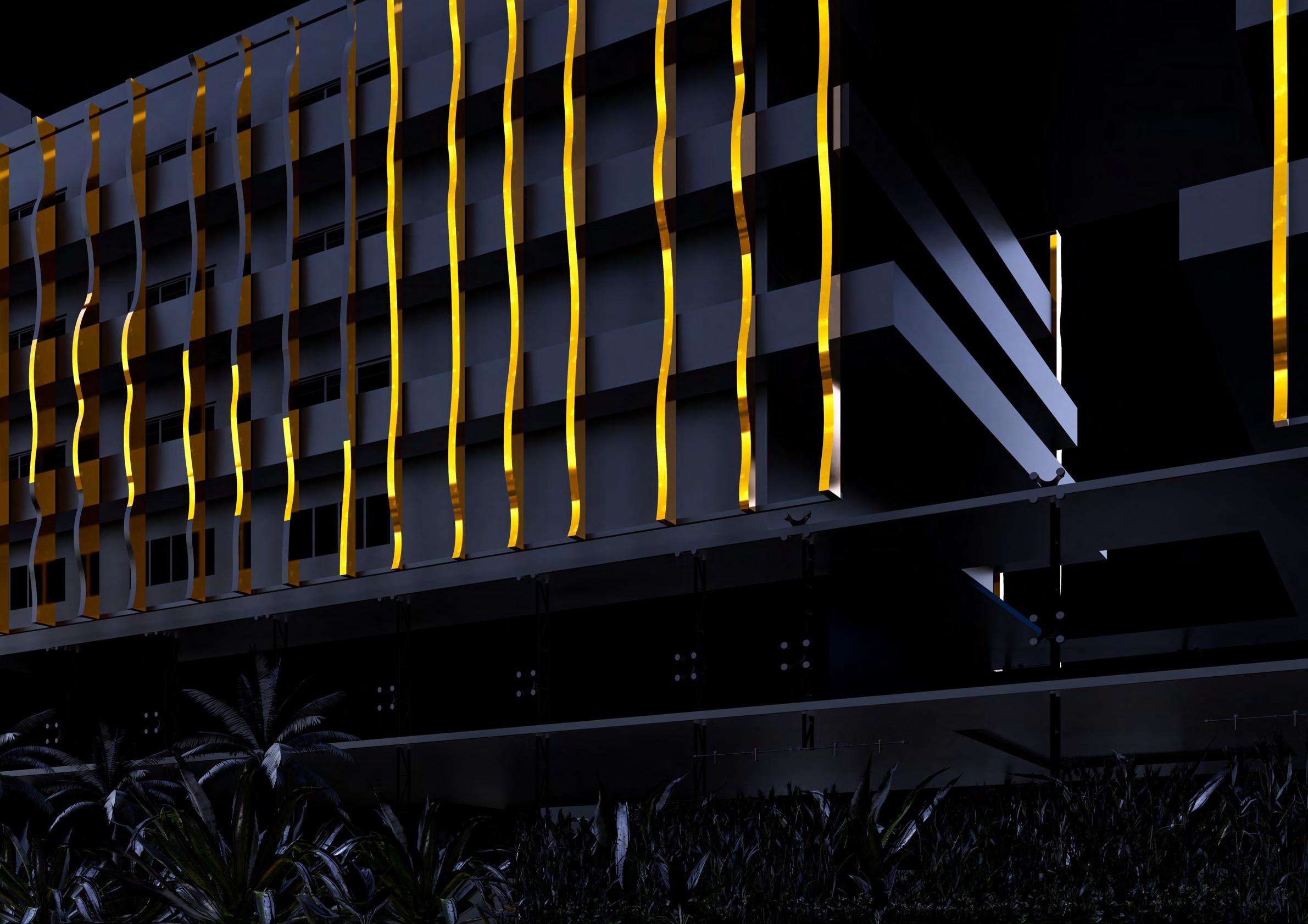
Dynamic Facade
Hotel facade that incorporates adaptive or dynamic facade design.
A dynamic facade is a skin that has evolved over time with the help of engineered solutions; its purpose is to assist in the progression of Sustainable and Responsive architecture.
Dynamic facades act as filters between the indoors and the outside, facilitating the users by providing shade, sunlight, ventilation and a visual union with the moving world outside. This idea isn’t new, but architects have only recently started incorporating it into their designs and structures.
hrough fully integrated design strategies, today’s facade can provide responsive and per-formative envelopes that both contextually and conceptually react to their local surroundings, whilst simultaneously determining interior conditions
In modern facade design, fins made from advanced materials are commonly used. These fins are strategically arranged to block direct sunlight, thereby reducing heat gain and improving the comfort of the building’s occupants. Additionally, the design of the fins also takes into consideration the flow of wind, allowing for good natural ventilation. By incorporating these features, modern facade design can help create more comfortable and sustainable buildings.

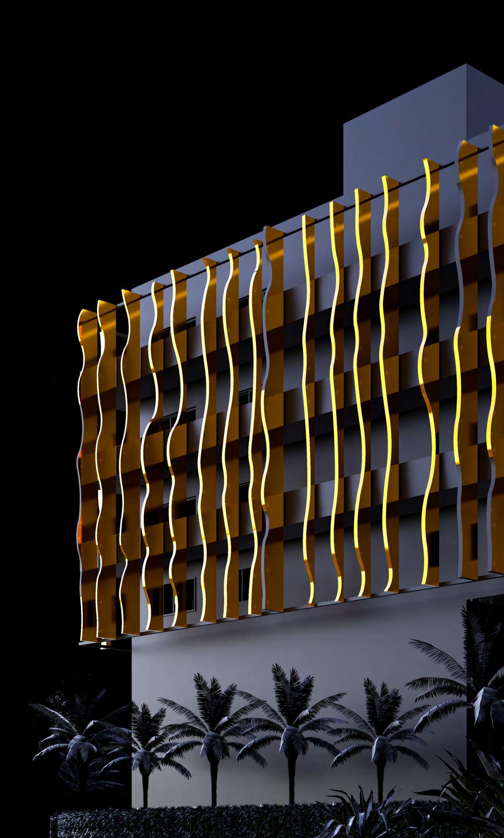
Hotel’s Dynamic Facade 13

03
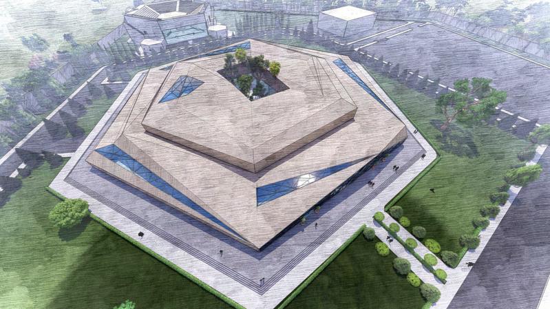
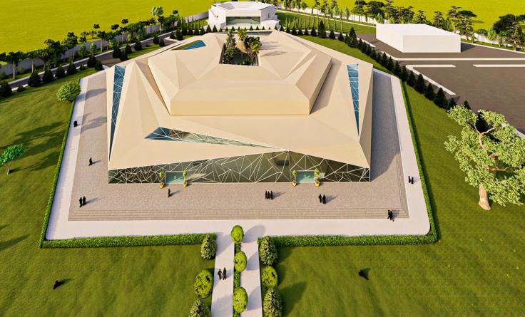
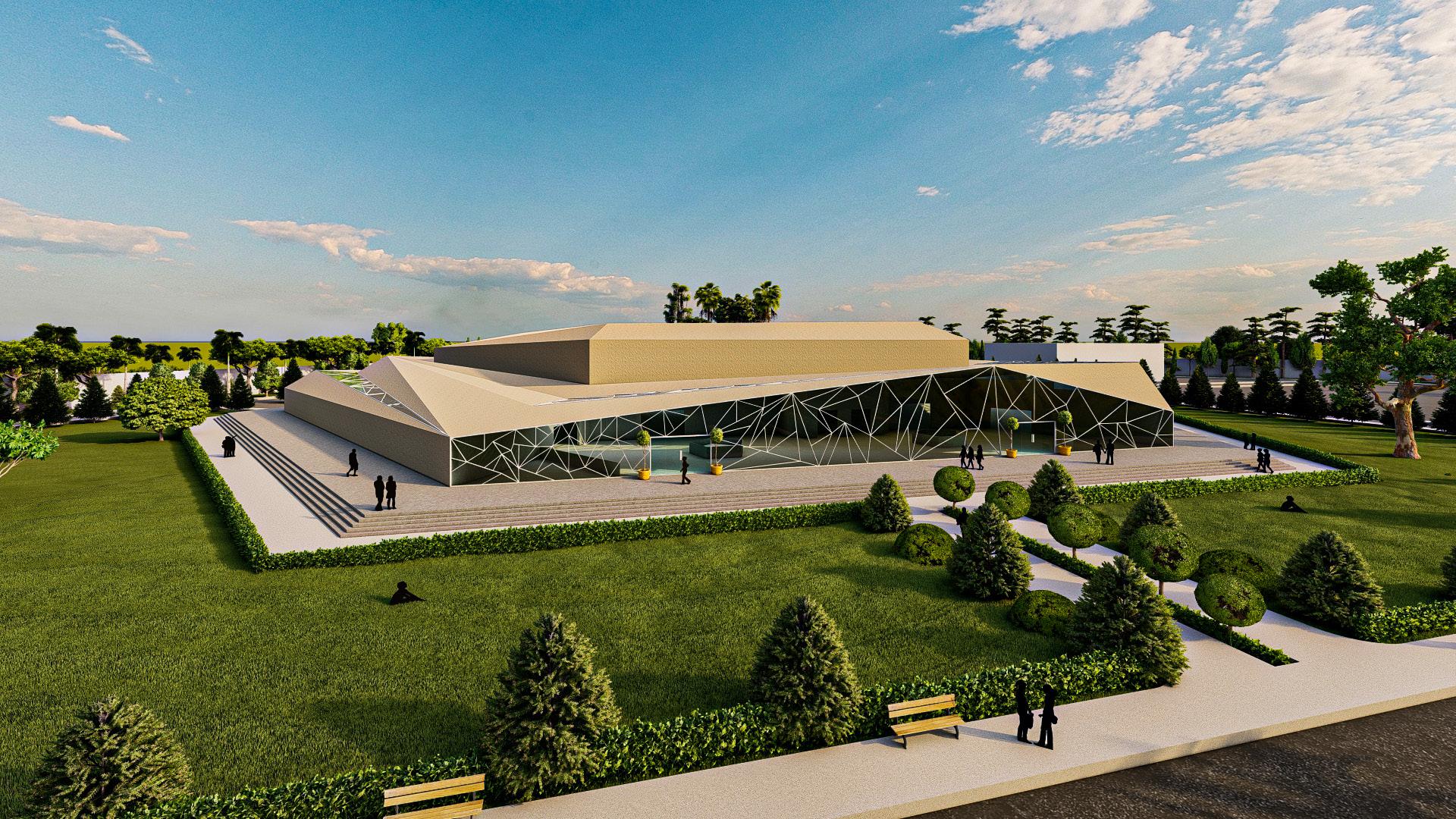
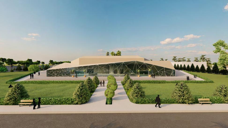
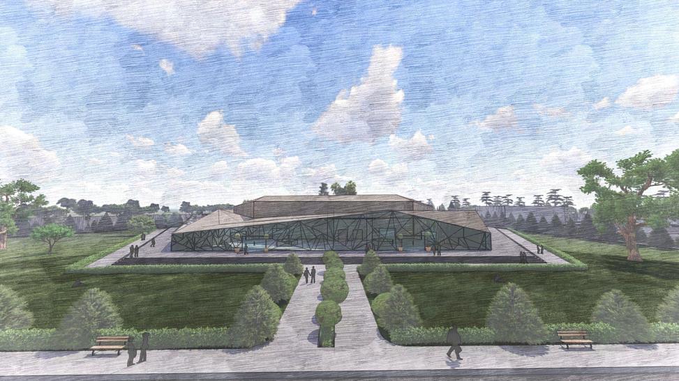
Art Gallery
Academic project I Semester 05 I 2021
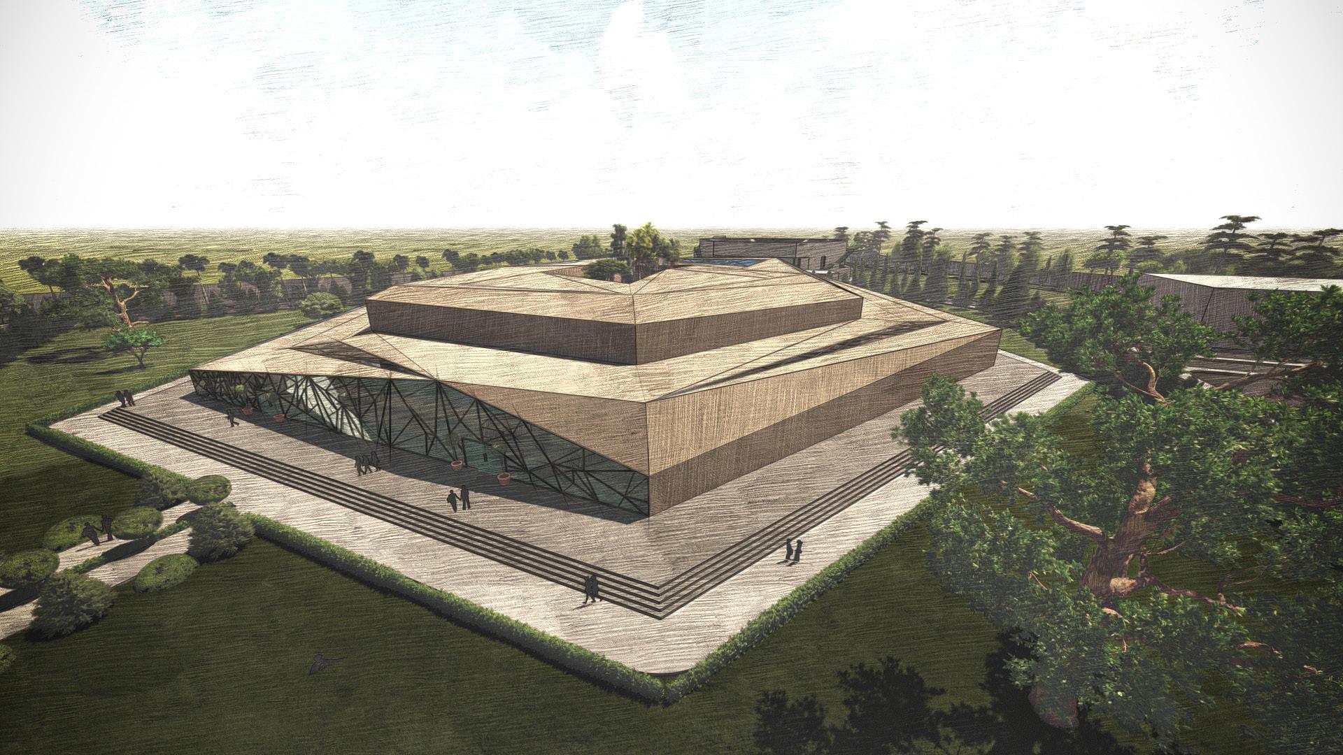
The art gallery project near Tumkur covers an area of 58422 sq m and aims to attract people. To achieve this, the building has a unique facade with a folded roof that changes its appearance as the sun moves. This design not only adds to the building’s aesthetic appeal but also makes use of natural light and promotes sustainability. The project showcases an innovative and environmentally conscious approach to architecture, creating a space that is both visually appealing and functional.
 Autocad I Sketchup I Lumion I Photoshop I Illustrator
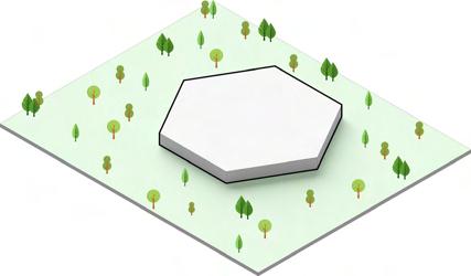
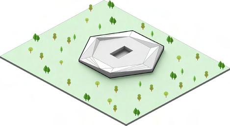
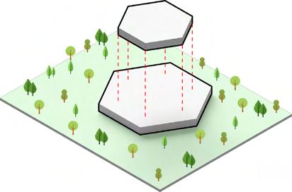
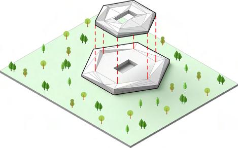
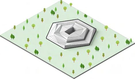
Concept & Design Form :
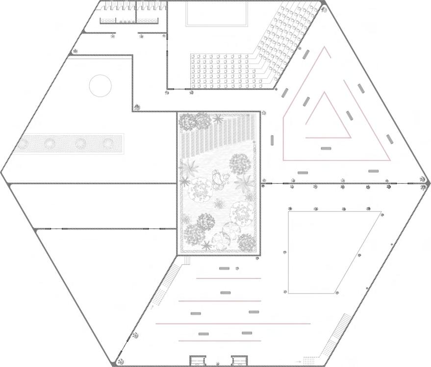
The Art Gallery Concept “FORM FOLLOW FUNCTION” emphasizes the importance of the relationship between form and function in architecture and design. This project applies the principle to create an art gallery out of a hexagon-shaped diamond, which provides an attractive exterior and six distinct zones of space. The folded roof format creates an innovative design that enhances the building’s aesthetic appeal while preventing direct sunlight from damaging artwork. Several openings are provided at the top to maximize daylight utilization throughout the building space without negatively affecting the artwork. The combination of the folded roof format and strategically placed openings provides functional benefits and enhances the building’s visual effect. Overall, the project is an excellent example of the “FORM FOLLOW FUNCTION” principle in action, creating a unique and attractive space for displaying artwork.


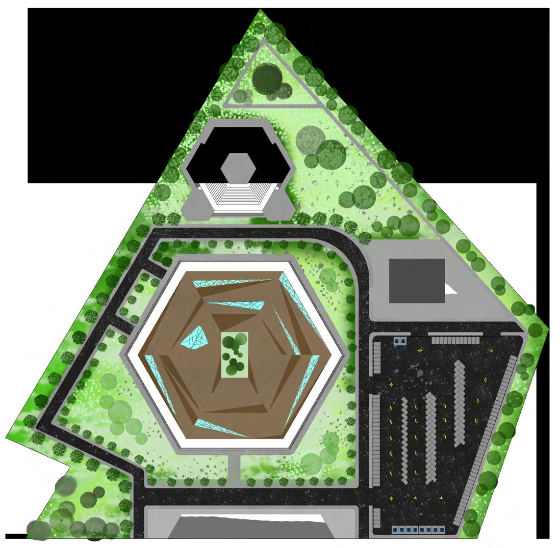
Concept, Site Plan 16
Site Plan
Site is located beside Sri Sidhartha Medical college, opposite to Bharath Petrol Pump-N S Fuelling Dervices,Hanumanthapura, Near Heggere, Tumkuru, Karnataka 572107. Site area is about 58422 sq.m

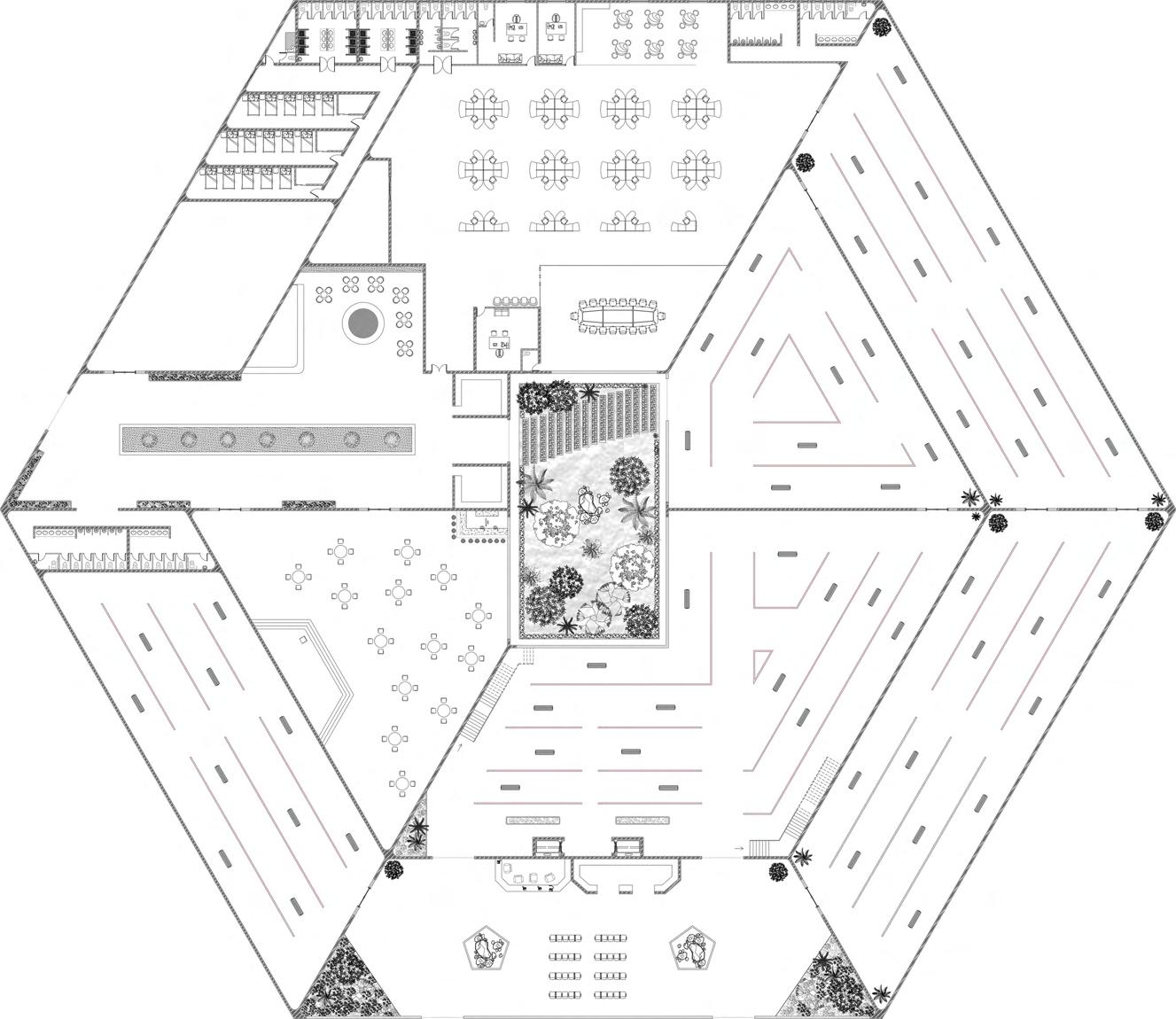

Ground Floor Plan :
1. Waiting Area-86 sq m
2. Exhibition Space-3625 sq m
3. Office-1018 sq m
4. Conference room- 149 sq m
5. Pantry- 84 sq m
6. Toilets- 32 sq m
7. Store Room- 232 sq m
8. Toilets- 97+71 sq m
9. Dormitories-124 sq m
10. Auction Hall-574 sq m
11. Store-20x2=40 sq m
12. Food Court-140 sq m
Ground Floor Total Area=8158 sq m
Toilets- 76 sq m
Conservation Laboratory-573 sq m First Floor Total Area=3915 sq m
Ground Floor Plan First Floor Plan Art Gallery Floor Plan 17 A A’ A A’ 7 9 4 4 4 10 11 11 12 8 8 1 1 1 2 2 2 2 2 2 6 5 3 3
First Floor Plan : 1.Exhibition Space-1161 sq m 2.Workshop-367 sq m 3.Common
4.
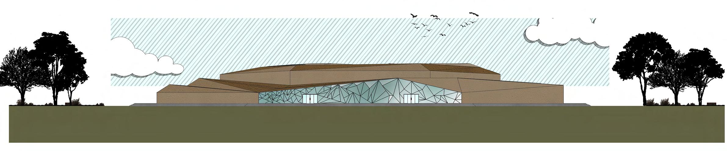
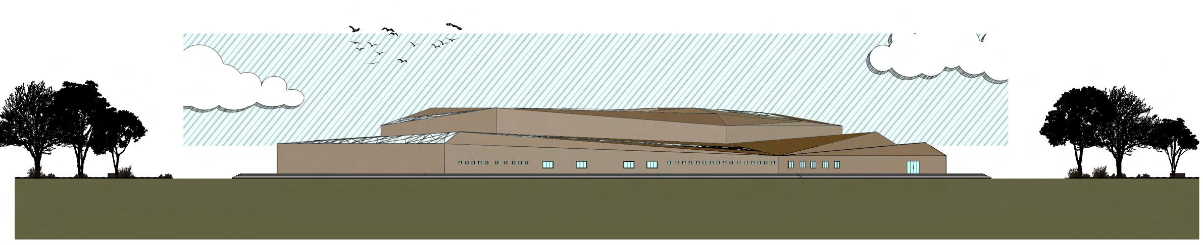
Art Gallery’s Elevations & Section 18
FRONT ELEVATION
SECTION @ AA’
BACK ELEVATION
Art Gallery Renders
Art Gallery Renders Render Images 20
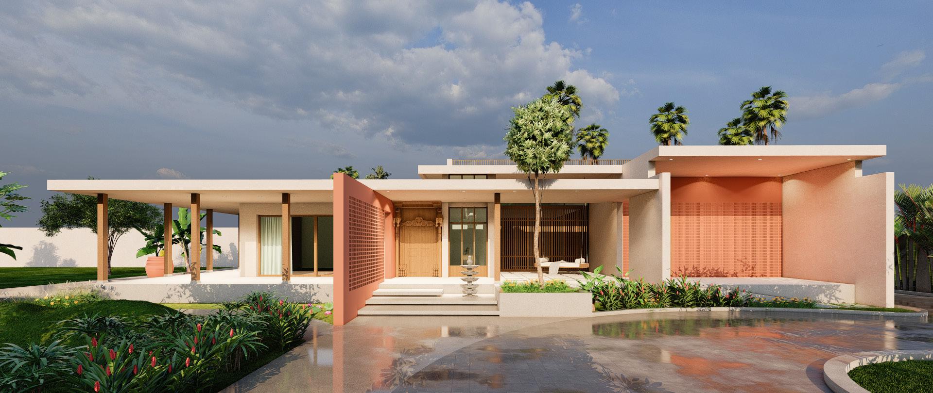
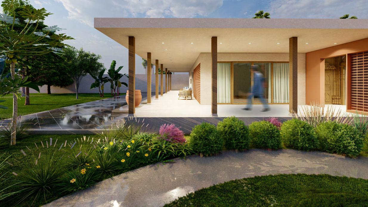
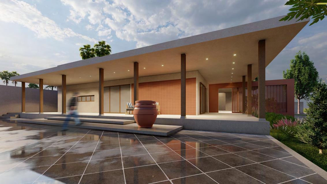
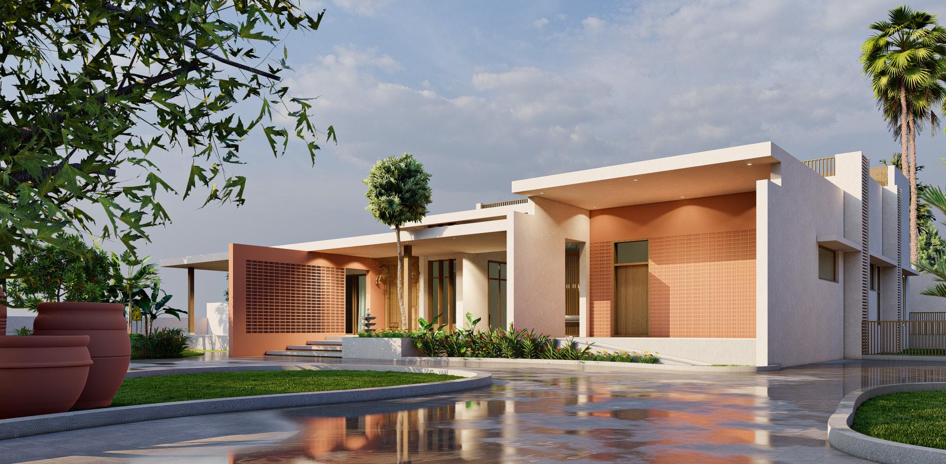
Sketches 28 Janwada Farm House 21
04
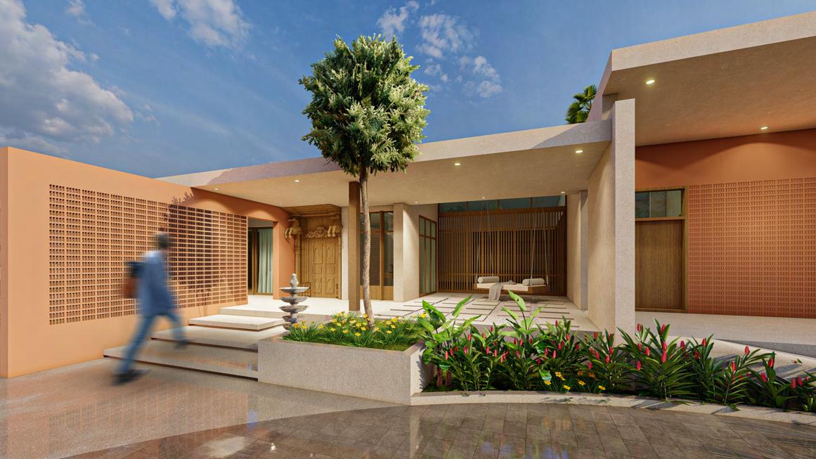
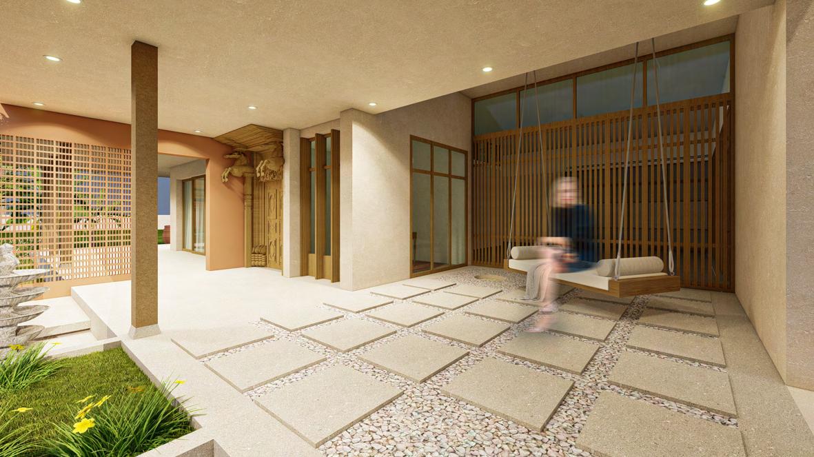
Janwada Farm House
Internship project I Semester 10 I 2024
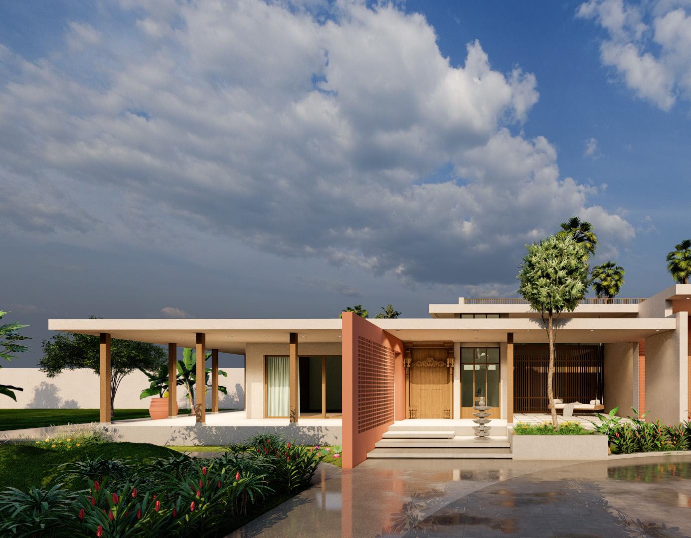
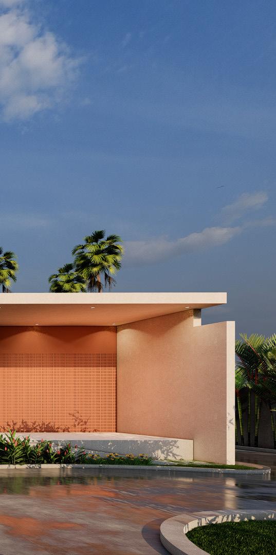
Nestled amidst the serene landscape of Janwada, Hyderabad, a sprawling farmhouse project unfolds across 35,167 sq ft, with 5,064 sq ft thoughtfully designated for the residence. This haven is envisioned as a sanctuary for family retreats, offering an escape where cherished moments are shared and memories are made.
Architectural ingenuity takes precedence, with therm walls strategically employed to mitigate heat gain and ensure year-round comfort. Leveraging the natural topography, variations in roof levels invite ample natural light into the living spaces, fostering a bright and inviting atmosphere. Complementing the design, natural ventilation techniques are seamlessly integrated, promoting airflow and enhancing indoor comfort.
Beyond functionality, sustainability is a key focus. The landscape design harmonizes with the surroundings, enhancing the overall aesthetic appeal while fostering a deep connection with nature. In essence, this farmhouse project represents a harmonious blend of modern living and environmental consciousness, offering a tranquil retreat where families can gather to unwind and reconnect with each other amidst the beauty of nature.
Autocad I Sketchup I Lumion I Photoshop
Janwada Farm House 22
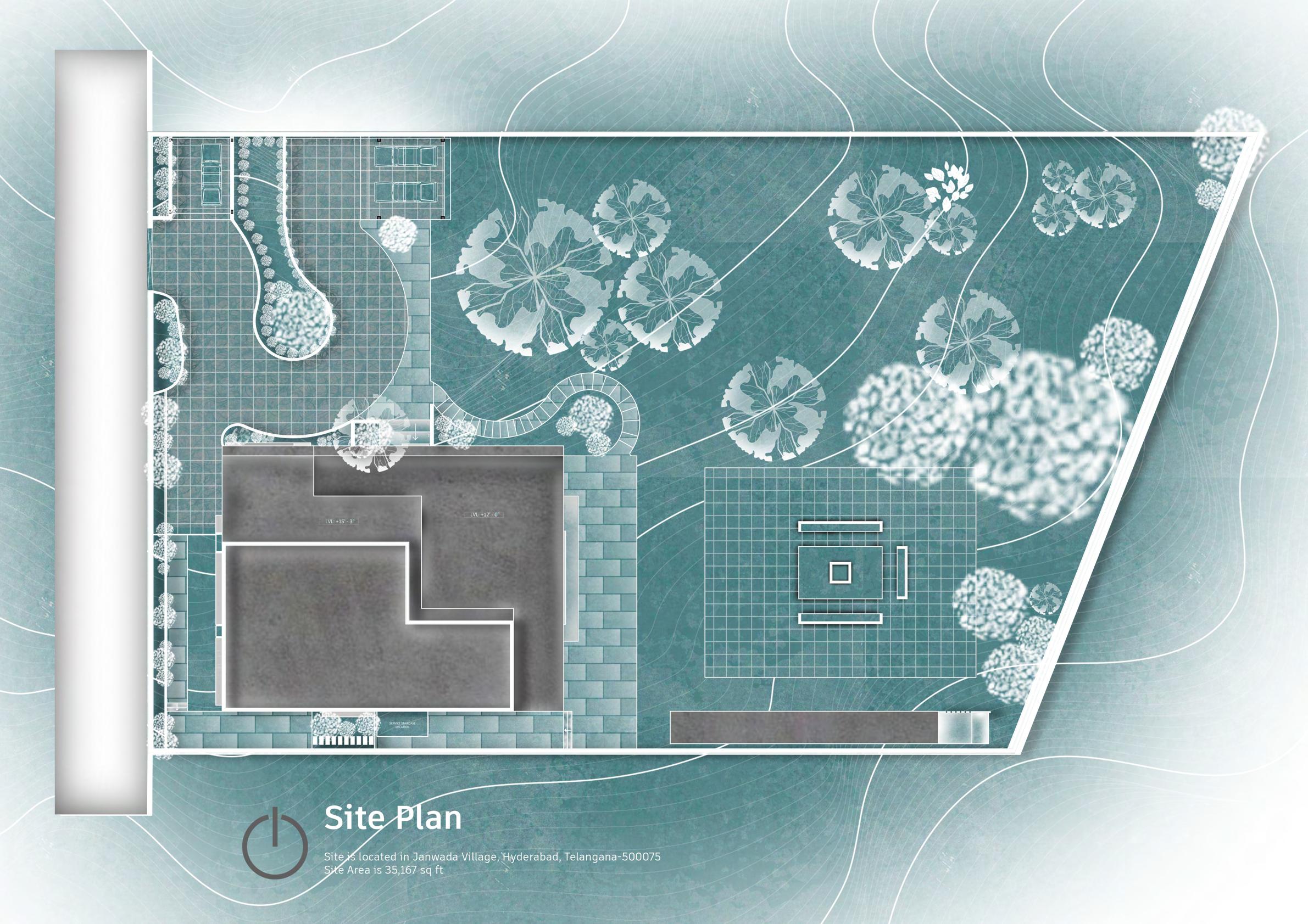
Site Plan 23
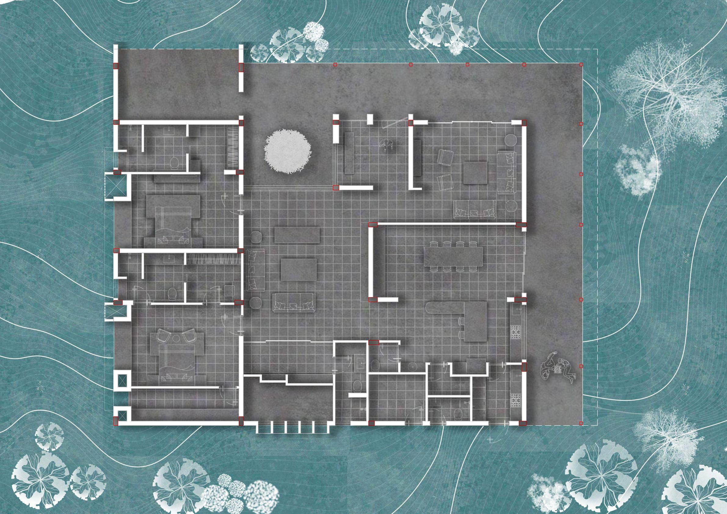

1. Foyer - 128 sq ft 2. Courtyard - 167 sq ft 3. Drawing room - 303 sq ft 4. Living room - 538 sq ft 5. Dining - 307 sq ft 6. Kitchen - 262 sq ft 7. Powder room - 24 sq ft 8. Utility room - 73 sq ft 9. Store room - 30 sq ft 10. Servent toilet - 28 sq ft 11. Servent room - 75 sq ft 12. Master Bedroom - 274 sq ft 13. M. toilet+Dress - 168 sq ft 14. Walk in Closet - 100 sq ft 15. Kids Bedroom - 200 sq ft 16. Kids toilet+Dress - 67 sq ft 17. Guest Bedroom - 250 sq ft 18. G. toilet+Dress - 157 sq ft 12 14 15 16 11 7 9 10 8 6 5 3 1 4 13 18 18 7 2 13 17 Floor plan 24
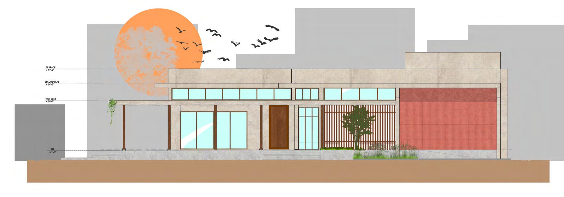
FRONT ELEVATION
Elevation 25
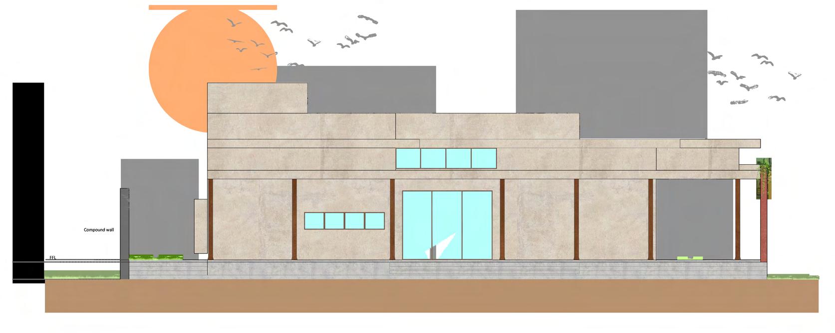
SOUTH ELEVATION
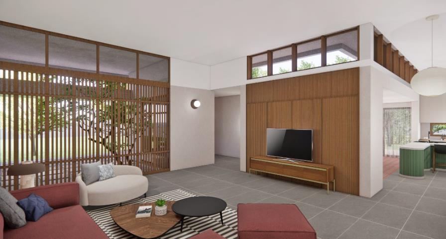
Renders 26
Renders 27
Renders 28

Working Drawing 33 Balcony area 4'8" X 6'6" UP Toilet 8'0" X 6'0" Lift 5'0" X 5'0"
Master bedroom 13'6" X 13'6" space for Storage and water purifier 11'0" X 4'0" Bedroom 02 11'0" X 12'0" FAMILY AREA 10'6" X 15'6" W/W 5'6" X 9'0" Balcony 13'2" X 6'2" AREA STATEMENT NAME OF BUILDING. AREA TOTAL PLINTH AREA -1,080.00 Sq 3,450.00 Sq COVERAGE -TOTAL PLINTH AREA SITE AREA 100 1,080 X 100 1,200 90.00% FAR TOTAL BUILT UP AREA 3,450 = 2.875 > 2.00 TOTAL SITE AREA 1,200.00 Sq TOTAL BUILT UP AREA SITE AREA 1,200 1080.00 Sq TOTAL 210.00 Sq 3,450.00 Sq SCHEDULE OF OPENING TYPEDESCRIPTION SIZE LINTEL D2 TOILET DOOR D1ROOM DOOR GARAGE DOOR MDMAIN DOOR 3'-6"X7'-0" 7'-0" 3'-0"X7'-0" 7'-0" 2'-6"X7'-0" 7'-0" 2'-0"X7'-0" 7'-0" GENERAL NOTES: 1.All Dimension are in feet/inches and are unfinished dimensions unless otherwise specified 2. Do not scale the drawings only written dimensions shall be followed any discrepancies noted shall be brought to the consultant prior to execution. 3. This drawings should be read in conjunction with other relevant floor plan drawings PROJECT: 01 1,080.00 Sq 1080.00 Sq DATE SCALE T S Designed By Project ID :RB-10-DP REVISION DRAWING TITLE GROUND FLOOR PLAN Rev NoDate Remark 02 D3 Toilet 7'0" X 9'0" Window 5'6"x4'6"(window top at beam Ventilator 1'6"x1'6" bottom level) Toilet ventilator will starts from bottom of beam Ventilator 1'6"x1'6" Toilet ventilator will starts from bottom of beam Window 4'6"x4'0" Sill = 3'0" Bay Window Window 2'6"x4'0" Sill = 3'0" Window 2'6"x4'0" Sill = 3'0" Window 2'6"x4'0" Sill = 3'0" Window 2'6"x6'0" Sill = 1'0" Window 3'0"x4'0" Sill = 3'0" WORKING DRAWING sliding fxd fxd GROUND FLOOR FIRST FLOOR SECOND FLOOR TERRACE FLOOR
Utility area 13'2" X 5'2" Garage 13'0" X 16'0" Foyer Verandah 8'0" X 4'6" 6'0" X 7'6" UP Lift 5'0" X 5'0" Living & Dining 13'6" X 24'0" Island Kitchen 10'8" X 17'6" P. toilet 3'2" x 5'0" A B C A B C 1 2 3 4 1 2 3 4 2'-3" 11'-4" 14'-2" 2'-3" 2'-3" 14'-0" 16'-0" 5'-6" 2'-3" 2'-0" 11'-4" 14'-2" 2'-3" 2'-3" 14'-0" 16'-0" 5'-6" 2'-3" 3" Window 4'0"x4'0" Sill = 3'0" Window 6'0"x4'0" Sill = 3'0" Ventilator 2'0"x2'0" SILL 5'0" Window 6'0" NOTE: refer staircase detail drawing Window 4'0"x4'0" Sill = 3'0" Window 6'0"x4'0" Sill = 3'0" FIRST FLOOR PLAN AREA STATEMENT NAME OF BUILDING. TOTAL PLINTH AREA -1,080.00 Sq 3,450.00 Sq COVERAGE -TOTAL PLINTH AREA SITE AREA 100 1,080 X 100 1,200 90.00% FAR TOTAL BUILT UP AREA 3,450 = 2.875 2.00 TOTAL SITE AREA 1,200.00 Sq TOTAL BUILT UP AREA SITE AREA 1,200 1080.00 Sq TOTAL 210.00 Sq 3,450.00 Sq SCHEDULE OF OPENING TYPEDESCRIPTION SIZE LINTEL D2 TOILET DOOR D1 ROOM DOOR GARAGE DOOR MDMAIN DOOR3'-6"X7'-0" 7'-0" 3'-0"X7'-0" 7'-0" 2'-6"X7'-0" 7'-0" 2'-0"X7'-0" 7'-0" GENERAL NOTES: 1. All Dimension are in feet/inches and are unfinished dimensions unless otherwise specified 2. Do not scale the drawings only written dimensions shall be followed any discrepancies noted shall be brought to the consultant prior to execution. 3. This drawings should be read in conjunction with other relevant floor plan drawings PROJECT: 01 1,080.00 Sq 1080.00 Sq DATE SCALE T S Designed By Project ID :RB-10-DP REVISION DRAWING TITLE SECOND FLOOR PLAN Rev NoDate Remark 02 D3 WORKING DRAWING GROUND FLOOR FIRST FLOOR SECOND FLOOR TERRACE FLOOR TERRACE FLOOR PLAN Lift 5'0" X 5'0" FAMILY AREA 10'6" X 11'4" ROAD Bedroom 03 13'6" X 12'2" Balcony 13'2" X 5'2" Store room with water purifier 11'0" X 4'6" Media room 11'0" X 10'6" UP Toilet 7'8" X 5'0" Toilet 10'2" X 5'0" Bedroom 04 11'0" X 12'0" Window 3'0"x4'0" Sill = 3'0" Window 3'0"x4'0" Sill = 3'0" Window 2'6"x4'0" Sill = 3'0" Ventilator 2'0"x2'0" Toilet ventilator will starts from bottom of beam Ventilator 2'0"x2'0" Toilet ventilator will starts from bottom of beam Window 5'6"x4'6"(window top at beam bottom level) Bay Window Bay Window Window 2'6"x4'0" Sill = 3'0" sliding fxd fxd sliding fxd fxd Lift 5'0" X 5'0" ROAD DN Slab line Slab line Space for inverter Staircase Headroom OPEN TERRACE Space for OHT
ROAD
ROAD
Working Drawing 34 SLIDING GATE 18' WIDE LANDSCAPE UP UP UP SUMP CLIENT DRWNG TITLE GROUND FLOOR PLAN DRAWN: DEALT/CHKD: HR DATE: SCALE: NTS PURPOSE: REV No DESCRIPTION FOR REVISIONS CLIENT DRWNG TITLE FIRST FLOOR PLAN DRAWN: DEALT/CHKD: HR DATE: SCALE: NTS PURPOSE: REV No DESCRIPTION FOR REVISIONS CLIENT DRWNG TITLE SECOND FLOOR PLAN DRAWN: DEALT/CHKD: HR DATE: SCALE: NTS PURPOSE: REV No DESCRIPTION FOR REVISIONS UP DWN ±0'0" +0'6" +0'6" 5' HEIGHT WALL +11'6" +23'0" +11'0" +11'0" CLIENT DRWNG TITLE THIRD FLOOR PLAN DRAWN: DEALT/CHKD: HR DATE: SCALE: NTS PURPOSE: DESCRIPTION FOR REVISIONS UP DWN +34'6" CLIENT DRWNG TITLE TERRACE FLOOR PLAN DRAWN: DEALT/CHKD: HR DATE: SCALE: NTS PURPOSE: DESCRIPTION FOR REVISIONS UP DWN +45'0" +44'6" +44'6" HAMMOCK B2(9" X 18") B3(9" 18") B4(9" 18") B5(9" X 18") B7(9" 24") B9(9" X 18") B10(9" 18") B11(9" 18") B12(9" 18") B13(9" 18") B15(9" X 18") B16(9" X 18") B17(9" X 18") B18(9" X 18") B19(9" X 18") B21(9" X 18") B22(9" X 18") B23(9" X 18") B24(9" X 18") B27(9" X 18") B28(9" X 18") B29(9" X 18") SCALE N.T.S DRAWN CHECKED DESIGNED A4 SIZE R0 DATE: 17-03-2021 JOB TITLE PROJECT: REV.NO DATE DESCRIPTION R0 FOR DISCUSSION STATUS FOR APPROVAL THIRD FLOOR BEAM LAYOUT ARCHITECT: SUNKEN SLAB SUNKEN SLAB TOILET 6'X10' KITCHEN 10'X10'
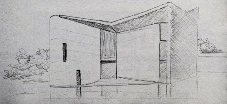
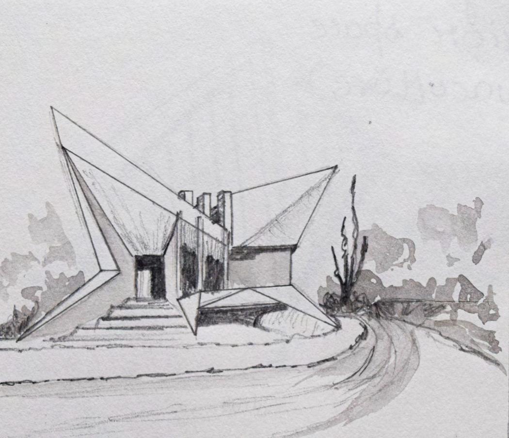
Sketches 35
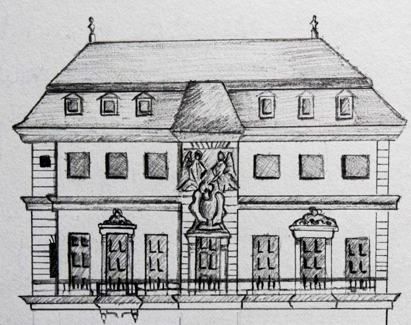

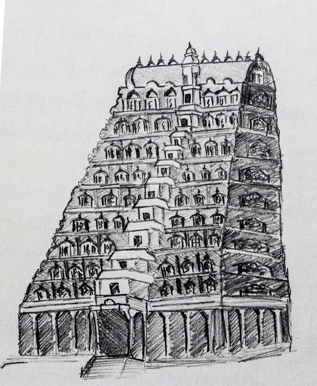
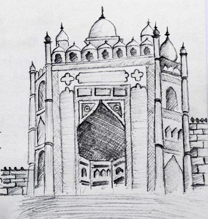
Sketches 36
Thank you Contact : +91 7022101157, 8431327476 ashuak0404@gmail.com
