Architecture Portfolio


2019-2023
 Ashwin Kumar T.S
+91 7022101157

ashuak0404@gmai.com
https://www.linkedin.com/in/ashwin-kumar-424a32208/ ak.__.a_s_h_u


I am Ashwin Kumar, Hello
As an architecture student, I am an organized individual who has a strong desire to learn and is a quick learner. I possess a genuine passion for designing spaces that connect people and the environment.
Since 2021, I have been working as a freelancer and have gained valuable experience in planning, conceptual design, 3D visualization, and interior design, primarily in the residential and commercial sectors. I am continually seeking out new opportunities to broaden my knowledge of architecture and become a more responsible and well-rounded architect.
My ultimate goal is to utilize my skills, abilities, and enthusiasm to work collaboratively with a team that will help me cultivate my potential as both a professional and an individual. I am eager to contribute my talents and enhance my growth in this exciting field.

Education
• B.arch
VTU / HMS School Of Architecture
Tumkur
• Pre University
Sri Chaitanya PU College
Tumkur
• High School
Sri Chaitanya Techno School
Tumkur
Workshops
• AI In Architecture

• Virtual Reality
• 3D Printing
• Augmented Reality in Architecture


• BIM in architecture
• Sustainable Built Environment


• Origami In Architecture
• GRIHA Workshop
• Gap
• Digital illustration
Languages
• English
• Kannada
• Hindi
• Telugu
• Tamil
Ashwin Kumar T.S

04/04/2001
Tumkur
Professional Experience
Worked As an Architectural Intern at Nandhi Architecture in Koratagere, Tumkur, I gained Valuable experience in the field and contributed to Various projects.
Experienced freelancer with a successful track record in residential and commercial projects. Skilled in time management, communication, and networking to deliver timely projects and collaborating effectively with clients.
Professional Skills
• Manual & Digital Sketching
• Model making
• Presentations

• Architectural Visualization
• Graphic design
• Architecture Photography
• Fast Learner
• Leadership
Academic Projects
Sem I -Bus Stop
Sem II -Pleader’s Residence
Sem III -Row House & Container House
Sem IV -Apartment Design
Sem V -Art Gallery & Plaza Design
Sem VI -Nursing Home & Nursing College
Sem VII -Hotel Design
Sem VIII -Urban Design
Software Skills
“Architecture is a language that speaks to us through space, form, and light, conveying emotions and ideas without the need for words.” - Louis Kahn
Row House
Semester 03 I 2020
Hotel
Semester 07 I 2022
CONTENTS
Art Gallery
Semester 05 I 2021
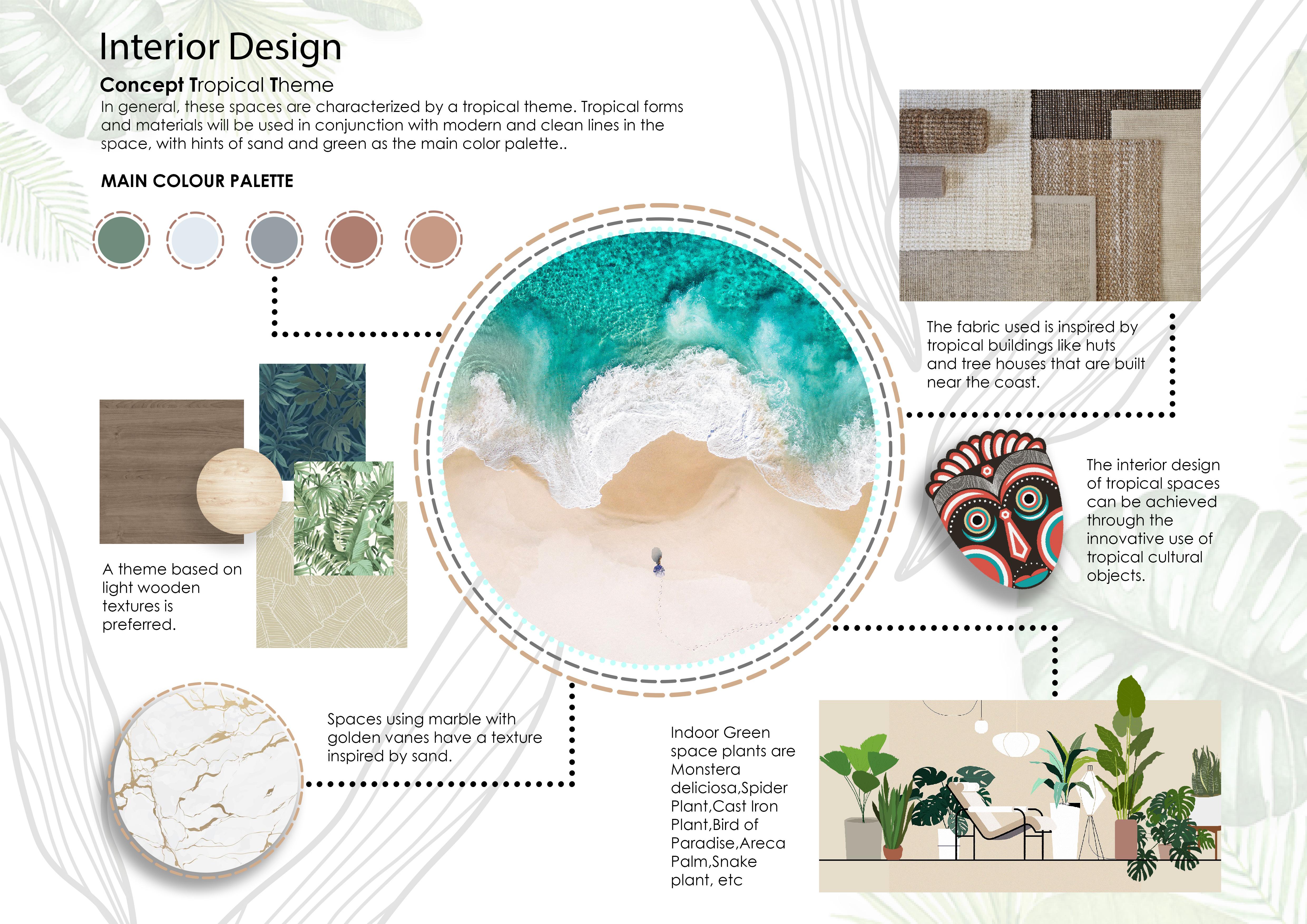
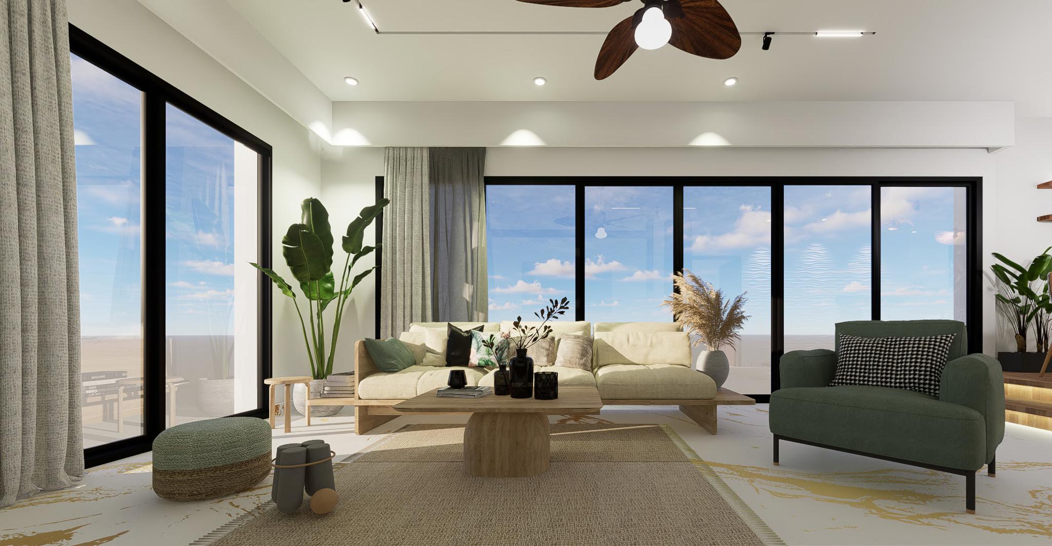
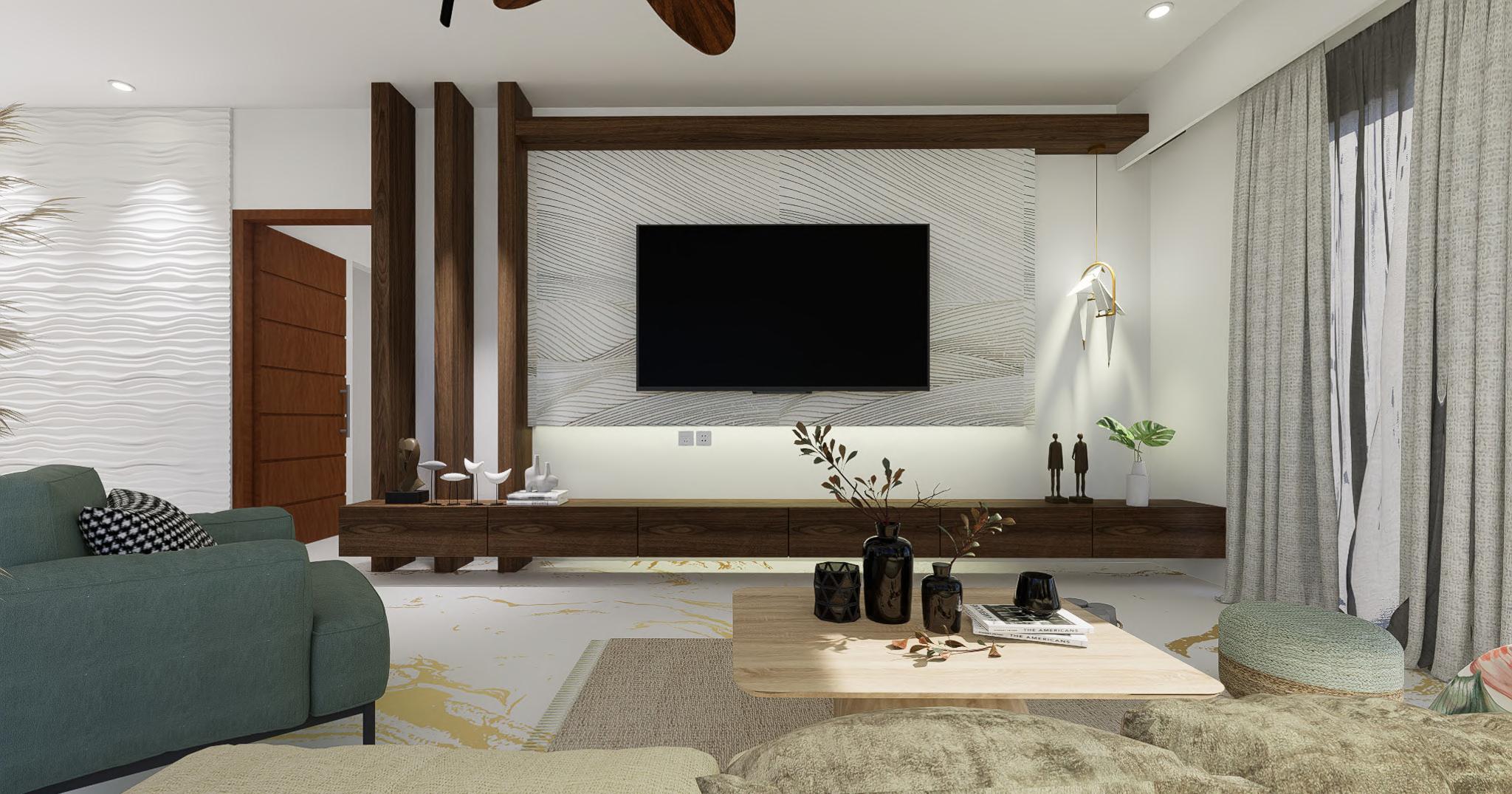
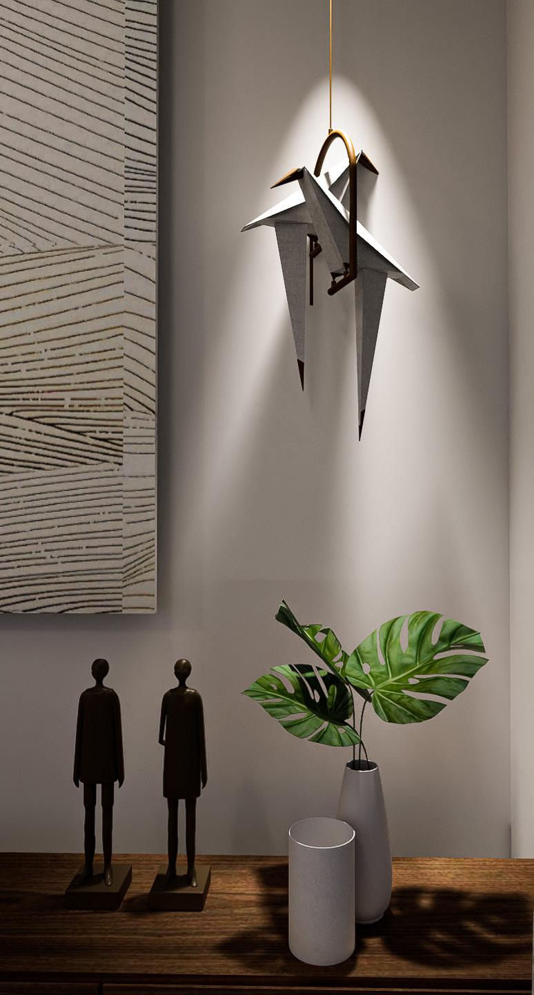
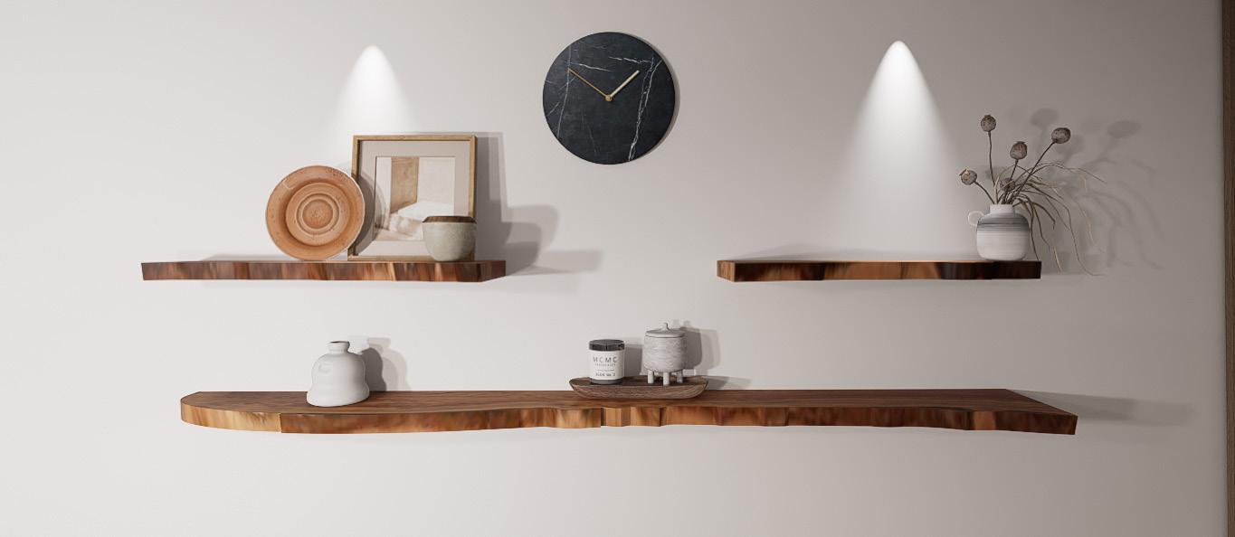
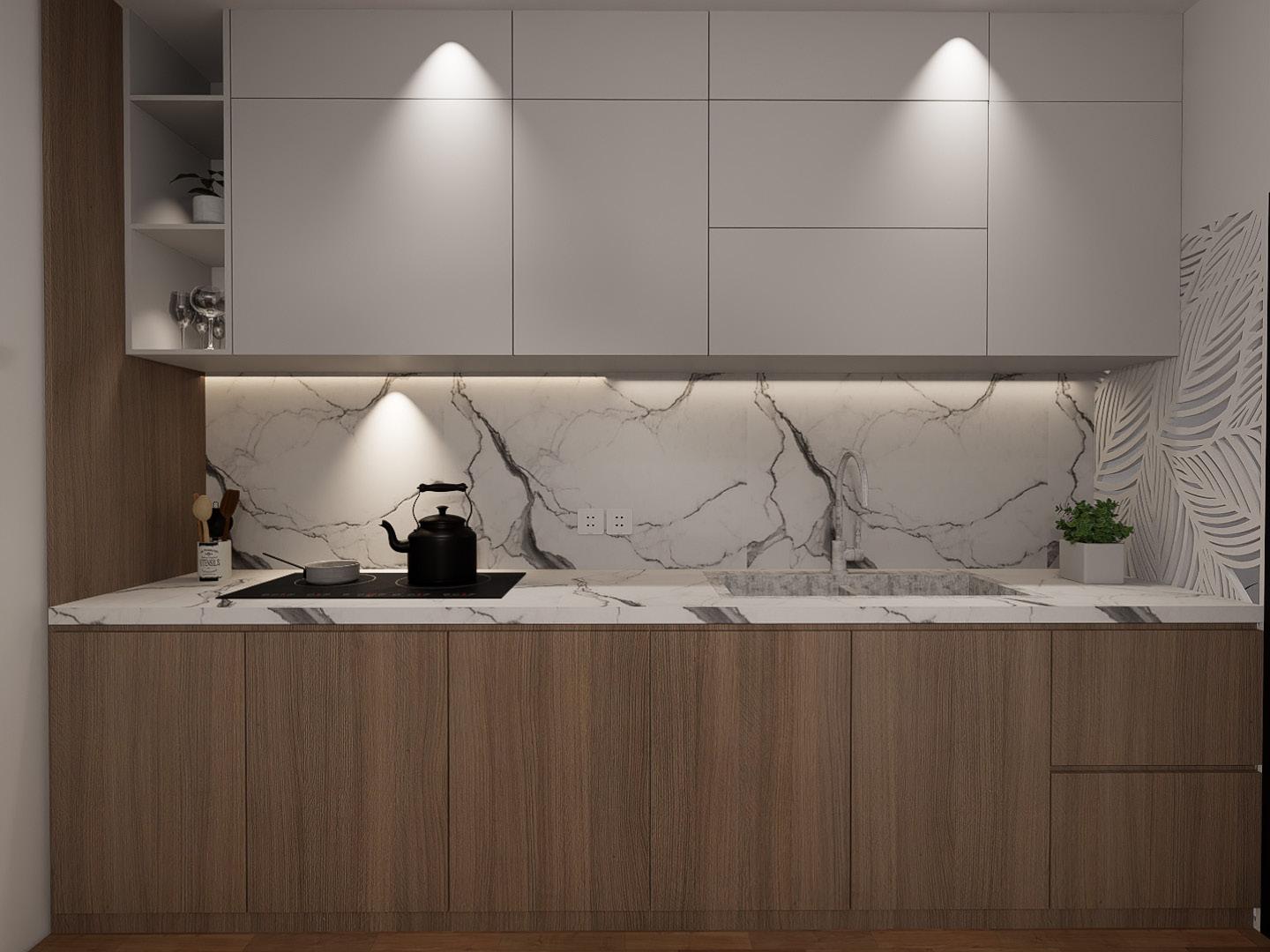
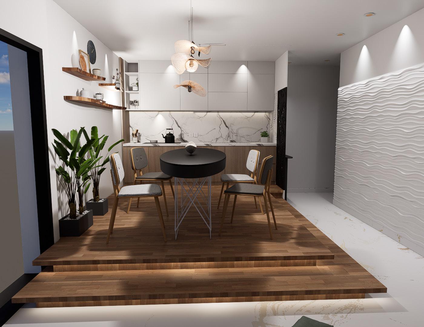
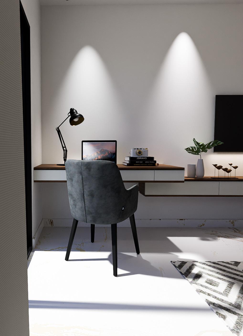
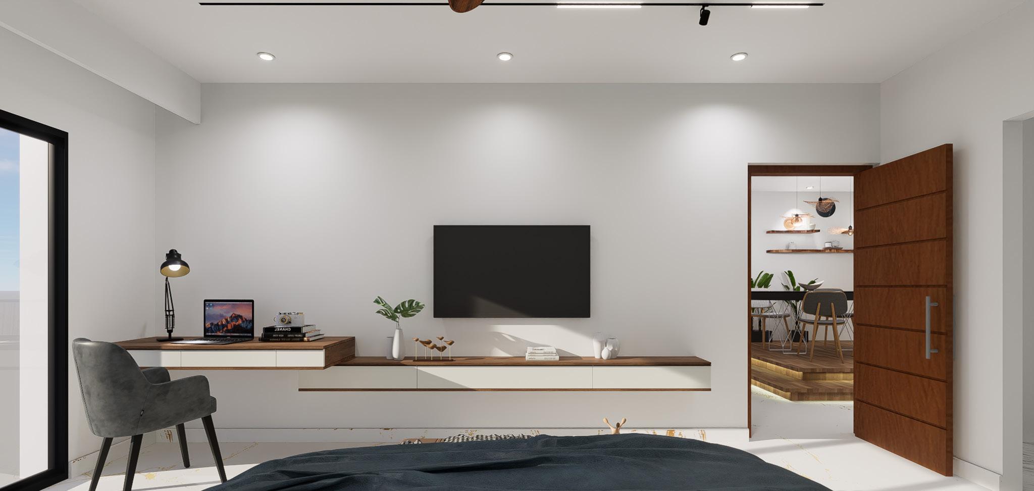
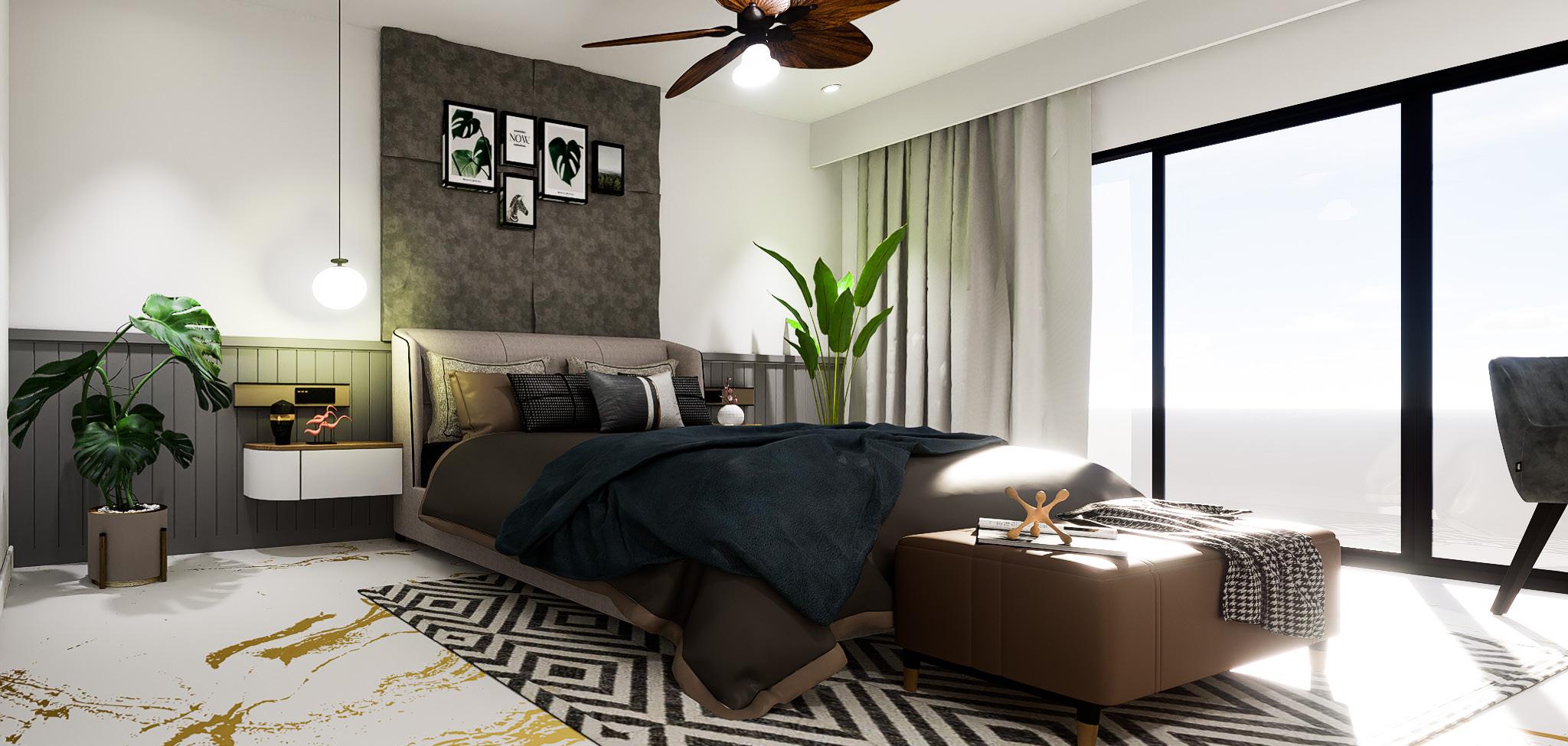
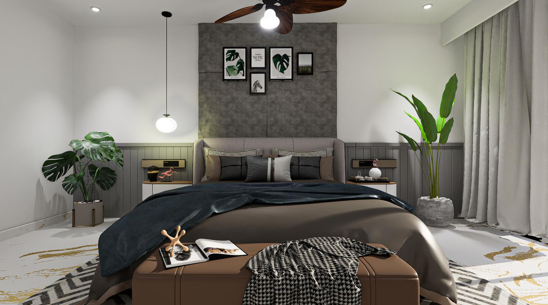
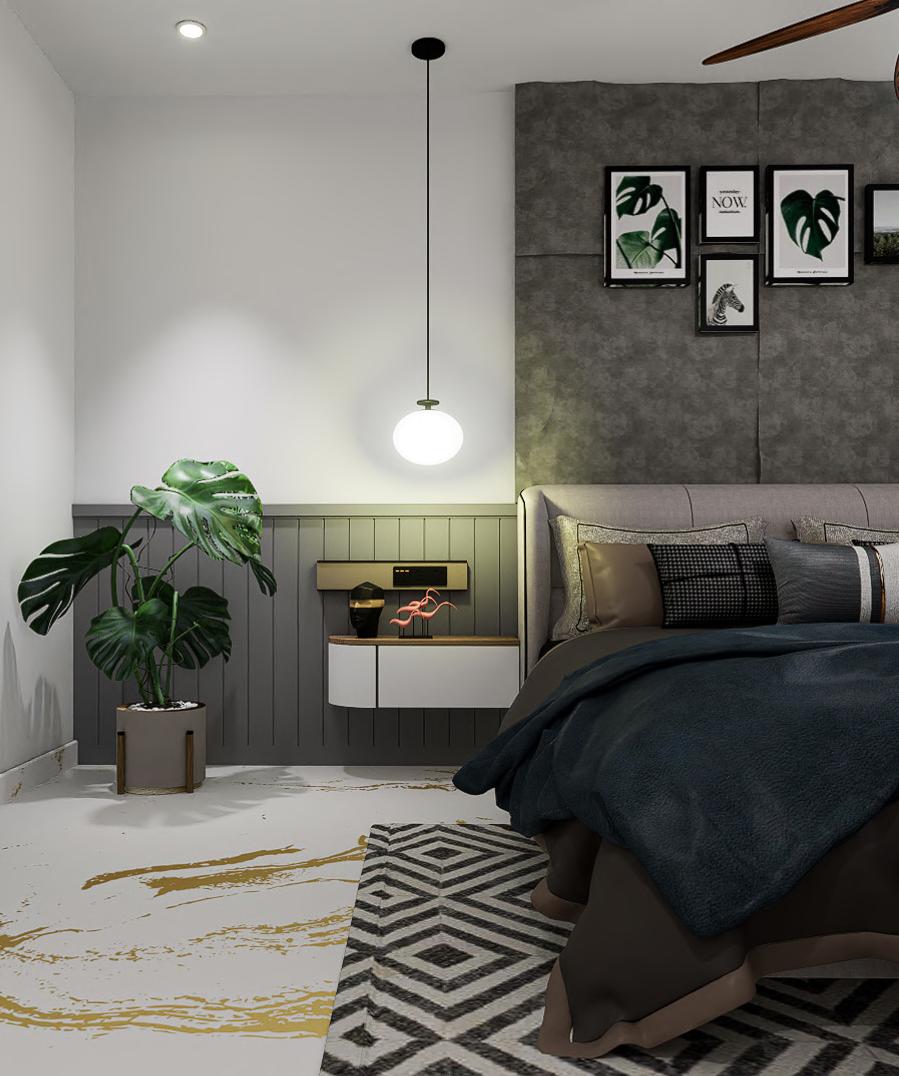
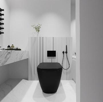
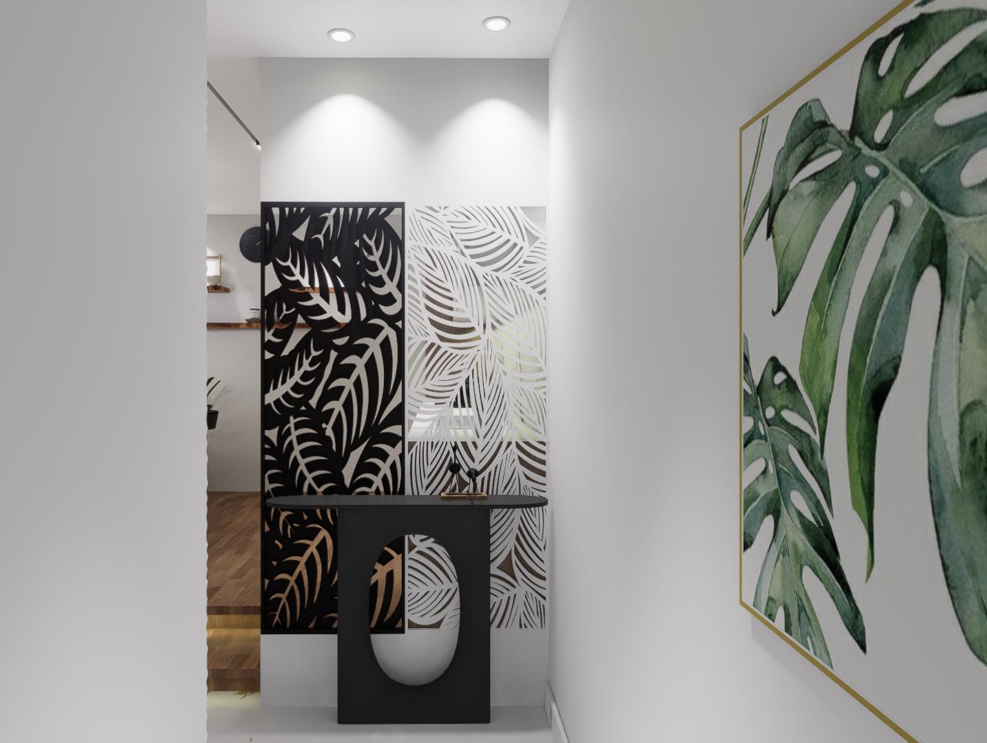
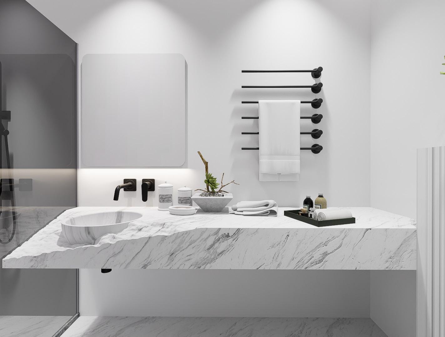
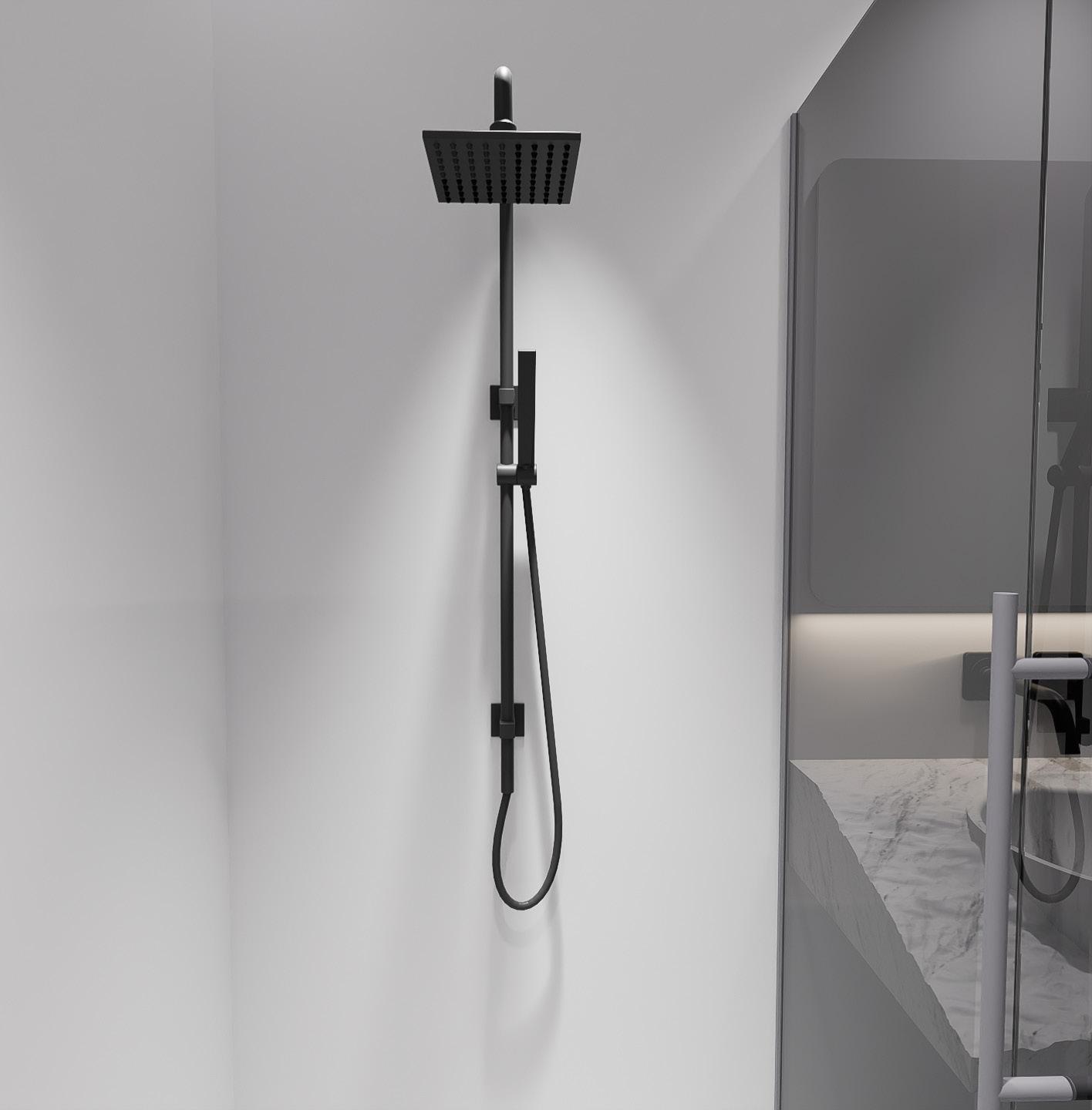
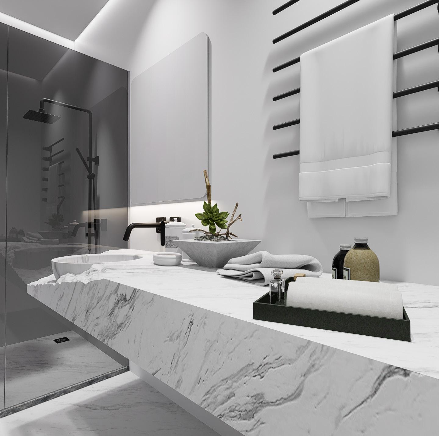
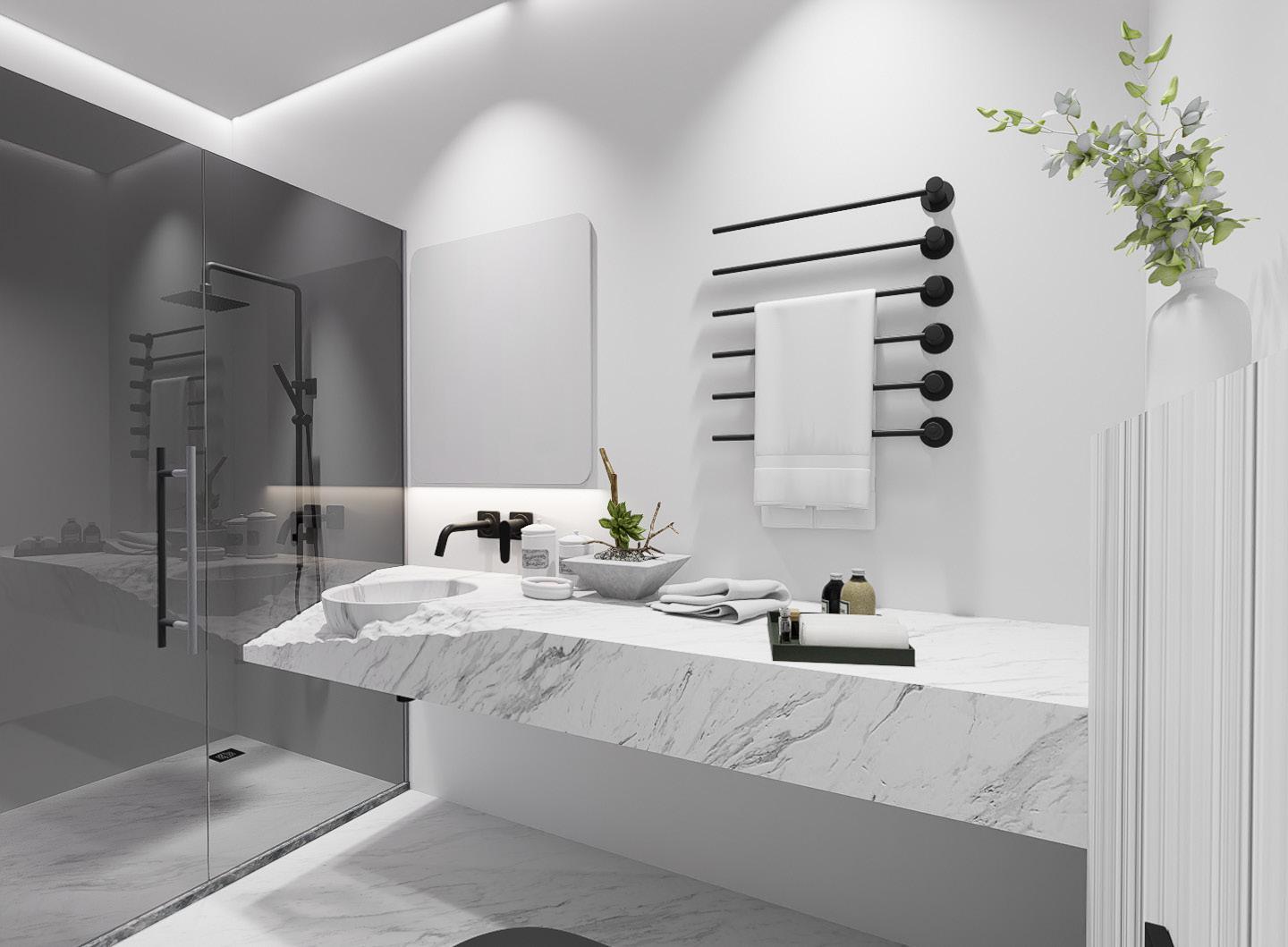
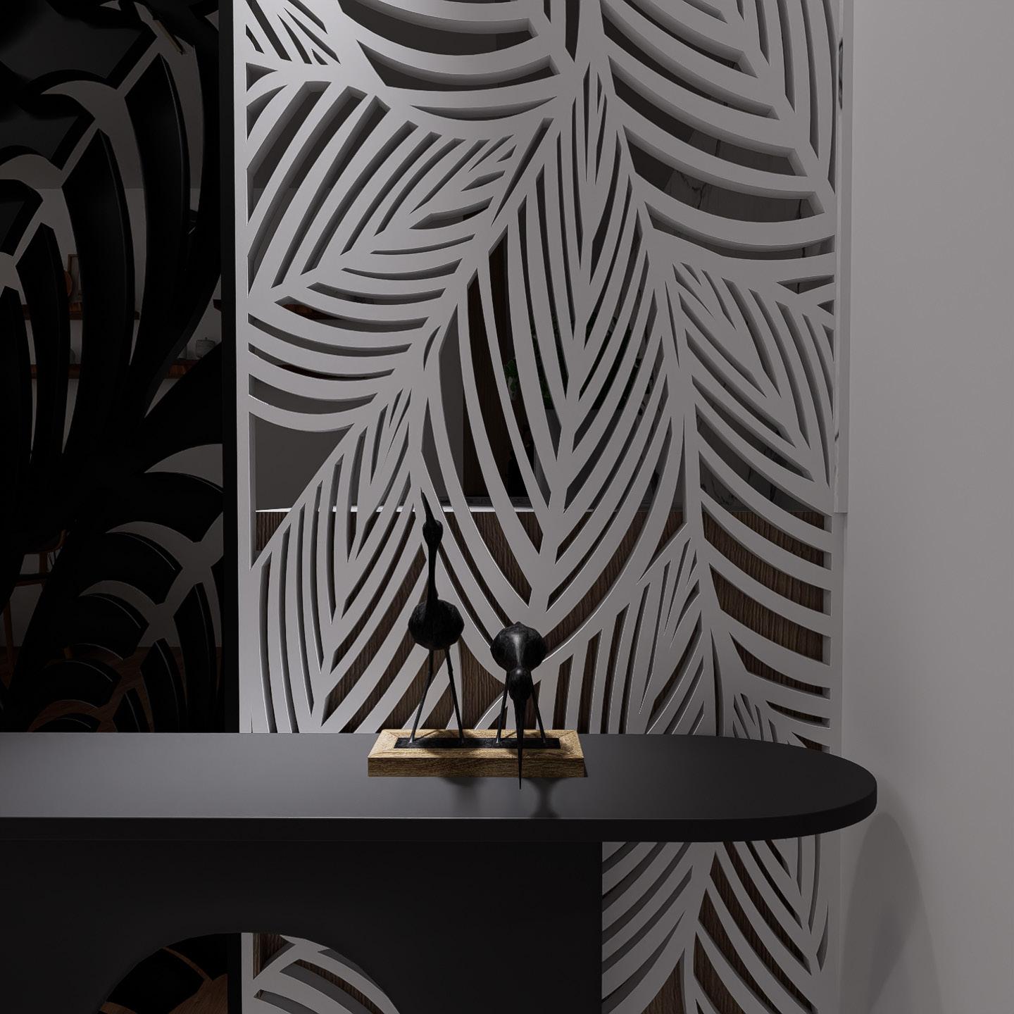
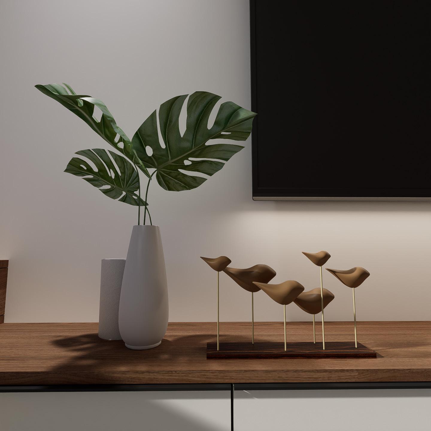
Interior Design
21-24
Working Drawing
25-26
Sketches
27-28

Row House
Academic project I Semester 03 I 2022
This row house design is located near a toll gate on the Tumkur to Bangalore highway. The site measures 60x18 meters and features a 9-meter wide road. The use of origami architecture creates a dynamic and ever-changing aesthetic for the buildings. A total of 6 row houses are included in the design, each with 3BHK and 1 home theatre.

The design emphasizes natural light and ventilation throughout each row house. Privacy, noise reduction, and energy efficiency are also important considerations in the design. The layout and arrangement of the buildings on the site are carefully planned. The changing shades and patterns with the movement of the sun enhance the visual appeal of the buildings.
This design offers a unique and visually stunning option for row house living. Overall, the design combines aesthetics, functionality, and sustainability to create a harmonious living environment.
Autocad I Sketchup I Lumion I Photoshop


Hotel
Academic project I Semester 07 I 2022
This hotel build features a dynamic facade that acts as the “skin” of the building, reducing heat gain from the sun and optimizing energy consumption for a sustainable and energy-efficient approach. The design prioritizes guest experience and efficient circulation, with well-planned interior spaces that enhance comfort. The dynamic facade adapts to environmental changes, further optimizing energy use. The project showcases a unique and innovative hotel design that blends sustainability and guest comfort in a functional and thoughtfully planned manner.
Illustrator I Procreate I D5 Render

Design Form :


Dynamic facades respond to environmental changes using advanced materials and control systems, optimizing energy efficiency and aesthetics. Building form is considered to make efficient use of space while minimizing waste and improving occupant comfort. Combining dynamic facades and innovative building form can lead to more sustainable and environmentally friendly structures. This approach can reduce energy consumption for lighting and cooling while improving the indoor environment. Overall, dynamic facades and innovative building form reduced environmental impact.

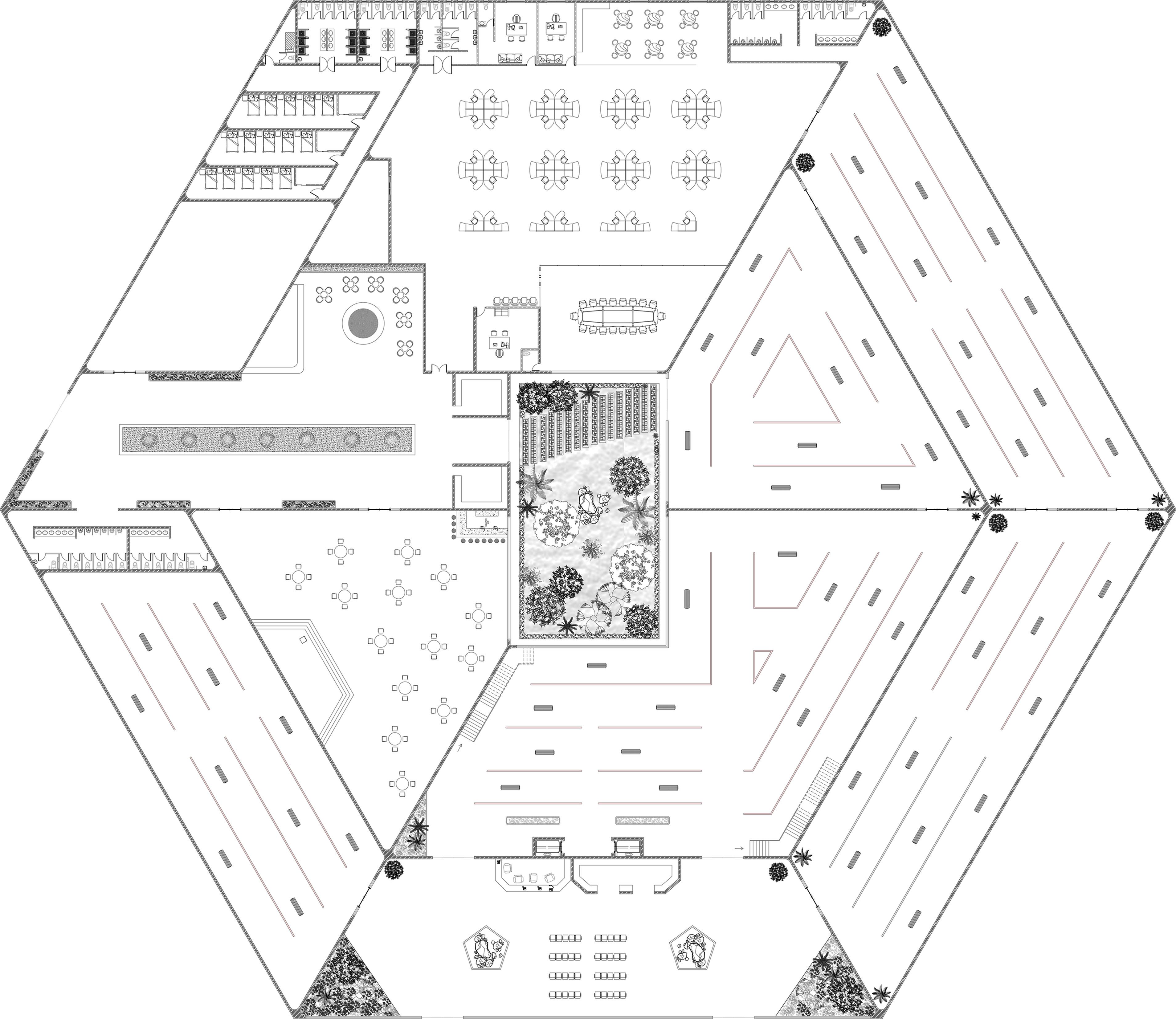
Ground Floor Plan :
1. Waiting Area- 485 sq m
2. Chairman office- 18 sq m
3. Toilets- 27 sq m
4. Cloakroom- 11 sq m

5. Electrical room- 2.8x2 sq m
6. Fire duct- 1.6x2 sq m

7. Service lift- 4x2 sq m
8. Public Lift- 4x4 sq m
9. Banquet hall 1- 155 sq m
10. Banquet hall 2- 314 sq m
11. Toilets- 46 sq m
12. Dining hall- 250 sq m
13. Kitchen- 107 sq m
14. Store room- 17 sq m
15. Cold storage- 14 sq m

16. Toilets- 22.8 sq m
Ground Floor Total Area=1500 sq m
Ground Floor Plan

First Floor Plan
First Floor Plan :
1. Waiting Area- 27.7 sq m
2. Gym area- 207.7 sq m
3. Changing room- 9.7x2 sq m

4. Spa- 220 sq m
5. Office space- 122 sq m
6. Discussion room- 82 sq m
7. Fire duct- 1.6x2 sq m
8. Electrical room- 2.8x2 sq m
9. Service lift- 4x2 sq m
10. Public Lift- 4x4 sq m
First Floor Total Area=711.6 sq m
3-5 Floor Plan :


Basement Floor Plan

Basement Floor Plan :

Terrace Floor Plan :
 1. Public Lift- 4x4 sq m
2. Fire duct- 1.6x2 sq m
3. Service lift- 4x2 sq m
4. Electrical room- 2.8x2 sq m
5. Bar - 19.8x2 sq m
6. Toilet - 13.5x2 sq m
7. Pool - 126 sq m
1. Public Lift- 4x4 sq m
2. Fire duct- 1.6x2 sq m
3. Service lift- 4x2 sq m
4. Electrical room- 2.8x2 sq m
5. Laundry room- 64.2 sq m
1. Public Lift- 4x4 sq m
2. Fire duct- 1.6x2 sq m
3. Service lift- 4x2 sq m
4. Electrical room- 2.8x2 sq m
5. Bar - 19.8x2 sq m
6. Toilet - 13.5x2 sq m
7. Pool - 126 sq m
1. Public Lift- 4x4 sq m
2. Fire duct- 1.6x2 sq m
3. Service lift- 4x2 sq m
4. Electrical room- 2.8x2 sq m
5. Laundry room- 64.2 sq m


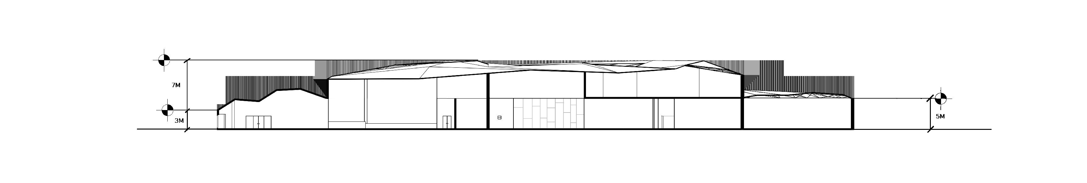
SECTION @ BB’
SECTION @ AA’

Hotel Renders


Dynamic Facade

Hotel facade that incorporates adaptive or dynamic facade design.
A dynamic facade is a skin that has evolved over time with the help of engineered solutions; its purpose is to assist in the progression of Sustainable and Responsive architecture.
Dynamic facades act as filters between the indoors and the outside, facilitating the users by providing shade, sunlight, ventilation and a visual union with the moving world outside. This idea isn’t new, but architects have only recently started incorporating it into their designs and structures.
hrough fully integrated design strategies, today’s facade can provide responsive and per-formative envelopes that both contextually and conceptually react to their local surroundings, whilst simultaneously determining interior conditions
In modern facade design, fins made from advanced materials are commonly used. These fins are strategically arranged to block direct sunlight, thereby reducing heat gain and improving the comfort of the building’s occupants. Additionally, the design of the fins also takes into consideration the flow of wind, allowing for good natural ventilation. By incorporating these features, modern facade design can help create more comfortable and sustainable buildings.


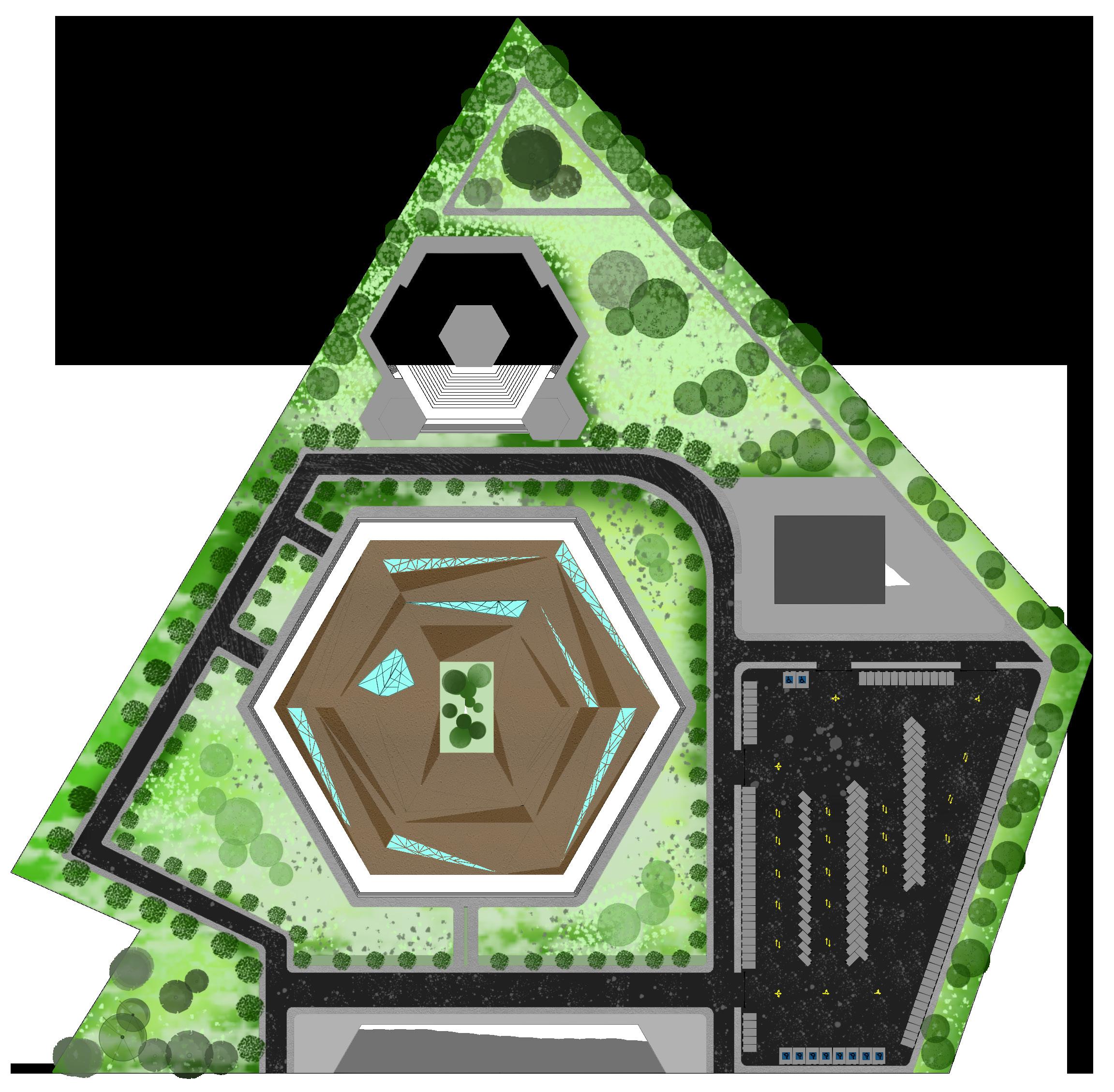
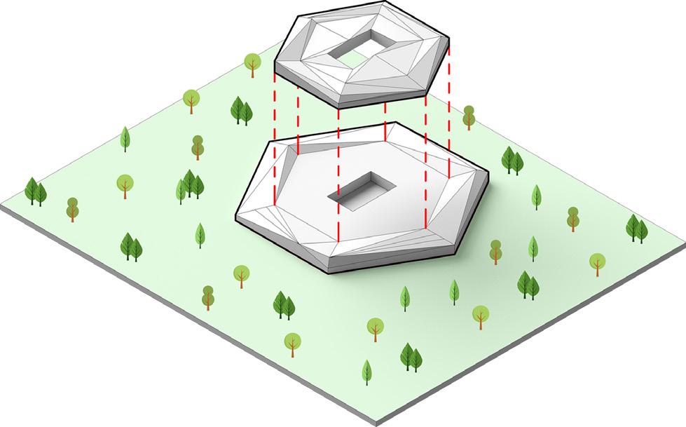
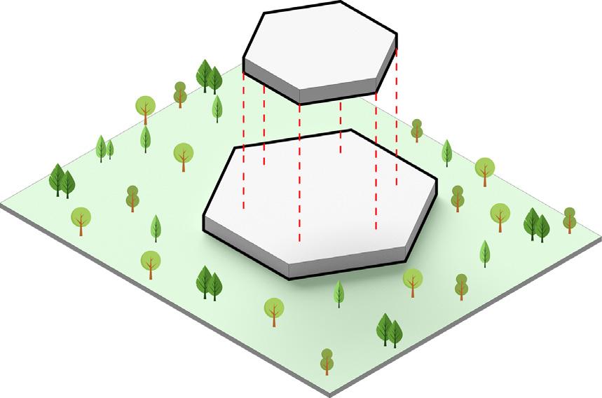
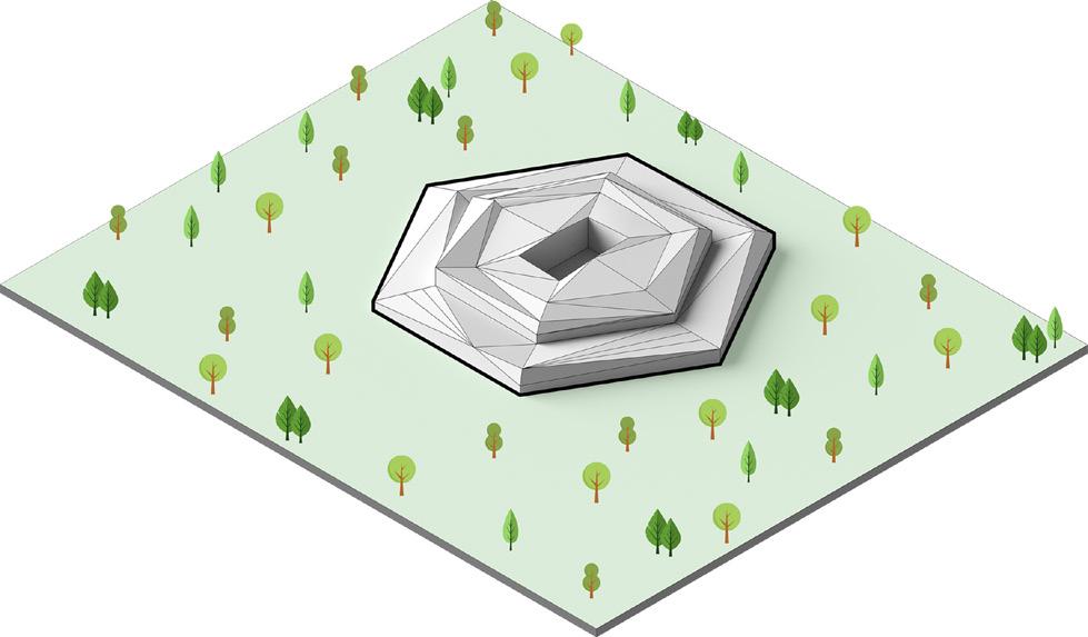
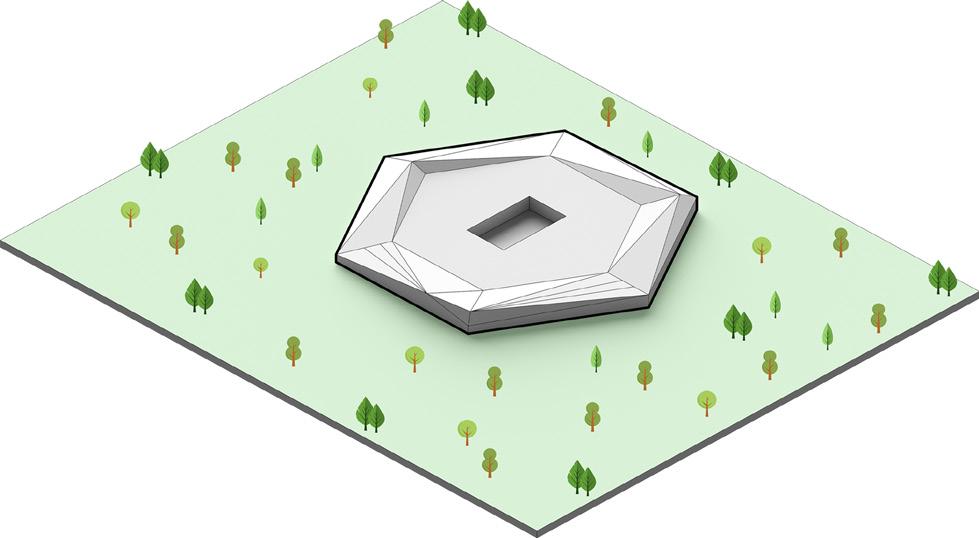
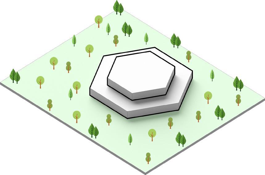
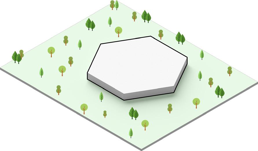
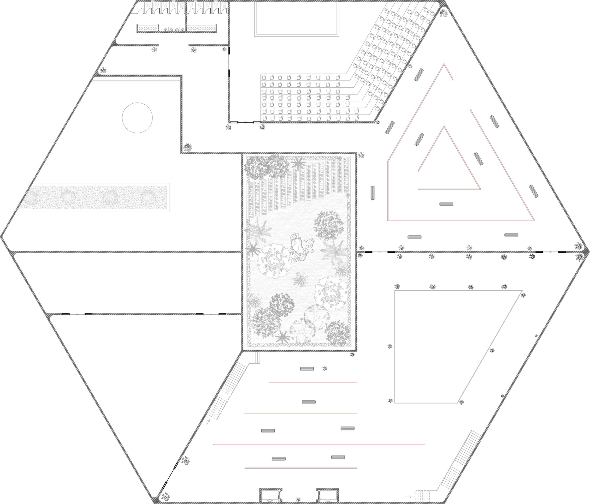
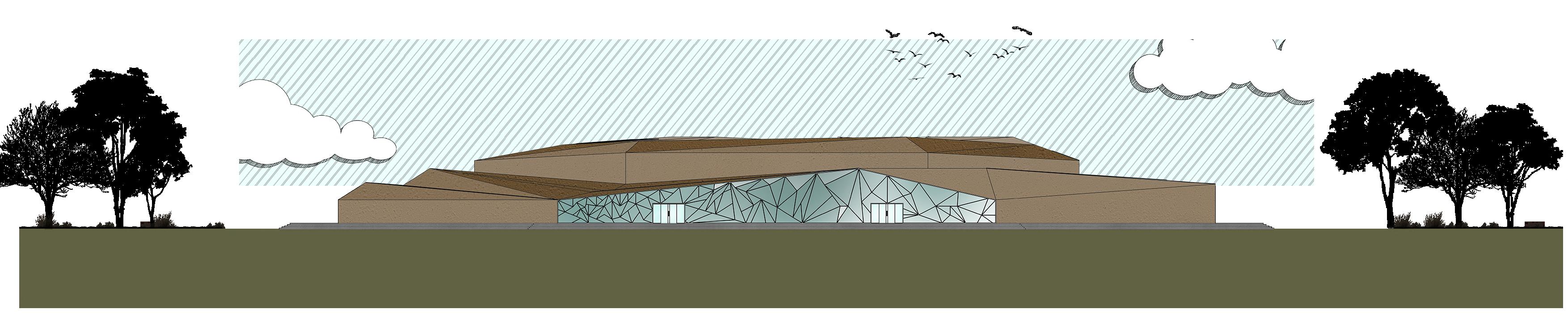
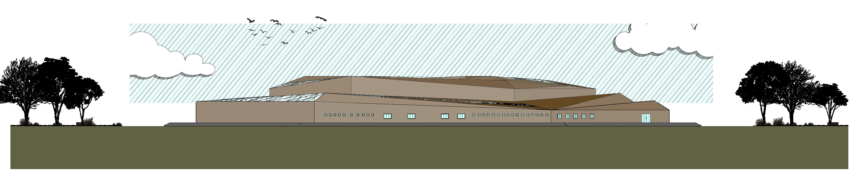
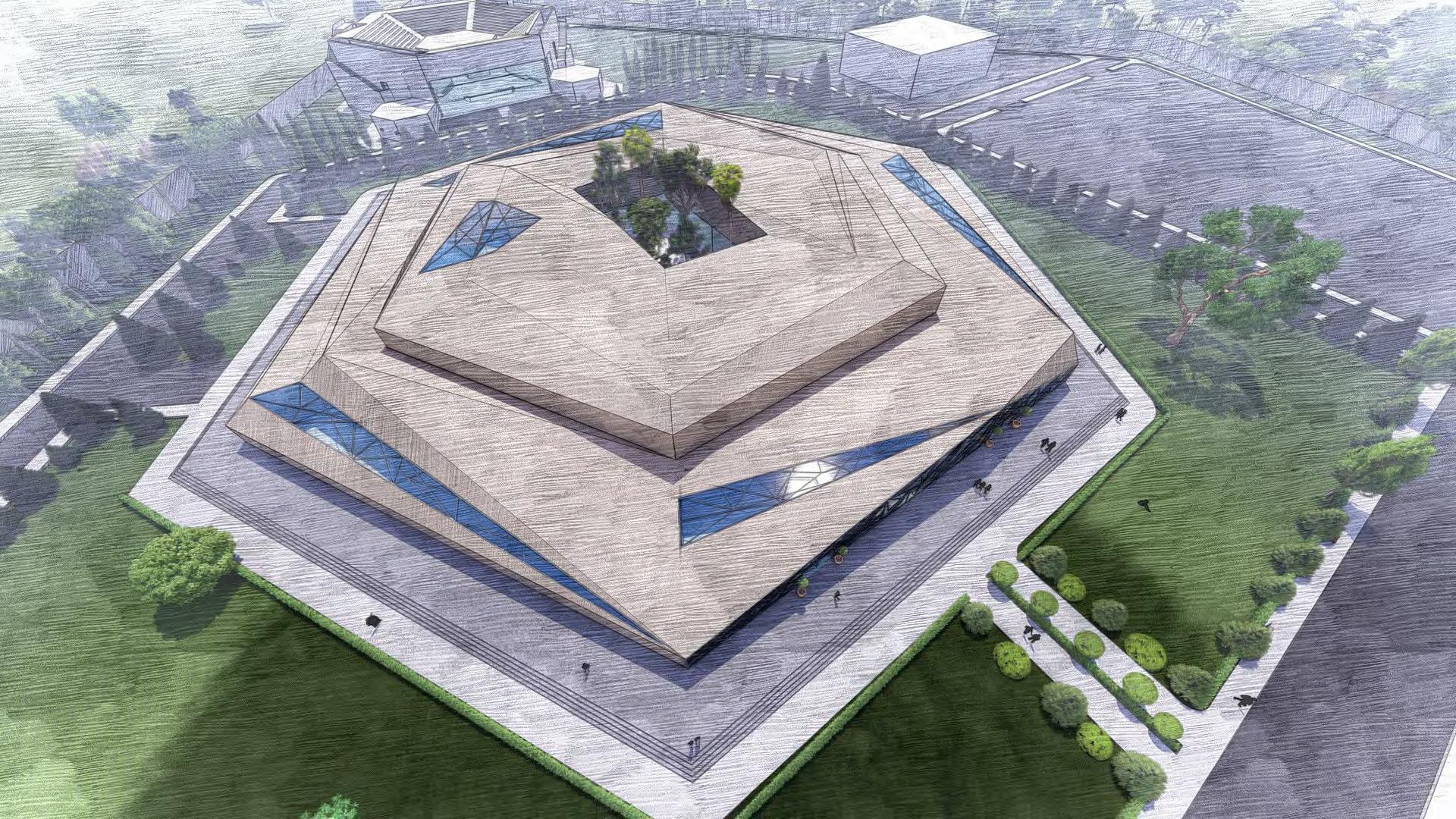
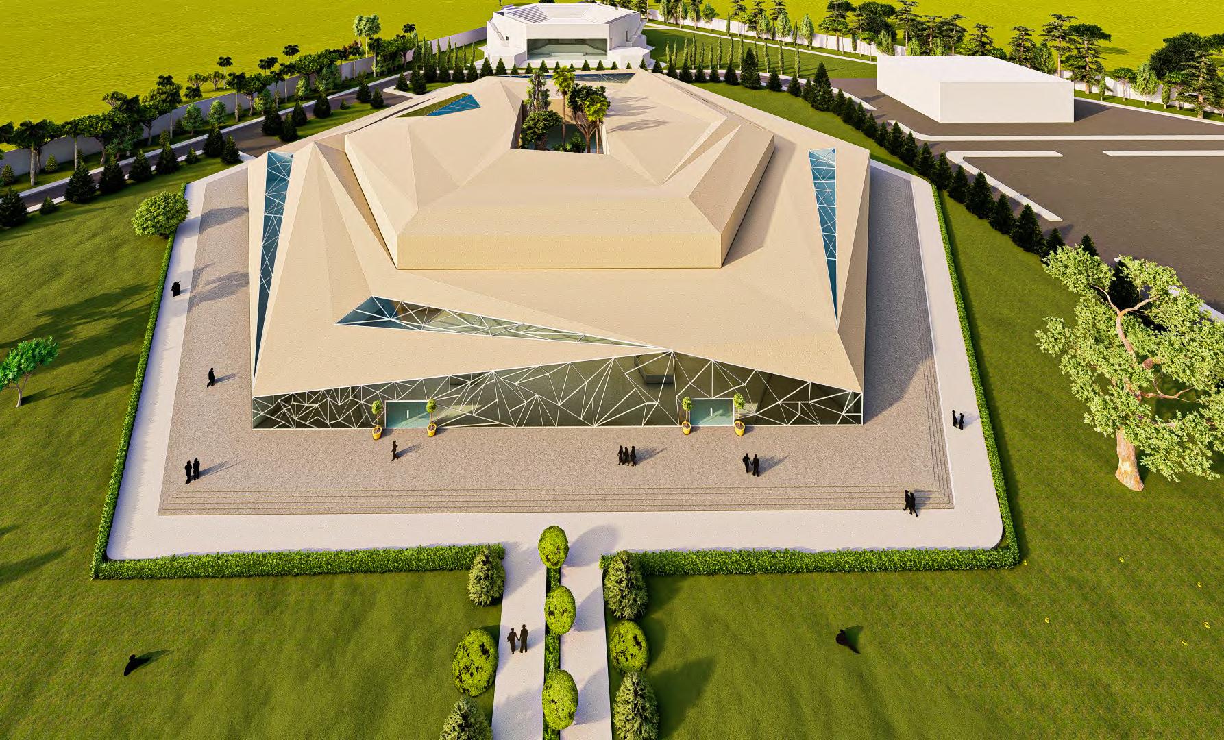
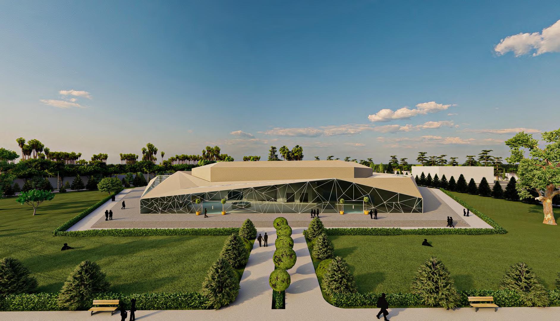
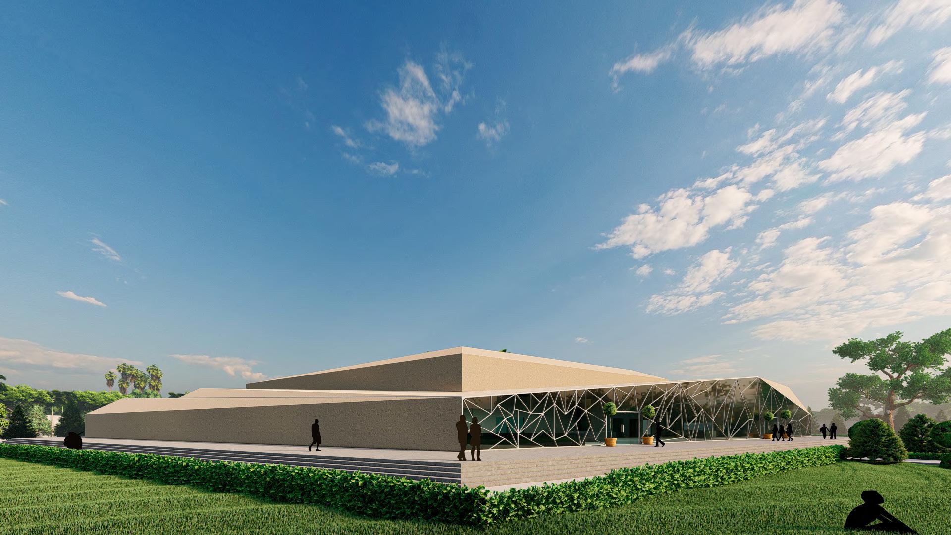
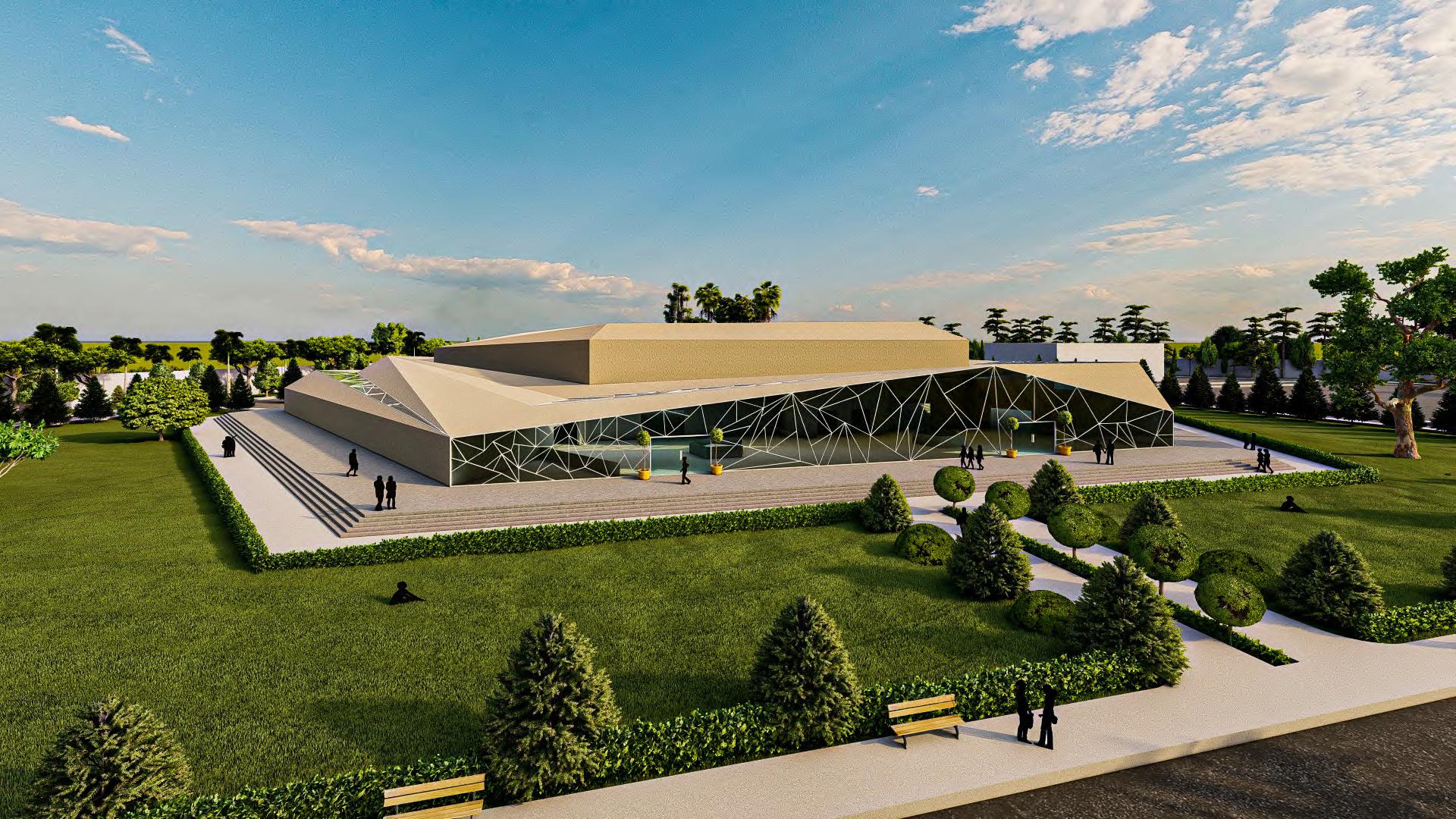
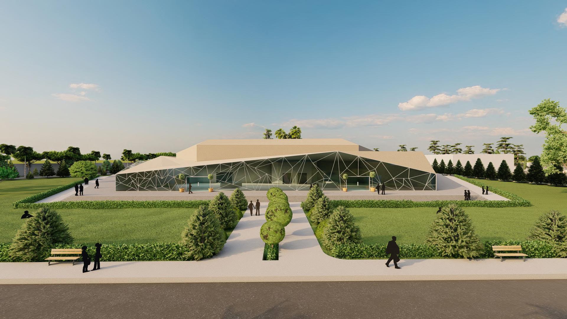
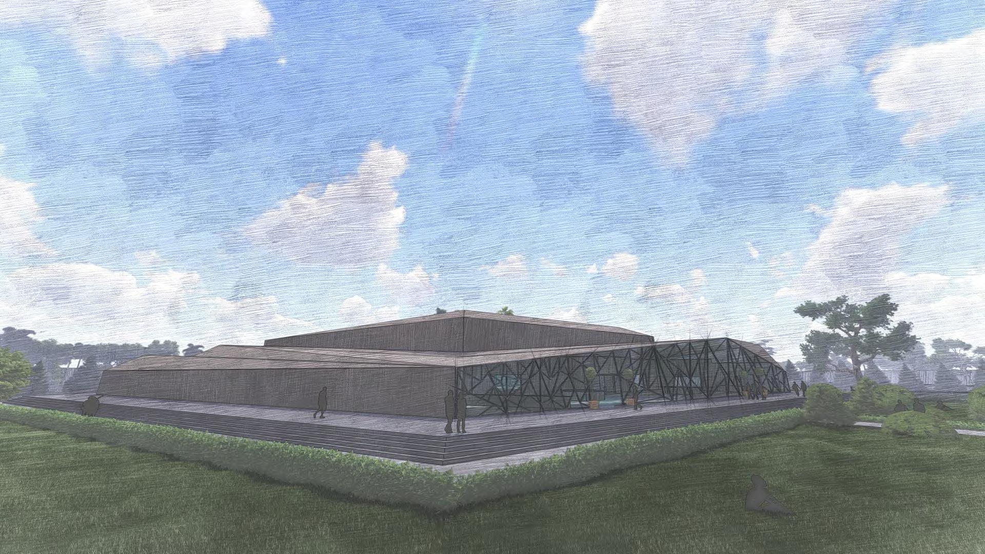
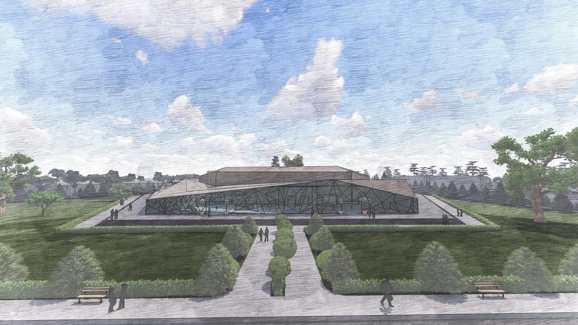
Art Gallery
Academic project I Semester 05 I 2021

The art gallery project near Tumkur covers an area of 58422 sq m and aims to attract people. To achieve this, the building has a unique facade with a folded roof that changes its appearance as the sun moves. This design not only adds to the building’s aesthetic appeal but also makes use of natural light and promotes sustainability. The project showcases an innovative and environmentally conscious approach to architecture, creating a space that is both visually appealing and functional.