SERVICE MANUAL TD4020F /TD4030F /TD4040F Tractor Part number 48064955 English September 2016 © 2016 CNHI International. All Rights Reserved.

Link Product / Engine Product Market Product Engine TD4020F Europe F5AE5484A TD4030F Europe F5AE5484A TD4040F Europe F5AE5484A 48064955 19/12/2016
Contents INTRODUCTION Engine...............................................................................................................10 [10.001] Engine and crankcase........................................................................................................10.1 Clutch................................................................................................................18 [18.110] Clutch and components 18.1 Transmission....................................................................................................21 [21.114] Mechanical transmission....................................................................................................21.1 [21.160] Creeper ................................................................................................................................21.2 [21.162] Reverser...............................................................................................................................21.3 [21.182] Differential............................................................................................................................21.4 Four-Wheel Drive (4WD) system..................................................................23 [23.202] Electro-hydraulic control....................................................................................................23.1 [23.304] Four Wheel Drive (4WD) gearbox 23.2 Front axle system............................................................................................25 [25.100] Powered front axle..............................................................................................................25.1 [25.102] Front bevel gear set and differential.................................................................................25.2 [25.108] Final drive hub, steering knuckles, and shafts................................................................25.3 [25.310] Final drives...........................................................................................................................25.4 Rear axle system.............................................................................................27 [27.100] Powered rear axle 27.1 [27.106] Rear bevel gear set and differential 27.2 Power Take Off (PTO)....................................................................................31 [31.101] Rear mechanical control....................................................................................................31.1 Brakes and controls........................................................................................33 [33.220] Trailer brake hydraulic control 33.1 [33.202] Hydraulic service brakes 33.2 48064955 19/12/2016
Hydraulic systems...........................................................................................35 [35.204] Remote control valves........................................................................................................35.1 [35.114] Three point hitch control valve...........................................................................................35.2 [35.322] Regulated/Low pressure system.......................................................................................35.3 Hitches, drawbars, and implement couplings .............................................37 [37.110] Rear three point hitch 37.1 Steering.............................................................................................................41 [41.206] Pump 41.1 [41.216] Cylinders 41.2 [41.200] Hydraulic control components 41.3 Electrical systems............................................................................................55 [55.301] Alternator..............................................................................................................................55.1 [55.201] Engine starting system.......................................................................................................55.2 [55.051] Cab Heating, Ventilation, and Air-Conditioning (HVAC) controls..................................55.3 [55.523] Cab hitch controls................................................................................................................55.4 [55.408] Warning indicators, alarms, and instruments...................................................................55.5 [55.302] Battery...................................................................................................................................55.6 [55.100] Harnesses and connectors.................................................................................................55.7 Platform, cab, bodywork, and decals...........................................................90 [90.154] Cab doors and hatches 90.1 [90.151] Cab interior 90.2 48064955 19/12/2016
INTRODUCTION 48064955 19/12/2016 1

Contents INTRODUCTION International symbols ..............................................................................................................................3 Safety rules...............................................................................................................................................4 Safety rules.............................................................................................................................................16 Personal safety.......................................................................................................................................21 Basic instructions Hardware.................................................................................................................22 Torque Specification Tables.................................................................................................................23 Basic instructions Shop and Assembly ............................................................................................28 Capacities ...............................................................................................................................................30 48064955 19/12/2016 2
engagedgears INTRODUCTION International symbols As a guide to the operation of the machine, various universal symbols have been utilized on the instruments, controls, switches, and fuse box. The symbols are shown below with an indication of their meaning. startingThermostartaid Radio PTO ControlPosition chargeAlternator Keep memoryalive inTransmissionneutral ControlDraft Fuel level Turn signals Creeper socketAccessory Hours(rev/minEngineFuelAutomaticshutoffspeedx100)recordedEngineoilpressureEnginecoolanttemperature Turn signals one trailer Turn signals two screenscreenFronttrailerswind-wash/wipeRearwindwash/wipeHeatertemperaturecontrol Slow or low peratureoilRearlockDifferentialspeedGroundsettingFastsettingorhighaxletem limitHitch(rear)Hitch(rear)Hitchslip%agesocketImplementraiselowerheight(rear) levelCoolant oilTransmissionpressure Hitch height limit (front) Tractor lights Air conditioner FWD Hitch ableddis mainHeadlampbeam Air blockedfilter FWD engageddis Hydraulic filterstransmissionand dippedHeadlampbeam brakeParking Warning! Remotevalveextend Work lamps Brake fluid level warningHazard lights valveRemoteretract HornlampsStop WarningbeaconRoofbrakeTrailer substanceCorrosive! OpenPressurised!controlVariablecarefully native(alterMalfunction!ManualSeeMalfunction!valveRemotefloatOperator'ssymbol) 48064955 19/12/2016 3 Heater fan


The words “front”, “rear”, “right hand”, and “left hand” refer to the different parts as seen from the operator’s seat oriented to the normal direction of movement of the tractor.
DANGER INTRODUCTION
Equipment shown in this manual is:
Most accidents and personal injuries taking place in workshops are due from non observance of some essential rules and safety precautions. The possibility that an accident might occur with any type of machines should not be disregarded, no matter how well the machine in question was designed and built. A wise and careful service technician is the best precautions against accidents. Careful observance of this basic precaution would be enough to avoid many severe accidents.
All maintenance and repair operations described in this manual should be carried out exclusively by authorised work shops. All instructions should be carefully observed and special equipment where indicated should be used.
NOTES
This warning symbol points out important messages involving personal safety. Carefully read the safety rules contained herein and follow advised precautions to avoid potential hazards and safeguard your safety. In this manual you will find this symbol together with the following key WARNINGwords: it gives warning about improper repair operations and potential consequences affecting the service technician’s personal safety.
ACCIDENTS
Never carry out any cleaning, lubrication or maintenance operations when the engine is running.
B013
SAFETY RULES Generalities
48064955 19/12/2016 4
SAFETY RULES PAY ATTENTION TO THIS SYMBOL
• designed expressly for use on these tractors; • necessary to make a reliable repair; • accurately built and strictly tested to offer efficient and long-lasting working life.
DANGER - it gives specific warning about potential dangers for personal safety of the operator or other persons directly or indirectly involved in the operation.
Anyone who carries out service operations described without carefully observing these instructions will be directly responsible for any damage caused. FOR EQUIPMENT
TO PREVENT
Safety rules IMPORTANT NOTICE
NOTICES
• Carefully follow specified repair and maintenance procedures.


• Never bring your head, body, arms, legs, feet, hands, fingers near fans or rotating belts.
• Never check or fill fuel tanks or batteries, nor use starting liquid if you are smoking or near open flames as such fluids are flammable.
• Never carry out any repair on the machine if someone is sitting on the operator’s seat, except if they are qualified operators assisting in the operation to be carried out.
• The fuel filling gun should always remain in contact with the filler neck. Maintain this contact until the fuel stops flowing into the tank to avoid possible sparks due to static electricity build up.
• Always use lifting equipment of appropriate capacity to lift or move heavy components.
• Chains should always be safely fastened. Ensure that fastening device is strong enough to hold the load foreseen. No persons should stand near the fastening point.
• The working area should be always kept CLEAN and DRY. Immediately clean any spillage of water or oil.
• Never use gasoline, diesel oil or other flammable liquids as cleaning agents. Use non flammable non toxic propri etary solvents.
• Never adjust the fuel injection pump when the tractor is moving.
• Never operate the machine or use attachments from a place other than sitting at the operator’s seat or at the side of the machine when operating the fender switches.
• Never lubricate the tractor when the engine is running.
ELECTRICAL SYSTEMS
• Disconnect the batteries and label all controls to warn that the tractor is being serviced. Block the machine and all equipment which should be raised.
START UP • Never run the engine in confined spaces which are not equipped with adequate ventilation for exhaust gas extrac tion.
• Do not pile up grease or oil soaked rags, as they constitute a great fire hazard. Always place them into a metal container.
• All repair and maintenance operations should be carried out with the greatest care and attention.
• Always loosen the radiator cap very slowly before removing it to allow pressure in the system to dissipate. Coolant should be topped up only when the engine is stopped.
• Do not fill up fuel tank when the engine is running.
• Damaged or frayed wires and chains are unreliable. Do not use them for lifting or towing.
• If it is necessary to use auxiliary batteries, cables must be connected at both sides as follows: (+) to (+) and ( ) to ( ). Avoid short circuiting the terminals. GAS RELEASED FROM BATTERIES IS HIGHLY FLAMMABLE. During 48064955 19/12/2016 5
INTRODUCTION
• Never carry out any operation on the machine when the engine is running, except when specifically indicated. Stop the engine and ensure that all pressure is relieved from hydraulic circuits before removing caps, covers, valves, etc.
• To load and unload the machine from the transportation means, select a flat area providing a firm support to the trailer or truck wheels. Firmly tie the machine to the truck or trailer platform and block wheels as required by the transporter.
• Wear suitable protection such as approved eye protection, helmets, special clothing, gloves and footwear whenever welding. All persons standing in the vicinity of the welding process should wear approved eye protection. NEVER LOOK AT THE WELDING ARC IF YOUR EYES ARE NOT SUITABLY PROTECTED.
• To transfer a failed tractor, use a trailer or a low loading platform trolley if available.
ENGINE
• Do not wear rings, wristwatches, jewels, unbuttoned or flapping clothing such as ties, torn clothes, scarves, open jackets or shirts with open zips which could get caught on moving parts. Use approved safety clothing such as anti slipping footwear, gloves, safety goggles, helmets, etc.
• Wear safety glasses with side guards when cleaning parts using compressed air.
SERVICE MANUAL Engine TD4040FTD4030FTD4020F 48064955 19/12/2016 10
Contents Engine - 10 [10.001] Engine and crankcase............................................................................................................10.1 48064955 19/12/2016 10
Engine - 10 Engine and crankcase - 001 TD4040FTD4030FTD4020F 48064955 19/12/2016 10.1 [10.001] / 1
Contents Engine - 10 Engine and crankcase - 001 SERVICEEngine Remove 3 Install 14 48064955 19/12/2016 10.1 [10.001] / 2
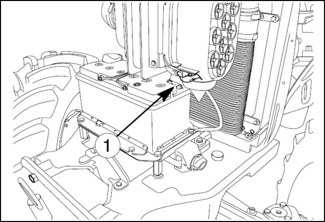
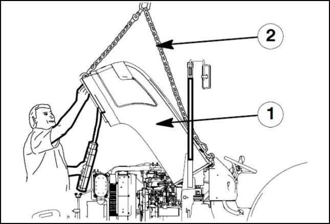
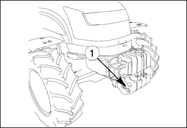
Engine Engine and crankcase Engine - Remove To access the clutch it is necessary to separate the en gine complete with the front axle from the transmission. Proceed as follows: 1. Disconnect the battery negative lead (1) 2. Drain the oil from the transmission gearbox housing. 3. Drain the cooling system. 4. Remove the exhaust pipe. Attach lifting chains (2) to the bonnet (1) and attach the chain to the hoist. 5. Disconnect the electrical connection (1) of bonnet. ANIL16TRO2582AA 1 ANIL16TRO2583AA 2 ANIL16TRO2584AA 3 48064955 19/12/2016 10.1 [10.001] / 3
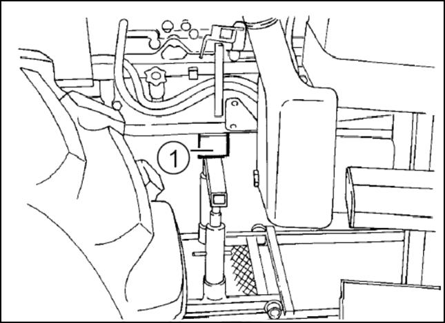
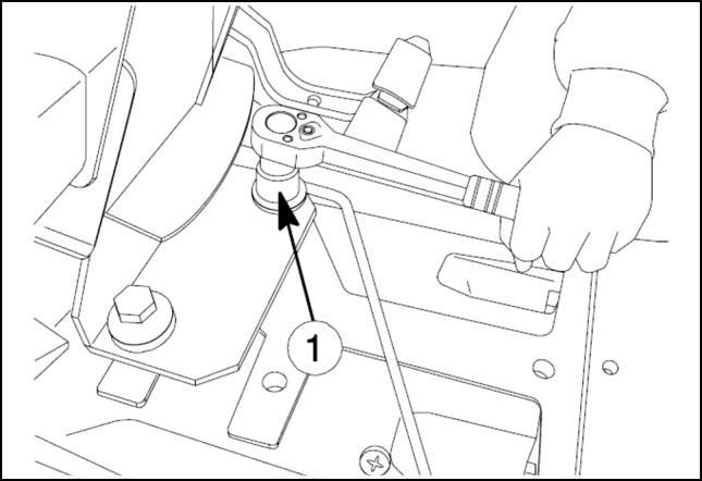
Engine Engine and crankcase 6. Detach the gas strut (1) from the bonnet. 7. Remove the two bonnet hinge bolts (1) and take out the spacers (2) lift the bonnet clear. 8. Remove the three retaining bolts (1) and the guard (2) both on the right and left hand side of the engine. 9. Unscrew the nut (1) from the weight retaining pin. Re move the weights from the front support. ANIL16TRO2585AA 4 ANIL16TRO2586AA 5 ANIL16TRO2587AA 6 ANIL16TRO2588AA 7 48064955 19/12/2016 10.1 [10.001] / 4
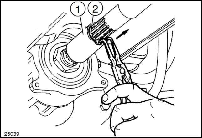
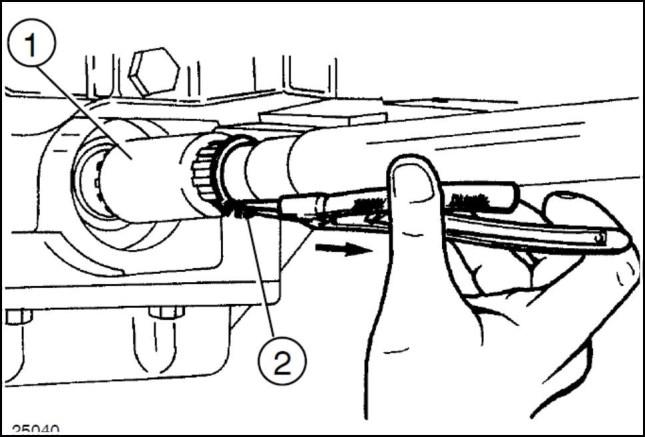
12. Remove the circlip (2) and move the rear sleeve (1) in the direction indicated by the arrow until it is released from the groove on the drive.
13. Remove the propeller shaft central support (1) retain ing bolts (2) and extract the shaft together with the support
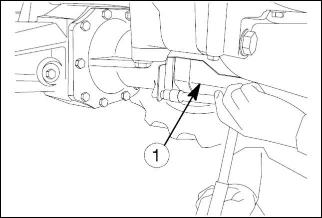
11. Remove the circlip (2) and move the front sleeve (1) in the direction indicated by the arrow until it is released from the groove on the front axle.
Engine Engine and crankcase
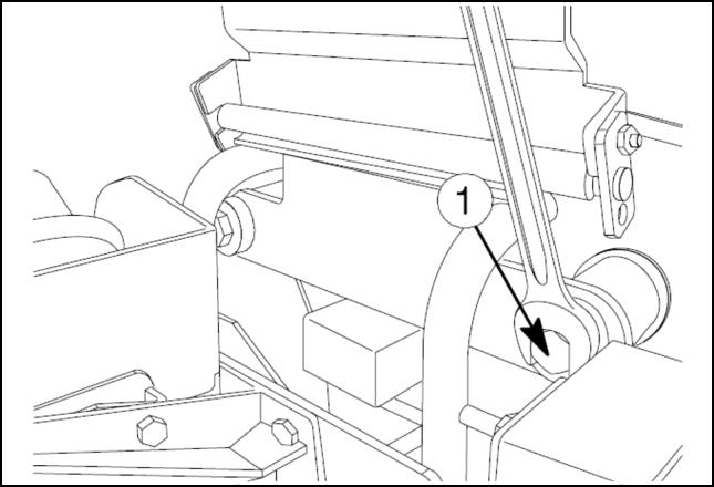
10. Unscrew the front central and rear retaining bolts on the front axle shaft guard, then remove the guard (1)
ANIL16TRO2589AA 8 ANIL16TRO2590AA 9 ANIL16TRO2591AA 10 ANIL16TRO2592AA 11 48064955 19/12/2016 10.1 [10.001] / 5
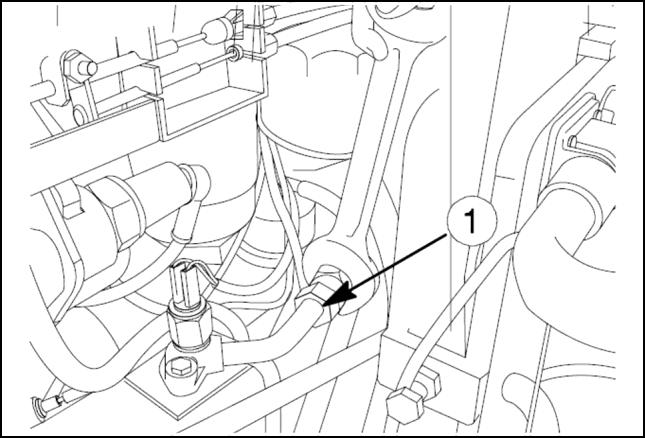
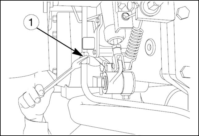
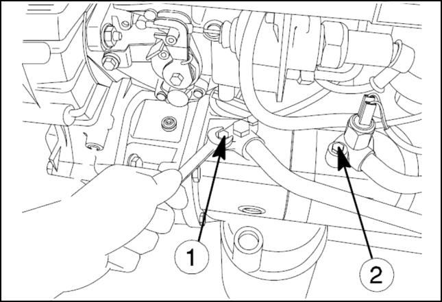
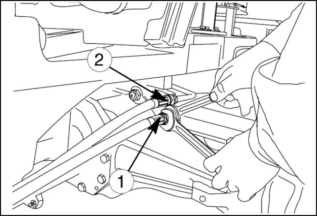
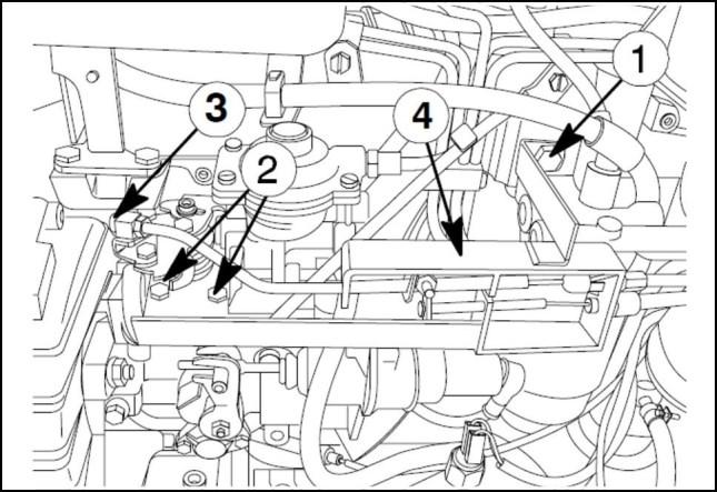
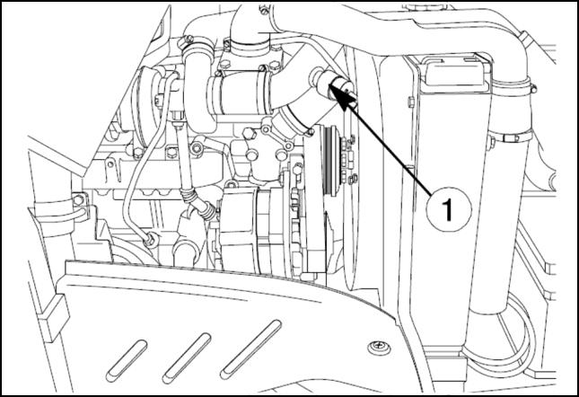
Engine Engine and crankcase 14. Disconnect the pressure pipe connection (1) of the hydrostatic steering pump. 15. Disconnect the pressure pipe connection (1) of the lift pump. 16. Disconnect the delivery lines of both hydraulic lift pump (1) and hydrostatic steering pump (2) 17. Detach the diesel recovery pipe (3) and delivery pipe (2) to the diesel pump (1) ANIL16TRO2593AA 12 ANIL16TRO2594AA 13 ANIL16TRO2595AA 14 ANIL16TRO2596AA 15 48064955 19/12/2016 10.1 [10.001] / 6
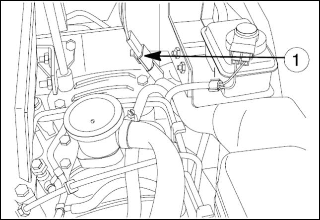
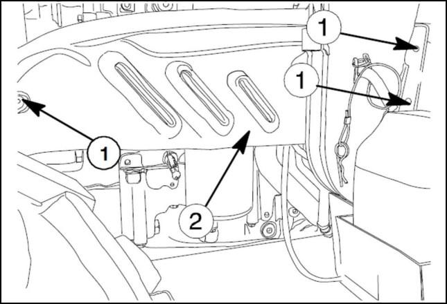
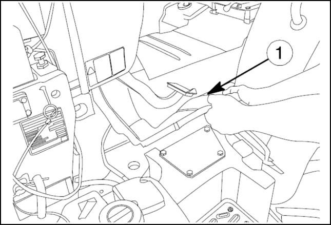
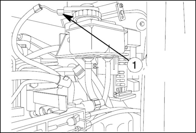
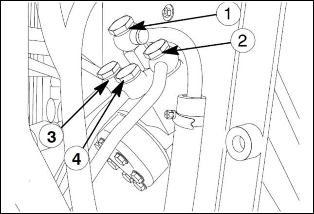
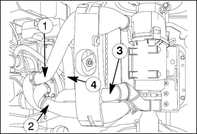
Engine Engine and crankcase 18. Remove two metal clamps (1) and the rigid pipe (2) of drawing oil from the transmission housing via lift pump. 19. Remove the electrical floor mat (1) 20. Remove the electrical connection from the brake fluid reservoir and take the brake fluid reservoir (1) from the bracket. 21. Disconnect the steering oil delivery and return hoses (1) and (2) Disconnect the steering cylinder lines (3) and (4) ANIL16TRO2597AA 16 ANIL16TRO2598AA 17 ANIL16TRO2599AA 18 ANIL16TRO2600AA 19 48064955 19/12/2016 10.1 [10.001] / 7

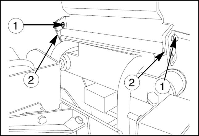
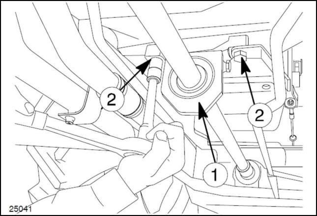
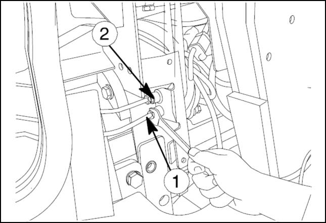
Engine Engine and crankcase 22. Remove two bolts (1) securing the rear hood to the gearbox. 23. Remove two bolts (1) securing the rear hood to the bonnet support. 24. Disconnect the delivery (1) and return lines (2) to the power steering cylinders. 25. Disconnect rear brakes oil distribution connection pipes (1) and (2) ANIL16TRO2601AA 20 ANIL16TRO2602AA 21 ANIL16TRO2603AA 22 ANIL16TRO2604AA 23 48064955 19/12/2016 10.1 [10.001] / 8
reading. Please Click Here. Then Get COMPLETE IfNOTEMANUAL.NOWAITING:thereisnoresponse to click on the link above, please download the PDF document first and then clickonit.

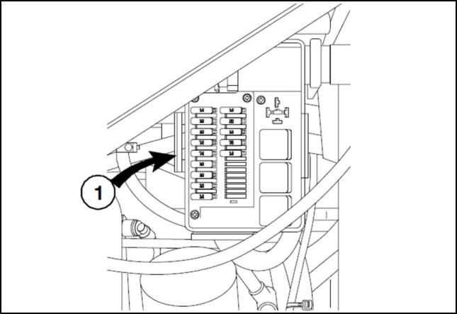
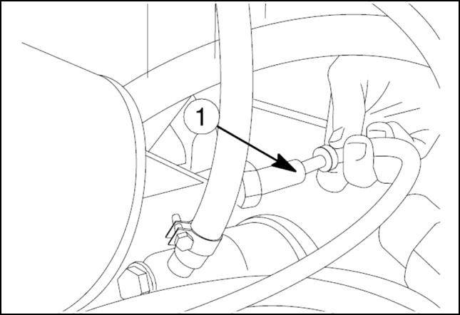
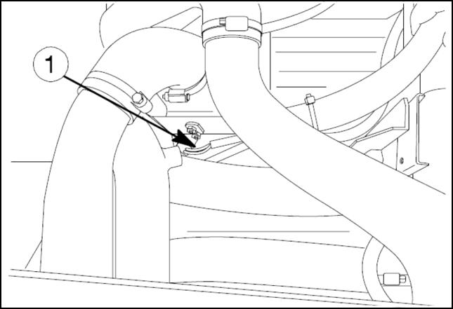
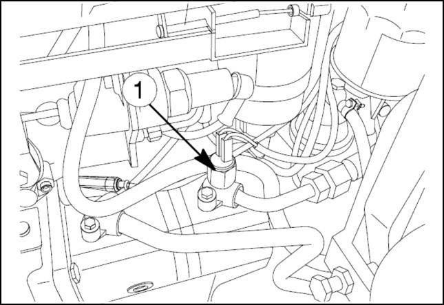
Engine Engine and crankcase 26. Remove the fuse box (1) from the bonnet support. 27. Remove the electrical oil pressure switch (1) 28. Remove the electrical connections of coolant temper ature sender (1) 29. Remove the electrical connection hydrostatic steering pump oil pressure switch (1) ANIL16TRO2605AA 24 ANIL16TRO2606AA 25 ANIL16TRO2607AA 26 ANIL16TRO2608AA 27 48064955 19/12/2016 10.1 [10.001] / 9
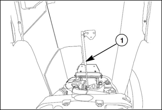
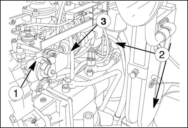
Engine Engine and crankcase 30. Remove the electrical connection of pump cut out so lenoid sender (1) 31. Remove the retaining bolts (1) and (2) for the support. Remove the retaining nut (3) and detach the throttle control tie rod connected to the injection pump. Remove the hand and foot throttle cables complete with their support (4) 32. Disconnect the electrical connection (1) between the cab and the engine. 33. Disconnect the electrical connections from starter mo tor (1) . ANIL16TRO2609AA 28 ANIL16TRO2610AA 29 ANIL16TRO2611AA 30 ANIL16TRO2612AA 31 48064955 19/12/2016 10.1 [10.001] / 10

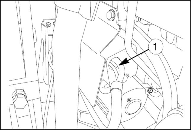
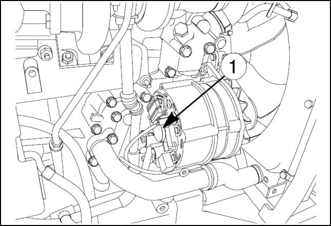
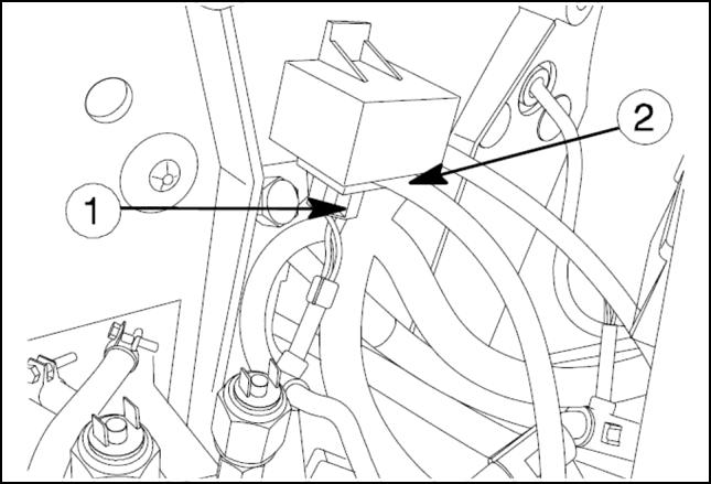
Engine Engine and crankcase 34. Disconnect the electrical connections from alternator (1) 35. Disconnect the electrical connection of water in fuel sensor (1) 36. Remove the electrical connection of air filter clogging sensor (1) 37. Remove the two connectors (1) and (2) for the heater relay. ANIL16TRO2613AA 32 ANIL16TRO2614AA 33 ANIL16TRO2615AA 34 ANIL16TRO2616AA 35 48064955 19/12/2016 10.1 [10.001] / 11

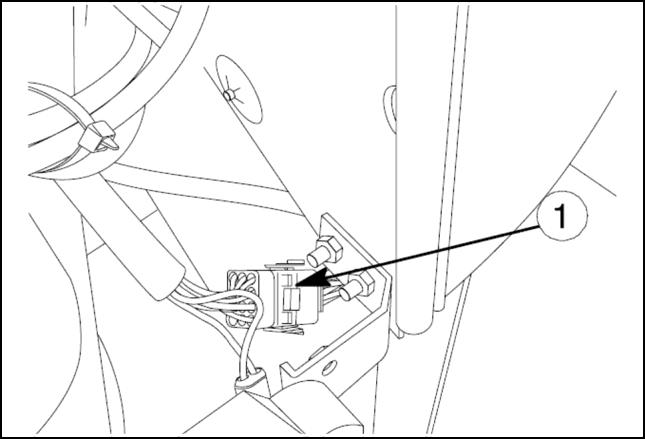
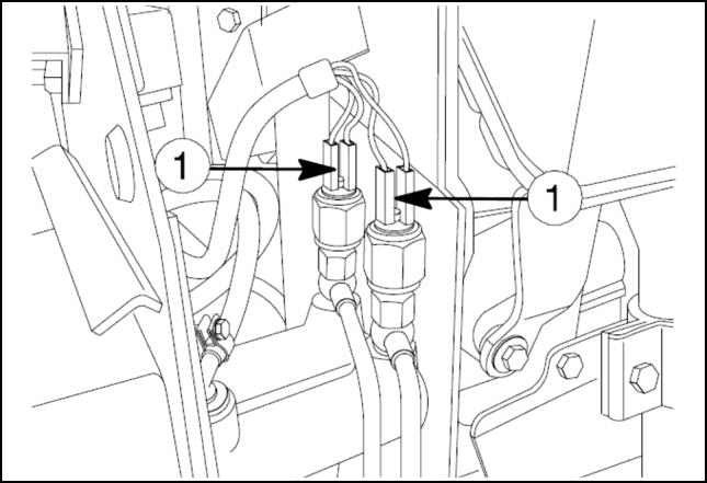
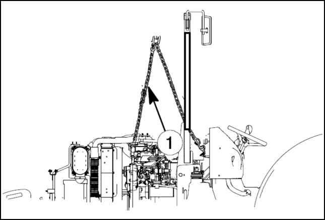
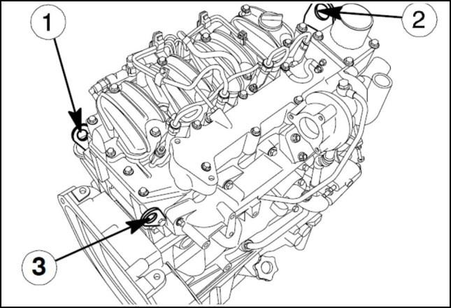
Engine Engine and crankcase 38. Remove the two connectors of the brake lights switch (1) 39. Loosen the corresponding retaining clamps and ex tract the pipes (1) , (2) , (3) and (4) 40. Hitch the engine to the hoist with the chains (1) an choring it to the attachments on the engine. 41. Engine lifting points are shown at image 39 ANIL16TRO2617AA 36 ANIL16TRO2618AA 37 ANIL16TRO2619AA 38 ANIL16TRO2620AA 39 48064955 19/12/2016 10.1 [10.001] / 12
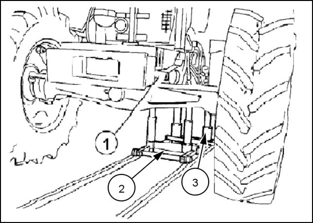
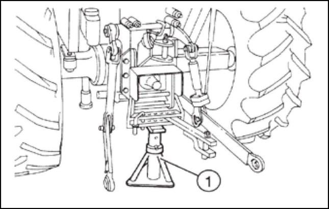
Engine Engine and crankcase 42. Position two wedges (1) on the front axle to prevent any movement of the engine about the axle pivot. Position the tractor dismantling stand , so that the fixed support (3) is under the rear transmission housing in the area of the engine coupling flange and the mobile support (2) under the engine in the area of the flange attached to the transmission housing. 43. Position another mobile stand under the front ballast carrier to prevent any possibility of the engine turning or tipping forwards when the transmission housing is removed. 44. Interpose wooden blocks (1) between the stands and the tractor, and turn the stand height adjustment screws to bring the blocks (1) into contact with the tractor. 45. Position a fixed stand (1) under the draw bar support and pull on the hand brake. BRAG12TRALL0080 40 BRAG12TRALL0081 41 LAIL11TL1134A0A 42 48064955 19/12/2016 10.1 [10.001] / 13