LUBRICATION SYSTEM OPERATION
DIESEL ENGINE
LUBRICATION SYSTEM OPERATION A ROCKER ARMS
B
C CRANKSHAFT MAIN
MAIN OIL L GALLEY OIL PRESSURE SENSOR
ROCKER ARM SHAFT
BEARINGS
K D CAMSHAFT
OIL FILTER J
BEARINGS
CONNECTING I ROD JOURNAL
IDLER
E GEAR
BUSHING
H INJECTION PUMP
RESERVOIR INTAKE SCREEN G PUMP PRESSURE OIL
OIL PUMP F
PRESSURE FREE OIL
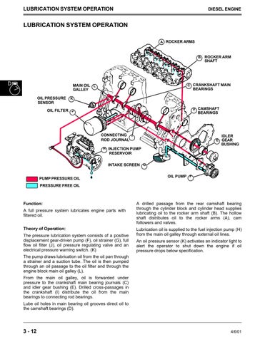
Function: A full pressure system lubricates engine parts with filtered oil. Theory of Operation: The pressure lubrication system consists of a positive displacement gear-driven pump (F), oil strainer (G), full flow oil filter (J), oil pressure regulating valve and an electrical pressure warning switch. (K)
A drilled passage from the rear camshaft bearing through the cylinder block and cylinder head supplies lubricating oil to the rocker arm shaft (B). The hollow shaft distributes oil to the rocker arms (A), cam followers and valves. Lubrication oil is supplied to the fuel injection pump (H) from the main oil galley through external oil lines. An oil pressure sensor (K) activates an indicator light to alert the operator to shut down the engine if oil pressure drops below specification.
The pump draws lubrication oil from the oil pan through a strainer and a suction tube. The oil is then pumped through an oil passage to the oil filter and through the engine block main oil galley (L). From the main oil galley, oil is forwarded under pressure to the crankshaft main bearing journals (C) and idler gear bushing (E). Drilled cross-passages in the crankshaft (I) distribute the oil from the main bearings to connecting rod bearings. Lube oil holes in main bearing oil grooves direct oil to the camshaft bearings (D).
3 - 12
4/6/01


