5 minute read
TROUBLESHOOTING CHART


A
B
Advertisement
M91893
Results:
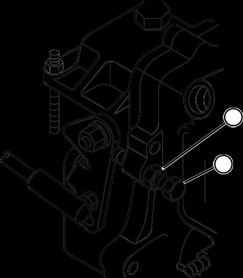
• If the slow idle rpm is not according to specifications, loosen the nut (A) and turn the slow idle stop screw (B) clockwise to increase the engine speed, or counterclockwise to decrease the engine speed until the slow idle speed is correct.
After adjustment, tighten the nut.
VALVE CLEARANCE ADJUSTMENT
Reason:
To be sure the valves are fully opening and closing at the correct time, and not wearing the valve train unnecessarily.
Equipment:
• Feeler Gauge • 10 mm End Wrench • Flat Blade Screwdriver • 17 mm Wrench
Procedure:
1. The engine must be cool (room temperature) before the valve clearance is checked. 2. Be sure ignition key is OFF before attempting to turn engine by hand. 3. Open the hood and remove the engine side covers. 4. Remove the rocker arm cover. (See “ROCKER
ARM COVER REMOVAL AND INSTALLATION”).
1
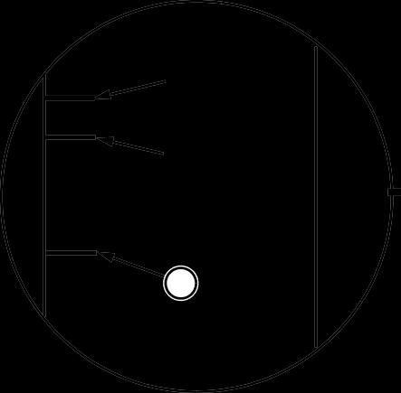
14° BTDC
12° BTDC
A
Flywheel Timing Marks Direction of Engine Rotation
Center Line
5. Locate the inspection hole in right side of the transmission tunnel. The flywheel can be seen inside the inspection hole.
NOTE: “Top Dead Center (TDC)” is when the piston is at it’s highest point of travel in the cylinder on the compression stroke. Number one cylinder is located at rear of engine (flywheel side).
6. Turn the crankshaft pulley while watching the flywheel inside the inspection hole. Align the number one TDC mark (A) on the flywheel with the pointer on the tunnel.
NOTE: When top dead center is reached, the rocker arms for that cylinder will be motionless as the crankshaft is rotated. If rocker arms are still moving when TDC is approached, rotate crankshaft one full revolution and try again.
7. Try to move rocker arms and/or push rods for No. 1 cylinder: • If the rocker arms and push rods are loose, the piston is at TDC on the compression stroke. Go to step 8. • If the rocker arms and/or push rods are not loose, rotate the flywheel one revolution (360°), and recheck the rocker arms and push rods.
A C

B
MX1194
8. Slide a feeler gauge between the valve cap (A) and rocker arm to measure the clearance.
9. To adjust the valves, loosen the lock nut (B) and turn the adjusting screw (C) until the blade of the feeler gauge can be inserted between the rocker arm and valve cap. Hold the adjusting screw while tightening the lock nut. 10. Recheck the valve clearance after tightening the lock nut.

T6105BF
Specification: Valve Clearance . 0.15 – 0.25 mm (0.006 – 0.010 in.)
Normal Not Normal
11. Check that the valve cap on the valve stem remained seated on the valve and inside the valve spring retainer. 12. Turn the crankshaft pulley counter clockwise (as viewed from operator’s seat or flywheel end) approximately 2/3 of a revolution (240°) while watching the observation hole for the number three timing mark.
Reason:
To determine proper side clearance between the crankshaft and the connecting rod.
13. Check that the rocker arms and push rods for cylinder number three are loose. 14. Repeat steps 7 – 13 for number three cylinder. 15. Repeat steps 7 – 11 for number two cylinder. 16. Replace the rocker arm cover, air cleaner bracket and housing, and the muffler. 17. Replace the engine side covers and hood.
CONNECTING ROD SIDE PLAY CHECK
Equipment:
• Feeler Gauge
NOTE: The engine must be removed from the tractor to perform this test.
Procedure:
1. Remove the oil pan, crankcase extension, oil pickup, and balancer assembly. 2. Insert a feeler gauge, according to specifications, between the connecting rod cap and the crankshaft.

M82116A
3. Connecting rod side play is 0.2 - 0.4 mm (0.008 -
0.016 in.).
Results:
• If the side play exceeds specification, replace the bearing inserts or the connecting rod.
CONNECTING ROD BEARING CLEARANCE CHECK
Reason:
To measure oil clearance between connecting rod bearing and crankshaft journal.
Equipment:
• PLASTIGAGE®
NOTE: The engine must be removed from the tractor to perform this procedure.
Procedure:
1. Remove the oil pan, and oil pickup.
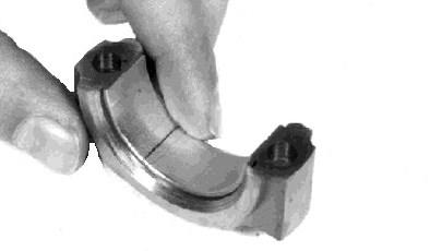
IMPORTANT: The connecting rod caps must be installed on the same connecting rod and in the same direction to prevent crankshaft and connecting rod damage.
2. Remove the connecting rod cap. 3. Wipe oil from the bearing insert and the crankshaft journal. 4. Put a piece of PLASTIGAGE® (A), or an equivalent, along the full length of the bearing insert approximately 6 mm (0.25 in.) off center.

5. Turn the crankshaft approximately 30° from bottom dead center. 6. Install the connecting rod end cap and original rod bolts. Tighten the rod bolts to specification.
A
M35351 NOTE: The flattened PLASTIGAGE (B) will be found on either the bearing insert or crankshaft journal.
8. Use the graduation marks on the envelope (C) to compare the width of the flattened PLASTIGAGE at its widest point. The number within the graduation marks indicates the bearing clearance in inches or millimeters depending on which side of the envelope is used.
9. Measure the connecting rod bearing oil clearance.
C
B
M82117A
Specification: Connecting Rod Bearing Oil Clearance 4200.....................0.04 - 0.09 mm (0.002 - 0.004 in.)
Wear Limit ................................ 0.25 mm (0.010 in.) 4300, 4400 . . . . . 0.04 - 0.07 mm (0.002 - 0.003 in.)
Wear Limit ................................ 0.16 mm (0.006 in.)
Result:
• If the clearance exceeds the wear limit specification, replace the bearing inserts. 10. Remove the PLASTIGAGE® .
PLASTIGAGE® is a registered trademark of the
DANA Corporation.


