
Document Title: Description FunctionGroup: 500 Information Type: Service Information Date: 2014/7/7 0
Articulated hauler A30C is equipped with a compressed air hydraulic brake system affecting the service brake on all wheels.
Operation of the service brake is achieved through a dual circuit service brake (foot brake) valve. The valve regulates the brake pressure directly on the tractor unit and on the load unit by way of a relay valve to the compressed air hydraulic brake units. The brake units have a diaphragm affected by the compressed air. The diaphragm is attached to a piston rod. The piston rod transfers the force to a piston pressing on the brake fluid.The area differential between the diaphragm and the piston is large, resulting in a pressure increase on the brake fluid. The brake fluid acts on the pistons in the brake calipers.
The parking brake acts by compressed air on the propeller shaft. It is applied by spring force and is released with compressed air. The service brake and parking brake are disc type brakes with one or more brake calipersperdisc.
The engine is equipped with a direct drive one cylinder water cooled compressor and separate unloading pressure regulator for supply of compressed air. A30C has two accumulators on the tractor unit and one accumulator on the load unit for storing compressed air.
The longitudinal differential is engaged when the parking brake is applied in order to allow the parking brake to act on several wheels simultaneously.
Profile: Description
The four compressed air hydraulic units, two for the front axle and two for the load unit, have reservoirs for brake fluid. The load unit reservoir tank is located on the brake unit and separate witha hose connectionto the tractorunit.
Service Information

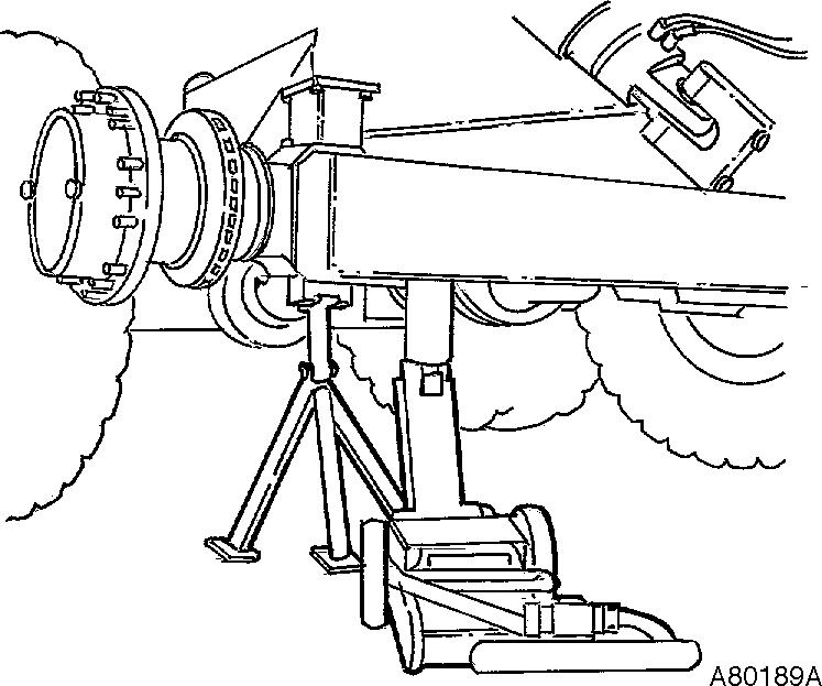
Service Information Document Title: Brake discs, changing FunctionGroup: 510 Information Type: Service Information Date: 2014/7/7 0 Profile: Brake discs, changing Op nbr 51102 E 1666 Hublifting device E 1667 Liftingdevice Wheel forklift or equivalent equipment 11668004 Sleeve(hub nut ) Garage jack 10 ton (22 050 lbs.) Torque wrench0 1000 Nm (0 738 ft.lbs) Removing 1. Park the machine on a firm and level surface (service position) and block at least one of the wheels. 2. Remove the wheel using a wheel forklift or equivalent equipment, see fig. Figure 1 Wheel forklift 3. Secure witha support stand. Position the axle so that the oil does not drain from the axle housing . Drain the oil out of the huband axle center through the plug in thehub.

8. Fot guide pins M12xM120 in twoholes.Use puller bolts M16x60. Pulloutthe planetary retainer on the guide pins and lower. Figure 3
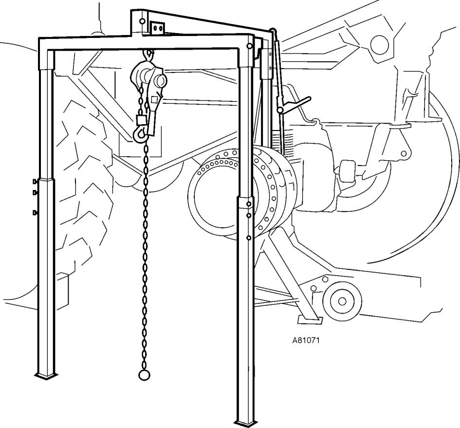
4. Remove brake shields, brake pads, brake lines and brake caliper. Plug brake pipes andhoses. 5. Remove the bolts forthe planetary retainer. Figure 2 Lifting of axle, bogie 6. Set up E 1666,Hubliftingdevice. 7. Use thread protectors 10x 35 mm to make sure that the threads in the hub are not damaged by the pullerbolts.
10.
9. Remove the retaining ring and the sun gear on the drive axle. Leave the axle inplace. Remove the lockingring and the lock washer on theaxle.
15.
11. Loosen and remove hub nutwith sleeve 11668004. Figure 4 12. Secure the ring gear with two bolts and two large washers so that it does not fall out of thehub.
14.
13.
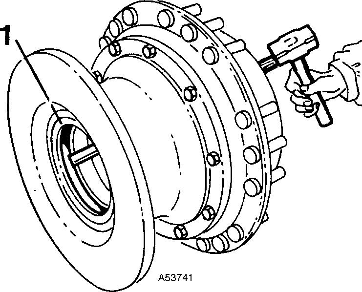
Figure 5 Hookup the hub with E 1667 Hublifting device and lift away hub complete with ring gear, see fig. Figure 6 Place the hub on the floor with the brake disc up. Remove the old brake disc and replace witha new disc.Fit new spring washers.
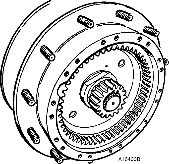
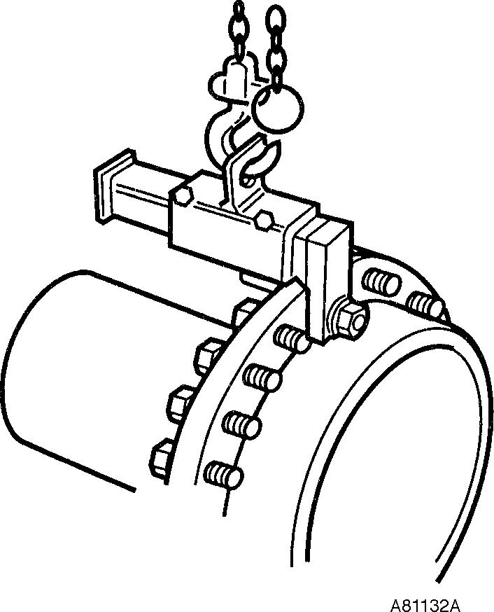
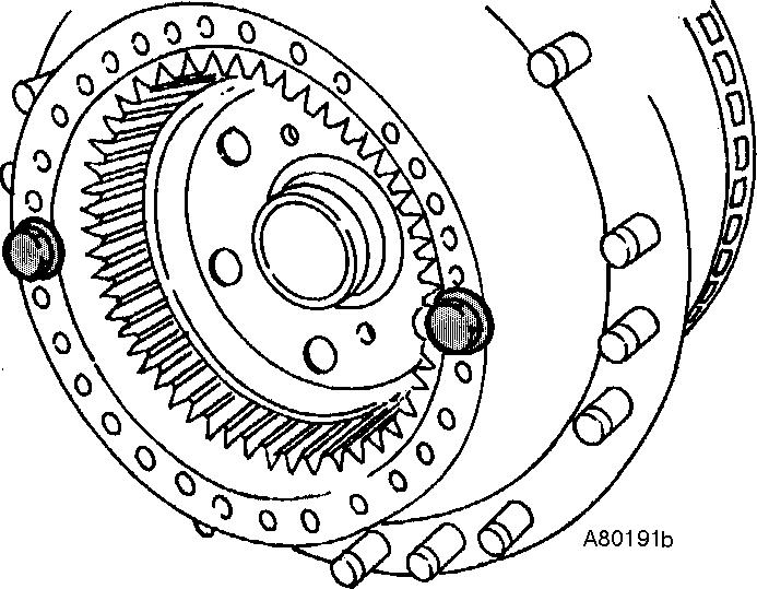
Figure 8 Adjust the indicator pin on sleeve 11668004sothat it corresponds to one of the bolt holes in thehub. Tighten hub nut until the indicatorpin reaches the nexthole (12°)inthehub. Mount the lock washer and retainingring.
23.
21.
CAUTION Never loosen the hub nutto fit the lock washer. The lockwasher is available in two different types. Fit sun gear with retaining ring. Clean the planetary carrier and hub.Apply new sealant. Mount the planetary carrier with a few bolts. Fit and tap in the guide pins. Torque to 110 Nm (81.1 ft.lbs).
20.
19.
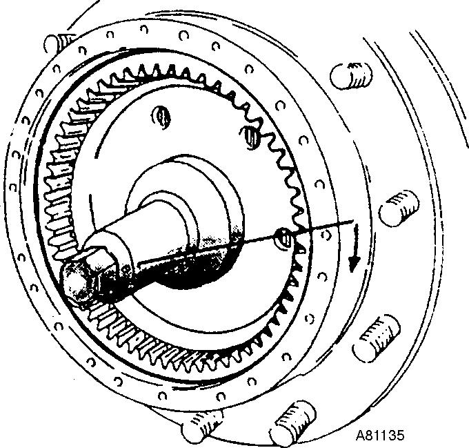
Figure 7 Lift up the hub complete with ring gear. Torque the hubwith 600 800 Nm (442.6 590 ft.lbs)using sleeve11668004. Turn the hub 4 5 turns and loosen hub nut 1/2 turn. Torque the hubnut to 300 Nm (221.3ft.lbs).
16. Changeseal. Also replace the wear ring if there is noticeablewear.
22.
24.
17.
25.
26.
18.

27. Torque brake disc to 310 Nm(228.7 ft.lbs). 28. Mount brake caliper and torque to 550 Nm(405.7 ft.lbs). Connect brake lines andhoses. Figure 9 29. Mount the brake shoe. Lock the bolts using medium type locking fluid.Torque to240 Nm(177.0 ft.lbs). Bleed brake system. 30. Mount the brake shields and wheel. Torque wheel nuts to 800 Nm (590ft.lbs). 31. Check oil level in axle. Fillif needed. Remove wheel blocks. 32. Check functions.
Thank you very much for reading. This is part of the demo page. GET ClickMORE:HereBUY NOW SystemDescription,Instructions,System,HydraulicSettingFunctionalElectricalAndmore ……