Service Information Document Title: Description D6D FunctionGroup: 200 Information Type: Service Information Date: 2014/5/8 0 Profile: EXC, EW200B [GB] Description D6D The D6D engine is a straight six cylinder,direct injected four stroke diesel engine, with electronically controlled fuel injection EMS (EngineManagement System). The engine meets the emission requirements according to EURO2. The engine number is stamped on the name plate and on the engine block'sright side. Model and serial number must always be indicated when ordering spare parts.

Service ManualInformation Document Title: Engine, removal FunctionGroup: 210 Information Type: Service Information Date: 2014/5/8 0 Profile: EXC, EW200B [GB] Engine, removal Op nbr 210-01 Liftinglinks, min. 1000 kg Hose with valve WARNING Risk of burns - stop the diesel engine and allow it to cool down before starting any work. NOTE! Clamps that secure hoses and wiring should be removed and replaced when installing. 1. Turn off the electric powerwith the battery disconnector. 2. Figure Superstructure1 1. Cover 2. Cover Remove the covers over the diesel engine. 3. Remove the protective plates under the engine. 4. Connect a hose with valve (tool equipment) and drain the coolant from the radiator into a clean container.Filled radiator contains approx.22 litres. 5. Connect a hose with valve (tool equipment) and drain the hydraulic oil from thehydraulic oil tank into a clean container. Filled tank contains approx. 190 litres. 6. Disconnect the connectionsto the sight glass forthe hydraulic oil tank. Plug and mark. 7. Remove the hoodopener.

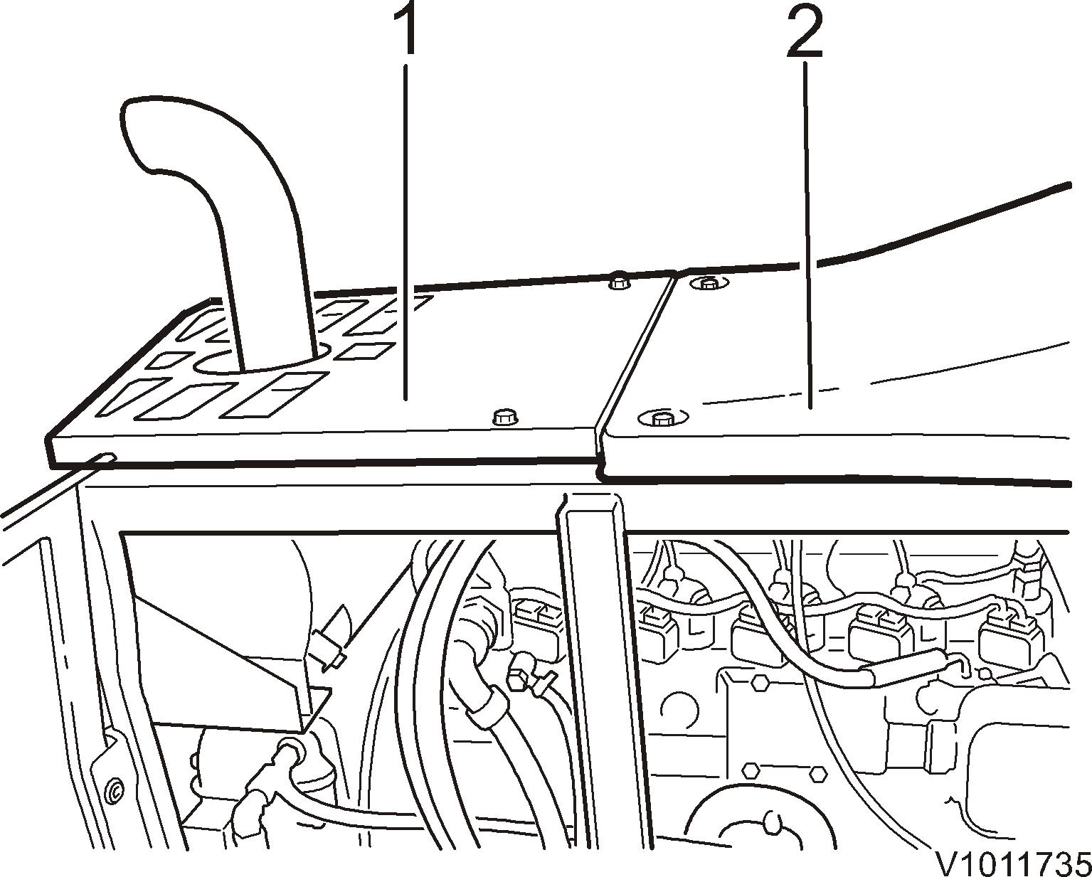
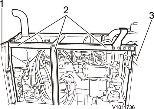
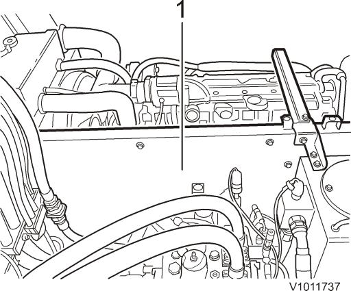
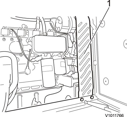
8. Figure Framework2 1. Cover 2. Framework 3. DisconnectCoverthe outer framework and lift away the frame with the covers. 9. Figure Engine/hydraulic3 compartment 1. Intermediate wall 10. Figure Engine/hydraulic4 compartment 1. Framework Remove the remaining framework.

11. Figure Radiator/engine5 1. Cooling hose .6 Cooling hose 2. Cooling hose 7.Cooling hose 3. Cooling hose 8. Cabling 4. Intercooler hose 9.Induction hose to turbo 5. AC compressor 10.Inductionhose toturbo Disconnect the engine from the coolinghoses. Remove the upper intercooler hose and disconnectthe lower from the Disconnectengine. the engine from the inductionshoses for the turbo. Disconnect (ifinstalled) the AC compressor from the engine, and remove the Vee belts. NOTE! Do NOT loosen the hoses from the compressor. 12. Figure Exhaust6pipe/muffler 1. Exhaust clamp Loosen the exhaustclamp.
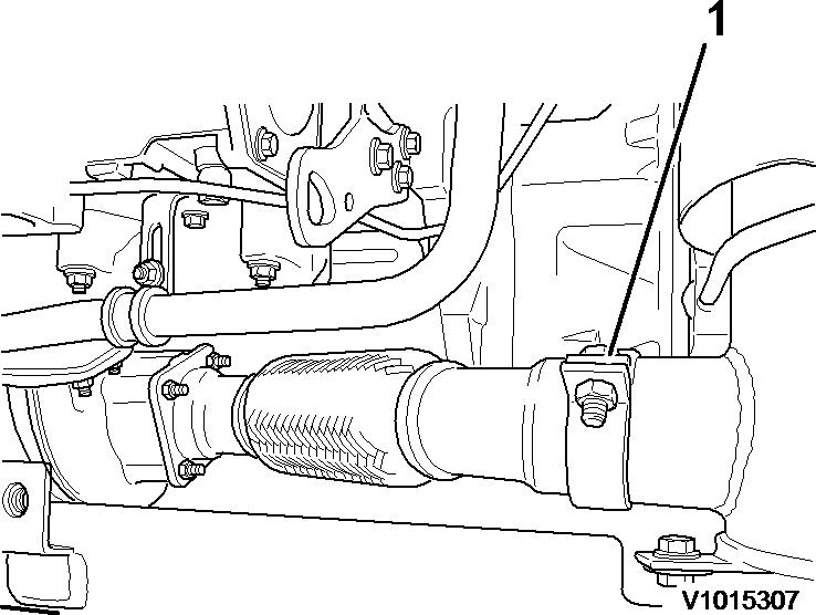

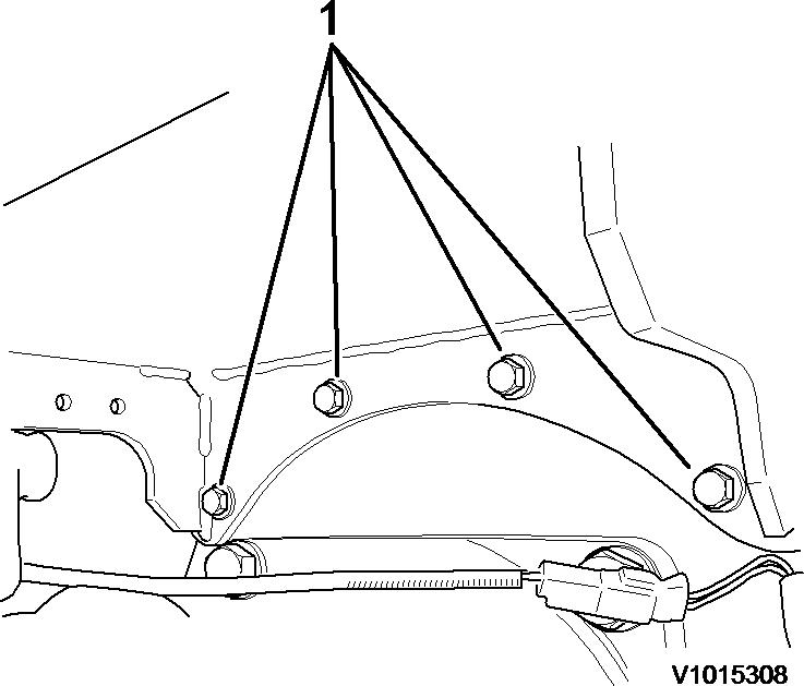
13. Figure Underside7 mufflerbracket 1. Attachingbolts Remove the attachingbolts for the muffler bracket and remove the muffler and bracket. 14. Figure 8 Coverplate overstarter motor 1. Cover plate Remove the cover plate over the starter motor. 15. Figure Engine/Starter9 motor

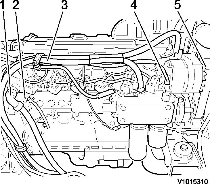
1. Ground connection 2. Cabling 3. DisconnectCablingthecabling for the starter motor and ground connection. 16. Figure 10 Fan pump 1. Hydraulic hose 2. Hydraulic hose Disconnect the fanpump from the hydraulic oil hoses. Plug and mark up. (Onlyinstalled if machine is equipped with hydraulic coolingfan.) 17. Figure Engine,11side view 1. Cabling 2. Fuel line 3. Cooling hose 4. Cabling 5. Fuel line Disconnect the engine from the cabling,fuel lines and cooling hose. Plug and mark up. 18. Remove the servo pump accordingto 914 Servo pump, removal 19. Remove the workingpump according to 913 Pump, removal.
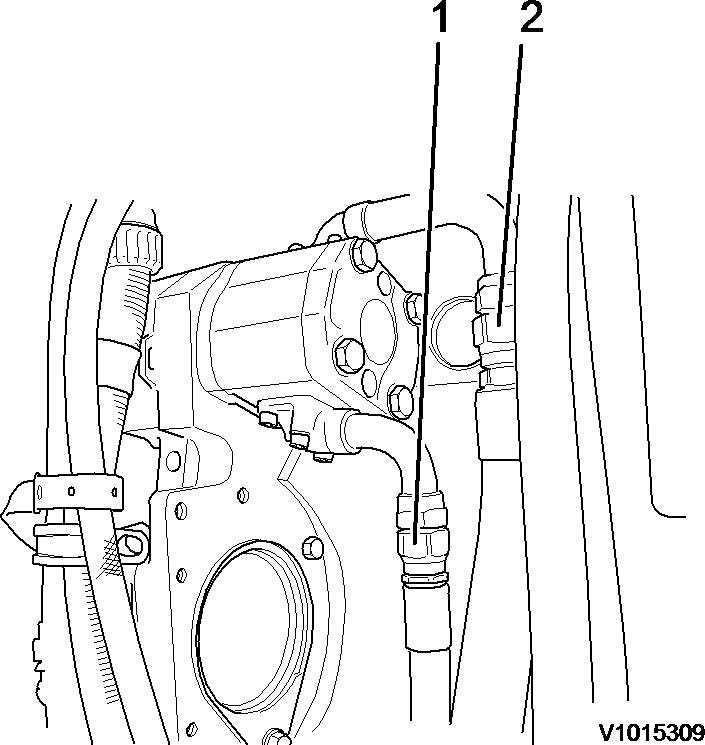
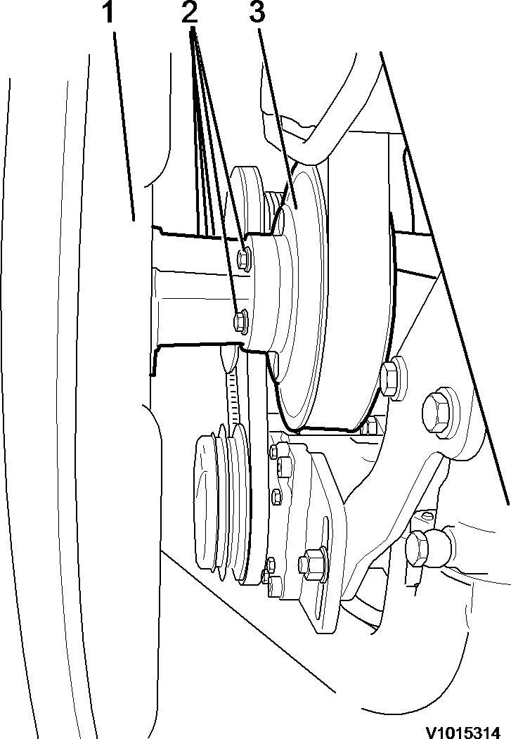
20. Figure Hydraulic12 cooling fan 1. Elbow nipple If hydraulicallydriven coolingfan (option):Remove the elbow nipple on the coolingfan and plug. 21. Figure 13 Belt drivencooling fan 1. Cooling fan 2. Attachingbolts 3. Belt pulley If belt driven coolingfan: Remove the attaching bolts for the belt pulley. Remove the coolingfan.

22. Figure 14 Lifting links on engine 1. Liftinglinks 2. Liftingeyes Connect the liftinglinks in the engine's lifting eyes and in a lifting device. Tighten up the lifting links. 23. Remove the bolted joints for the engine mounts. 24. Lift out the engine carefully. 25. Place the engine on stable supports.
Service Information Document Title: Engine, installation FunctionGroup: 210 Information Type: Service Information Date: 2014/5/8 0 Profile: EXC, EW200B [GB] Engine, installation Op nbr 210 02 14360000 Vacuumpump Liftinglinks, min. 1500 kg 1. Lift in the engine carefully. 2. Fit the bolted joints for the engine mounts. Tightening torque: 687 ±68Nm. 3. Figure 1 Belt drivencooling fan 1. Cooling fan 2. Attachingbolts 3. Belt pulley If belt driven coolingfan: Fit the cooling fan and fit the attachingbolts for the belt pulley.
4. Figure Hydraulically2 driven cooling fan 1. Elbow nipple If hydraulicallydriven coolingfan (option):Fit the elbow nipple on the coolingfan. 5. Fit the workingpump according to913 Pump, installation 6. Fit the servo pump accordingto 914 Servo pump, installing 7. Figure Engine,3side view 1. Cabling 2. Fuel line 3. Cooling hose 4. Cabling 5. Fuel line Fit cabling,fuel lines and cooling hose.
8. Figure 4 Fan pump 1. Hydraulic hose 2. Hydraulic hose Fit the fan pump's hydraulic oil hoses. (Onlyinstalled ifmachine is equipped withhydraulically driven coolingfan.) 9. Figure Engine/starter5 motor 1. Ground connection 2. Cabling 3. Cabling Fit the cablingfor the starter motor and the ground connection.
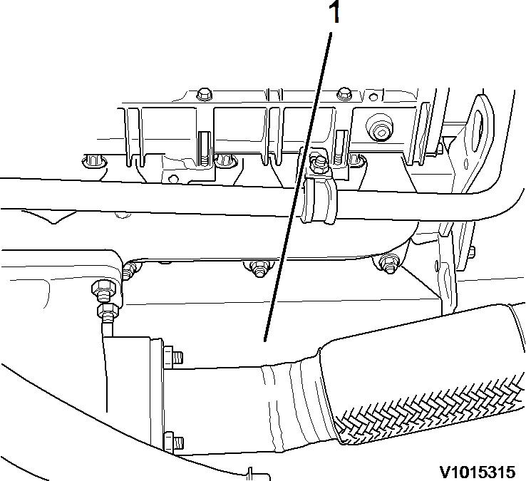
10. Figure 6 Coverplate overstarter motor 1. Cover plate Fit the cover plate over the starter motor. 11. Figure Underside7 mufflerbracket 1. Underside muffler bracket Fit the muffler bracket with the muffler. Fit the attachingbolts for the bracket. 12. Figure Exhaust8pipe/muffler 1. Exhaust clamp
Fit the exhaustclamp. 13. Figure Radiator/engine9 1.Cooling hose .6 Cooling hose 2.Cooling hose 7.Cooling hose 3.Cooling hose 8.Cabling 4.Intercooler hose 9.Induction hose to turbo 5.AC compressor 10.Inductionhose to turbo Fit the Vee belts and the AC compressor. Fit the upper and lower intercooler hose. Fit the coolinghoses. Fit the inductionhoses for the turbo. 14. Figure Engine/hydraulic10 compartment 1. Framework Fit the inner framework.
15. Figure Engine/hydraulic11 compartment 1. Intermediate wall 16. Figure Framework12 1. Cover 2. Framework 3. Cover Fit the covers and the outer framework. 17. Fit the hoodopener. 18. Fit the connectionsforthe sight glass for the hydraulic oil level. 19. Fill the hydraulic oil tank with hydraulic oil. The tank's capacityis approx. 190 litres.

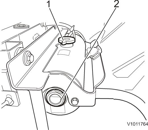
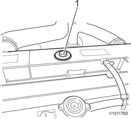
20. Figure Expansion13 tank 1. Cap 2. Sight glass Remove the cap and fill coolantin the expansion tank until the level is in the middle of the sight glass. 21. Figure Radiator14 1. Fillingpoint Fill completely in the radiator's fillingpoint. 22. Check oil level in theengine. Fill ifneeded. 23. Fit the protective plates under the engine.
24. Figure Superstructure15 1. Cover 2. Cover Fit the covers over the diesel engine. 25. Start the diesel engine, place thedigging equipment in position A, see 091 Servicepositions 26. Stop thediesel engine and checkthe hydraulic oil level, top up if needed. Check the coolant level, top up if needed.
Service Information Document Title: Cylinder head, description FunctionGroup: 211 Information Type: Service Information Date: 2014/5/8 0 Profile: EXC, EW200B [GB] Cylinder head, description
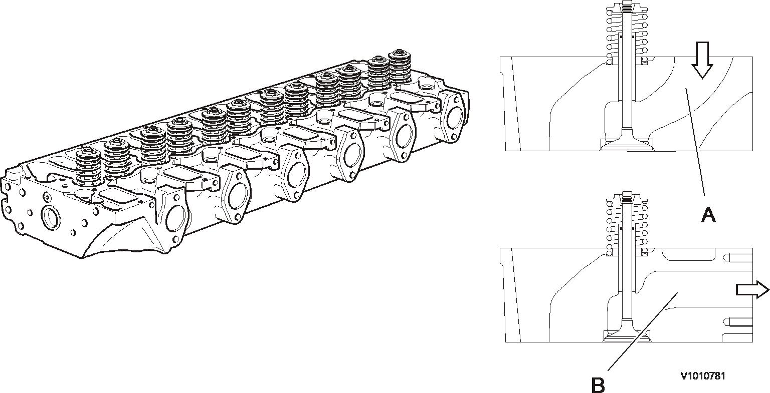
Figure 1
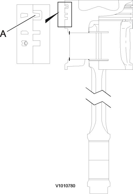
The cylinder head is made of cast iron and is common for all cylinders. The induction air enters vertically (A) and the exhausts leave horizontally (B). Inlets and exhaust outlets are located on the same side of the cylinder block. On order for the engine to fulfill governing emission standards, there are 3 cylinder head gaskets of different thicknesses between the cylinder head and the piston.
The pistons are made of special alloy aluminium. The piston's combustion compartment has a somewhat off center (eccentric)position in relation to the piston pin.
The first piston ring has an asymmetric cross section area (A). The cross section area for piston ring number two (compression ring) is tapered. When installing the piston rings, the marking TOP by the opening in the rings must face up. The third ring is an oil ring with bevelled edge. Figure 1
The pistons are provided with 3 piston rings. The first ring has a ring carrier made of cast iron. The piston is cooled with oil sprayed up on the inside of the piston top. The piston coolingnozzles are made of plastic and are mounted in the cylinder head by the main bearing positions.
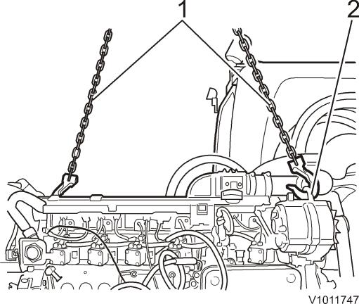
Service Information Document Title: Pistons, description FunctionGroup: 213 Information Type: Service Information Date: 2014/5/8 0
Profile: D6E Engine
EXC, EW200B [GB] Pistons, description
The new compressed tapered shape enables the valves to turn easily despite loading.
Profile: EW200B [GB]
Service Information Document Title: Valve mechanism, description FunctionGroup: 214 Information Type: Service Information Date: 2014/5/8 0
EXC,
The engines are equipped with one inlet and one exhaust valve per cylinder. At the upper end of the valve guide, there's an O ring seal against the valve spindle to prevent major oil consumption and to reduce the amount of hydrocarbons in the exhausts.
Valve mechanism, description
The valves are rotated by the eccentric action of the rocker arms.
Rocker arm lubrication is part of the engine's force feed lubrication system. The oil is supplied via the tappets and push rods.
Service Information Document Title: Valves, adjusting FunctionGroup: 214 Information Type: Service Information Date: 2014/5/8 0 Profile: EXC, EW200B [GB] Valves, adjusting Op nbr 21412 1. Park the machine in a suitable service position, see 091 Servicepositions 2. Disconnect the batteries withthe battery disconnecting switch. 3. Remove the belt cover. Figure 1 Engine 1. Belt cover 4. Remove the bothcover hatches over the engine. Figure Superstructure2 1. Rear cover hatch 2. Front cover hatch 5. Remove the parallel stay.
Thank you very much for reading. This is part of the demo page. GET ClickInstructions,System,HydraulicMORE:SettingFunctionalDescription,ElectricalSystemAndmoreHereBUYNOW System And more……
Figure Superstructure3 1. Parallel stay 6. Loosen the oiltrap. Figure 4 Oil trap 1. Bolts 7. Loosen and remove the bolts for the valve cover. Remove the valvecover. Figure 5 Valve cover The figures show valve adjustment on a removed engine.
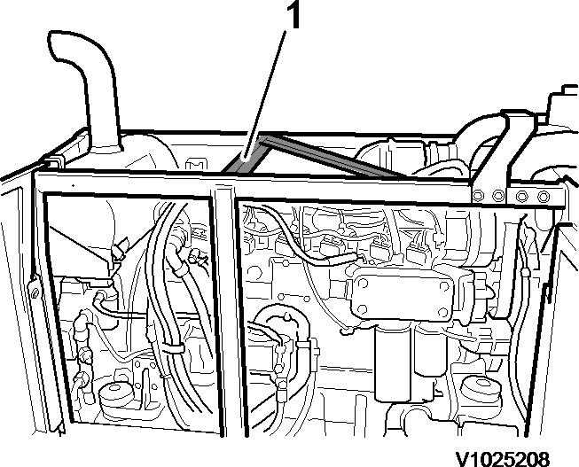
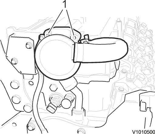
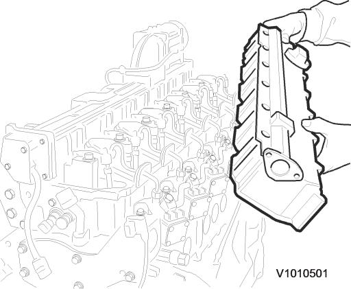
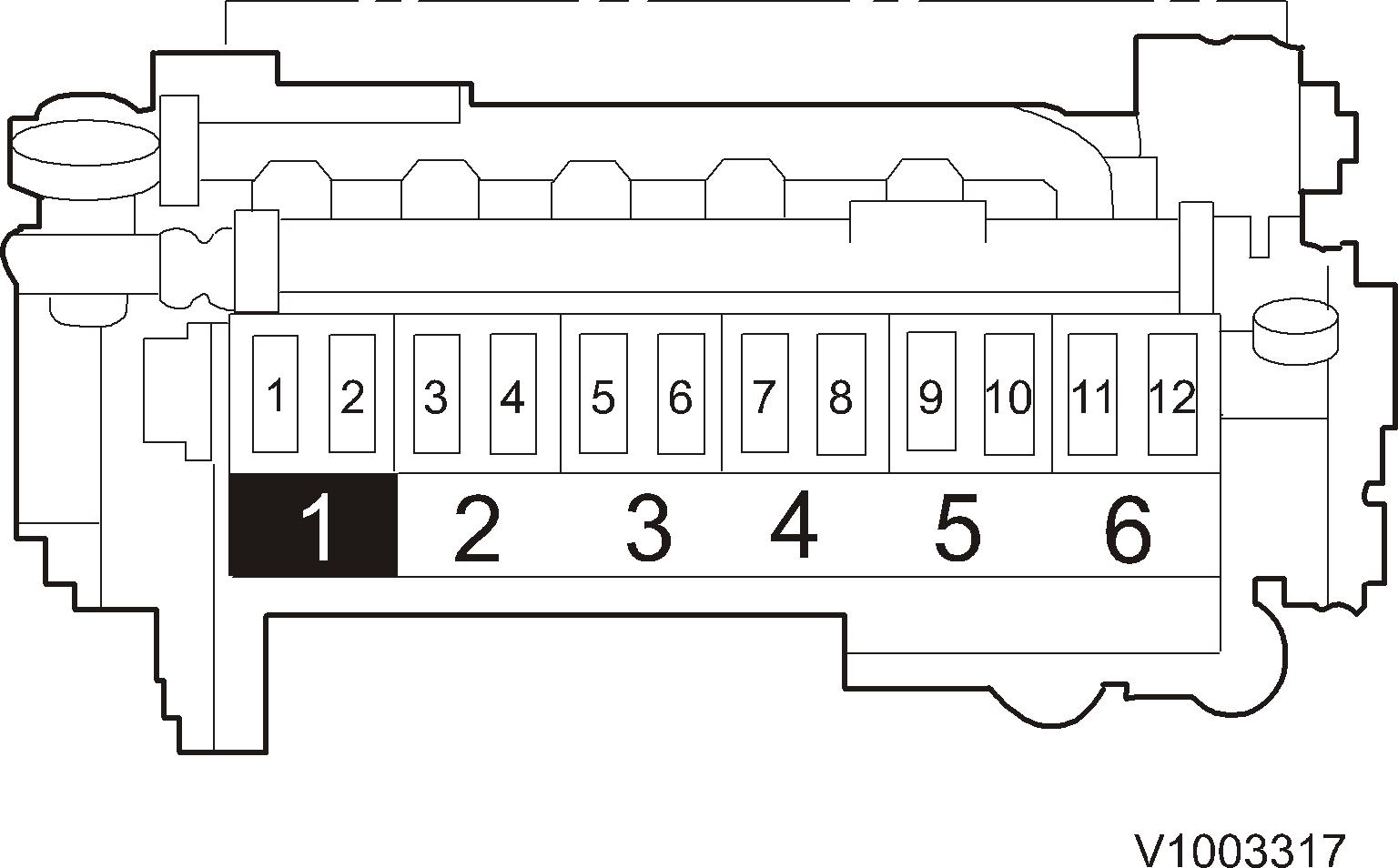
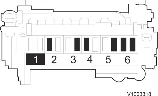
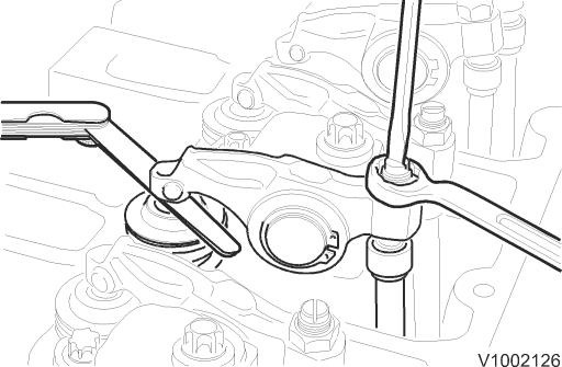
Figure 6 1,3, 5,7,9,11:exhaustvalve 2,4, 6,8,10,12:inlet valves 8. Rotate the engine with a fan blade untilthe valves on cylinder 1 rock (breakover). 9. Adjust the clearance for the valves marked withblack in the figure. Inlet valve:0.35 ±0.05 mm (0.014 ±0.0020 in) Exhaust valve:0.50 ±0.05 mm (0.020 ±0.0020 in) Figure 7 10. Tighten the locknut. Tightening torque: 20 Nm (14.7 lbfft) Check the adjustment onceagain with the feeler gauge. Figure Valves,8adjusting 11. Rotate the engine one full revolution until the valves on cylinder6 rock (break over).Adjust the clearance forthe valves marked withblack in the figure.