
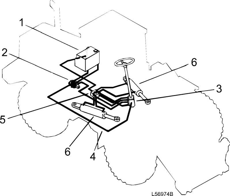
The steering system hydraulic pump, which is driven via the right power take off on the transmission, is a so called load sensing axial piston pump. The pump for the brake and servo systems is mounted in tandem with the steering pump. The working hydraulicsand the brake systems have the hydraulic oil tank in common.
Profile: Description
1. Hydraulic tank 2. Steering pump 3. Steering valve 4. Load sensing (LS) line 5. Valve block withanti cavitation valves and back up valve for return pressure 6. Steering cylinders
Theconditions.machine
The outlet ports on the steering valve are connected to the piston end of one of the steering cylinders and the piston rod end of the other steering cylinder. sensing hydrostatic steering system L90C
Figure 1 Load
The loader is provided with hydrostatic articulated frame steering consisting of pump, steering valve (ORBITROL) and two cylinders. The L120C also has a shift valve for disconnecting the piston rod end of the cylinders, during lighter steering canbe equipped with lever steering (CDC) and secondary steering.
Service Information Document Title: Description FunctionGroup: 600 Information Type: Service Information Date: 2014/5/27

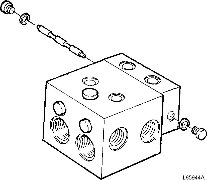
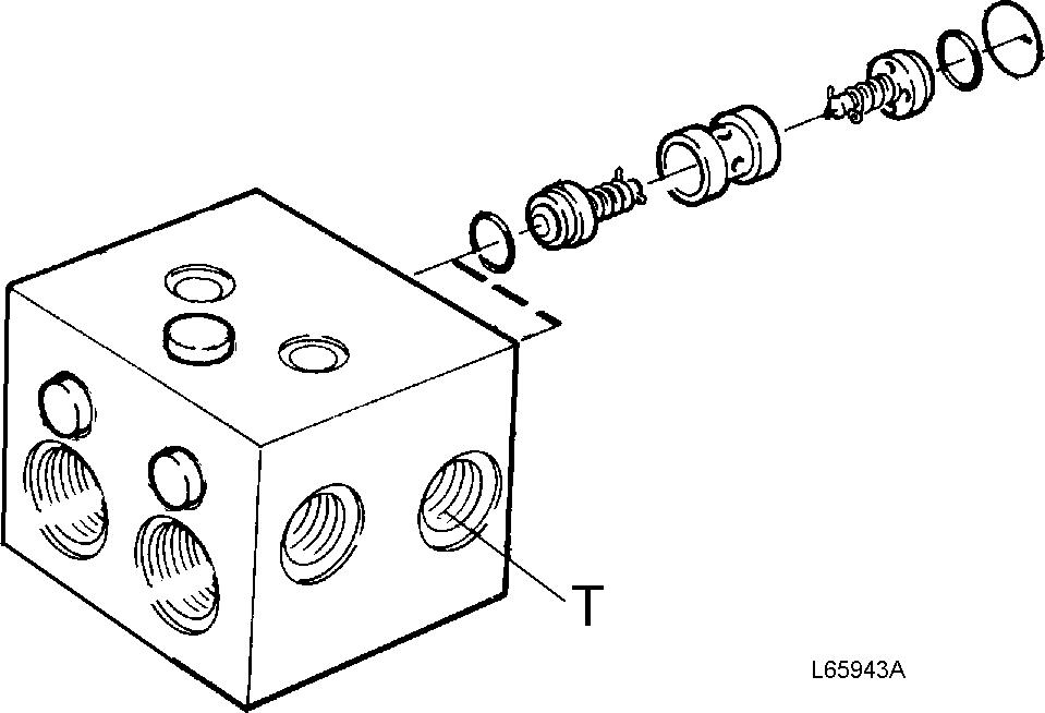
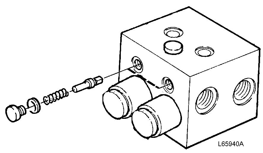
Service Information Document Title: Shift valve, reconditioning (removed) FunctionGroup: 645 Information Type: Service Information Date: 2014/5/27 Profile: Shift valve, reconditioning (removed) Op nbr 64578 1. Remove the unionsfor thetank connections(marked T on the valve). Figure 1 Shift valve 1 Valve housing 13 O ring 2 End plate 14 Poppet 3 Hexagon socket head bolt 15 Spring 4 Washer 16 Non return valve
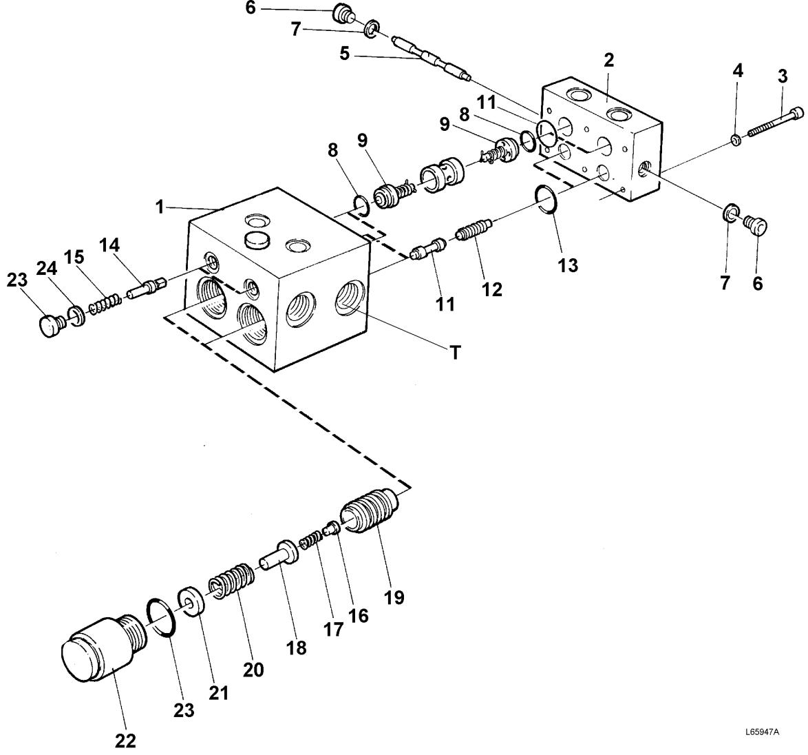
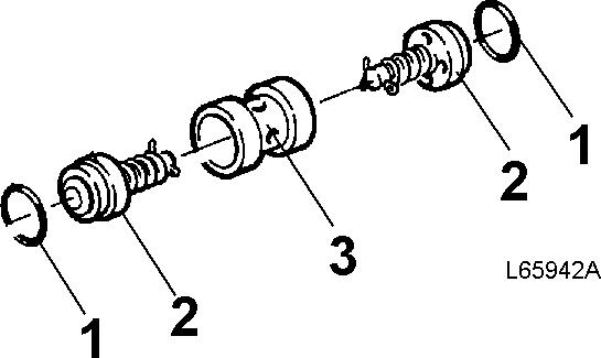
5 Shuttle valve 17 Spring 6 Plug 18 Piston 7 Gasket 19 Piston 8 O ring 20 Spring 9 Anti cavitationvalve 21 Shims 10 O ring 22 Housing 11 Control spool 23 Plug 12 Piston 24 Gasket T Tank connection 2. Remove the damping valves together with housing. Figure 2 1. Damping valve with housing 3. Dismantle the damping valves. Clean and check the parts as regards wear and damage. Replace the O rings and the springs. Assemble the damping valves. Figure 3 1. Housing 2. O ring 3. Shims 4. Spring 5. Piston 6. Spring 7. Non return valve 8. Piston 4. Remove the plugs and push out the shuttle valve. Clean and checkthe parts as regards wear and damage. Install
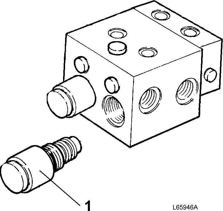
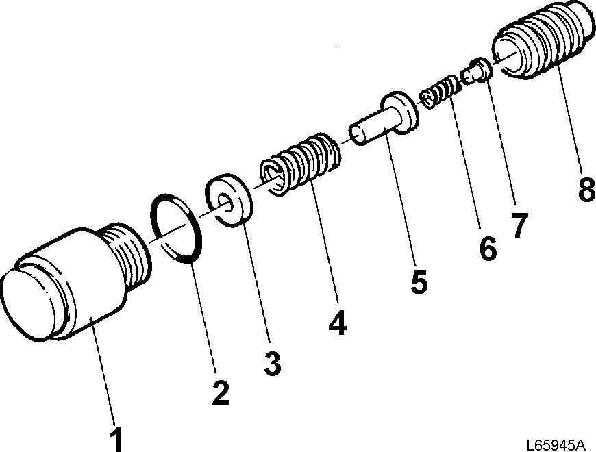
Figure 5 T Tank connection
7. Replace the anti cavitationvalves and the O rings. Install the new valves, the spacers and the newO rings.
5. Remove the six hexagon socket head bolts and remove the endplate.
Figure 6 1. O ring 2. Anti cavitationvalve 3. Spacer 8. Press out the control spools and the pistons from the housing (apply the pressure through the connections for the damping valves). Clean and check the parts as regards wear and damage. Replace the O rings. Install the spools, the pistons and the new O rings.
6. Use a bent screwdriver or a hexagon key in the tank connectionin order to press out the anti cavitation valves. Clean and checkthe parts as regards wear and damage.
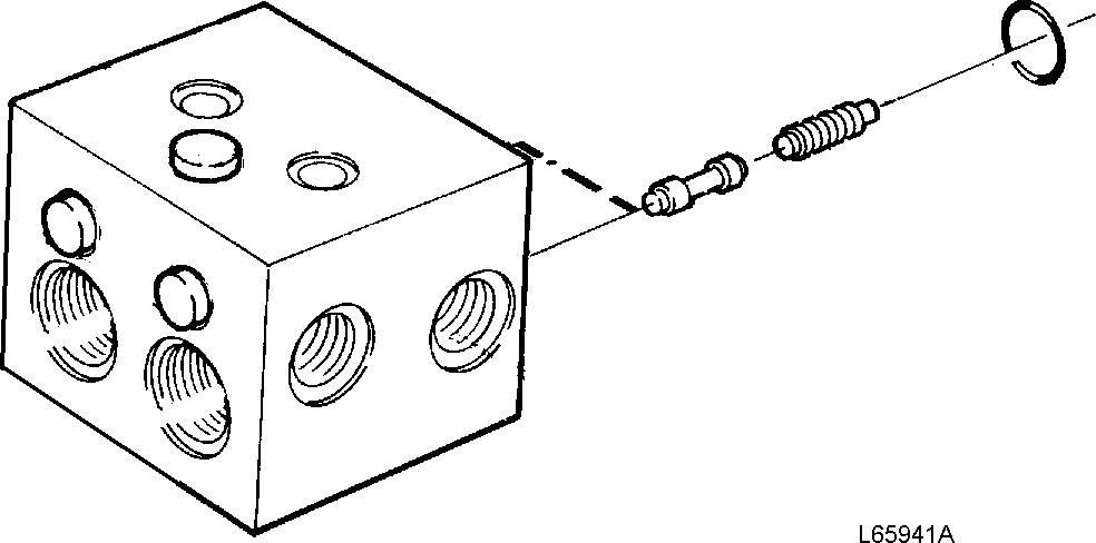
the shuttle valve,the washers and the plugs.
Figure Shuttle4valve
T Tank connection 9. Re install the damping valves together with housings.
Figure
Figure 8
7
12.
10. Remove the plugs and push out the non return valves (from the end plate side). Clean and checkthe parts as regards wear and damage. Replace the springs and install the non return valves, the new springs and theplugs.
11. Install the end plate and tighten it down with the six hexagon socket headbolts. Install the unions forthe tank connections.
Service Information Document Title: Specifications, general FunctionGroup: 645 Information Type: Service Information Date: 2014/5/27 Profile: Specifications, general Oil pump Type Axialpiston pump, variable displacement Designation PVE21LTA 2 30 CVP 12 214 882922 Flow at 35.0 r/s,(2100 rpm) and 10 MPa (100 bar) (1450 psi) pressure 91 litres (24 US gal) per minute Working pressure, high idling speed 21 ±0.35 MPa (210 ±3.5 bar)(3046 ±51 psi) Stand by pressure, low idling speed 3.0 ±0.3 MPa (30 ±3 bar) (435 ±44 psi) Steering valve Type Closed centre Designation OSPL 630 LS Valve block Designation OVPL 28 Shock valves Number of valves Two Opening pressure at 10 dm3(litres) (2.6 US gal) per minute 28 MPa (280 bar) (4061 psi) Steering cylinder Type Double acting Piston rod diameter 50 mm (1.969 in) Inside diameter / stroke 80/476 mm(3.15/18.74in)
Service Information Document Title: Stand by pressure and working checkingpressure,andadjusting FunctionGroup: 645 Information Type: Service Information Date: 2014/5/27 Profile: Stand-by pressure and working pressure, checking and adjusting Op nbr 6451564528 11 666 019 Pressure gauge 0 6 MPa (0 870 psi) 11 666 020 Pressure gauge 0 25 MPa (0 3626 psi) 11 666 035 Hose The following applies when checking: Temperature: Normal operating temperature Stand by pressure (Op. No. 64515) CAUTION Under no circumstances must the steering wheel be touched while checkingthe stand by pressure. The slightest deviation from neutral position will cause the pressure to rise and this may lead to damage to the pressure gauge. 1. Lockthe frame joint lock. Figure 1 2. Connect pressure gauge 11 666 019 (0 6 MPa) (0 870 psi) tothe pressure outlet on the steering valve.

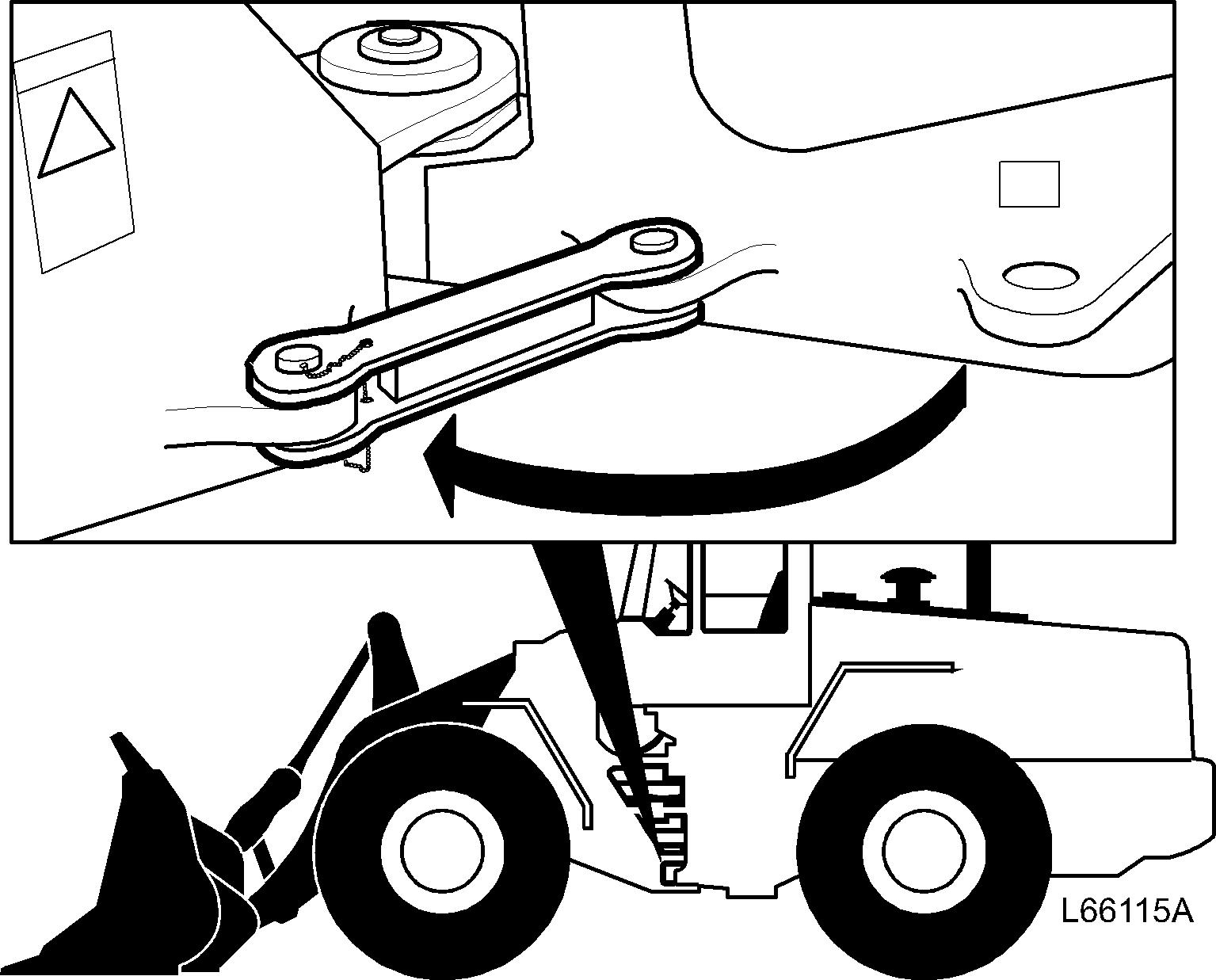

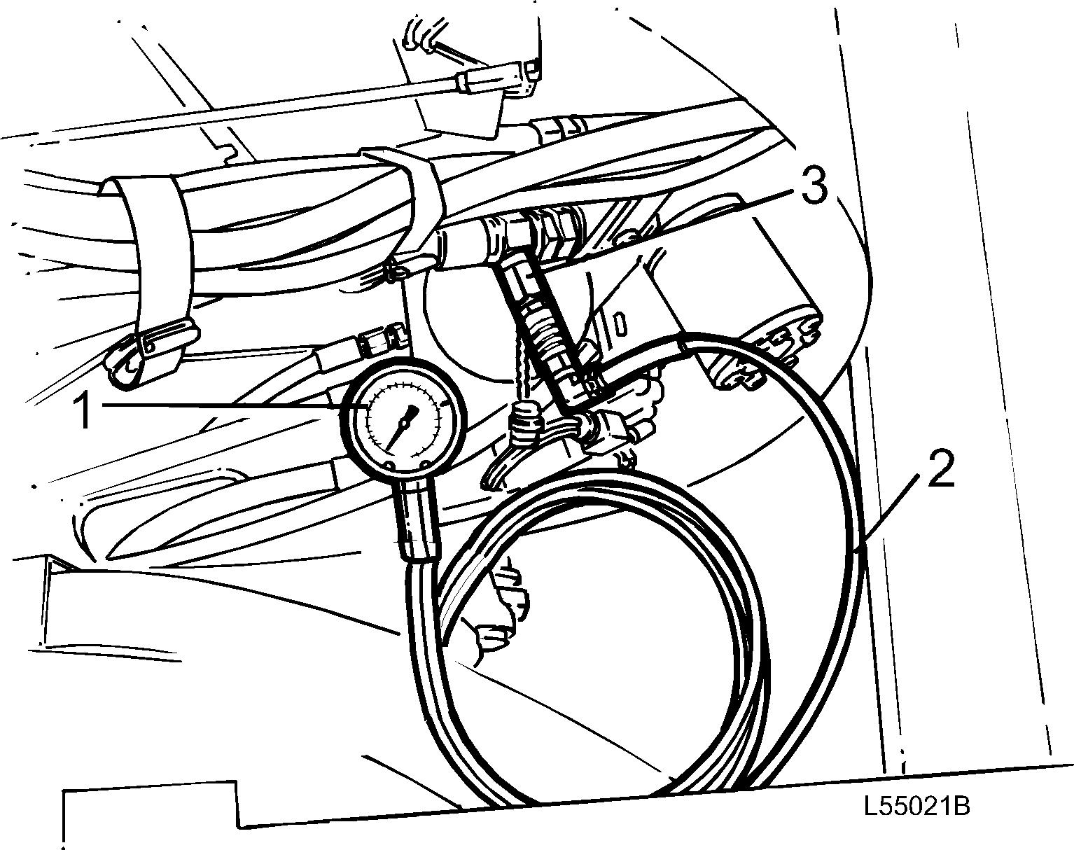
Figure Checking2 stand by pressure 1. 11 666 019 (0 6 MPa) (0 870 psi) 2. 11 666 035 3. Pressure outlet 3. Start the engine and run it at low idling.
6. Lockthe frame joint lock. Figure 4 7. Connect pressure gauge 11 666 020 (0 25 MPa)(0 3626 psi)tothe pressure outlet on the steering valve. Start the engine and run it at high idling.
4. Check the stand by pressure with the steering in neutral position (steering not actuated). Stand by pressure:3.0 ±0.3 MPa (435 ±44psi)
Figure Adjusting3 stand by pressure 1. Stand by pressure (lower adjustingposition) Working pressure (Op. No. 64528)
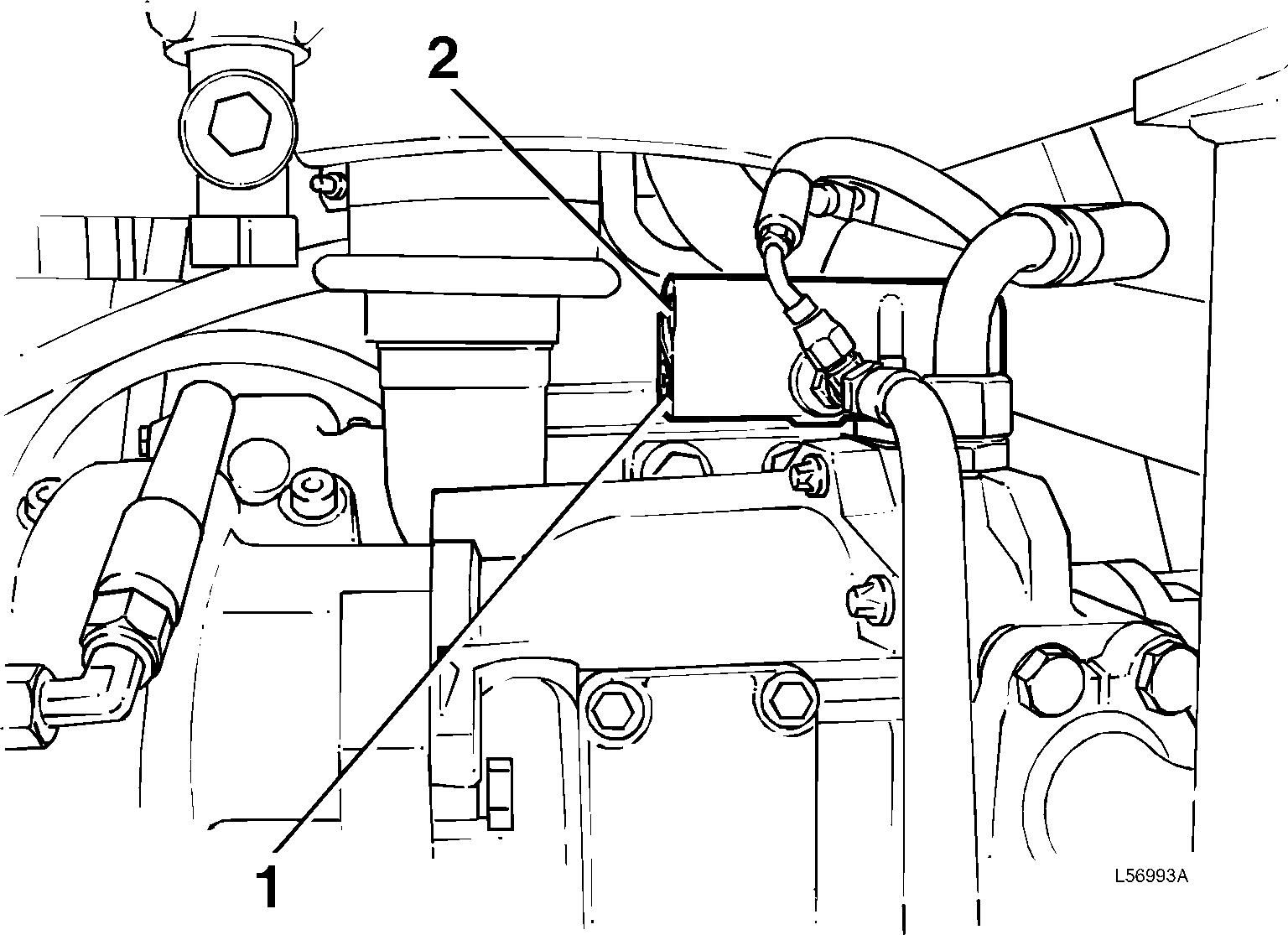
Adjusting 5. Any adjustment is carried out through the right cover behind the cab on the steering pump flow compensator. Remove the plug (hex socket 3/16") over the adjusting screw and adjust the pressure (hex socket 1/4"). Lock the plug with paint after adjusting.
Working pressure (upper adjusting position) Figure Checking5 working pressure 1. 11 666 020 (0 25 MPa)(0 3626 psi) 2. 11 666 035 3. Pressure outlet 8. Steer against full lockposition and checkthe working pressure. Working pressure: 21 ±0.35 MPa (3046 ±51 psi) Adjusting 9. Any adjustment is carried out with the screw on the steering pump pressure compensator. Lock the screw with paint after adjusting. Figure Adjusting6 working pressure 2
Thank you very much for reading. This is part of the demo page. GET SystemDescription,Instructions,System,HydraulicMORE:SettingFunctionalElectricalAndmore …… System And more…… Click Here BUY NOW Then Instant Download the Complete Manual.