66 minute read
From preventing warpage to replacing

Tech tips
From preventing warpage to replacing wheel studs
CHECKING HEAD FLATNESS
Whenever a cylinder head is removed, especially if overheating or head gasket failure has occurred, inspect the head deck for warpage.
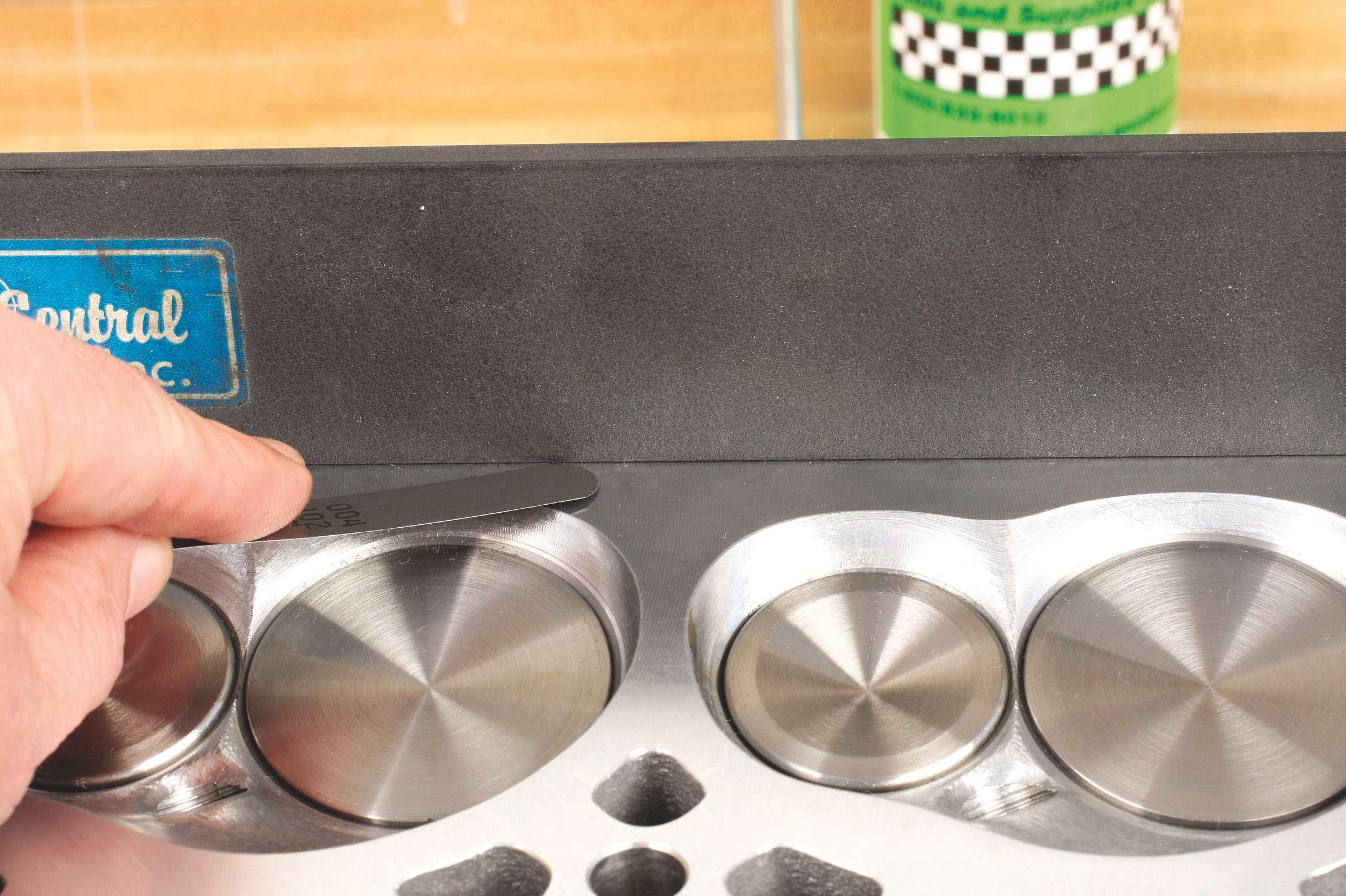
Clean the deck surface of any debris or gasket residue. Using only a precision machinist’s straightedge and a feeler gauge, measure for warpage from front to rear above the chambers, across the middle of the chambers and below the chambers. Also measure with the straightedge placed diagonally from the front top to rear bottom and front rear to rear bottom, as well as across the head from the intake side to the exhaust side, between each combustion chamber.
Always refer to factory limit specifications. A rule of thumb for aluminum heads for maximum allowable warpage is about 0.002 – 0.003 inch along lengths and diagonally, and about 0.002 inch from intake to exhaust sides.
When measuring, the straightedge must be firmly held down to the deck. Avoid placing the feeler gauge across any oil or coolant holes, as this will provide a false reading.
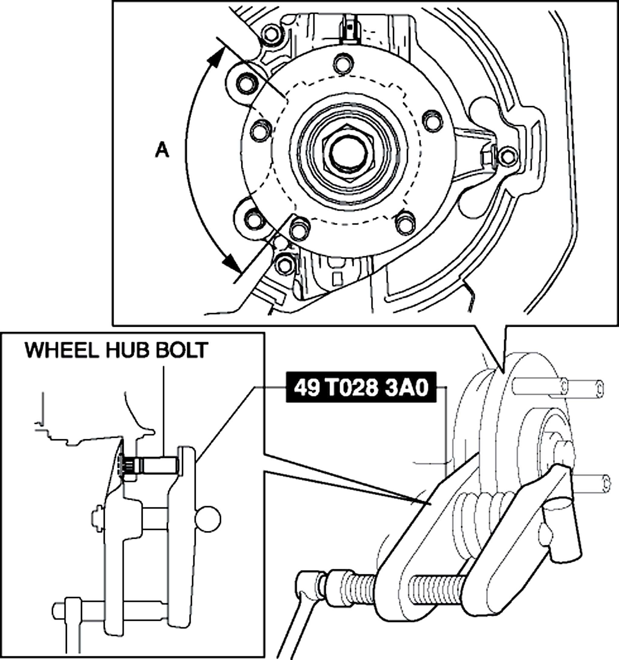
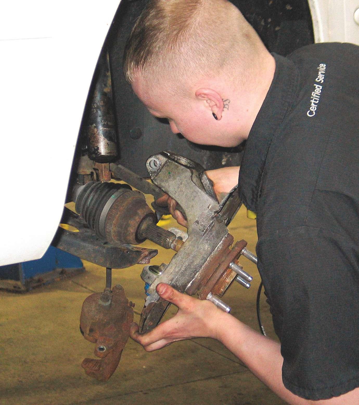
REPLACING WHEEL STUDS
As with anything, there’s a right way and a wrong way.
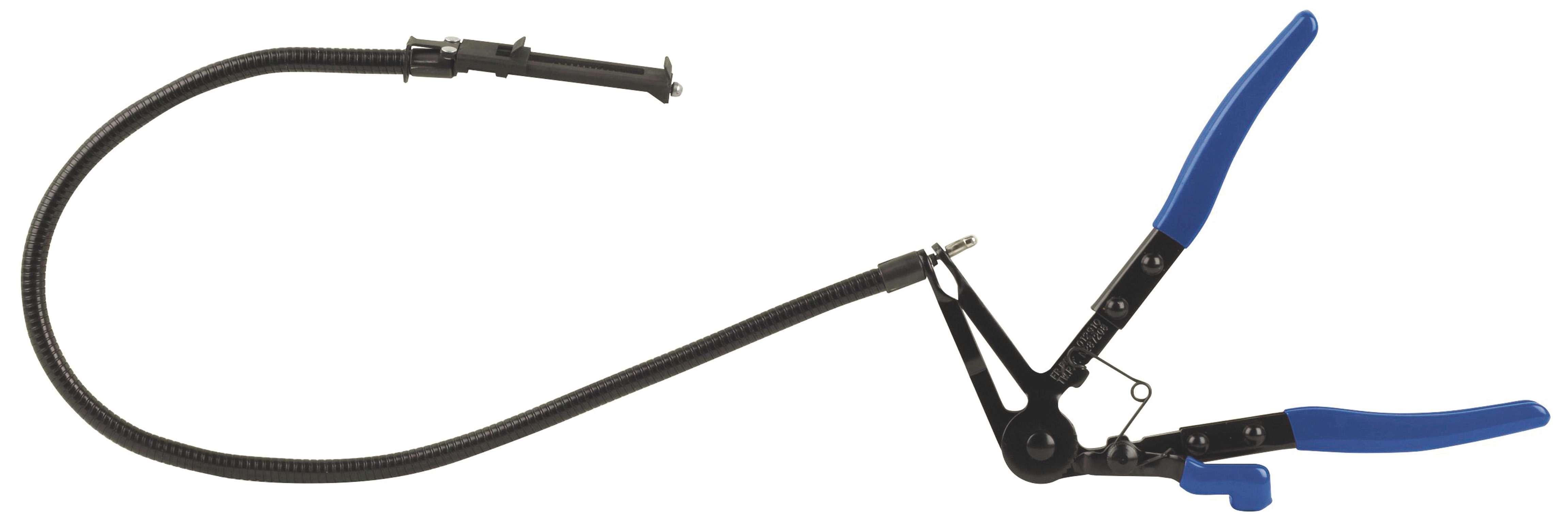
When replacing a wheel stud, use a manual press tool (Fig. A) to remove the old stud from the hub, as opposed to banging it out with a hammer, to avoid potenFig. A tial hub warpage. When installing the new stud, do not thread on a nut and try to pull the stud to engage the

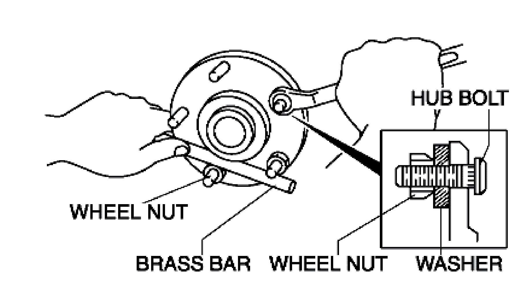
Fig. B
Measure for warpage from front to rear on each side of the combustion chambers and across the center of the chambers and below the chambers.

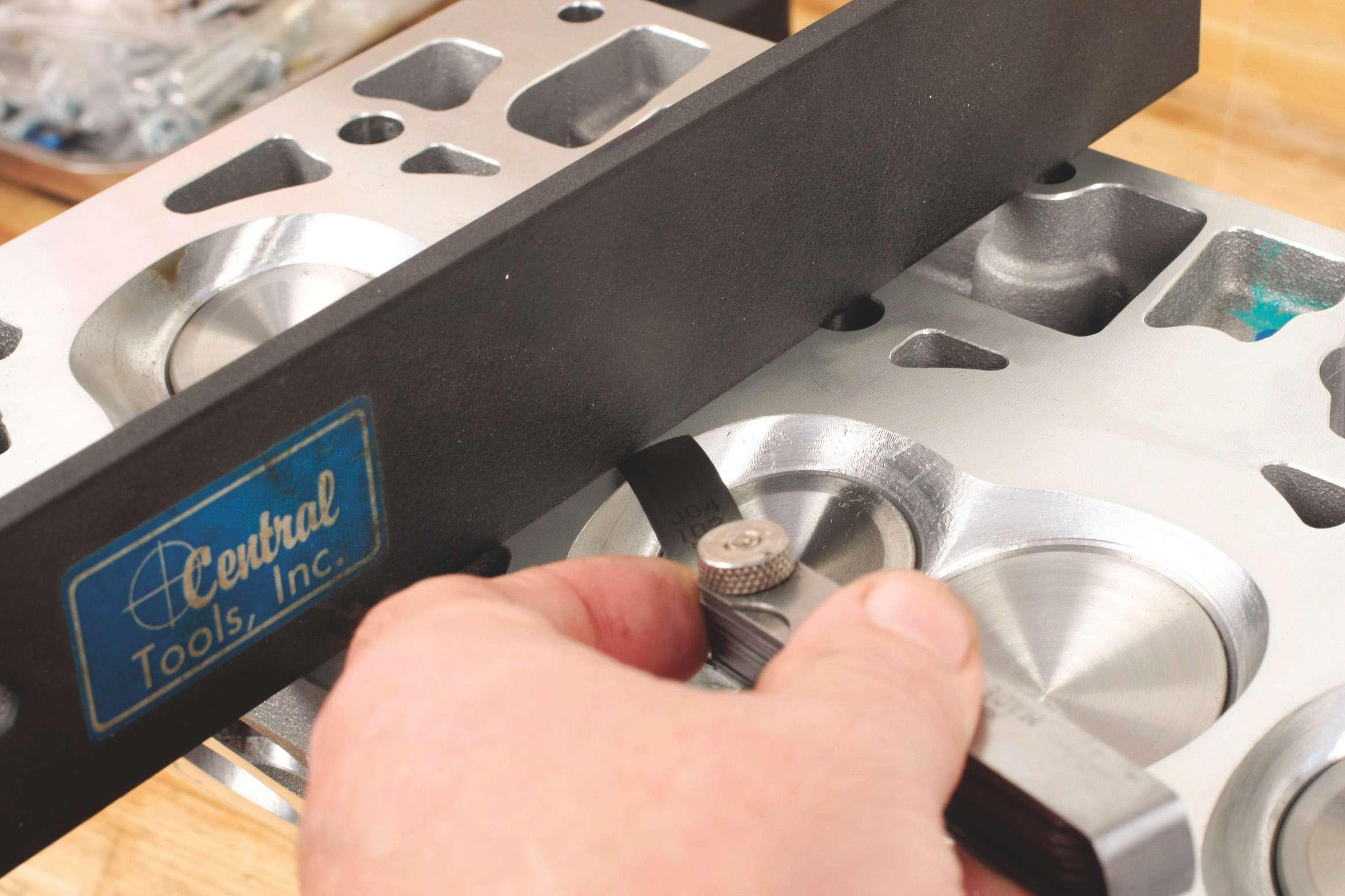
Measure the surface between the intake and exhaust side, between the chambers. splines using an impact wrench, as this can stress the stud and potentially damage the splines. Insert the stud from the backside of the hub, initially engaging the splines. Install a thick washer followed by a spare wheel nut of the proper thread size, and draw the stud fully using a hand wrench, while holding the hub stationary with a brass or aluminum bar across two of the other wheel studs (Fig. B). Tighten until the stud head is fully seated flush against its seat on the rear of the hub flange.

www.autoserviceprofessional.com 24/7 RESOURCE

ASP’s website is the go-to site for vehicle information 24/7.
Turn to it any time you need the latest technical service bulletins, indepth technical articles, the newest products and new tool reviews. Our site also features news from suppliers and manufacturers to keep you up-to-date on what’s happening in the automotive industry.
Plus, go to our website to renew your subscription to ASP, read the digital version of each issue and sign up for a free subscription to our weekly eNewsletter!
3515 Massillon Rd., Suite 350, Uniontown, OH 44685 (330) 899-2200, fax (330) 899-2209 Website: www.autoserviceprofessional.com
Publisher: Greg Smith / Greg.Smith@bobit.com
Editor: Mike Mavrigian / Mike.Mavrigian@bobit.com Managing Editor: Lori L. Mavrigian / Lori.Mavrigian@bobit.com Senior Editor: Joy Kopcha / Joy.Kopcha@bobit.com Associate Editor: Ann Neal / Ann.Neal@bobit.com
Contributors: Bob Weber/Automotive Technical Writer Jeff Taylor/Diagnostics & Driveability Specialist Bob Rodriguez/Hybrid & Alternative Fuel Specialist Jacques Gordon/Technical Contributor Advisory Board: Dan Paddy/Dan Paddy Service, Seville, OH Frank Dannemiller/Mobile Service & Repair Co., Wadsworth, OH Bob Fall/Fall Automotive Machine, Toledo, OH Scott Gressman/Gressman Powersports, Fremont, OH Greg McConiga/O’Daniel Automotive Restorations, Ft. Wayne, IN
Art Director: Neal Weingart / Neal.Weingart@bobit.com Production Manager: Karen Runion / Karen.Runion@bobit.com
Sales: Dan Thornton / djtinc@gmail.com (734) 676-9135, mobile (313) 410-0945 Michele Vargo / Michele.Vargo@bobit.com (330) 899-2200, fax (330) 899-2209 Marianne Dyal / Marianne.Dyal@bobit.com (760) 451-9216
Customer Service/Subscription Service phone: (888) 239-2455 / fax; (888) 274-4580 email: bobitpubs@halldata.com
Auto Service Professional is a Bobit Publication Executive offices: 3520 Challenger St. Torrance, CA 90503 Chairman (1961-2014): Edward J. Bobit CEO & President: Ty F. Bobit Chief Financial Officer: Armand Del Duca VP & COO: Cyndy Drummey
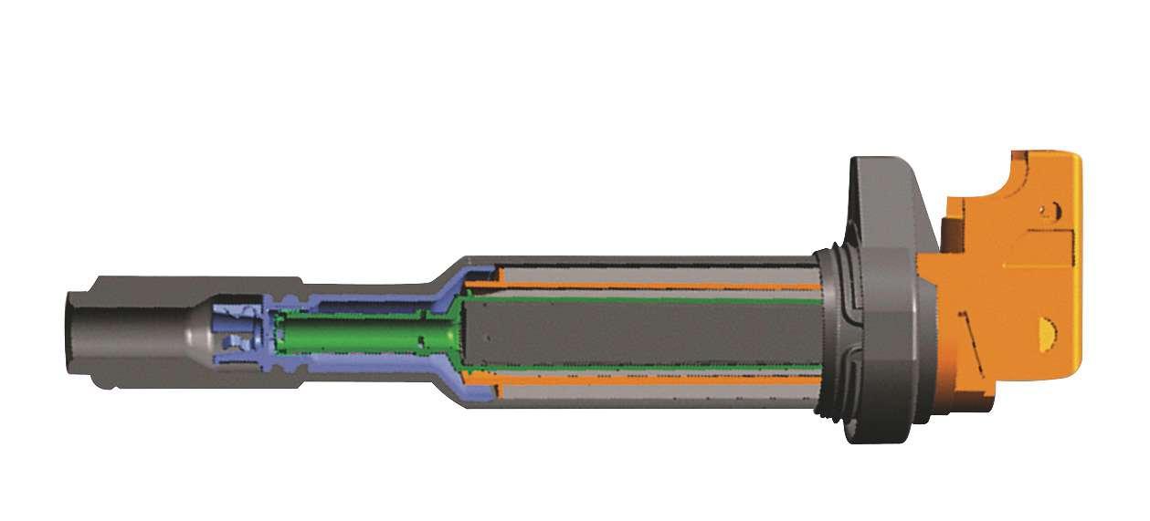
Coil-on-plug ignition
The art of COP misfire diagnosis
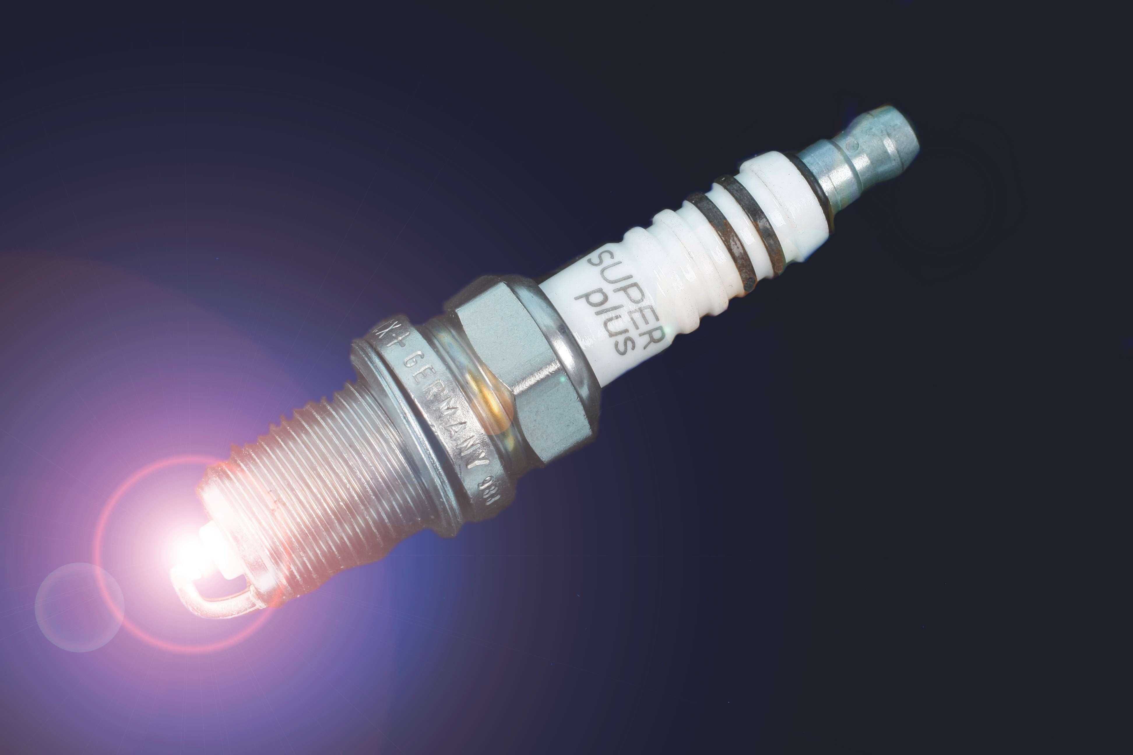
When an engine with coil-on-plug (COP) ignition starts to misfire, there are two challenges: finding out which cylinder is misfiring and finding out why. Even if you find a bad coil, simply replacing it is not the whole repair, because like so many other parts of a vehicle, COP ignition coils don’t really die, they’re murdered. We’ll discuss how and why later; first let’s focus on finding the misfire.
By Jacques Gordon
Ignition misfire diagnosis can be relatively quick and simple if you have the right tools. Fortunately, there are a lot of different “right tools” available, so it all comes down to the tools you know how to use. Most techs are comfortable using a scan tool, and if the malfunction indicator light (MIL) is on, a scan tool might be enough. But if the diagnostic trouble code (DTC) indicates a random misfire (P0300), the only thing you’ve learned is that the powertrain control module (PCM) “thinks” there’s an ignition-related misfire but it doesn’t have enough information to pinpoint the cylinder.
Remember, the PCM detects misfire with the crankshaft sensor: the crankshaft decelerates as a piston comes up on the compression stroke, then accelerates again on the power stroke after the cylinder fires. If it doesn’t accelerate as expected (per a very complex calculation), the PCM interprets that as a misfire and looks at all the input signals and output devices trying to determine the cause.
Trouble codes with a number lower than P0299 indicate the PCM has found a problem with something in the fuel control or air metering system. The codes from P0300 to P0399 indicate a malfunction in the ignition system, and while these codes can be
Ignition module
Primary coil
Secondary coil
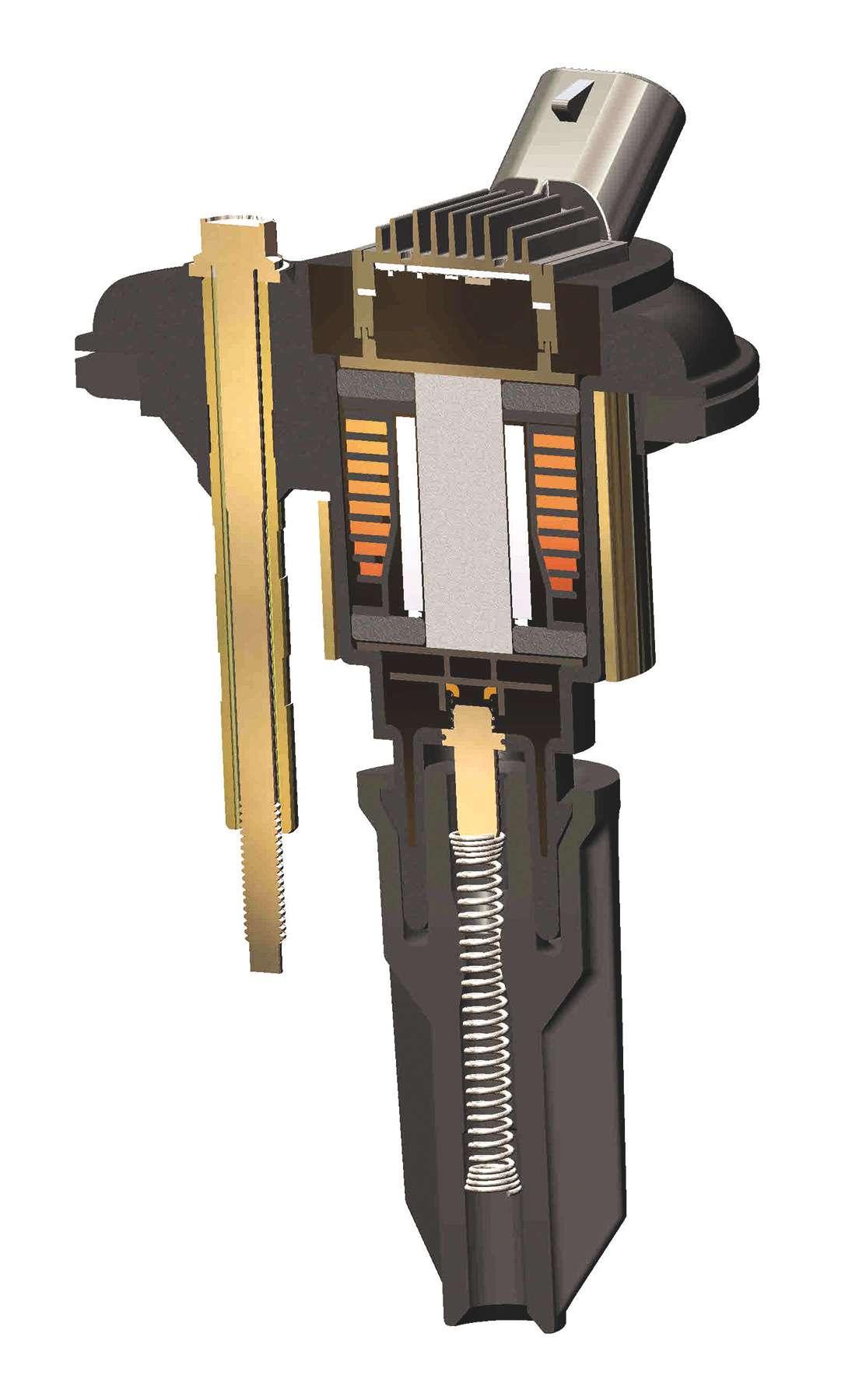
Magnetic circuit
Spark plug boot
Coil output
Large-wire primary winding surrounding the fine-wire secondary and a steel core in the middle. If the switching transistor (driver) is included, it may have cooling fins on top.
very specific, any code can be misleading. For instance, P0316 indicates the PCM has detected an ignition misfire within the first 1,000 engine revolutions after start-up. This code doesn’t tell you the real problem... it merely indicates the result of the malfunction. So even though it’s a P03XX code, does the PCM really know enough to be certain it’s an ignition malfunction?

Another design called a “pencil” coil has both windings arranged to fit inside the spark plug well.
We found a 2006 Dodge Dakota with a 3.7L V-6 engine that consistently misfires on cylinder No. 1, but only for a few seconds immediately after a cold-start. The PCM stored ignition misfire codes for cylinder No. 1, but a detailed and thorough diagnosis shows nothing wrong with any of the COP ignition coils. As it turned out, the misfire is a result of the conditions under which it occurs: only at cold-start and only on that cylinder, plus the position of the engine in the vehicle.
When the engine cools off overnight, the fuel in the rail cools and condenses, leaving a small pocket of vapor at the highest point in the rail, right next to injector No. 1.
Naturally the misfire clears up quickly as the rail fills with fuel, and there’s no reason to chase this problem any further (how could you possibly fix it?). But the question remains: Why did the PCM report this as an ignition misfire?
Component monitor
The answer is in the rules that regulate how OBD II works. According to those rules, all the sensors and output devices in the engine management system must be monitored to make sure they operate as expected. A section of software in the PCM called the comprehensive component monitor (CCM) checks most items only after specific conditions are met (coolant temperature, drive time, etc.), but some items are monitored continuously any time the engine is running. This includes fuel injectors and ignition coils.
The PCM monitors the fuel injectors by looking for open or short circuits. It monitors the ignition coils by monitoring the current in each primary circuit to see if it rises to the correct level and then falls again in response to the firing command.
In our misfiring Dodge, the injectors and ignition coils both pass the monitor tests, but the PCM has detected a misfire, and it must be recorded. Since the injectors pass the monitor test, the misfire is reported as a malfunction in the ignition system. This case may be unusual, but it shows why ignition misfire codes don’t always mean there’s something wrong with the ignition system or that there’s nothing wrong with the fuel system.
Here’s a little-known fact that can help you isolate the problem. You already know that when a cylinder misfires continuously, the PCM will turn off the dead cylinder’s injector to avoid sending gasoline straight into the catalytic converter.
However, it doesn’t remember the misfire, as it discovers the misfire anew each time the engine is started. So the PCM will operate the injector during cranking and for a short period right after start-up until it knows for sure the cylinder isn’t firing. If you’re watching the injectors on a ’scope and they all operate during the first 200 engine revolutions at start-up, the injectors are OK.
Let’s assume the scan tool displays a more useful code, like P0351 (Ignition Coil A Primary/Secondary Circuit Malfunction). This code is usually set because the ignition coil doesn’t pass the CCM. Remember, the CCM monitors the rise and fall of current in the primary circuit, and remember that power is supplied to all of the ignition coils through the same circuit. That means the CCM only needs to monitor one circuit to look for current rise/fall in each ignition coil. (By the way, ignition coil A is the first coil in the firing order, B is the second, etc.).
The monitor will see no change in primary current if the winding inside the coil is open or shorted. However, a broken power
or ground wire or a failed coil driver can all cause the same symptom and the same trouble code. Here’s where you need to know if the COP assembly has its own driver (transistor) that controls the ground side of the primary circuit. If there are just two wires connected to the coil, the driver is not in the COP assembly; it’s in a separate ignition control module or (most likely) inside the PCM.
If the coil has more than two wires, you’ll need a wiring diagram to determine how to test it. A coil with three wires has one for power, one for ground and one that carries the command signal from the PCM that operates the coil’s internal switching transistor. If there’s a fourth wire, that one sends a firing confirmation signal to the PCM.
Different tools
Many techs will test a coil primary winding with an ohmmeter, but that only checks the coil itself when it’s cold. If you back-probe the (two-wire) coil’s ground circuit at the PCM connector and look for battery voltage with the engine warmed up but not running (KOEO), that tells you something about the entire circuit. But even these tests have limited value: If the primary and secondary resistance are both correct and the whole circuit is complete, that still doesn’t prove the circuit works properly when the engine is running.
By now you get the point that a scan tool and a digital volt ohm meter (DVOM) don’t always provide enough information for an accurate misfire diagnosis. Any ignition system can be affected by heat and engine load, so testing a coil with the engine running gives you a more complete picture.
There is a new generation of easy-to-use tools that will show without a doubt whether or not the coil is firing. They’re based on magnetic induction, the same thing that makes a coil work in the first place.
By simply touching the inductive pick-up to the top of the coil, the tool picks up the rise and collapse of the magnetic field in the primary circuit. Some tools will simply flash a light to indicate the coil is operating, some display data on a small screen, and some connect directly to an oscilloscope to
There are several new tools with a probe that picks up ignition pulses just by touching it to the coil. Some just flash a light when the coil fires, some connect directly to a ‘scope, and this one has a screen to display secondary ignition voltage waveforms and primary current waveforms.

Circle 108 on
Reader Service Card
display a waveform of current flow in that coil’s primary circuit.
Of course the very best way to test any ignition system is with an oscilloscope that can display data from all the cylinders at once. You don’t even have to know that much about what actually appears in the waveform; if one doesn’t look like the others, you’re that much closer to finding the problem. The problem is, if you don’t use a ’scope regularly, you’re likely to

Fluke got out of the scope market a long time ago, and even though this one is slow by today’s standards, we still use it as the first step in locating a misfire. It take just minutes to find the ignition coil fuse, install a Fuse Buddy and connect an amp probe to look at the primary current on all cylinders. If they don’t all look the same, we’re already close to an accurate diagnosis.
forget how to set it up when you really need it.
Remember, the best tools are those you’re comfortable using. It only takes a few minutes to find the fuse that supplies power to all the coils and tap a ’scope into the circuit. Do it often enough to recognize known-good and you’ll quickly recognize something that doesn’t look right on any engine.
Before connecting an oscilloscope directly to the primary voltage circuit, check the ’scope’s maximum allowable input voltage. The primary circuit can create spikes of more than of 400 volts under normal conditions. Most voltmeters can handle this, but most oscilloscopes can’t and you’ll need to connect an attenuator to protect the ’scope. That’s one reason we prefer to look at primary current with an amp probe. An oscilloscope also lets you look at the control signal on three- and four-wire coils. This is typically a square wave signal of about 4 volts that matches the timing of the current ramp in the primary circuit. If you see the command signal but no current ramp, you know the PCM is good but the coil driver is not responding.
What killed the coil?
As noted earlier, even though COP coils are known to fail with some frequency, that failure is usually caused by something outside the coil. The most common causes are worn or incorrect spark plugs, excessively lean air/ fuel mixture and liquid getting into the spark plug tubes.
If primary current level and dwell time are correct, a coil will generate enough voltage to meet almost any demand. A healthy ignition coil with old worn out spark plugs might develop an initial firing voltage of 80 kV or more. That’s the coil doing its best to keep up with the demand, and for a while it will. But when a coil works that hard, the secondary winding
Why coil-on-plug?
The main reason for using multiple coils is to allow a longer and more controlled “on” (dwell) time to generate a stronger spark at any speed and load. It also extends the life of the coil because it gets more “off” (rest) time between firing events. This decreases the chance of a misfire at high rpm.
For example, at 3,000 rpm, an 8-cylinder engine will have 200 compression strokes per second. That means a spark plug fires every 5 milliseconds, which is just about the lower limit of dwell time needed to build a decent magnetic field with a reasonable amount of current (excessive primary current shortens coil life). As speed increases, dwell time in a single-coil ignition system decreases and the sparks get smaller and weaker, increasing the chance of a misfire. Spreading the work over multiple coils alleviates those problems.
overheats from generating that much voltage, and eventually the heat will damage the winding or the driver transistor. The coil will either begin to misfire when hot, or it will fail completely, or it will damage the driver.
To understand how hot a coil can get, look up Ford TSB 13-4-17 or 11-8-2. They include pictures of ignition coils that melted because the coil driver inside the PCM shorted to ground and kept the primary current turned on continuously (primary current normally lasts about 5 milliseconds). In case you’re not familiar with this (infamous) issue, the fix is to replace all the ignition coils and the PCM, which requires reprogramming the PCM, which in turn requires two original ignition keys to reprogram/reboot the anti-theft system.
Combine a worn out spark plug with lean air/fuel mixture, and that 80kV is going to find an easier path to ground. Even the best insulator boot can’t contain it indefinitely; at first the spark will leak through the boot to the valve cover only during acceleration, but


The boot on this Ford coil can be replaced separately. It did a reasonable job of keeping water out of the well that had splashed up from below during frequent off-road adventures.

eventually it will happen all the time. That’s why boots and connector springs are available separately on some models, so they can be replaced when installing new spark plugs. If the old spark plug has a carbon track on the ceramic, that boot should be replaced because there’s a matching track in the boot that offers an easy path to ground.
If there’s liquid in the spark plug well, even a new insulator boot might not be able to contain the secondary voltage. Chrysler issued a recall for the 2004-06 Dodge Durango (18-024-06) to replace ignition coils

This coil has a laminated steel core to enhance the magnetic field, but it’s exposed. It was replaced due to rust on the steel, which will gradually force the layers apart and possibly break the coil housing. New coils are fully coated. that were shorting through the (non replaceable) boot to the valve cover. The repair included installing a redesigned windshield cowl to keep rain water out of the engine compartment.
Other vehicles have had similar problems, but not just because of weather. Leaky spark plug tube seals, coolant leaks and even water or mud splashed up from below have all been known to cause this problem.
So now we’ve seen how the PCM detects and reports misfire, and we’ve shown that COP misfire diagnosis can be relatively quick and simple if you have the right tools. We’ve also discussed the importance of finding out what damaged the coil, because COP ignition really is simple and reliable as any other type of ignition system.
Jacques Gordon has worked in the automotive industry for 40 years as a service technician, lab technician, trainer and technical writer. He began his writing career writing service manuals at Chilton Book Co. He currently holds ASE Master Technician and L1 certifications and has participated in ASE test writing workshops.

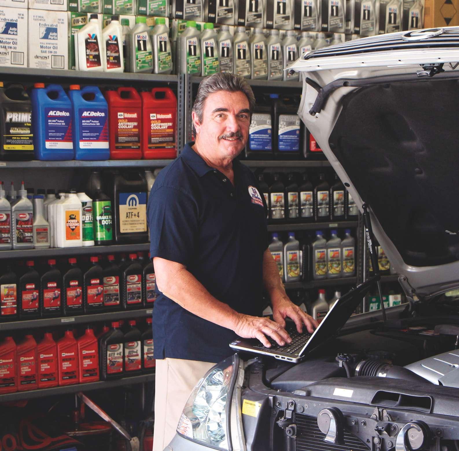
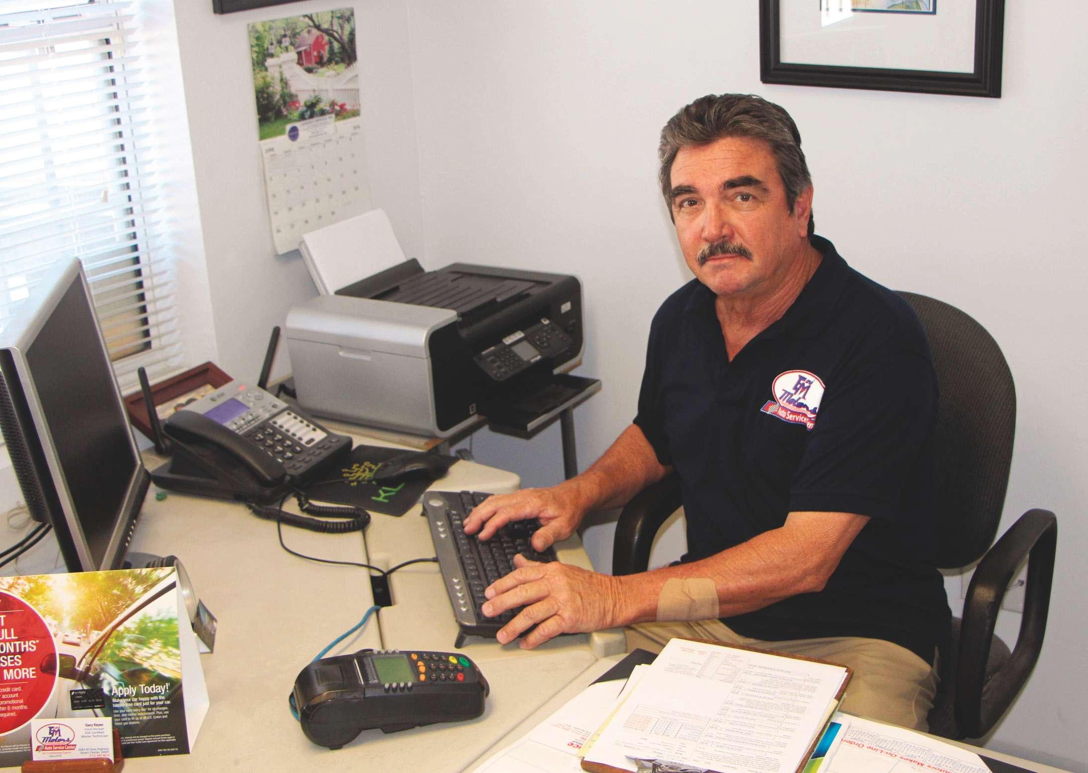
E&M Motors goes the extra mile
Shop earns loyalty through accuracy, timeliness and respect
E&M Motors is located in Stuart, Fla., about 40 minutes north of Palm Beach. The area is rich with history from Spanish galleon
E&M MOTORS Stuart, Florida Owner — Gary Keyes Business founded — 1974 (Keyes purchased the business in 1995 from a fellow ASA shop owner)
Number of bays — 6
Number of technicians — 2 ASE Master
Techs and one general service tech
Shop size — 3,000 square feet
Number of vehicles serviced per month — 125 (passenger cars and light trucks)
Hourly labor rate — Varies from $99 to $129 depending on diagnostics required
Average job ticket — $498
Gross profit — 60.7% Annual tool and equipment expenditures — $12,500 average, including technical service subscriptions Website — www.emmotors.net
shipwrecks to hurricanes and even a story about pirate Pedro Gilbert, who tried to board a U.S. Merchant ship in the 1830s, only to be caught and executed.
This Florida Treasure Coast community is also considered one of the best small towns in the U.S., as well as the Sailfish Capital of the World.
The county has a total population of around 175,000 people.
E&M Motors was voted “Best Auto
Repair and Service” for 2015 by the Stuart News readers for the 14th straight year. The community also named E&M Motors the best auto services and repair provider for 12 straight years.
Owner Gary Keyes says his shop offers general automotive repair as well as increasing specialization in Asianbranded vehicles.
The shop opened in 1974 and Keyes purchased it in 1995. Keyes has been servicing vehicles for 40 years and has been an ASE Master Certified Technician since 1978. He’s also an active member of the Auto Service Association (ASA), and a strong advocate for membership in that organization.
Keyes was kind enough to share his philosophy, business approach and some financial information with ASP.
Specialization
While the shop has traditionally serviced most makes and models, Keyes noted that the shop’s emphasis is now shifting somewhat in order to place greater focus on specific
Keyes’ parts purchases are made primarily based on quality and availability, with both warranties and brand name recognition running a close second. greater clarity and direction. the problem right the first time, in a timely manner and at a fair price,” said Keyes.
“We make a point to take the time to educate the customer with regard to the need for regular inspections and preventive maintenance, which can eliminate 90% of potential break-down issues.”
Parts purchasing
When asked about what factors he considers in his parts buying decisions, Keyes provided a ranking, from 0 to 3, with 0 having no influence and 3 having the greatest influence:
Price.......................................1
Brand name recognition .....2
Promotion in racing ............0
Quality ..................................3
Availability/time ..................3
Warranties............................2* *Some parts offer a lifetime warranty, which is always a consideration.
“In terms of quality,” he noted, “the number one consideration is actual quality, as opposed to perceived quality. We know, from experience, what brands we want to buy, which can, on occasion, differ from a customer’s notion of perceived quality. “We don’t want a comeback due to an inferior part, so we stress the use of what we consider quality
brands including Toyota, Lexus, Owner Gary Keyes emphasized the Acura and Honda. He noted shop’s ongoing goal of establishing a that “this makes tooling and high level of trust from customers from the outset. The shop has gained an exparts stocking easier, with tremely loyal customer base as a result. We stay away from high-end German vehicles and time... the speed though, which is a niche unto itself.” at which we can obtain The E&M shop boasts two the part is crucial. highly qualified ASE Master Business philosophy Price is way down on Techs and one general
“In order to gain loyal new customers, you the list. If we want OE need to establish a high level of trust from quality for a specific application and it costs the outset. We go the extra mile to assure a bit more, we’re OK with that. It’s all for the the customers that they’ve come to the right benefit of the customer and for our shop’s place by treating them with respect and fixing reputation for quality,” said Keyes.
parts. Availability service technician.
Keyes’ shop buys directly from a Federated WD. Interestingly, he buys OE parts through them, buying directly from new-car dealers “a couple of times each month.”
Keyes does buy from local jobbers, but since one jobber changed affiliation, he no longer buys from them.
Leak detection
Smoke, dye and electronic methods
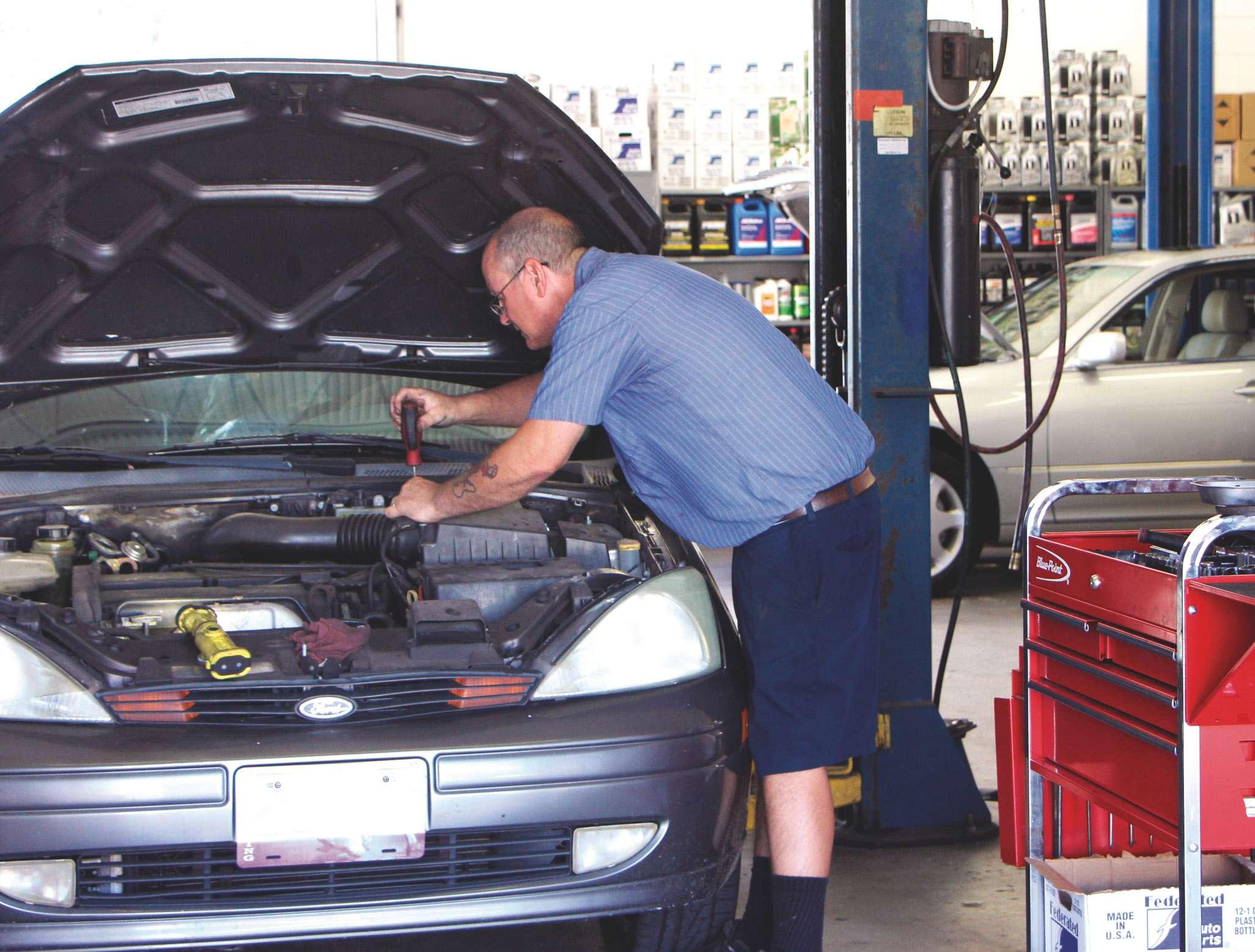
The average age of cars and light trucks on the road is now 11 ½ years, according to research from the latest Auto Care Association Factbook. Think about that for a moment. It means that you are dealing with higher mileage vehicles and the issues that result for long-term wear and tear. Specifically, it means that fluid, coolant, vacuum and A/C systems are going to start leaking, causing problems. Finding the leak and fixing it can be challenging unless you have the right equipment and knowledge for the task. Let’s examine what you need to do this work.
By Jeff Taylor
Leaks come in many forms. Fluid leakout can include coolant, lubricants, exhaust or refrigerants, but leak-ins can also occur, such as unmetered air in an intake system. The results can bring about different customer complaints, from overheating, dash lights, to being uncomfortable on a hot day, but the result is that at some point a technician is going to have to identify the leak and make a repair.
If it is a very obvious leak, for instance a blown upper radiator hose, a careful visual inspection is likely the only diagnostic needed to identify the concern followed by a straightforward repair. But that isn’t always the case anymore, and with the architecture of many newer engines requiring extensive disassembly to repair, making sure that you have properly identified the leak has never been more imperative.
Using a fluorescent dye for leak detection
Vehicles generally have a number of fluids involved in their proper function (coolant, engine oil, transmission fluid, refrigerant, etc.), and other than washer fluid and fuel (dyes are available for fuel leak detection) these fluids are contained in their own systems and not meant to be consumed or leak out.
As the engine ages, gaskets and seals degrade from the mechanical forces, movement, vibration, heat, corrosion and a number of other factors. Seals and gaskets are going to get hard and less flexible. Corrosion and wear are going to happen and this is eventually going to result in a leak.
The majority of engine leaks were easier to pinpoint in the past, and identifying the actual source of the leak was commonly straightforward. Yes, there were challenges, but since access was relatively generous, engines weren’t that complex, nor were they mounted sideways or covered in noise quieting plastic shields. But that isn’t the case anymore, as the under hood area is now crammed full and space is at a premium. Some form of disassembly is now going to be required to properly diagnose most leaks under the hood and pinpointing the actual source of the leak can be a complicated task.
Water pumps, for instance, are frequently mounted internally on today’s engines, with a


weep hole in the timing cover. But this weep hole is usually hidden under an accessory, making it very difficult to identify the actual source of the leak. Is it the timing cover? Is it the head gasket? These leaks are not just frustrating, they are time consuming to properly diagnose, necessitating a method of leak detection that provides accurate results in a timely fashion, the first time.
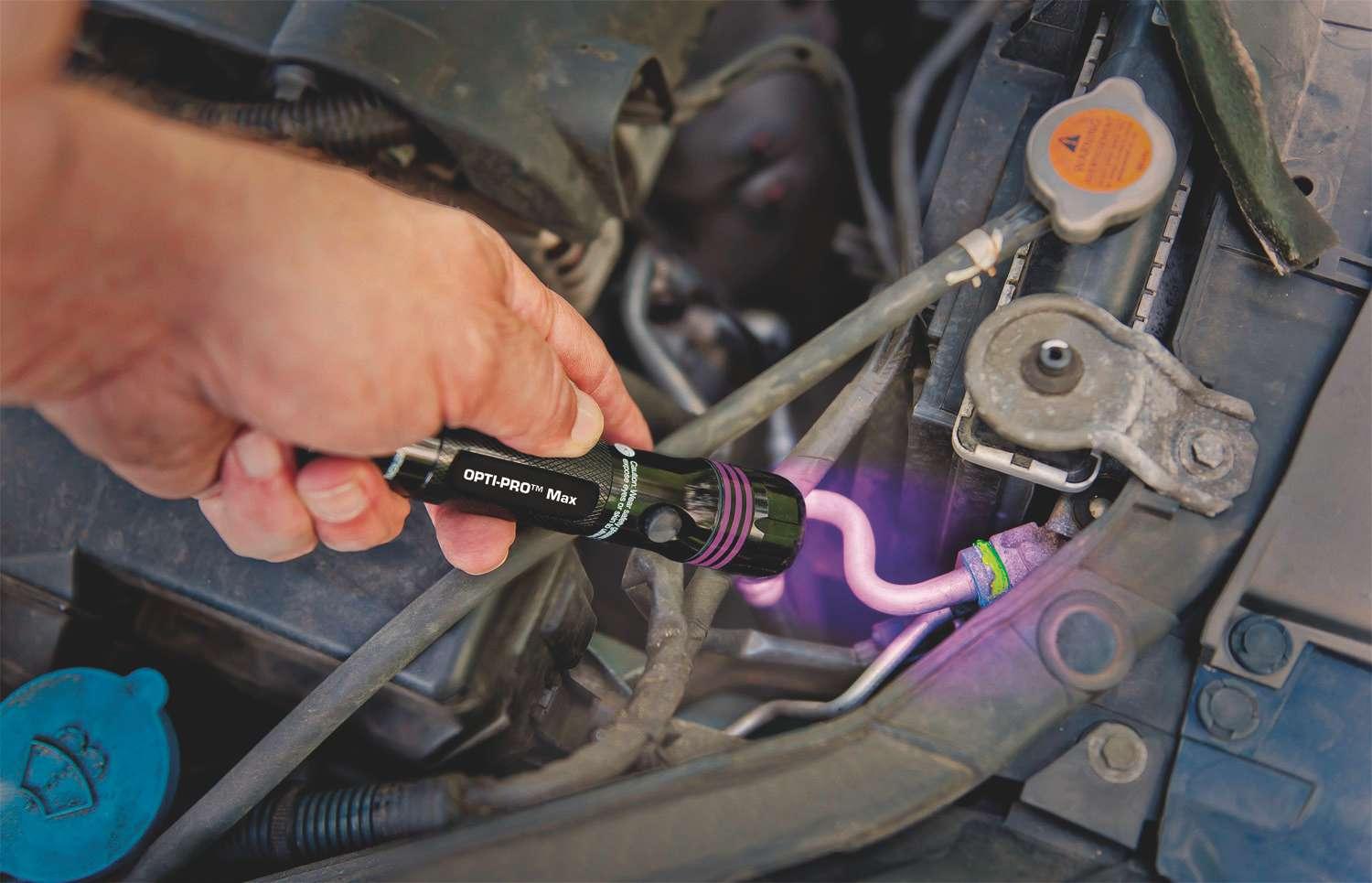
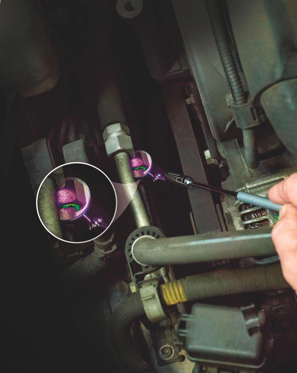
One of the best ways to diagnose a fluid leak quickly and accurately is by adding a fluorescent dye into the leaking system.
The use of a fluorescent dye in Compact and efficient hand-held UV and blue lights are availcombination with an ultraviolet able with rechargeable batteries, in varying sizes and light (UV) or blue light inspection combinations (UV only, blue only and UV and blue). lamp is not new. The technology has been around for some time, but the dyes, appropriate detection light to expose the leak and the lights used to identify the leak, have that will need to be repaired. improved immensely. Today’s detection lights are now offered in
There are now dyes that can be added to a vast number of handheld styles. Most use nearly all the fluids that could possible leak LEDs that are longer lasting, cooler operating, from a vehicle, even the air brake systems of rechargeable and much safer than previous heavy-duty trucks. Once the dye is added to incandescent versions. They produce the the system, it has to be circulated with the UV or blue light required to make the dye fluid that is leaking. glow brightly and come in a myriad of styles,
And after circulation the leaking system shapes and designs. There are even lights has to be thoroughly inspected with the available that are double ended and create both UV and blue light in one application. The most vital part of using a leak detecting dye is using the correct light to detect it. This can’t be stressed enough. The use of poor quality dyes and improper UV or blue lights just won’t give the most accurate results and can lead to frustration for the technician. Using a UV light to find a leak on an AC system that has blue light dye installed might not show the leak’s origin. Worse, the entire area being examined may glow and that’s not going to help identify the issue. Having both a UV and a blue light is your best bet in fluid leak detection, but attention to the dye’s instructions is imperative. UV detection lights are also offered in a wide variThere are now many dyes that are full-specety. For pinpointing tight-access areas, a thin teletrum and compatible in many fluids (lowering scoping light with a built-in mirror aids in finding cost and inventory) and glow when exposed to leaks in areas not readily accessible by eye. either style of detection light.

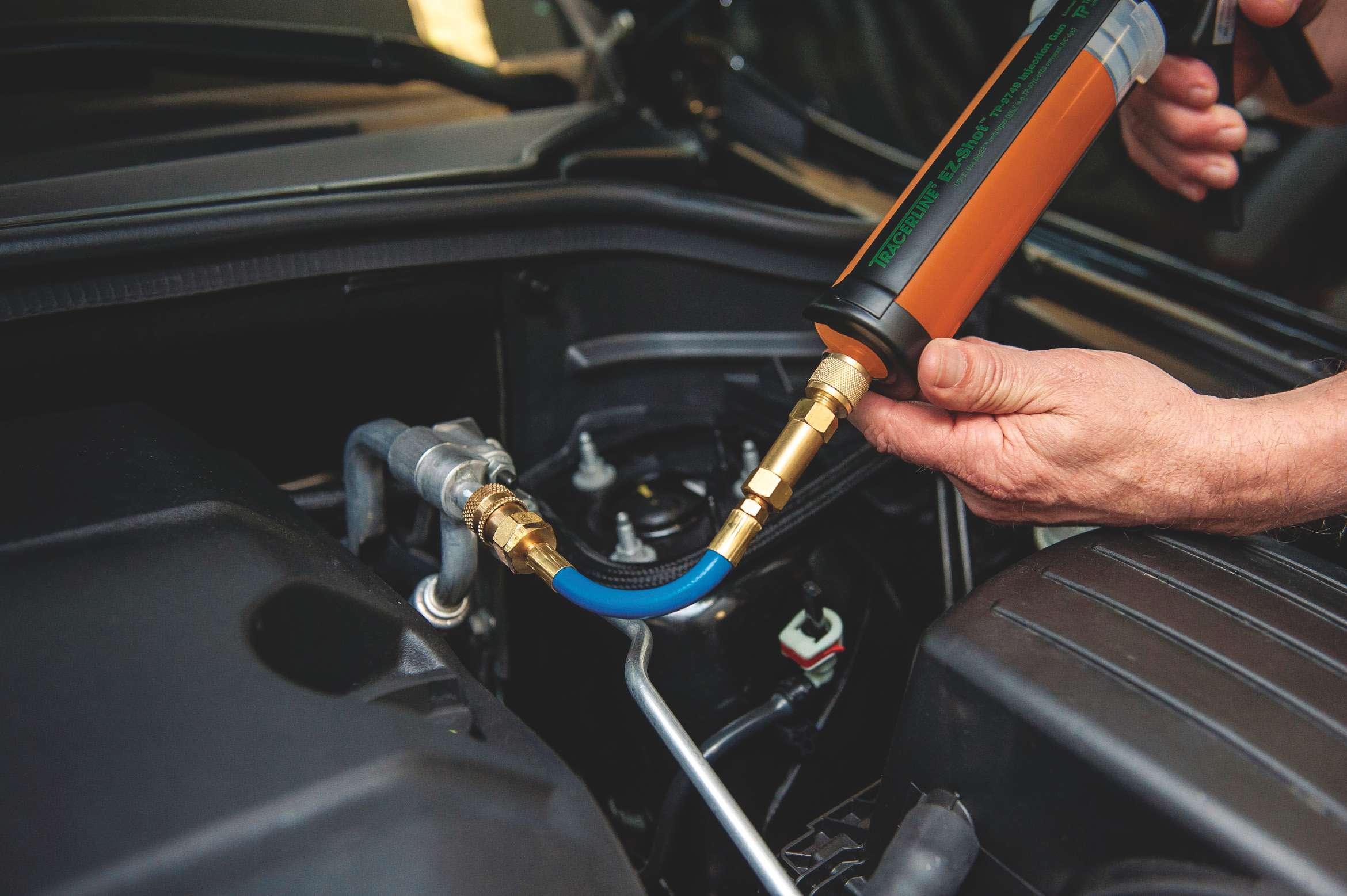
Similar to a grease gun, this injector adds dye with hand pressure. A variety of dye delivery tools are available for A/C dye injection. Shown here is Tracerline’s TP-9791 EZ-Shot for R-1234yf.
In addition, many manufactures are factory-installing dye in several of their fluids, cutting down on diagnostic time if there is a warranty issue. Careful inspection with your leak detection lights may reveal the area of concern before you add a dye into a system as you look for the source of the leak.
AC system dye has been a very popular leak detection method for years, and again most manufactures factory install dye in their AC systems. Carefully inspect first with your detection light/lights, even if the system is empty. If the system had dye in it before it lost its refrigerant, the florescent glow should remain at the source of the leak.
But if the system wasn’t factory dyed, a dye will have to be added. The AC dye is mixed into refrigerant oil to allow its installation in the vehicle’s AC system. The correct dye must be used: The oil that it is contained in has to be compatible with the AC system that you are dealing with. There are universal, dedicated PAG, Ester and R-1345yf/PAG oil dyes now available. Today’s AC systems hold very little refrigerant and refrigerant oil. They are very sensitive to an oil overcharge, so great care must be taken not to overfill the system.
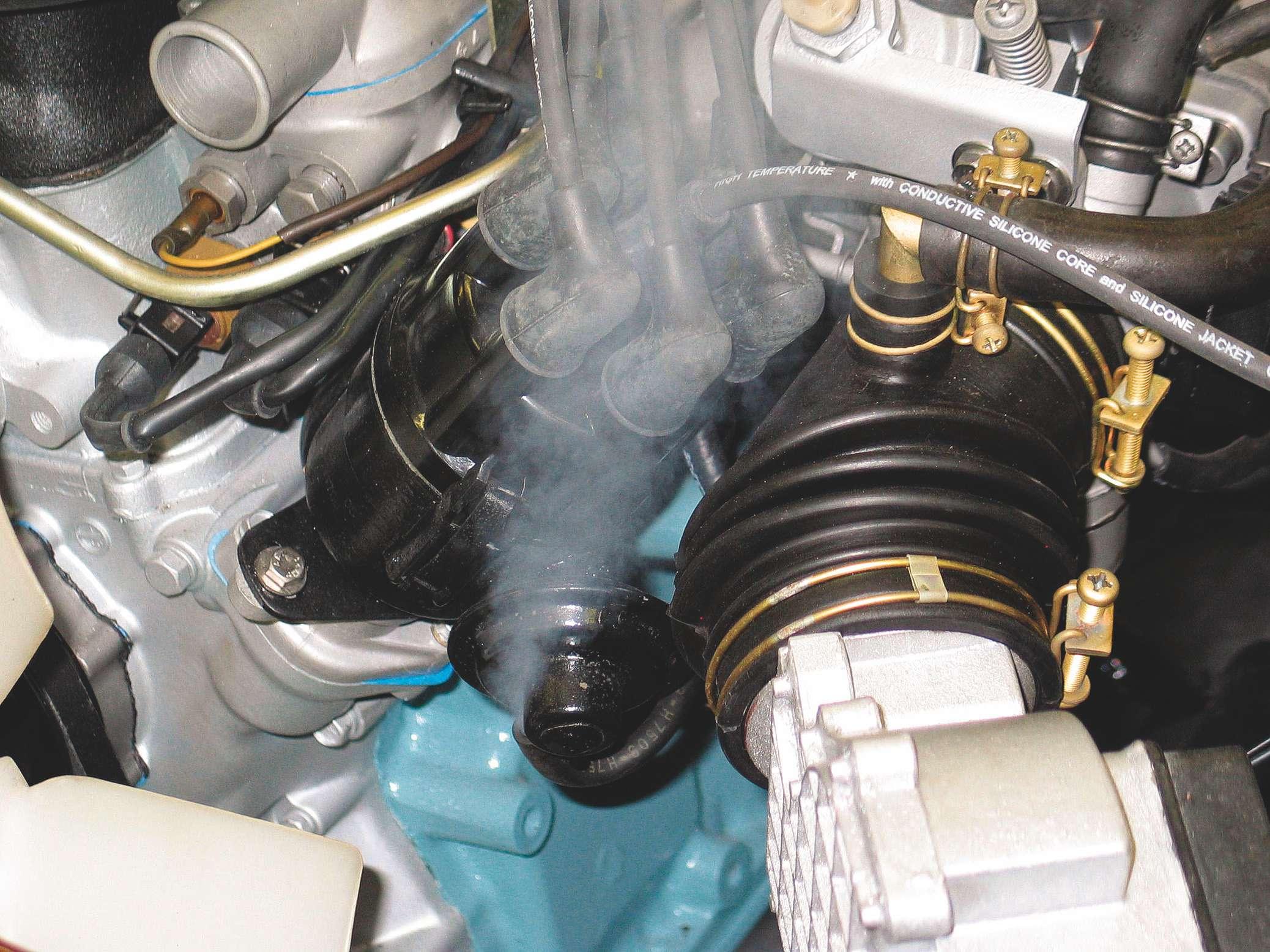
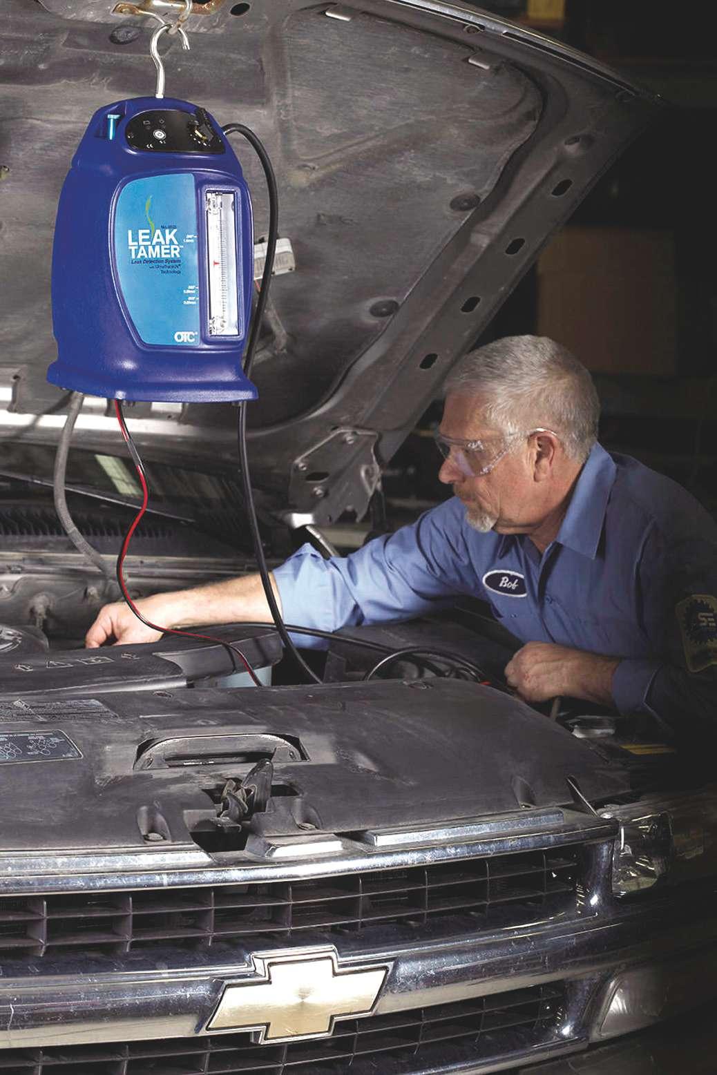
Using a smoke machine
When dealing with a system that doesn’t have a fluid to transport a dye for leak detection, the smoke machine is an essential tool. Smoking out the leak in an evaporative system has been a mainstay for many years, and most of us have developed our own techniques. The EVAP smoke machine developed a low pressure, required to properly diagnose the EVAP system without doing any damage. This was mandated by the manufactures to allow testing, and many machines didn’t allow you to increase the testing pressure, all in the name of safety and the fact that the systems operated at such a low pressure during actual operation.
The same follows for intake leaks, and unmetered air entering the engine that can cause a variety of different engine codes. The naturally aspirated engine intake system operates under a vacuum or close to atmospheric pressure, but with the surge in turbo equipped engines, a different type of smoke machine is required.
The high pressure smoke machine is not designed to be used for EVAP diagnostics; it was designed to produce a pressure up to 20 psi, and be used to detect leaks and issues in the high pressure intake and exhaust systems of today’s popular forced induction engines.
The traditional low pressure smoke machine is not capable of simulating pressures in the intercoolers, turbos and ducting that may only leak when under a boost situation. If
Circle 112 on Reader Service Card


created by leaks in the pressurized side of the intake system that will not show up in the service bay at idle because there is little turbo boost pressure.
But the intake side of the engine is not the only area that a high pressure smoke machine can be used. The exhaust side is susceptible to leaks as well and many of them go unnoticed. But an exhaust leak can cause a number of issues that are often misdiagnosed.
Catalytic codes P0420/P0430 are in the top 10 of OBD II codes generated is installed, only to have the code return. When the powertrain control module (PCM) decides to perform a catalytic efficiency test, it is assuming that the exhaust system is sealed front to back, and calculates its decisions on this fact. But if there are any leaks, even small pin holes, the false air introduced will skew the readings of both air fuel and downstream O2 sensors and directly affect the PCM’s test results.
These leaks are often insignificant and don’t even create enough noise to alert the customer, but that doesn’t mean the PCM doesn’t see them. Pressurizing the exhaust system with a high pressure smoke machine will quickly tell you if you have any false air entering the exhaust system close to any of the air/fuel sensors or downstream O2 sensors. It will detect cracks, gasket leaks, broken bolt locations and weld failures that can allow fresh air to be sucked into the exhaust system and possibly cause a false converter code, when there is in fact nothing at all wrong with the convertor.
The high pressure smoke machine can also be used to diagnose cooling systems and wind and water leaks, something that a low pressure smoke machine just isn’t capable of doing.
Smoke machines are invaluable for chasing a multitude of external leaks, especially vacuum, EVAP, fuel cap and exhaust issues. Electronic leak detection these systems leak, poor performance, noises, egories; electronic refrigerant testers and and engine trouble codes can be generated. ultrasonic testers. The electronic refrigerant
Boost codes and fuel trim codes can be tester has been forced to evolve over the
Electronic leak testers fall into two catyear after year by today’s fleet, and Depending on the location, escaping smoke is visible many times a new catalytic convertor under available light or with the use of a UV light.
Circle 11 3 on

Reader Service Card

Ultrasonic leak detectors use sound waves to detect leaks that convert and amplify ultrasonic noise into audible noise, via technician headphones. Applications include air brake leaks, compressed air leaks, vacuum leaks, gear and bearing wear, exhaust leaks, gasket integrity and more. Tracerline’s TP9367 Marksman II is shown here checking an air brake system. Ultrasonic leak detectors offer a wide range of testing including leaking door weatherstrip seals, electrical discharge and more. years to keep up with the types of refrigerant available. The introduction to R-1234yf is yet another part of the evolution that is going to take place.
Many of us already have an electronic leak detector of some description that we are using to check R-134a systems, but this detector may not work on the newer R-12134yf. Remember that R-1234yf is slightly flammable, so the proper detector is a must.
There are a number of new SAE performance standards for electronic refrigerant leak detectors and they are available at the SAE or MACS websites to make sure that your test equipment meets the current standards.
Many newer electronic testers now incorporate a dye detection UV/blue light on the sensor tip to aid in pinpointing the leak. The electronic refrigerant detector does have issues that the user needs to be aware of: The A/C system that you are leak testing must be charged with refrigerant for it to work, the detector has to be calibrated and properly serviced and they don’t like air movement over the sensor tip. The detection tips have a life span and wear out, filters have to be changed and most don’t like to have any air movement near the sensor head at all or false results will be indicated (for instance, don’t hold them in the vent duct with the fan on).
Following the operating manual and service procedures are paramount for accurate results.
Ultrasonic testers on the other hand are not susceptible to air movement and don’t require the system to have refrigerant in them to work, as the A/C system can be pressurized with an inert gas. The ultrasonic tester detects to the inaudible ultrasonic sounds that a leak creates, even in a loud noisy environment, but this tester isn’t limited only to A/C systems. It can also be used to find intake leaks, air leaks, exhaust leaks and vacuum leaks.
Choosing the leak detection method
Finding a leak is going to require an action plan, and that plan is going to depend on what type of leak you are dealing with.
Florescent dye fluid leak detection is accurate, easy and eliminates much of the guess-work in leak detection, making our job as techs more efficient, but the correct amount of dye has to be installed and the


Here’s an alternative to dye or smoke. An electronic refrigerant leak detector “sniffs” R-12, R134a or R-1234yf. According to the manufacturer Tracerline, the TP-9360 PRO-Alert is capable of detecting leaks as small as 0.25 oz./year. correct light has to be used for the ultimate results. The system being diagnosed will dictate the form of leak detection method you are going to use.
If you have a power steering fluid leak or a fuel smell, for example, the use a dye compound and detector light to find the issue is the best bet. If you have an A/C leak you are likely going to use a combination of methods (dye and electronic) making your diagnostics more precise. A P0420 is going to lead me to install a high pressure smoke machine to the tail pipe to check that there are no exhaust leaks that could cause a false code.
NOTE: The link below is to the SAE/MAC website and lists all the SAE requirements for A/C tools and equipment: http://www.sae.org/macdb/gethome.do.
Jeff Taylor boasts a 31-year career in the automotive industry with Eccles Auto Service in Dundas, Ontario, as a fully licensed professional lead technician. While continuing to be “on the bench” every day, Jeff is also heavily involved in government focus groups, serves as an accomplished technical writer and has competed in international diagnostic competitions as well as providing his expertise as an automotive technical instructor for a major aftermarket parts retailer.
Strut service tips
Servicing suspension struts requires attention to detail
When a customer comes in and says the car is not riding “right” or there’s a clunking sound from underneath, it’s important to do a thorough investigation before jumping to any conclusions. When the vehicle has a strut suspension, you need to understand how all the components work together and which ones are most prone to wear. Here are strut service tips that should be used whenever working on vehicles.

By Mike Mavrigian
In this article, we’ll discuss basic strut removal, service and installation. Let’s dive right into it.
With the vehicle raised, and before removing the wheel assembly, place a matchmark on the wheel stud that is closest to the air valve stem. This will provide a reference to reinstall the wheel in the same position. Just in case there is a stack-up of tolerances between the wheel and hub, this avoids the potential of creating a lateral runout condition and resulting vibration that could cause a comeback.
Once the wheel is removed, detach any items that are currently secured to the strut body such as an ABS wire harness, anti-sway bar end link and/or brake hose.
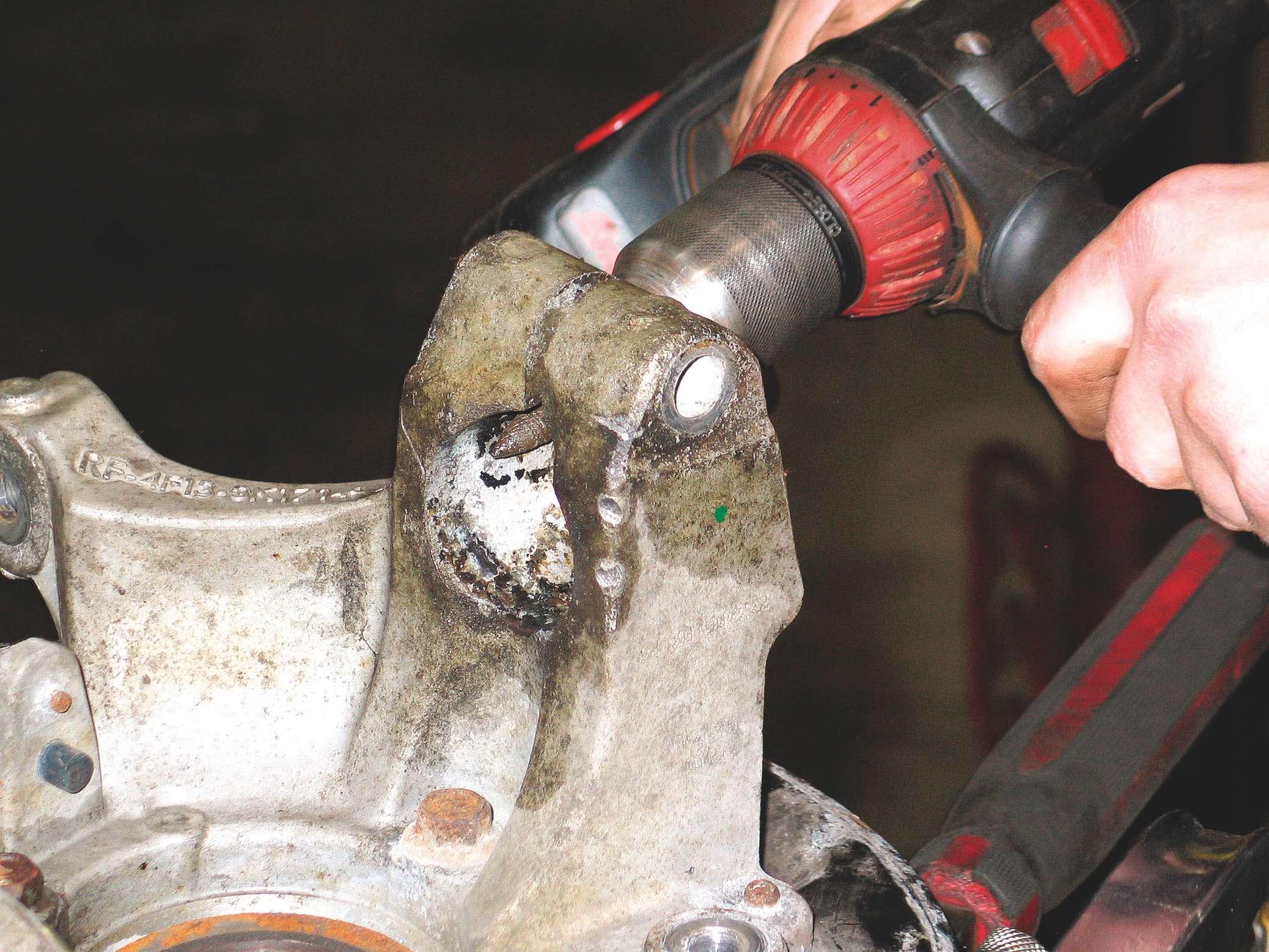
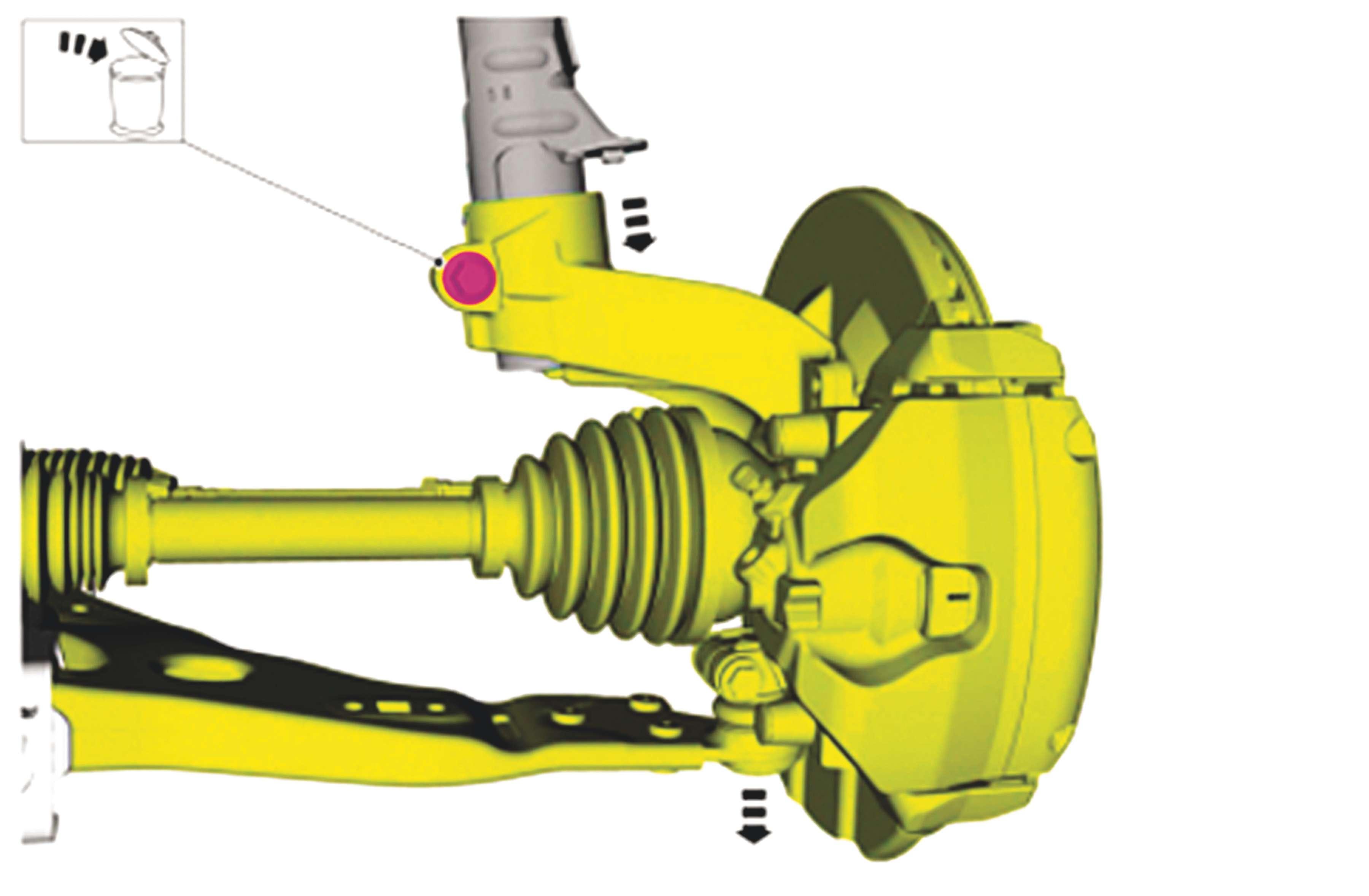
Disconnect the lower strut mount. Depending on design, this may involve either a two-bolt bracket that’s welded to the strut body, engaged onto the knuckle upright; or a tube-through mount where the bottom of the strut tub is captured in a split bore at the top of the knuckle, secured with a horizontal pinch bolt.
With the pinch bolt removed, you will likely need to “persuade” the tube from the knuckle
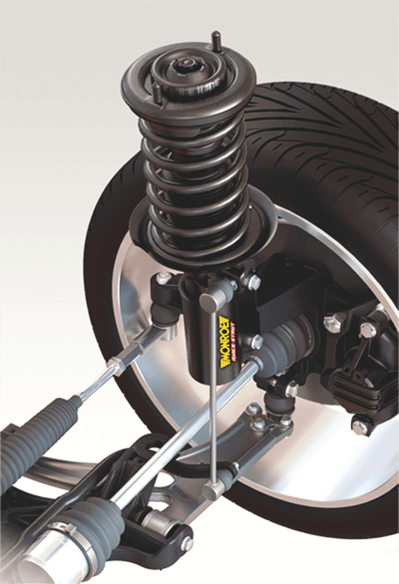
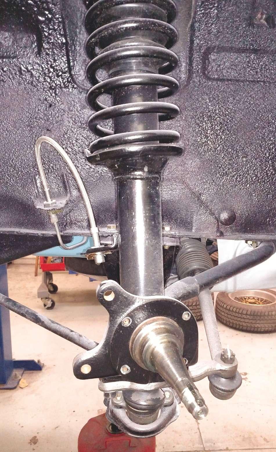
A front strut assembly is responsible for supporting vehicle weight, damping suspension travel and steering axis rotation via the upper bearing. Any condition issues diagnosed including spring, damper or upper bearing problems is cause for either rebuilding and replacing individual components or replacing with a time- and laborsaving compete ready-to-install assembly.

by striking the knuckle downward with a brass hammer.
Depending on suspension design, this might also require lower ball joint disengagement, or, once the upper strut mounting nuts have been removed, you may be able to wiggle the tube from the knuckle. If possible, the lower strut mount should be free before you remove the upper three strut mount nuts.
NOTE: You may encounter older strut designs that feature the strut tube with an integrated lower bracket that secures to the steering knuckle with two vertical bolts, accessed from the If the lower strut mount features a slip-in design and the collar reveals corrosion or burrs, in some cases it may be necessary to underside of the steering arm remove the steering knuckle in order to dress the collar, using a (the Datsun 280Z is an example). pneumatic or electric power tool and abrasive bit.
With the lower strut mount free, remove two of the three upper mount nuts and loosen but do not remove the third nut (if the design features only two nuts, remove one and loosen the other). This prevents the strut from dropping. While holding the strut with one hand, remove the remaining top nut and remove the strut assembly from the vehicle.
NOTE: Do not loosen or remove the center nut that secures the strut’s piston rod.
If you plan to replace only the strut unit while maintaining the upper seat, bearing and coil spring, once the strut assembly Once the lower strut mount fasteners have been removed and is removed from the vehicle, the lower mount has been dislodged from its mount, remove wipe the bulk of dirt and grim two of the upper mounting nuts and loosen the remaining tower mount nut. This readies the strut for removal with the from the assembly and wear remaining nut insuring that the strut won’t drop unexpectedly. safety glasses. Using a quality coil spring compressor designed for strut strut assembly faces in a safe direction, aimed service, engage the tool jaws onto the coils, as away from people, vehicles or equipment. close to the top and bottom as possible. The Before beginning disassembly, use chalk to tool should be either wall-mounted or solidly place matchmarks along the upper hat, spring secured to a large bench vise. To minimize and main body to use as a reference during the danger of accidental and unexpected coil reassembly. spring release, make sure that the top of the With the coil spring captured solidly, begin


A few older strut designs may feature an integrated spindle and lower connection that secures the bottom of the strut built-in base to the steering arm via two bolts that pass through the bottom of the steering arm and are threaded into the strut’s spindle assembly base. The example seen here is from a 1977 Datsun 280Z.

to compress the coil spring until spring pressure at the top hat is removed. Use an impact wrench to loosen and remove the top nut that secures the upper hat and bearing assembly and spring. If the shaft spins and prevents the nut from turning, examine the upper tip of the piston rod. If it features a male or female hex, you can engage a box wrench or hex bit to hold the rod steady while loosening the nut with a box wrench.
Remove the upper hat/bearing assembly and slowly and carefully relax the spring and remove the spring from the strut. Remove the boot and rebound bumper. If the boot and/ or bumper are damaged, plan to replace with new parts.
Always replace all mounting hardware, including upper tower nuts, upper piston rod nut and lower mount bolt(s).
Compare the new strut to the original to verify length and mounting designs.
Discard the original strut according to state and local regulations.
If the new strut has been stored horizontally for a long period (and if the strut is not a gas-charged design), initial movement of the piston rod may seem soft. You can easily prime the strut by compressing and releasing the piston rod a few times until the expected resistance is felt.
In some older designs, the strut tube and lower spring seat are to be re-used by removing the shock cartridge from the strut tube. This may be secured with a thin profile, large diameter hex nut. If this is the case, plan to replace the hex nut, since it’s likely that you’ll damage the original during removal.
Before assembly of the strut package begins, lubricate the exposed piston rod in the area where the rebound bumper will be located, using wheel bearing grease, silicone grease or lithium grease. Depending on the strut brand, a piston rod lubrication recommendation may be included in the instructions.
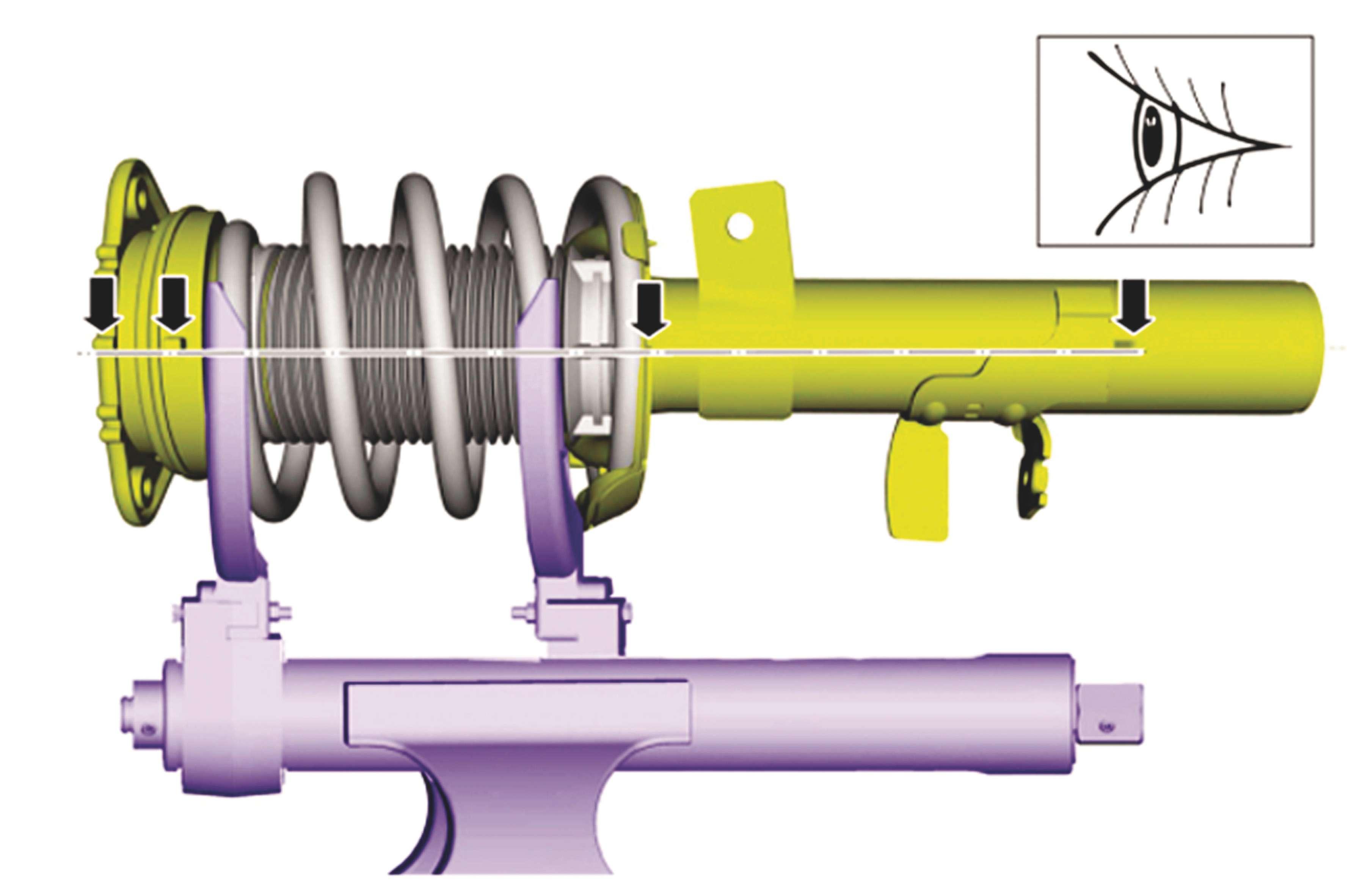

If rebuilding the strut assembly, prior to disassembly, place matchmarks on the strut hat and body. This will provide a clock-position reference to ensure top-to-bottom mount alignment.


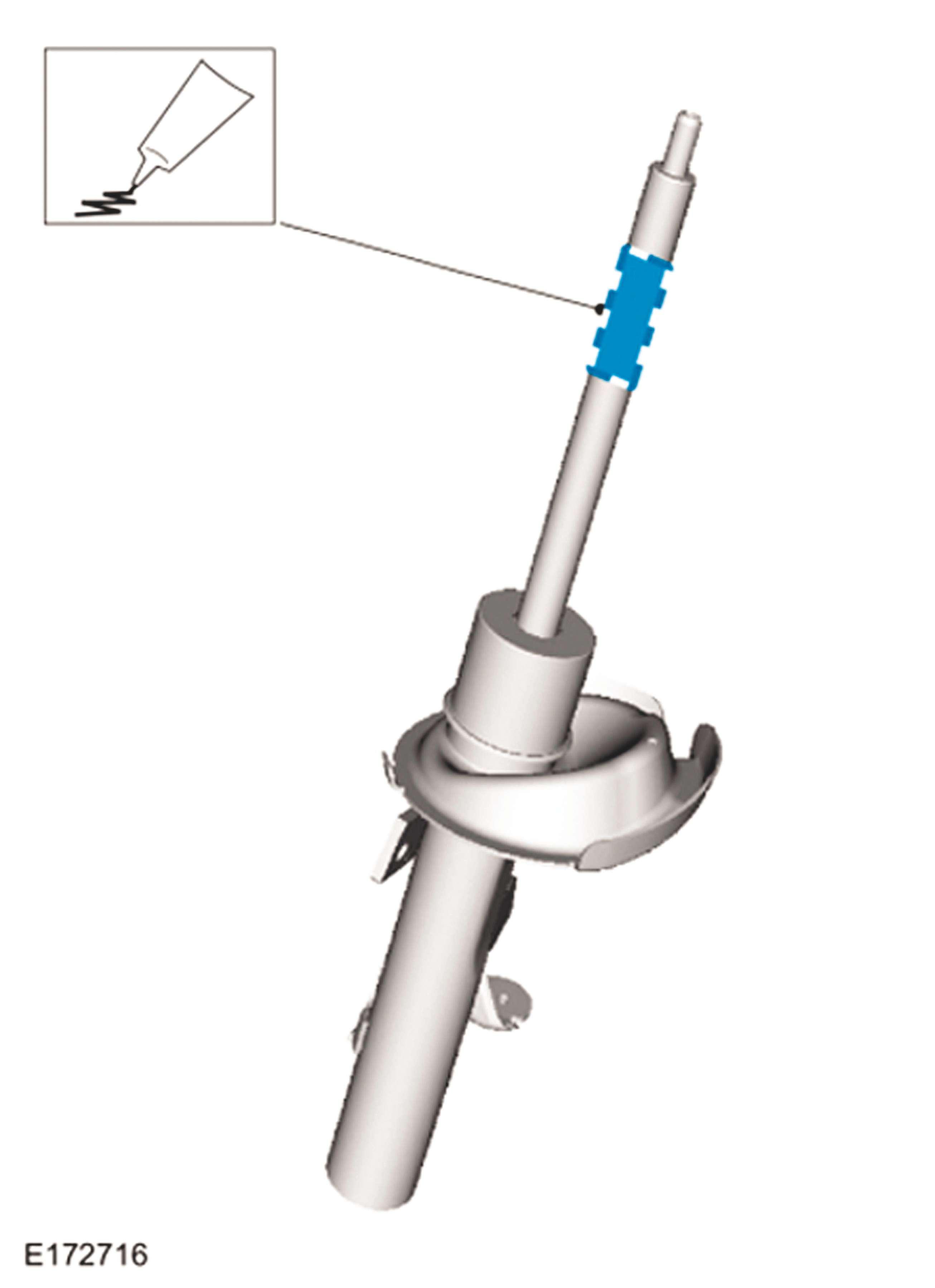
If the strut is to be assembled, be sure to apply silicone grease to the piston rod to allow for smooth bumper movement.
Inspect everything
Closely examine the coil spring, checking for cracks, severe rust or heavy nicks that might act as stress risers. If damage is found, replace the spring. If the strut features a replaceable cartridge, be sure to clean the lower spring seat to remove any debris or rust. Again, if the lower spring seat is badly rusted, replace the strut body. If any dents are found on the strut tube, the strut body must be replaced, as any deformation in the tube can interfere with internal piston and seal travel.
If the coil spring features rubber or plastic isolators at the upper and/or lower coils, replace with new if damaged. If using a new spring, be sure to install these isolators to the new spring.
Install the rebound bumper, in the correct orientation, to the piston rod. Carefully compress the coil spring and pace it over the tube, registering the lower coil in the correct and originals clock position. The lower spring seat should feature a positive stop where the lower end of the spring seats.
Compress the spring far enough to allow installation of the boot and upper assembly. Insert the boot and upper assembly, registering the piston rod tip through the upper hat. Install the new piston rod nut as far as you can to engage at least half of the nut thread depth.
Referencing the previous matchmarks, align the spring and upper hat assembly in the correct clock position.
While holding clock position, slowly relax the spring tension until the upper hat assembly secures the spring. Verify that the upper mount bearing is free to rotate. Snug the

When dealing with a lower strut mount that features a slip-in design with a pinch bolt, it’s not uncommon to be faced with an extremely stubborn removal of the strut tube from the steering knuckle’s collar. If the collar has been hammered loose, the collar may require dressing to accommodate the new strut installation.


During strut assembly installation, make sure to always install new upper tower-to-strut nuts. piston rod nut to further secure the assembly. Avoid using an impact wrench to tighten the piston rod nut, as this can easily cause the rod to spin. Fully release the spring compressor and remove the strut from the tool.
Always use a new top piston rod mounting nut, whether reinstalling the original strut or replacing with a new strut. New struts will usually include a new piston rod nut. If necessary, new nuts may be obtained from your ride control supplier. Thread integrity and overall strength is critical, since a nut that fails or loosens will allow the strut piston rod to oscillate needlessly and potentially fail.
These nuts also often feature a “locking” design in the form of a slightly distorted upper inside diameter (often referred to as a self-locking or “stover” nut) or a nylon insert that prevents accidental loosening. These nuts are considered non-reusable and must be replaced.
Caution
Use caution when loosening or tightening the upper piston rod shaft nut. The strut’s piston shaft may rotate as the torque is applied to the nut. If the strut is to be reinstalled, do not use an impact wrench to remove the nut, as this may cause the shaft to rotate or spin quickly, which can gall the
threads and damage the internal seals via friction and heat. When installing a new or used strut, by the same token, do not use an impact wrench. Strut shaft upper tips vary by design, but a provision for holding the shaft in place to prevent rotation should be featured.
This allows you to use an open-end or box wrench to hold the shaft stationary while turning the nut.
In some cases, a specialty wrench will be required to secure the shaft. Never use pliers or a vise-grip to secure the piston rod in place, as this will create burrs on the shaft, which will result in internal damage.
Of course, in certain cases, a technician will be forced to do whatever he or she must do in order to remove an original worn or damaged strut. However, never use pliers to secure the piston rod on any strut that will be final-installed.
Installation
If you plan to install a new complete strut assembly such as Monroe’s Quick Strut or Gabriel’s ReadyMount strut, insert the top of the assembly into the strut tower, aligning the three upper mounting studs to the tower holes and snug-install one upper new nut. Do not fully tighten or install the remaining nuts yet. This allows the strut to pivot freely while engaging the lower strut mount, which reduces the risk of damaging the upper strut bearing.
Install the lower strut mount, installing two new bolts to secure the strut bracket to the knuckle; or in the case of a slip-tube lower body, engage the tube at its correct depth and install a new pinch bolt.
Fully torque the lower mounting bolt(s). Install any accessories that were previously removed from the old strut body such as ABS wires, brake line and/or anti-sway bar link. Torque these bolts to the specified values.
Install the wheel, referencing the matchmarks to ensure that the wheel is installed in its original clock position.
Lower the vehicle, loading the suspension. At this time, fully tighten and torque to value the upper strut mounting nuts that secure the strut to the tower. Also fully torque the upper piston rod nut. Again, hold the piston rod steady while tightening its nut, taking advantage of the piston rod’s top male or female hex. Waiting until the suspension is loaded to torque the upper nuts ensures full strut engagement inside the tower and eliminates the risk of damaging or weakening the upper strut mounting studs, as opposed to pulling the weight of the strut and control arm upwards as
Gabriel offers their ReadyMount line of replacement strut complete assemblies, eliminating the need for disassembly or assembly.
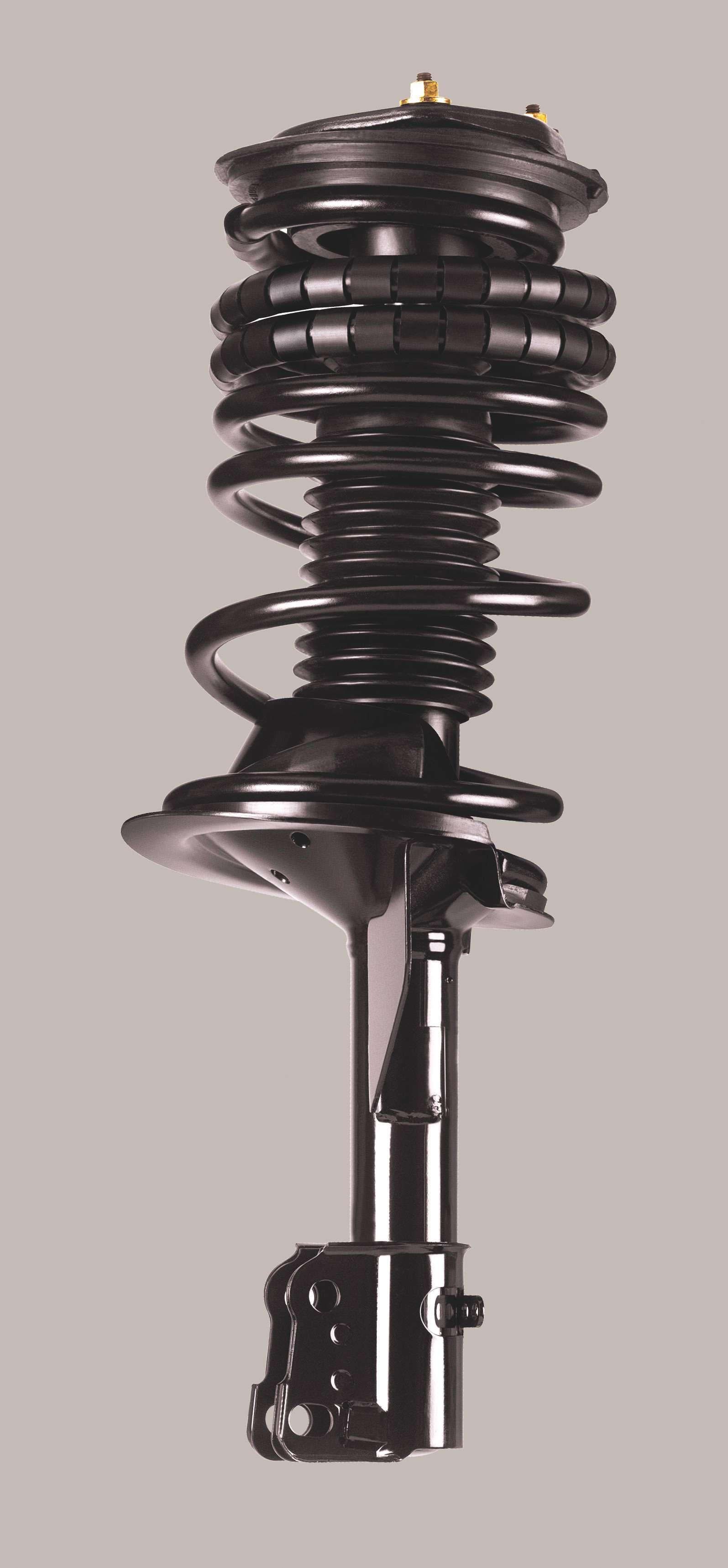


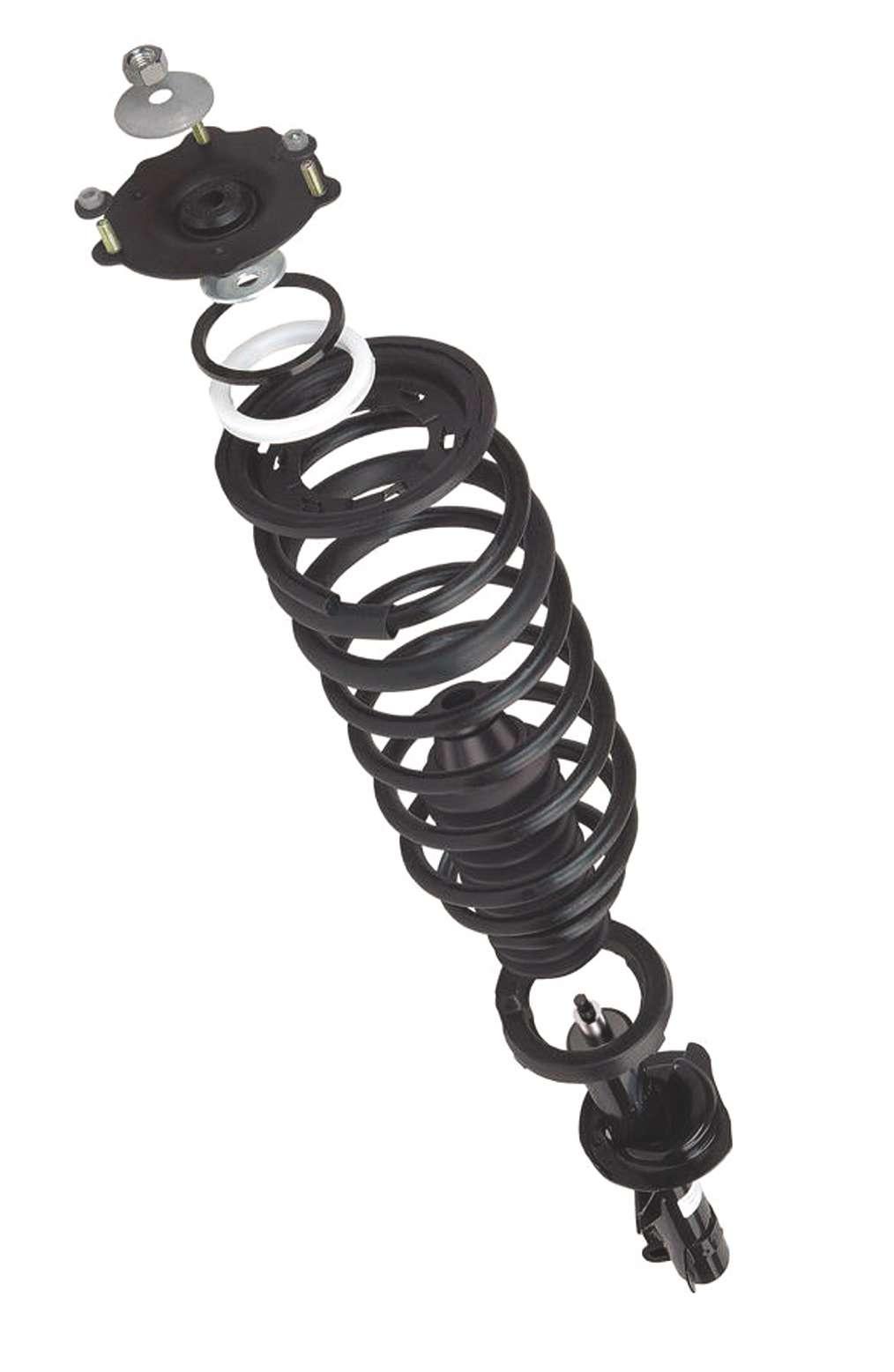
A ready-to-install complete strut assembly, such as the Monroe Quick Strut assembly exploded view shown here, includes all new components, with no need to replace individual parts such as upper bearing, the strut unit, spring, etc. All new mounting fasteners are included. the nuts are tightened. This also ensures that the piston rod is fully engaged on its threads.
Always replace struts in axle pairs. If the right or left side strut is new and the opposite strut is aged, a considerable difference in ride control can occur, leading to poor and often unpredictable handling and braking.
If a strut on one side of an axle has worn or failed, the opposite side strut is likely in the same condition. This may seem like common sense, but consumers on a budget may be reluctant to spend money for something that they assume is not needed. Stand your ground and insist on replacing the pair, making it clear that this is in their best interest in terms of safety. Always replace in axle pairs.
Notes on the lower mount
As mentioned earlier, the most common styles of lower strut mounting design may feature either a bracket that secured to the upright and cinched with two bolts, or a slip-fit that enters the knuckle upright’s split bore, with a pinch bolt that creates a tight interference fit.

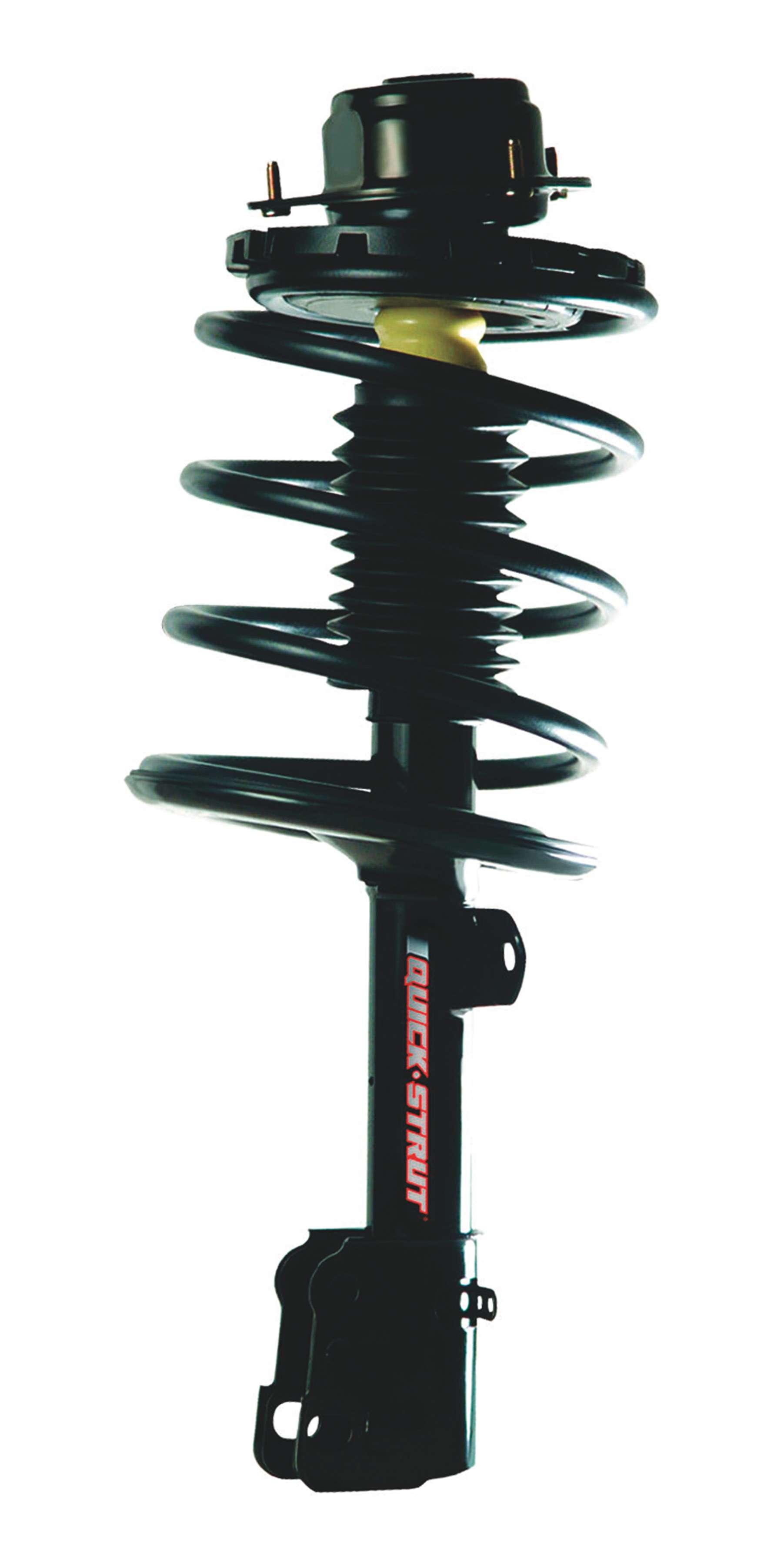
Monroe’s line of Quick Struts are also complete assemblies, with OE-spec spring and hardware but with enhanced damping.
When removing a strut assembly that features a slip fit lower mount, after removing the pinch bolt, it’s likely that a tight interference fit remains, making it difficult to remove the lower strut body from the upright.
Using a wedge tool, the split bore may be separated slightly at the gap in an effort to spread the bore. Adding a penetrating oil may help as well.
Using a brass or aluminum hammer, striking the split bore housing downward may help to dislodge the strut tube body, in addition to pivoting the spindle/upright unit across the strut tube.
Before installing a new strut assembly that features a slip-tube-to-split collar knuckle, make sure that the split tube bore is clean and free of burrs that may have been created during removal.
A honing stone or a grinding stone on a pneumatic die grinder can be used to clean the bore. During reassembly, always install a new pinch bolt and nut.
Before inserting the lower strut tube into the upright’s pinch bore, apply a film of antiseize in the bore. This will aid in assembly and should ease future removal.
If the lower strut mount features a two-bolt bracket, before installing the new strut, clean the upright surfaces to remove any rust and/ or burrs.
Only use sandpaper or emery cloth to clean the upright’s mating surfaces to avoid removing excess metal. Always install two new bolts and nuts to secure the lower mount.
The two-bolt lower bracket bolt holes in both the upright and strut bracket will likely feature enough tolerance to alter the wheel’s camber angle.
Always perform a wheel alignment following front or rear strut service. Even if the lower strut bracket holes are not elongated to accommodate camber adjustment, the holes may provide a minimal amount of adjustment.
In some cases, such as the Ford Taurus series, it’s very common for the pinch bolt that secures the lower strut tube body to the knuckle to be badly rusted in place. It’s not uncommon to fracture and break this bolt when attempting removal with a strong impact wrench.
Rather than risking this, first place a matchmark on the bolt head and knuckle. This will provide a reference to see if the bolt is turning when you do attempt removal. If time allows, let the oil soak overnight before wrenching.
If the bolt does not begin to rotate, apply heat, being careful not to damage adjacent surfaces. Once the bolt area is hot, apply more penetrating oil, allow the area to cool for a few seconds and attempt to remove the bolt. It may be necessary to repeat these steps several times until the corrosion breaks down enough for bolt removal.
If the bolt does break, you’ll need to drill it out. In the process, you’ll unavoidably drill out the female threads in the knuckle. In this case, you’ll need to install a new, longer bolt and a nut to complete the installation. Be sure to use a grade 8 bolt and nut. Consider using a lock washer on the nut side.
NOTE: Some vehicles, such as a 2010 Ford F-150, features front shocks with captive coil springs that at first glance may appear as struts.
However, this suspension features upper and lower control arms. The damper assembly is simply a coil-over shock absorber with an upper spring seat and a lower eyelet style mount and is not considered a strut.
Suspension diagnosis
Vehicle leans: If the vehicle tends to exhibit excessive lean in turns, and during braking or acceleration, check the condition of the coil spring(s), strut assemblies and damaged, worn or missing anti-sway bar bushings/ links. A worn strut assembly may feature a worn or broken coil spring and/or a worn damper, whether the damper is of hydraulic or hydraulic/gas design.
Front end shimmy: Suspects include upper ball joint (if so equipped), upper control arm bushings (if so equipped), lower control arm bushings, inner tie rods, the hub assembly, and a FWD driveline (CV shaft assembly). Check tires for proper inflation. Underinflated tires can cause a shimmy.
Also inspect for improper tire size matching on the same axle. Tires of different diameters,


and/or suspension components.
Excessive wear found only at the outer tread areas and shoulders is likely the result of aggressive driving in turns and curves, inadequate wheel camber angle, or a combination of both.
Excessive steering wheel
play: Potential faults can include a worn or damaged steering rack, inner and outer Lower mounting fasteners must always be replaced, whether this features a single pinch bolt (as shown) or two lower bracket bolts. tie rods, hub assembly, lower or tires of different brands or even different control arm bushings, upper control arm tire models within the same brand, can cause bushings (if so equipped), or CV shaft joints/ this issue. assemblies.
Uneven or premature tire wear: After Always verify a customer complaint regardchecking the obvious concern for proper tire ing steering wheel play. inflation pressure, this issue can be caused If the vehicle was previously serviced, and by any of a number of variables, including the steering wheel was removed at any point, incorrect wheel alignment, worn control arm check for in-out play which can indicate bushings, the strut assembly, inner and/or that the steering column shaft nut was not outer tie rods, lower control arm ball joints properly tightened. and upper arm ball joints (if so equipped). Steering wheel vibrations: Vibrations felt
Diagnosing tire wear is a subject unto through the steering wheel can result from a itself. Premature tire wear can result from range of issues, including wheel imbalance, the use of tires that feature (relatively) softer radial tire force variation, CV shaft assembly tread compounds, as found in many high issues including worn/damaged CV joints performance, high-speed-rated tires, as well and/or the loss of a damping device from as tires that are specifically designed for cold a CV shaft, loose/worn hub bearings, or weather snow/ice use. improper brake caliper action resulting from
Softer compounds tend to wear faster, brake rotor runout or a dragging or sticking especially on dry road conditions where the brake caliper. coefficient of friction is greater as opposed to If brake pedal bounce is felt in addition, wet, snow-covered or ice-covered surfaces. suspect brake rotor runout issues.
By and large, premature tire wear, especially Note that improperly tightened wheel where tread wear appears uneven, is usually fasteners may also contribute to a distorted the result of improper inflation, incorrect brake rotor. wheel alignment or worn/damaged steering Grinding or cluncking noises: Unusual
noises emitting from the front end of the vehicle may involve a wide range of potential issues.
• Upper strut mount (mount lose or mount bearings worn/dry/damaged). • Coil spring damage (cracked, failed spring) or an improperly seated coil spring. • Control arm bushings • Strut assembly itself (worn/damaged damper, piston shaft, spring, lower strut mount, improperly assembled strut) • Inner and/or outer tie rods • Anti-sway bar bushings/links (damaged, worn or missing) • Hub bearing assembly • CV shaft assembly • Brakes (loose or sticking brake caliper/ pads; a foreign object such as a small rock wedged between a pad and rotor) • Wheel clearance (if a non-original wheel with incorrect backspacing or diameter has been installed, check for clearance at the caliper)
Front end pulls right or left: If a directional pull is present, first check all tires for correct inflation pressure. Also check tire sizes for mis-matched sizes on the same axle, and for mixed tire brands/models on the same axle. Inspect wheel alignment angles, since incorrect toe, camber or caster angles can easily result in a pull.
Suspension components of concern include upper strut mounts (worn, dry or failed strut mount bearings can affect steering axle dynamics, reducing the right or left wheel’s ability to follow steering wheel commands).
Other suspect components may include control arm bushings, coil spring condition (weak, sagging spring, improperly installed spring or damaged spring), lower ball joints, upper ball joints (if so equipped), and inner/ outer tie rods.


This bulletin applies to BMW E82, E88 (1 Series), E90 and E93 (3 Series) vehicles equipped with the N54 engine and produced up to 2-27-2010. The A/C system may be producing no or minimal cooling output.
The clamp on the charged air pipe may be rubbing against the A/C pressure line on the compressor-condenser when the engine is running, causing damage to the pressure line.
Check for any damage around the compressor-condenser pressure line and the charged air pipe.
If damage is found, evacuate the refrigerant in accordance with the REP 64 52 “... instructions for opening and replacing parts in the refrigerant circuit for drawing off, evacuating and filling the air conditioner system.”
Remove the rear left charge air duct. Replace the compressor-condenser pressure line with refrigerant line P/N 64 50 4 239 966. Install the rear left charge air duct.
Refill the system with the specified amount of refrigerant, following the REP 64 52 instructions.
Make sure that the clamp on the charged air pipe is positioned to prevent rubbing contact. Verify that the gap between the radiator hose connection clamp and the screw head of the charged air pipe clamp is at least 60 mm.
Buick/Chevy FUNKY FUEL GAUGE
Some 2008-2009 Buck LaCrosse and Allure, and Chevy Impala vehicles may exhibit an inaccurate fuel gauge and/or DTC P0461.
Prior to removing the fuel level sending unit from the tank, perform a terminal drag test on terminals B, D and H in the 8-way connector at X405. If a terminal concern is found at X405, replace the terminal as necessary. Interference is suspected between
BMW A/C GLITCH
the end of the float arm where it is attached

to the sending unit and the convoluted tubing that is part of the sending unit. To inspect for the potential interference it is necessary to compress the fuel sending unit on the bench to the same height as it is compressed in the fuel tank.
NOTE: DTC P0461 also can be customerinduced by refueling after only 50 or 60 miles or less.
Chevrolet COMMUNICATION BREAKDOWN
This bulletin applies to 2010-2013 Chevy Camaro models. In rare cases, a customer may report an intermittent fluctuation of IP gauges, no crank, SES light on, or various IP warning indicators or messages. Technicians may find that there is no communication to various High Speed LAN modules. Communication to control modules may be random and could change during Closely check the engine inspection. Any wiring harness under the ECM for any chaffing. of these concerns could be caused by a short to ground or an open on either of the two High Speed LAN circuits 2500 and/or 2501.
There are two locations on the vehicle to inspect, depending on what vehicle options are present.
The first area of concern is the engine
wiring harness under the ECM. Check for possible chaffing of this harness on the inner fender panel. If chaffing found, repair the wire(s), install protective conduit on this area of the harness and relocate the harness away from the panel. The second area of concern relates to vehicles equipped with an automatic transmission. A HSLAN circuit terminal Check the vehicle’s TCM connecmay not tor terminals for proper seating. be seated properly in the round TCM connector located on the transmission. Inspect the TCM connector for any data line circuits that may not be fully seated in the plastic connector. If this concern is found, inspect the condition of both halves of the connector as well as both the male and female terminals.
If the female terminal was not seated correctly, push on the wire until the terminal clicks back into position. Lightly tug on the wire to verify seating. If the male terminal or the TCM half of the connector is damaged, the entire TCM will require replacement. This module is internal to the automatic transmission assembly.

Chevrolet THE PIN TOOK A WALK
While performing a front-wheel alignment on a 2008-2012 Chevy Colorado, you may notice that the upper control arm bracket alignment pin is missing. This pin serves as a pilot for the alignment cam when adjusting camber and caster. It’s unlikely that someone stole it. The factory simply made an oops.
If the pin is missing, simply make-do by inserting a 1/4-inch dowel rod, punch or drift as a temporary aid to properly center the cam to the bracket, while making adjustments and while torquing the control arm nuts.
Mercedes-Benz SHIFTY MERCEDES-BENZ
If the owner of a Mercedes-Benz vehicle equipped with the 7G-Tronic (NAG2) automatic transmission complains of an uncomfortable/rough 1-2, 3-2 and 2-1 gearshift, this may be due to the specific gear not being fully adapted or there could also be a mechanical cause as well.
1. Reproduce the complaint and identify the affected shifts using Star Diagnosis. 2. Print out adaptation data in the form of a transmission control unit log (do not reset the adaptation values). 3. Re-adapt the problem shift using the adaptation process in Star Diagnosis and print a post process transmission control unit log.
For downshifts, the vehicle must coast to a stop without braking in order for adaptation to occur. For upshifts, the vehicle must be driven and shifted within the valid torque window (green zone in torque display in Star Diagnosis). If the condition still exists after adaptation, compare adaptation values before and after the adaptation test drive. If the values for the filling times of these shift operations are close to the negative limit of -20 cycles (between -15 and -20), but move further into the negative with further adaptation, this may have the following cause/remedy:
CAUSE A
An incorrectly installed retaining ring for return spring B1 or B3.
REMEDY 1. Remove the transmission.
These photos illustrate the differences in the two versions of the B1 and B3 multi-disk brake.
Carefully verify the correct positioning for the anti-twist locks for the thrust bearing. 2. Disassemble multi-disc brake B1 and B3. 3. Remove/install/replace the retaining ring and disc spring. NOTE: There are two different versions of the
B1 and B3 multi-disk brake. It is essential to ensure that the retaining ring is ordered correctly. 4. When assembling, ensure that the antitwist locks are correctly positioned. 5. Completely reset all adaptation data. 6. If shift quality complaints still occur, the affected shifts must be adapted before further steps are taken.
CASE B
Warped discs of the B1. This can be determined by placing them on a flat surface and inspecting.
REMEDY 1. Replace discs of B1, disc spring and retaining ring. 2. Completely reset all adaptation data.
PARTS Qty. Part 2 Circlip (snap ring) for variant A and C P/N
A220 994 03 40
2 Circlip (snap ring) for variant B and D A001 994 18 40
2 Disc spring A220 993 02 26

Dodge/Chrysler/Jeep MOPAR STEERING ANGLE SENSOR
This bulletin applies to 2007 Dodge/Chrysler/Jeep vehicles built on or before 4-12-2007, including Wrangler, Sebring, Nitro, Caliber, Compass and Patriot. The subject involves selectively
erasing and reprogramming the SAS (steering angle sensor) with new software.
The owner may experience an illumination of the ESP (electronic stability program) lamp on the instrument cluster.
The ESP lamp illumination may be due to DTCs C121A (steering angle sensor not initialized) and C2205 (steering angle sensor internal).
This condition, and the DTCs, may be intermittent.
If the DTCs occur during a drive cycle, then the ESP lamp will remain illuminated until the end of that drive cycle (key off).
Using a StarSCAN with the appropriate diagnostic procedures available in TechCONNECT, verify that all engine systems are functioning as designed. If DTCs are present, record them and repair as needed before proceeding.
SPECIAL TOOLS NEEDED Battery charger CH9401 StarSCAN tool CH9404 StarSCAN vehicle cable CH9409 StarSCAN documentation kit CH9410 StarSCAN Ethernet cable, 12 ft. CH9412 StarSCAN software update device kit TechCONNECT PC or equivalent Latest StarSCAN software update CD
Before performing this repair, the operating software in the StarSCAN must be programmed with software release level 7.04 SP1 or higher. The software level is visible in the blue header at the top of the StarSCAN screen.
1. Open the hood and install a battery charger. Verify that the charging rate provides 13.2 to 13.5 volts. Set the battery charger to continuous charge. Do not allow the charger to time-out during the flash process. 2. Connect the CH9410 ethernet cable to the
StarSCAN and the dealer’s network drop. 3. Connect the CH9404 vehicle cable to the
StarSCAN and the vehicle. 4. Power-on the StarSCAN. 5. Retrieve the old ECU (SAS) part number. 6. Using the StarSCAN at the Home screen, select ECU View. Touch the screen to highlight the ECU (SAS) in the list of modules.
Select “More Options.” 7. Select “ECU Flash.” 8. Record the part number at the top of the
“Flash PCM” screen for later reference. 9. Select “Browse for New File” and follow the on-screen instructions. 10. Select “Download to Scan Tool.” 11. Select “Close” after the download is complete, the select “Back.” 12. Highlight the listed calibration. 13. Select “Update Controller.” 14. When the update is complete, select “OK.”
Clear any DTCs that may have set as a result of reprogramming.
Volkswagen A PROBLEM THAT SUCKS
If a 2013 Volkswagen Passat shows a MIL on with DTCs P0410, P0411 or P1423, this may be caused by a broken or cracked vacuum hose due to temperature variations.
Sounds like time to break out the old smoke machine.

Mercury GROOVY HOOT
Some 2007- 2008 Mercury Mountaineer vehicles
equipped with a 5.4L engine may exhibit a front end accessory drive (FEAD)-related high pitch metallic whistle/hoot noise after a cold soak in ambient temperatures below 40 degrees Fahrenheit. This noise may be caused by the grooved nylon FEAD idler pulley.
Replace the nylon idler pulley with P/N 6L3Z-6C348-A.
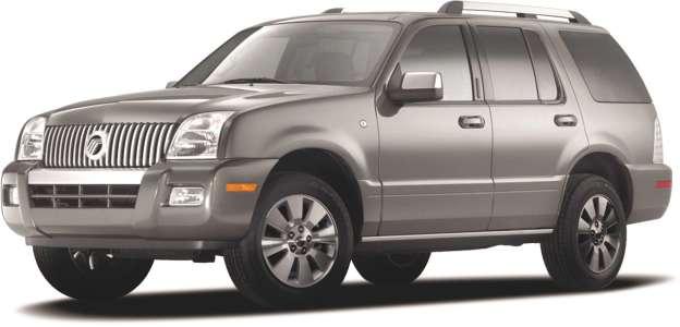
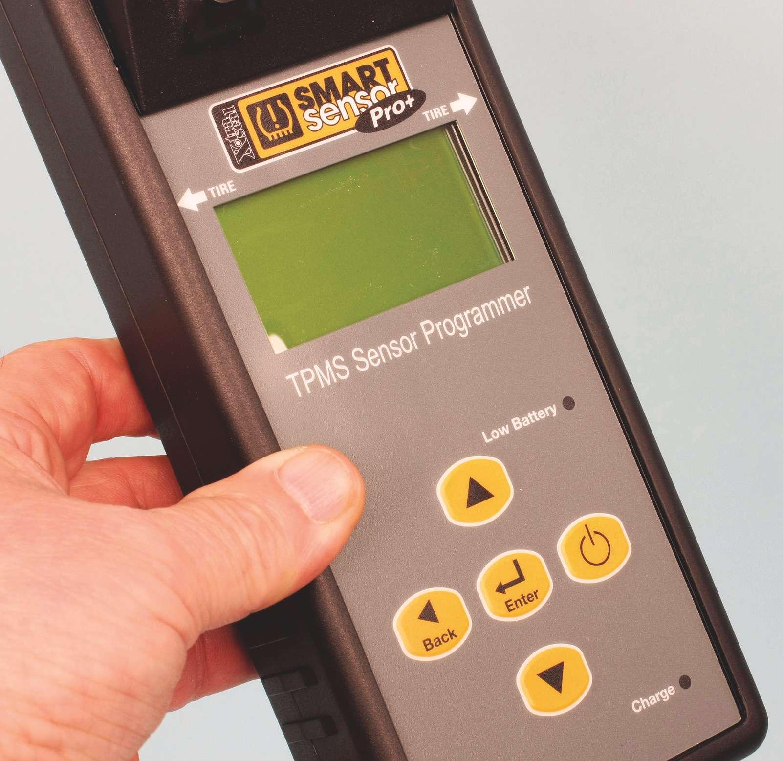
X-tra Seal Smart Sensor Pro+
31 Inc. makes TPMS service easy
By Mike Mavrigian
The Smart Sensor Pro+ diagnostic/programming tool from 31 Inc. is a marvel of efficiency and simplicity. The learning curve is nearly zilch. If I could learn to use this tool in a matter of minutes, anyone can.
One very nice surprise is that the diagnostic/relearn/programming tool is free, as long as you buy a handful of 31 Inc.’s universal Smart Sensors. I was told by the firm’s rep, John Rice, that the distributor makes the call in terms of an initial sensor purchase, but it’s likely in the very affordable realm of eight to 10 sensors. No catch and no fine print — buy a few sensors and the tool is free. Now that’s elevating the cool factor to a level that will make you smile.
Among the Pro+ tool’s many features, it also allows you not only to read existing sensors (tire pressure, temperature, etc.), but to also relearn/re-program the tire pressure monitoring system ( TPMS), in cases where tires are rotated and/or sensors are replaced.
Since many Asian vehicles require plugging into the OBD II port, the kit includes a handy OBD II module for re-learning the systems on these vehicles.
Do you have a fear of updates? Rather than forcing you to pay for updates to remain compatible with OE changes or vehicle additions, the tool includes a lifetime of free online updates.
The universal programmable Smart Sensors are offered in both frequencies (315 MHz and 433.92 MHz), with your choice of rubber snap-in stems or aluminum clamp-in stems. To make life easier, the 315 MHz sensors are color coded green, while the 433.92 MHz sensors are color coded brown for easy identification.
Sensor scan
1. Select vehicle make, model and year. 2. Highlight SCAN SENSOR. 3. Hold the tool against the tire sidewall, next to the air valve and press ENTER. The tool will trigger the sensor and will display
Controls are simple and intuitive. There’s absolutely no steep learning curve required. The term “user friendly” definitely applies.


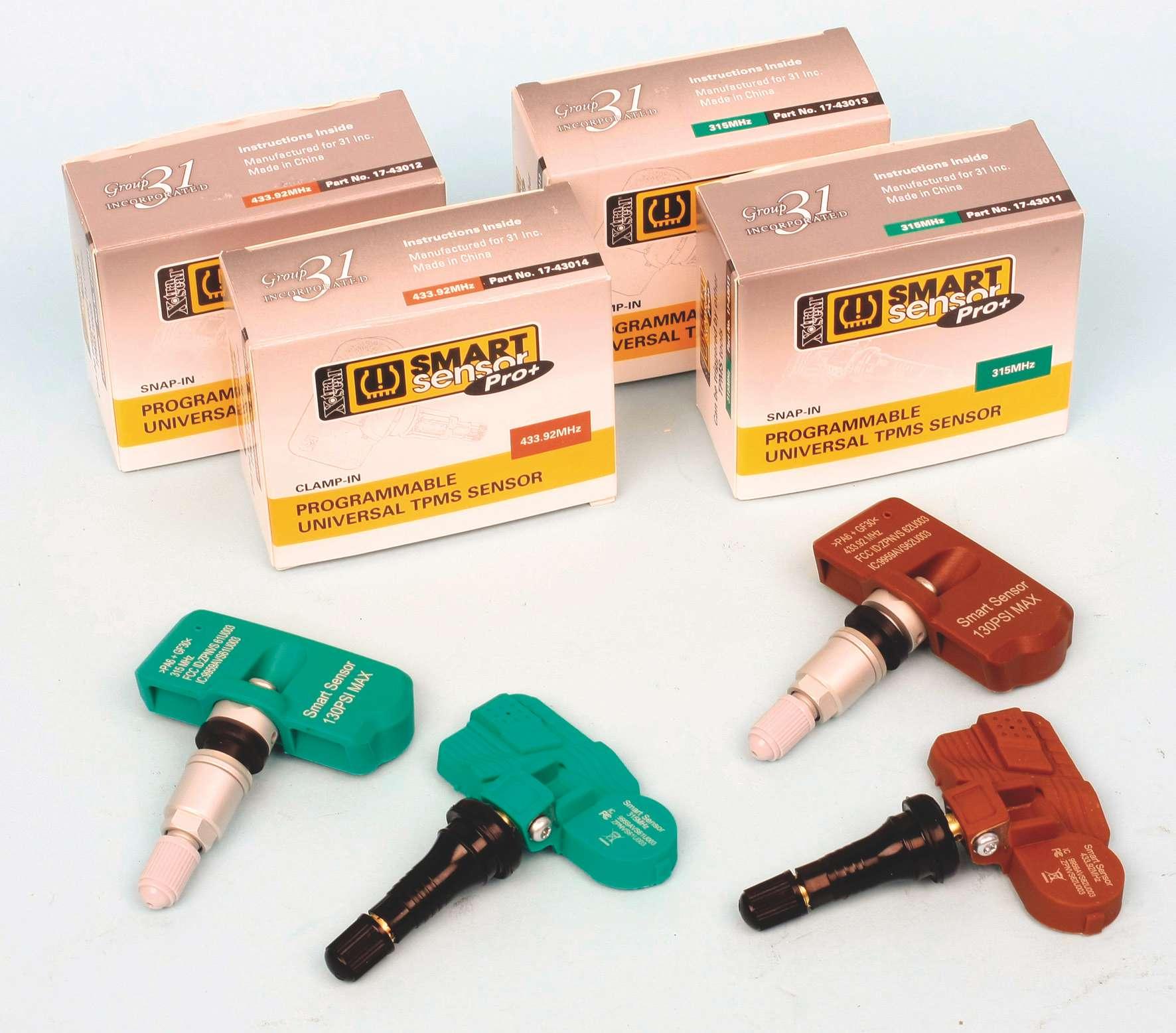
The programmable Smart Sensors are available in both common frequencies (315 MHZ and 433.92 MHz), in both snap-in rubber-stem and clamp-in aluminum-stem versions.