

SPECIFICATION GUIDE

TABLE-OF-CONTENTS


HEIGHTS & WIDTHS
HEIGHTS:
mm (41 in) 1350 mm (53 in)

* Other heights available depending on ceiling height
WIDTHS:
mm (2 ft)
900 mm (2.9 ft)
1000 mm (3.3 ft)
1200 mm (4 ft)

ION HEIGHTS


average male height: 5'9" (69")
average female height: 5'4" (64")
ALUMINUM
CONNECTOR POSTS
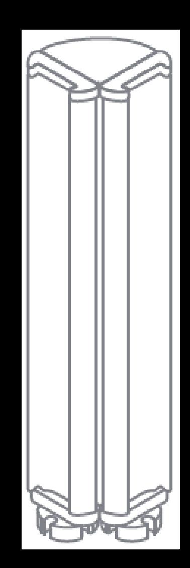
L-Shaped Post
Connects two panels at 90° angle

T-Shaped Post
Connects three panels at 90° angle
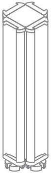
X-Shaped Post

I-Shaped Post

Connects four panels at 90° angle End Post
Connects two panels at 180° angle
Is placed on the end of a panel that does not connect to another panel
ION COMMON PARTS
Horizontal Track
A track where cantilevers and small brackets clip into the panel to support work surfaces. This should always be at work surface height.
Base Panel - With Raceway
A panel that has power running through it, and has the horizontal track to connect to work surface.

Accent Panel
Raceway with Cut-Outs
A powered part of the panel where outlets are accessible to the user.

Glass Panel
A 12" glass panel that can stack on top of other panels.
A 12" panel that is placed on top of the base panel.
Raceway without Cut-Outs
A powered part of the panel without accessible outlets to the user, usually used to connect power between panels.
Base Panel - To The Floor
A panel that does not have power running through it, but has the horizontal track to connect to work surface.
ION
COMMON PARTS


Hooks into panels and is screwed underneath work surfaces for support, typically spans two panels and two surfaces.
Hooks into panels and is screwed underneath work surface for support.
Is screwed underneath two work surfaces for support, usually in front of cantilever.
Cantilever
Small Bracket
Flat Plate
MILLIMETERS TO INCHES
RELEVANT SIZES
ACE OPTIONS WITHOUT GROMMETS


ACE COMPOSITION

EXPLODED WORKSURFACE
(not to scale)
ION PANEL OPTIONS
IN-STOCK OPTIONS


ION SURFACE OPTIONS
IN-STOCK OPTIONS


XD-1040 NorthAmerican Walnut
XD-1001 Grey
XD-1004 Black
XD-1009 White
XD-1014 Teak
XD-1016 Walnut
XD-1021 Fir
XD-1022 RedOak
XD-1021 WhiteOak
XD-1020 Maple
L
SPECIFICATIONS
Common Parts

Power Module
Allows a panel to be powered through the raceway.

Festoon
Connects one power module to another power module via posts.

Pass Thru Jumper
Spans non powered panels to continue power to another panel.

Base Feed
Connects the building's power from the wall or �oor to the panels.

Ceiling Feed
Connects the building's power from the ceiling to the panels.

Receptacles
Outlets for cubicles.
L
SPECIFICATIONS
Power Modules provide electrical distribution and access for duplex outlets back to back. 24" wide panels can accept only one duplex outlet per side, two total back to back. All other panels can accept two per side, four total back to back. Power Modules "grow" in length with panels of greater width, making panel to panel connections a "standard" con�guration and allowing for "pass through" connections. Each Power Module has locations for up to four jumpers, two at each end. Power Module are included when ordering powered panels.
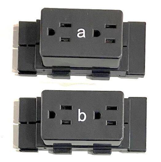
Duplex outlets are available on designated circuits 1 through 4. Each duplex outlet contains two single receptacles (places to plug into) of the same circuit and are speci�ed separately from Power Module. All duplex outlets have black faces. The lettering on outlets for Circuit 1, 2, and 3 is white. The lettering on outlets for Circuit 4 is orange. Outlets snap into the Power Module. Duplex outlets are standard 15 amp outlets.

LSPECIFICATIONS
8 Wire 4 Circuit electrical system contains four circuits. Each circuit is rated at 15 amps/120 volts maximum. Circuit 1, Circuit 2, and Circuit 3 are served by a system neutral and an equipment ground. Circuit 4 is dedicated and is served by its own neutral and ground. Circuit and ground conductors are # A.G.W. (gauge).
All neutrals are #10 A.G.W. (gauge).

L
SPECIFICATIONS
Wiring Anatomy for Ceiling and Base Infeeds
Shown below is a cross section of the metal cable used for 8 Wire 4 Circuit ceiling and base infeeds.
Circuit and ground conductors are #12 A.G.W. (gauge). All Neutrals are #10 A.G.W. (gauge).

LSPECIFICATIONS
This con�guration includes 4 hot wires that correspond to circuits a, b, c, and d. Circuits a, b, and c are general circuits that share a common neutral and ground. Circuit d is considered an isolated circuit because it has its own grounding source and wire that is not shared with other equipment. Circuit d is also considered dedicated because it has its own neutral wire.
The purpose of having its own neutral and isolated ground is to prevent unwanted noise from other devices traveling through the system and potentially causing interruptions. Circuit d is typically reserved for computers. Because Circuit d has its own hot, neutral, and ground wires, it could have a separate source of power known as a UPS (Uninterrupted Power Source).

LSPECIFICATIONS
Typical Electrical Raceway (covered)
Typical Electrical Raceway (uncovered)

21.5" Festoon for X/T/L post
Power Module/ Harness
18" Festoon for I post
L SPECIFICATIONS
Hiring an IT/Networking Team
Every company has very speci�c requirements when it comes to data/networking. When you hire a networking contractor, they will pull lines from the server room and splice their wiring into the networking jacks that �t your needs. Some require one jack per face plate, some require multiple. If electrical and data are coming from the ceiling and are being supplied to more than three workstations, we recommend that each data drop has their own power pole, separate from the power poles used for electrical.
To the right is an example of what a lot of clients use as a data face plate. Your IT Group should supply the data face plate and hardware that works best for your needs. Our raceway covers are silver and our electrical receptacles are black.
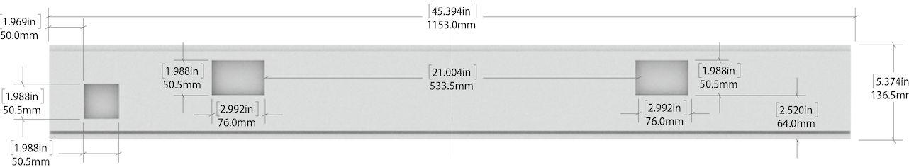
The rectangular cutout is simply a "knockout" in the raceway cover at the base of the panels where your networking contractor can attach any size �ush mount plate. This knockout will need to be punched out during install. Any size will work (larger than the knockout) and you can screw it right to the raceway cover.
Data Plate Speci�cations
Standard kickplates (for 900mm, 1000mm, 1200mm raceways) will have two knockouts/cutouts. The data knockout is 2x2 (50.8 mm) and 1 ½" (38.1 mm) from the bottom of the kick plate.

L
SPECIFICATIONS
Ceiling lnfeeds
Power can be brought from the ceiling down to the workstations via a power pole. This plastic pole slides 6" down into the post (t-post or x-post)of the workstations panels, and can power up to eight workstations.
The standard height of the pole is 12', and it can be cut ahead of time if the ceiling height is known. If not, it can be cut in the �eld. The infeed inside of the power pole is 14' long, leaving 1' on either end to connect into the building's power and to the workstation power harness.
The �rst 4.5' of cabling within the power pole will be covered by metal �ex casing. If the cabling needs to be protected up to the ceiling, you can ask your electrician to provide an M3 braided jacket, which can attach to the junction box. Your electrician would need to determine where the cut out in the ceiling should be located based on the location of the workstations.
If electrical and data are coming from the ceiling, we recommend that each data drop has their own power pole, separate from the power poles used for electrical.

Ceiling power pole when installed
Ceiling infeed diagram
L SPECIFICATIONS
Base Power Infeed (left and right)
Also called wall infeed or power whip, base infeeds are connected by an electrician to a main electric line in the wall or �oor, and into a power module that’s mounted to a raceway, which begins the electric current all around raceways in the cubicle walls as long as they’re connected through festoons/connectors, pass through jumpers, and/or other power modules. To be safe, one base infeed can power up to 8 cubicles.
Celing Power Infeed
Ceiling infeeds are connected by an electrician to the main electric line in the ceiling, down through a power pole, and around into a power module that’s fastened to a raceway, which starts the electric current all around raceways as long as they’re connected through festoons/connectors, pass through jumpers, and other power modules. To be safe, one ceiling infeed can power up to 8 cubicles.


Arrow is up and wire coming out on the left side indicates this is left infeed
SPECIFICATIONS
POWER MODULE
In 3 standard sizes – 23.62” (600mm raceway), 35.43” (900mm raceway), and 47.24” (1200mm raceway), power modules receive power from the base/wall infeed, ceiling infeed, or �oor core infeed, to power receptacles (outlets) that clip in. Also available in 39.4” for 1000mm raceways.

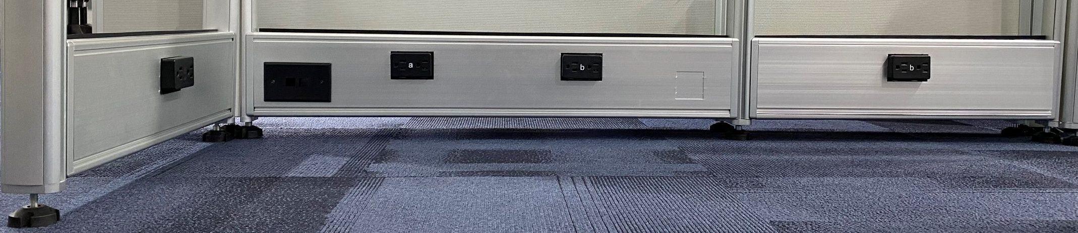
RACEWAY
The raceway is typically the bottom-most “panel” and allows for electric to run into every cubicle requiring power. It typically comes in 3 sizes: 600mm*150mm, 900mm*150mm, 1200mm*150mm. Also 1000mm*150mm when a door is used.
Inside each raceway is either a power module that’s been mounted to the raceway, or a pass-through jumper that passes the electric from one power module to the next. A raceway is not used if neither a pass-through jumper runs through it, or there is no power module.
Receptacles - aka outlets or duplexes - clip into power modules and through cut out holes in kickplates.
Raceways can also run above the work surface - called beltway power - but this is very uncommon since it means all the wires and cords would be out in the open.

L
SPECIFICATIONS
RECEPTACLES / POWER OUTLETS
There are 4 lettered designations of standard receptacles: A, B, C, D. Although there are slight differences in how each is wired internally, the letters are primarily reference points for the electrician to help him/her keep track of how to combine various receptacles of the same letter into one group of connections that all lead to their dedicated 15 amp breaker.
While each receptacle can draw up to 15 amps, typically each cubicle will draw 3-5 amps at any given point in the day - distributed into however many receptacles are being used and how users plug in their electronics ( i.e.computer in one receptacle, all other accessories in another).
Electricians should wire matching letters together to reach the breaker’s 15 amp capacity (allowing up to 2.5 amps for each receptacle). If any one group of lettered receptacles (i.e. - all the A’s) combines for more than 15 amps, then another infeed must be used.
Breaking it down further, if each letter uses 2.5 amps on average, then any one cluster can use up to 6 of that lettered receptacle (6 receptacles * 2.5 amps = 15amps). Which means, by evenly dispersing all 4 letters, the receptacles should be able to support up to a 12-pack of cubicles on one infeed plus 4 breakers.
Common Equipment Amperages:
•Personal Computer - 2.00 - 4.00
•Computer Monitor - .25 - .50
•Laser Printer - 4.50
•Desktop Plotter - 1.50
•Desk Fan - .50 - 1.00
•Desk Heater - 8.50 - 12.50
(Not recommended to use in cubicle)
•Task light - 1.00
•Fan - 1.00
•Paper Shredder - 4.00 - 12.00

SPECIFICATIONS

1000W RACEWAY
1200W RACEWAY
WORKSTATION
ACCESSORIES
IN-STOCK / ACCESSORY FINISHES


2-Drawer Lateral File


White Walnut GreyFog StormGrey
Wardrobe Cabinet
SIT-STAND DESK BASE UNIVERSAL
PRODUCT DIMENSIONS*
WIDTH
40in - 72in
DEPTH
22in
HEIGHT
24in - 49in
*dimensions are for base only and do not include the surface
IN-STOCK / SURFACE FINISHES
*in-stock base color is white
White Walnut GreyFog StormGrey
IN-STOCK / ACCESSORY FINISHES
LATERAL FILE
TWO-DRAWER
PRODUCT DIMENSIONS
White Walnut GreyFog StormGrey
BOX-BOX-FILE STORAGE
IN-STOCK / ACCESSORY FINISHES
PRODUCT DIMENSIONS
White Walnut GreyFog StormGrey
DUAL MONITOR ARMS
PRODUCT DIMENSIONS
WARDROBE CABINET UNIVERSAL
IN-STOCK / ACCESSORY FINISHES
PRODUCT DIMENSIONS
White
Walnut GreyFog StormGrey
STORAGE CABINET
IN-STOCK / ACCESSORY FINISHES
PRODUCT DIMENSIONS
White Walnut GreyFog StormGrey
IN-STOCK / ACCESSORY FINISHES
PRODUCT DIMENSIONS
White Walnut GreyFog StormGrey
ACCESSORIES


Frosted Sliding Door
Swinging Door Shown above :
8'x8' 82" with Grey base and Charcoal accent panel with swinging door accessory
WHITEBOARD
PRODUCT DIMENSIONS
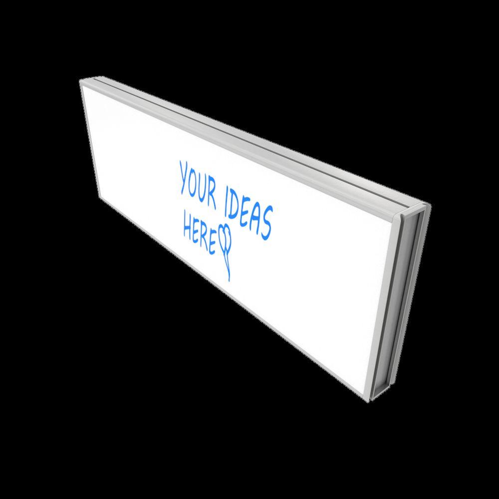
AGNETIC WHITEBOARD
PRODUCT DIMENSIONS

SHELF
IN-STOCK / ACCESSORY FINISHES
PRODUCT DIMENSIONS

White Walnut GreyFog StormGrey
GLASS DOOR
PRODUCT DIMENSIONS
ENVIRONMENT IMAGES


ENVIRONMENT IMAGES


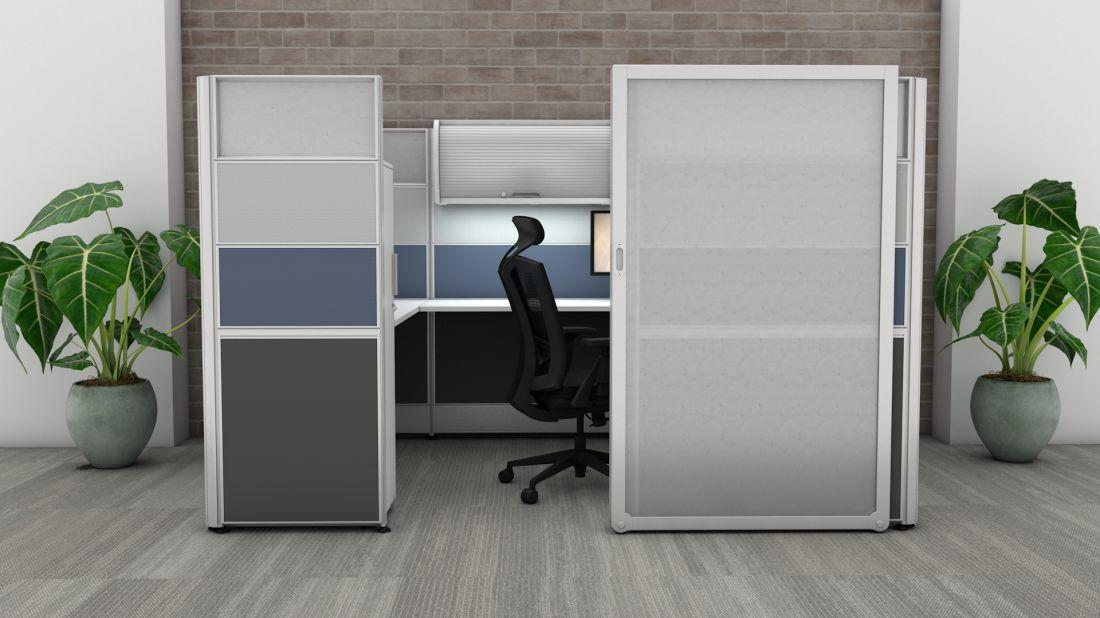
ENVIRONMENT IMAGES


FREQUENTLY ASKED QUESTIONS
FREQUENTLY ASKED QUESTIONS
Q: What is the grommet situation like? In some views, it appears there is a corner grommet only.
A: We have surfaces with and without grommets. Surfaces with grommets typically come with one corner grommet and all our corner worksurfaces have one grommet in the far back corner.
Q: Does the Sunline Signature system have belt line power?
A: Yes, Sunline Signature has the ability to run power in other locations in additional to the raceway. This can be done either integrated in the panel system or by a desk top mounted power device.
Q: Is all electrical UL listed?
A: Yes, our electrical components are UL listed.
Q. What storage options do you have to offer and what material are they made of?
A. All of our storage options are low pressure laminate. We have :
Frosted sliding glass door
Swinging door
Standing desk base
Full height box/box/�le
Full height �le/�le
Mobile box/�le with seat cushion
Q: Do you have the ability to key alike?
2-drawer lateral �le
Wardrobe cabinet
Storage tower
Low credenza side storage
Overhead storage cabinet
Overhead tasklight
A: Yes, keyed and alike, with master key available - full key program.
Hanging shelf
Transaction top
LM dual monitor arm
Desktop sit-stand
Double whiteboard
Single magnetic whiteboard
ION
CERTIFICATIONS
The Sunline Signature system meets the following standards:
ISO9000/9001


*Certi�cates available upon request
GreenGuard Environmental Compliance Agency

International Occupational Safety and Health Administration
