
Isuzu Npr Nqr 2000 Electrical Troubeshooting Full download: http://manualplace.com/download/isuzu-npr-nqr-2000-electrical-troubeshooting/ This is the cut pages sample. Download all 255 page(s) at: ManualPlace.com
Hazardlights................110-6 Headlights...................100 Heater.......................60 Horns ....................... 40 Ignitionsystem .................. Indicators .................... 80 Licenselight ................ 110-1 Lightingswitchdetails. .......... 12 ....... 12-3 Powerdistribution .............. 10 ....... 10-4 Soundsystem................150 ....... 150 Speedometer ................. 33 ....... 33-1 Startingsystem................ 21 ....... 21-2 Taillights...................110-1......110-3 Turnlights. ................ .110-6 ..... .110-8 Vehiclespeedsensor(VSS)......33 ....... 33-1 Windshieldwiper/washer
........ 91 ........ 91
Gas 60-1 63-2 44-4 89-1 39-4 .112-1 60-1 ,110-13 ...71-2 22-2 155 63-2 ..117-2 .110-18 .117-2 .. 114 ... 24 81-2 .110-2 ..81-2 ..11-4 -.81-2 .14-4 .110-8 .100-2 .60-1 ...40 ...20 80-3 Allinformationcontainedinthismanualisbasedonthelatestproductinformationavailableatthatimeofprinting.Wereservetherighttomakechangesatanytimewithoutnotice.Nopartof thispubticationmaybereproduced,storedina retrievalsystem,ortransmitted,inanyformbyanymeans,electronic,mechanical,photocopying,recording,orotherwise,withoutpriorwritten permissionofthepublisher.Thisincludestext,figuresandtables. ©1999AMERICANISUZUMOTORSINC. PrintedinU.S.A.

2000 NPR/NQR
ElectricalTroubleshootingManual Contents HowtoUseThisManual ........... Troubleshooting .................. Fuse/RelayInformation ............ CircuitSchematics(seeCircuitIndex) ComponentLocationPhotographs ... HarnessConnectorViews.......... ConnectorandWireHarnessRouting.
CircuitIndex Diesel ... 2 Airconditioner 2-10 Blowercontrols .............. 60 ... 6 Compressorcontrols..........63 Anti-lockbrakesystem(ABS).....44 201 A/Tshiftindicator .............. 89 202 Automatictransmissioncontrols ... 39 203 Backuplights ................ 112 Blowercontrols................60 Brakelights................110-12 Brakewarningsystem........... 71 Ceramicheater................ 61 Chargingsystem...............22 Cigarettelighter. .............. 155 Compressorcontrols............63 Consolelights................ 117 Corneringlights. ............ 110-16 Dashlights .................. 117 Domelight................... 114 Enginecontrols................23 Enginecoolanttemperaturegauge .. 81 Enginestopsystem. ............ 26 Exhaustbrakesystem...........25 Frontparklights .............. 110 Fuelgauge ................... 81 Fuseboxdetails ............... 11 Gauges......................81 Grounddistribution ............. 14
HOWTOUSETHISMANUAL
TroubleshootingInformation
Thismanualcontainsthefollowingtroubleshooting information:

• FuseInformation
• CircuitDetails
ElectricalCircuitSchematic
ComponentLocationIndex CircuitOperation
QuickChecks(ifrequired)
Troubleshooting(ifrequired)
• ComponentLocationPhotographs
• HarnessConnectorFaces
• Harness
RoutingViews
TheElectricalCircuitSchematicshouldalwaysbe yourstartingpointinusingthisElectricalTroubleshoot¬ ingManual.Theschematicshowstheelectricalcurrent pathswhena circuitisoperatingproperly.Itisessential tounderstandhowacircuitsrtou/dworkbeforetryingto figureoutwhyitdoesn't.Schematicsareshownwith thestarterswitchintheOFFpositionandother switchesintheoffor"atrest"position.
TheComponentLocationIndexhelpsyoufindwhere thepartsofa circuitarelocatedina vehicle.Abrief statementofthelocationisgivenandalsoa reference to a photographthatshowsthecomponent.These ComponentLocationPhotographsareinsection201. Theindexalsoliststhenumberofcavitieswithineach connectorandtheconnectorcolor.Notallcavitieswill havewires.
TheCircuitOperationwillhelpyoutounderstandthe circuit.Itdescribesthecomponentsandhowthecircuit works.
PageNumbering
Thismanualisorganizedintosectionswithmostsec¬ tionscontainingcircuitdetails.Eachsectionhasa uniquenumberthatwillnormallyremainthesame, yearafteryear.Forexample,theheadlightscircuitwill besection100withthefirstpageofthesectionnum¬ bered100.Thefollowingpagesofthissectionwillbe numbered100-1,100-2,and100-3.
2

Symbols Entire component shown Normallyopen switch (— 1 Onlypartofcomponent shown;remainder shownelsewhere Multi-positionswitch Componentname Gangedswitch contacts Dashedlineshows mechanicalconnection Fuse x/s x^s ~^—I Relay,shownwithnocurrentthrough relaycoil;whencurrentflowsthrough coil,contactarmchangesposition YVxv HOTATALLTIMES mF.5^ D ECU(BAT) |LJ10* •^.^ 01iuw&vunctyy16^[Cf>eiiL '^withtheignitioninRUN '~~~~~~~—Identification ^~^^^Currentrating ^7 \ Coil Circuit Breaker Solenoid Fusiblelinkconnectedtoscrew terminal(shownseparated) Fusible Link Solenoid Valve Horn I~ T ^^™ """ BRAKE Brake ndicator Indicatorlight; 1illuminatesa |symbolorword(s) Speaker (cont'd) 2-1

HOWTOUSETHISMANUAL
Resistor Variable resistor
.....
.......
........
.......
Potentiometer
Capacitor
TK—r Motor Brush
positive currentflows
arrow
2-2
Symbols(cont'd)
BLK...... BLU...... BRN .....CLR ..... GRN..... GRY ..... LTBLU ... LTGRN... ORN .....PNK .....RED
VIO...... WHT..... YEL......
black ........ blue ...... brown ....... clear .......green ........gray .... lightblue .. .lightgreen ......orange
pink ........ red ....... violet
white ...... yellow Wireand connectorcolors
Wavylinemeansthewireis -5 brokenbythebindingofthebook butcontinuesonthenextpage
Arrowmeanswireconnectsto anothercircuit;showsdirection ofcurrentflow
Circuitiscontinuedwhereindicated; arrowshowsdirectionofcurrentflow andisrepeatedwherecircuitcontinues Diode;
in
direction
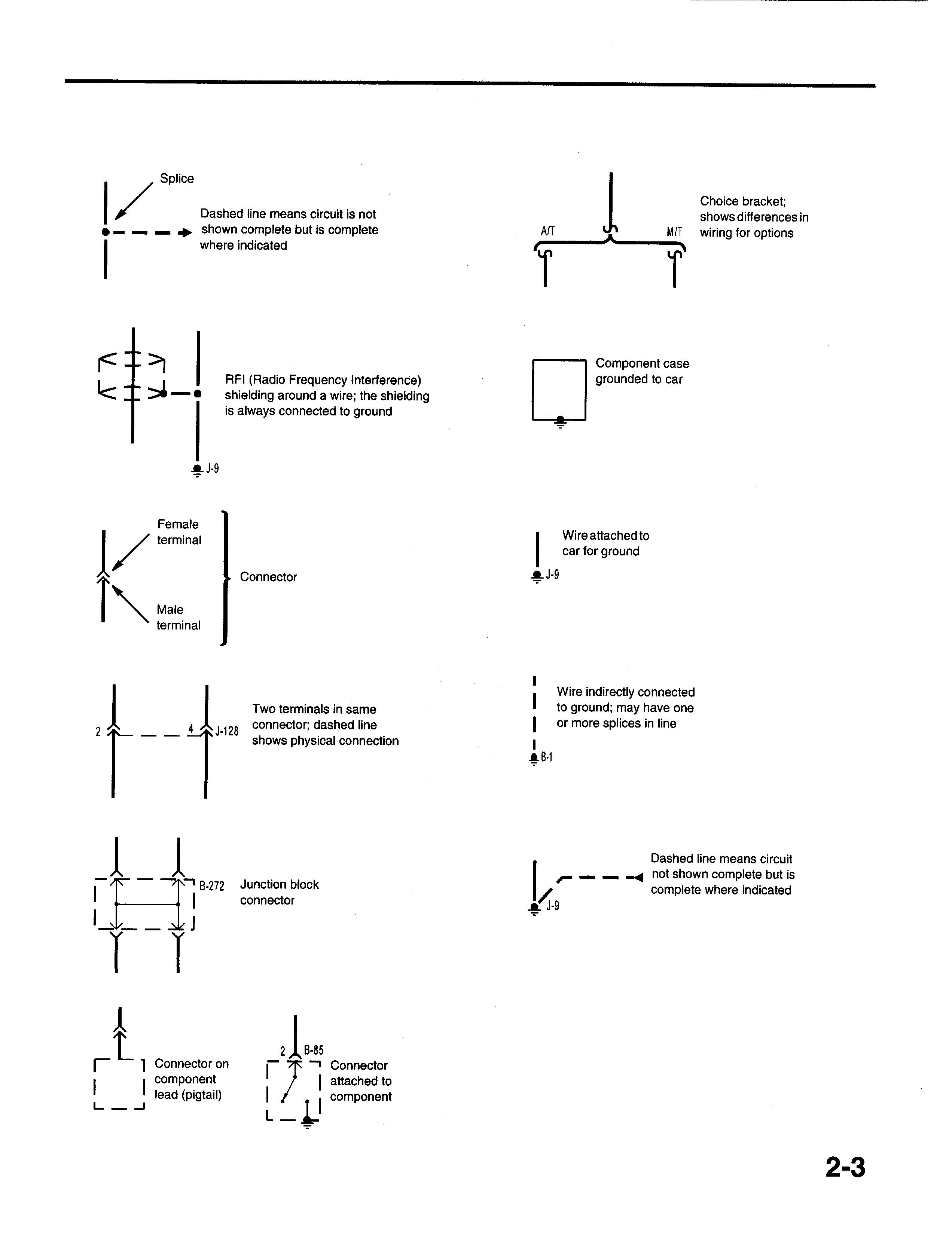
Dashedlinemeanscircuitisnot showncompletebutiscomplete whereindicated A/T T M;T T Choicebracket; showsdifferencesin wiringforoptions r^^ i<±^Componentcase groundedtocar RFI(RadioFrequencyInterference) shieldingaroundawire;theshielding isalwaysconnectedtoground -J-9 Female terminal Male terminal Wireattachedto carforground Connector -J-9 4jfcj-128 Twoterminalsinsame connector;dashedline showsphysicalconnection Wireindirectlyconnected I toground;mayhaveone | ormoresplicesinline AB-1 B-272 Junctionblock connector Dashedlinemeanscircuit notshowncompletebutis completewhereindicated K» i r i Connectoron component lead(pigtail) 21B-85 ,1 a Connector attachedto component
Splice
CircuitSchematics

Circuitschematicsbreaktheentireelectricalsystem intoindividualcircuits.Electricalcomponentsthat worktogetherareshowntogether.
Eachdrawingisarrangedsothatcurrentflows frompositiveatthetopofthepage,toground,at thebottomofthepage.The"hot"labelsatthetopof a fuseshowwhenthestarterswitchsuppliespowerto thatfuse.
Wiresthatconnecttoanothercircuitareshownwithan arrowheadpointinginthedirectionofcurrentflow.The nameofthecircuitthatshareswiringisprovidedforref¬ erence.
"SeeFuseBoxDetails"meansthatthereareothercon¬ nectionstocircuitsthatarenotshown.Theseshared circuitsareshownontheFuseBoxDetailscircuitsche¬ matic."SeeGroundDistribution"meansthatthereare sharedgroundcircuitswhichareshownontheGround Distributioncircuitschematic.
Noattemptismadeontheschematictorepresent componentsandwiringastheyphysicallyappearon thecar.Forexample, a 4-footlengthofwireisnot treatedanydifferentlyina schematicthanonewhichis onlya fewincheslong.Thenumberofcavitiesforeach connectorislistedintheComponentLocationIndex ratherthanbeingillustrated.Similarly,switchesand othercomponentsareshownassimplyaspossible withregardtofunctiononly.
Theexampleonthispageshowsa hornsschematic. LocatethehornschematicbyusingtheCircuitIndex. Thecircuitschematicwilllooksimilartotheoneshown below.Theschematicisreadfromtoptobottom.
Voltageisappliedtothehornrelayatalltimes.When therelaycoilisgroundedbyclosingthehornswitch, therelaycontactsclose.Whentherelaycontactsare closed,boththeLHandRHhornsareenergized.
HOWTOUSETHISMANUAL
GR 1—— 1 GRN/RED 3^ GRN/RED BLKJ ^ N J 4\ L -lA8-24 s ^~ ?B-70 1 GRN ———————————————————————————-^ 'Q.^ Horn Switch f HOTATALLTIMES LI BRN GRNWHT 3? GRNfWHT Steering Wheel GRN/WHT I/ L-! r F-18 HAZARD,HOR 20A G CRN Horn / Relay / ;H-5 L ^ 8-1 |Fuse ,Box N1 RN| SeeFuse BoxDetails Page11-1(Diesel Page11-5(Gas) -ICab |Relay ' Box GRNfW Right Hand Horn '1 iA 1A I -5 ^\ Left \ Hand -—~-\ Horn 2-4
PowerDistribution
ThePowerDistributionschematicshowsthewiring fromthebatteryandgeneratortothestartersolenoid, relaybox,fusebox,starterswitchandlightswitch.The firstcomponentafterafusiblelinkisalsoshown.Incer¬ taininstances,thefirstcomponentaftera fuseboxfuse andlightswitchisalsoshown.
ThePowerDistributionschematicreferstoFuseBox DetailsandLightingSwitchDetailsschematics.By usingthesethree(3)schematics,powerdistribution wiringcanbefollowedfromthebatteryandgenerator tothefirstcomponentaftera fusiblelink,fuse,andlight switch.Theabilitytofollowthepowerdistributionwiring tothefirstcomponentineachcircuitisextremelyhelp¬ fulinlocatingshortcircuitswhichcausefusiblelinks andfusestoopen.
Thefusesintheschematicbeloware"HotAtAll Times,"sincebatteryvoltageisalwaysappliedtothem.

BL B K/RE K/Y V 0 1" BLK J^~LL Al —^ J^ AJ ( (VHT 1 f\r~ Heater-A/C HeadlightRelay Exhau Relay Page100and110-10 Brake Page60 Pages and63 and25 NP "~ 1 -998 Jt.P-5 Frame) (Engi B-21 -1 1 ^ —— —— TWh WHT | Wh 21 f1B-20 ) ^\ /\/" i ' L 3 Batteries 4 BLKl BLU •• '^jT6 1 ^^ D C 1——^=0-^ 1 i 1 L- —— -1 ne) \ T | ~* WHT T | Starter Solenoid WHT B-38 -; -J st Relay 21,25 -4 | ^1 - 1Relay 1 fK10^ I8'" 1 / MAIN I"" W10-2 | | J 80A |Starter 1 | * | Page21 WHT| | WHT 1 Q2-2 WHT 1- ——-1 Generator 2^ Page21 WHT Uab Relay I | I i | DUX Box ' rti^8 m^7 itr-6 fti" i i bSTOP jTA'1- jDOME jEcu•BAT) i 1 LlJLIGHT LLJLIGHT LlJLIGHT LtJIOA I | 10A IOA 10A | SeeFuse SeeFuse SeeFuse SeeFuse BoxDetails, BoxDetails, BoxDetails, BoxDetails, Page11 Page11 Page11 Page11 (cont'd) SH-6 WHT ———————————————————§ Fuse 2-5
CircuitSchematics(cont'd)

FuseBoxDetails
FuseBox
schematicshowsallofthewiring betweena fuseandthecomponentsconnectedtothat fuse.TheFuseBoxDetailsschematicishelpfulin locatinga shortcircuitthatcausesa fusetoopen.This schematicmayaidintroubleshootinganinoperative circuitbyshowinga secondcircuitthatusesthesame fuse.Ifthesecondcircuitworks,thenthefuseandcer¬ tainwiresoftheinoperativecircuitaregood.
HOWTOUSETHISMANUAL
WHT/GRN WHT/GRN | WHT/GRN | WHT/GRN | WHT/GRN | WHT/GRN 261 251 241B-109121 13 ^ ^N —^ ^S—, | 1 ElectronicBrakeControlModule(EBCM) Page44 1 Page40 1 Module Page23-4 Page23-4 WHT/GRN HOTATALLTIMES !JHF-19 -) ABS(BAT J25A TtL/KtU 5^B-30 I— 1 l j Hazard Warning mF.i3 n-|F-i8 ) h TURN, ^HAZARD LJSfLIGHT LJHORN 10A \20A 1 HOTINONANDSTART | Switch Page1 B-110 ] 1 | 10-7 GRN | ISJ^B-79 DataLink Connector Pages23 and39 HOTATALLTIMES GRN GRN | GRN [~Ll 1 1— | 1 1 L ' Horn | Engine TH'II'O 1 Relay Control K'l'Y \ GRN | lj^B-30 r~i l l i i Hazard Warning Switch Page110-7 -| -iCab J^-24|Relay —1 i Box | 1 J HOTINONANDSTART | -1 Fuse fTr-14 iBox •) ECU(IGN) LJ10A | J BLK/YEL BLK/YEL | BLK/YEL | 6^8-234 ijf8-261 r i i~ i 1 l I l i- -i (ECM1 2-6
The
Details
LightingSwitchDetails
LightingSwitchDetailsschematicshowsallthe wiringbetweenthelightswitch,lightrelays,andthe componentsconnectedtotheoutputofthelightswitch andrelays.TheLightingSwitchDetailsschematicis helpfulinlocatinga shortcircuitontheoutputsideof thelightswitchandrelays.

The
G GR GR 1—— 11 | | Headlights L RN/BLK ^ -"I N/ORN ^ N/ORN ,Lig ^ ISw Off ^^Head 1 [park | '——4- -* BLK\ 1 ' | 1 [!-1. GRNfBLK | L .JIB'22 r' ^ laillight ;B-70 SeeGround llstribution Page14 .-^ B-7 GRN LTGR Combination hting 1Switch tch | LTGR HOTATALLTIMES 'BLK| ]|YB-22 N/RED N/RED 1 r 1 i Illumin Contr Page -,F F-7 |B TAILLIGHT 10A 1 GRN/BLK LTGRN/RE GRN/WIr B-160 [ ~] | L - -i C ation | Her A 17 p use ox See Box Ca Rel Box D ^ T ^ eftF omb ght ssem age Fuse Details ay LTGRN/R ;B-5 -1 ^ ont nation biy 10-1 ED 10 r i Radio Page -T--^-^ LTGRNf 1 RED 1 ^ LTGRNf RED ' 1? ] RED r B-28 I 1 l \-l 0/DO 1 SWIT - -• ' Page 1 andl 5" - -A/T;H-1 SN-) 1 l FF CH 39-2 7 2 ' 1 1 (cont'd) 2-7
CircuitSchematics(cont'd)

GroundDistribution
TheGroundDistributionschematicsshowwhichcom¬ ponentssharea groundpoint.Thisinformationcan oftenbea time-saverwhentroubleshootinggroundcir¬ cuits.Forexample,intheschematicbelow,ifboth headlightsandthepark/turnlightononesideareall out,youcouldsuspectanopenintheircommon groundwireorthegroundconnectionitself.Onthe otherhand,ifoneofthelightsworks,youknowthatthe groundandthewireuptothesplicearegood.You havelearnedthisjustbyinspectingtheschematicand knowingthevehicle'ssymptoms.Noactualworkonthe lightingsystemisneeded.
HOWTOUSETHISMANUAL
LeftTailLightAssembly RightTailLightAssembly L'(;e"se PagesHO-1,110-7,110-12and110-17 Pages110-1,110-7,110-12and110-17 rlate r '"' r -1 Light Tail Stop Turn Back-up Tail Stop Turn Back-up i^i :©®®! ©(8)®l Cx-l V V V 1 V V V 1 \W\ i T T T I i T T T l -F 1^R-2 Engine ABS Stop Hydro Motor Unit Page26 Page44-2 r- ~i r- -i 11 11 1J LJ 1"'J-34 IS^'J^A AJ-9 Aj-999 16^J-79 8S;H-16 / 1 6} - withH.B.B, «M/T;R-1 HRR -' O.I i Condenser Level i Fan Sensor pa^e('3-2 Page71 l '- - -1 r -i i 1 1 1 1 , L. J '-.-J I 2AJ-51A YELfBLU Y 2^J-128 i zAj-51 .» ^ 1 6^ ' | SR-6 Neutrai Switch Page r" 1 RED 1;;E-11 10^H-14 1 1 25-5 -l J r ExhaustBrake MAGValve Pages25-2and25-6 l- -i 1 1 2-1 - c 'J-31 2-8
Acomponentlocationindexfollowseachschematic. Exceptforthelocationofobviouscomponentslikeleft headlight,theindexliststhelocationofeverycompo¬ nent,connectorandgroundintheschematic.The indexalsogivesreferencestocomponentlocationpho¬ tographslocatedinsection201.Thenumberofcavities ineachconnectorandtheconnectorcolorisalso listed.Wiresmaynotbeusedinallconnectorcavities.

Location
Component
ComponentLocationIndex (RefertoSection201forphotographs.) Component PhotoNo. FuseBox.................. Leftsideofdash,behindpanel...................................... 81 LeftHorn.................. Leftsideofenginecompartment,belowheadlight.......................15 RightHorn ................ Rightsideofenginecompartment,belowheadlight......................17 Connector B-2(13-WHT)..............Underleftsideofdash,aboveleftsideofsteeringcolumn ................ 71 H-41(16-GRN).............Underleftsideofdash,atkickpanel ................................. 63 Ground C-39 ..................... Rightrearcornerofenginecompartment..............................42 2-9
HOWTOUSETHISMANUAL
Five-StepTroubleshooting

Thefollowingfive-steptroubleshootingprocedureis recommended:
1. VerifytheProblem
Checktheproblemcircuit'soperationtobesureyou understandwhat'swrong.Donotbegindisassemblyor testinguntilyouhavenarroweddownthepossible causes.
Ifthesystemyouaretroubleshootinghasa built-inselfdiagnosticsystem,refertotheappropriatesectionof theServiceManual.
2. AnalyzetheCircuitSchematic
Analyzetheschematic.ReadtheCircuitOperationtext ifyoudonotunderstandhowthecircuitshouldwork. Checkcircuitsthatsharethewiringwiththeproblem circuit.Thenamesofcircuitsthatsharethesamefuse, ground,switch,etc.,areincludedoneachelectrical schematic.SharedcircuitsarealsoshownonPower Distribution,GroundDistribution,DashFuseBox,and LightingSwitchDetailspages.Trytooperatethe sharedcircuits.Ifthesecircuitswork,thentheshared wiringisOK.Thecausemustbewithinthewiringused onlybytheproblemcircuit.Ifseveralcircuitsfailatthe sametime,chancesarethepower(fuse)orgroundcir¬ cuitisfaulty.
3. FindtheCause
• narrowdownthepossiblecauses
• usethetroubleshootinghints
• makethenecessarymeasurementsasgivenin thetroubleshootingprocedures
• beforeyoureplacea component,checkpower, signal,andgroundwiresatthecomponenthar¬ nessconnector
4. RepairtheProblem
Oncethespecificproblemisidentified,maketherepair. Besuretousepropertoolsandalwaysobservesafe procedures.
5. ChecktheRepair
Checktherepairedcircuit'soperationinallmodesto makesurethatyou'vefixedtheentireproblem.Ifthe problemwasa blownfuse,testallcircuitsonthatfuse. Makesurethatnonewproblemsturnup.
TestEquipment
VoltmeterandTestLight
Usea voltmeterortestlighttocheckforvoltage.While a testlightshowswhetherornotvoltageispresent, a voltmeterindicateshowmuchvoltagethereis.
CAUTION:Anumberofcircuitsincludesolidstate devices.Voltagesinthesecircuitsshouldbetested onlywith a 10-megaohmorhigherimpedance digitalmultimeter.Neverusea testlightoncircuits thatcontainsolid-statedevices.Damagetothe devicemayresult.
Oncircuitswithoutsolid-statedevices,a testlightmay beusedtocheckforvoltage.Atestlightismadeupof a 12-voltbulbwith a pairofleadsattached.After groundingonelead,touchtheotherleadtovarious pointsalongthecircuitwherevoltageshouldbe present.Thebulbwillgoonifthevoltageatthepoint beingtestedisgreaterthan5volts.
Self-PoweredTestLightandOhmmeter
Usea self-poweredtestlightorohmmetertocheckfor continuity.Theohmmetershowshowmuchresistance thereisbetweentwopointsalonga circuit.Lowresis¬ tancemeansgoodcontinuity.
CAUTION:Neverusea self-poweredtestlighton circuitsthatcontainsolid-statedevices.Damageto thesedevicesmayresult.
Diodesandsolid-statedevicesina circuitcanmakean ohmmetergivea falsereading.Tofindoutifa compo¬ nentisaffecting a measurement,takeonereading, reversetheleads,andtakea secondreading.Ifthe readingsdiffer,thecomponentisaffectingthemea¬ surement.
Circuitsthatcontainsolid-statedevicesshouldonlybe testedwitha 10-megaohmorhigherimpedancedigital multimeter.
2-10
Aself-poweredtestlightconsistsofa lightbulb,battery andtwoleads.Iftheleadsaretouchedtogether,the bulbwillgoon.
Self-PoweredTestLight
Aself-poweredtestlightisonlyusedonanun-powered circuit.Firstdisconnectthebatteryorremovethefuse thatfeedsthecircuityouareworkingon.Selecttwo pointsalongthecircuitthroughwhichthereshould havecontinuity.Connectoneleadoftheself-powered testlighttoeachpoint.Ifthereiscontinuity,thetest light'scircuitwillbecompletedandthebulbwillgoon.
FusedJumperWire
Usea jumperwiretobypassanopencircuit.Ajumper wireismadeupofanin-linefuseholderconnectedtoa setoftestleads.Itshouldhave a fiveamperefuse. Neverusea jumperwireacrossanyload.Thisdirect batteryshortwillblowthefuse.
TroubleshootingTests
TestingForVoltage
Thistestmeasuresvoltageina circuit.Whentestingfor voltageata connector,youmaynothavetoseparate thetwohalvesoftheconnector.Instead,probethe connectorfromtheback.Alwayscheckbothsidesof theconnectorbecausedirtandcorrosionbetweenits contactsurfacescancauseelectricalproblems.
1. Connect one lead of test light to known good ground,orifyouareusinga voltmeter,besureyou connectitsnegativeleadtoground.

2. Connecttheotherleadofthetestlightorvoltmeter tothepointyouwanttocheck.
3. Ifthetestlightglows,thereisvoltagepresent.Ifyou areusinga voltmeter,notethevoltagereading.It shouldbewithinonevoltofmeasuredbatteryvolt¬ age.Alossofmorethanonevoltindicatesa problem.
ShortFinder
Shortfindersareavailabletolocateshortstoground. Theshortfindercreatesa pulsingmagneticfieldinthe shortedcircuitandshowsyouthelocationoftheshort throughbodytrimorsheetmetal.Itsuseisexplainedin thefollowingtroubleshootingtests.
RED ON/ / / Switch
-s \ BLU ^—|Voltmeter \ -^ or \ / TestLight \ /\ -T^ |Solenoid 2-11
TroubleshootingTests(cont'd)
TestingForContinuity
Thistestchecksforcontinuitywithinacircuit.Whentest¬ ingforcontinuityata connector,youmaynothaveto separatethetwohalvesoftheconnector.Instead,probe theconnectorfromtheback.Alwayscheckbothsidesof theconnectorbecausedirtandcorrosionbetweencon¬ tactsurfacescancauseelectricalproblems.
1. Disconnectthenegativecablefromthecarbattery.
2. If you are using an ohmmeter, hold the leads togetherandadjusttheohmmetertoreadzero ohms.

3. Connectoneleadofself-poweredtestlightorohm¬ metertooneendofthepartofthecircuityouwish totest.
4. Connecttheotherleadtotheotherend.
5. Iftheself-poweredtestlightglows,thereiscontinu¬ ity.Ifyou'reusinganohmmeter,lowornoresis¬ tancemeansgoodcontinuity.
TestingForVoltageDrop
Thistestchecksforvoltagedropalong a wire,or througha connectionorswitch.
1. Connectthepositiveleadofa voltmetertotheend ofthewire(ortothesideoftheconnectororswitch) closesttothebattery.
2. Connectthenegativeleadtotheotherendofthe wire(ortheothersideoftheconnectororswitch).
3. Operatethecircuit.
4. Thevoltmeterwill showthedifference involtage betweenthetwopoints.Adifference,ordropof morethan0.5voltsmayindicatea problem.Check thecircuitforlooseordirtyconnections.
HOWTOUSE
THISMANUAL
2-12
TestingForAShortToGroundWithATestLightOr Voltmeter
1. Removetheblownfuseanddisconnecttheload.
2. Connecta testlightorvoltmeteracrossthefuseter¬ minals.Makesurevoltageisbeingappliedtothe batterysidefuseterminal.Checkschematictosee iftheignitionswitchneedstobeinRUN.
3. Beginningnearthefusebox,wiggletheharness. Continuethisatconvenientpointsaboutsixinches apartwhilewatchingthetestlightorvoltmeter.
4. Whenthetestlightblinksorthevoltmeterneedle moves,thereisa shorttogroundinthewiringnear thatpoint.

TestingForA ShortToGroundWithA SelfPoweredTestLightOrOhmmeter
1. Removetheblownfuseanddisconnectthebattery andload.
2. Connectonelead of a self-poweredtestlightor ohmmetertothefuseterminalloadside.
3. Connecttheotherleadtoa knowngoodground.
4. Beginningnearthefusebox,wiggletheharness. Continuethisatconvenientpointsaboutsixinches apartwhilewatchingthetestlightorohmmeter.
5. Iftheself-poweredtestlightblinksortheohmmeter needlemoves,thereisa shorttogroundinthewir¬ ingnearthatpoint.
2-13
SHORTTO ~A\ GROUND LOAD DISCONNECTED
TroubleshootingTests(cont'd)
TestingForAShortToGroundWithAShortFinder
1. Withthebatteryconnected,removetheblownfuse.

2. Connecttheshortfinderbetweenthepositivebat¬ teryterminalandtheloadsidefuseterminal.
3. Closeallswitchesinserieswiththewirethatyou aretroubleshooting.
4. Turnontheshortfinder.Thiswillsendpulsesofcur¬ renttotheshortandcreatea pulsingmagneticfield aroundthewiringbetweenthefuseboxandthe short.
5. Beginningatthefusebox,slowlymovetheshort findermeteralongthecircuitwiring.Themeterwill showcurrentpulsesthroughsheetmetalandbody trim.Aslongasthemeterisbetweenthefuseand theshort,theneedlewillmovewitheachcurrent pulse.Onceyoumovethemeterpastthepointof theshort,theneedlewillstopmoving.Check aroundthisareatolocatethecauseoftheshort circuit.
HOWTO
USETHISMANUAL
2-14

ro i 01

FUSE/RELAYINFORMATION RelayBox /TTH 0 |F-21 ||F-22| II I————I D D ^-s^ J-12 1 a J-13 2 J-14 , I, 5 J-15 J-18 J-16 J-19 D DIDDIDD J-17 J-20 Fuse Number 1 2 3 4 5 F-21 F-22 FuseName MAIN KEY ABS(Gas) GLOW(Diesel) ABS(Diesel) C/HEATER(Diesel) CONDENSERFAN(Diesel) Amps 80A 50A 60A 60A 60A 15A CircuitProtected Powerdistribution Powerdistribution ABS(Gas),Enginecontrols(Diesel) ABS Ceramicheater Notused Condenserfan RelayNumber Relay RelayNumber Relay J-12 Starter J-16 Fuelpump(Gas) J-13 Glow-1(Diesel) J-17 Condenser(Diesel) J-14 C/Heater(DieselM/T) J-18 Exhaustbrakecontrol(Diesel) J-15 Warmcut1(Diesel) J-19 Enginewarmcut2(DieselA/T) A/Cenable(Gas) J-20 I.D.lightrelay 6
Isuzu Npr Nqr 2000 Electrical Troubeshooting
Full download: http://manualplace.com/download/isuzu-npr-nqr-2000-electrical-troubeshooting/
FuseName
HEATER
AIRCON
EXHAUSTBRAKE(Diesel)
VCM(IGN)(Gas) D.R.L.(Diesel) ENGINE(IGN)(Gas) ECU(BAT)(Diesel)
A/TSOLENOID(GAS) DOMELIGHT
TAILLIGHT STOPLIGHT HEADLIGHT(RH) HEADLIGHT(LH) WIPER,WASHER GENERATOR
TURNS/LIGHT ECU(IGN)(Diesel)
VCM(ACC)(Gas)
AUDIO,CIGARLIGHTER
POWERSOURCE ENGINESTOP(Diesel)
FUELPUMP(Gas)
HAZARD,HORN ABS(BAT)
STARTER
Amps
25A 10A 10A 10A 10A 10A 10A 10A 20A 20A 20A 20A 10A 10A 20A 20A 10A 10A 20A 25A 10A
Heater
CircuitProtected
CompressorControls
ExhaustBrakeSystem(Diesel)
EngineControls(Gas) Headlights(Diesel)
EngineControls(Gas) EngineControls(Diesel)
AutomaticTransmissionControls(Gas)
InteriorLights,ExteriorLights,SoundSystem(Gas), Speedometer(Gas)
DashLights,ExteriorLights BrakeLights Headlights Headlights
WindshieldWiper/Washer ChargingSystem
TurnLights
EngineControls
CigaretteLighter,EngineControls,SoundSystem EngineControls
EngineStopSystem(Diesel)
EngineControls,Gauges(Gas) EngineControls,Gauges,Horn,HazardLights ABS
StartingSystem

-n 0 -n <o -n oo -n •~l -n 0) •n 01 •n ^ T u -n M T -l71 0 T <0 s 00 •n •'i S u) -n 01 T ^ 71 u -n M -n
FuseBox
Fuse Number F-1 F-2 F-3 F-4 F-5 F-6 F-7 F-8 F-9 F-10 F-11 F-12 F-13 F-14 F-15 F-16 F-17 F-18 F-19 F-20
6-1
This is the cut pages sample. Download all 255 page(s) at: ManualPlace.com
