A R C H I S H A H A R C H I T E C T U R E P O R T F O L I O G E O R G I A I N S T I T U T E O F T E C H N O L O G Y
Archi Shah
ARCHITECT
Master’s in Architecture graduate with 2 years of work experience and 7 years of academics in Architecture. Skilled in designing High Rise residental , Commercial , Instititional and inclusivity projects such as designing accessibile spaces for disabled. Experience in designinig Bridges and museums. With strong skills in design, project management , and team collaboration , seeking challenging opportunities to apply my knowledge and experience in Architecture Industry
Atlanta , GA
+1 4708440299
ashah667@gatech.edu
linkedin.com/in/archishah98/ arch-hive.com/ArchiShah

SKILLS
CAD
Revit
Rhino 3D
Grasshopper
Sketchup
Illustrator
Photoshop
Indesign

Lumion
Vray
Enscape
3ds Max
Bluebeam Revu
Detail- oriented
Client relations
ADA codes & design
Collaboration
Hand Drafting
COMPETITIONS
Westside Connectivity Bridge in Georgia Tech
WORK EXPERIENCE
Atlanta , GA | May 2022 - Present | Part time
• Collaborated with Praxis3 to create construction drawings compliant with local building codes and ADA codes for Centennial Yards, a $5B mixed-use project in Atlanta.
• Facilitated critical institutional projects for Cobb and Clayton County School District clients totaling $1.2M of budget for 3 schools, approved within 2 months of timelines.
• Produced detailed design specifications & 12 color boards within one month period for the Department of Juvelin Justice of Georgia for a Medical school project.
• Collaborated with clients and contractors to efficiently manage submittals , project schedule and change orders for the Adaptive reuse projects.
• Successfully transitioned from an intern to a part-time employee due to exceptional performance and contribution to various projects.
New York City, NY | March 2022 | Full time
• Designed and produced 15+ iterations and layouts of Interior elements illustrating clarity and colour accuracy, for Judy Shaft Honors College USF.
• Collaborated with experienced architects to create photorealistic 2D visualisations of Judy Shaft Honors College USF.
• Demonstrated strong work ethic and impactful contributions during internship, leading to an extension.

Atlanta , GA | Nov 2021 - May 2022 | Part time
• Delivered detailed technical analysis and review of existing buildings of the campus ensuring complete compliance with ADA laws, enhanced accessiblity for disabled to buildings by 35%
• Collaborated with contractors and stakeholders and provided improvement guidelines for new building projects and implemented strategies that increased accessibility.
Ahmedabad, India | Nov 2019 - April 2020 | Full time
• Produced design & technical drawings for high-rise residential and commercial projects.
• Delivered presentations at conferences that resulted in 10 new business relationships
EDUCATION
Atlanta, GA | Aug. 2021 - May 2023
Master’s in Architecture
GPA 3.4/4
Ahmedabad , India | Aug. 2016 - June 2021
Bachelor’s in Architecture
Accessibility for Disabled in Railway Terminals
GPA 7.8/10
RESEARCH PAPER
Georgia Institute of Technology Institute of Architecture , Nirma University
| Architecture Intern Georgia Institute of Technology | Graduate Student Assistant
Architecture Intern
J.W Robinson & Associates | Junior Architect
Morphosis
Apurva Amin Architects |

Sabarmati Rail Terminal Buoyancy Northview Aryan Workspace 3 Valencia Lavish Earth Sope Creek Elementary School Banaras RSP Ahmedabad Pol RSP House of Sports The Terrace House Coorg RSP Corning Museum of Art Passive Infill Building Walkable Neighbourhood Mulberry Fishpond Park Accessibility for Disabled Honors College USF Sin Wave 6 18 26 32 38 46 50 56 58 62 66 78 82 86 88 Centennial Yards
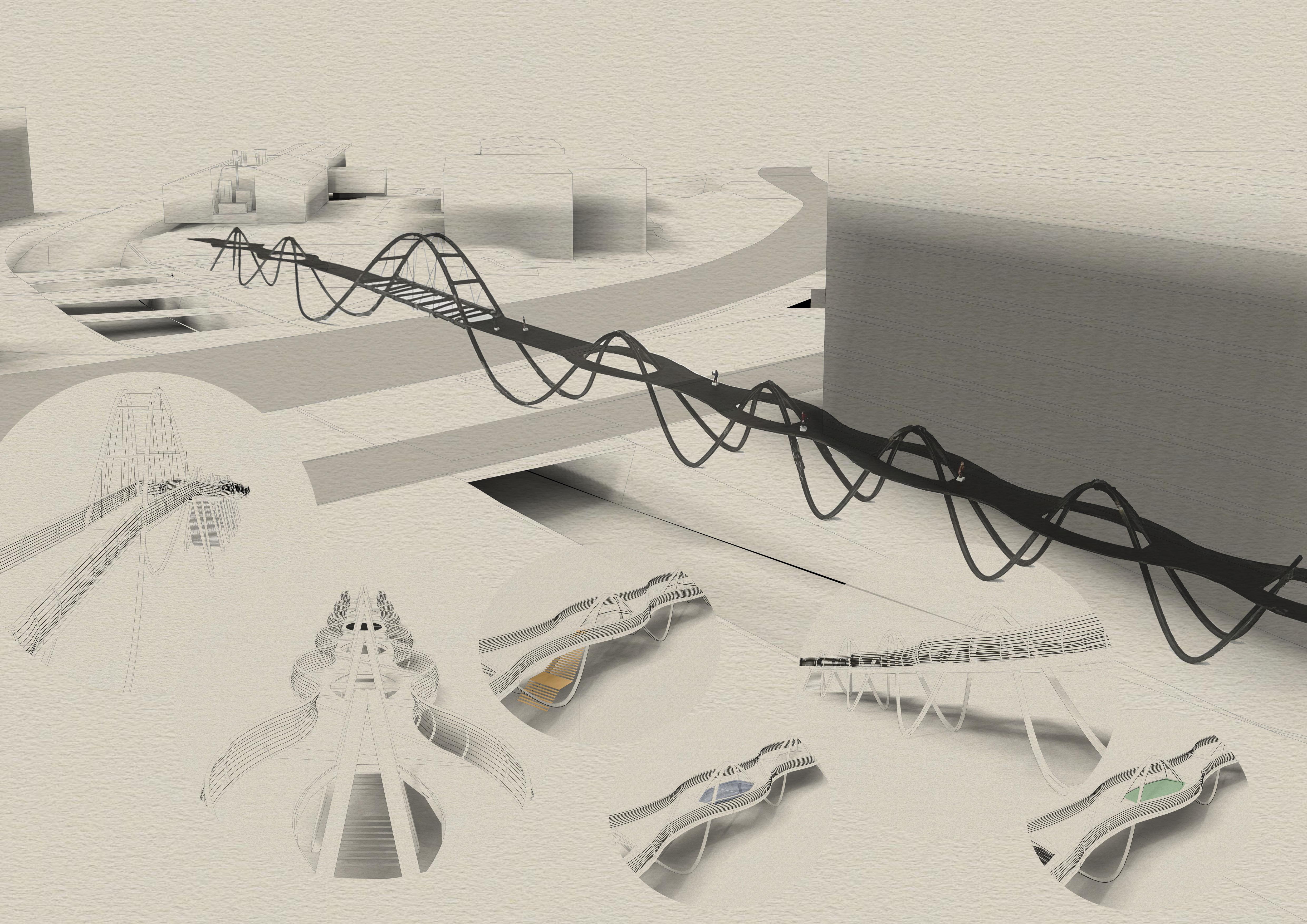
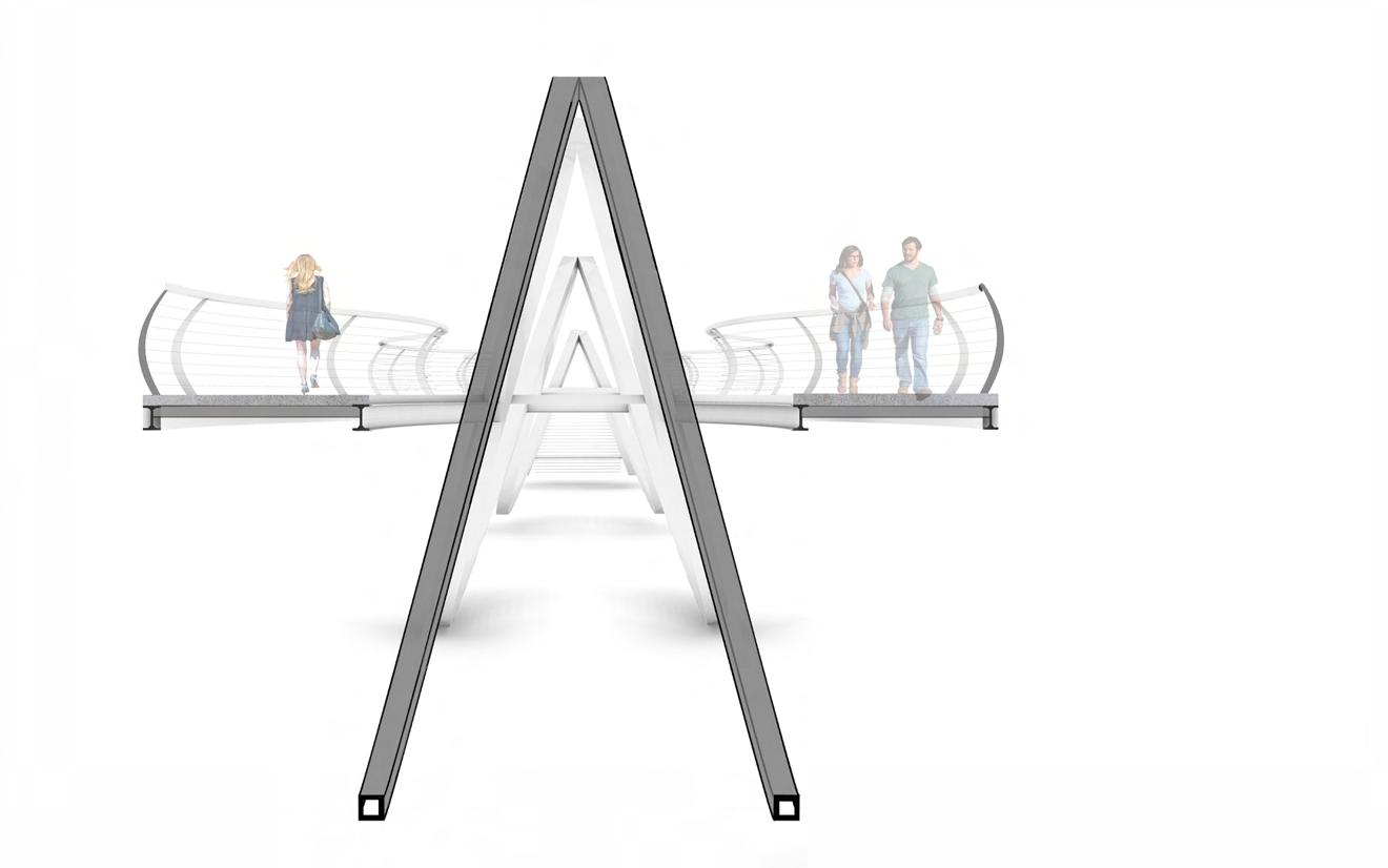
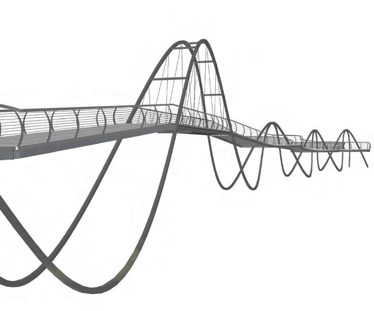
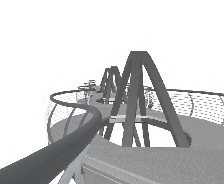
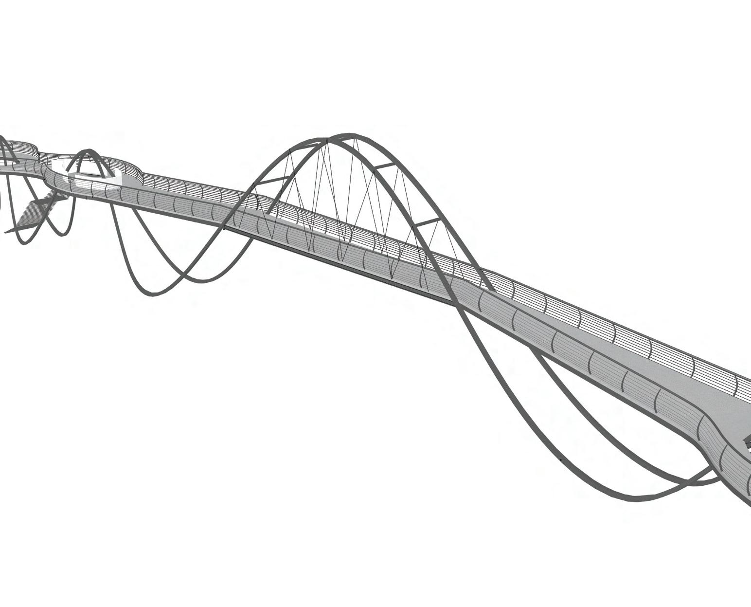
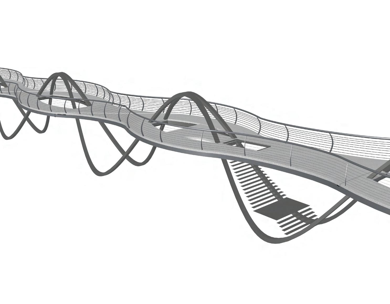
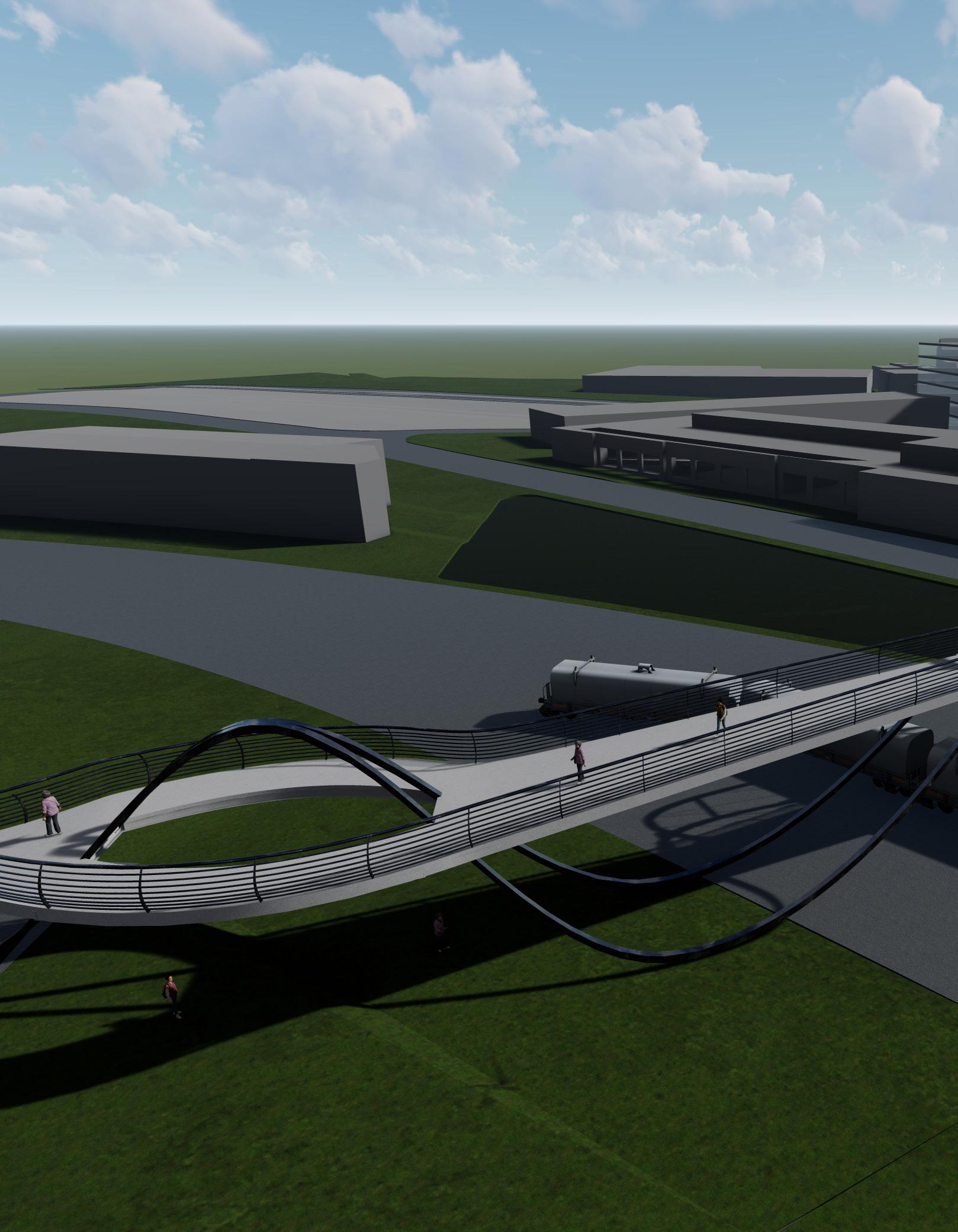
SINE WAV E


WESTSIDE BRIDGE CONNECTIVITY
COLLEGE
Georgia Institute of Technology
LOCATION

Georgia Institute of Technology , Atlanta, GA
MODULE
Graduate Advance studio 2

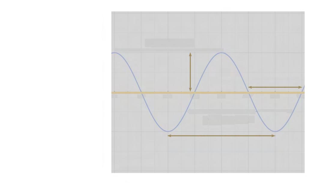
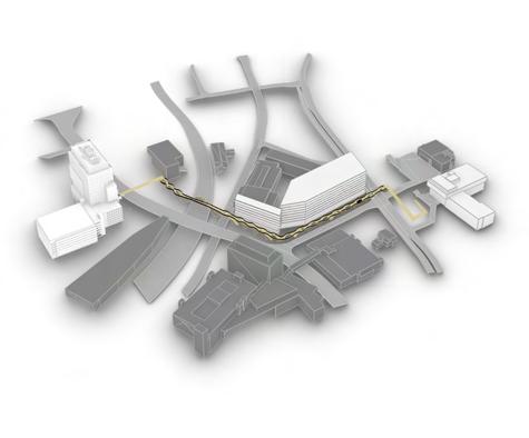
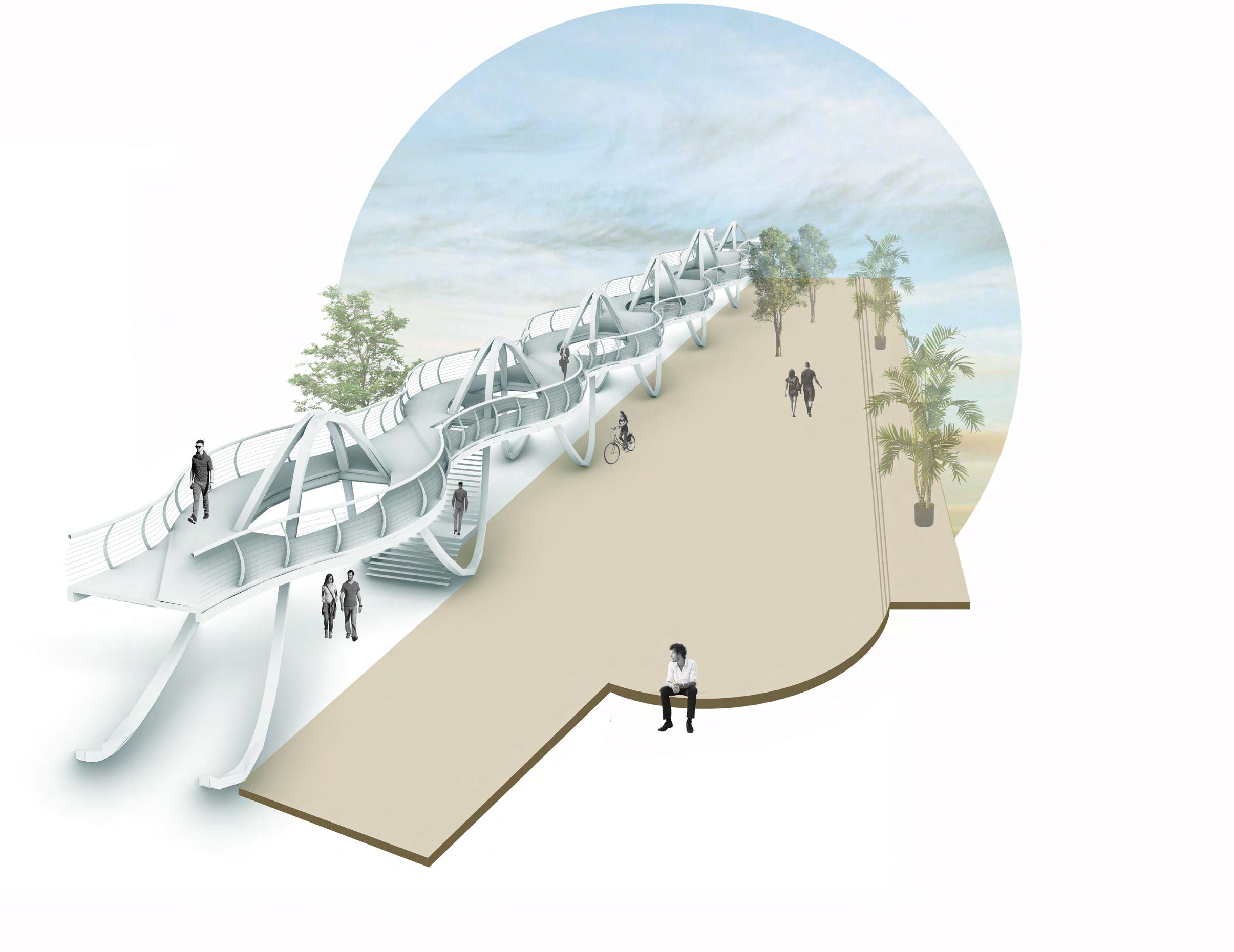
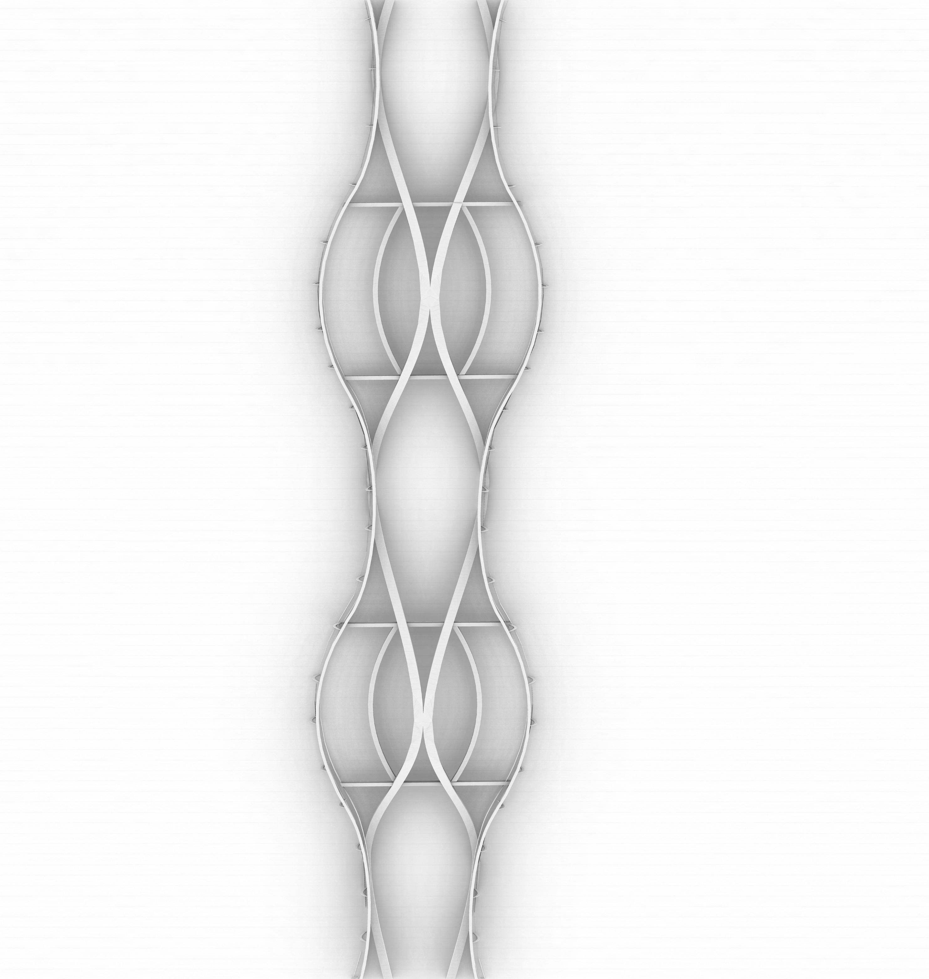
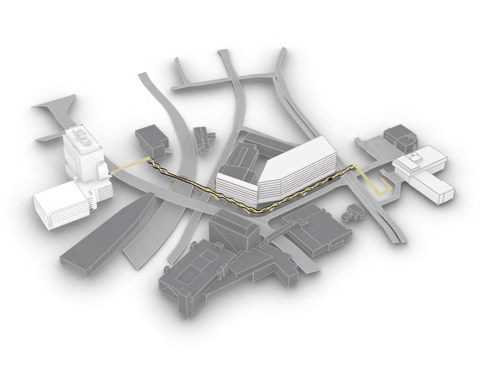
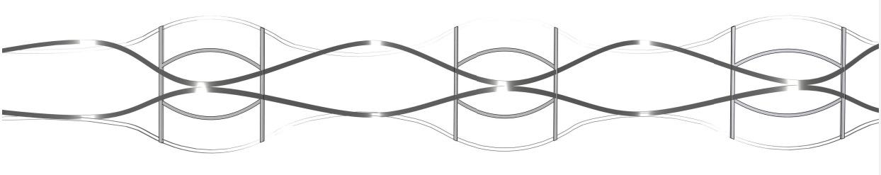
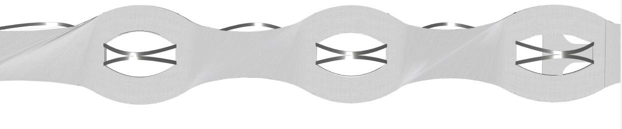
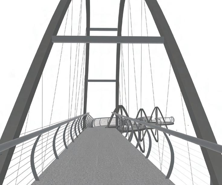
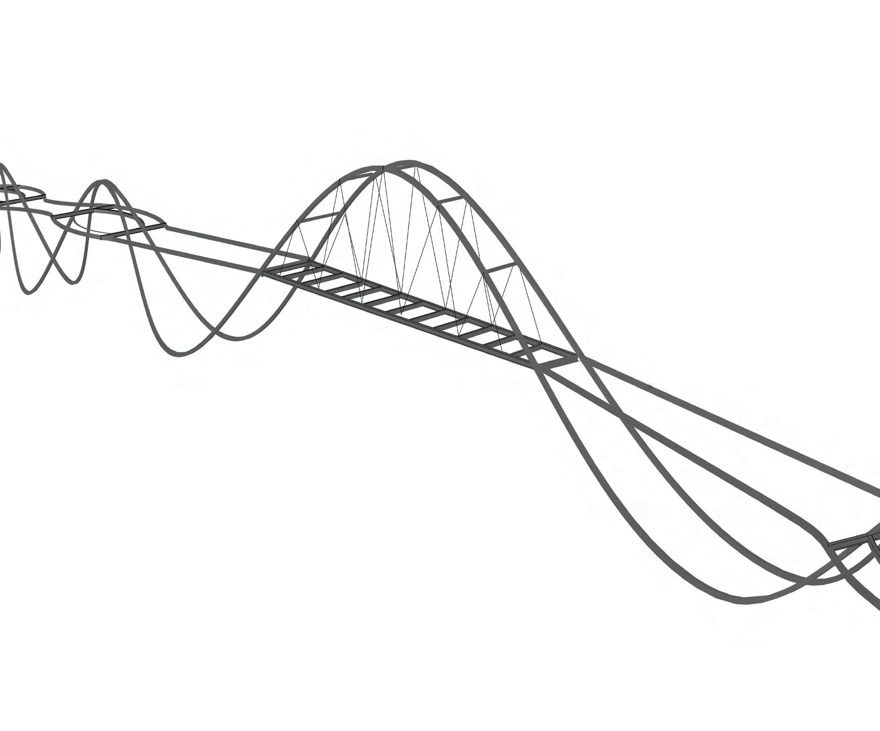
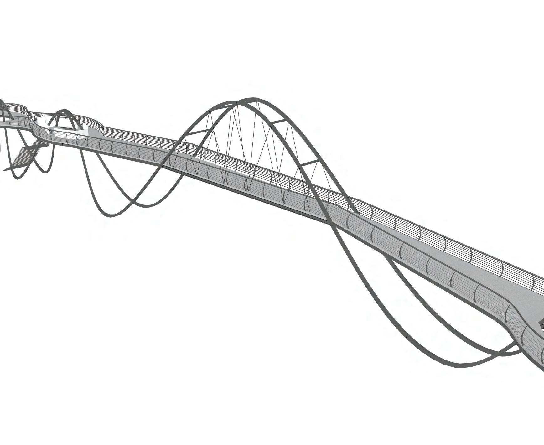
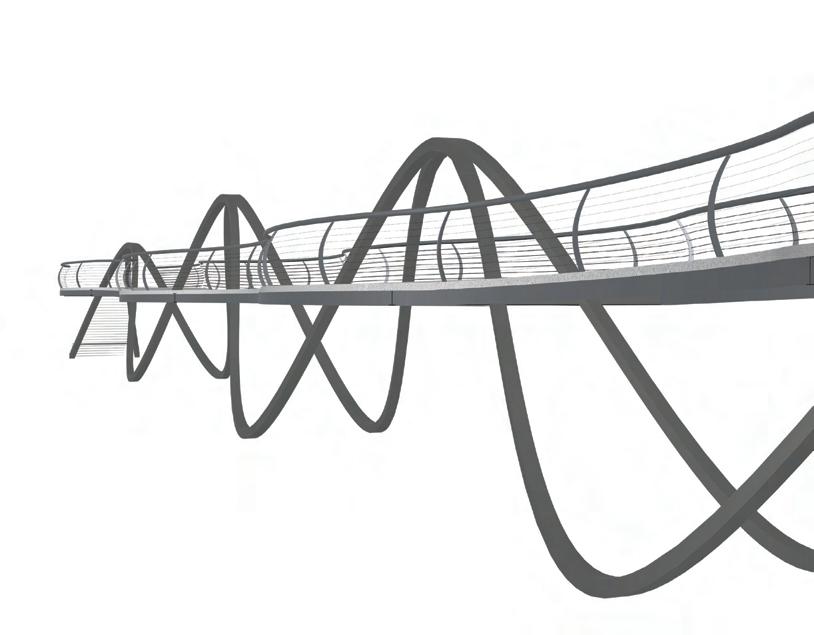
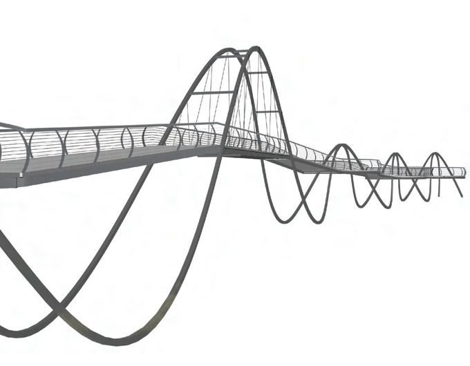
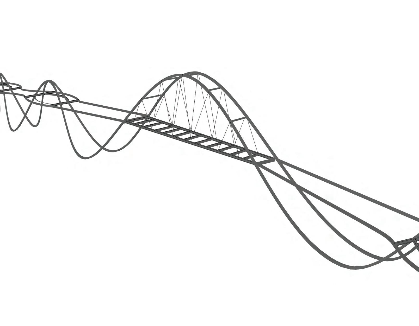
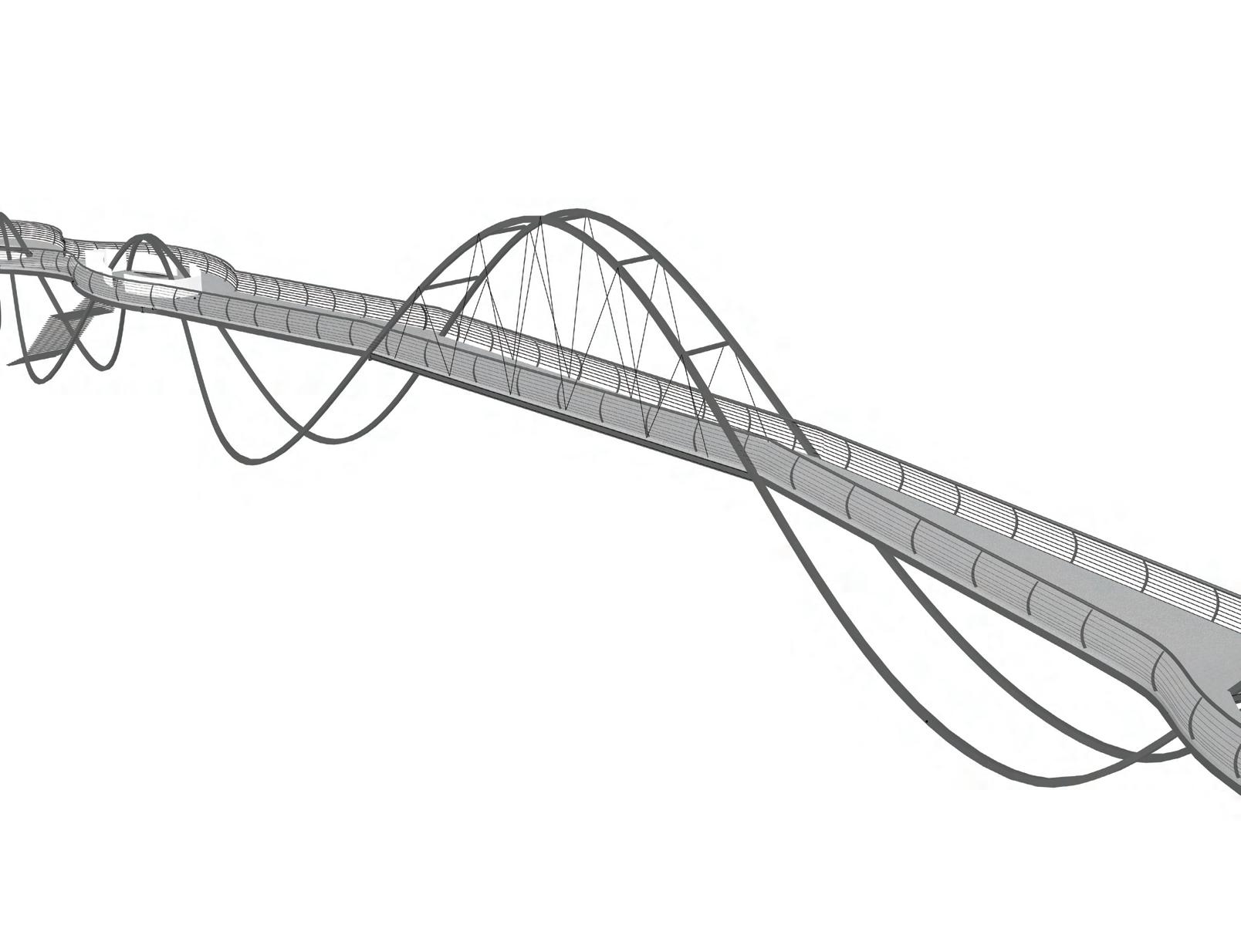
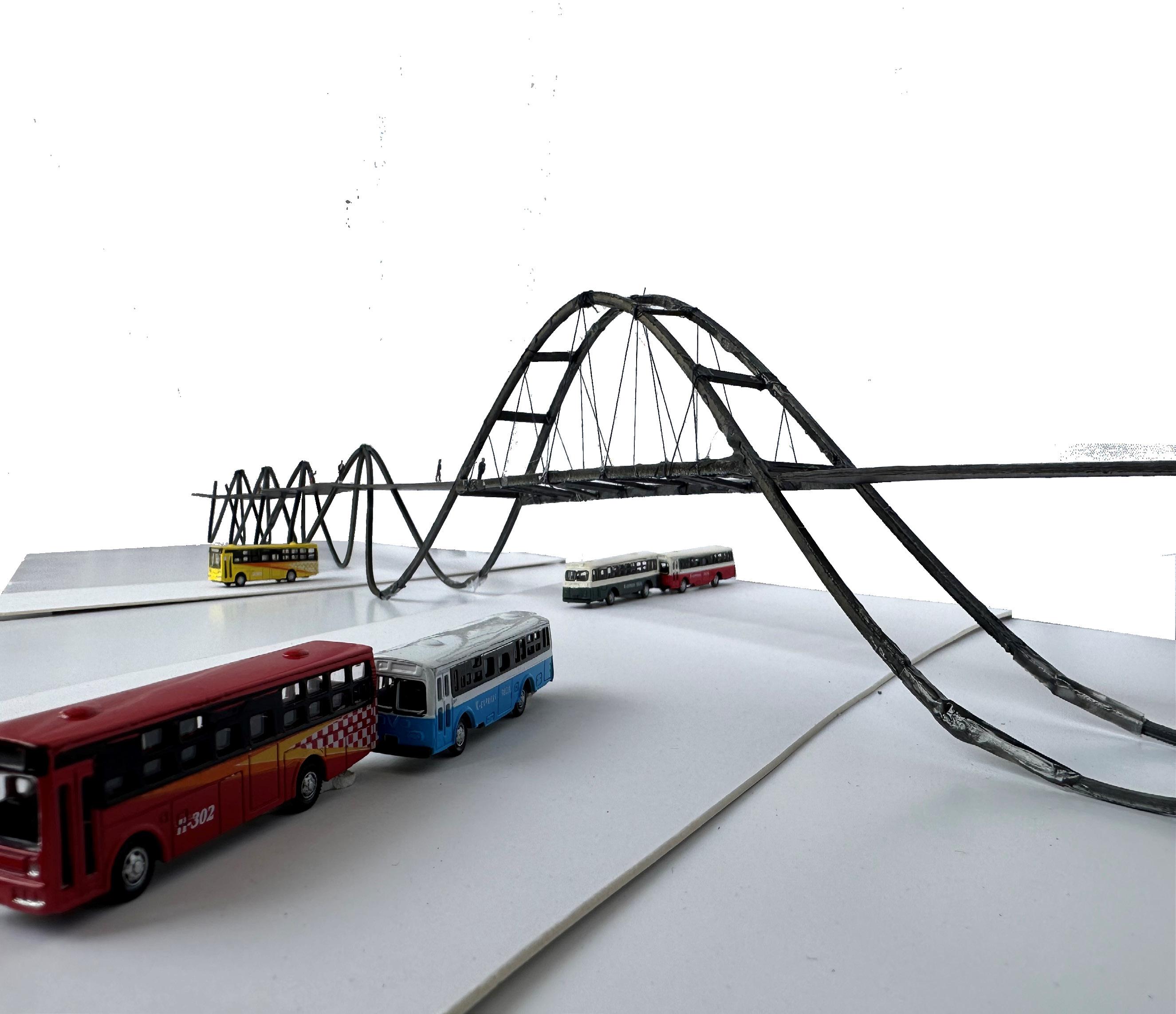
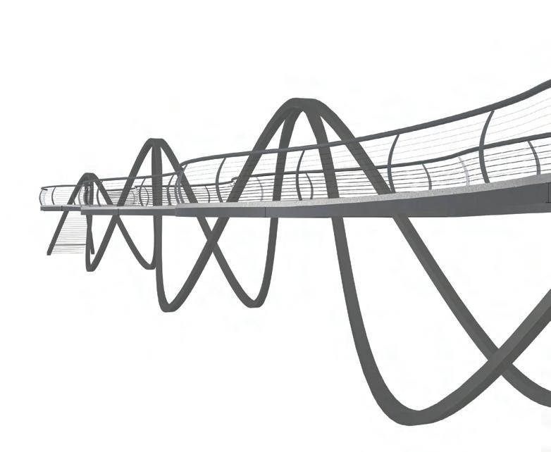
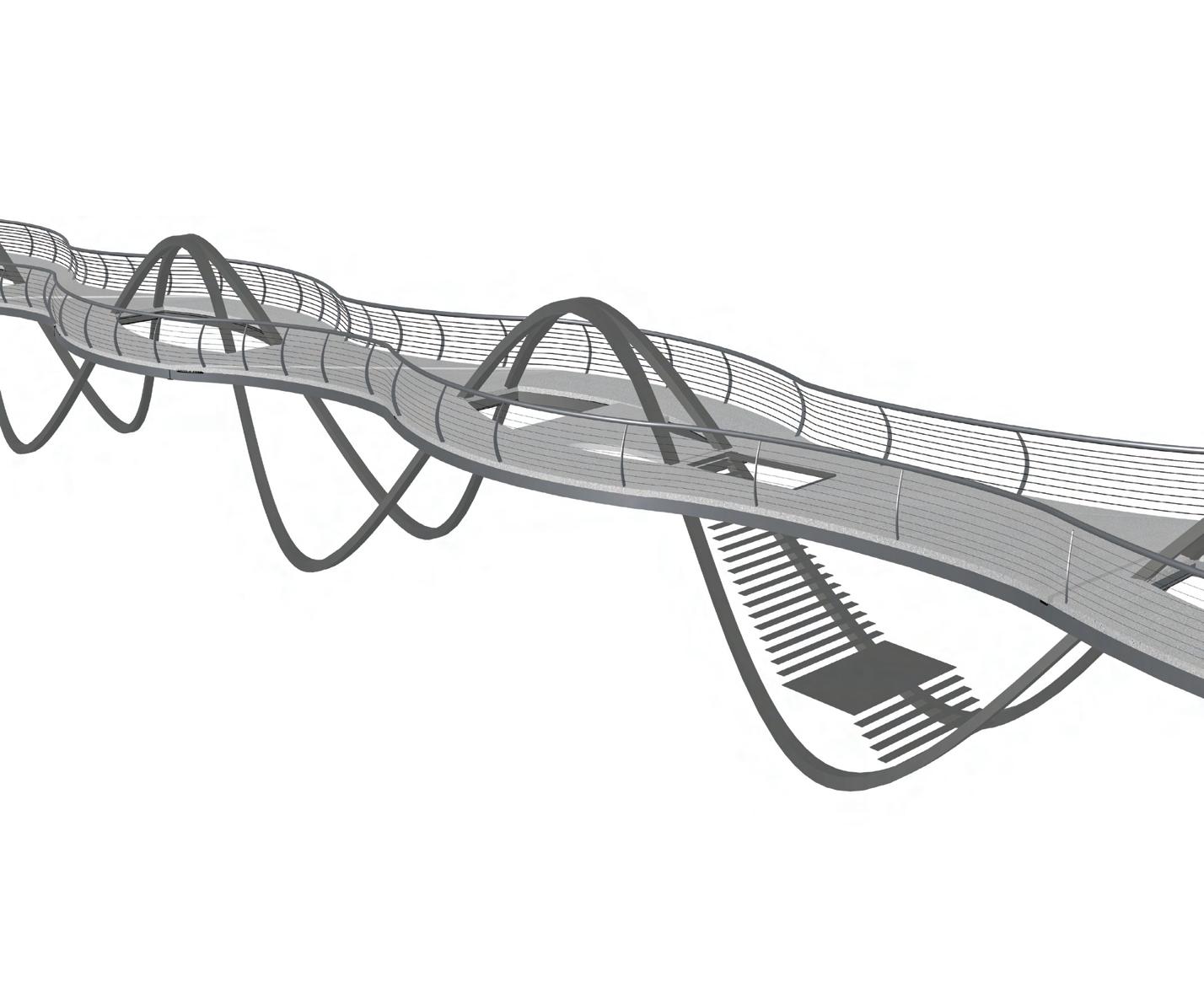
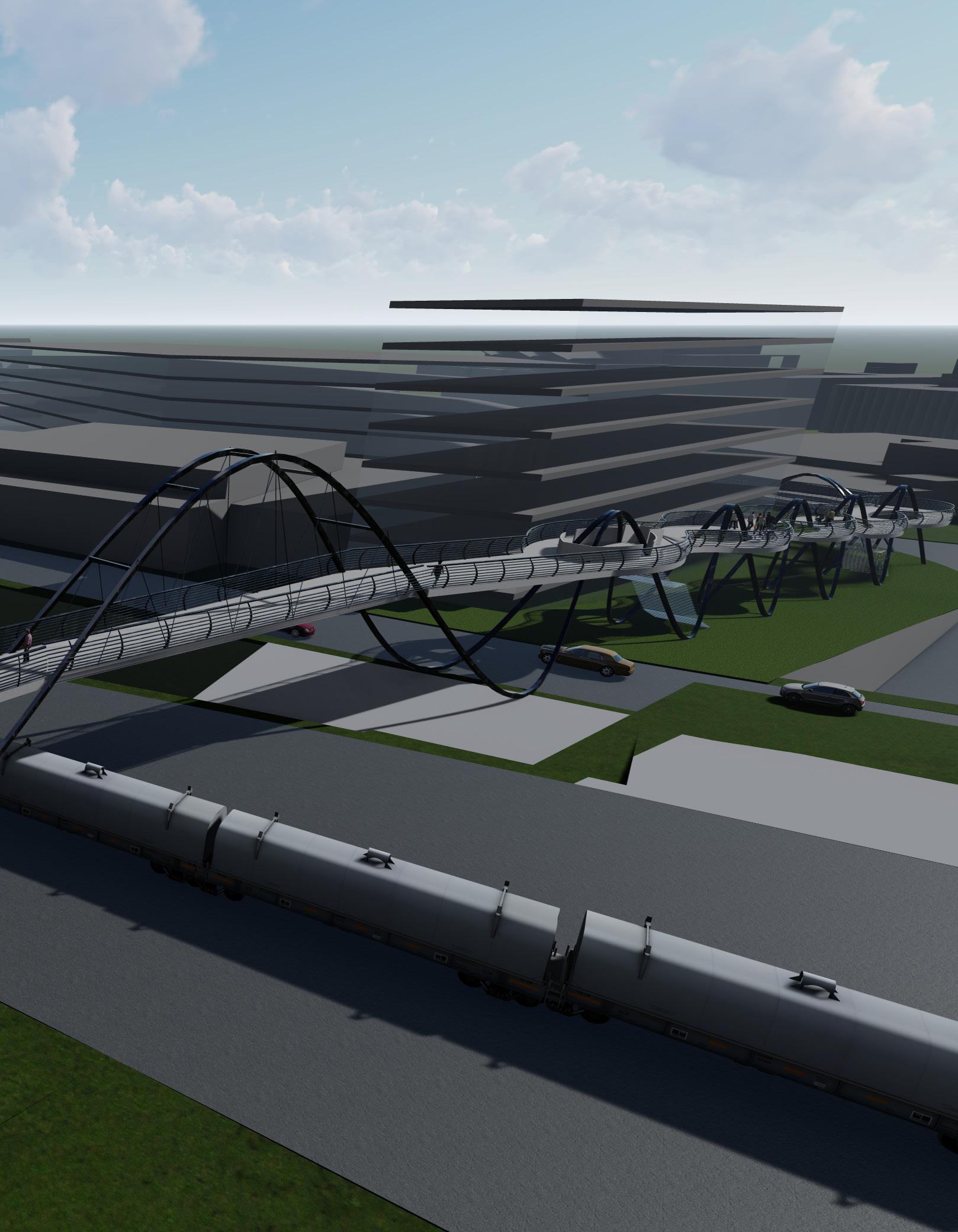
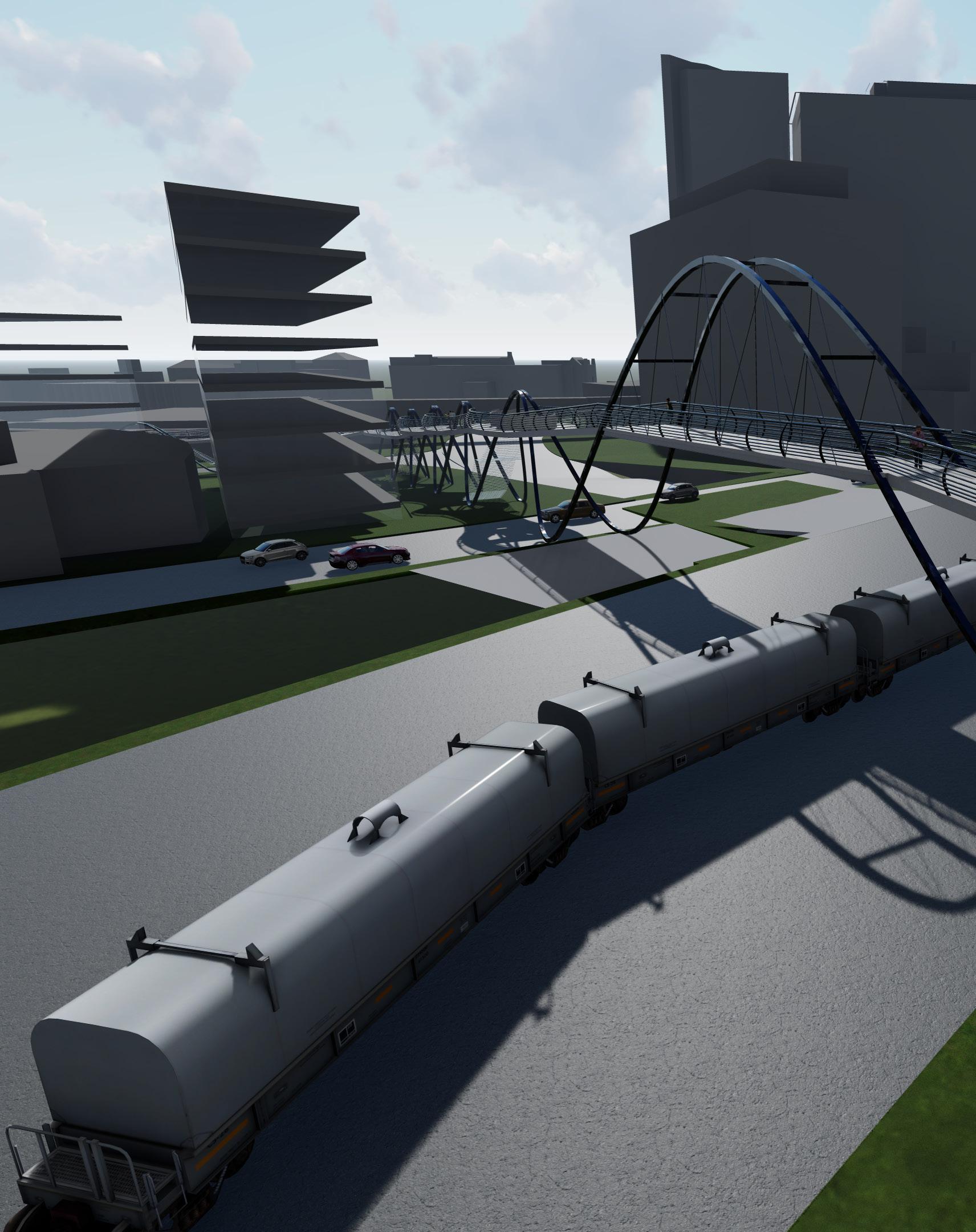
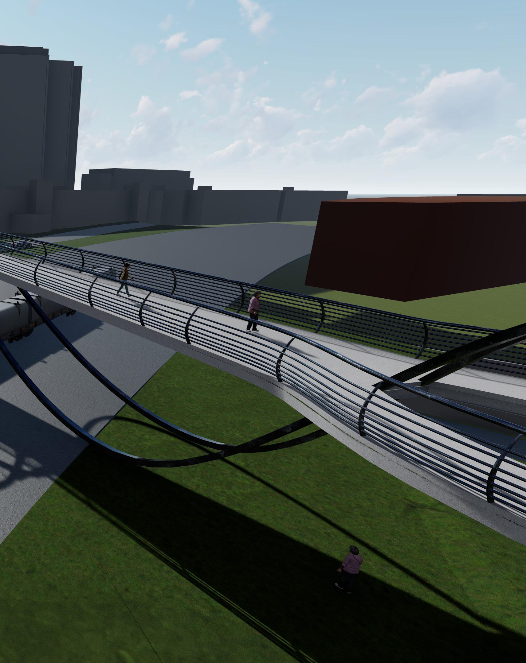
The proposed bridge design connects the heart of the Georgia Tech campus to the Westside community in Atlanta. The design features a safe passage from the student center, spanning over train tracks and reaching North Avenue’s Science Square. It was created through a collaboration between architects and civil engineers, taking into consideration structural details, cost estimation, and material quantity. The bridge is made of steel with a concrete deck and has been designed to showcase a sine wave pattern in both its plan and elevation. The sine wave deck seamlessly integrates with the sine wave steel structure and shows a smooth continuity between short span and long span structure.
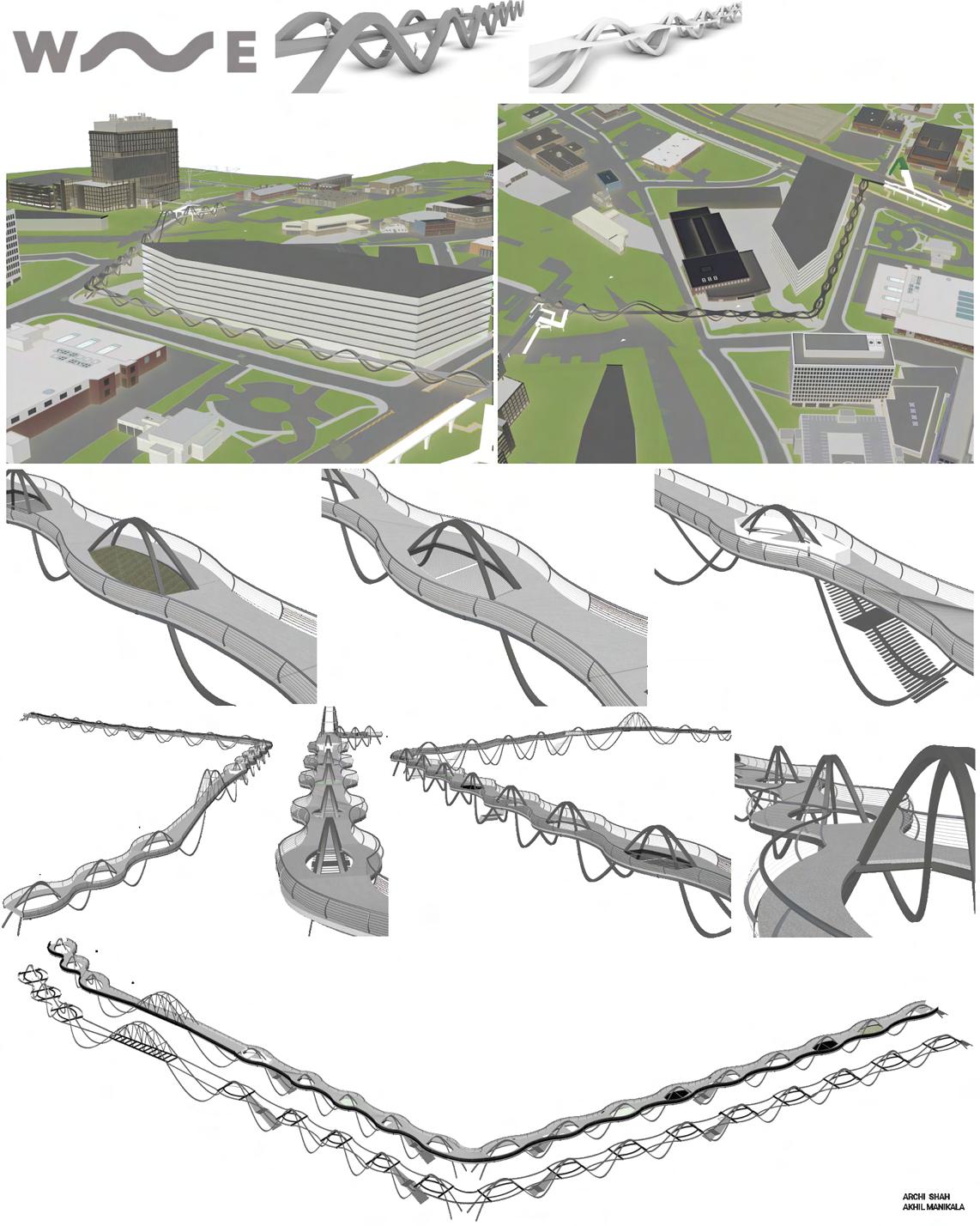
20 20 40 0 60 Wavelength ( 60’) Span Height Span (30’) Amplitude ( 20’) 100 140 180 Structure Deck
INSTRUCTOR
Prof. Daniel Baerlecken | Jim Case | Lauren Stewart
TEAM Akhil Manikala
SINE WAVE | M.Arch | Semester 3 | Fall 2022 7
Physical model made with Steel material


Staircase
Long Span
Hammock
Short Span


 Hammock
9
Green space
showing

W14 x 34 W12 x 16 W6 x 12 W6 x 12 W12 x 16 W14 x 34 SINE WAVE | M.Arch . Semester 3 | Fall 2022
Short span section
Structural members Short span Top view
 Top view of bridge structure
M.Arch Semester 3 | Fall 2022 | SINE WAVE 11
Top view of bridge with deck
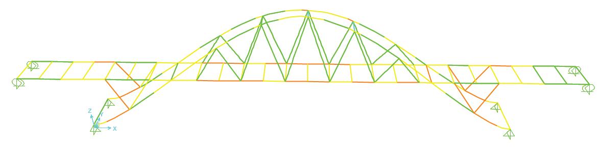
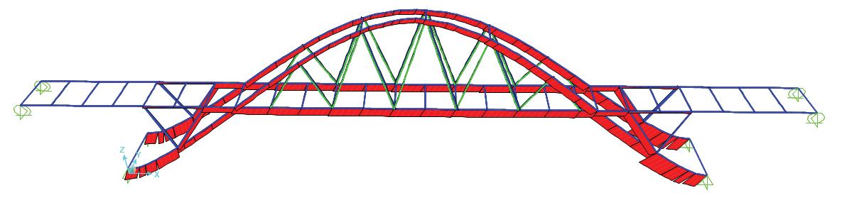
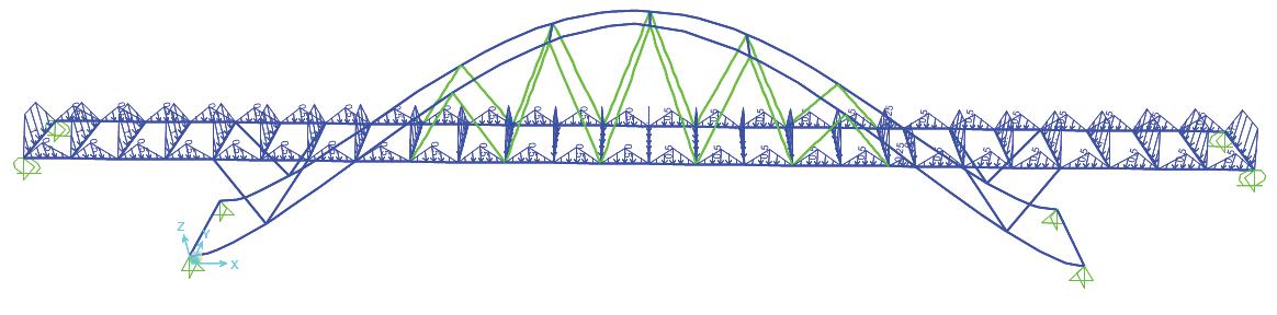
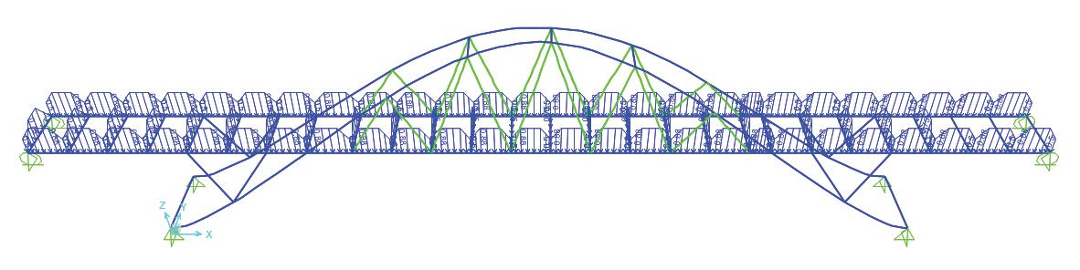
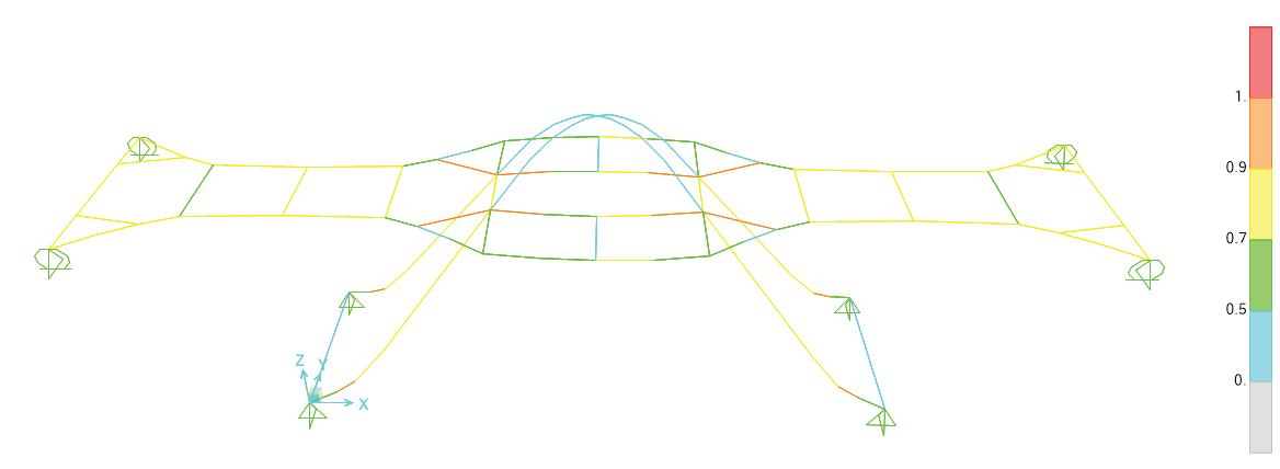
STRUCTURE ANALYSIS
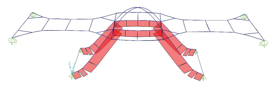

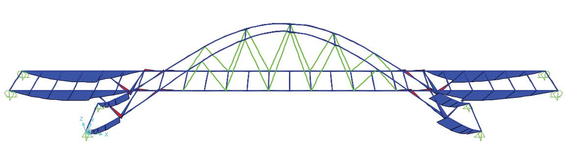
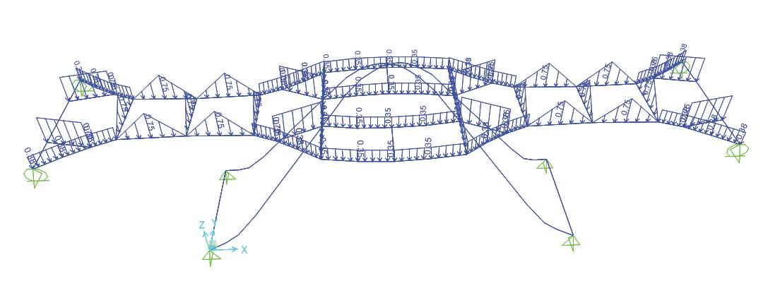
Physical Model Material- Steel


Live Load analysis Stregth ratio analysis
AXIAL FORCE
MOMENT
AXIAL FORCE STRUCTURE ANALYSIS STREGTH RATIO LIVE LOAD DEFLECTED SHAPE BENDING MOMENT DEAD LOAD AXIAL FORCE STRUCTURE ANALYSIS STREGTH RATIO LIVE LOAD BENDING MOMENT DEAD LOAD AXIAL FORCE AXIAL FORCE
BENDING
DEAD LOAD
STREGTH RATIO AXIAL FORCE
SHORT SPAN STRUCTURE ANALYSIS LONG SPAN STRUCTURE ANALYSIS
Bending moment analysis
SINE WAVE | M.Arch | Semester 3 | Fall 2022
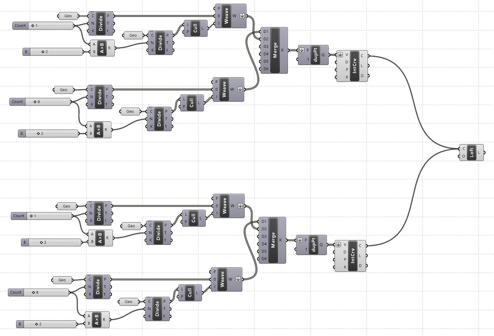
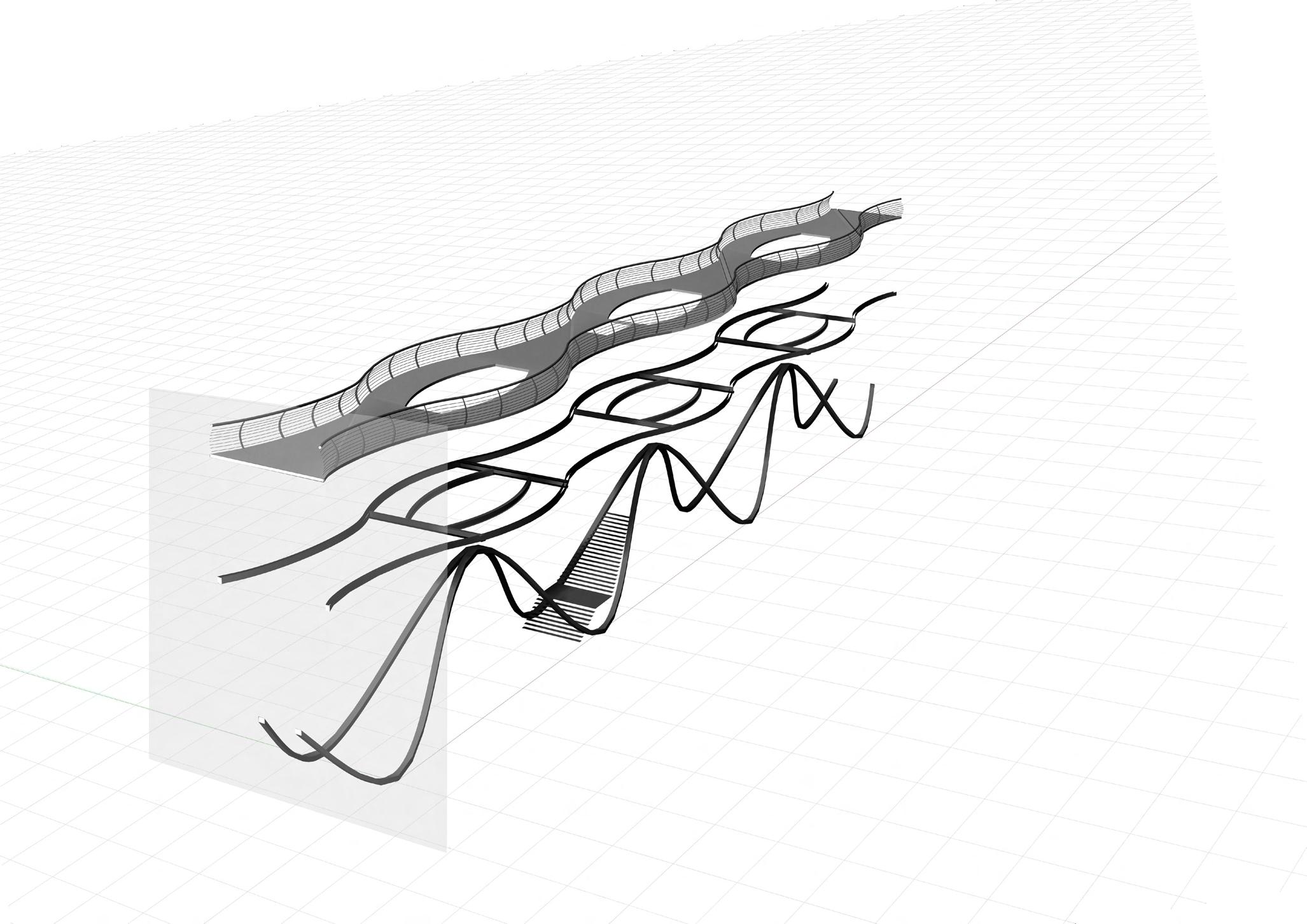

Grasshopper script for structure Exploded view Short span Structure 60ft. 40 ft. W6 x 12 W12 x 16 W14
34 M.Arch Semester 3 | Fall 2022 | SINE WAVE 13
x
15
17
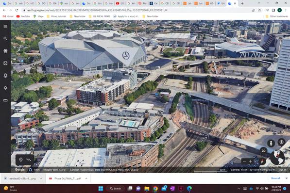
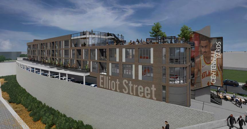
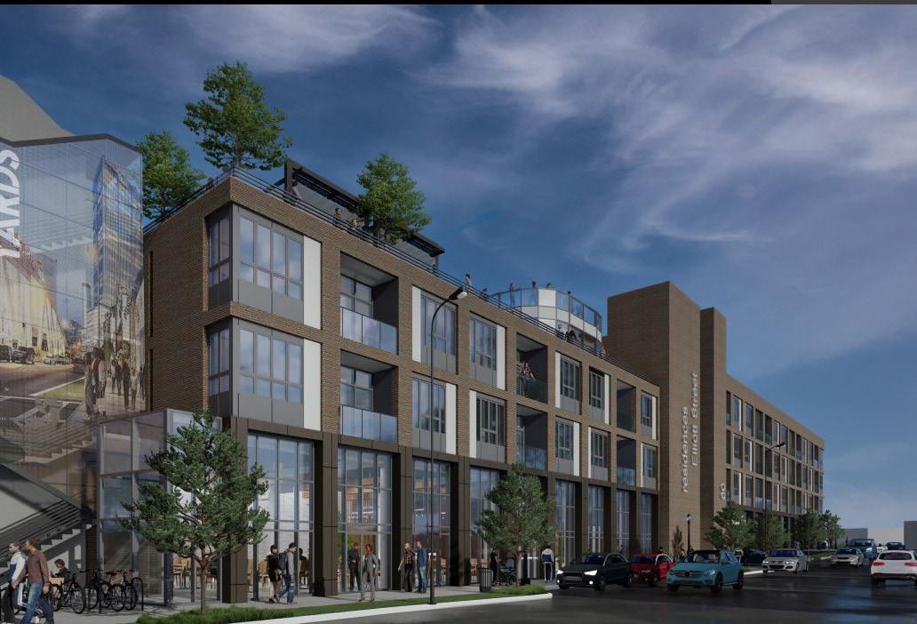
CENTENNIAL YARDS
ARCHITECTURE FIRM

J.W.Robinson & Associates
LOCATION
Atlanta, GA
CLIENT

CIM Group
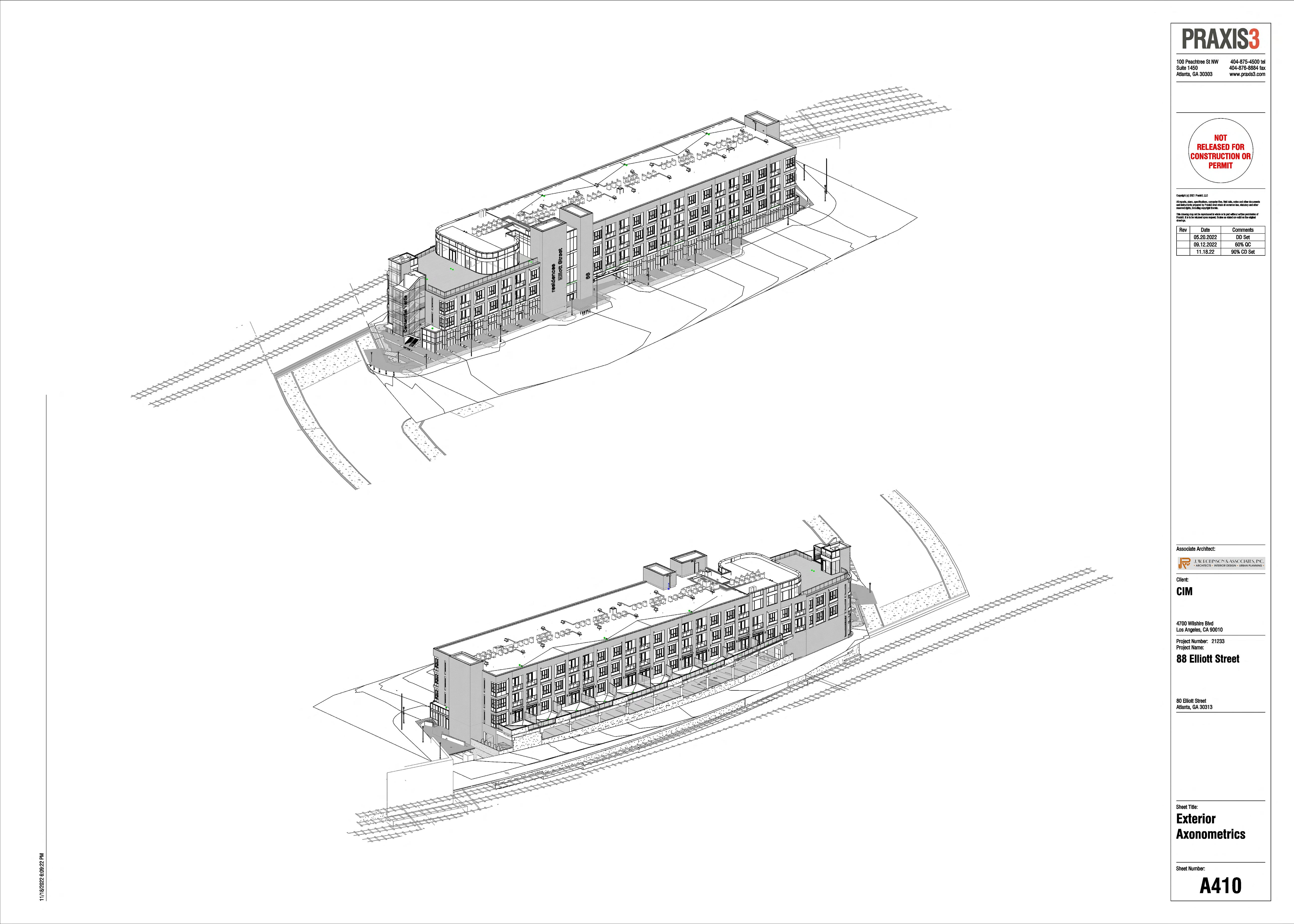
HIGH RISE MIXED USE IN COLLABORATION WITH Praxis3
VISUALIZATIONS
Praxis3
The Centennial Yards project is a multi-faceted development with a budget of $5 Billion. It features a 4-storey residential and retail building located at 88 Elliot St. in downtown Atlanta. The proposed new structure on the 1.09acre site includes retail space and restaurants on the ground floor, 26 on-site surface parking spaces will be located under and behind building. The second and third floors are fully residential, with fourth floor consisting of additional residential units and ample space for a roof terrace and deck accessible to both residents and guests. The residential portions will contain 31 one-bedroom units and 18 two-bedroom residential units. It also includes housing units for the disabled people. Upon completion, the Centennial Yards development will feature up to 12 million square feet across a mix of offices, retail, apartments, and hotels that will rebuild and reconnect forty underutilized acres.
Roles : SD , DD , CD of Residential Units , Interior Designing of Building

UNTAGGED STUD PARTITIONS ARE W030 (TYP).
UNTAGGED MASONRY PARTITIONS ARE W180 (TYP).
DIMENSIONS ARE TO FACE OF STUD OR MASONRY UNO.

GWB & STUD PARTITION
CMU PARTITION
1 HR RATING
2 HR RATING
Grid Legend 100 Peachtree St NW Suite 1450 404-875-4500 tel 404-876-8884 fax PRAXIS3 ALL STUD WALLS SURROUNDING AND WITHIN THE ROOM ARE TO RECEIVE SOUND ATTENUATION INSULATION THE FULL DEPTH AND HEIGHT OF THE STUD CAVITY. SEAL ALL WALL PENETRATIONS. Sound Attenuation Keynotes 1 DN UP TV TV RD
13 A702 4 A403 1 A1.1 222 H FUTURE DINING PATIO Client: Copyright (c) 2021 Praxis3, LLC All reports, plans, specifications, and instruments prepared by Praxis3 reserved rights, including copyright This drawing may not be reproduced Praxis3. It is to be returned upon drawings. Associate Architect: RevDateComments 09.23.2022LDP 11.18.2290% TRUE NORTH 1/16" = 1'-0" A101 2 Second Floor Plan
YARDS
J.W.R | Praxis 3 | Fall 2022
CENTENNIAL
|

CENTENNIAL YARDS | J.W.R | Praxis 3 | Fall 2022
Axon Elliot St.
21
Axon Railyard
UP FE FEC E LE V 1079. 27 B U M U M C M C M S FD FD FE UP DN DN UP UP FEC FEC FEC RD TV T TV TV J J TV FD FD FD FD FD FD FD FD FD FD RD UP DN Partition Legend SEE G010 & G011 FOR PARTITION, FLOOR, & ROOF TYPES. UNTAGGED STUD PARTITIONS ARE W030 (TYP). UNTAGGED MASONRY PARTITIONS ARE W180 (TYP). DIMENSIONS ARE TO FACE OF STUD OR MASONRY UNO. GWB & STUD PARTITION CMU PARTITION 1 HR RATING 2 HR RATING Grid Legend STEEL GRIDLINE -COLUMN CL MASONRY GRIDLINE -F/MASONRY A D B E 1 2 3 4 5 5.5 F G 6 7 8 9 10 11 12 13 152 SF STAIR #2 130 SF ELEV #2 1664 SF 263 SF 157 SF METERS SWITCHBOARD FIRE PUMP STAIR #3 A701 2 A702 2 A400 1 A403 1 A400 2 A703 2 A705 2 A706 2 / 1 A201a 1A201b Matchline A403 2 136 SF OUTDOOR DINING AMENITY/COMMONS AREA LOBBY 225 SF RETAIL B 2.5 2.8 3.5 3.8 4.5 7.3 7.5 8.5 9.5 10.5 11.5 A.8 H A402 1 A402 2 A401 1 A401 2 84'-0 1/4" 21'-3 3/4" 12'-0 1/4" 10'-10 1/8" 34'-1 1/4" 149'-9 3/4" 6'-8 1/4" 312'-1 3/8" 6'-1 7/8" 27'-10 1/8" 21'-3 3/4" 32'-0 1/4" 20'-2 3/4" 63'-0" A708 6 SURFACE PARKING 26 SPACES PROPERTY LINE RETAINING WALL WITH 60" GUARD ABOVE, SEE STRUCTURAL SHEAR WALL, SEE STRUCTURAL SHEAR WALL, SEE STRUCTURAL A708 1 BIKE RACK STORAGE 3 PHASE TRANSFORMER NELSON BRIDGE ELLIOTT STREET MITCHELLSTREETBRIDGE 1058'-0" 1056'-6" 1056'-6" 1055'-3" 1053'-9" PARKING ENTRY WITH ACCESS CONTROL BARRIER ARMS BR CK LEDGE AT RETA NING WALL EXTEND TO MITCHELL STREEET BRIDGE CONNECTION SEE A681 & STRUCTURAL 47'-0" A D B E 1 2 3 4 5 5.5 F G 6 7 8 9 10 11 12 13 A701 4 A702 4 A400 1 A403 1 A400 2 UNIT B1-HC 201 UNIT A2 203 UNIT A2 204 UNIT A2 205 UNIT A1-HC 206 UNIT A2 209 UNIT A1 207 UNIT A2 211 UNIT A1 208 UNIT A1 210 UNIT A2 215 UNIT A1 212 UNIT A2 217 UNIT A1 214 UNIT A2 219 UNIT A1 216 UNIT A1 218 UNIT A1 220 A703 4 A705 3 A706 3 E/D 233 MECH. 232 / 1A202a 1A202b Matchline A403 2 UNIT B3 202 UNIT A3 213 UNIT B2 221 UNIT A1.1 222 2.5 2.8 3.5 3.8 4.5 7.3 7.5 8.5 9.5 10.5 11.5 A.8 H D.1 A.9 E.3 A.1 A.6 E.1 G.1 1.1 3.3 4.7 A402 1 A402 2 A401 1 A401 2 CORRIDOR 200 JAN. 231 STORAGE 230 307'-1 1/4" 61'-11 1/2" A708 2 A708 8 FUTURE DINING PATIO 8'-6" Sheet Number: Project Number: Project Name: Client: Copyright (c) 2021 Praxis3, LLC All reports, plans, specifications, and instruments prepared by Praxis3 Praxis3. It is to be returned upon drawings. 100 Peachtree St Suite 1450 Atlanta, GA 30303 RELEASED CONSTRUCTION Sheet Title: PRAXIS Associate Architect: A101 Overall First (Ground) Second CIM 88 Elliott 80 Elliott Street Atlanta, GA 30313 4700 Wilshire Blvd Los Angeles, CA ALL STUD WALLS SURROUNDING AND WITHIN THE ROOM ARE TO RECEIVE SOUND ATTENUATION INSULATION THE FULL DEPTH AND HEIGHT OF THE STUD CAVITY. SEAL ALL WALL PENETRATIONS. Sound Attenuation Keynotes 1 TRUE NORTH 1/16" = 1'-0" A101 1 First Floor Plan (Ground) RevDateComments 09.23.2022LDP 11.18.2290% TRUE NORTH 1/16" = 1'-0" A101 2 Second Floor Plan Key Plan: FE FEC E LE V : 1079. 27 B U M U M C M C M S FD FD FE UP DN DN UP FEC FEC FEC RD T J J FD FD FD FD FD FD FD FD FD FD RD UP DN Partition Legend SEE G010 & G011 FOR PARTITION, FLOOR, & ROOF TYPES. UNTAGGED STUD PARTITIONS ARE W030 (TYP). UNTAGGED MASONRY PARTITIONS ARE W180 (TYP). DIMENSIONS ARE TO FACE OF STUD OR MASONRY UNO. GWB & STUD PARTITION CMU PARTITION 1 HR RATING 2 HR RATING Grid Legend STEEL GRIDLINE -COLUMN CL MASONRY GRIDLINE -F/MASONRY A D B E 1 2 3 4 5 5.5 F G 6 7 8 9 10 11 12 13 152 SF STAIR #2 TRASH ROOM ELEV #2 RETAIL 263 SF METERS SWITCHBOARD 148 SF 151 SF ELEV #1 A701 2 A702 2 A400 1 A403 1 A400 2 2 A705 2 A706 2 1 A201a 1A201b Matchline A403 2 136 SF OUTDOOR DINING AMENITY/COMMONS AREA RR LOBBY RETAIL B 2.5 2.8 3.5 3.8 4.5 7.3 7.5 8.5 9.5 10.5 11.5 A.8 H A402 1 A402 A401 1 A401 2 84'-0 1/4" 21'-3 3/4" 12'-0 1/4" 10'-10 1/8" 34'-1 1/4" 149'-9 3/4" 6'-8 1/4" 312'-1 3/8" 6'-1 7/8" 27'-10 1/8" 21'-3 3/4" 32'-0 1/4" 20'-2 3/4" 63'-0" A708 6 SURFACE PARKING 26 SPACES PROPERTY LINE RETAINING WALL WITH 60" GUARD ABOVE, SEE STRUCTURAL SHEAR WALL, SEE STRUCTURAL SHEAR WALL, SEE STRUCTURAL A708 BIKE RACK STORAGE 3 PHASE TRANSFORMER NELSON BRIDGE ELLIOTT STREET MITCHELLSTREETBRIDGE 1058'-0" 1056'-6" 1056'-6" 1055'-3" 1053'-9" PARKING ENTRY WITH ACCESS CONTROL BARRIER ARMS BR CK LEDGE AT RETA N NG WALL EXTEND TO MITCHELL STREEET BR DGE CONNECT ON SEE A681 & STRUCTURAL 47'-0" A D B E 1 2 3 4 5 5.5 F G 6 7 8 9 10 11 12 13 A701 4 A702 4 A400 1 A403 1 A400 2 UNIT B1-HC 201 UNIT A2 203 204 UNIT A2 205 UNIT A1-HC 206 UNIT A2 209 UNIT A1 207 UNIT A2 211 UNIT A1 UNIT A1 210 UNIT A2 215 UNIT A1 UNIT A2 217 UNIT A1 214 UNIT A2 219 UNIT A1 UNIT A1 UNIT A1 A703 A705 3 A706 3 E/D 233 MECH. 232 1A202a 1A202b Matchline A403 2 UNIT B3 202 UNIT A3 213 UNIT B2 221 UNIT A1.1 2.5 2.8 3.5 3.8 4.5 7.3 7.5 8.5 9.5 10.5 11.5 A.8 H D.1 A.9 E.3 A.1 A.6 E.1 G.1 1.1 3.3 4.7 A402 1 A402 A401 1 A401 2 CORRIDOR 200 JAN. 231 STORAGE 230 307'-1 1/4" 61'-11 1/2" A708 2 A708 8 FUTURE DINING PATIO 8'-6" Sheet Number: Project Number: Project Name: Client: Copyright (c) 2021 Praxis3, LLC 100 Peachtree St NW Suite 1450 Atlanta, GA 30303 NOT RELEASED FOR CONSTRUCTION PERMIT Sheet Title: 404-875-4500 404-876-8884 www.praxis3.com PRAXIS Associate Architect: A101 Overall Plans First (Ground) Second Floor 21233 CIM 88 Elliott Street 80 Elliott Street Atlanta, GA 30313 4700 Wilshire Blvd Los Angeles, CA 90010 ALL STUD WALLS SURROUNDING AND WITHIN THE ROOM ARE TO RECEIVE SOUND ATTENUATION INSULATION THE FULL DEPTH AND HEIGHT OF THE STUD CAVITY. SEAL ALL WALL PENETRATIONS. Sound Attenuation Keynotes 1 TRUE NORTH 1/16" = 1'-0" A101 1 First Floor Plan (Ground) RevDateComments 09.23.2022LDP 11.18.2290% TRUE NORTH 1/16" = 1'-0" A101 2 Second Floor Plan Key Plan: AB A FEC DN DN UP FEC FEC TV DN UP DN UP DN FEC FEC FEC RD ERD RD ERD RD ERD DN DN A701 5 A702 5 A400 1 A403 1 A400 2 UNIT B1 301 UNIT B3 302 UNIT A2 303 UNIT A2 304 UNIT A2 305 UNIT A2-HC 306 UNIT A2 309 UNIT A2 307 UNIT A2 311 UNIT A2 308 UNIT A3 313 UNIT A2 310 UNIT A2 315 UNIT A2 312 UNIT A2 317 UNIT A2 314 UNIT A2 319 UNIT A2 316 UNIT B2 321 UNIT A2 318 UNIT A2 320 UNIT A2.1 322 A705 4 A703 5 A706 4 E/D 333 MECH. 332 1A203a 2A203a Matchline A403 2 CORRIDOR 300 D.1 A.9 E.3 A.1 A.6 E.1 G.1 1.1 3.3 4.7 A402 1 A402 2 A401 1 A401 2 JAN. 331 STORAGE 330 61'-11 1/2" 307'-1 1/4" 10'-2 1/4" A701 6 A702 6 A400 1 A403 1 A400 2 RETAIL D 401 UNIT A2 407 UNIT A2 409 UNIT A2 408 UNIT A2 411 UNIT A2 410 UNIT A3 413 UNIT A2 412 UNIT A2 415 UNIT A2 414 UNIT A2 417 UNIT A2 416 UNIT A2 419 UNIT A2 418 UNIT B2 421 UNIT A2 420 UNIT A2.1 422 A703 6 A705 5 A706 5 E/D 433 MECH. 432 3A204 2A204 Matchline A403 2 CORRIDOR 400 TRASH 431 STORAGE 430 D.1 A.9 E.3 A.1 A.6 E.1 G.1 1.1 3.3 4.7 A402 1 A402 2 A401 1 A401 2 223'-1 3/4" 61'-11 1/2" A400 2 A.1 1.1 3.3 4.7 A401 1 A401 2 A403 5 A205 4 Sheet Number: Project Number: Project Name: Client: Sheet Title: Associate Overall Third, Roof CIM 88 Elliott 80 Elliott Street Atlanta, GA 4700 Wilshire Los Angeles, TRUE NORTH 1/16" = 1'-0" A102 1 Third Floor Plan RevDateComments 09.23.2022LDP TRUE NORTH 1/16" = 1'-0" A102 2 Fourth Floor Plan 1/16" = 1'-0" A102 3 Roof Terrace Floor Plan Key Plan: FEC DN DN UP FEC FEC TV DN UP DN UP DN FEC FEC FEC RD ERD RD ERD RD ERD DN DN A701 5 A702 5 A400 1 A403 1 A400 2 UNIT B1 301 UNIT B3 302 UNIT A2 303 UNIT A2 304 UNIT A2 305 UNIT A2-HC 306 UNIT A2 309 UNIT A2 307 UNIT A2 311 UNIT A2 308 UNIT A3 313 UNIT A2 310 UNIT A2 315 UNIT A2 312 UNIT A2 317 UNIT A2 314 UNIT A2 319 UNIT A2 316 UNIT B2 321 UNIT A2 318 UNIT A2 320 UNIT A2.1 322 A705 4 A703 5 A706 4 E/D 333 MECH. 332 / 1A203a 2A203a Matchline A403 2 CORRIDOR 300 D.1 A.9 E.3 A.1 A.6 E.1 G.1 1.1 3.3 4.7 A402 1 A402 2 A401 1 A401 2 JAN. 331 STORAGE 330 61'-11 1/2" 307'-1 1/4" 10'-2 1/4" A701 6 A702 6 A400 1 A403 1 A400 2 RETAIL D 401 UNIT A2 407 UNIT A2 409 UNIT A2 408 UNIT A2 411 UNIT A2 410 UNIT A3 413 UNIT A2 412 UNIT A2 415 UNIT A2 414 UNIT A2 417 UNIT A2 416 UNIT A2 419 UNIT A2 418 UNIT B2 421 UNIT A2 420 UNIT A2.1 422 A703 6 A705 5 A706 5 E/D 433 MECH. 432 / 3A204 2A204 Matchline A403 2 CORRIDOR 400 TRASH 431 STORAGE 430 D.1 A.9 E.3 A.1 A.6 E.1 G.1 1.1 3.3 4.7 A402 1 A402 2 A401 1 A401 2 223'-1 3/4" 61'-11 1/2" A400 2 A.1 1.1 3.3 4.7 A401 1 A401 2 A403 5 A205 4 Sheet Number: Project Number: Project Name: Client: reserved rights, including copyright Praxis3. It is be returned upon drawings. Sheet Title: Associate Architect: A102 Overall Third, Roof Plans CIM 88 Elliott 80 Elliott Street Atlanta, GA 30313 4700 Wilshire Blvd Los Angeles, CA TRUE NORTH 1/16" = 1'-0" A102 1 Third Floor Plan RevDateComments 09.23.2022LDP 11.18.2290% TRUE NORTH 1/16" = 1'-0" A102 2 Fourth Floor Plan 1/16" = 1'-0" A102 3 Roof Terrace Floor Plan Key Plan: First Floor Plan (Ground) Second Floor Plan Third Floor Plan Fourth Floor Plan CENTENNIAL YARDS | J.W.R | Praxis 3 | Fall 2022

TYPICAL BRICK ON CFMF ASSEMBLY TYPICAL FCB ON FRT WD. ASSEMBLY TYPICAL FCB ON FRT WD. ASSEMBLY A684 2 A689 7 A680 1A A680 1C A689 10 A686 4 A686 4 A686 2 A686 2 FIRST FLOOR/ RETAIL A 0" SECOND FLOOR 18'-0" THIRD FLOOR 29'-0" FOURTH FLOOR 40'-0" T.O. CHORD 52'-0" G TRUSS BEARING 50'-8 1/2" RETAIL D 401 GENERATOR 115 11'-0" 11'-0" 18'-0" 1'-4" 9'-7 1/4" 4'-5 5/8" 6'-9" 5'-9" 9'-7 1/4" Typical Unit at Podium -Concrete with finish floor as scheduled. -Spray insulation provided at unconditioned areas below. ALL STEEL AT WOOD FRAMING TO BE 1 HOUR FIRE PROTECTED, SEE STRUCTURAL STOREFRONT WALL SYSTEM PARAPET WITH STEEL SUPPORT BR-1 BR-1 BR-1 METAL COPING UNIT UNIT FLOOR/ CEILING ASSEMBLY (FCA-1) SEE FLOOR TYPE SCHEDULE AMENITY 1'-6" RETAIL B 2'-9" RETAIL C 4'-3" G.1 SEE PLAN & SCHEDULE T Y P 2'-0" R-30 MIN. CLOSED CELL SPRAY APPLIED INSULATION FLOOR/ CEILING ASSEMBLY (FCA-1) SEE FLOOR TYPE SCHEDULE FLOOR/ CEILING ASSEMBLY (RCA-4) SEE ROOF TYPE SCHEDULE A680 1A A687 1 A686 6 A689 10 A686 2 A686 4 A686 4 TYPICAL BRICK ON CMU ASSEMBLY A685 2 A689 13 A689 16 A696 8 GEOFOAM INFILL WITH TOPPING SLAB SLOPED TO RETAINING WALL SITE RETAINING WALL, SEE STRUCT. VEHICLE BARRIER WALL T/GYPCRETE T/GYPCRETE FIRST FLOOR/ RETAIL A 0" SECOND FLOOR 18'-0" THIRD FLOOR 29'-0" FOURTH FLOOR 40'-0" T.O. CHORD 52'-0" A TRUSS BEARING 50'-8 1/2" 16'-6" 11'-0" 11'-11 1/2" FLOOR/ CEILING ASSEMBLY (BA-1) SEE FLOOR TYPE SCHEDULE FLOOR/ CEILING ASSEMBLY (RCA-3) SEE FLOOR TYPE SCHEDULE TERRACE BR-1 UNIT UNIT AMENITY 1'-6" RETAIL B 2'-9" RETAIL C 4'-3" A.1 A683 2 TYPICAL MCM ON CFMF ASSEMBLY BALCONY BALCONY METAL COPING R-5 FLOOR/ CEILING ASSEMBLY (PSA-1) SEE FLOOR TYPE SCHEDULE A696 6 A696 7 A683 1 A689 7 A686 12 A686 12 A510 7 A510 8 A695 5 ALL STEEL AT WOOD FRAMING TO BE 1 HOUR FIRE PROTECTED, SEE STRUCTURAL STOREFRONT WALL SYSTEM PARAPET WITH STEEL SUPPORT FLOOR/ CEILING ASSEMBLY (RCA-4) SEE ROOF TYPE SCHEDULE T/GYPCRETE T/GYPCRETE AMENITY/COMMONS AREA 102 3/8" = 1'-0" A651 2 North Wall Section 3/8" = 1'-0" A651 4 North Wall Section at Building Section F 3/8" = 1'-0" A651 3 South Wall Section at Building Section F FIRST FLOOR/ RETAIL A 0" SECOND FLOOR 18'-0" THIRD FLOOR 29'-0" FOURTH FLOOR 40'-0" RETAIL A 120 11'-0" 11'-0" 18'-0" AMENITY 1'-6" RETAIL B 2'-9" RETAIL C 4'-3" Temp. Level 1 0" UNIT B3 202 UNIT B3 302 TYPICAL BRICK ON CFMF ASSEMBLY TYPICAL FCB ON FRT WD. ASSEMBLY TYPICAL FCB ON FRT WD. ASSEMBLY FLOOR/ CEILING ASSEMBLY (RCA-1) SEE FLOOR TYPE SCHEDULE ROOF/ CEILING ASSEMBLY (RCA-3) SEE FLOOR TYPE SCHEDULE A684 2 A689 7 R-5 T.O. STUD 40'-11 1/2" A680 1A A680 1C A689 10 A686 4 A686 4 A686 2 A686 2 T/GYPCRETE T/GYPCRETE 42" DECORATIVE GUARDRAIL, POST SLEEVE MOUNTED TO ROOF DECKING, SEE STRUCTURAL FOR ADDITIONAL BLOCKING REQ. FIRST FLOOR/ RETAIL A 0" SECOND FLOOR 18'-0" THIRD FLOOR 29'-0" FOURTH FLOOR 40'-0" A RETAIL A 120 11'-0" 11'-0" 18'-0" 11 1/2" 1'-5 5/8" 9'-6 3/8" 1'-4 3/4" 9'-7 1/4" 1'-6" FLOOR/ CEILING ASSEMBLY (BA-1) SEE FLOOR TYPE SCHEDULE FLOOR/ CEILING ASSEMBLY (BA-1) SEE FLOOR TYPE SCHEDULE BALCONY BALCONY TERRACE BR-1 MCM-1 SF-1 STEEL BEAM WITH BRAKE METAL COVER TYPICAL BRICK ON WD ASSEMBLY 42" DECORATIVE GUARDRAIL, POST SLEEVE MOUNTED TO ROOF DECKING, SEE STRUCTURAL FOR ADDITIONAL BLOCKING REQ. 2'-5" 3'-6" 1'-0" 9'-7" AMENITY 1'-6" RETAIL B 2'-9" RETAIL C 4'-3" A.1 A689 9 T.O. STUD 40'-11 1/2" ROOF/ CEILING ASSEMBLY (RCA-3) SEE FLOOR TYPE SCHEDULE A680 1 A689 7 A689 18 A686 12 A686 12 A510 7 A510 8 A695 5 A683 17 R-6 R-6 R-5 T/GYPCRETE T/GYPCRETE TYPICAL STOREFRONT ASSEMBLY FIRST FLOOR/ RETAIL A 0" SECOND FLOOR 18'-0" THIRD FLOOR 29'-0" FOURTH FLOOR 40'-0" T.O. CHORD 52'-0" A TRUSS BEARING 50'-8 1/2" 16'-6" 11'-0" 11'-11 1/2" ASSEMBLY SCHEDULE FLOOR/ CEILING ASSEMBLY (RCA-3) SEE FLOOR TYPE SCHEDULE TERRACE BR-1 UNIT AMENITY 1'-6" RETAIL B 2'-9" RETAIL C 4'-3" A683 2 TYPICAL MCM ON CFMF ASSEMBLY BALCONY BALCONY METAL COPING R-5 ASSEMBLY SCHEDULE A683 1 A689 7 A686 12 A686 12 A510 8 A695 5 ALL STEEL AT WOOD FRAMING TO BE 1 HOUR FIRE PROTECTED, SEE STRUCTURAL STOREFRONT WALL SYSTEM PARAPET WITH STEEL SUPPORT T/GYPCRETE T/GYPCRETE AMENITY/COMMONS AREA 102 Sheet Project Project Client: Copyright (c) All reports, and instruments reserved rights, This drawing Praxis3. It drawings. 100 Peachtree Suite Atlanta, Sheet P Associate Wall CIM 88 80 Elliott Atlanta, 4700 Los Angeles, 3/8" = 1'-0" A651 2 North Wall Section at Building Section E 3/8" = 1'-0" A651 1 South Wall Section at Building Section E 1'-0" South Wall Section at Building Section F RevDateComments North Wall section South Wall section Fall 2022 | J.W.R | Praxis 3 | CENTENNIAL YARDS 23
Bathroom Type
6 Kitchen Type A2-Elevation 02 A2-Elevation 01
Bathroom Type B1-HC
Bathroom Type B1-HC
1
LIVING/DINING KITCHEN MECH WD CLOSET BEDROOM BATH 2 L-1 BT-1 CL-4 CL-4 CL-4 5 CL-2 WC-1 1 WH-1 KS-1 2 '0 1 '0 1'-0" A252 8 A252 6 9 7 Sheet Number: Project Number: Project Name: Client: Sheet Title: Associate Architect: A252 Unit A2 & A2.1 Plans & Elevations 21233 CIM 88 Elliott Street 80 Elliott Street Atlanta, GA 30313 4700 Wilshire Blvd Los Angeles, CA 90010 1/4" = 1'-0" A252 1 Unit A2 -Annotation Plan 1. ALL FLOOR PLAN DIMENSIONS ARE TO FACE OF STUD UNLESS NOTED OTHERWISE. "CLEAR" INDICATES DIMENSIONS FROM FINISH FACE TO FINISH FACE OF GYPSUM BOARD. 2. REFLECTED CEILING PLAN DIMENSIONS ARE TAKEN TO FINISH FACE OF GYPSUM BOARD. 3. ALL INTERIOR ELEVATION DIMENSIONS ARE TO FINISH FACE UNLESS NOTED OTHERWISE. 4. ALL PARTITIONS TO BE TYPE W340, U.N.O. 5. PROVIDE 2 1/2 LB FIRE EXTINGUISHER IN EVERY UNIT IN KITCHEN SINK BASE CABINET. 6. AT HARD FINISHED SURFACES FLOOR SOUND MATT MATERIAL W/ GYPCRETE TOPPING IS REQUIRED. SEE UL ASSEMBLY FOR SUBFLOOR CONFIGURATIONS. 7. AT CARPET FINISHED SURFACES ADDITIONAL GYPCRETE TOPPING IS REQUIRED TO ALIGN PRE-FINISHED FLOORING. 8. PROVIDE BLOCKING AT ALL DWELLING UNIT BATHROOM TOILETS, SEE DETAILS. 9. ALL TUB/ SHOWERS TO RECEIVE GRAB BARS PER NFPA 101 CH. 30, SEE DETAILS 10. REFER TO STRUCTURAL DRAWINGS FOR LOAD BEARING WALL CONDITIONS. 11. GYPSUM BOARD SOFFIT IN HEATED SPACE FOR BALCONY SPRINKLER HEAD. LOCATE AT UPPERMOST LEVEL OF EACH UNIT STACK TYP. SEE DETAIL. 12. SEE BUILDING PLANS, ELEVATIONS AND A510 FOR ALL WINDOW & DOOR TYPES. CONDITIONS MAY MIRROR AT EACH FLOOR. HATCH INDICATES 36" FHA & ACCESSIBLE ROUTE 36" REAR, 42" SIDE, AND 18" VERTICAL GRAB BARS AT TOILET (1) 24" @ CONTROL, (2) 24" @ SIDE WALL, (1) 18" @ REAR AND (1) 18" @ CONTROL VERTICALLY GRAB BARS; AT TUB 60" X 30" ADA BATH TUB, TRIM -SHOWER HEAD & CONTROLS W/ HAND HELD SHOWER HEAD ON SLIDE BAR ELONGATED TOILET W/ SEAT MOUNTED AT 18" A.F.F WC-2 HW-8 BT-2 HW-8 General Notes 39" X 39" ADA SHOWER PAN, TRIM -SHOWER HEAD & CONTROLS W/ HAND HELD SHOWER HEAD ON SLIDE BAR SH-3 SCONCE CEILING SURFACE MOUNTED LIGHT PENDANT LIGHT CEILING FAN W/ LIGHT KIT RCP Legend VANITY LIGHT TOILET EXHAUST FAN 1/8" = 1'-0" A252 4 Unit A2 -Finish Plan 1/8" = 1'-0" Unit A2 -FHA Plan CPT-1 LVT-3 T-4 VCT-2 LVT-3 LIVING/DINING KITCHEN CLOSET BEDROOM BATH CLOSET 12" F 3" 27"30"15" 12'-4 1/2" 21" F 6" 15"30"15"36"24" 0" GAP FALL EDGE 1 1/2" WATER 2'-0" 4 2 3 KS-1 CL-1 3 '6 " 1 '6 " 3 '0 " VALENCE & UNDER CABINET LIGHT, TYP. 3 '0 " PL-1 PL-2 PL-1 WT-1 8 '0 " PL-1 SS-1 3 '0 " 1 '6 " 3 '6 " F 3" 24" 27"12" F 3" 12" WT-1 1/4" = 1'-0" A252
10. PROVIDE FOLD-UP SHOWER SEAT IN ADA "HC" SHOWERS 11. SHOWER THRESHOLD TO BE NO HIGHER THAN 1/2". 12. CHANGE IN ELEVATION FROM FINISH FLOOR TO TOP OF PATIO OR BALCONY TO BE NO HIGHER THAN 1/2" 13. SEE INTERIOR ELEVATIONS FOR ALL COUNTER ELEVATION AND MOUNTING HEIGHTS. BT-1 WC-2 L-2 51 54 52 KS-2 SH-3 WC-2 L-2 CL-2 56 WH-1 CL-4 CL-4 CL-4 A256 7 6 8 A256 12 A256 9 13 11 10 5 '6 3 /4 1 6 3 /4 2 1 2 '8 1 /4 2 7 '1 1 3 /4 1'-8" CPT-1 LVT-3 CPT-1 T-4 T-4 VCT-2 KS-2 12" F 3" 27"30"27"15" F 2" 2 '1 0 1 '6 3 '6 24" F 3" 15"30"15" F 5" 24" 2 '1 0 1 '6 3 '6 2 '0 1 '6 2 1 '4 54 52 WT-1 PL-1 PL-2 53 PL-1 SS-1 2 '1 0 1 '6 1 '6 2 3/8" 33" 1" 5/8" 25"24" 2"12" 38"26"12"24" 51 PL-1 PL-2 53 52 3 '6 PL-1 54 WT-1 2 '1 0 Sheet Number: Project Number: Project Name: Client: Copyright (c) 2021 Praxis3, LLC All reports, plans, specifications, computer files, field data, notes and other documents and instruments prepared by Praxis3 shall retain all common law, statutory and other reserved rights, including copyright thereto. This drawing may not be reproduced in whole or in part without written permission of Praxis3. It is to be returned upon request. Scales as stated are valid on the original drawings. PERMIT Sheet Title: Associate Architect: A256 Unit B1-HC Plans & Elevations 21233 CIM 88 Elliott Street 80 Elliott Street Atlanta, GA 30313 4700 Wilshire Blvd Los Angeles, CA 90010 RevDateComments 09.12.202260% QC 11.18.2290% CD Set DOUBLE ROD AND SHELF -WOOD; SEE DETAILS OVER SINK SHELVES -(3) WOOD SHELF; SEE DETAILS VANITY MIRROR W/ J-MOLD AT SIDES CURVED SHOWER ROD WATER HEATER / AIR HANDLER 60" X 30" BATH TUB, TRIM -SHOWER HEAD & CONTROLS ELONGATED TOILET SINGLE ROD AND SHELF -WOOD; SEE DETAILS HAND TOWEL BAR, 18" ABOVE VANITY 1. ALL FLOOR PLAN DIMENSIONS ARE TO FACE OF STUD UNLESS NOTED OTHERWISE. "CLEAR" INDICATES DIMENSIONS FROM FINISH FACE TO FINISH FACE OF GYPSUM BOARD. 2. REFLECTED CEILING PLAN DIMENSIONS ARE TAKEN TO FINISH FACE OF GYPSUM BOARD. 3. ALL INTERIOR ELEVATION DIMENSIONS ARE TO FINISH FACE UNLESS NOTED OTHERWISE. 4. ALL PARTITIONS TO BE TYPE W340, U.N.O. 5. PROVIDE 2 1/2 LB FIRE EXTINGUISHER IN EVERY UNIT IN KITCHEN SINK BASE CABINET. 6. AT HARD FINISHED SURFACES FLOOR SOUND MATT MATERIAL W/ GYPCRETE TOPPING IS REQUIRED. SEE UL ASSEMBLY FOR SUBFLOOR CONFIGURATIONS. 7. AT CARPET FINISHED SURFACES ADDITIONAL GYPCRETE TOPPING IS REQUIRED TO ALIGN PRE-FINISHED FLOORING. 8. PROVIDE BLOCKING AT ALL DWELLING UNIT BATHROOM TOILETS, SEE DETAILS. 9. ALL TUB/ SHOWERS TO RECEIVE GRAB BARS PER NFPA 101 CH. 30, SEE DETAILS 10. REFER TO STRUCTURAL DRAWINGS FOR LOAD BEARING WALL CONDITIONS. 11. GYPSUM BOARD SOFFIT IN HEATED SPACE FOR BALCONY SPRINKLER HEAD. LOCATE AT UPPERMOST LEVEL OF EACH UNIT STACK TYP. SEE DETAIL. 12. SEE BUILDING PLANS, ELEVATIONS AND A510 FOR ALL WINDOW & DOOR TYPES. CONDITIONS MAY MIRROR AT EACH FLOOR. TOILET PAPER HOLDER WH-1 MR-1 WC-1 HW-6 BT-1 HW-3 HW-5 HW-4 HW-7 KS-1 CL-1 CL-2 CL-4 ANSI Type A Unit Keynotes "HC" HATCH INDICATES 36" FHA & ACCESSIBLE ROUTE 32" UNDERMOUNT SINGLE BOWL W/ FAUCET AND INTEGRAL SPRAYER 24" TOWEL BAR, 4' A.F.F ROBE HOOK PANTRY/LINEN SHELVES -(5) WOOD SHELF; SEE DETAILS DISHWASHER -TOP CONTROLS RANGE WITH FRONT CONTROLS COUNTERTOP MICROWAVE SMART ALL-IN-ONE WASHER / DRYER 36" REAR, 42" SIDE, AND 18" VERTICAL GRAB BARS AT TOILET (1) 24" @ CONTROL, (2) 24" @ SIDE WALL, (1) 18" @ REAR AND (1) 18" @ CONTROL VERTICALLY GRAB BARS; AT TUB 60" X 30" ADA BATH TUB, TRIM -SHOWER HEAD & CONTROLS W/ HAND HELD SHOWER HEAD ON SLIDE BAR 51REFRIGERATOR: SIDE-BY-SIDE, SEE OPTIONS RANGE HOOD (RECIRCULATING VENT) -SWITCHED FROM WALL ADJACENT TO RANGE 27" DROP-IN DOUBLE BOWL STAINLESS STEEL SINK 6" DEEP W/ BACK OFFSET DRAIN W/ FAUCET & INTEGRAL SPRAYER ELONGATED TOILET W/ SEAT MOUNTED AT 18" A.F.F 52 53 54 55 56 L-2 WC-2 HW-8 BT-2 HW-8 KS-2 UNDERMOUNT LAVATORY BOWL W/ BACK OFFSET DRAIN, FAUCET, & REMOVABLE BASE CABINET CL-3 General Notes SINGLE ROD AND SHELF -WOOD; SEE DETAILS CL-3 L-1RECTANGULAR UNDERMOUNT SINK BASIN W/ FAUCET PLUMBING FIXTURES APPLIANCES FINISHES & HARDWARE 39" X 39" ADA SHOWER PAN, TRIM -SHOWER HEAD & CONTROLS W/ HAND HELD SHOWER HEAD ON SLIDE BAR SH-3 36" X 36" SHOWER PAN, TRIM -SHOWER HEAD & CONTROLS SH-1 48" X 36" SHOWER PAN, TRIM -SHOWER HEAD & CONTROLS SH-2 SCONCE CEILING SURFACE MOUNTED LIGHT PENDANT LIGHT CEILING FAN W/ LIGHT KIT RCP Legend VANITY LIGHT TOILET EXHAUST FAN 36" X 60" SHOWER PAN, TRIM -SHOWER HEAD & CONTROLS SH-4 1/4" = 1'-0" A256 1 Unit B1-HC -Annotation Plan 1/8" = 1'-0" A256 4 Unit B1-HC -Finish Plan 1/8" = 1'-0" A256 5 Unit B1-HC -FHA-ADA Plan 1/4" = 1'-0" A256 6 Kitchen Type B1-HC -Elevation 02 1/4" = 1'-0" A256 7 Kitchen Type B1-HC -Elevation 01 -Elevation 03 22"15"30"12" F 1" 2 '1 0 " 4 " 4 '0 " 4 " 2'-6" 2'-6" 6'-8" V MR-1 WT-2 PL-2 BT-1 WC-2 L-2 HW-5 HW-4 SS-1 HW-6 U08 V MR-1 L-2 HW-5 V MR-1 4 3/4" F 1/2" 9" 30" 9" F 1" 39" 2 '1 0 " 4 " 4 '0 " 4 " L-2 SH-3 SH-3 WT-2 PL-2 SS-1 2 '9 1 /8 " HW-8 1/4" = 1'-0" A256
9
-Elevation
1/4" = 1'-0" A256
-Elevation 2
12
B1-HC -Elevation
F27 CL-4 CL-4 CL-4 CL-2 CL-4 KS-1 1 WH-1 CL-2 2 5'-1 1/2" CL-2 LIVING/DINING KITCHEN MECH WD BATH BEDROOM BEDROOM CLOSET CLOSET BATH CLOSET L-1 WC-1 WC-1 L-1 BT-1 5 A258 6 7 8 A258 11 12 A258 9 10 F26 F26 General Accessibility and FHA Notes 1. ALL ELECTRICAL AND COMMUNICATIONS CONTROLS AND OUTLETS SHALL BE MOUNTED NO LESS THAN 15" AFF AND NO MORE THAN 48" AFF (INCLUDES THERMOSTAT, SWITCHES, OUTLETS, DATA, PHONE, CABLE, AND ELECTRICAL PANELS). 2. SEE DOOR AND WINDOW SCHEDULES FOR INFORMATION ON OPENING FORCE AND HARDWARE. 3. CONTROLS SHALL BE MOUNTED NO LESS THAN 15" AFF AND NO MORE THAN 48" AFF. 4. AT LEAST 50% OF FREEZER COMPARTMENT ON REFRIGERATOR SHALL BE NO HIGHER THAN 54" AFF. 5. RANGE CONTROLS SHALL BE ON THE FRONT FACE OF APPLIANCE. RANGE MUST BE SELF-CLEANING IN ADA-ACCESSIBLE UNITS. 6. PROVIDE RANGE HOOD CONTROL SWITCH WITHIN REACH RANGE AT ADA-ACCESSIBLE UNITS. 7. PROVIDE GARBAGE DISPOSAL SWITCH WITHIN REACH RANGES, AND WITHIN SINK CABINET FOR ADAACCESSIBLE UNITS. 8. PROVIDE SHOWER SPRAY HANDHELD UNIT ON SLIDE BAR WITH MINIMUM 59" HOSE. MOUNT BOTTOM OF DEVICE MOUNT ON SLIDE BAR NO HIGHER THAN 48" AFF. 9. PROVIDE GRAB BARS AT ADA-ACCESSIBLE UNIT SHOWERS AND SHOWER/TUB COMBOS, AND COMMODES. PROVIDE IN-WALL BLOCKING AT ALL OTHER(ADAPTABLE) UNITS SHOWERS AND SHOWER/TUB COMBOS, AND COMMODES FOR GRAB-BARS PER GA R&R 120-3-3, MODIFICATION 30.2.1.3. 10. PROVIDE FOLD-UP SHOWER SEAT IN ADA "HC" SHOWERS 11. SHOWER THRESHOLD TO BE NO HIGHER THAN 1/2". 12. CHANGE IN ELEVATION FROM FINISH FLOOR TO TOP OF PATIO OR BALCONY TO BE NO HIGHER THAN 1/2" 13. SEE INTERIOR ELEVATIONS FOR ALL COUNTER ELEVATION AND MOUNTING HEIGHTS. UNDER CABINET LIGHTS, TYP. WET RATED LIVING/DINING KITCHEN MECH W/D BATH BEDROOM BEDROOM CLOSET CLOSET BATH 5 0 3 /8 6 '0 4 '5 3 /8 4 '9 1 /2 E Q E Q 2'-11 1/8"3'-1 1/8" 2 '1 1 1 /8 E Q E Q EQEQ 2 '3 1 /2 EQEQ 1 '1 0 E Q E Q 1'-3" 5'-1 5/8" 5'-3 5/8" 4'-0 1/2"4'-0" 4'-0" 5'-8 1/8" 5'-1 11/16" 5'-3 11/16" 5 '2'-10"2'-4 3/4" 2'-3 5/8" 2'-8 5/8" 6 '0 5'-0" 5'-0" 3'-0" 1'-6" 1'-9 1/2" WET RATED E Q E Q 2 '4 E Q E Q 2'-8" 1'-10" 33 1" 12"30" 15" 18 1/2" 36" 2 '1 0 4 4 '0 4 MR-1 PL-2 V WC-1 HW-6 1 '6 5 0 SS-1 HW-4 HW-5 L-1 WT-2 Sheet Number: Project Number: Project Name: Client: Copyright (c) 2021 Praxis3, LLC All reports, plans, specifications, computer files, field data, notes and other documents and instruments prepared by Praxis3 shall retain all common law, statutory and other reserved rights, including copyright thereto. This drawing may not be reproduced in whole or in part without written permission of Praxis3. is to be returned upon request. Scales as stated are valid on the original drawings. 100 Peachtree St NW Suite 1450 Atlanta, GA 30303 NOT RELEASED FOR CONSTRUCTION OR PERMIT Sheet Title: 404-875-4500 tel 404-876-8884 fax www.praxis3.com PRAXIS3 Associate Architect: A258 Unit B3 Plans & Elevations 21233 CIM 88 Elliott Street 80 Elliott Street Atlanta, GA 30313 4700 Wilshire Blvd Los Angeles, CA 90010 RevDateComments 09.12.202260% QC 11.18.2290% CD Set 1/4" = 1'-0" A258 1 Unit B3 -Annotation Plan Unit Plan Keynotes REFRIGERATOR: SIDE-BY-SIDE, SEE OPTIONS 24" DISHWASHER 1 30" RANGE W/ FRONT CONTROLS VANITY -2CM COUNTERTOP W/ 4" TALL BACKSPLASH DOUBLE ROD AND SHELF -WOOD; SEE DETAILS MICROWAVE HOOD COMBINATION (RECIRCULATING VENT) OVER SINK SHELVES -(3) WOOD SHELF; SEE DETAILS VANITY MIRROR W/ J-MOLD AT SIDES CURVED SHOWER ROD WATER HEATER AIR HANDLER 60" X 30" BATH TUB, TRIM -SHOWER HEAD & CONTROLS ELONGATED TOILET SINGLE ROD AND SHELF -WOOD; SEE DETAILS HAND TOWEL BAR, 18" ABOVE VANITY 1. ALL FLOOR PLAN DIMENSIONS ARE TO FACE OF STUD UNLESS NOTED OTHERWISE. "CLEAR" INDICATES DIMENSIONS FROM FINISH FACE TO FINISH FACE OF GYPSUM BOARD. 2. REFLECTED CEILING PLAN DIMENSIONS ARE TAKEN TO FINISH FACE OF GYPSUM BOARD. 3. ALL INTERIOR ELEVATION DIMENSIONS ARE TO FINISH FACE UNLESS NOTED OTHERWISE. 4. ALL PARTITIONS TO BE TYPE W340, U.N.O. 5. PROVIDE 2 1/2 LB FIRE EXTINGUISHER IN EVERY UNIT IN KITCHEN SINK BASE CABINET. 6. AT HARD FINISHED SURFACES FLOOR SOUND MATT MATERIAL W/ GYPCRETE TOPPING IS REQUIRED. SEE UL ASSEMBLY FOR SUBFLOOR CONFIGURATIONS. 7. AT CARPET FINISHED SURFACES ADDITIONAL GYPCRETE TOPPING IS REQUIRED TO ALIGN PRE-FINISHED FLOORING. 8. PROVIDE BLOCKING AT ALL DWELLING UNIT BATHROOM TOILETS, SEE DETAILS. 9. ALL TUB/ SHOWERS TO RECEIVE GRAB BARS PER NFPA 101 CH. 30, SEE DETAILS 10. REFER TO STRUCTURAL DRAWINGS FOR LOAD BEARING WALL CONDITIONS. 11. GYPSUM BOARD SOFFIT IN HEATED SPACE FOR BALCONY SPRINKLER HEAD. LOCATE AT UPPERMOST LEVEL OF EACH UNIT STACK TYP. SEE DETAIL. 12. SEE BUILDING PLANS, ELEVATIONS AND A510 FOR ALL WINDOW & DOOR TYPES. CONDITIONS MAY MIRROR AT EACH FLOOR. TOILET PAPER HOLDER WASHER/DRYER STACK, SEE OPTIONS 2CM COUNTERTOP SS-1 3 2 4 5 WH-1 SS-2 MR-1 WC-1 HW-6 BT-1 HW-3 HW-5 HW-4 HW-7 KS-1 CL-1 CL-2 CL-4 ANSI Type A Unit Keynotes "HC" HATCH INDICATES 36" FHA & ACCESSIBLE ROUTE 32" UNDERMOUNT SINGLE BOWL W/ FAUCET AND INTEGRAL SPRAYER 24" TOWEL BAR, 4' A.F.F ROBE HOOK PANTRY/LINEN SHELVES -(5) WOOD SHELF; SEE DETAILS DISHWASHER -TOP CONTROLS RANGE WITH FRONT CONTROLS COUNTERTOP MICROWAVE SMART ALL-IN-ONE WASHER / DRYER 36" REAR, 42" SIDE, AND 18" VERTICAL GRAB BARS AT TOILET (1) 24" @ CONTROL, (2) 24" @ SIDE WALL, (1) 18" @ REAR AND (1) 18" @ CONTROL VERTICALLY GRAB BARS; AT TUB 60" X 30" ADA BATH TUB, TRIM -SHOWER HEAD & CONTROLS W/ HAND HELD SHOWER HEAD ON SLIDE BAR 51REFRIGERATOR: SIDE-BY-SIDE, SEE OPTIONS RANGE HOOD (RECIRCULATING VENT) -SWITCHED FROM WALL ADJACENT TO RANGE 27" DROP-IN DOUBLE BOWL STAINLESS STEEL SINK 6" DEEP W/ OFFSET DRAIN W/ FAUCET & INTEGRAL SPRAYER ELONGATED TOILET W/ SEAT MOUNTED AT 18" A.F.F 52 53 54 55 56 L-2 WC-2 HW-8 BT-2 HW-8 KS-2 UNDERMOUNT LAVATORY BOWL W/ BACK OFFSET DRAIN, FAUCET, & REMOVABLE BASE CABINET CL-3 General Notes SINGLE ROD AND SHELF -WOOD; SEE DETAILS CL-3 FINISHES & HARDWARE L-1RECTANGULAR UNDERMOUNT SINK BASIN W/ FAUCET PLUMBING FIXTURES APPLIANCES APPLIANCES FINISHES & HARDWARE 39" X 39" ADA SHOWER PAN, TRIM -SHOWER HEAD & CONTROLS W/ HAND HELD SHOWER HEAD ON SLIDE BAR SH-3 36" X 36" SHOWER PAN, TRIM -SHOWER HEAD & CONTROLS SH-1 48" X 36" SHOWER PAN, TRIM -SHOWER HEAD & CONTROLS SH-2 SCONCE CEILING SURFACE MOUNTED LIGHT PENDANT LIGHT CEILING FAN W/ LIGHT KIT RCP Legend VANITY LIGHT TOILET EXHAUST FAN TUB SHOWER WALL TILE SURROUND WT-2 KITCHEN WALL TILE BACKSPLASH WT-1 36" X 60" SHOWER PAN, TRIM -SHOWER HEAD & CONTROLS SH-4 1/4" = 1'-0" A258 3 Unit B3 -RCP 1/4" = 1'-0" A258 9 Bathroom 1a 3 '0 " 1 '6 " 1 '6 " 2 '0 " 8 '0 " 4 2 F 3" 33" F 1" 5/8" 24"24" F 6" 12" PL-1 1 37" 5/8" 24"15" F 3" 24" PL-2 SS-1 PL-1 WT-1 2 4 KS-1 18"30"18" F 3" 24" 3 '6 " 1 '6 " 30"30" 0" 18" 2 4 " 3 6 " 10"
CABINET LIGHT, TYP. PL-1 7'-9" W360 PL-1 PL-2 CL-1 WT-1 2'-4" 15"12"30"12" 1" 4 " 4 '0 " 4 " 2 '1 0 " V MR-1 PL-2 1 '6 " HW-5 L-1 SS-1 33 HW-4 28 WT-2 6 Kitchen 01 Kitchen 02 1'-0" Bathroom 2a 1/4" = 1'-0" A258 10 Bathroom 1b Unit A2 1 Bed 1 Bath Plan & Elevation Unit B1 Hancap 2 Bed 2 Bath Plan & Elevation Unit B3 2 Bed 2 Bath Plan & Elevation CENTENNIAL YARDS | J.W.R | Praxis 3 | Fall 2022
01 Type B1-HC -Elevation 02
VALENCE & UNDER
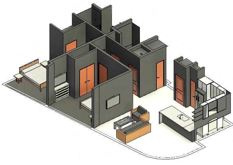
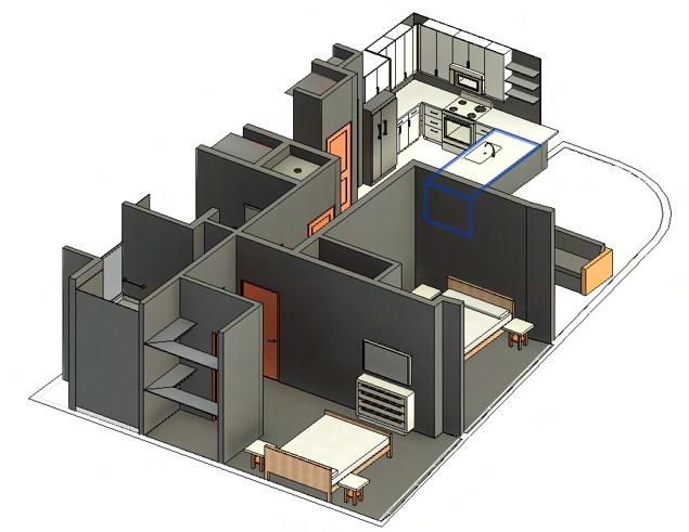

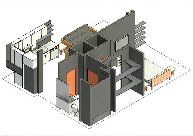
3-Dimensional
Unit B3
3-Dimensional
3-Dimensional Fall 2022 | J.W.R | Praxis 3 | CENTENNIAL YARDS 25
Unit B1 Handicap
Unit A2
BUOYANCY

CHANGING FORM BY FORCE
COLLEGE
Georgia Institute of Technology
LOCATION
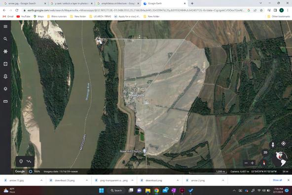
Mayersville , Mississippi
Friday, January 27, 2023 6:25 PM
Friday, January 27, 2023 6:25 PM


INSTRUCTOR
Prof. Heather Potts
MODULE


Portman Design Studio

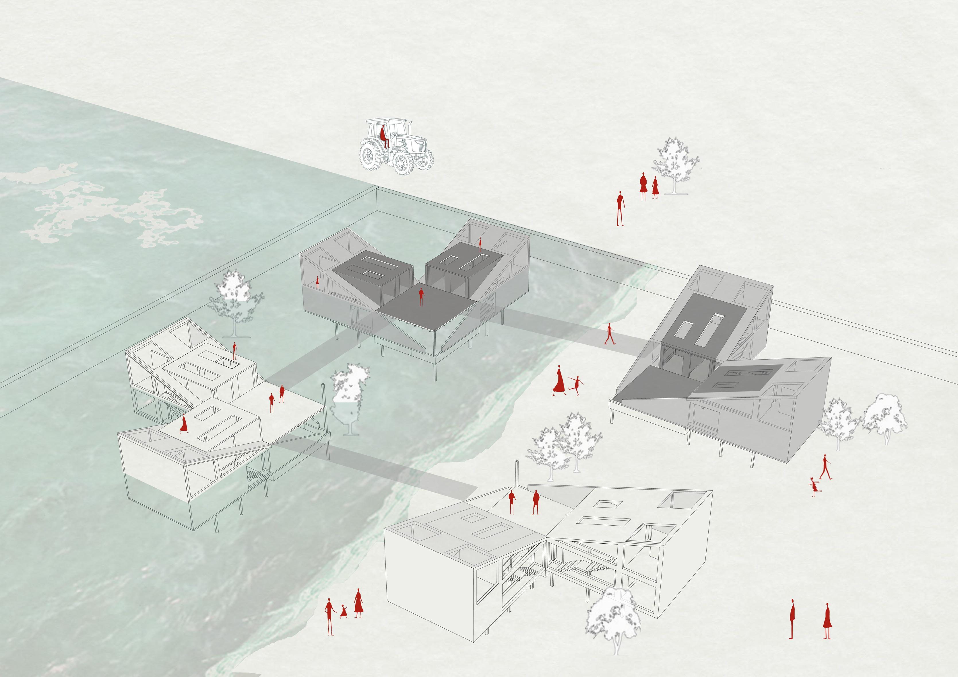

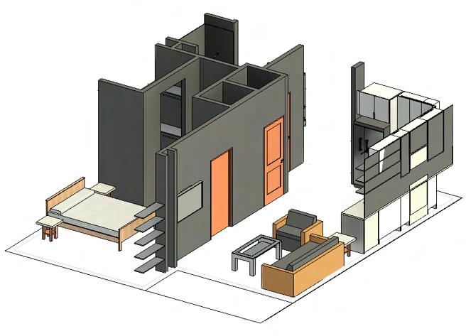
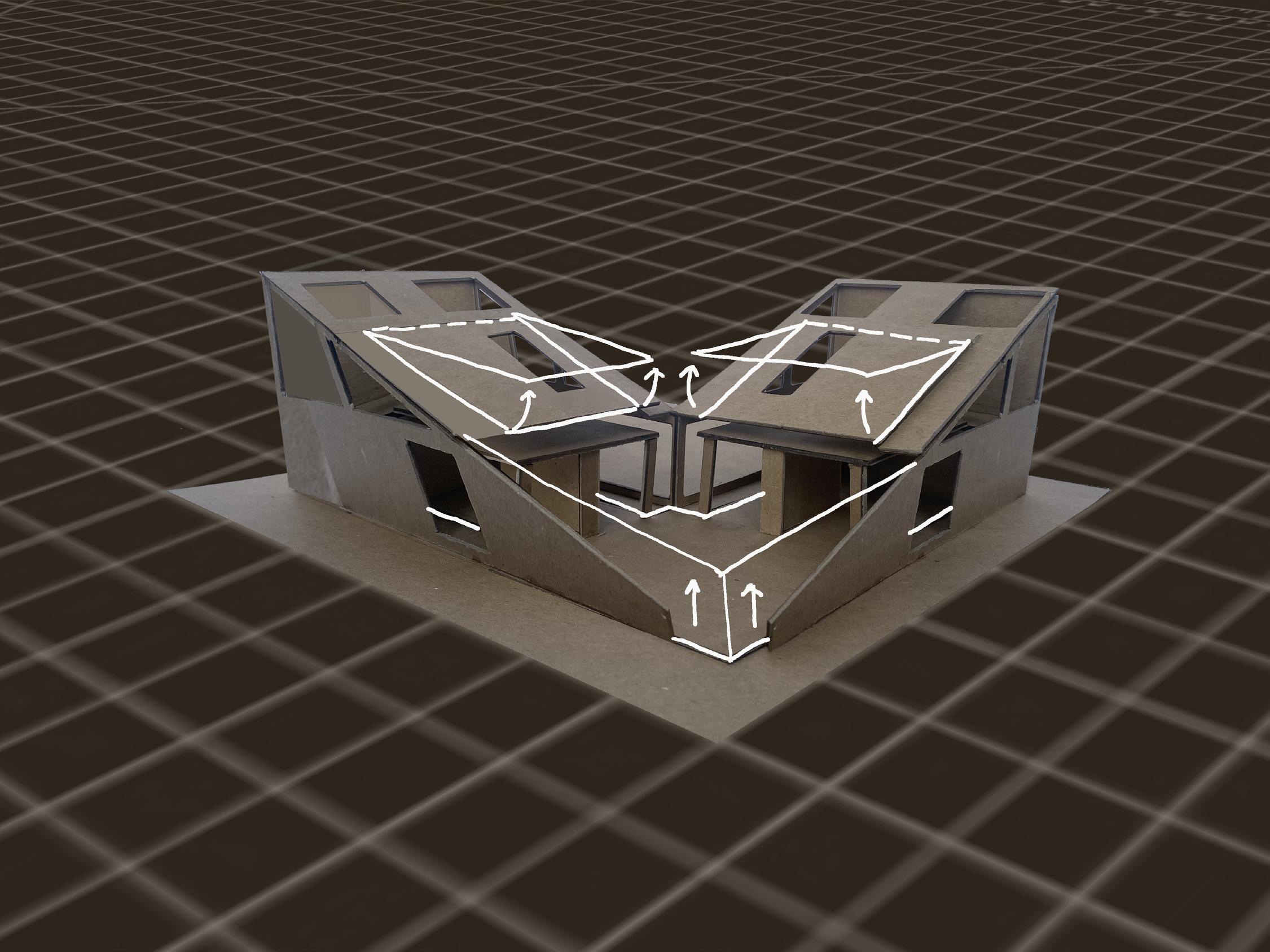
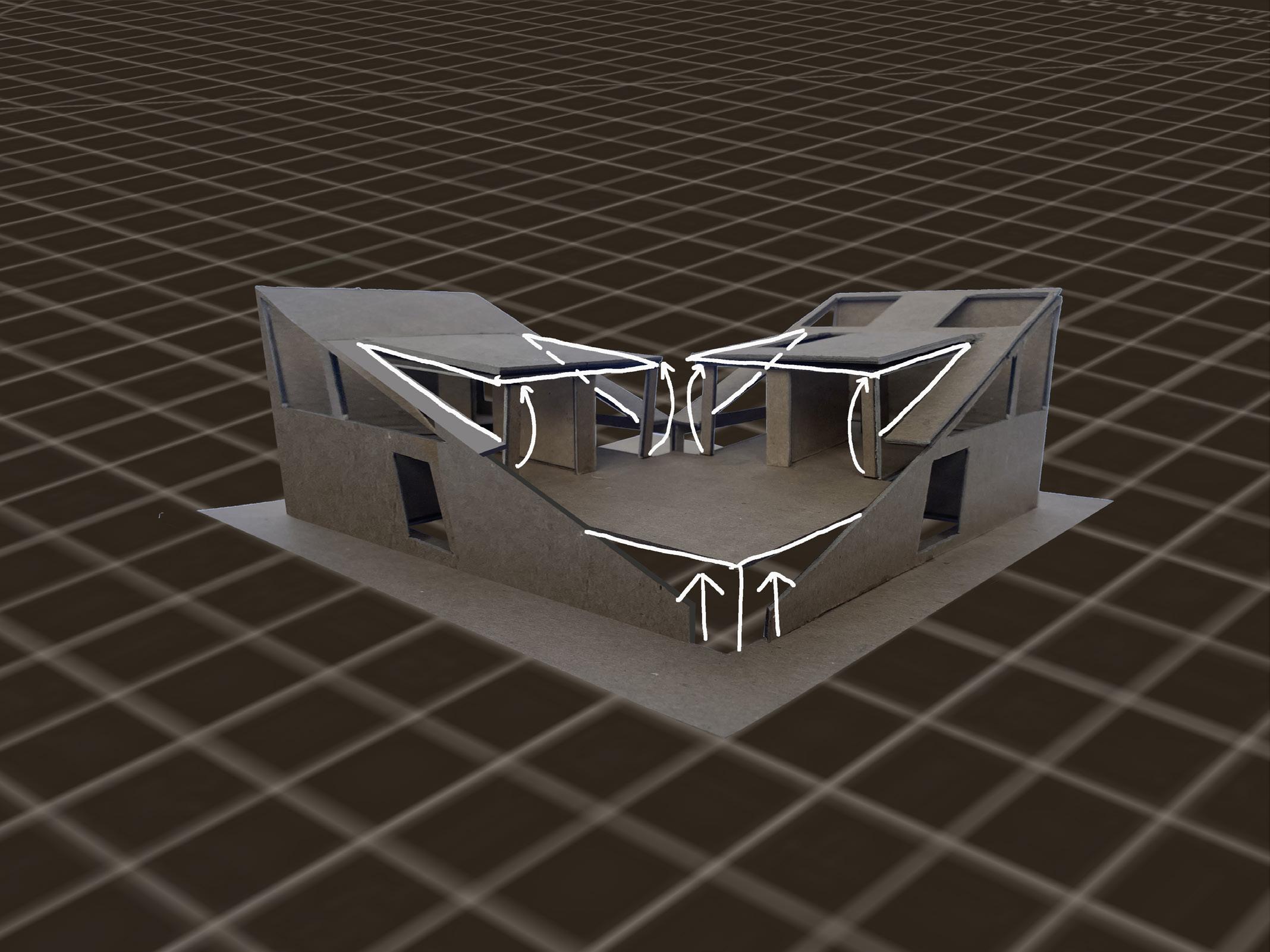
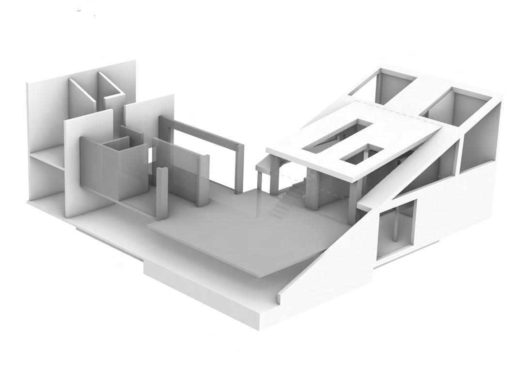
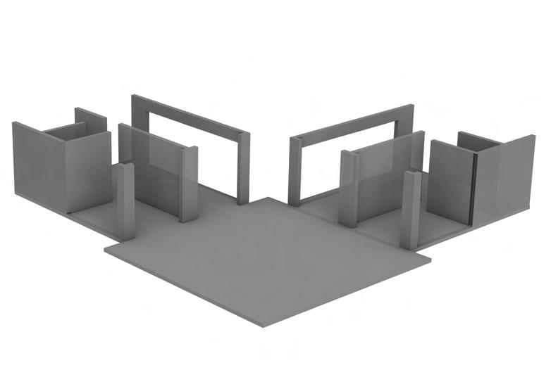
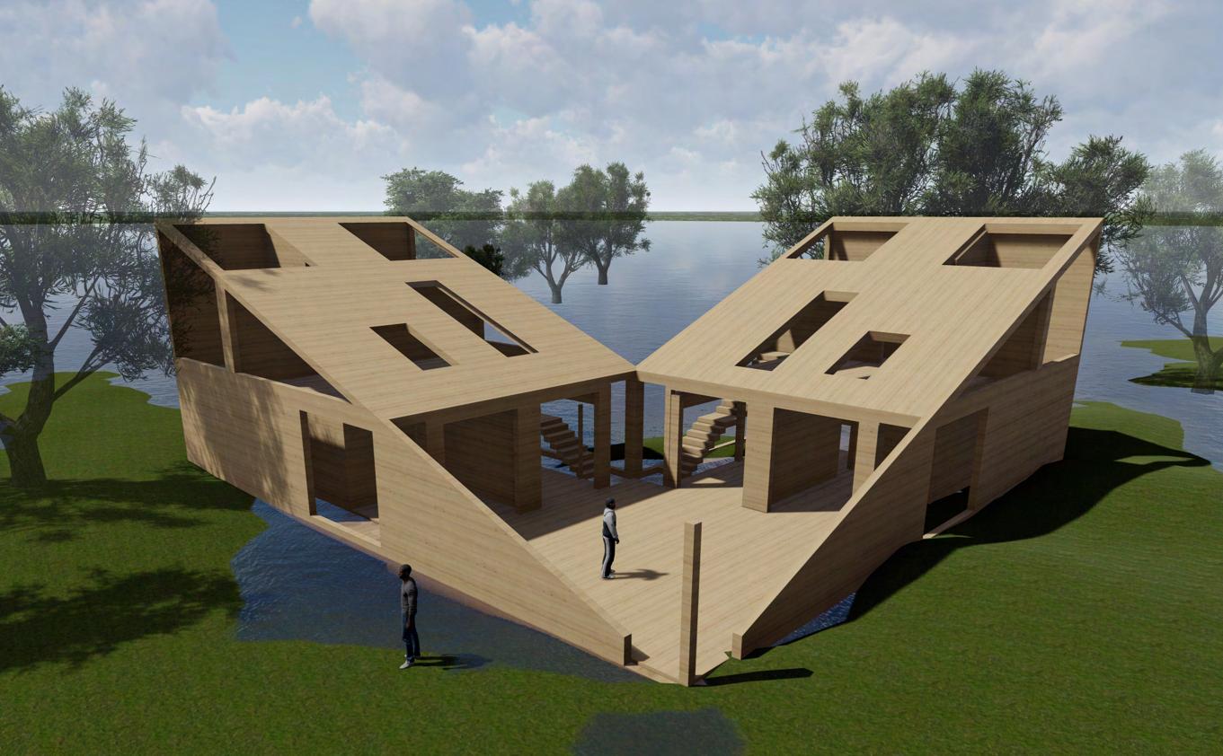
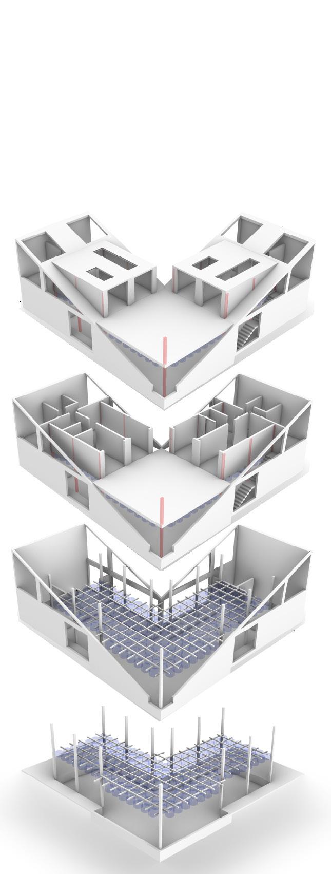
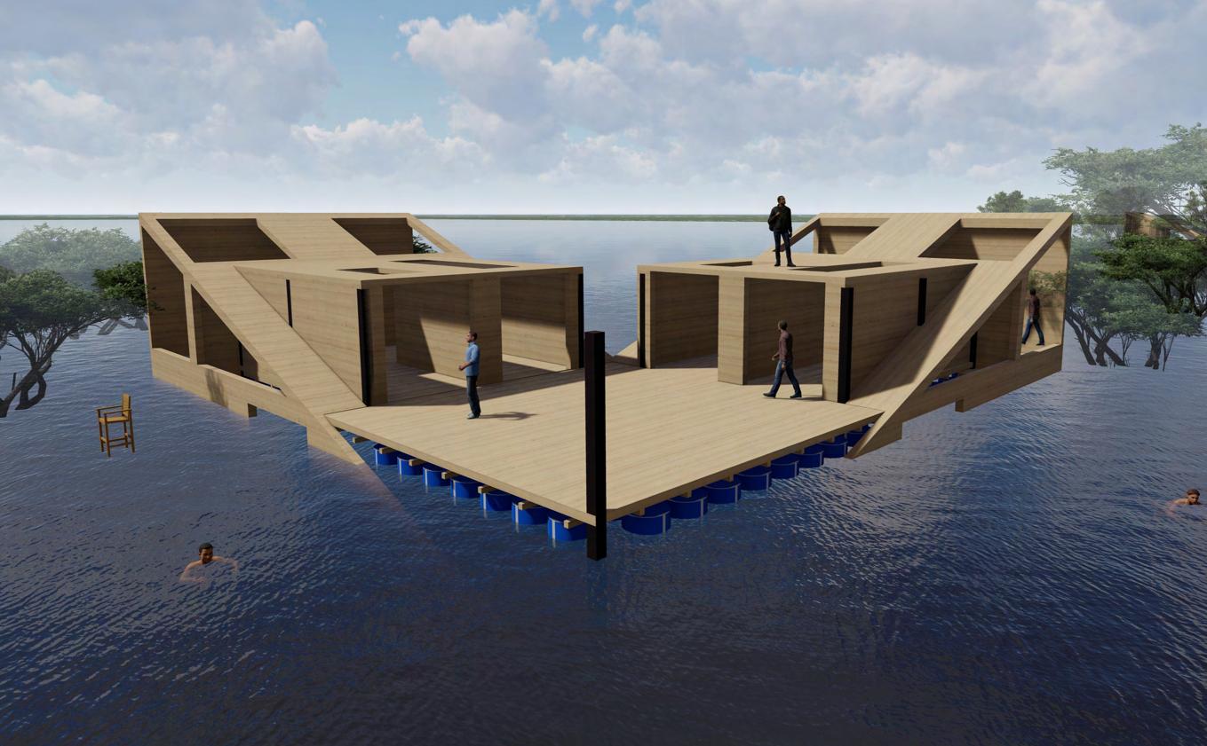
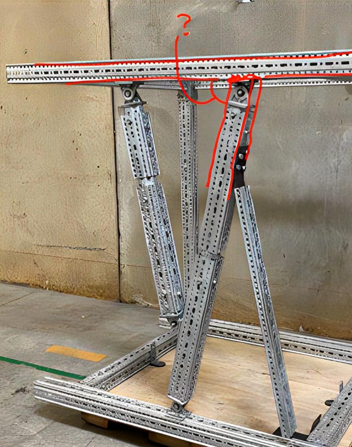
The proposed multi-family home of 1500 square feet is located in the Delta region of Mississippi, near the town of Mayersville with a population of approximately 450 people. Designed to withstand periodic flooding and irregular weather events, the building incorporates Amphibious Architecture and is constructed using mass timber. With its innovative design, the building transforms itself during floods, taking advantage of the floatation principle to allow the buoyant forces generated by the floodwaters to elevate a portion of the ground floor to the first floor, creating a new layout for the home. Additionally, the roof dormer opens up into an elevated walkway which are connected with each other connecting to a healthcare facility and flood rescue homes and support mobility during floods.
Roof dormer opens Platform moves up
Buoyant force
Buoyancy blocks


Guidance poles


BUOYANCY | M.Arch. Semester 2 | Spring 2021 27
Dry Time Physical model Flood Time Physical model 22 ft 22 ft 50ft 50ft 18 ft BUOYANCY | M.Arch. Semester 2 | Spring 2021
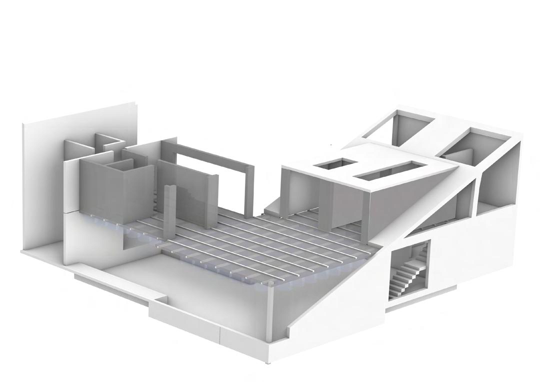
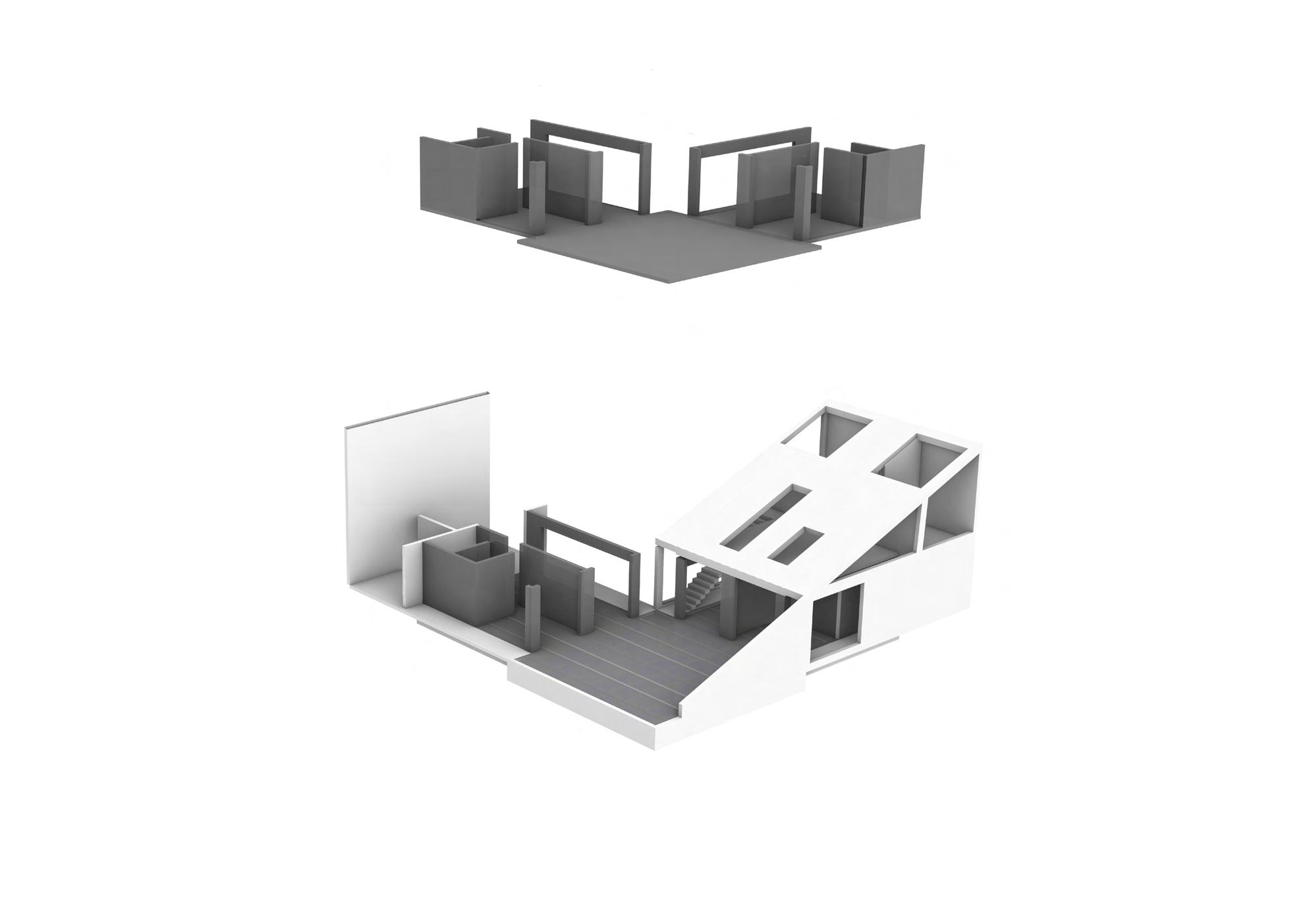
Flood Time Ground floor strcuture comes on first floor
M.Arch. Semester 2 | Spring 2021 | BUOYANCY 29
Roof
dormer opening up by the raised floor
DRY TIME
DRY TIME
Living

Kitchen
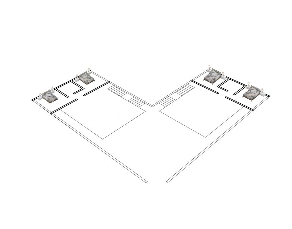
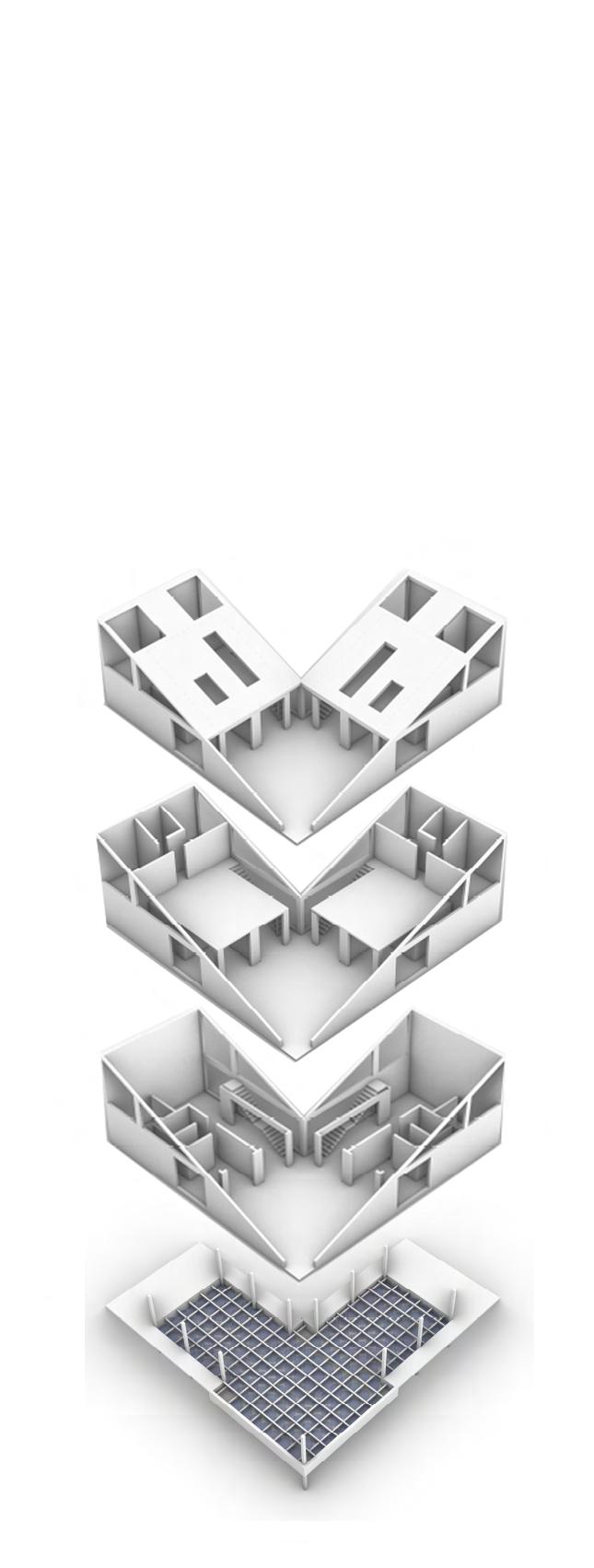
Dry Times Dry Time Exploded view
Seperate Living and Kitchen spaces which moves up due to buoyant force during Floods and 2 families share 1 living and Kitchen space They support and help each other BUOYANCY | M.Arch. Semester 2 | Spring 2021
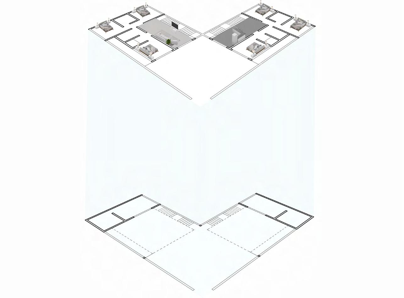
Flood Time Flood Time Exploded view Living Shared Living and Kitchen space between 2 families during Floods Kitchen M.Arch. Semester 2 | Spring 2021 | BUOYANCY 31
TIME
FLOOD
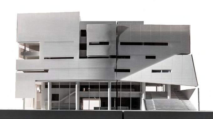
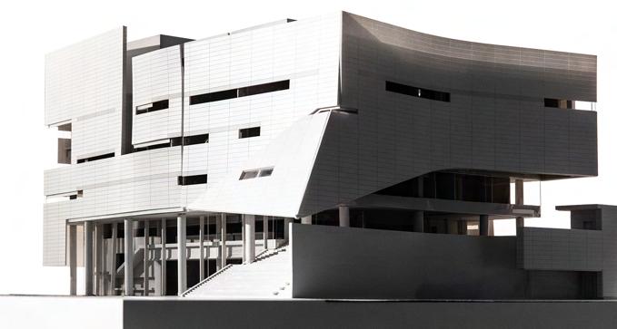
JUDY GENSHAFT HONORS COLLEGE
UNIVERSITY OF SOUTH FLORIDA
ARCHITECTURE FIRM

Morphosis , NY
LOCATION
Tampa ,Florida
CLIENT
University of South Florida
VISUALIZATIONS
Morphosis

MENTOR
Edmund Kwong
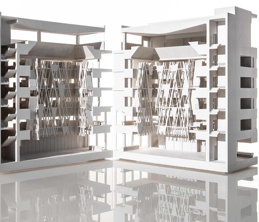
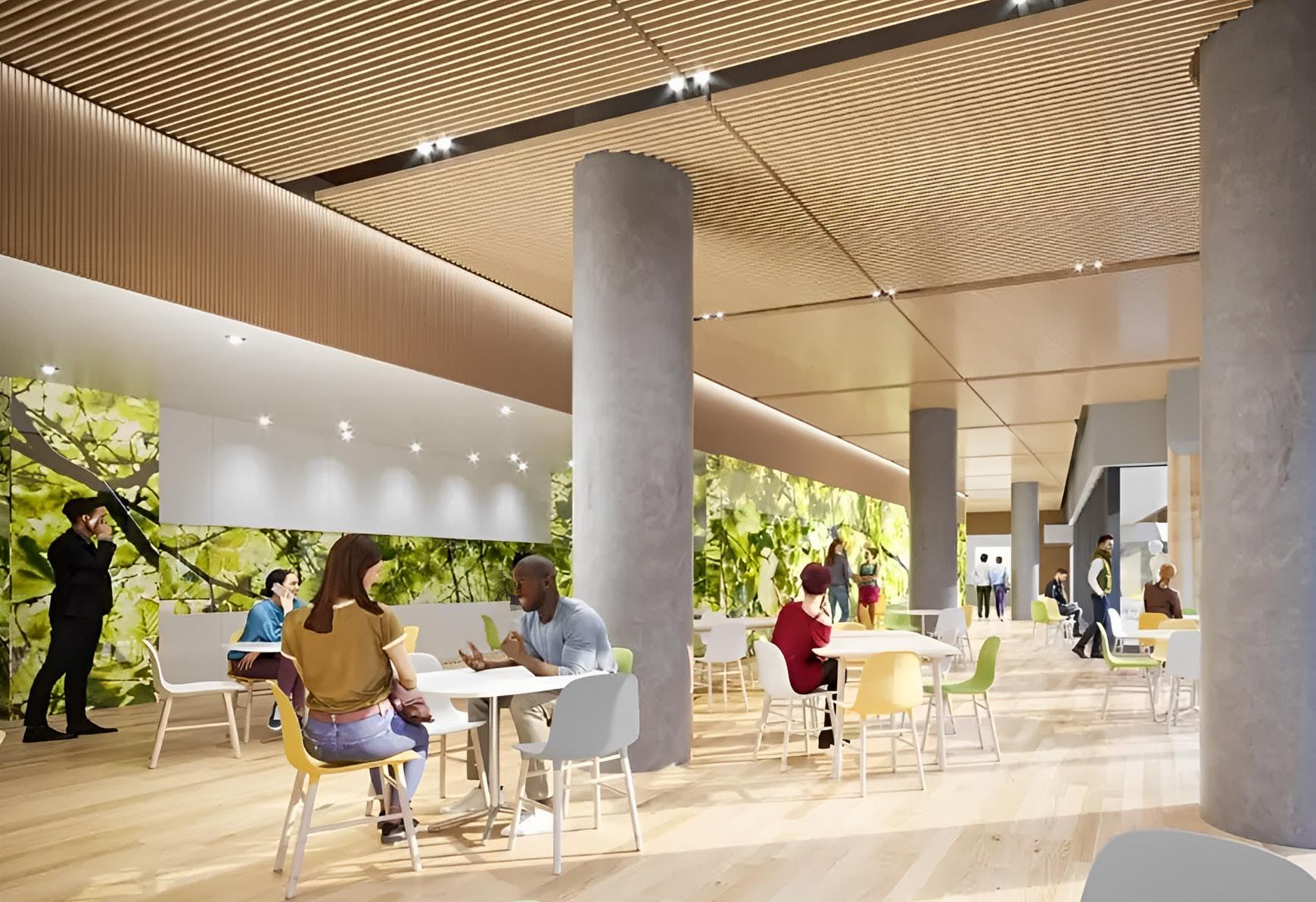
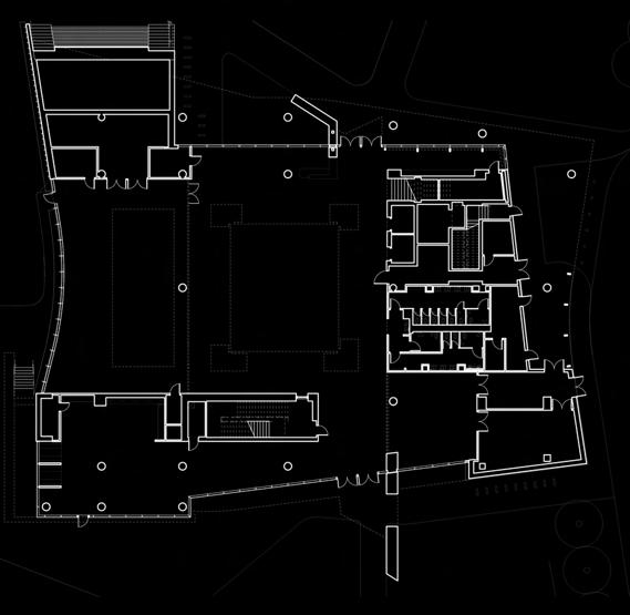
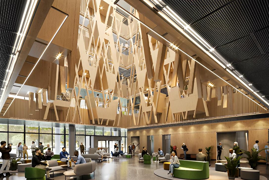
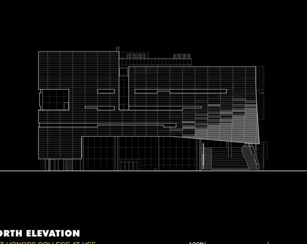
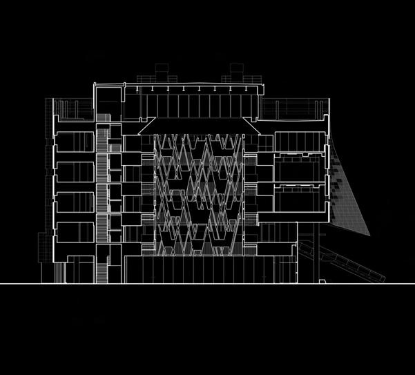
The Judy Genshaft building is an 86,845 square foot educational facility situated on 3.2 acres within the University of South Florida campus. The building is the first dedicated home for the Honors College, bringing together students, faculty, and administration from various departments across the university. The facility is designed to promote interdisciplinary collaboration and interaction, with classrooms, offices, and study spaces arranged around a central atrium and skylight. The building features a variety of amenities including classrooms, study areas, offices for faculty, advisors, administrators, and scholarship programs, event space, a computer lab, performance and creative spaces, a café, and an art and food studio. The café at the ground floor is expected to be a hub for campus life
Roles : Interior construction and designing , Graphic Wall designing.


JUDY GENSHAFT HONORS COLLEGE | Morphosis | Spring 2021

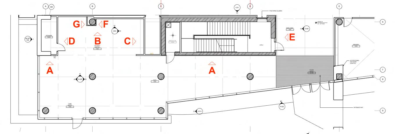
 Plan showing the
Graphic wall
Plan showing the
Graphic wall
JUDY GENSHAFT HONORS COLLEGE | Morphosis | Spring 2021
Graphic wall

Spring 2021 | Morphosis | JUDY GENSHAFT HONORS COLLEGE 35
3- Dimensional structure
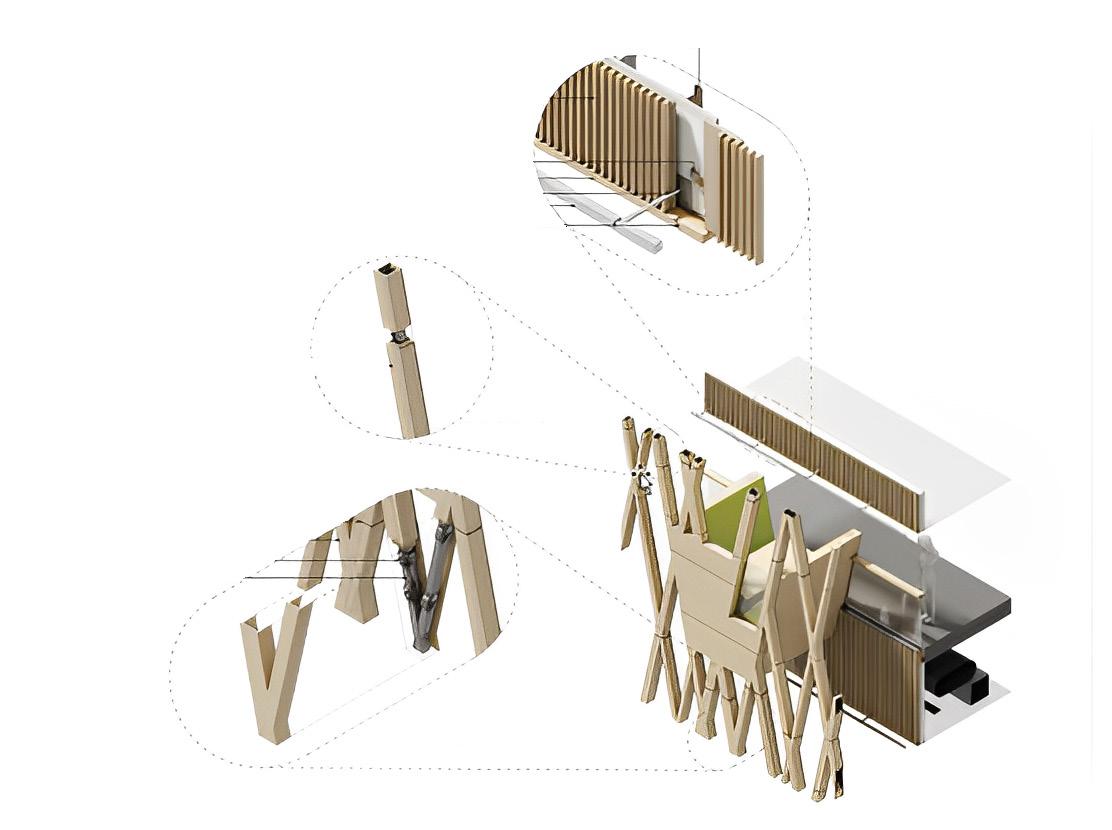
 WOOD PANEL DETAIL
WOOD LATTICE ASSEMBLY
SLIP JOINT DETAIL
Interior view of Honors college
WOOD PANEL DETAIL
WOOD LATTICE ASSEMBLY
SLIP JOINT DETAIL
Interior view of Honors college
JUDY GENSHAFT HONORS COLLEGE | Morphosis | Spring 2021
Interior Structure detail
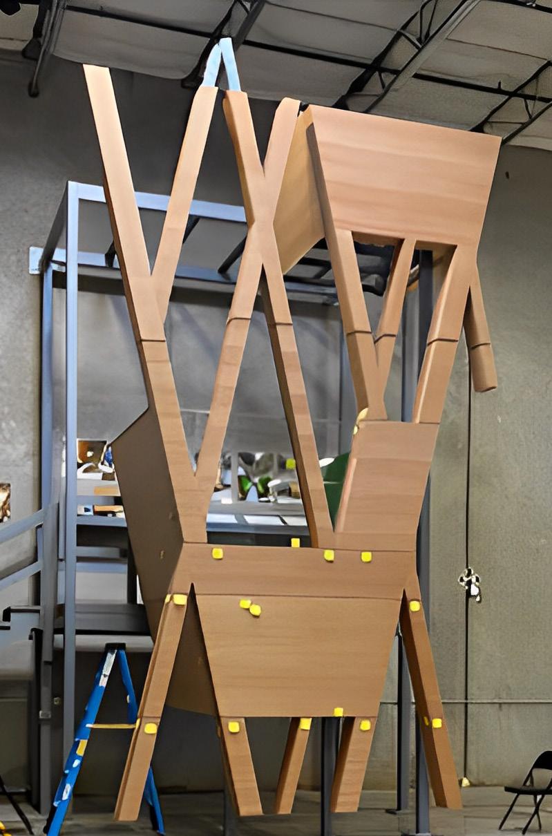
 Wood cladding Mock-up model
Spring 2021 | Morphosis | JUDY GENSHAFT HONORS COLLEGE 37
Structural Mock-up model
SABARMATI HIGH SPEED RAIL TERMINAL CIRCULATION NETWORK SHAPES TERMINAL
COLLEGE
Institute of Architecture, Nirma University
LOCATION


Ahmedabad , India
INSTRUCTOR
Prof. Viren Shah | Falguni Goghari | Sujan Umaraniya
MODULE


Undergraduate Design Thesis


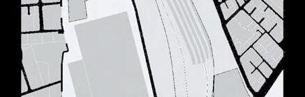
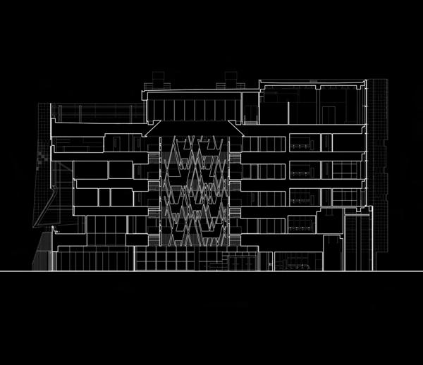
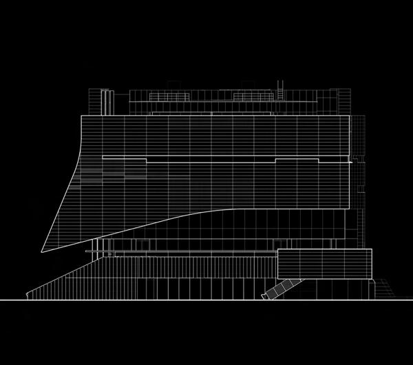
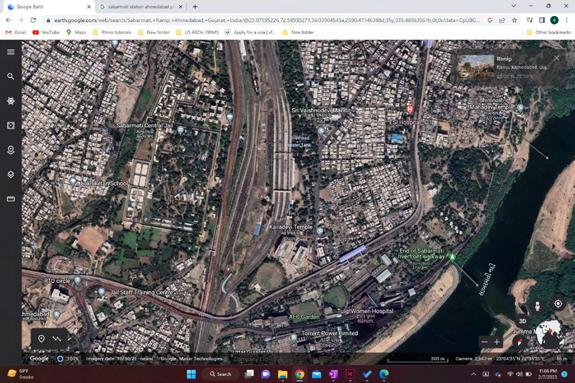
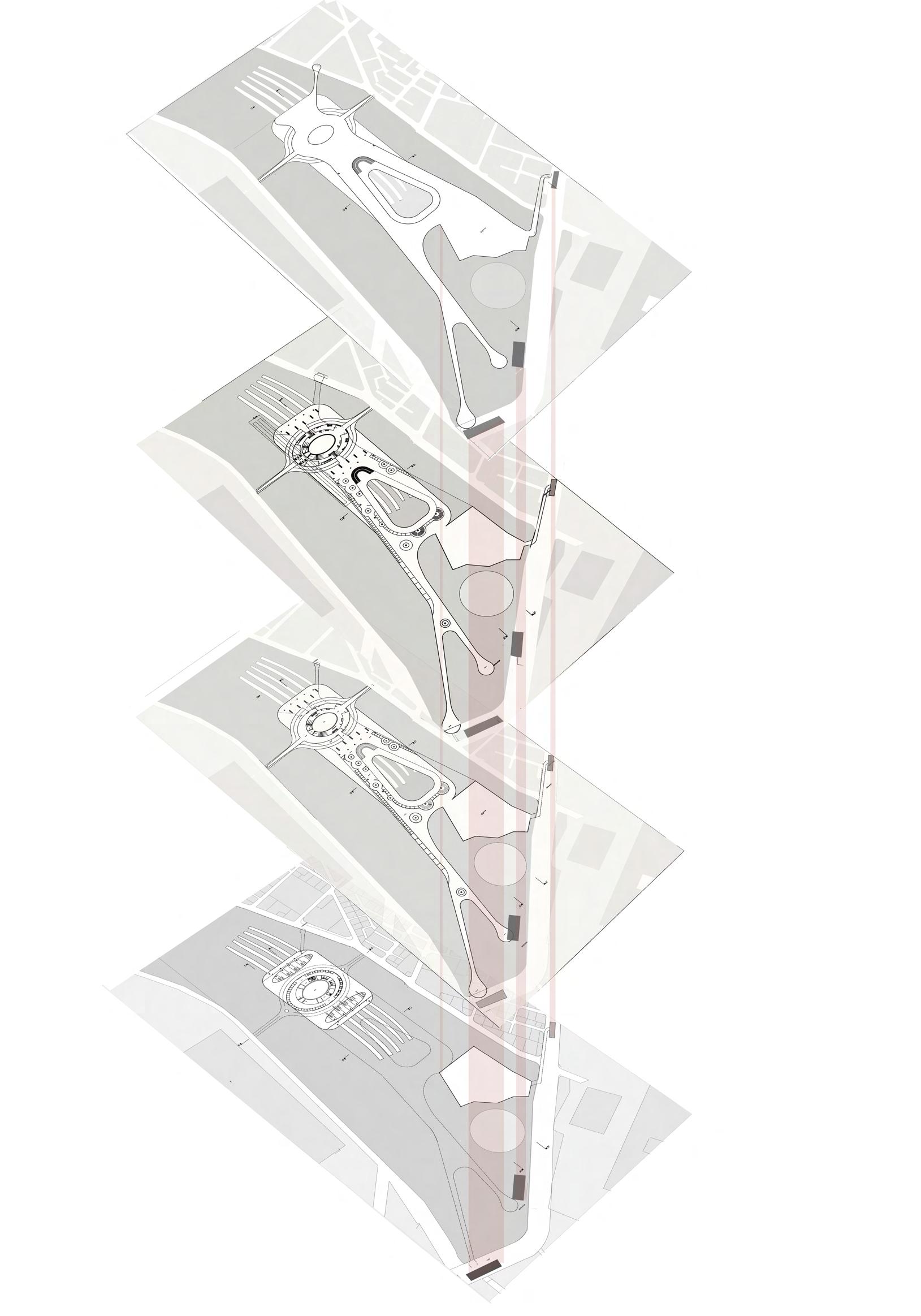
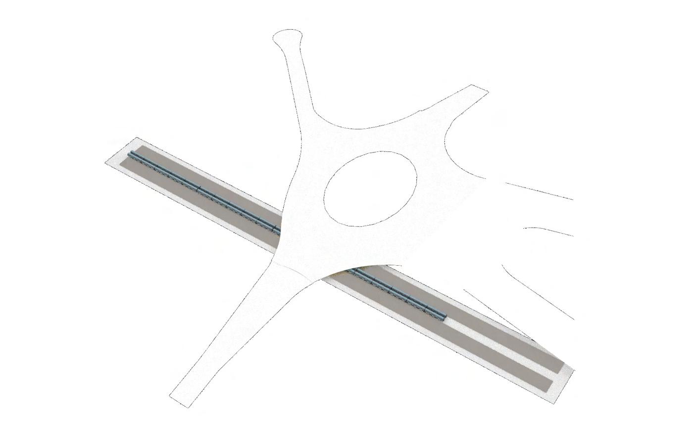
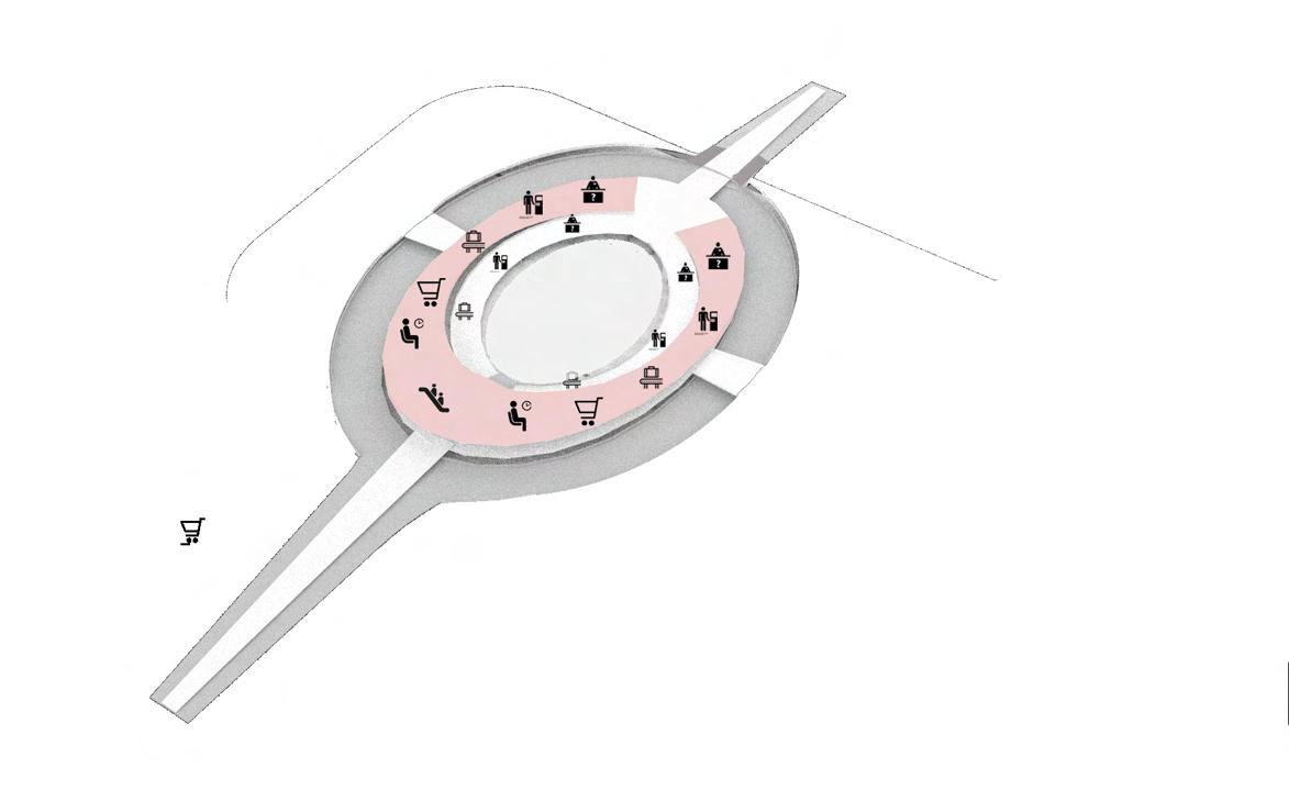
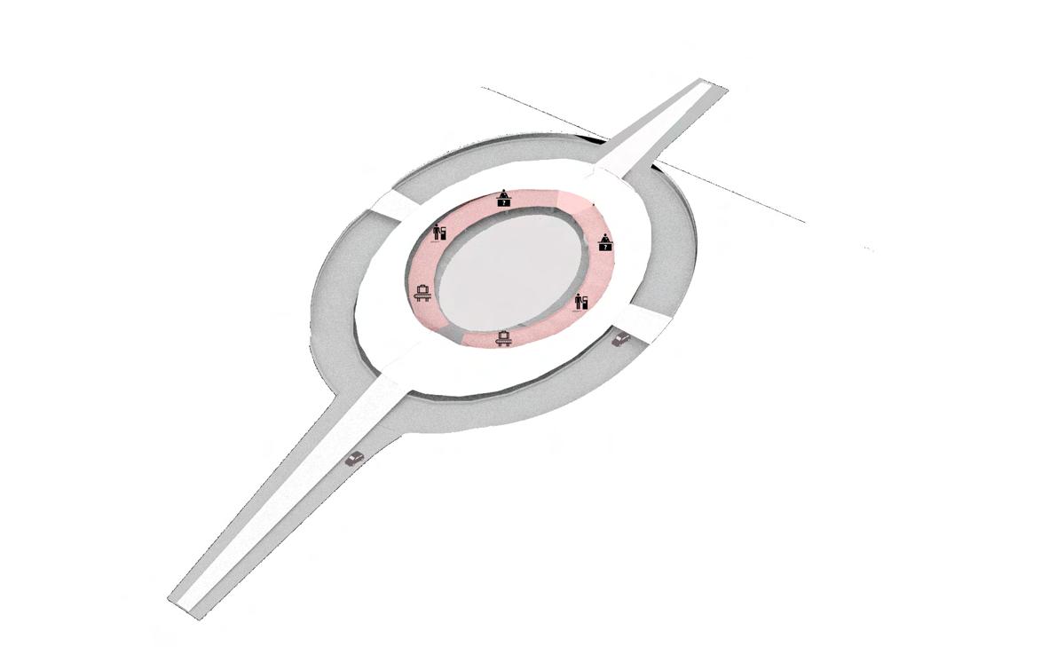
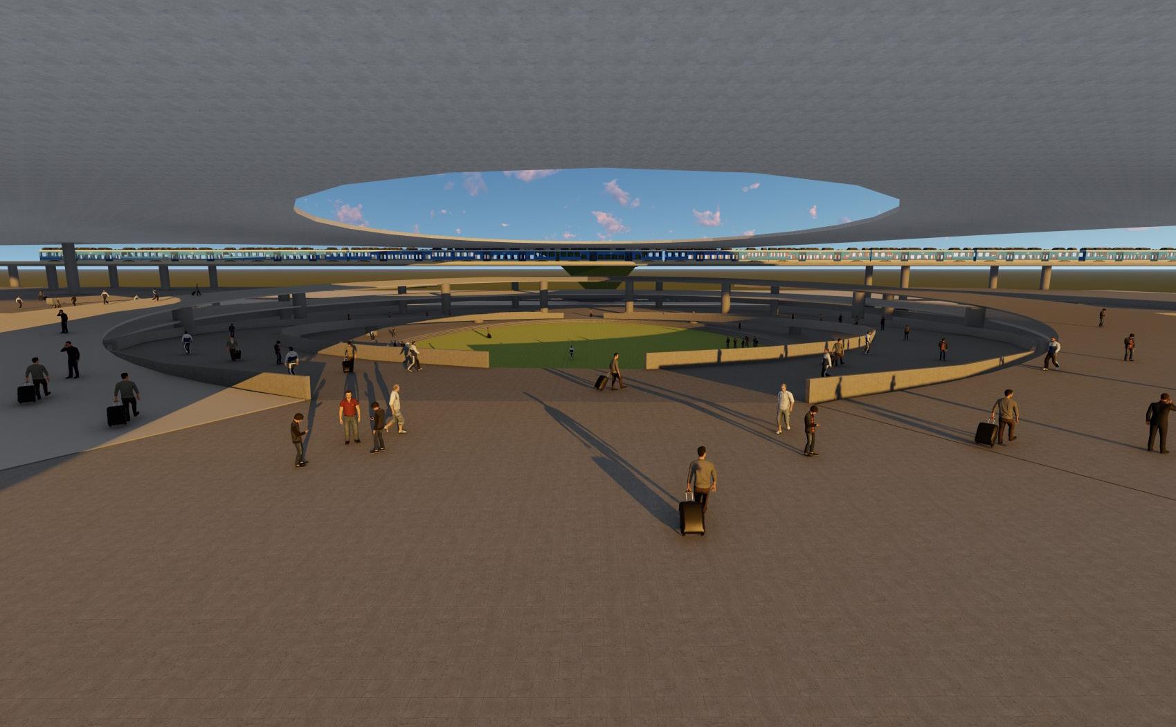
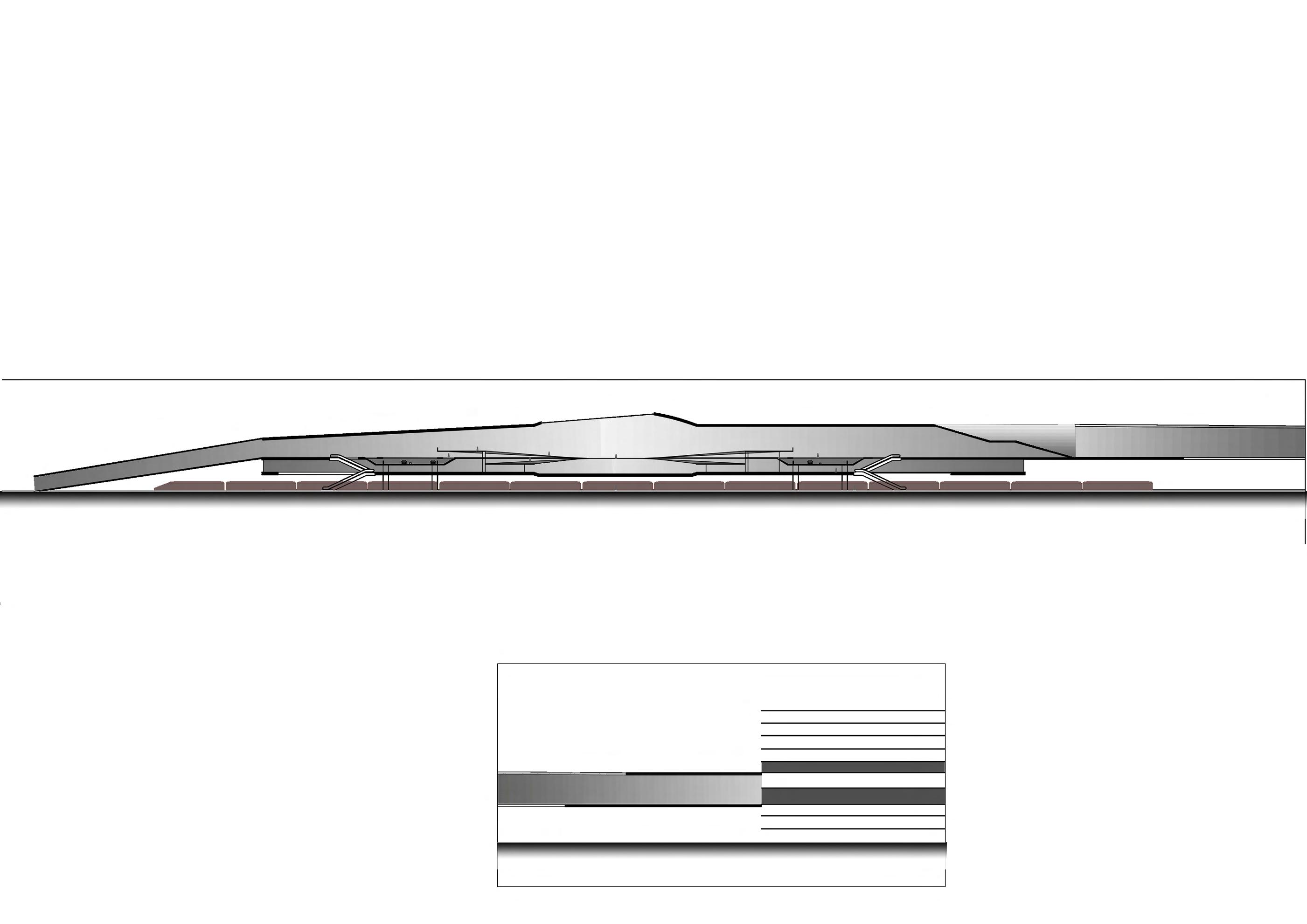
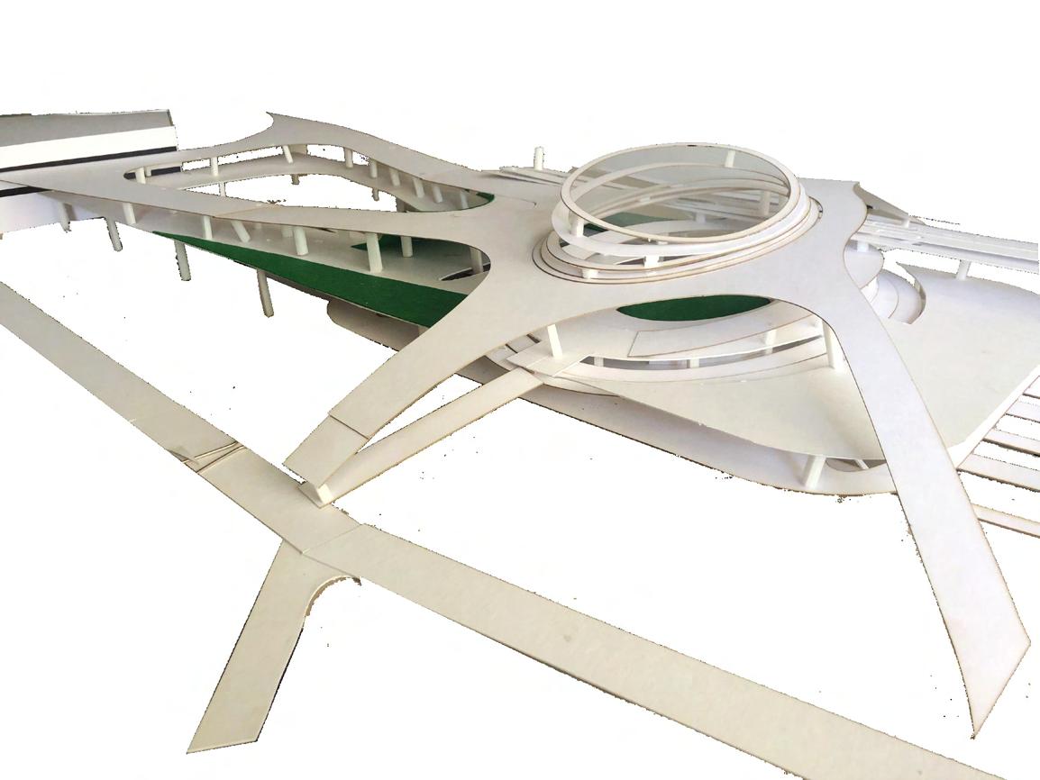
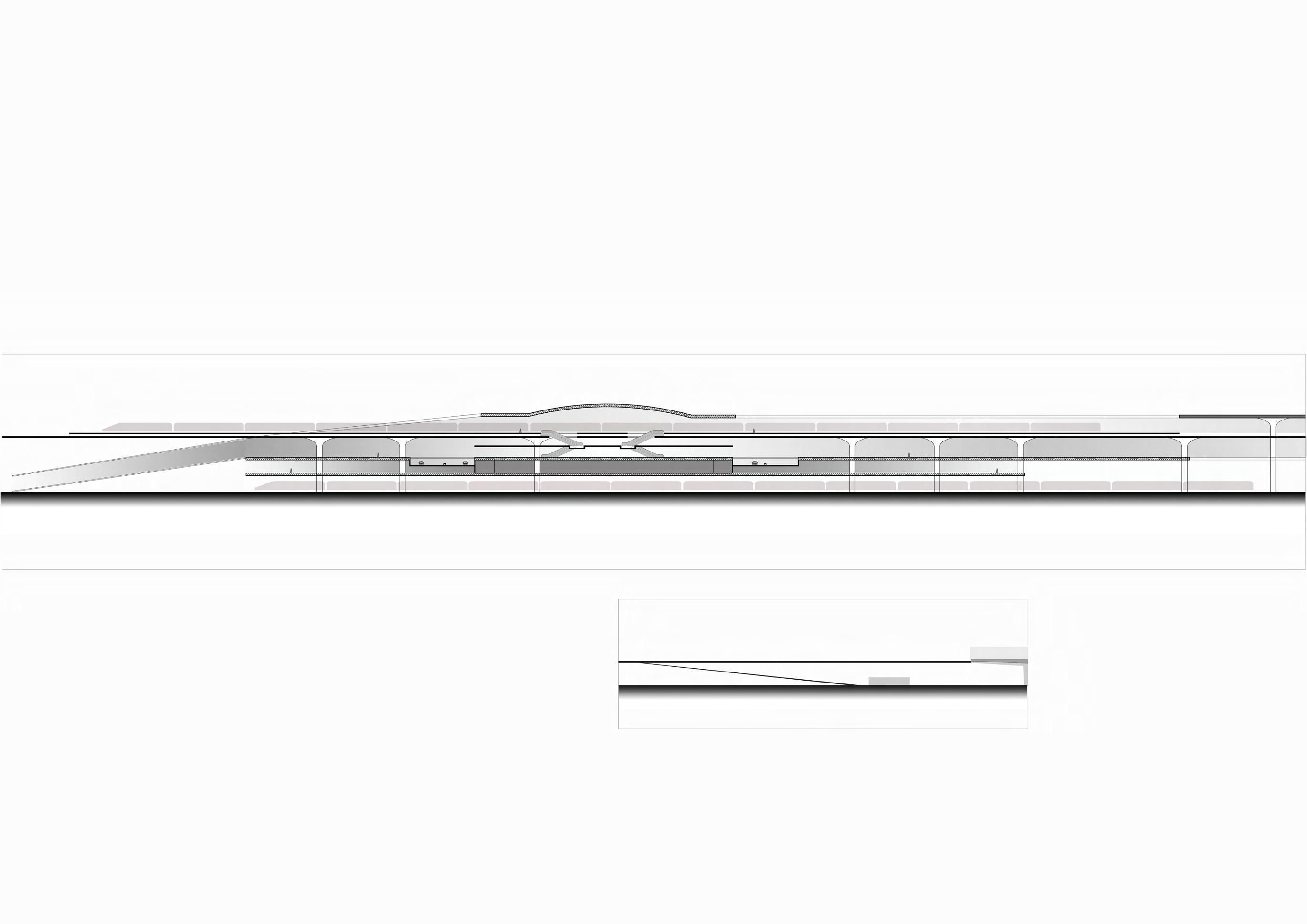
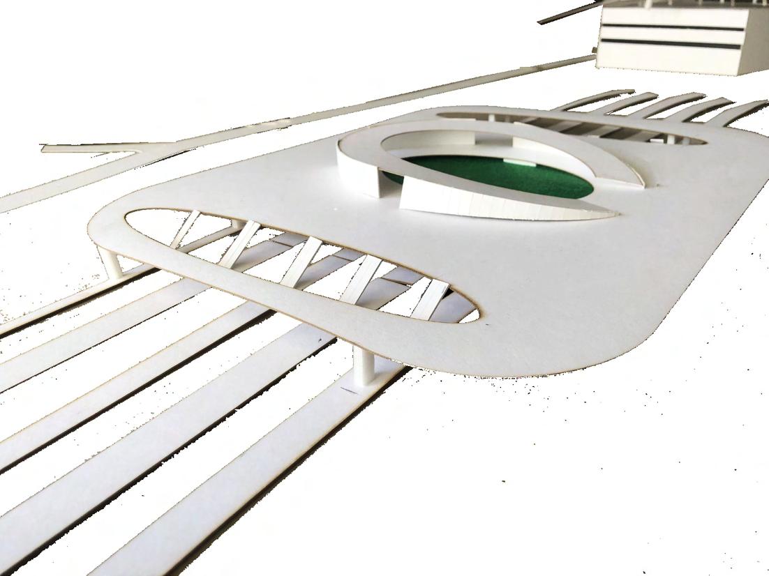
The program is focused on the redevelopment of the Sabarmati conventional station and the development of the upcoming High-Speed Rail (HSR) terminal. The terminal is designed as a unified facility that will serve both conventional and high-speed rail platforms. It will function as a transportation hub, providing access to conventional rail, high-speed rail, metro, local buses, and taxis. The station’s design incorporates materials such as glass, transparent polycarbonate elements, perforated steel, and concrete to create a modern and airy atmosphere. These materials give the station a contemporary expression while also lending a sense of lightness to its overall design.

METRO BRTS HSR HUB ENTRY/EXIT RESIDENTIAL BRTS METRO GIVING A DIMENSION FOR CIRCULATION AND PULIC SQUARE. CURVING THE EDGES FOR SMOOTH FLOW. CIRCULATION NETWORK SHAPES THE BUILDING Due to increasing population and traffic and people using more of private transport , it is expected that due to the heavy traffic and time problem people will start relying more on pulic transport . meeting of all 4 kinds of public transport at one place. connecting the station tot the public transport is the most important part circulation is a very major part of a railway station. 1. shorter distance 2. walking on interesting pathways 3.destination 4.connectivity CIRCULATION BRTS AUTO TAXI CONNECTIONS TO TRANSPORT AND PLANNING, NIRMA UNIVERSITY METRO BRTS HSR HUB ENTRY/EXIT RESIDENTIAL BRTS METRO CONNECTING POINTS CREATING PATHWAYS ELIMINATING UNWANTED PATHS. GIVING A DIMENSION FOR CIRCULATION AND PULIC SQUARE. CURVING THE EDGES FOR SMOOTH FLOW. one staCIRCULATION RAILWAY BUS BRTS AUTO TAXI PRIVATE VEHICLE METRO HSR TERMINAL STATION AREAPUBLIC PLAZA CONNECTIONS TO TRANSPORT
Metro station Bus station Bus station HSR Hub Hotel SABARMATI RAIL TERMINAL | B.Arch. Semester 9 | Fall 2020 39
Roof Cafe , organic farming , solar panels , cycle stands
Third High speed rail platform and concourse
Second Public space entry to the terminal Atrium
First conventional Rail concourse area
Ground conventional Rail platform
High Speed Rail platform

Conventional platform
Circulation Path shapes the Terminal
Atrium (waiting area)
ROOF - Green connector which unifies different modes of transport
Transport Hub - concourse area , hotel , shops , parking
Bus station
Metro station
Metro
41
Local Bus station
station
conventional Rail concourse ramp leading down to Platforms
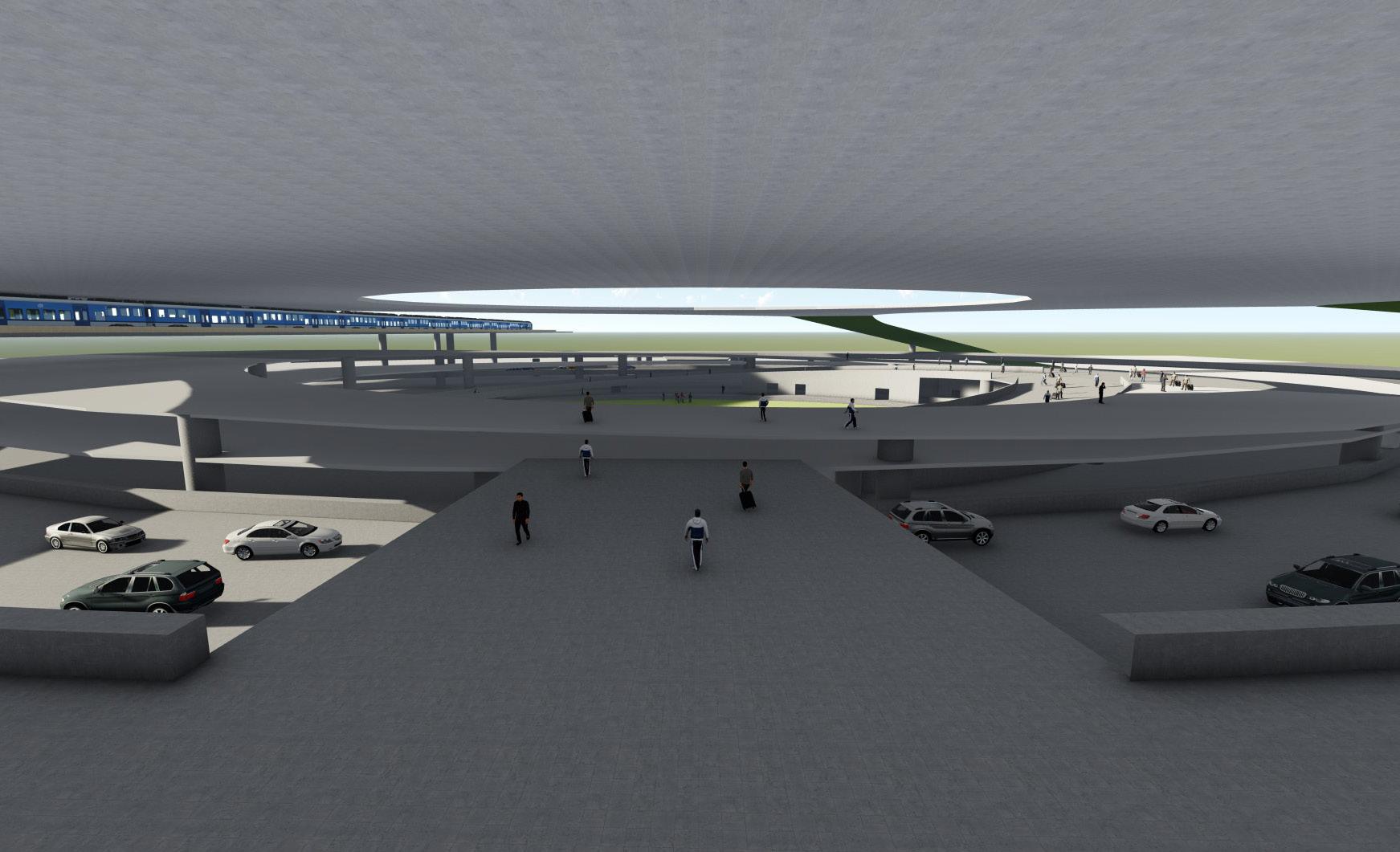
vehicular circulation track (parking , drop off , pickup)
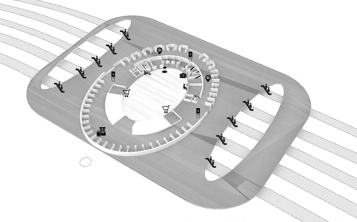
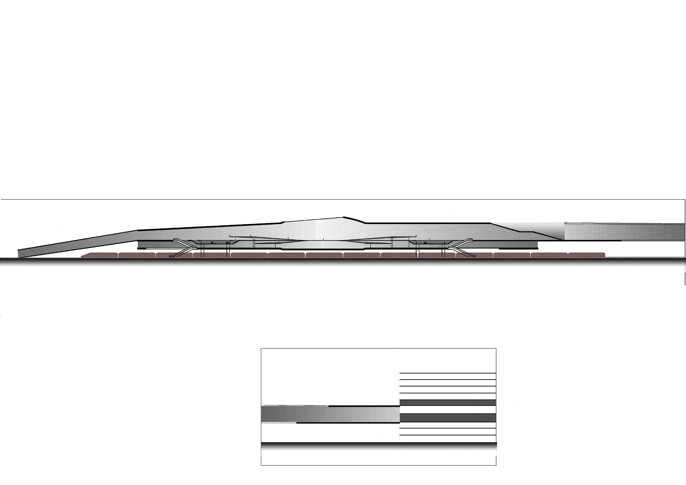
Elliptical form of the Terminal allows for a simple and straightforward operational mode: it provides good circulation conditions to vehicles, and it offers travellers the most direct route to waiting rooms and platforms.
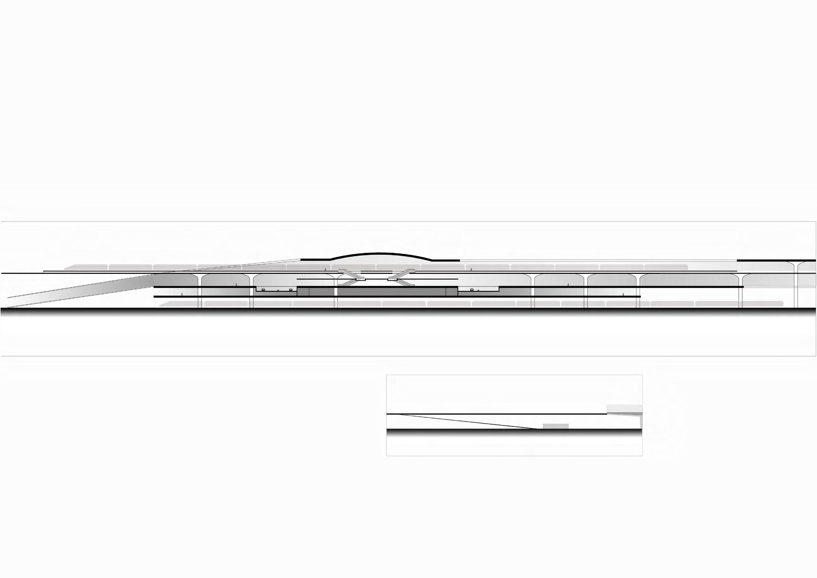
Exploded view SABARMATI RAIL TERMINAL | B.Arch. Semester 9 | Fall 2020
High speed rail concourse
43
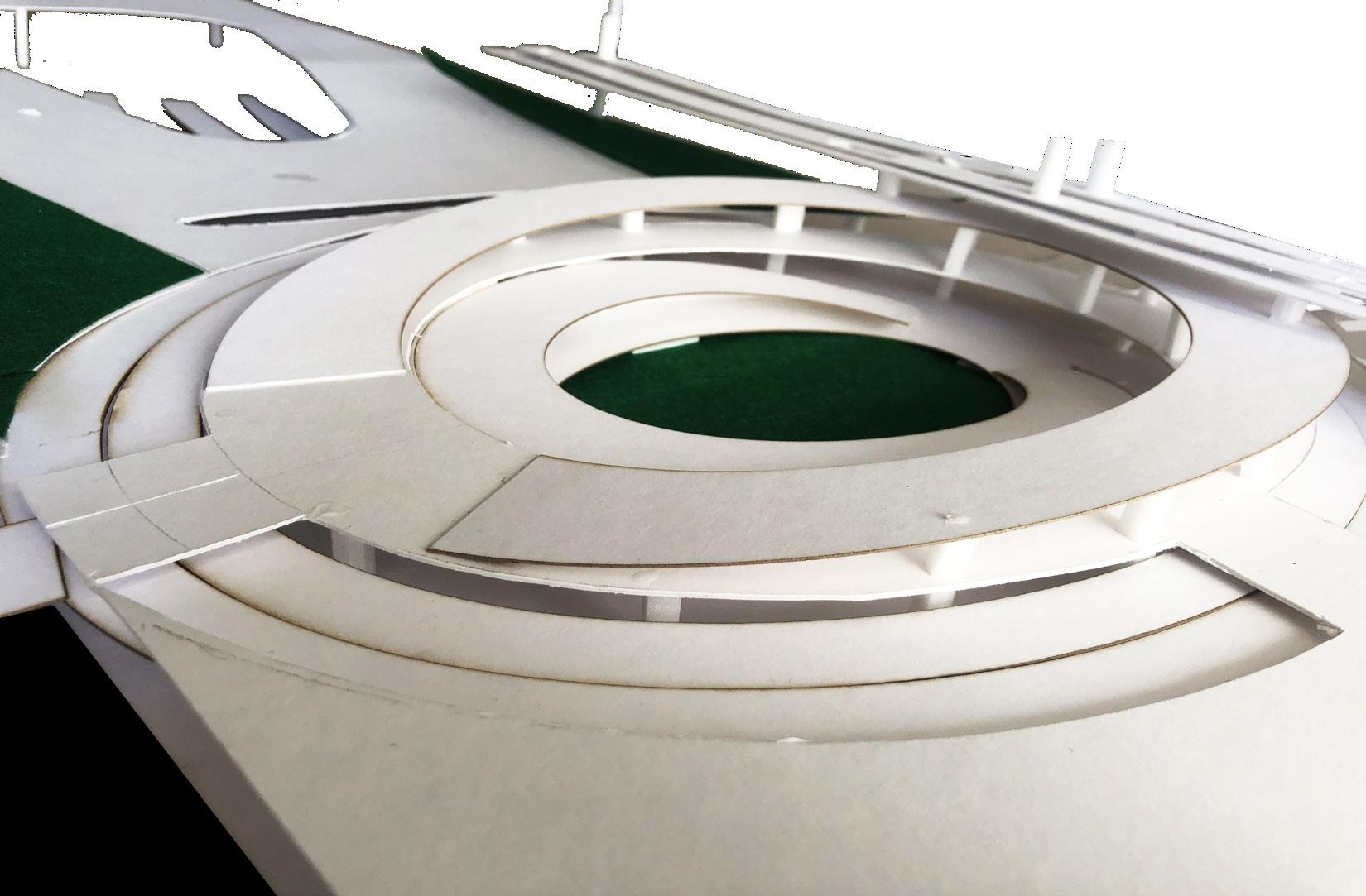
Physical
Concourse circulation
model
Physical model

Conventional Concourse view 45
Physical model Physical model
SOPE CREEK ELEMENTARY SCHOOL INSTITUTIONAL
ARCHITECTURE FIRM


 J.W. Robinson & Associates


LOCATION
Marietta, GA
CLIENT Cobb County School District
MENTOR
Ar. Chela Bourne
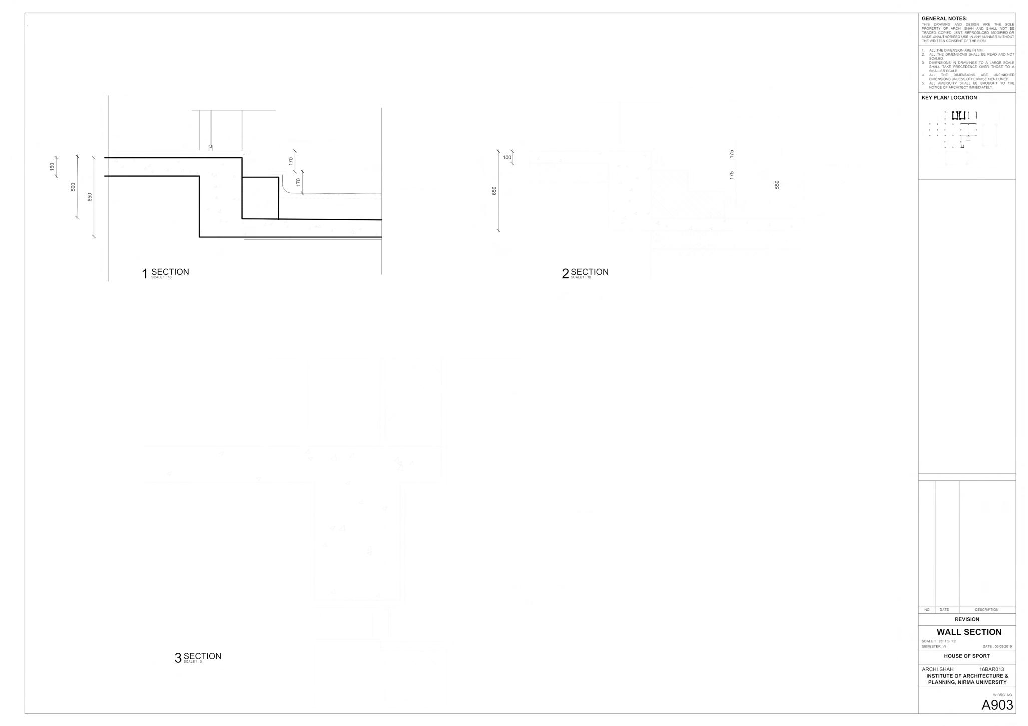
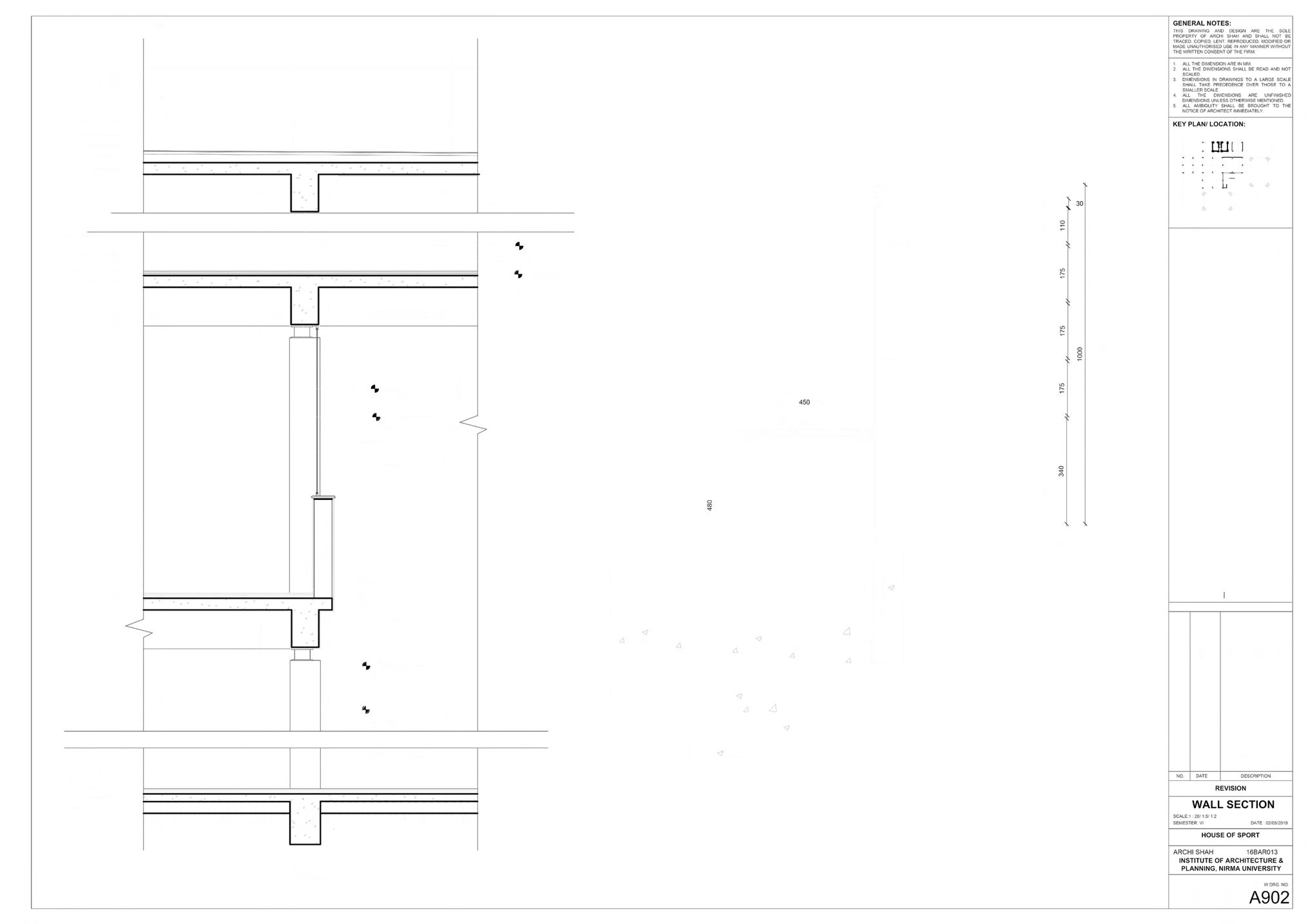
The proposed gymnasium building is an addition to the existing school and will serve as a space for various sports activities, including basketball, yoga, aerobics, and more. The gymnasium will also function as a multipurpose hall for various events and activities. The building features brick cladding on concrete, which is in keeping with the design and style of the other buildings within the school. The current school building measures 118,318 square feet, while the new gymnasium will add an additional 12,017 square feet of space.
Roles: DD , CD , Renderings , Submittals


UNTAGGED STUD PARTITIONS ARE W030 (TYP).
UNTAGGED MASONRY PARTITIONS ARE W180 (TYP).
DIMENSIONS ARE TO FACE OF STUD OR MASONRY UNO.
GWB & STUD PARTITION
CMU PARTITION
1 HR RATING
2 HR RATING
SOPE CREEK ELEMENTARY SCHOOL | J.W.R | Summer 2022 DN UP TV TV TV TV FD RD
13 A702 4 A403 1 UNIT A1.1 222 H
DINING PATIO Client: Copyright (c) 2021 Praxis3, All reports, plans, specifications, and instruments prepared by reserved rights, including copyright This drawing may not be reproduced Praxis3. It is to be returned upon drawings.
Architect:
11.18.2290% TRUE NORTH 1/16" = 1'-0" A101 2 Second Floor Plan
FUTURE
Associate
RevDateComments 09.23.2022LDP
Floor Plan Building Elevation SOPE CREEK ELEMENTARY SCHOOL | J.W.R | Summer 2022
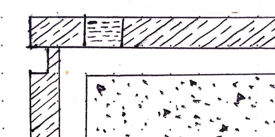
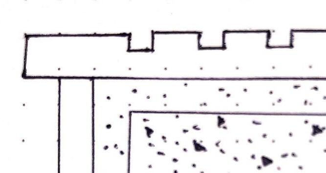
Window Head Detail Wall Section Detail Window Jamb Detail Parapet Detail Summer 2022 | J.W.R | SOPE CREEK ELEMENTARY SCHOOL 49
COLLEGE Georgia Institute of Technology
LOCATION
Bellwood Quarry , Atlanta , GA
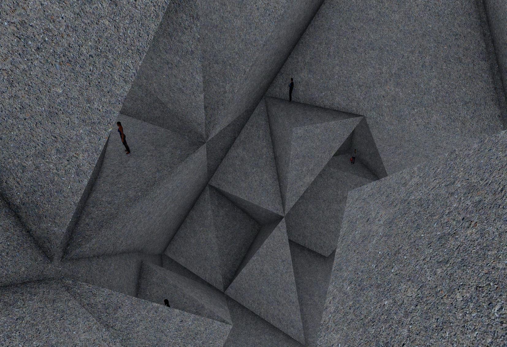
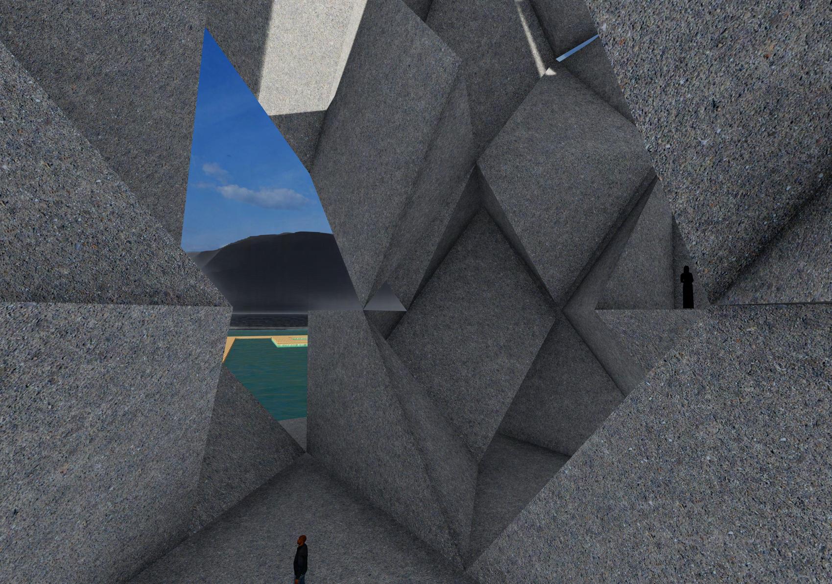
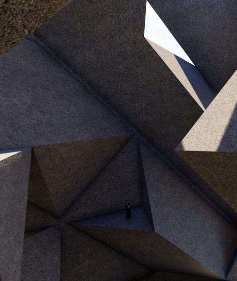
EARTH RECORDER
INSTRUCTOR Prof. Michael Gamble
MODULE Graduate Advance Studio
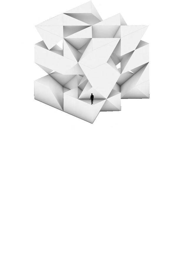
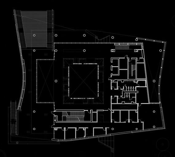
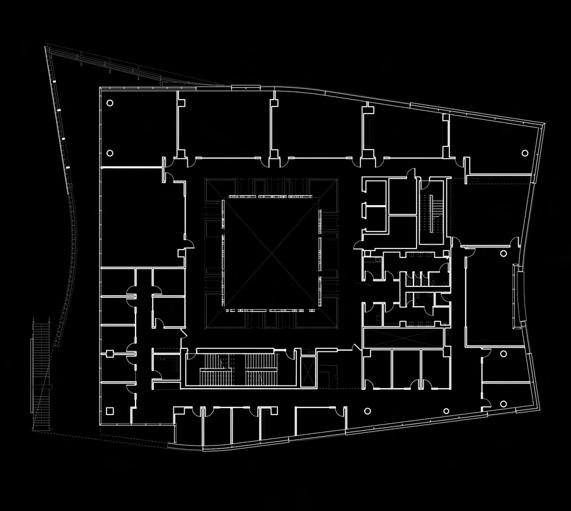
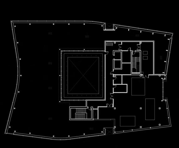
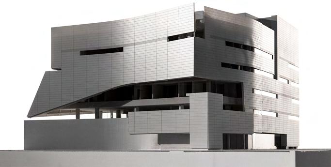
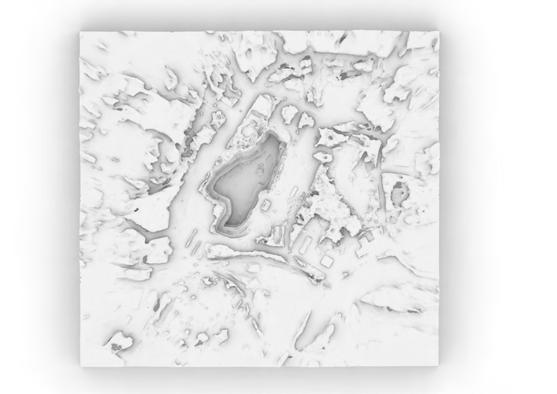
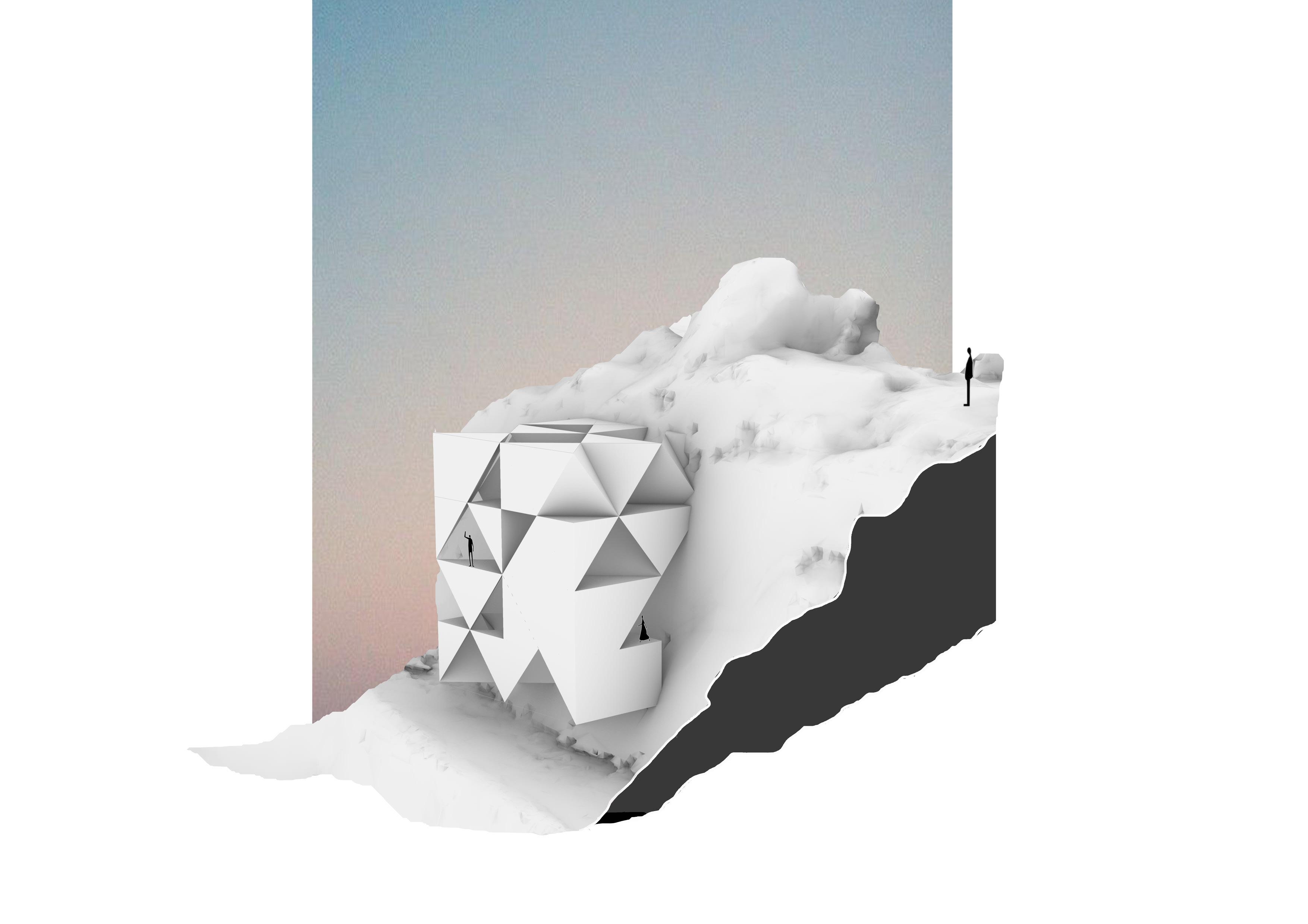
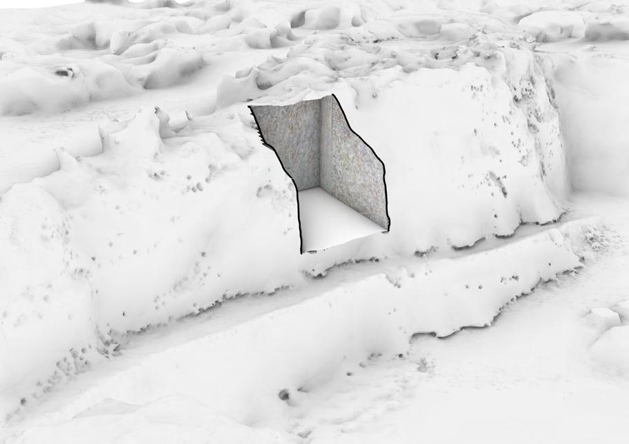
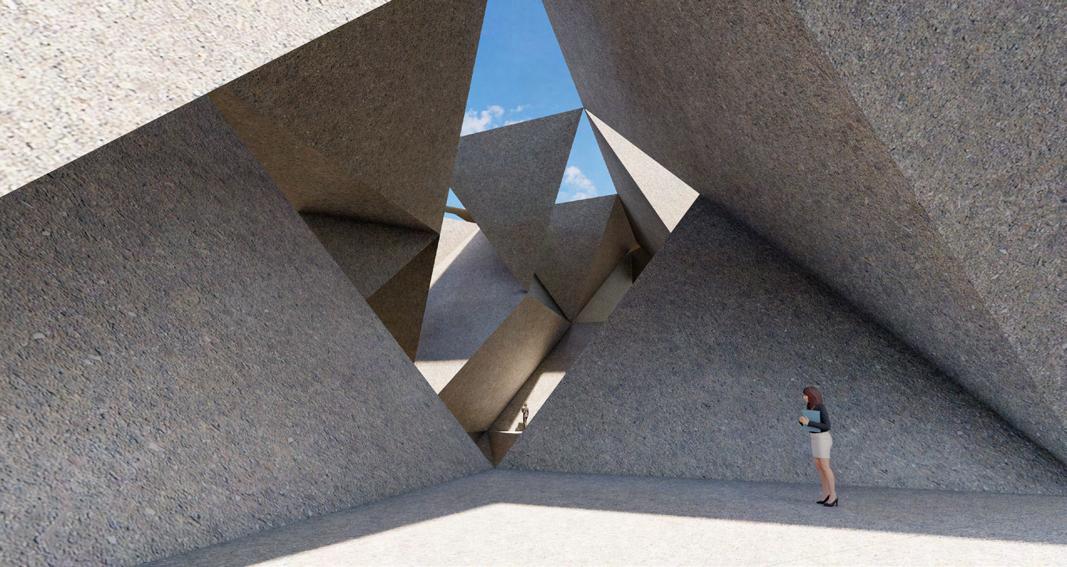
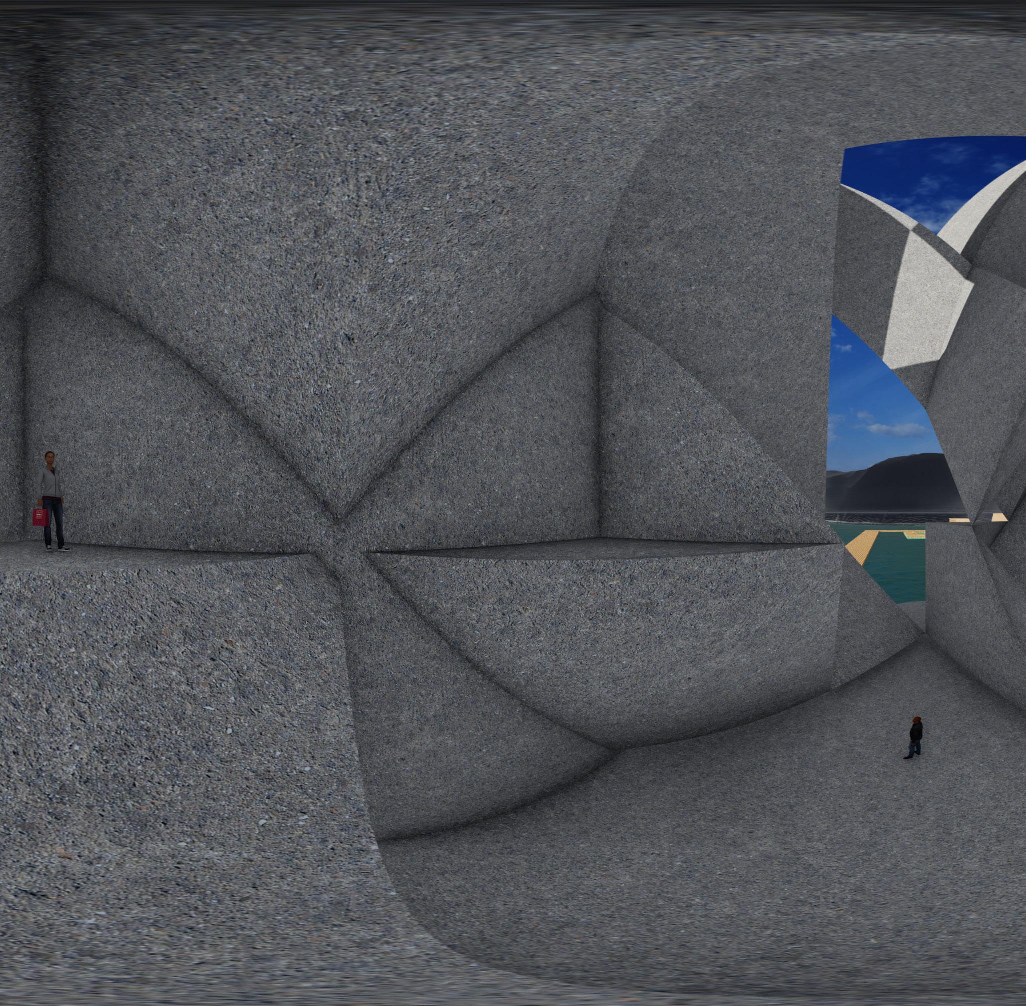
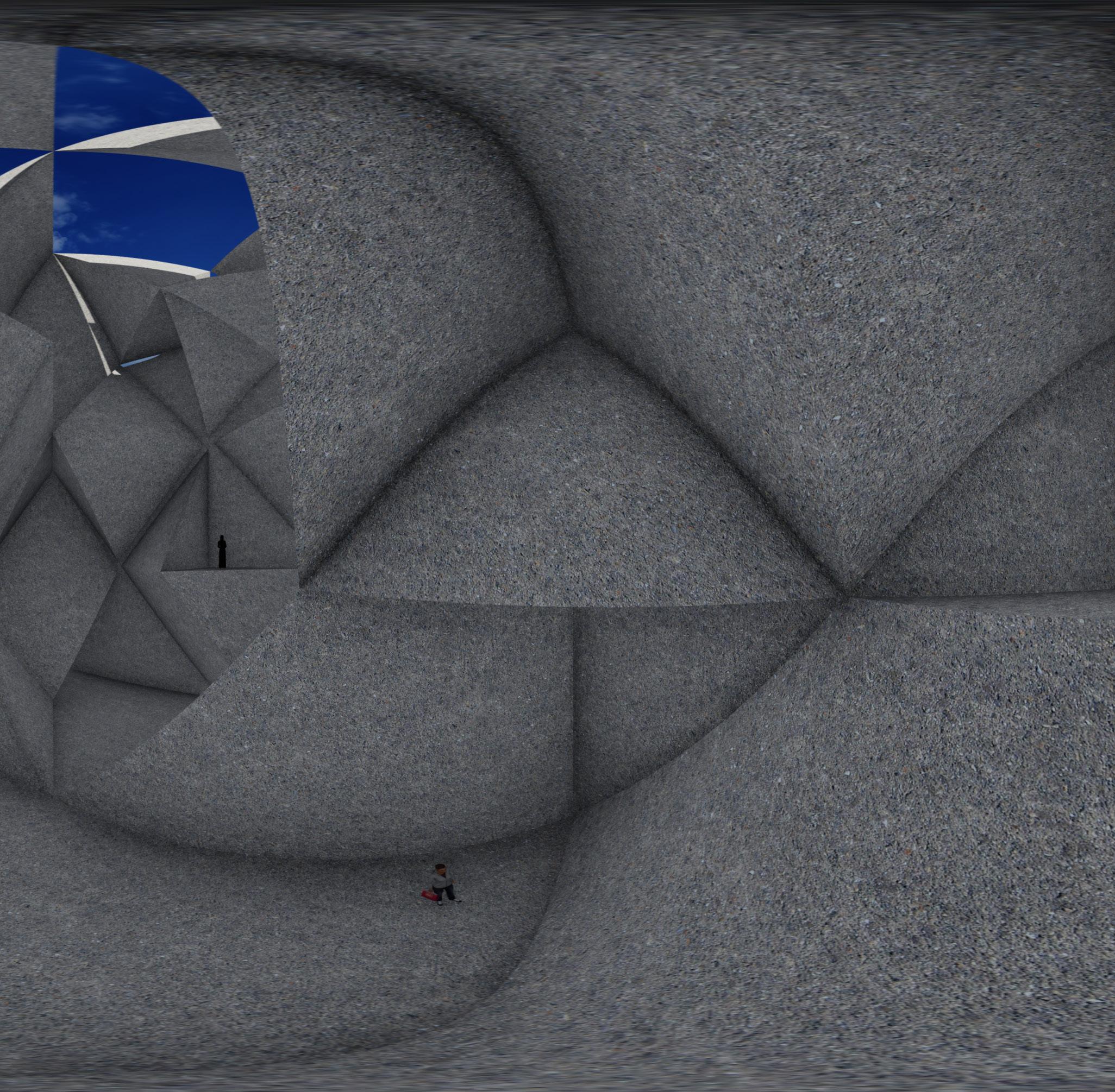
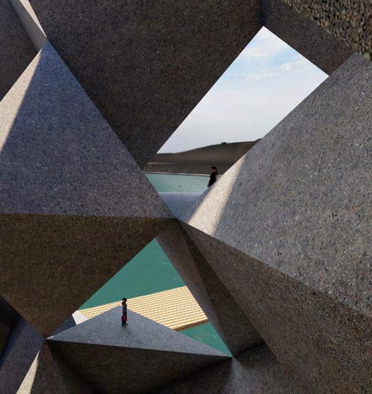
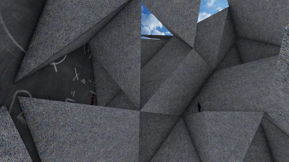
The Museum of Indian Traditions is a place where visitors can immerse themselves in Indian culture, including festivals, languages, music, dance, and cuisine. The goal of the collectionis to maintain and pass on the authentic history and cultural heritage of India, spanning past, present, and future. The museum is located in a hilly area with an interesting topography.The Bellwood Quarry is a 100-year-old depression in the landscape located near the Beltline in northwest Atlanta. It was previously used as a granite extraction site and a prison labor camp. The proposed building will be constructed by carving out granite.Location consists of many hills which forms an interesting topography the area.

EARTH | M.Arch. Semester 1 | Fall 2021 51
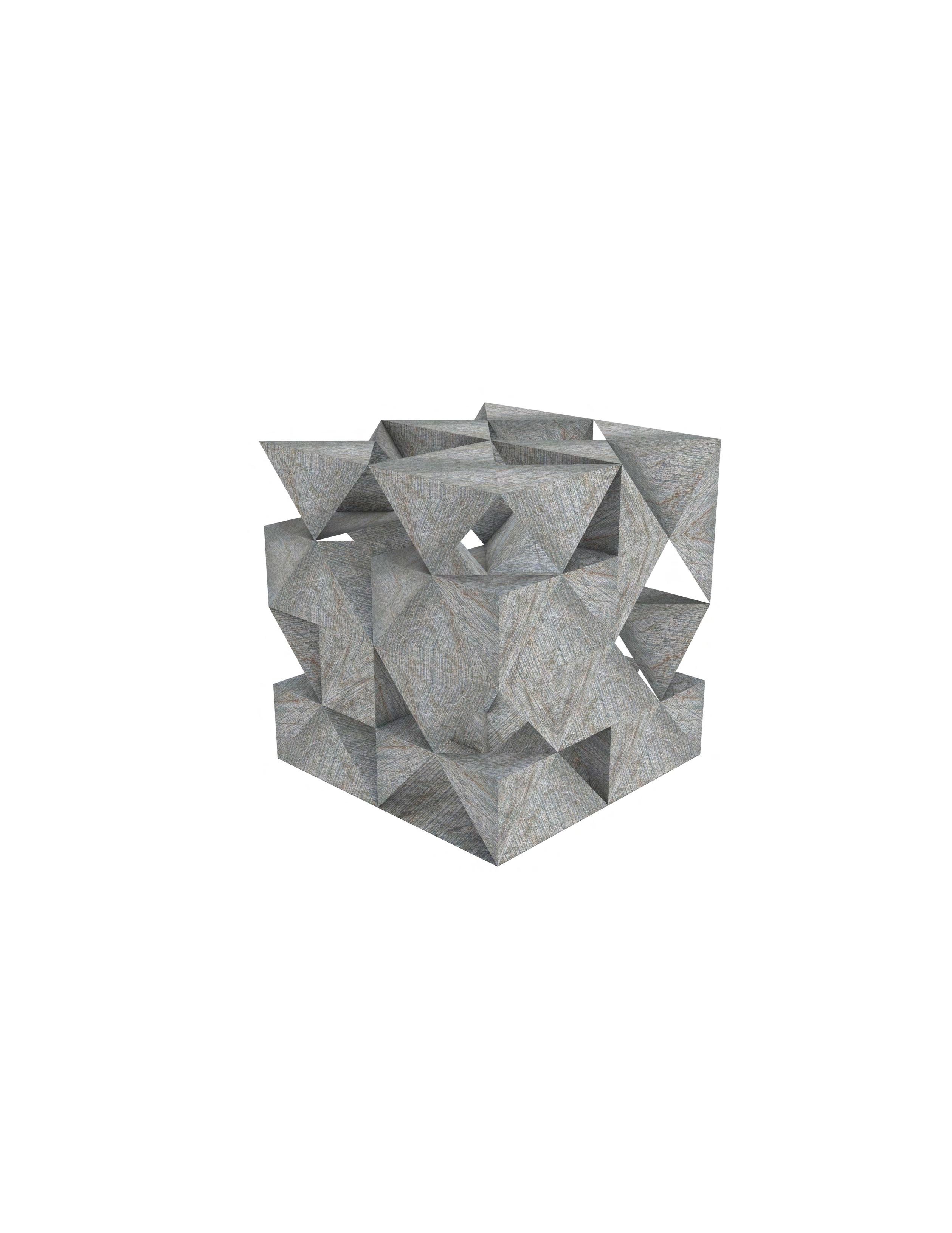
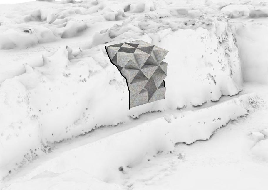
Recoder model EARTH | M.Arch. Semester 1 | Fall 2021
Cut-out in the Rock for Recorder
53
55
ARCHITECTURE FIRM

Apurva Amin Architects

LOCATION
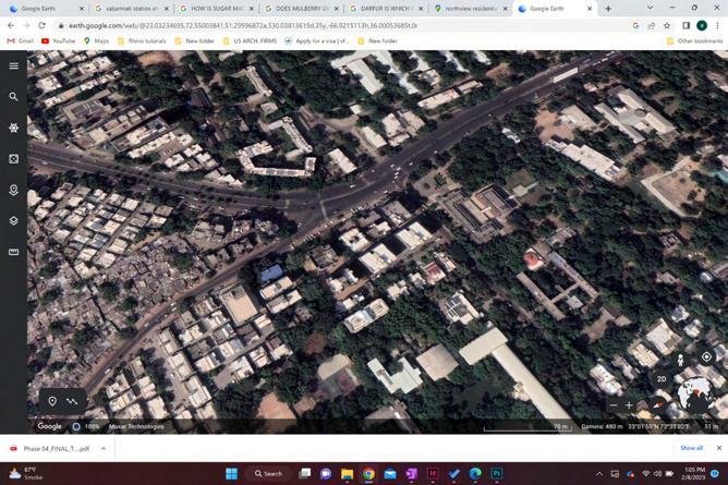
Ahmedabad , India
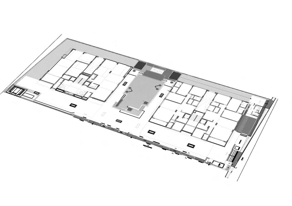
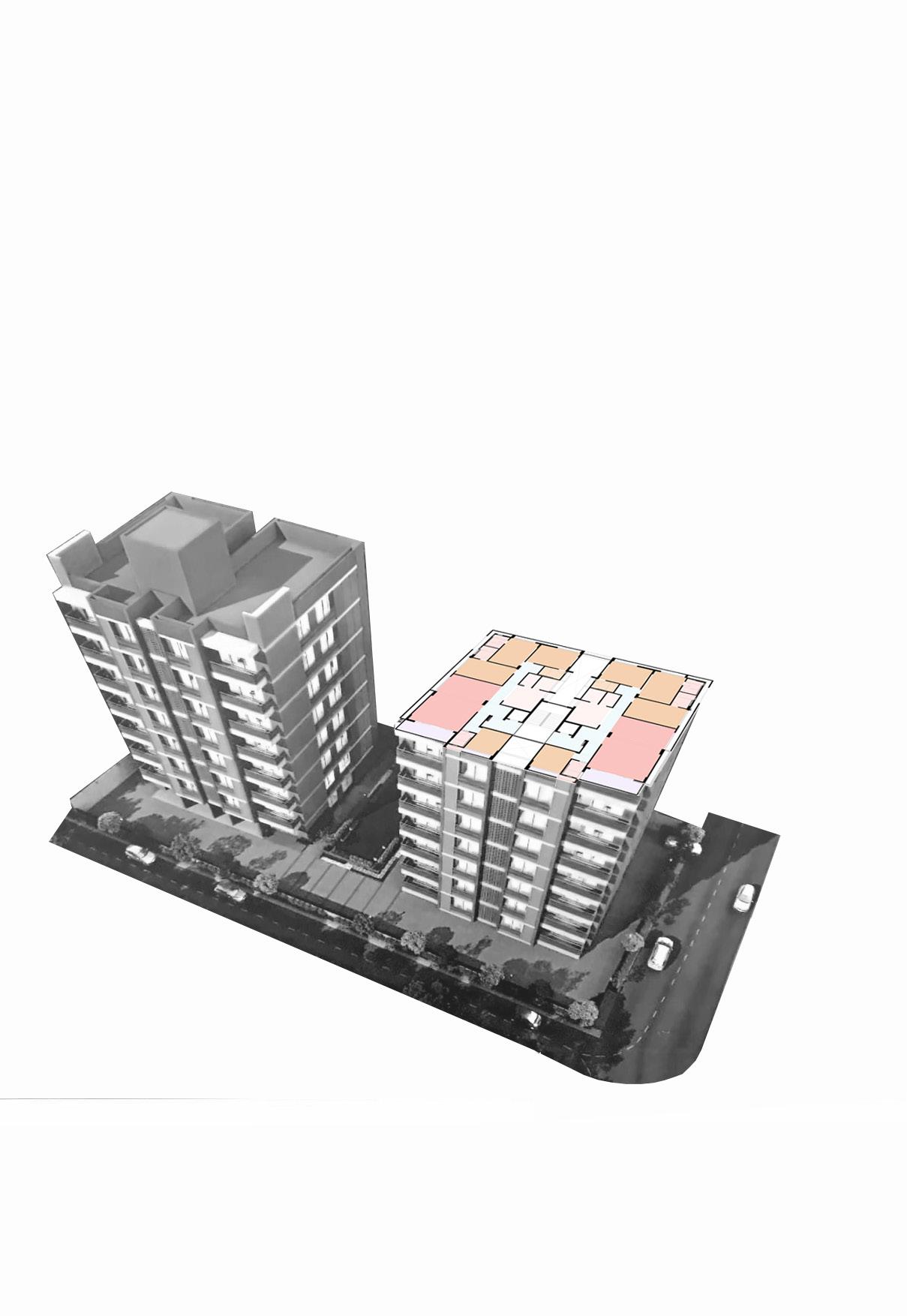
NORTHVIEW
HIGH RISE RESIDENTIAL
CLIENT S.V. Construction
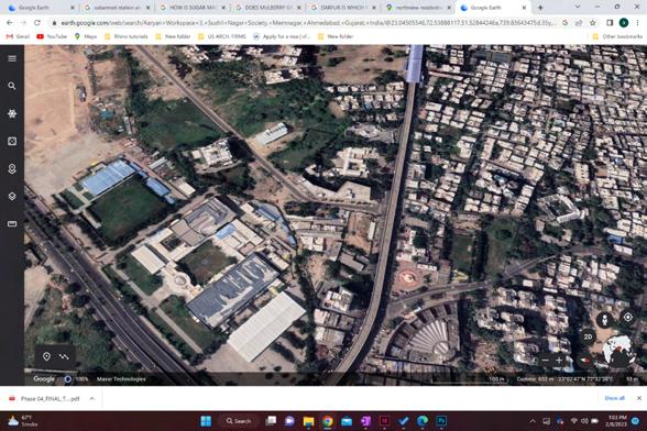
SV Northview is a multi-unit development spread over 0.60 acres and consisting of 7 floors, offering a range of 3Bedroom apartments with varying sizes. Each unit boasts a super built-up area of 1,665 square feet with a total of 28 units.The property has been meticulously planned to provide ventilated units.
Roles : SD , DD , CD , Rendering
Floor Plan Floor Plan NORTHVIEW | AAA | Spring 2020 57
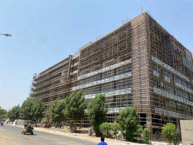
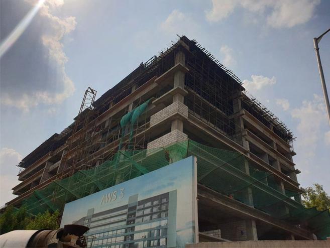
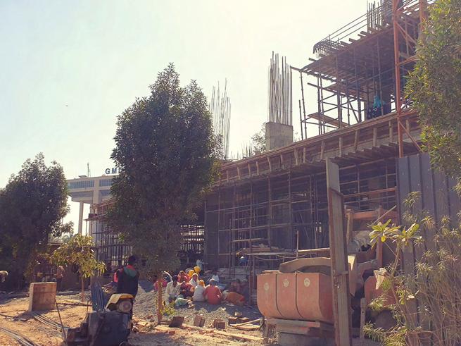
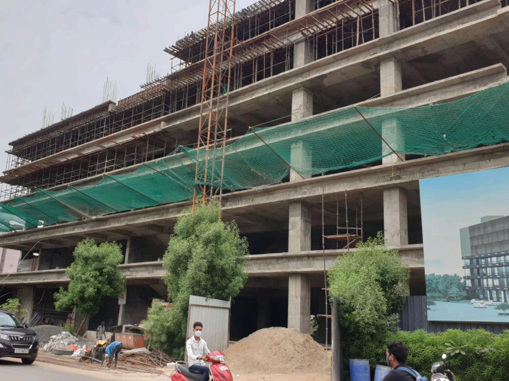
ARYAN WORKSPACE 3 COMMERCIAL
ARCHITECTURE FIRM
Apurva Amin Architects LOCATION
Ahmedabad , India
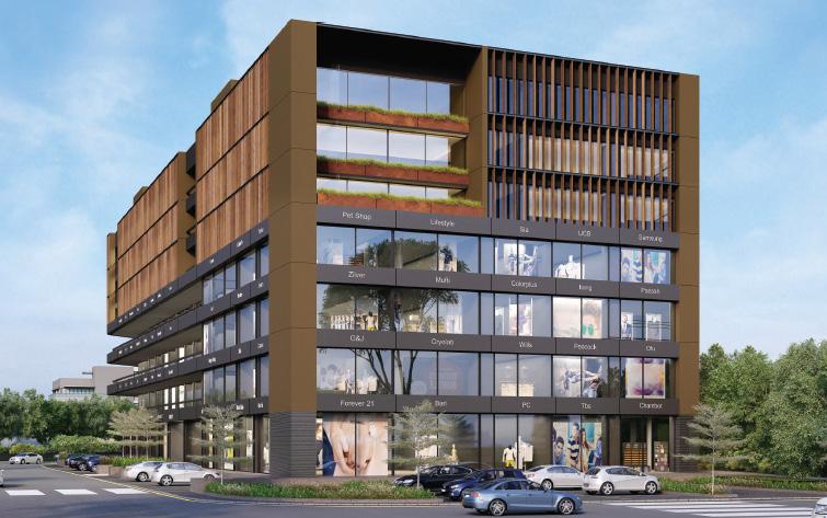
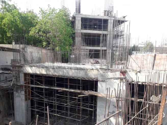
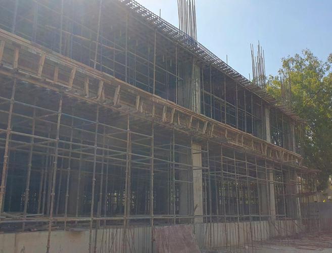
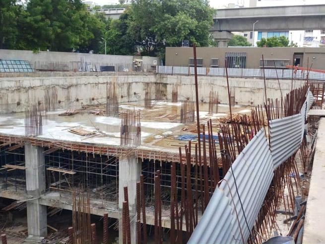
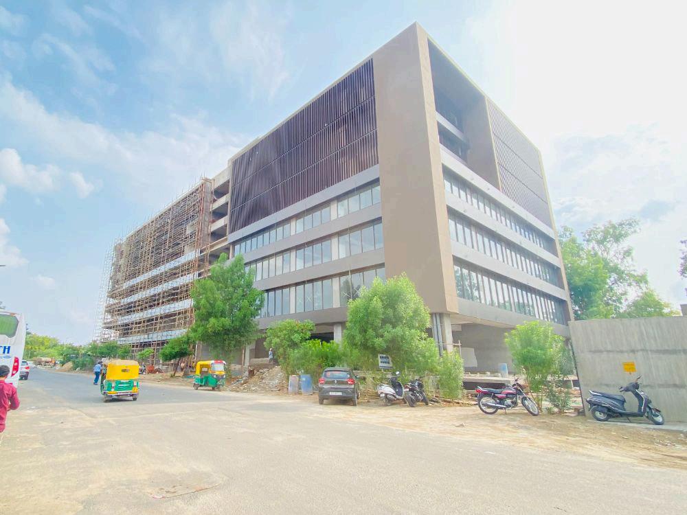
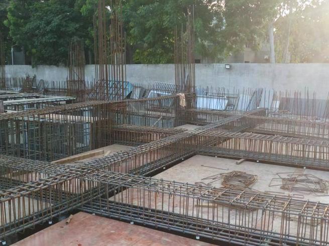
Aryan Workspace is a modern commercial building that offers a dynamic and productive office spaces. Spread over 1.02 acres, the building features 55 fully functional office spaces designed to meet the diverse needs of businesses. With its striking 6-story design, the building offers convenient parking with 4 levels Each office unit in Aryan Workspace measures 2000 square feet.
Responsibilities: DD , CD , Rendering
Professional work | Spring 202019
4,5,6 Floor Plan 1,2,3 Floor Plan Ground Floor Plan ARYAN WORKSPACE 3 | AAA | Spring 2020
ON SITE ACTUALS
BUILDING CONSTRUCTION PROCESS


61
VALENCIA LAVISH RESIDENTIAL COMMUNITY
ARCHITECTURE FIRM
Apurva Amin Architects
LOCATION
Palanpur , India
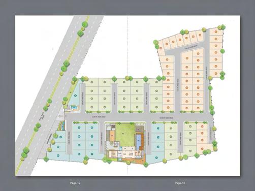
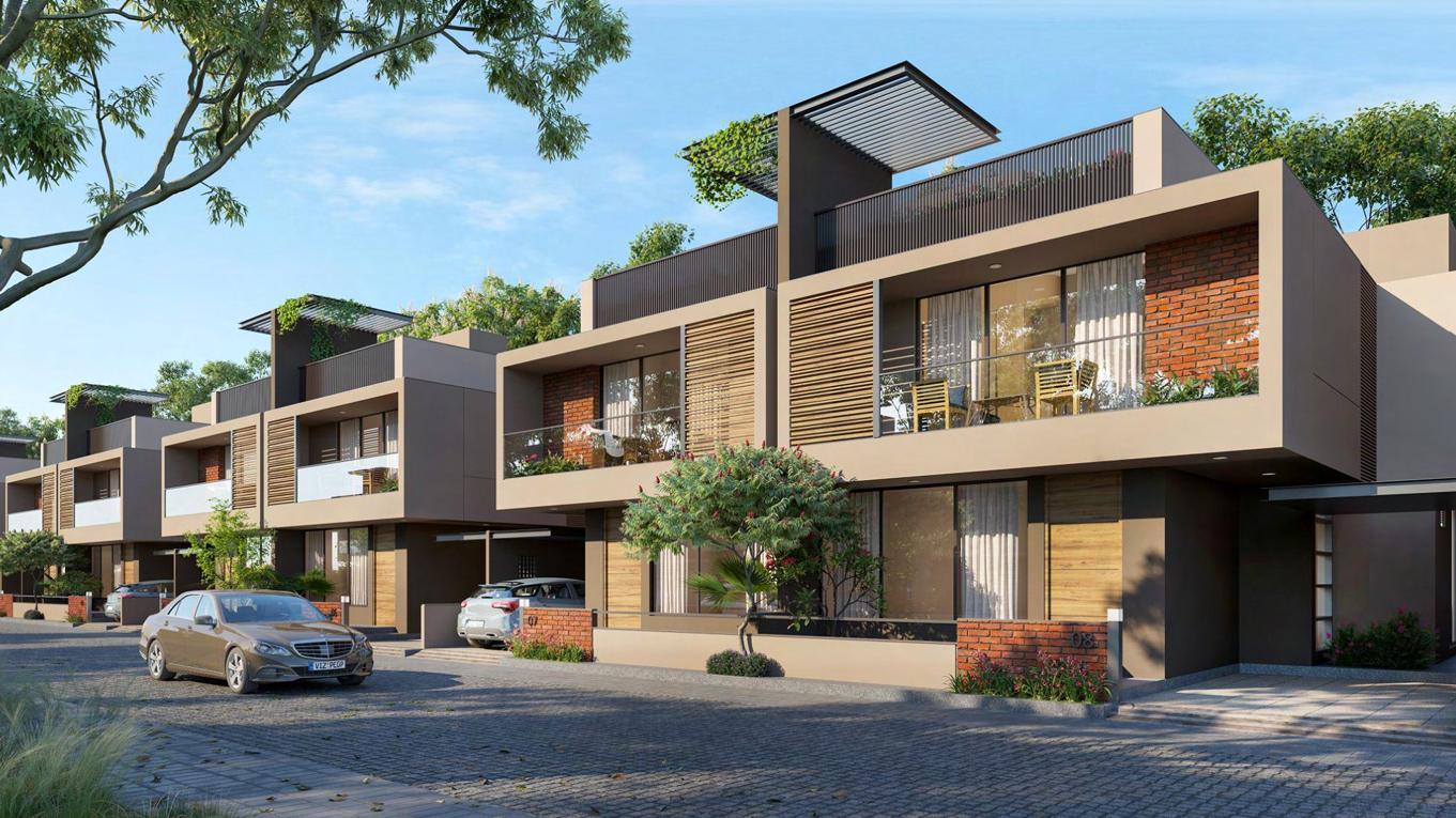
Valencia Lavish is a luxurious residential development that offers 87 spacious 3-bedroom units. Designed with comfort in mind, each unit is spread over two floors.The project is comprised of three different categories of units: executive villas, premium villas, and deluxe villas. The executive villas, of which there are 16, offer a built-up area of 53 square meters. The premium villas, with a total of 28 units, boast a generous 134 square meter built-up area .Finally, the 43 deluxe villas offer a spacious 115 square meter built-up area.
Roles : SD , DD , CD , Interior designing
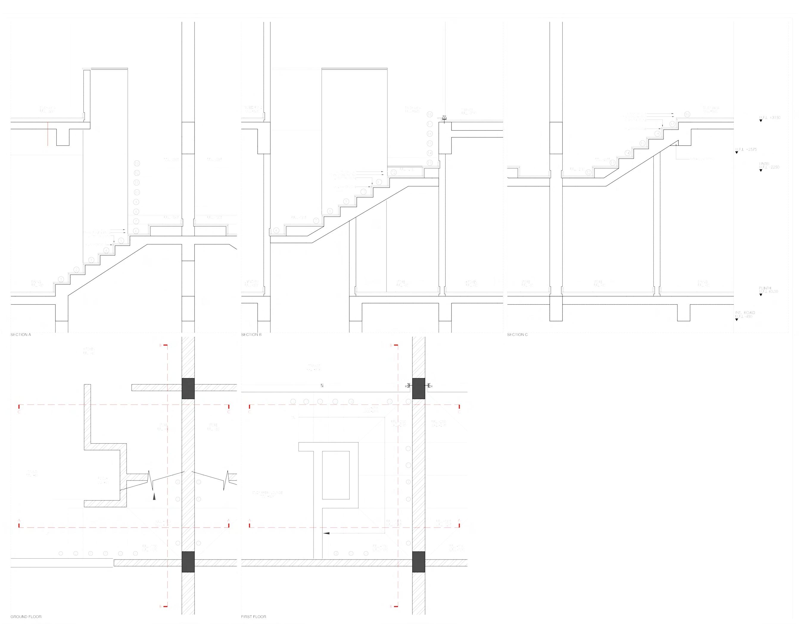
First Floor Plan Ground Floor Plan Unit section VALENCIA LAVISH | AAA | Spring 2020 63
Front Gate Plan
Front Gate Elevation
Front Gate Details
VALENCIA LAVISH | AAA | Spring 2020
Front Gate section

Railing Detail section Railing Detail plan Spring 2020 | AAA | VALENCIA LAVISH 65
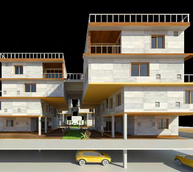
THE TERRACE HOUSE AN I NTERACTIVE RESIDENCE
COLLEGE Institute of Architecture ,Nirma University
LOCATION

Banaras, India
INSTRUCTOR
Prof. Khushnu Hoof | Deval Gandhi
MODULE
Undergraduate Housing Studio
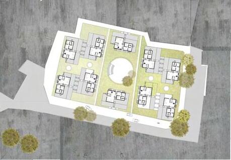
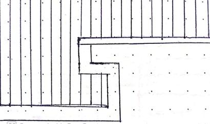
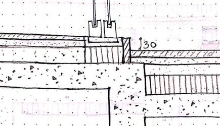
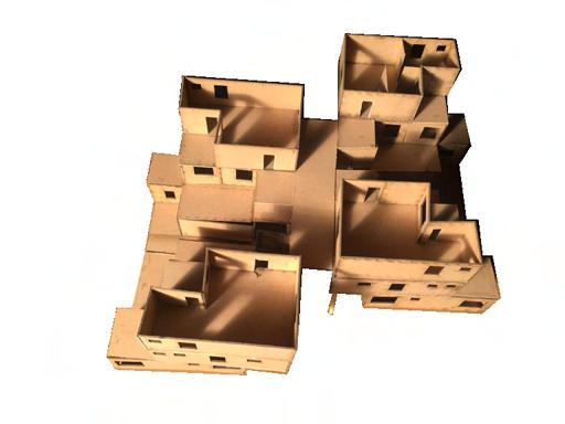
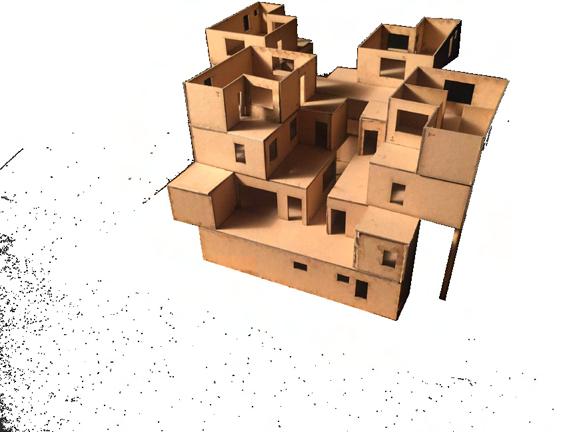
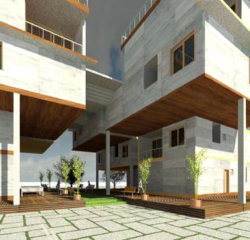
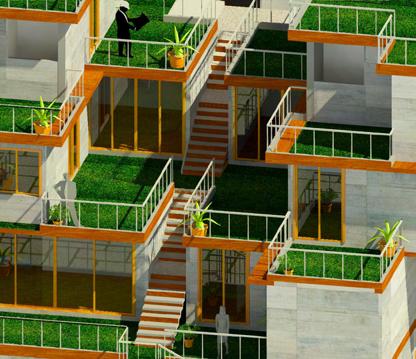
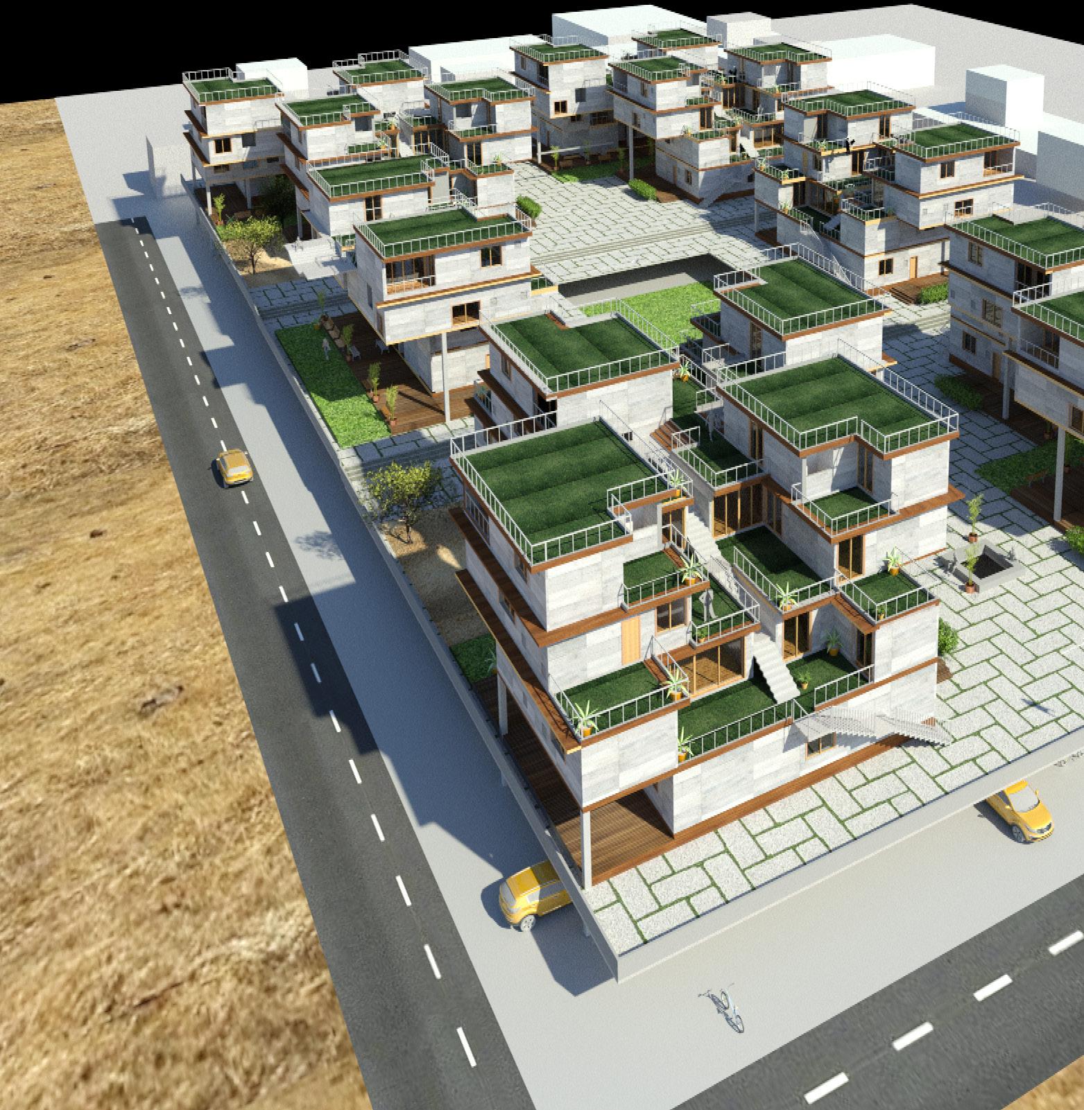
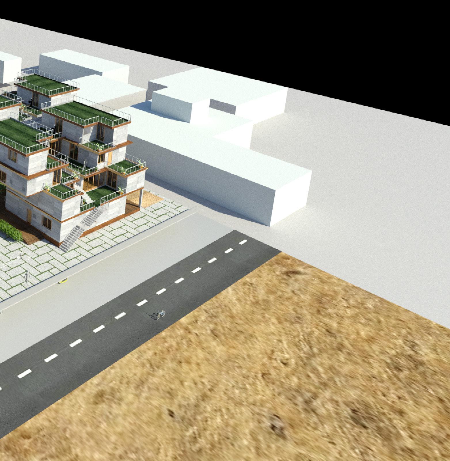
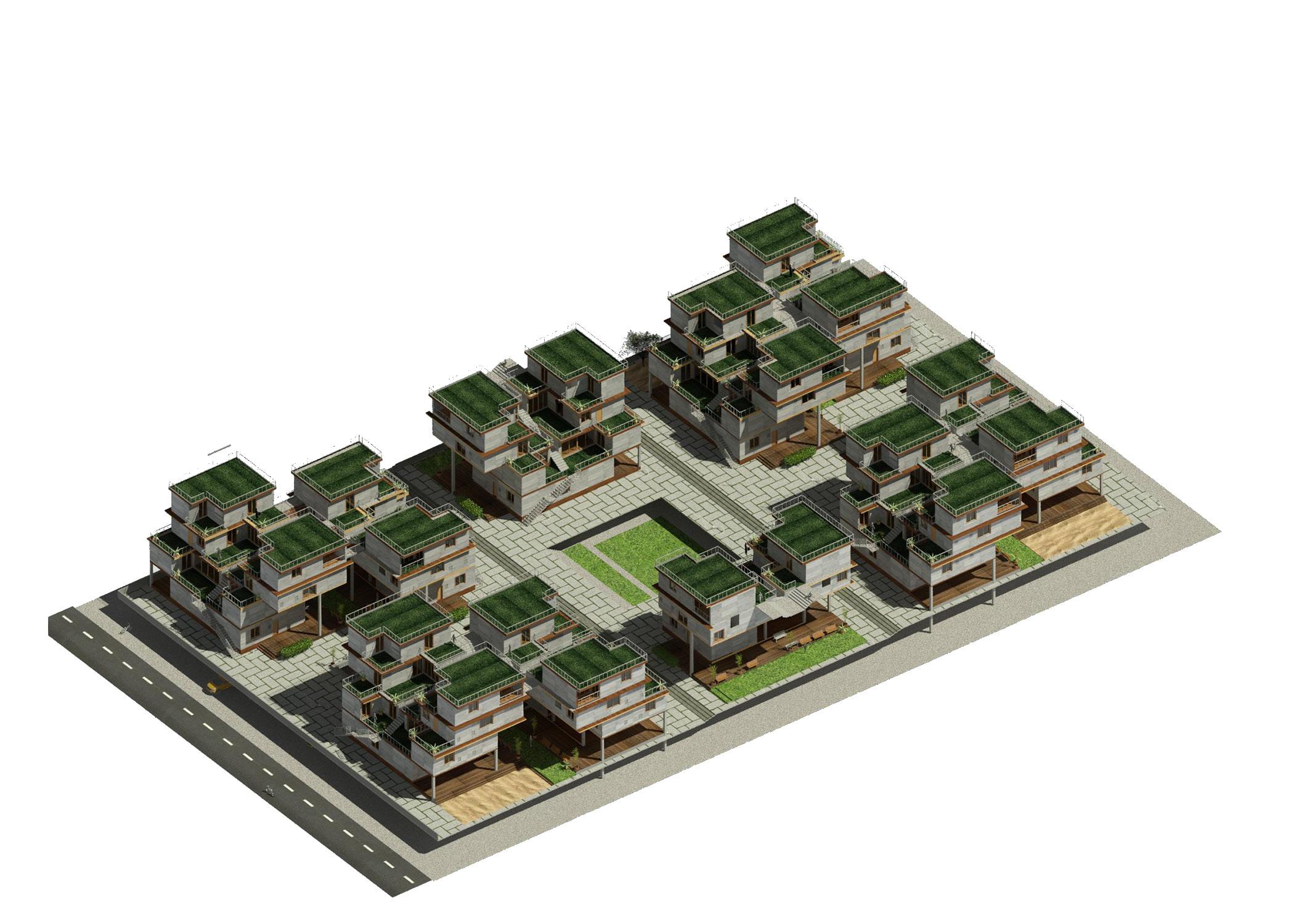
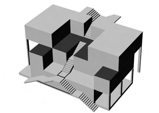
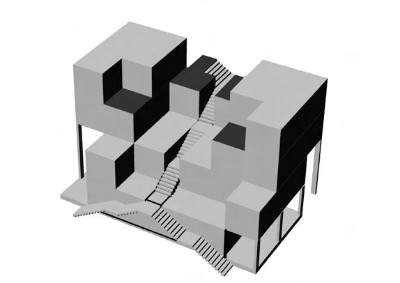
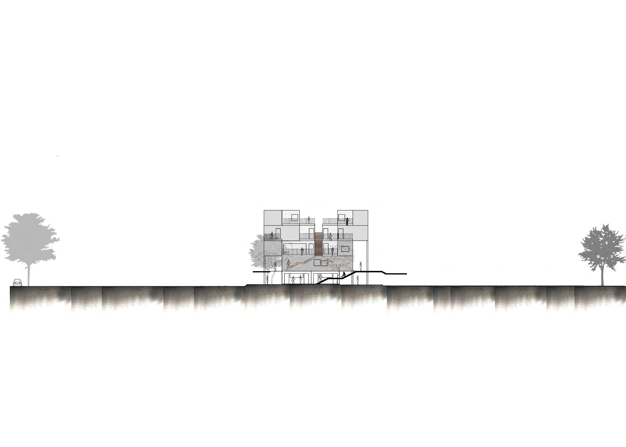
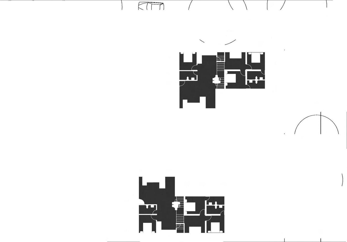
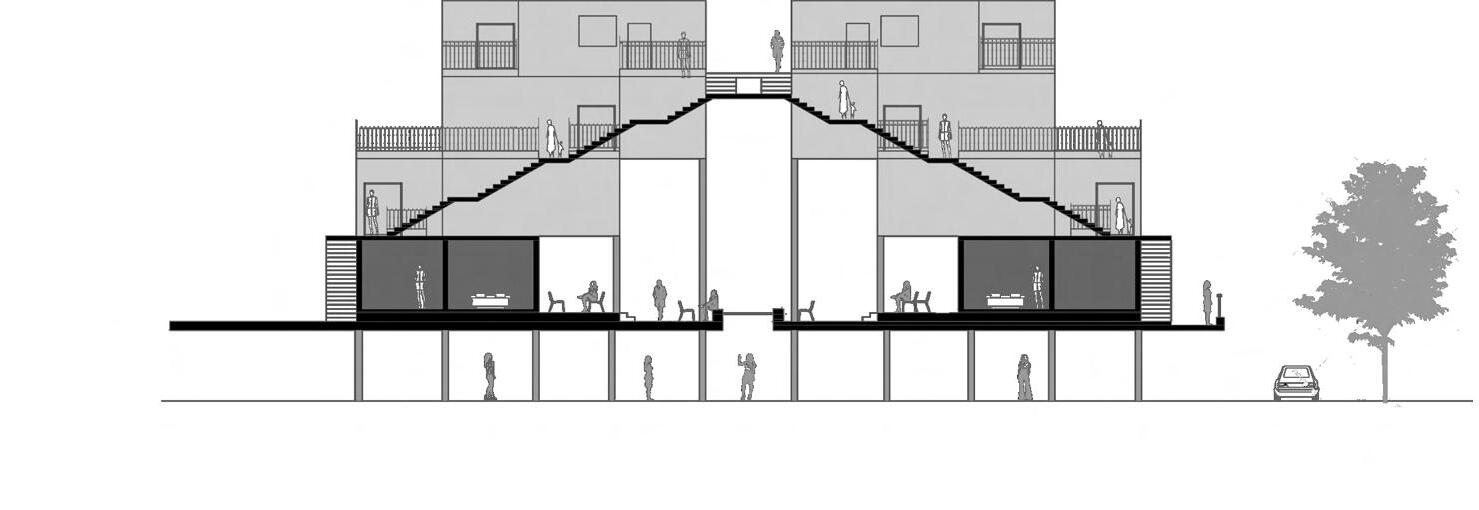
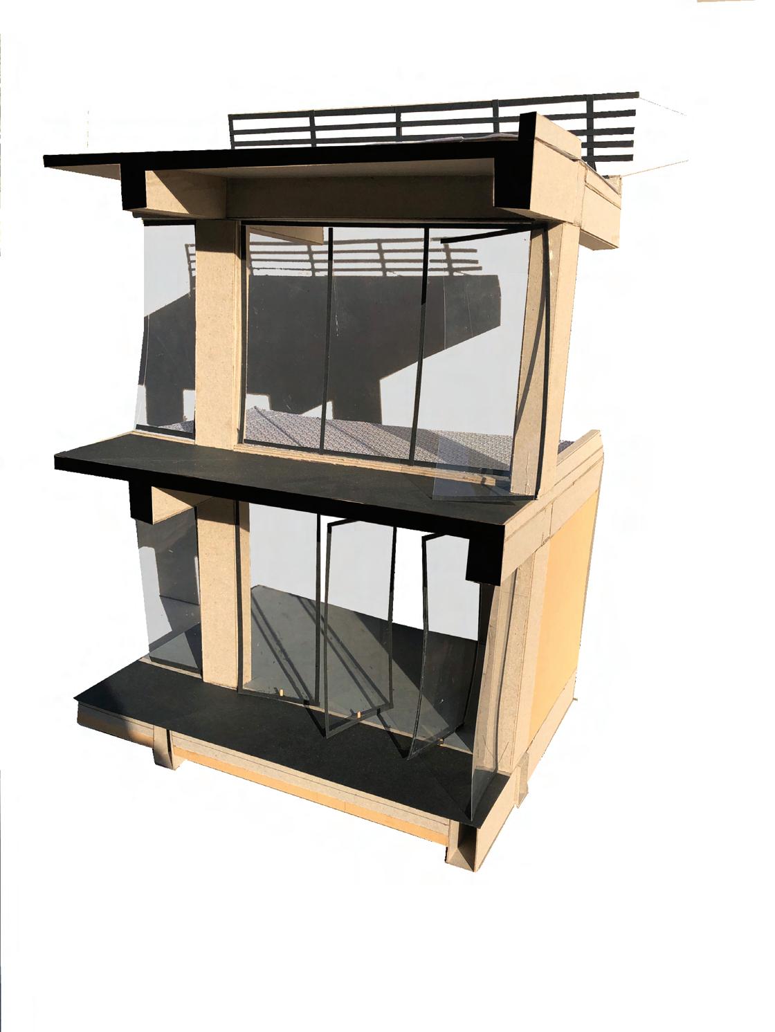
The proposed building is located in Banaras, near the banks of the river Ganges, at a distance of 700 meters. Designed as an interactive residence, it features stepped terraces that encourage social interaction among the residents. The staircase serves as the connecting element between each unit of the housing complex, and the design incorporates technology, design, and functionality to create a dynamic and interactive living environment.The cantilevered parts of the residence provide shaded outdoor public spaces between two housing clusters. To address parking and domestic animal issues in the area, the building’s foundation is elevated 3M. This unique design promises to offer a truly engaging living experience.
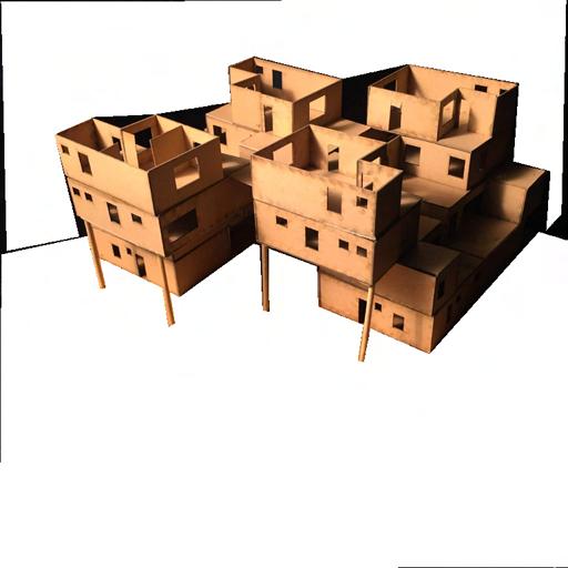
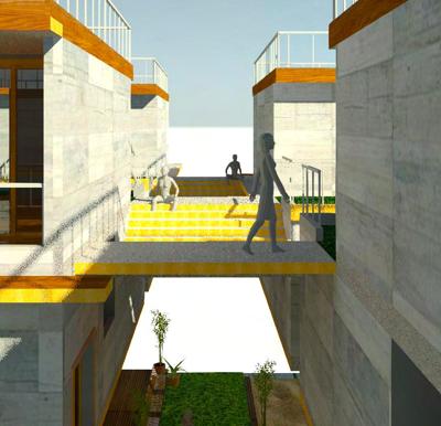
 Overhangs created by staicase
Houses connected through the landings of the staicase
A shaded public space under the units
Windows and Balconies shaded by the unit cantilevered above it.
Overhangs created by staicase
Houses connected through the landings of the staicase
A shaded public space under the units
Windows and Balconies shaded by the unit cantilevered above it.
THE TERRACE HOUSE | B.Arch. Semester 5 | Fall 2018 67
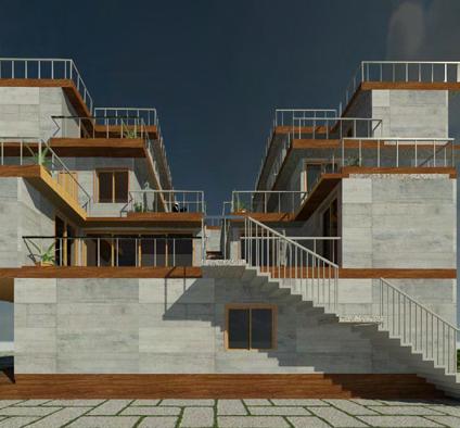
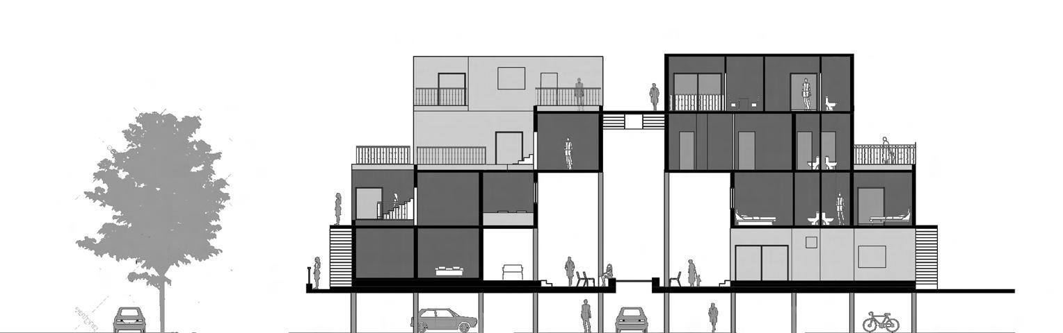
Stairs connecting the two clusters.

 Overlooking stepped terraces for each unit Balconies shaded by the cantilevered part of the above unit.
Shaded space formed between the clusters.

Staircase binds all the units together to make a single cluster
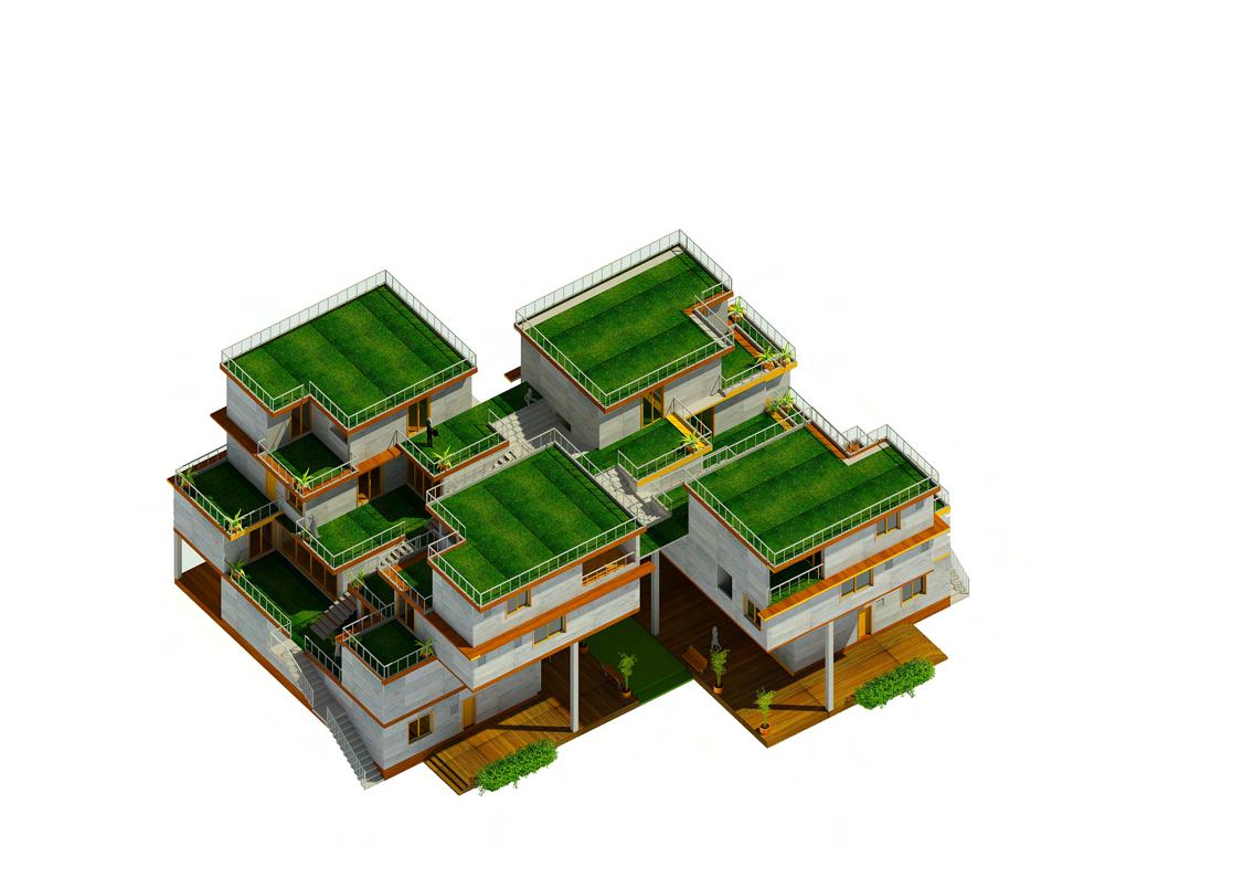
INTERACTION OF PEOPLE THROUGH TERRACES
Large unit : 110 sq.m
Medium unit : 78 sq.m
Small unit : 45 sq.m.
 Entrance to the raised plinth
Amphitheater
sand area for children
1 cluster 7 units: 1 large 3 medium 3 small
Entrance to the raised plinth
Amphitheater
sand area for children
1 cluster 7 units: 1 large 3 medium 3 small
THE TERRACE HOUSE | B.Arch. Semester 5 | Fall 2018
Shaded area cluster for
2 clusters arranged 14 units


Fourth floor - 2 small units
Raised plinth car parking on ground level area of for sitting


Third floor - 2 medium units
Overlooking terraces
Second floor - 1 medium, 1 small unit
Ground floor - 1 large unit
71
Second Floor plan
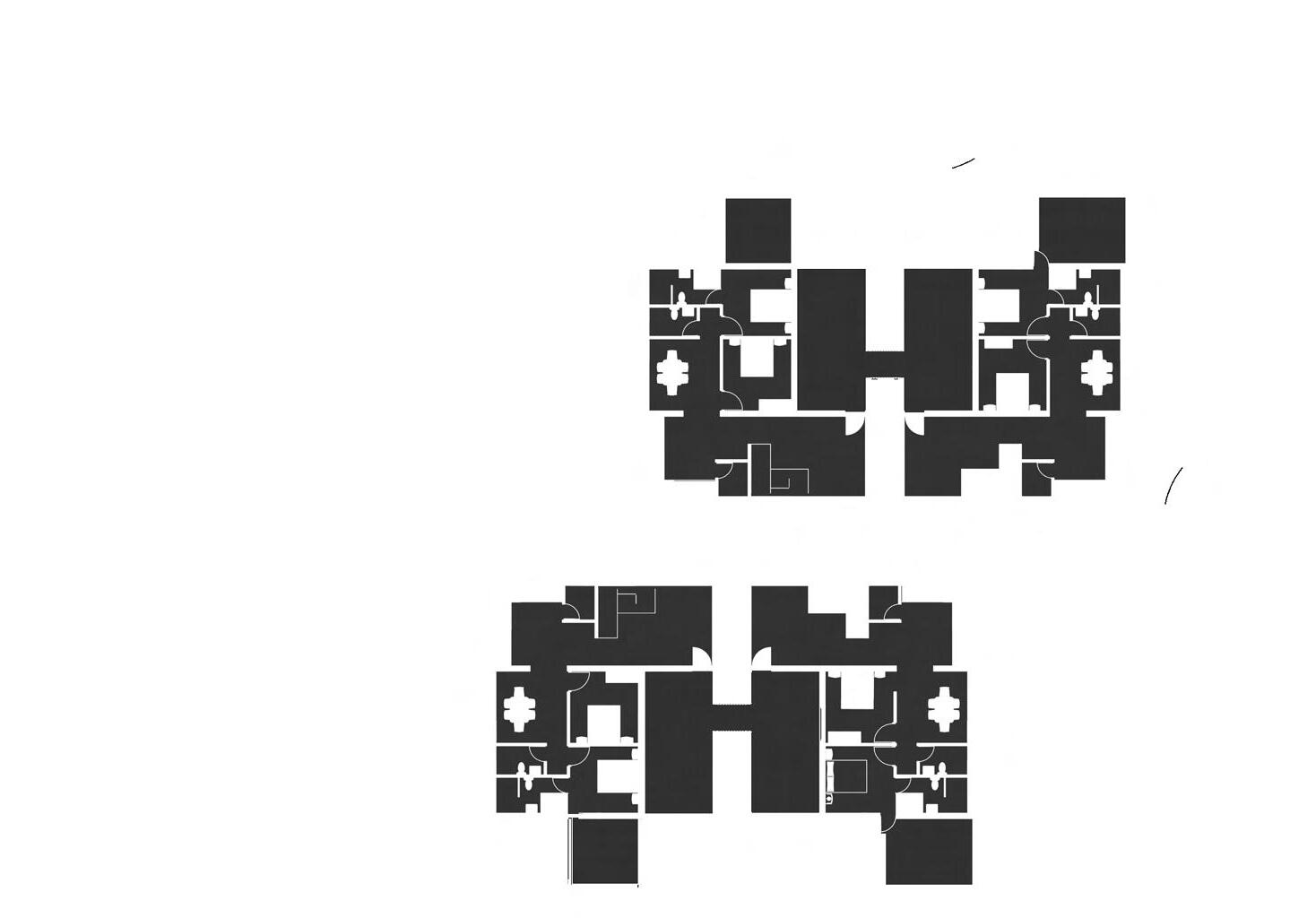

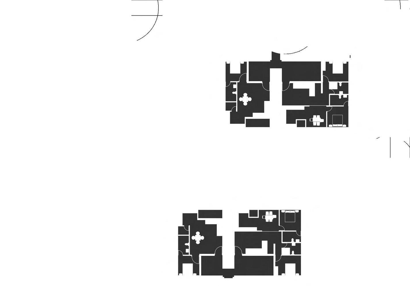

First Floor plan
THE TERRACE HOUSE | B.Arch. Semester 5 | Fall 2018


Third Floor plan
73
Fourth Floor plan
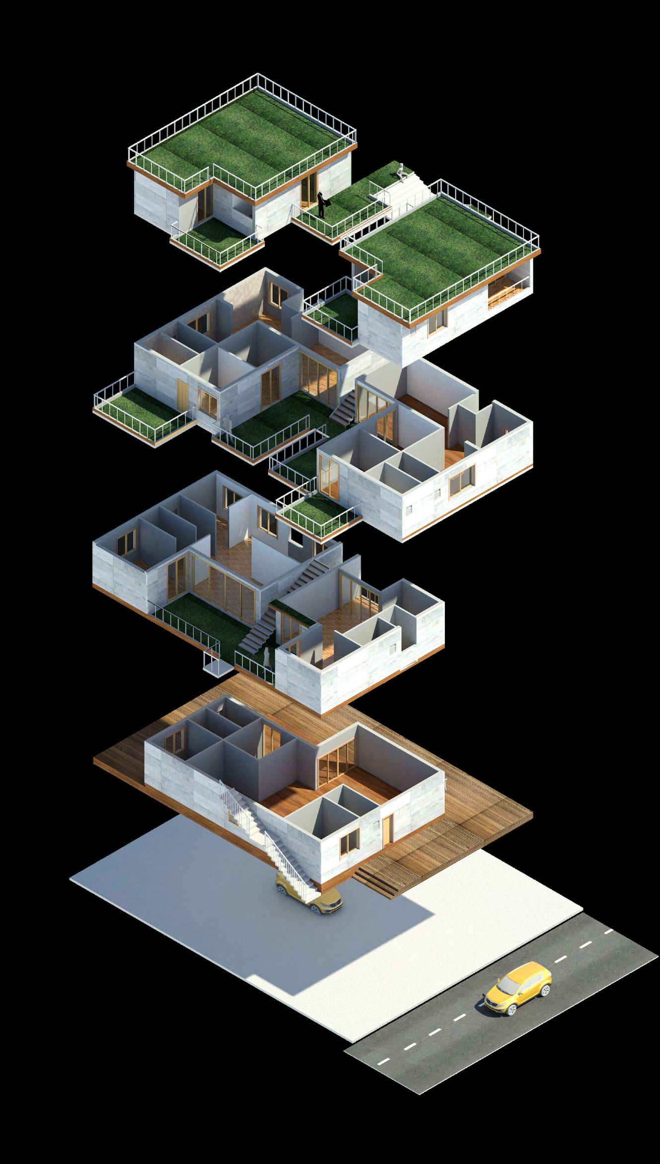
Fourth Floor Exploded view Third Floor
Floor First Floor Ground Floor THE TERRACE HOUSE | B.Arch. Semester 5 | Fall 2018
Second
First floor services plan
Second floor services plan
Third floor services plan duct
Fourth floor services plan
Overlapping of the service areas vertically for the ease of servicing in this cantilevered structure
services
B.Arch. Semester 5 | Fall 2018 | THE TERRACE HOUSE 75
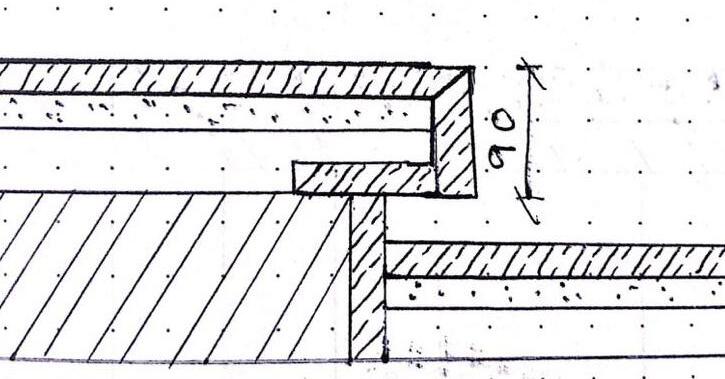
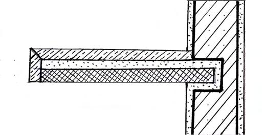
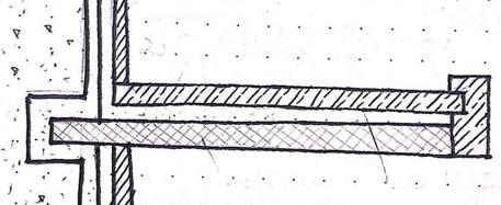
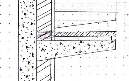
CONCRETE SLAB 100 MM BBCC LAYER 150 MM COMPACTED EARTH 9MM RUBBER FLOORING 20MM KOTA SONE 40MM BED MORTAR MOSAIC MORTAR BBCC LAYER CONCRETE SLAB PLASTER FLOORING SONE MORTAR MM MM EARTH ELEVATION FLOORING SONE MORTAR +8440 FINISHED TERRACE FINISH THE TERRACE HOUSE | B.Arch. Semester 5 | Fall 2018

Railing Detail
section detail B.Arch. Semester 5 | Fall 2018 | THE TERRACE HOUSE 77
Wall
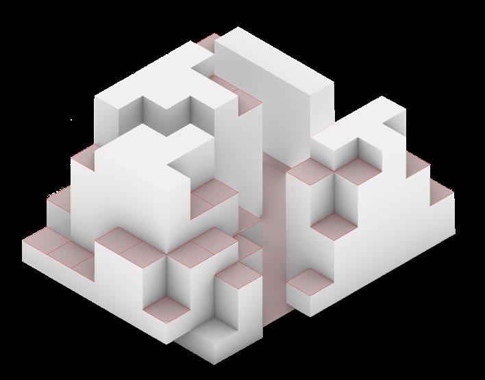
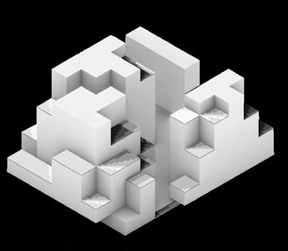
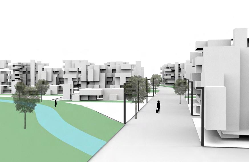
WALKABLE NEIGHBOURHOOD PARAMETRIC URBAN
COLLEGE
Institute of Architecture, Nirma University

LOCATION
Ashram road, Ahmedabad , India
INSTRUCTOR
Prof.
 Arpi Maheshwari | Radhika Amin |

Dhaval Chauhan
MODULE

Undergraduate Housing Studio
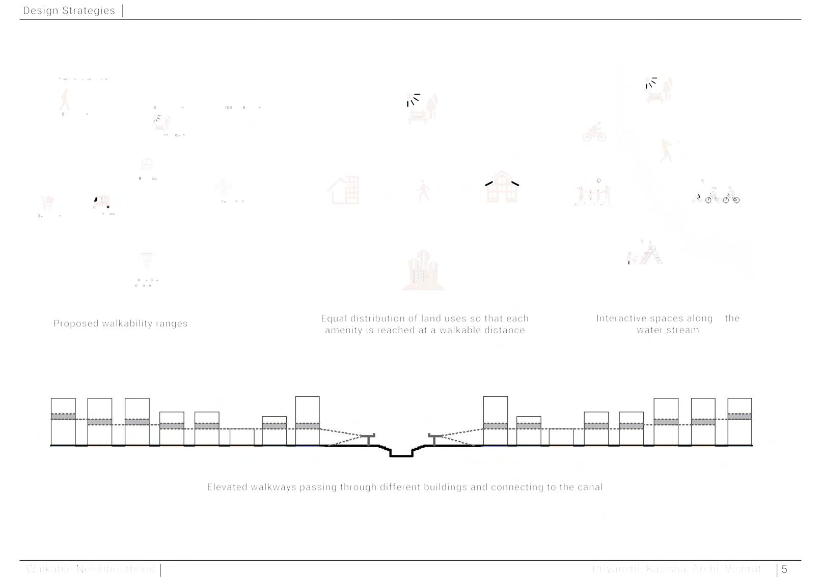
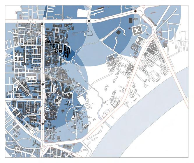
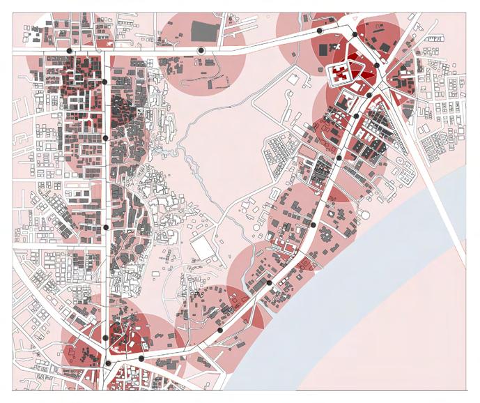
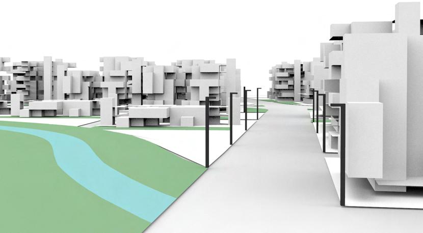
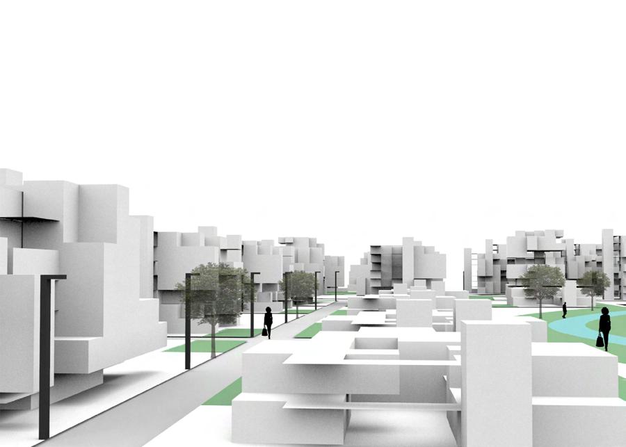
The proposed project explores walkability as a substitute fortraditional urban mobility. It employs a parametric approach to urban design, which means that the roads and buildings are designed to make the neighborhood accessible by foot. The parametric design process generates multiple options for road layouts and selects the one that provides the shortest route from one point to another. For the buildings, the design links them through elevated walkways, ensuring the shortest and most visually appealing route between two points.
Road Network Psuedocodes
bus stops catering houses on the primary road (walkable radius of 250 m)
AMTS bus stops catering houses on the primary road (walkable radius of 250 m)
Psuedocodes
Road Network
32 feet ring road Gandhi Ashram R.T.O 32 feet ring road Ashram Circle 32 feet ring road Ashram R.T.O Circle 32 feet ring road Gandhi Ashram R.T.O Circle
BRTS bus stops catering houses on the primary road (walkable radius of 250 m)
BRTS bus stops catering houses (walkable radius of 250 m)
Psuedocodes 32 feet
water stream and bus stops are retained.
Circles of 250 m radius are made from the existing bus stops.
catering houses only on the primary road (walkable radius of 250 m)
Neighbourhood
Psuedocodes Priyanshi, Kavisha, Archi, Vishrut Walkable Neighbourhood 7
The existing water stream and bus stops are retained. Circles
stream and bus stops are retained. Circles of 250 m radius are made from the existing bus stops. Shuttle stops are marked at the intersection points which are more than 200m apart shuttle stops to form secondary roads. Shuttle stops are added where the distance between two stops is more than 250m R.T.O Circle
Shuttle stops are marked at the intersection points which are more than 200m apart shuttle stops to form secondary roads.
Connect all the shuttle stops to form the secondary roads.
Shops catering houses only on the primary road (walkable radius of 250 m)
Connect all the shuttle stops to form the secondary roads.
Community spaces concentrated site. (walkable radius of 250
Priyanshi, Kavisha, Archi, Vishrut
Priyanshi, Walkable Neighbourhood
Shuttle stops are added where the distance between two stops is more than 250m
Neighbourhood 7
Priyanshi, Kavisha, Archi, Vishrut Walkable Neighbourhood 13 Residential Buildings Commercial and Institutional Buildings 50% Of the total site area i.e. 725,000 sq. m. 20% Of the total site area i.e. 290,000 sq. m. High Density : 120 people Medium Density : 80 people Low Density : 40 people High Density : 190 people Medium Density : 140 people Low Density : 90 people Density Distribution Priyanshi, Kavisha, Archi, Vishrut Walkable Neighbourhood 13 Residential Buildings Commercial and Institutional Buildings 50% Of the total site area i.e. 725,000 sq. m. 20% Of the total site area i.e. 290,000 sq. m. High Density : 120 people Medium Density : 80 people Low Density : 40 people High Density : 190 people Medium Density : 140 people Low Density : 90 people Density Distribution WALKABLE NEIGHBOURHOOD| B.Arch Semester 7| Fall 2019 79
Priyanshi, Kavisha, Archi, Vishrut Neighbourhood 7 32 feet 32 feet ring road Ashram
Density distribution
for road network Site analysis
Pseudo codes
Inferences
Open Spaces + Residences + Commercial buildings + Trees + Street Network Priyanshi, Kavisha, Archi, Vishrut Walkable Neighbourhood 13 Residential Buildings Commercial and Institutional Buildings 50% Of the total site area i.e. 725,000 sq. m. 20% Of the total site area i.e. 290,000 sq. m. High Density : 120 people Medium Density : 80 people Low Density : 40 people High Density : 190 people Medium Density : 140 people Low Density : 90 people Density Distribution Priyanshi, Kavisha, Archi, Vishrut Walkable Neighbourhood 13 Residential Buildings Commercial and Institutional Buildings 50% Of the total site area i.e. 725,000 sq. m. 20% Of the total site area i.e. 290,000 sq. m. High Density : 120 people Medium Density : 80 people Low Density : 40 people High Density : 190 people Medium Density : 140 people Low Density : 90 people Density Distribution Priyanshi, Kavisha, Archi, Vishrut
32 feet ring road Ashram R.T.O Circle Ashram Circle
16BAR004, 16BAR005, 16BAR013, SINGLE LAYER ONE POLYGON TWO POLYGONS THREE POLYGONS OPEN SPACE Data Analysis • The importance es is not realized ed number of provide sufficient BUILDINGS 9 residences • 40 residences 25-30 residences • 1 commercial 4 commercial • 4 commercial Open Spaces + Residences + Commercial buildings + Trees + Street Network
32 feet ring road Ashram R.T.O Circle Ashram Circle
Community spaces concentrated only on a part of the site. (walkable radius of 250 m) Walkable Neighbourhood
The existing water stream and bus stops are retained. Circles of 250 m radius are made from the existing bus stops. Shuttle stops are marked at the intersection points which are more than 200m apart
Shuttle stops are added where the distance between two stops is more than 250m
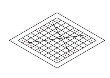
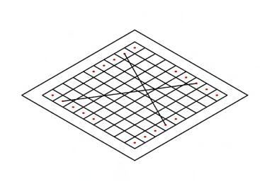
1. Make a plot of size 42 m x 42 m.
7. A pathway is created between the 2 points.8. The cells which are not used as pathway are used as built form.
7. A pathway is created between the 2 points.8. The cells which are not used as pathway are used as built form.
2. Leave a boundary of 4 m on all sides.3. Insert a grid of 4 m x 4 m in the remaining plot.
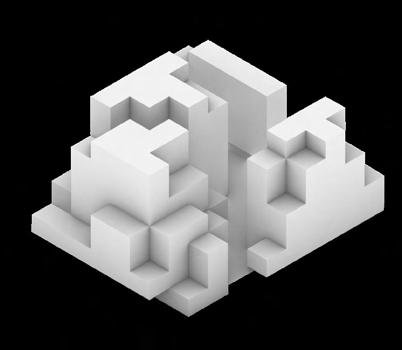
9. The built form is extruded 3 m to create space.
4. Select 5 cells near the boundary of the plot which will be the access points.
9. The built form is extruded 3 m to create space.

7. A pathway is created between the 2 points.8. The cells which are not used as pathway are used as built form.
9. The
4. Select 5 cells near the boundary of the plot which will be the access points.
5. Join any 2 points to create a path.
6. Create shortest walk between the 2 selected points.
the 2 points.
the 2 points.8. The cells which are not used as pathway are used as built form.
COMMERCIAL BUILDING PSEUDO CODES GENERATIONS
8. The cells which are not used as pathway are used as built form.
10. Move the walkway 1.5 m in Z direction so that mezzanines are created to increase interactivity.
11. Move the floor plate in Z- direction.
12. Select one cell from the plane.
11. Move the floor plate in Z- direction.
12. Select
13.
10. Move the walkway 1.5 m in Z direction so that mezzanines are created to increase interactivity.
Morphology Commercial - Generation 1
9. The built form is extruded 3 m to create space. direction to increase


Priyanshi, Kavisha, Archi, Vishrut Walkable Neighbourhood 24
11. Move the floor plate in Z- direction. 12. Select one cell from the plane.
11. Move the floor plate in Z- direction. 12. Select one cell from the plane.
9. The built form is extruded 3 m to create space. direction increase
Priyanshi, Kavisha, Archi, Vishrut 25
Priyanshi, Kavisha, Archi, Vishrut 25
VIEWS
10. Move the walkway 1.5 m in Z direction so that mezzanines are created to increase interactivity.
11. Move the floor plate in Z- direction.
12. Select one cell from the plane.
selected
Priyanshi, Walkable Neighbourhood
Priyanshi, Kavisha, Archi, Vishrut
Walkable Neighbourhood
0 0.2 0.4 0.6 0.8 1 1 2 3 4 5 G1 01 0 0.2 0.4 0.6 0.8 1 1 2 3 4 5 G1 02 0 0.2 0.4 0.6 0.8 1 1 2 4 5 G1 03 0 0.2 0.4 0.6 0.8 1 1 2 5 G1 04 0 0.2 0.4 0.6 0.8 1 1 5 G1 05 G1 08 G1.01 G1.02 G1.03 G1.04 G1.05
Psuedocode Commercial
built
Psuedocode Commercial Priyanshi, Kavisha, Archi, Vishrut Walkable Neighbourhood
25
Psuedocode Commercial Priyanshi, Kavisha, Archi, Vishrut Walkable Neighbourhood 25
Psuedocode Commercial
Walkable Neighbourhood 1. Make a plot of size 42 m x 42 m. 2. Leave
Walkable Neighbourhood
5. Join
70
Commercial WALKABLE NEIGHBOURHOOD| B.Arch Semester 7| Fall 2019
% are
on all sides.3. Insert a grid of 4 m x 4 m in the remaining plot.
Walkway inside the complex Interactive spaces at different levels
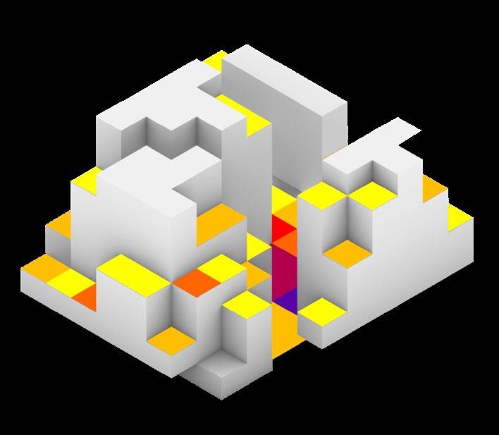
Fitness Criteria
FITNESS CRITERIA
Psuedocode Commercial
Join any 2 points to create a path.
Psuedocode
Walkway inside the complex Interactive spaces at different levels Stairways going on
6. Create shortest walk between the 2 selected points.
Kavisha, Archi, Vishrut 24
Walkway inside the complex Interactive spaces at different levels
- 90 % of the grid cells on the plane selected along with their closest points.

complex different levels
14. Extrude the selected cells.
Fitness Criteria
7. A pathway is created between the 2 points. 8. The cells which are not used as pathway are used as built form.
Fitness Criteria
Maximizing area of open spaces
The height between blocks always the walkways building
9. The built form is extruded 3 m space.

Maximizing
Walkable Neighbourhood
The height difference between the building blocks always keeps the walkways of the building shaded.
Stairways going on both above and below the floor walkway
10. Move the walkway 1.5 m in Z direction so that mezzanines are created to increase interactivity.
15. Repeat the same process for multiple floors till there are 5 cells left.
Walkable Neighbourhood
Maximizing area of open spaces
Walkable Neighbourhood
11. Move the floor plate in Z- direction.
12. Select one cell from the plane.
Maximizing Sun Exposure Maximizing
Priyanshi, Kavisha, Archi, Vishrut
Stairways going on both above and below the floor from the
The height difference between the building blocks always keeps the walkways of the building shaded.
Maximizing Sun Exposure Maximizing Shadow Maximizing
Maximizing area of open spaces
The height difference between the building blocks always keeps the walkways of the


Walkable Neighbourhood
Priyanshi, Kavisha, Archi, Vishrut
Neighbourhood 26
open spaces
Maximizing Sunlight Hours Maximizing
27 2
Priyanshi, Kavisha, Walkable
Morphology Strategies Commercial Fitness Criteria Maximizing
of
Neighbourhood
area
Priyanshi, Kavisha, Archi, Vishrut 23
Sun ExposureMaximizing ShadowMaximizing Sunlight Hours Maximizing Volume Priyanshi, Kavisha, Archi, Vishrut Walkable Neighbourhood Morphology Commercial - Generation 1 0 0.2 0.4 0.6 0.8 1 1 2 3 4 5 G1 01 0 0.2 0.4 0.6 0.8 1 1 2 3 4 5 G1 02 0 0.2 0.4 0.6 0.8 1 1 2 3 4 5 G1 03 0 0.2 0.4 0.6 0.8 1 1 2 3 4 5 G1 04 0 0.2 0.4 0.6 0.8 1 1 3 4 5 G1 05 0 0.2 0.4 0.6 0.8 1 1 2 3 4 5 G1 06 0 0.2 0.4 0.6 0.8 1 1 2 3 4 5 G1 07 0 0.2 0.4 0.6 0.8 1 1 2 3 4 5 G1 08 0 0.2 0.4 0.6 0.8 1 1 2 3 4 5 G1 09 0 0.2 0.4 0.6 0.8 1 1 3 4 5 G1 10 G1.01 G1.02 G1.03 G1.04 G1.05 G1.06 G1.07 G1.08 G1.09 G1.10
Leave a boundary of 4 m
Priyanshi,
81
PASSIVE INFILL BUIDLING
COLLEGE
Georgia Institute of Technology
LOCATION
Bsoston , MA
INSTRUCTOR
Prof. Russel Gentry | Michael Gamble
| Todd Mowinski | Howard Wertheimer
MODULE
Integrated Building Design
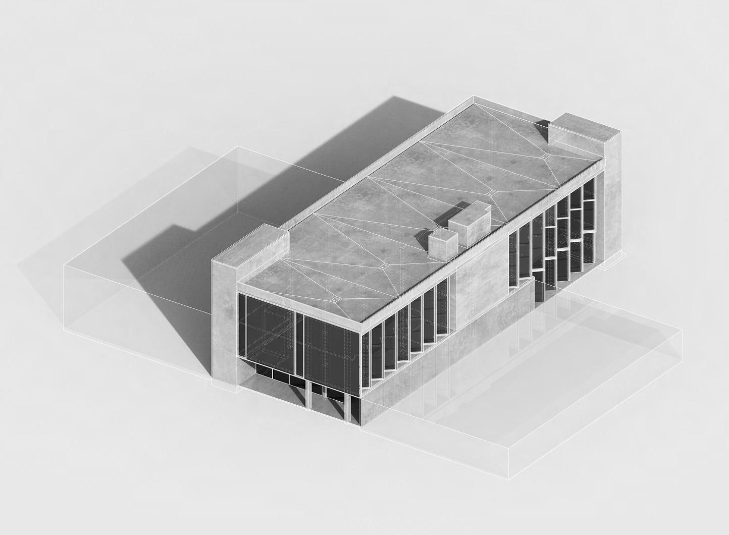
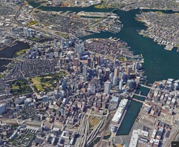
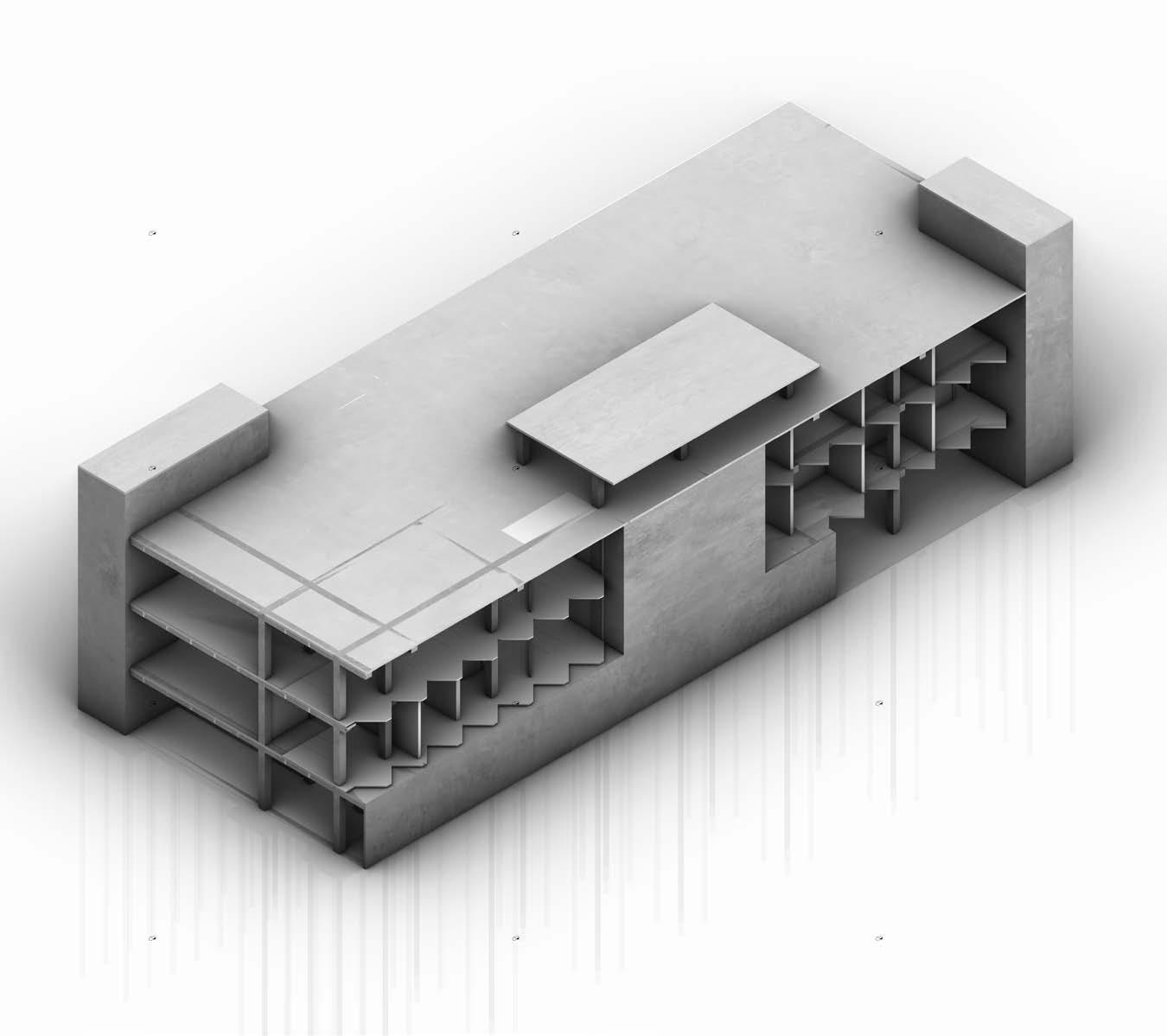
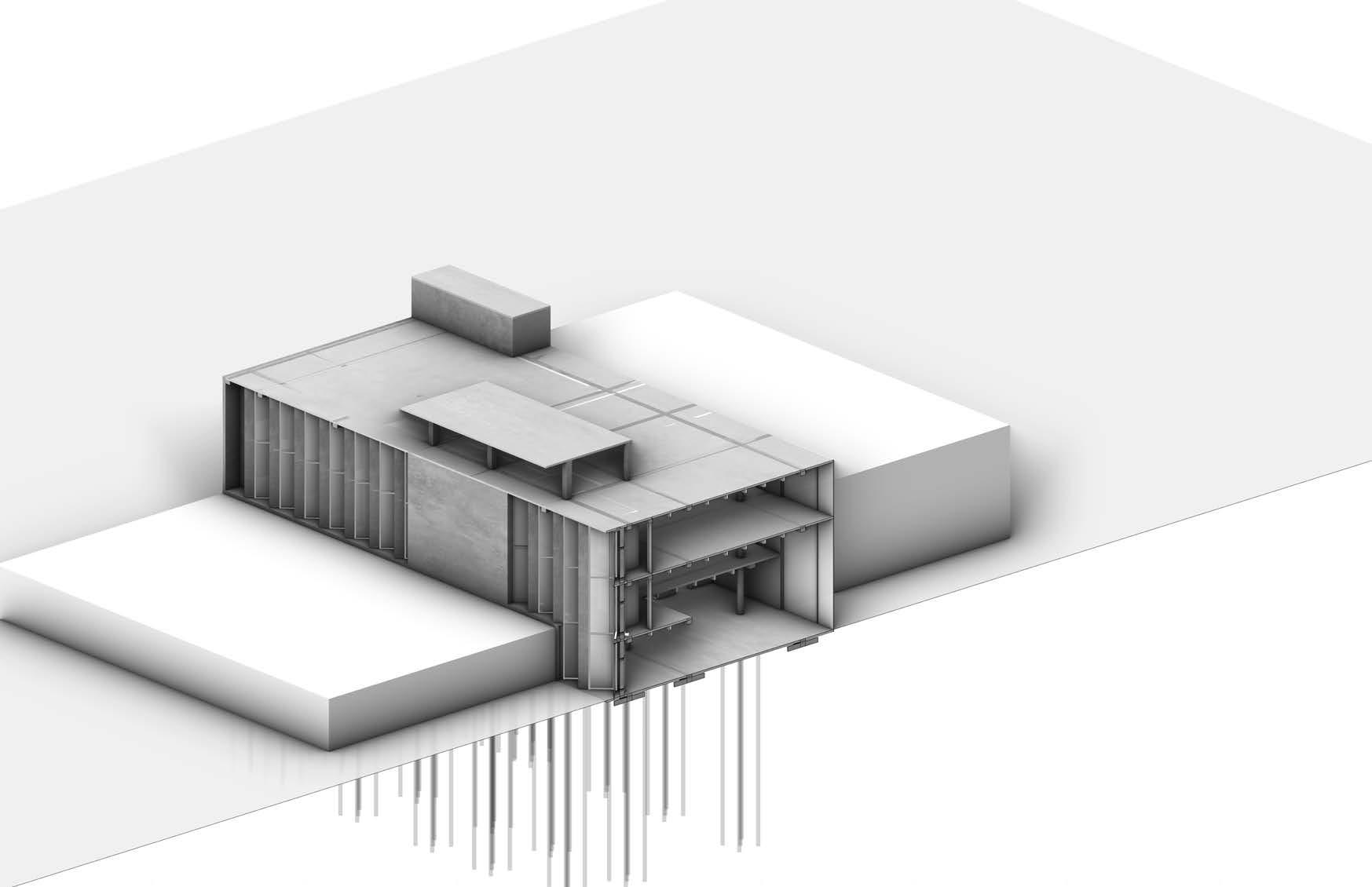
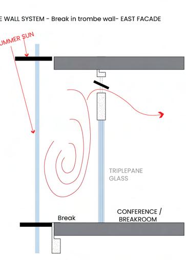
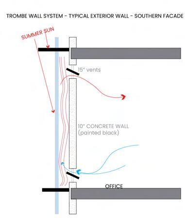
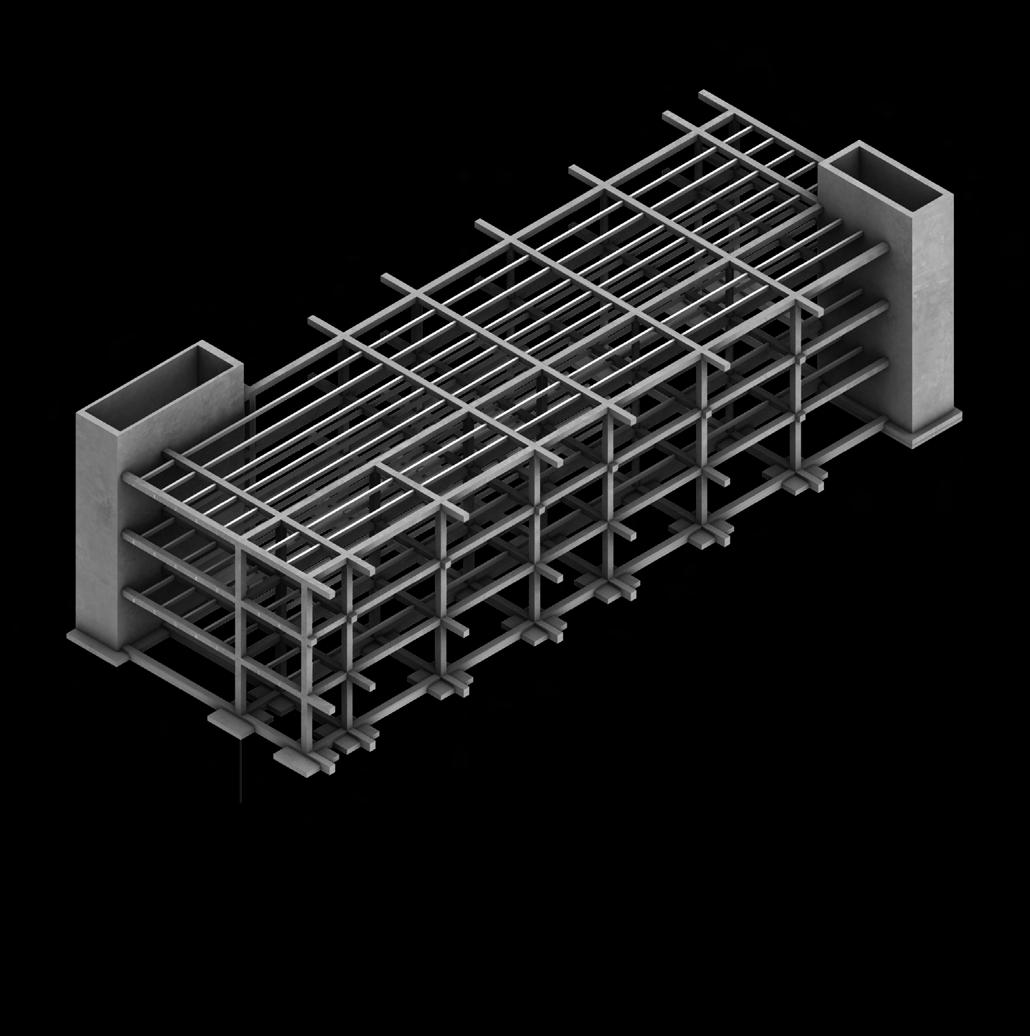
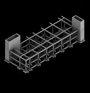
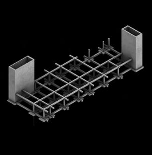
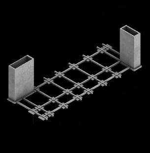
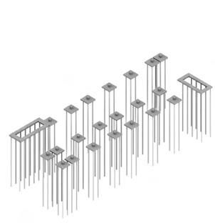
The proposed infill building will be constructed by reinforced concrete. Due to a high level of deep mushy soils, a helical pier is the recomendation for foundation. Helical piers are beneficial for this site becasue they bear in the natural soils layer below the existing fill and organic deposits. A trombe wall is benefitial in Boston when there are large swings in temperatures, specifically when the days are cold and sunny. This system prevents over heating from the south facade in the summers. The system is designed with 15” vents in a 10” concrete wall to create effective and immediate heat gain in the winters and heat loss in the summers. Overhangs installed in each floor of the trombe wall prevent summer sun and reduce heat gain in the summer.
ARCH INTEGRATED BUILDING SYSTEMS INSTRUCTORS: PHASE II 10.14.2022 TEAM 10 BOSTON, MASSACHUSETTS SHEET TITLE COVER SHEET DRAWN BY MACKENZIE SHINNICK PATRICIA RANGEL ERIC TROLLINGER ARCHI SHAH KISHORE KANDASAMY SHEET NUMBER C001 RUSSEL GENTRY MICHAEL GAMBLE HOWARD WERTHEIMER TODD MOWINSKI
solar
Passive
house with trombe wall
Additional settlement of 6” over 20 year span
Trombe wall
Plans and details
GENERAL RECOMMENDED FOUNDATION PREPERATION
Due to a high level of deep mushy soils, a helical pier is the recomendation for foundation preperation. Helical piers are beneficial for this site becasue they bear in the natural soils layer below the existing fill and organic deposits. Specifically, 4-8” diameter encased and grouted helical piers can carry building loads of up to 35 tons. The carrying capacity of natrual granular soils is 125 lbs/sqft. The friction angle can be no more than 34 degrees. Assuming grout diameter of 8”, the compressive load on each pier should be increased by 10 kips to account for down drag from compression of organic soils. Alternatively, install with permanent casing to mitigate down drag forces due to ongoing consolidation of existing fill.
PASSIVE HEATING
TROMBE WALL SYSTEM
SOLAR RADIATION EXPOSURE ON FACADES
South Facade - Highest solar exposure East Facade - Equal solar exposure to West wall,
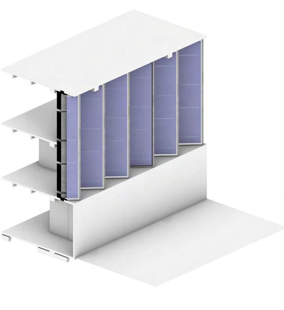
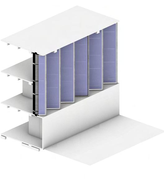
A trombe wall is benefitial in Boston when there are large swings in temperatures, specifically when the days are cold and sunny. This system prevents overheating from the south facade in the summers. The system is designed with 15” vents in a 10” concrete wall to create effective and immediate heat gain in the winters and heat loss in the summers. Overhangs installed in each floor of the trombe wall prevent summer sun and reduce heat gain in the summer.
South Facade - Highest solar exposure
East Facade - Equal solar exposure to West wall, but has a greater surface area
Trombe wall sectional isometric


pier is the recomendation for for this site becasue they bear in organic deposits. Specifically, 4-8” carry building loads of up to 35 tons. lbs/sqft. The friction angle can diameter of 8”, the compressive load on for down drag from compression casing to mitigate down drag
Passive air flow analysis
Transverse Air Flow Diagram Longitudinal Air Flow Diagram
INTEGRATED BUILDING SYSTEMS
TEAM 10: BOSTON BUDDIES BOSTON, MASSACHUSETTS Transverse Air Flow Diagram In order to provide you with an appropriate comparison for your building, we need to know how spaces in this building will be used. If your building Source EUI (kBtu/ft²/yr) 219 66 N/A Total GHG Emissions (metric tons CO₂e/yr) 229 69 N/A imperial metric print PASSIVE
ARCH 8873:
III
10” concrete wall to create effective and immediate loss in the summers. Overhangs
in each summer sun
reduce heat gain in the summer.
installed
and
Silty Clay Groundwater Elevation
3 - 6.5’ -1.5 - 2’
Trombe
PREPERATION
5”-6”
Trombe Wall on South and East Facades
83
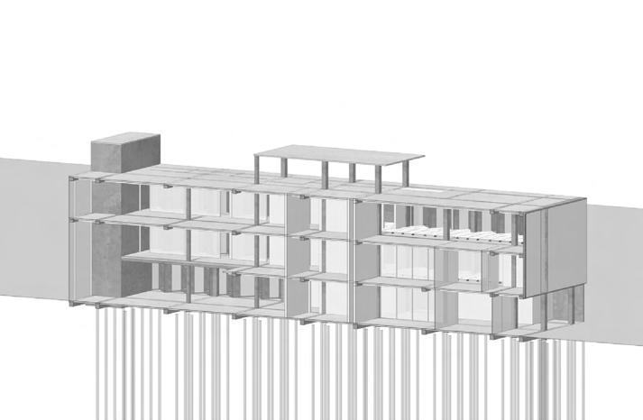
TEAM 10 BOSTON, MASSACHUSETTS SHEET TITLE LEVEL 3 FLOOR PLAN DRAWN BY MACKENZIE SHINNICK PATRICIA RANGEL ERIC TROLLINGER ARCHI SHAH KISHORE KANDASAMY SHEET NUMBER A103 1 2 3 4 5 6 7 8 9 10 11 12 13 14 15 OPEN OFFICE AREA PRIVATE OFFICE AREA STAFF LOUNGE PANTRY ELECTRICAL ROOM DATA ROOM DUCT CHASE OFFICE STORAGE STORAGE CONFERENCE ROOM COAT CLOSET OFFICE LOBBY EVENT SPACE BATHROOM PRIVATE BATHROOM LEGEND ARCH 8873: INTEGRATED BUILDING SYSTEMS III INSTRUCTORS: PHASE II 10.14.2022 TEAM 10 BOSTON, MASSACHUSETTS SHEET TITLE LEVEL 3 FLOOR PLAN DRAWN BY MACKENZIE SHINNICK PATRICIA RANGEL ERIC TROLLINGER ARCHI SHAH KISHORE KANDASAMY SHEET NUMBER A103 RUSSEL GENTRY MICHAEL GAMBLE HOWARD WERTHEIMER TODD MOWINSKI 1 2 3 4 5 6 7 8 9 10 11 12 13 14 OPEN OFFICE AREA PRIVATE OFFICE AREA STAFF LOUNGE PANTRY ELECTRICAL ROOM DATA ROOM DUCT CHASE OFFICE STORAGE STORAGE CONFERENCE ROOM COAT CLOSET OFFICE LOBBY EVENT SPACE BATHROOM PRIVATE BATHROOM LEGEND ARCH 8873: INTEGRATED BUILDING SYSTEMS III INSTRUCTORS: PHASE II 10.14.2022 TEAM 10: BOSTON BUDDIES BOSTON, MASSACHUSETTS SHEET TITLE LVL 1 HVAC PLAN DRAWN BY MACKENZIE SHINNICK PATRICIA RANGEL ERIC TROLLINGER ARCHI SHAH KISHORE KANDASAMY SHEET NUMBER M201 RUSSEL GENTRY MICHAEL GAMBLE HOWARD WERTHEIMER TODD MOWINSKI 13 6 5 10 10 9 11 9 1 2 3 4 5 6 7 8 9 10 11 12 13 14 15 OPEN OFFICE AREA PRIVATE OFFICE AREA STAFF LOUNGE PANTRY ELECTRICAL ROOM DATA ROOM DUCT CHASE OFFICE STORAGE STORAGE CONFERENCE ROOM COAT CLOSET OFFICE LOBBY EVENT SPACE BATHROOM PRIVATE BATHROOM LEGEND ARCH 8873: INTEGRATED BUILDING SYSTEMS III INSTRUCTORS: PHASE II 10.14.2022 TEAM 10: BOSTON BUDDIES BOSTON, MASSACHUSETTS SHEET TITLE LVL 1 HVAC PLAN DRAWN BY MACKENZIE SHINNICK PATRICIA RANGEL ERIC TROLLINGER ARCHI SHAH KISHORE KANDASAMY SHEET NUMBER M201 RUSSEL GENTRY MICHAEL GAMBLE HOWARD WERTHEIMER TODD MOWINSKI 13 6 5 10 10 9 11 9 1 2 3 4 5 6 7 8 9 10 11 12 13 14 15 OPEN OFFICE AREA PRIVATE OFFICE AREA STAFF LOUNGE PANTRY ELECTRICAL ROOM DATA ROOM DUCT CHASE OFFICE STORAGE STORAGE CONFERENCE ROOM COAT CLOSET OFFICE LOBBY EVENT SPACE BATHROOM PRIVATE BATHROOM LEGEND ARCH 8873: INTEGRATED BUILDING SYSTEMS III INSTRUCTORS: PHASE II 10.14.2022 TEAM 10: BOSTON BUDDIES BOSTON, MASSACHUSETTS SHEET TITLE LVL 1 HVAC PLAN DRAWN BY MACKENZIE SHINNICK PATRICIA RANGEL ERIC TROLLINGER ARCHI SHAH KISHORE KANDASAMY SHEET NUMBER M201 RUSSEL GENTRY MICHAEL GAMBLE HOWARD WERTHEIMER TODD MOWINSKI 13 6 5 10 10 9 11 1 2 3 4 5 6 7 8 9 OPEN OFFICE AREA PRIVATE OFFICE AREA STAFF LOUNGE PANTRY ELECTRICAL ROOM DATA ROOM DUCT CHASE OFFICE STORAGE STORAGE LEGEND '@ / '@ / $ $ $ $ $ '@ / '@ / $ $ $ $ " " " " " BOSTON, MASSACHUSETTS S301 HVAC Plan Suspended radiant panel Plan Structural Building Axon
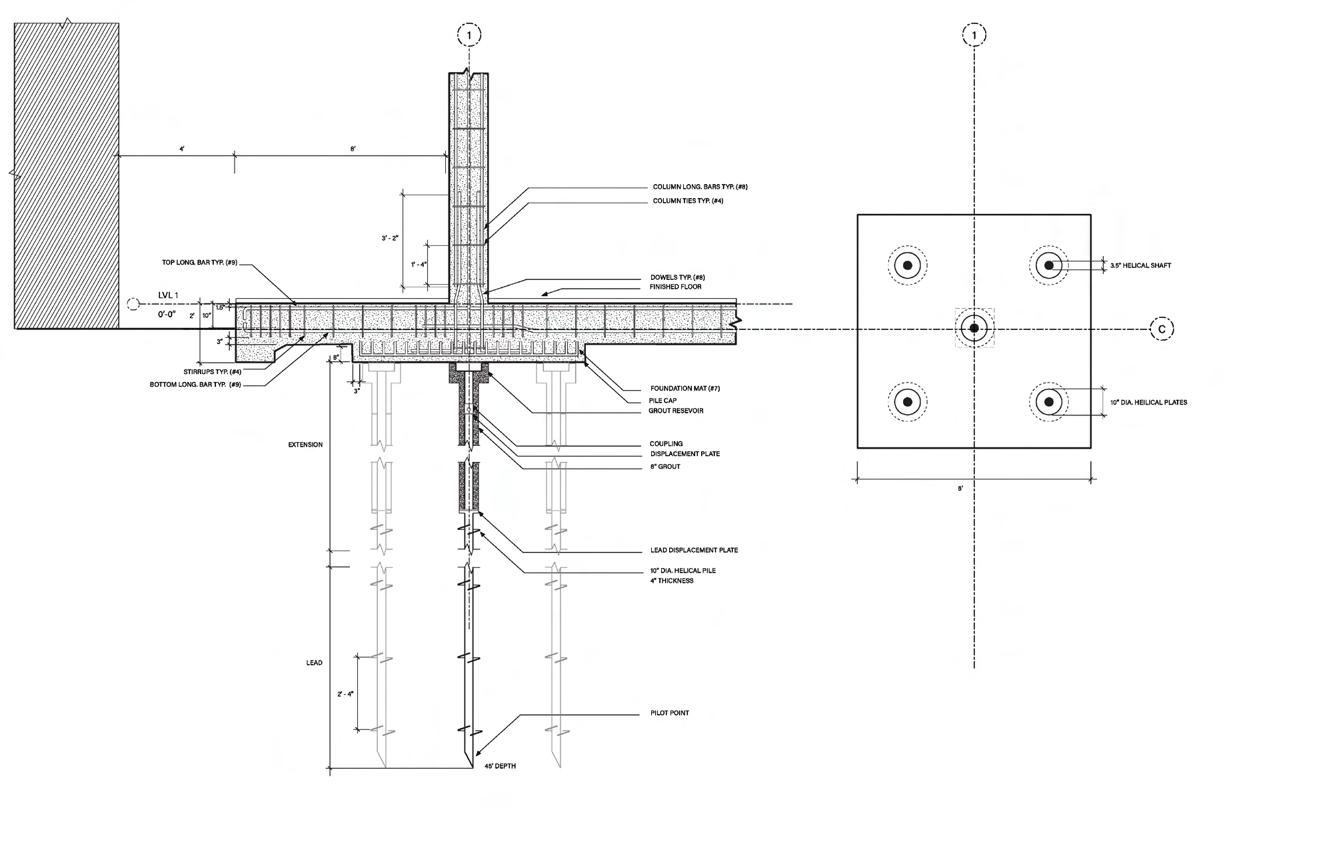
ARCH 8873: INTEGRATED BUILDING SYSTEMS III INSTRUCTORS: PHASE II 10.14.2022 TEAM 10 BOSTON, MASSACHUSETTS SHEET TITLE DETAILS DRAWN BY MACKENZIE SHINNICK PATRICIA RANGEL ERIC TROLLINGER ARCHI SHAH KISHORE KANDASAMY SHEET NUMBER A601 RUSSEL GENTRY MICHAEL GAMBLE HOWARD WERTHEIMER TODD MOWINSKI Hart, S. (2017, September 25). Slender, robust, and very tall. Architectural Record RSS. Raggousis, Maria. “Demystifying the Fly-By Curtain Wall Parapet Building Enclosure.” Building Enclosure Technical Resource CEU Education ARCH INTEGRATED BUILDING SYSTEMS INSTRUCTORS: PHASE 10.14.2022 TEAM 10 BOSTON, MASSACHUSETTS SHEET TITLE DETAILS DRAWN BY MACKENZIE SHINNICK PATRICIA RANGEL ERIC TROLLINGER ARCHI SHAH KISHORE KANDASAMY SHEET NUMBER A601 RUSSEL GENTRY MICHAEL GAMBLE HOWARD WERTHEIMER TODD MOWINSKI Hart, S. (2017, September 25). Slender, robust, and very tall. Architectural Record RSS. Raggousis, Maria. “Demystifying the Fly-By Curtain Wall Parapet Building Enclosure.” Building Enclosure Technical Resource CEU Education ARCH 8873: INTEGRATED BUILDING SYSTEMS III INSTRUCTORS: PHASE II 10.14.2022 TEAM 10 BOSTON, MASSACHUSETTS SHEET TITLE FOUNDATION DETAILS DRAWN BY MACKENZIE SHINNICK PATRICIA RANGEL ERIC TROLLINGER ARCHI SHAH KISHORE KANDASAMY SHEET NUMBER S401 RUSSEL GENTRY MICHAEL GAMBLE HOWARD WERTHEIMER TODD MOWINSKI Wall section Detail Wall section Detail Foundation Detail 85
COLLEGE
BANARAS HOUSING
STONE HOUSE
Institute of Architecture , Nirma University
LOCATION

Banaras , India
INSTRUCTOR
Prof. Vibha Gajjar | Foram Bhavsar
MODULE Related Study program
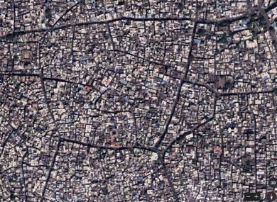
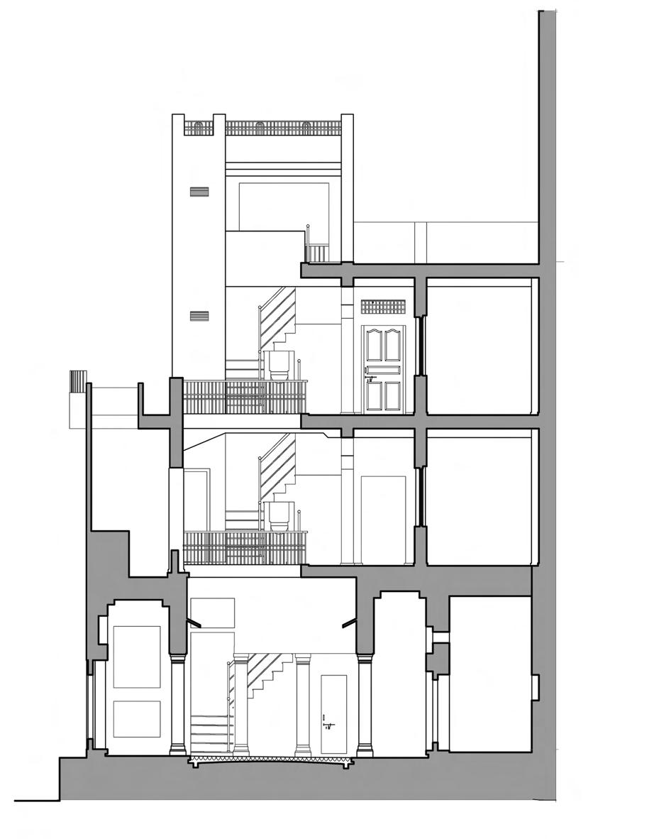
RSP program has been initiated to document and measure draw 500-year old stone houses in Banaras. The architecture of the houses in Banaras is characterized by several key features, including stone walls that are typically thick and sturdy, balconies provide additional space, common terraces that serve as shared outdoor spaces, wooden doors and windows that ornately carved, courtyards that serve as central gathering spaces, wooden staircases used in the house.
87 BANARAS HOUSING | RSP | Summer 2017
Unit Ground floor Plan
COLLEGE
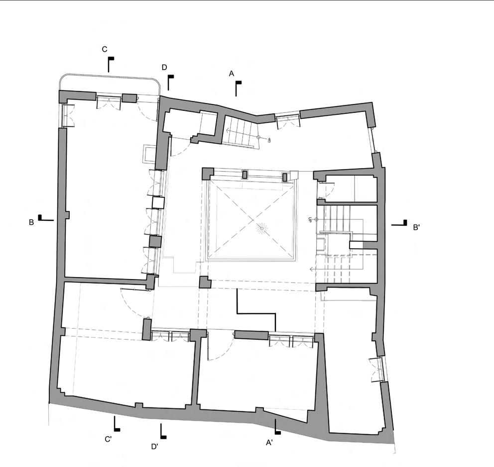
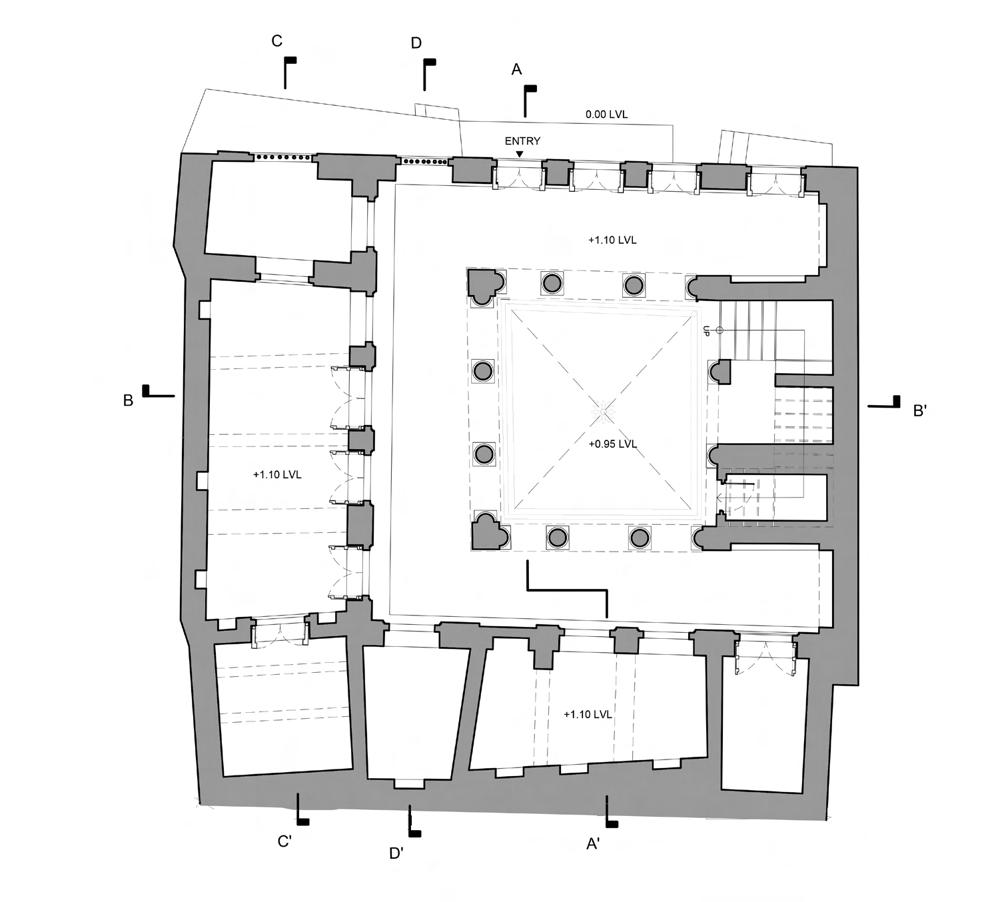
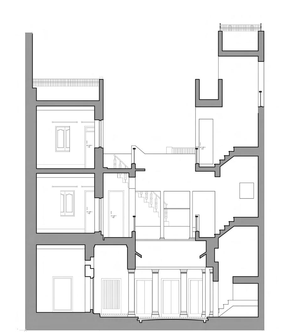
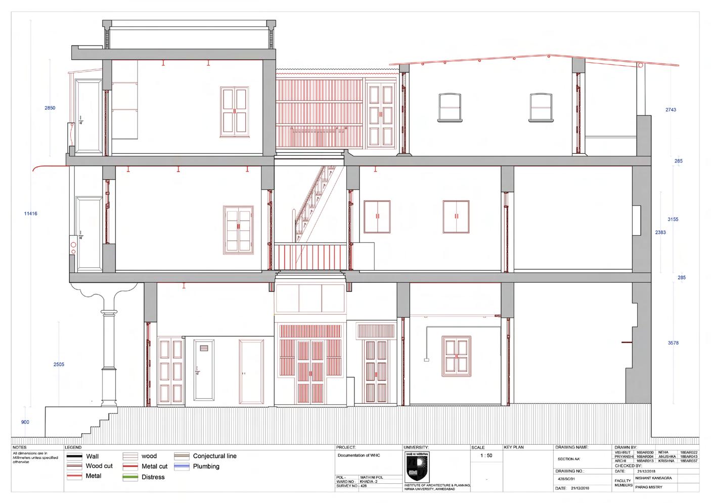
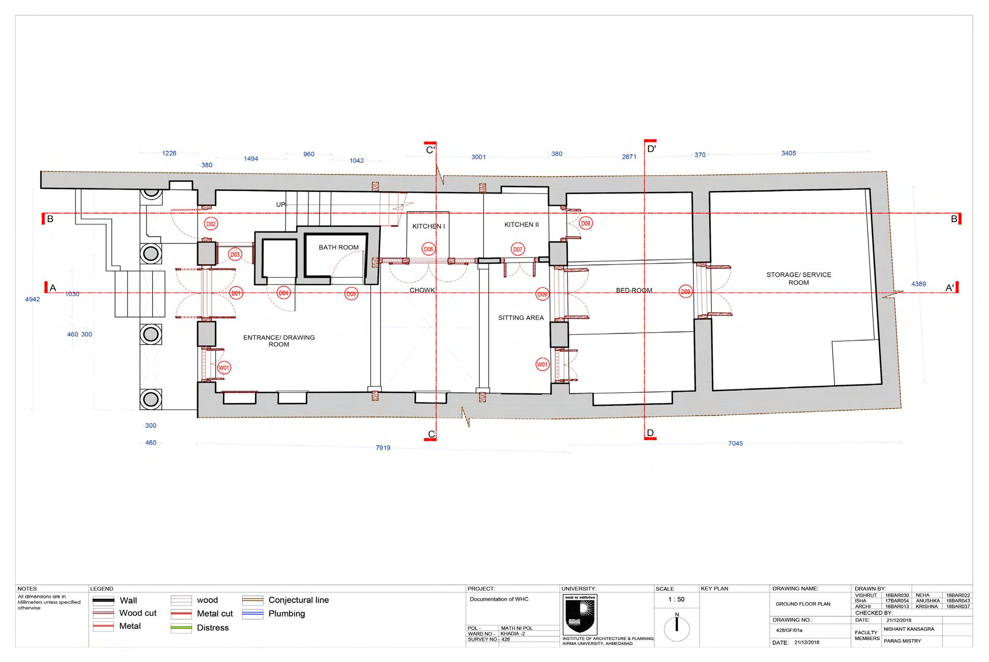
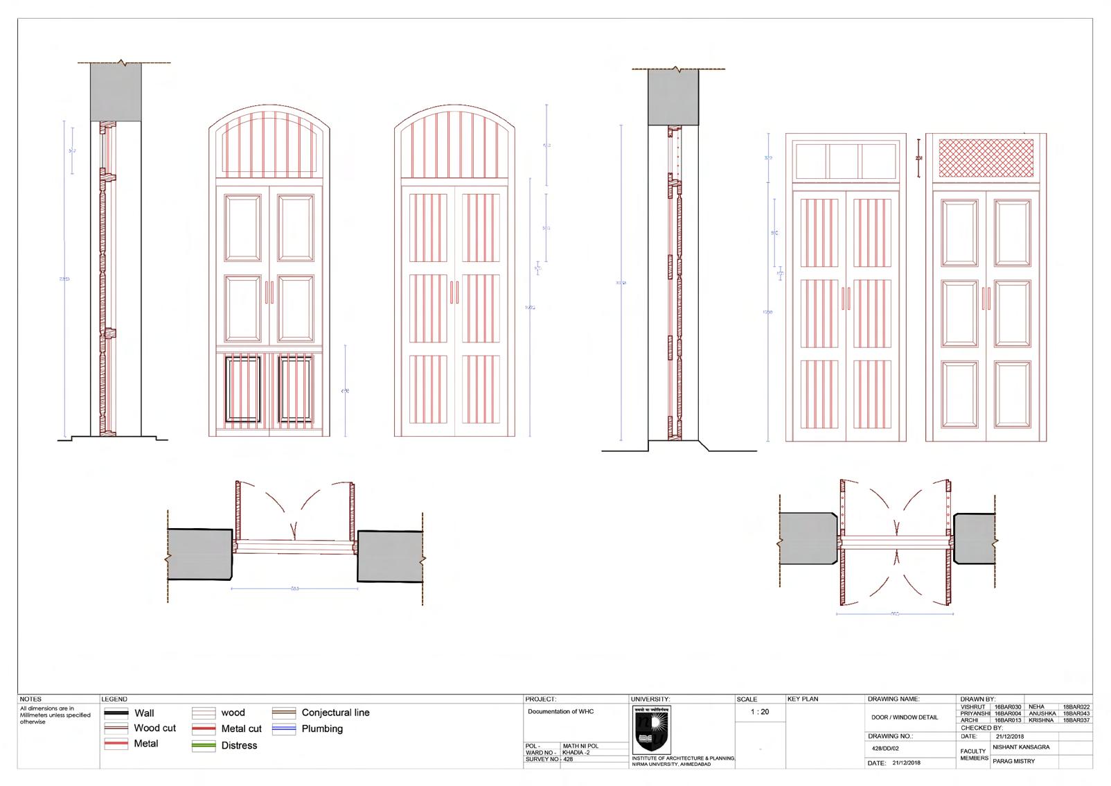
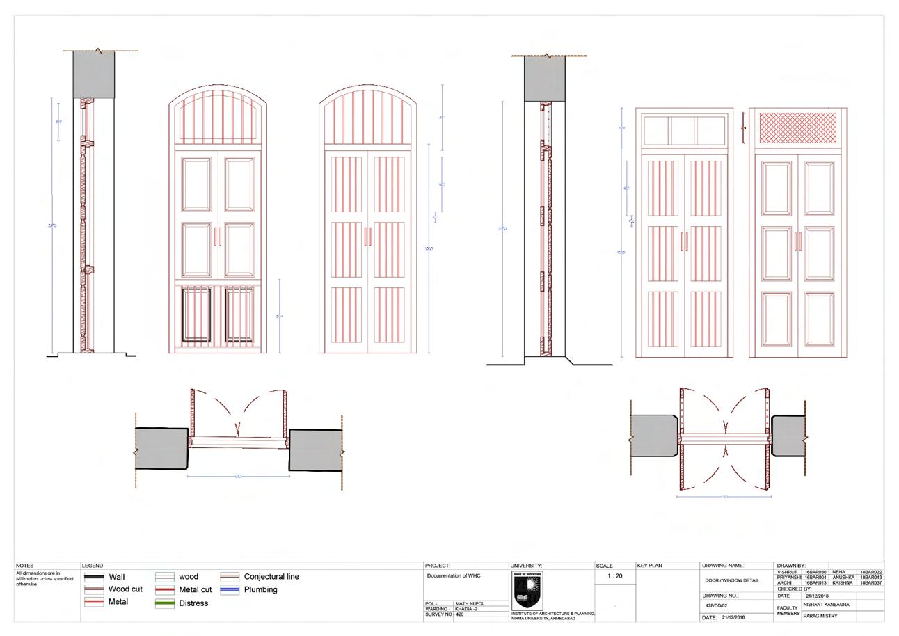
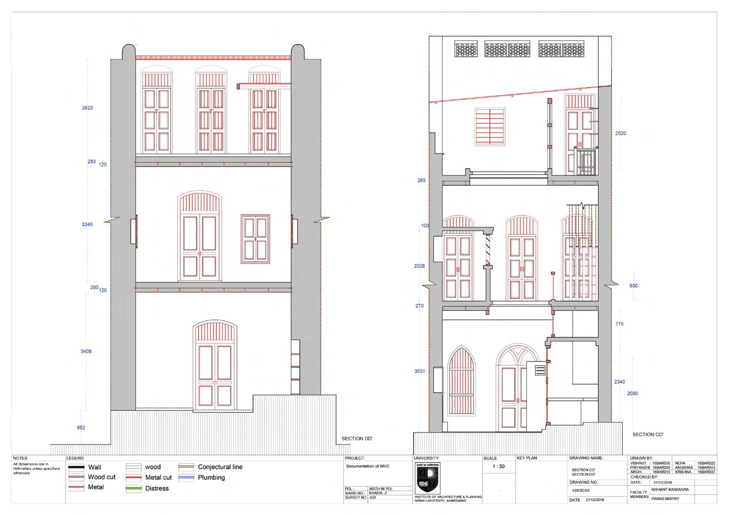
AHMEDABAD POL HOUSING
DHAL NI POL
Institute of Architecture , Nirma University
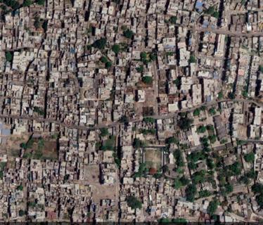
LOCATION
Dhal ni Pol, Ahmedabad, India
INSTRUCTOR
Prof. Vibha Gajjar | Foram Bhavsar
MODULE Related Study program
RSP program has been initiated to document and measure draw 200-year old wood houses in Ahmedabad Pol. Pol Architecture is a type of traditional residential architecture that is commonly found in India. The term “Pol” refers to a group of houses that are organized around a central courtyard, which is often the focal point of the architecture. These houses are typically built from mud, stone, and wood, and feature traditional design elements such as carvings, beautiful jharokhas (ornate balconies), and large courtyards.It is also a testament to the ingenuity and creativity of the builders and architects who created these structures, as well as the communities who lived in them and continue to preserve and maintain them to this day.
89
Archi Shah (+1) 4708440299 ashah667@gatech.edu Georgia Institute of Technology