
ARCHITECTURE PORTFOLIO Selected Works Meena Zahawi 2023
“A Place With No Character”
The site for my studio project was Canbury Car park. It is located in the north of Kingston, and is surrounded by two main roads, the A307 and A308. The car park is also surrounded by several general stores, such as a car garage and food delivery service store. Alongside these to the east of the site, there are further buildings. The purpose of our project this year was essentially to bring life and character to the site, due to the initial sites current ‘run down’ buildings.
01 Context
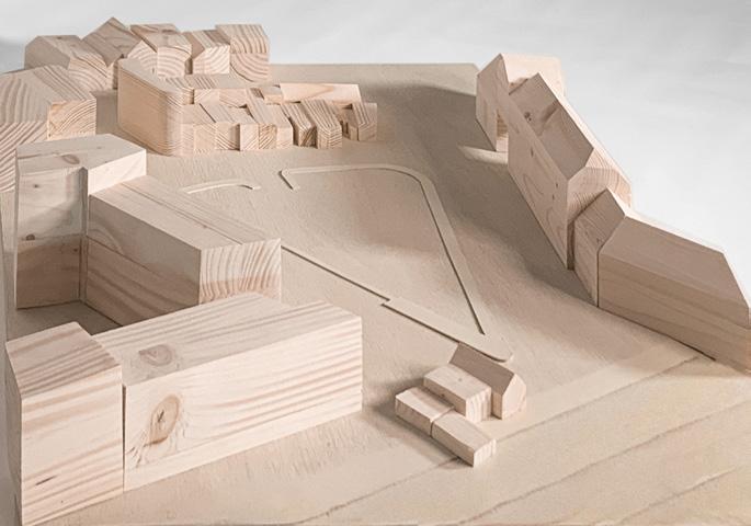
Figure1 - Wooden Site Model Of Canbury Car Park
Site Proposal
Canbury Project
02
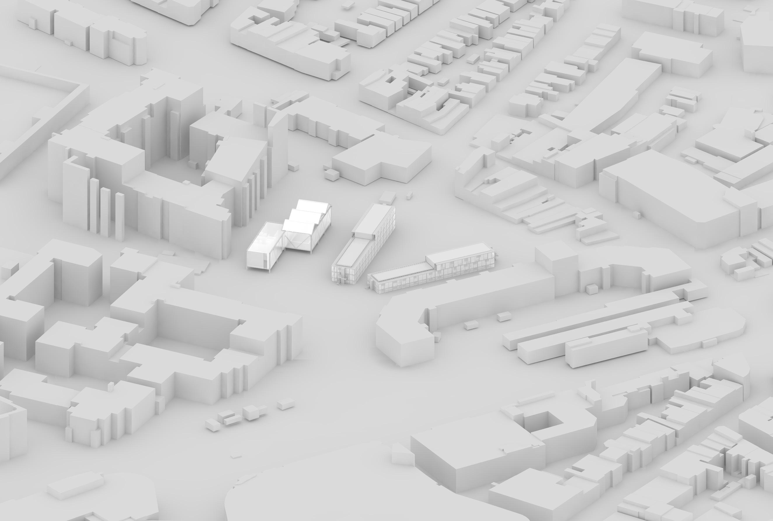
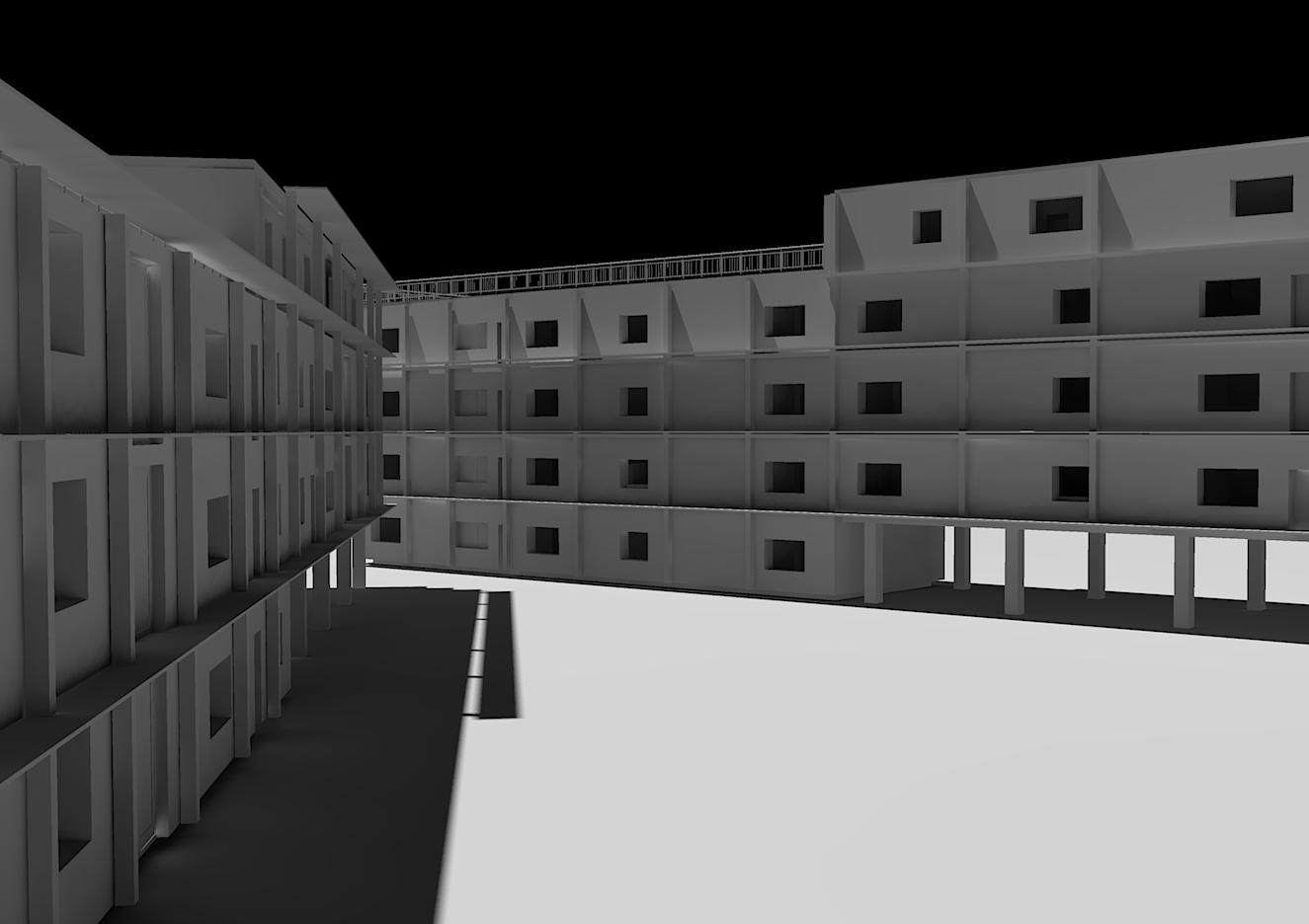
Figure 2- 3D Render, Vectorworks of Site & Proposal
Figure 2 displays a project proposal I presented in my final year. It displays two residential buildings and a community centre located on Canbury Car Park. In order to comply to the studios brief and ensure character with functionality, I had a double skin facade for my residential buildings, one being 5 storeys high, and the other 4. Moreover, in accordance to the brief, my communal space was a multi sports centre.
Site Analysis & Plan


Garden area
Play area Train Station Bus Stops

Site Observations


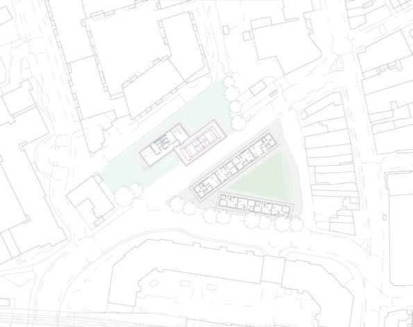
To ensure my proposal fit within the site, and covered missing aspects, I completed some analysation. The site plan on the right displays my final proposal. This includes a lake that surrounds the cmmunity centre (multi sports centre). My residential buildings fit around the site and there is green space available for the public.
 Kingston Station
Elm Crescent Bus Stop
Elm Road Play/ Open Space
Cromwell Road Bus Station
Canbury Garden
Kingston Station
Elm Crescent Bus Stop
Elm Road Play/ Open Space
Cromwell Road Bus Station
Canbury Garden
N
Seven Kings Car Park
03
Figure 3- Map Displaying Transport & Green Space
Figure 4- Site Plan, Scale 1:500


04
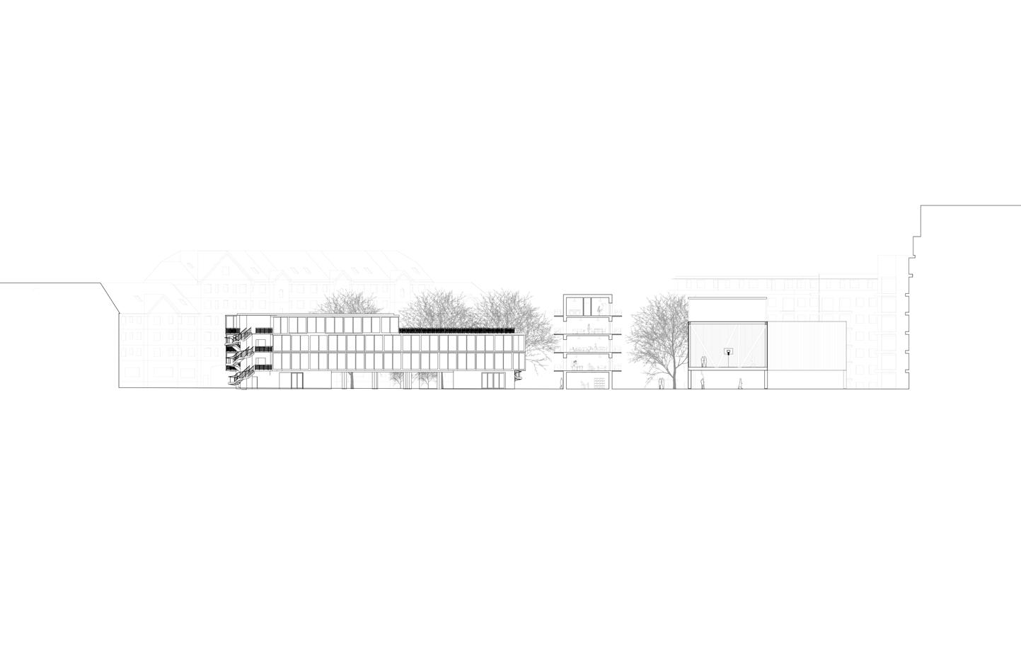
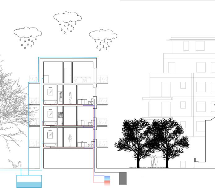
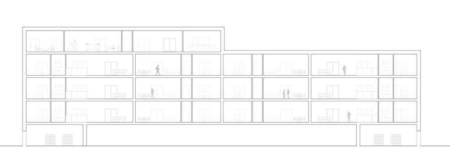
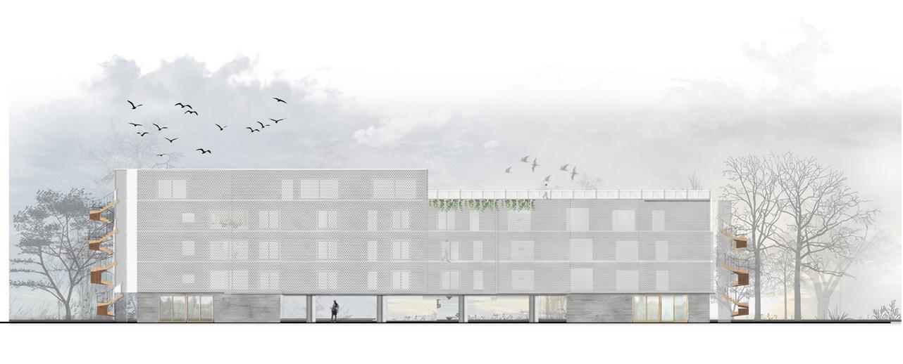
Figure 5- Site section
A- 1 Bedroom Residential building
B- 2 & 3 Bedroom Residential building
C- Multi Sports Centre
VECTORWORKS EDUCATIONAL VERSION
VECTORWORKS EDUCATIONAL VERSION
05
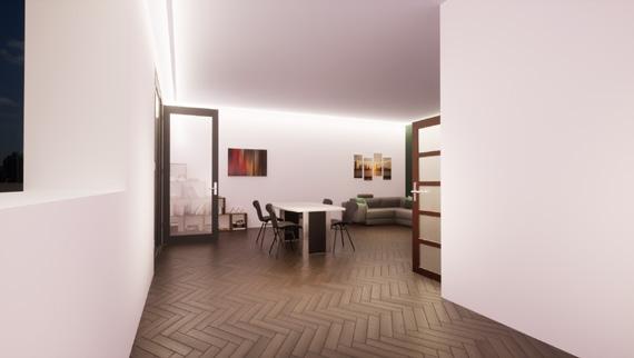
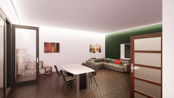
Figure 9 & 10- 3D Interior Render of 3 Bedroom Apartment, Living Room
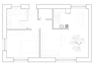
Figure 6- One bedroom Flat
Figure 7- Two Bedroom Flat
Figure 8- Three Bedroom Flat
Floor Plans
One Bedroom Plan
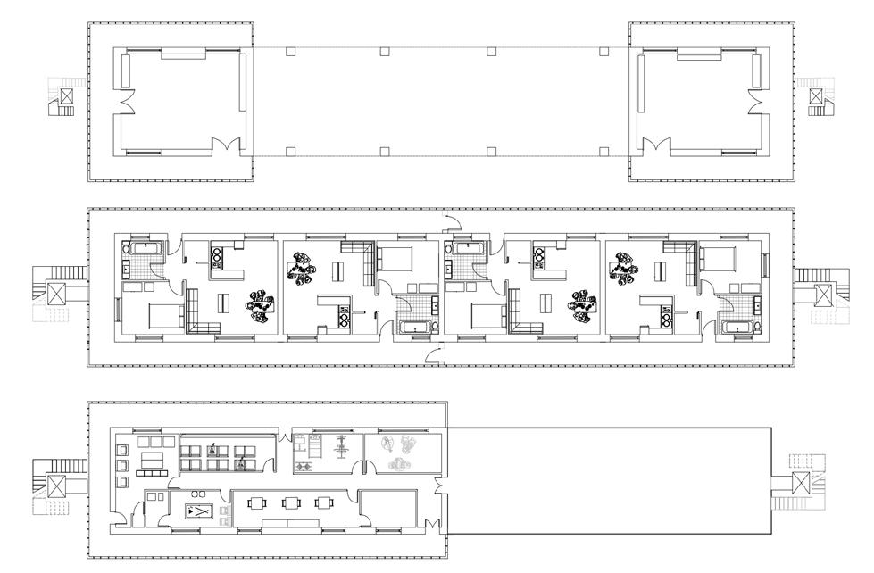
Inspired by David Chipperfields lastest project, my buildings provides character that is missing from the site. The double skin facade that is displayed in my plans is made from fritted glass and surrounds the building, ensuring privacy from the public and a private sense of space for the buildings residents. The ground floor provides access to the stairs and lifts whilst also being a space where residents are able to access their mail. The last floor is strictly for the residents, providing them with necessities (laundry room) and entertainment (cinema room).
06
Figure 11- Ground, Main and Final Floor plans of 1 Bedroom Apartment Building
Technical Drawing
Roof
Roof membrane - 1.5mm
Coverboard- 25mm
Insulation- 300mm
Air & Vapor Barrier Membrane
Structural Sheathing- 20mm
Air Cavity
Vapor Permeable AB
CLT
Middle Floor
Plasterboard - 9.5mm
CLT- 125mm
Impact Sound Insulation- 100mm
Screedboard- 20mm
Wall
Timberboards- 100x25
Timber Battens
Vapour Barrier
Air gap- 50mm
Boared- 20mm
Wood Fibre Insulation-200mm
Clt
Ground Floor
Timberboards- 20mm
Screedboard- 20mm
Insulation-200mm
Damp Roof membrane
Concrete- 400mm
07 W- 2 m B s a - mW d n a - m C M ePC - 5 m S0 m S dG u d FT mb b d- 2 mm S e b a d- 2 mm s o - 0 mm D m m m n C n e-4 0mm RR MC - mm - mm A a o e M m S a - mm A C V P m A C P - mm D b a - E e G
Vectorworks Educational Version
Vectorworks Educational Version Figure 12- Detail Section
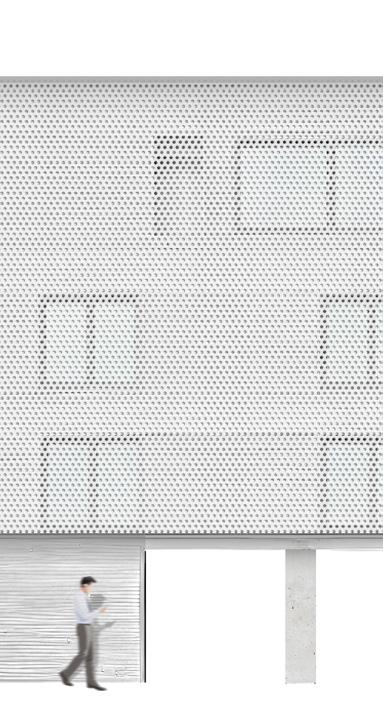
Figure 13- Elevation of Residential Building
Project Drawings
Vectorworks Educational Version
0 10m 10m 20m 30m 1:500
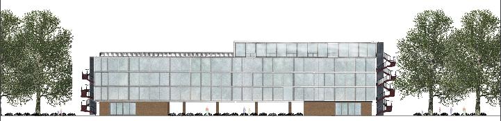
Figure 14- Elevation Drawing, Three Bedroom Residential Building
08
Figure 15- Section Drawing, on site.
Sustainbility was a big part of my project, therefore I took a passivhaus approach. Throughout, my proposal has net zero principles, reducing operational and embodied carbon emissions. Furthermore, the primary structure of my building is made from CLT. offering carbon benefits, known as a regenerative material, that is also clean in construction. Passivhaus design elements were implemented throughout, for example, triple glazed windows and thick wall insulation. We can also observe the implementation of natural features- rain water harvesting. Overall, all the elements combined create a sustainble building in line with RIBAS requirements.
M dd e F oorP as erboard- 9 5mm CLT Impact Sound Insu at on20mm Screedboard- 20mm M dd e F oorP as erboa d- 9 5mm CLT mpac Sound nsu a on20mm Sc eedboa d- 20mm RoofRoof Membrane- 1 5mm Coverboa d- 25mm nsu a on- 300mm A r and Vapo Ba e Memb ane St uctu a shea h ng- 20mm A r Cav y Vapor Permeab e AB CLT P as erboa d-9 5mm - Ex e na Layer 09
Doub e Facade- Ex e na La e G ass Vectorworks
Sustainability
Educational
Passivhaus
Figure 16- Passivhaus & Water Management Diagram


Vectorworks Educational Version Vectorworks Educational Version
Sunglight Diagram
Acoustic Diagram
Wind Diagram
Construction Diagram
10
Dead & Live Load Diagram
Figure 17- Sustainable Design
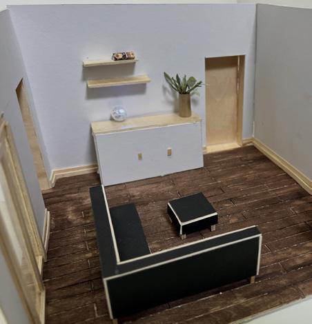
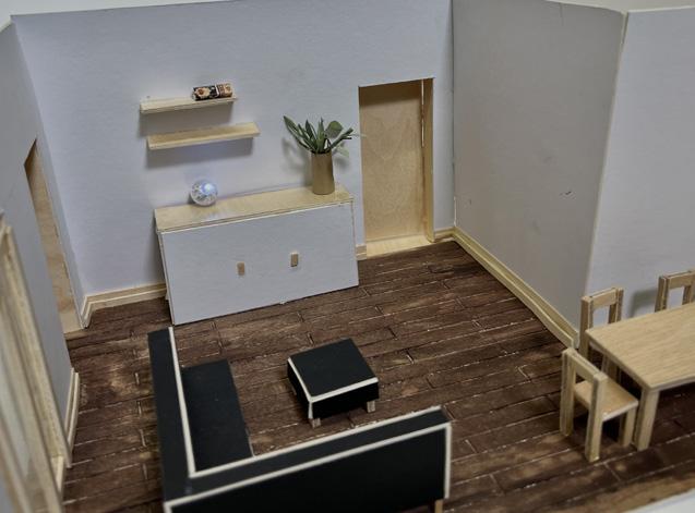
Interior model
To properly observe the space I created, I made a quick interior model from mountboard and wood to be able to comprehend the use of space. This particular model is displaying the living room and parts of the open floor plan, which would include the dining space near the kitchen. The model highlights the movement of the space created and captures the way a room could be inhabited successfully.
11
Modelling
Figure 18- Interior Model displaying space being utilised
Residential Space
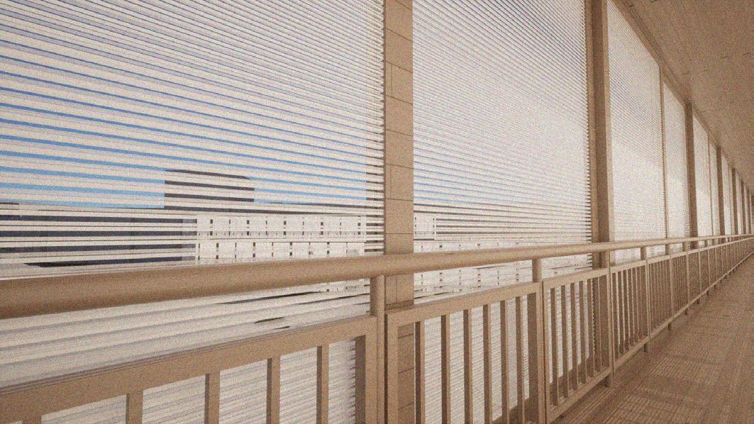
The main design of my project is perfectly illustrated through the image on the right. Using photoshop I was able to display my vision for the space outside the flats and its response to the site. The sceme introduces privacy, with the skin facades use of fritted glass, bringing modernity and development to the run down space of Canbury.
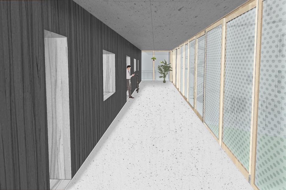
12 Interior
Figure 19- Interior Perspective Collage of Residential Buildings
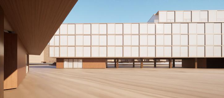
13
Figure 20- Interior Render Of Early Stages Of Proposal
Proposal Render On Site
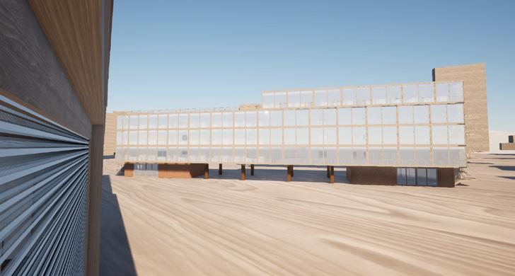
Facade & Height
The renders on the right display the residential buildings upon the site. However, the main focus of the images is its experimentation with the facade. It displays the idea of the future of canbury.
Canbury is locted in between a series of a buildings, which went from 25 storeys to 17, due to residents and councils growing concern of the impact the height of the building would have on the site. This concern impacted my overall buildings height, making my heighest building 15m. This is to ensure there were no complications and ensured maximum light capacity entering all buildings proposed and existing.
14
Figure 21- Exterior Render Of Early Stages Of Proposal
Proposal
15
Vectorworks Educational Version
Vectorworks Educational Version
Figure 22 - 3D Model of proposal on site
1 2 3 4 5 6 7 8 9 10 11 12 13 14 15
16 Construction
Figure 23- Construction Diagram Of Residential Building
Construction Process
Figure 23 displays the process of construction of the residential building. It overlines simply some steps that would be taken to erect the building. The clt is already prepared off site, and is bought to the site by a truck. The rest of the building is then constructed on the site. After the panels have all been erected and the structure is standing, the external cladding and interior finishes can begin. The timber external cladding is placed and the windows and doors assembly follow.
Final Render & Section
17
Figure 25- Elevation Drawing, Three Bedroom Building
Figure 26- Section Drawing, Three Bedroom Building
Final Community Centre Plan
Sports Centre
External wall displays the glass, with timber beams and timber structure cut through. The main sports hall serves functionally for football, basketball, tennis etc.
Vectorworks Educational Version 18
Rooms -Corridor -WC -Lounge Area -Sport Centre
-Storage -Changing
Figure 27- Structural Floor plan of multi sports centre
Year 2 Project
“Suburban Factory District”
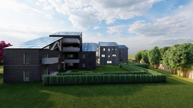
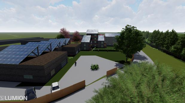
For our second year project, the site was in tolworth, a suburban area which is also a carpark. The overall aim was to create a housing scheme including one, two and three bedrooms, alongisde a factory. The objective was to also ensure there was some cohesion inbetween the factory, housing and surrounding site. Additionally, it was emphasised that our buildings must comply with passivhaus standards and be sustainable. With all these requirements from the brief considered, the result is displayed in fig 28 and 29. I utilised solar panles on both the factory and housing schemes, which created some unison amongst the two buildings whilst also opting for CLT to be the primary structure of them both. The scheme became nicely completed, moulding well within the sites landscape and surrounding buildings.
19
Figure 28- Residential Building, Housing and Factory
Figure 29- Aerial view Residential Building, Housing .and Factory Render
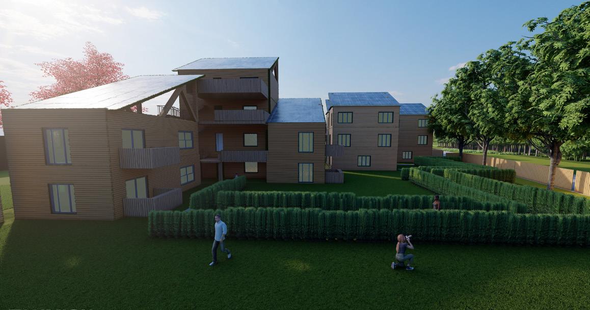 Figure 30- Close up view of housing scheme with intense light directed towards solar panels
20 Shelter Project
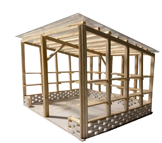
During a group project in second year, we were tasked to design a shelter for a local garden. During the group project, me and another member of the group were assigned the role of creating the model of our proposal. Here we successfully displayed our vision of the shelter. We had the idea to use the honeycomb method for the bricks, and to use timber for the rest of the structure. This was depicted through the use of balsa wood and foamboard. Our groups hardwork was displayed successfully through this model, in turn, our proposal was made and is currently standing in the garden.
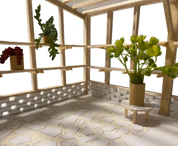 Figure 30- Shelter Model for Hogsmill garden, scale 1:20
Hogsmill Garden
Figure 30- Shelter Model for Hogsmill garden, scale 1:20
Hogsmill Garden
Meena Zahawi Architecture Portfolio Contact Information No- +44 7474307405 Email- meenazx@yahoo.com