6 minute read
Vacuum or pressure: Which is the better density control solution?


Rob Strathman, Famsun-USA Design and Engineering
Sinking aquafeed pellets allow bottom-dwelling aquatic species to quickly locate and consume their meal before it disintegrates into water pollutants or is otherwise consumed by opportunistic scavengers. Cooking and compressing the feed ingredients into sufficiently dense pellets during extrusion, however, is often challenging.
There are multiple operational techniques and pieces of hardware employed to maximize the bulk density of sinking products. However, two extruder add-on devices can provide variable density control and are commonly used within the industry. One such control system uses a mid-barrel vacuum system, while the other uses an end of the barrel pressure chamber. But the question we are frequently asked is, which is the most effective?
The underlying operating principle of both systems is to alter the melt's water vapor pressure force as it passes through the extruder die. The melt is the raw material after it transitions from a crystalline structure into a viscoelastic fluid near the extruder die. Water vapor pressure is a function of the melt temperature, which ranges from 100 to 150°C for most extruded aquafeeds. As can be found on a saturated steam chart, water within this temperature range experiences a corresponding vapor pressure of 1.0 to 4.8 bar. The water vapor pressure, not the commonly misconceived die pressure, is the driving force behind product expansion.
Therefore, it may seem logical that dense feeds would require a low melt temperature, while highly expanded floating feeds could operate at higher temperatures. Although reducing the melt temperature is a proper technique for controlling expansion, if it is too low, it often results in more significant challenges: uncooked starch and easily broken pellets. This set of counterintuitive conditions are the compelling reasons why these systems are beneficial and often necessary when extruding certain sinking feed products.
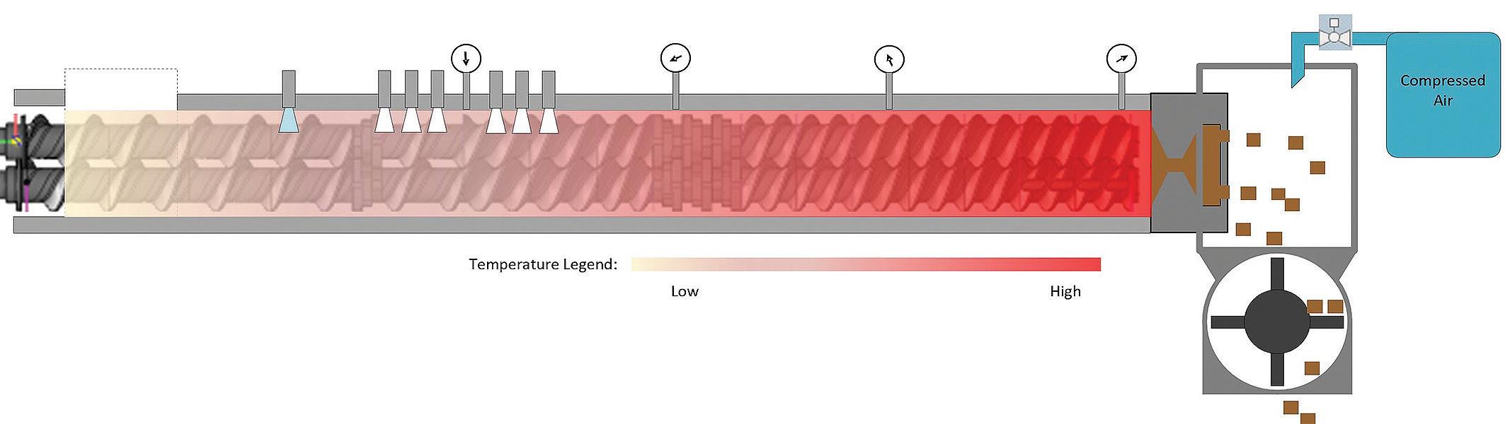
The Vacuum-Density Control System (V-DCS), see Figure 1, functions by allowing high levels of both thermal and mechanical energy to be applied earlyon in the extruder barrel. A vacuum port, located more than halfway down the barrel, then degasses or removes a portion of the high-energy water vapor from the melt. This approach first gelatinizes the starch and then cools the melt before it exits the die. The result is a denser and more durable pellet.
Pressure-Density Control Systems (P-DCS), see Figure 2, use compressed air to pressurize a die encapsulating
Figure 1. An extruder equipped with a Vacuum-Density Control System.
Figure 2. An extruder equipped with a Pressure-Density Control System.
Figure 3. Pellets from a P-DCS. Pressure: Left = None; Right = 2 bar. Bulk density: Left = 600 g/L; Right = 700 g/L.
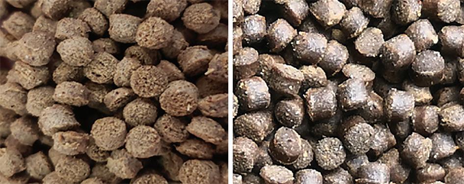
chamber to a selected level between 0.5 and 2.0 bar. The altered environment sufficiently raises the boiling point of water, preventing the moisture within the pellet from vaporizing and hindering the product's expansion. This approach also ensures a high degree of starch gelatinization, pellet durability, and an optimum density. Product photos in Figure 3 illustrate the differences in pellet porosity, texture, color and density when the pressure chamber is operating at 0 and 2 bar.
Operational considerations
The vacuum and pressure-based systems are arguably equally effective at manipulating the bulk density of aquafeed pellets. Yet, operationally, they both offer a unique set of conditions that must be considered before making a selection.
Processing moisture
A significant drawback of the vacuum systems is their tendency to pull raw material from the barrel. Hence, these systems are equipped with an integrated stuffing screw (Fig. 4) and a particulate separation system (not shown). One necessary means of minimizing the number of fine particles removed is to use large volumes of water during production. The added moisture ensures the raw materials are in a "dough-like" consistency before reaching the vacuum port, making the product more difficult to become airborne and far less likely than fines to be extracted. The typical melt moisture required when using a vacuum system is in the neighborhood of 29-33%.
Dryer energy requirements
The V-DCS operates at melt moistures that are about 3-6% greater than a P-DCS system. Table 1 compares the extrusion moisture differences between these two technologies and illustrates the impact of a 3% difference in melt moisture on the dryer's workload. In this example, the dryer’s evaporative load and energy requirement when using a V-DCS are approximately 22% greater than when using a P-DCS system.
It is important to note that in existing production lines, where a dryer is a capacity bottleneck, selecting a pressure system may also significantly increase throughputs. Potentially presenting a hefty ROI to the operation.
Screw configurations – Impact on capacity and starch gelatinization
For some manufacturers, the P-DCS's ability to produce both floating and sinking products with just one screw configuration is a significant benefit. The V-DCS, however, requires a specific screw configuration for sinking feeds, which is not optimal for floating feeds. Thus, a screw configuration change is necessary to optimize the capacity of both products.
The screw configuration required for the V-DCS is broken into two distinct sections: the cooking zone and the forming zone. The cooking zone is a short region in front of the vacuum port, while the forming zone is located between the vacuum port and the die (Fig. 1). The short cooking zone can leave some
Table 1. Impact of extrusion moisture on drying.
Extruder Parameters
Impact of Extrusion Moisture on the Dryer's Evaporative Load Add-on Density Control System Pressure Vacuum Diff.
Dry Mix Rate Steam Flow Rate Water Flow Rate Melt Moisture Kg/hr Kg/hr Kg/hr % Extruder Discharge Rate Kg/hr 4,000 320 665 27.0% 4,985 4,000 320 880 30.0% 5,200 4.3%
Dryer Parameters
Target Final Moisture Dryer Discharge Rate Evaporative Load @ Drying Efficiency Energy Required % Kg/hr Kg/hr MJ/Kg MJ/Kg 9.0% 4,000 985 2.92 2,876 9.0% 4,000 1,200 2.92 3,504 21.8%
21.8%
Figure 4. An extruder barrel with a stuffer screw and vacuum port. starch uncooked, potentially causing pellet durability issues. This becomes more problematic when making larger diameter pellets, which are more susceptible to damage caused by impact and attrition forces during handling. The P-DCS does not require the forming zone, thus typically cooks the starch more thoroughly.
Die change/Diet change-over downtime
The Pressure-DCS (Fig. 5) has an operational challenge of its own, namely the extra downtime required at each diet change-over to remove the chamber and gain access to the die. The chamber contains several additional fasteners that are time-consuming to remove and re-install, adding approximately 10 minutes to each change-over.
Selecting the right density control system
Both add-on density control systems serve their intended purpose of controlling pellet density very well, but the pressure version does offer multiple operational advantages. Yet, not all sinking aquafeeds are designed equally and there are applications where the vacuum version may be more desirable.
For example, those products requiring high levels of water stability may benefit from the higher moisture conditions required by the V-DCS, thus leveling the playing field and making the vacuum version an option to consider. Ultimately, the product design characteristics must be the first consideration when making a purchasing decision and operational factors should be a distant second.
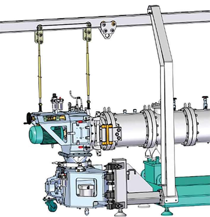

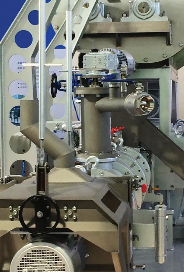
Figure 5. Famsun’s pressure-density control system.
More information: Rob Strathman
President Famsun-USA Design & Engineering, USA E: Rob.Strathman@Famsun-USA.com