PORTFOLIO
ANNA BRODERSEN brode
WORK SAMPLE 2023
Prolougue and purpose
imagine
draw think
dream work plan
play create communicate
make research
discuss analyze reason commit structure iterate specify community history materials location together place teamwork site build act — BRODE

My secret is that I am a unique creative contributor that speaks both artistic and technical languages. Not merely a designer in one field or the other, but rather a fluent communicator across the domains. This fluency allows the translation of ideas through a lens of feasibility, technicalities, and multi disciplinary skills to realize creative intent.
Every project is an opportunity to challenge conventional thinking and ignite imagination. In a world where creativity often clashes with practicality, I foster the fluidity between vision and execution. My key to execution is understanding the intricacies of construction and architectural processes. With a meticulous eye for detail, I blend the poetic with the pragmatic, ensuring every concept is not just a vision, but a practical reality.
I am not in it just for the artistry, or just for the technicalities. These are tools I draw from in the composition of meaningful places that can evoke feelings and spark curiosity. My passion is imagining spaces, and my ambition is sculpting them.
2


“Because from the fairy tale came the airplane, and the locomotive, and the wonderful instruments of our minds… it all came from wonder.” Louis Kahn
Contents 130
PERSONAL PROJECTS Mixed media projects A PLACE FOR ART Museum INSEPRABLE Competition Project - Museum TOULOUSE AMIDONNIERS Mixed Use Commercial Development 88 UNTITLED #7 Installation 114 SACRED GEOMETRY CHAPEL Model 14 MULBERRY FARM Cultural Retreat Campu 4 BI-OPEN MASSY Mixed Use Commercial Development
PROJECTS
58 FARM HOUSES Residence and guest house BLOOMING SQUARE Mixed Use Commercial Development 68 98 120 78 OASIS Adventure Park OCEAN PARK Ocean park attraction 16 4
OCEAN PARK

presentation concept schematic detailing interiors theming storyline animal area planning programming guest experience
4
[2022]
Site: Nanjing, China
Status: 2020 Targeted completion Phase 1 - 2024
With: JCO Planning + Design
Program: Entertainment campus that includes Ocean Park, Water Park, Snow Park & Retail
Overall Site: 226,260 sq.m
Ocean Park Site: 50,500 sq.m
Master Plan of Ocean Park Attraction within a larger scale mixed use, multi-attractions park known as Yanlord G84 project. Services include: capacity analysis, programming, animal areas planning, concept - design development, and construction document review.
Ticketed attraction with Entry Gateway and three themed indoor buildings/pavilions organized around an outdoor Eco Plaza. The three pavilions are:
- Tropical Pavilion (Dolphin Viewing and major Dolphin Show Venue)
- Deep Sea Pavilion (3 story Aquarium building with variety of aquarium galleries such as Sharks,
Coral Reef, Jelly Fish, Sardines and a major tank housing multi-species warm water fishes)
- Polar Pavilion ( 2 story Aquarium building with Arctic & Antarctic animal species, including Belugas, Penguins, Arctic Wolves, and Sea Lions)
5
FISH

MISSION

PROGRAMS
6
DEEP SEA
DEEP SEA L1
POLAR TROPICAL
(Above) Masterplan of Oceanpark attraction, Polar, Tropical, and Deep Sea pavilions are organized around an Eco Plaza. (Below) Level 1 plan of the Deep Sea Pavilion.
USED: Archicad, Photoshop, Illustrator
JELLYFISH GALLERY
PRESENTATION PLANS
CHILDREN’S AREA LOBBY
LEARNING LAB
SHARK AREA

7 LOBBY CONCEPT SKETCHES

8 CHILDREN’S AREA




Deep Sea Pavillion
- Children’s Area.

Divided into three “zones” connected by guest path of travel, children can enjoy deep sea themed ship zone, prop cargo deck, and sensory seeking Lucky Climber that gives an underwater view to above Jellyfish gallery.
PROGRAMS USED: Rhino, Revit, Illustrator, Photoshop, Procreate
9
CHILDREN’S AREA


A diagrammatic composition of the jellyfish, creates a mazelike passage to discover the aquariums within colorful lighting and materials.
PROGRAMS USED: Rhino, Illustrator, Photoshop, Procreate

10 2 2 1 1
Section 1 - partial
JELLYFISH GALLERY


The gallery becomes a deep sea underwater ecosystem. Experiencing the jellies as one of the jellies. Shown above is gallery 2 of the jellyfish zone.
PROGRAMS USED: Sketchup, Rhino, Photoshop, Procreate
11 JELLYFISH GALLERY
Section 2


PROGRAMS USED: Sketchup, Illustrator, Photoshop MISSION


Click to edit Master title style Sharks Wall texture Macro imagery Ceiling detail Zone 2 - Shark Hallway Partial Plan Partial Ceiling Plan Zone 2 - Shark Hallway pov1 Concrete finish Flooring. Field –Darker Grey Light Grey Bands at perimeter / parallel to walls Light Grey Border Dark Grey Field Partial Plan Partial Ceiling Plan 3D View 3D View of Shark Hallway Recessed Lighting Treatment: Walls and ceiling Shark Skeleton Interactive Table Zone 2 - Shark Hallway pov1 Concrete finish Flooring. Field –Darker Grey Light Grey Bands at perimeter / parallel to walls Light Grey Border Dark Grey Field Partial Plan Partial Ceiling Plan 3D View -Shark Skeleton Interactive Table 3D View of Shark Hallway Recessed Lighting Treatment: Walls and ceiling Shark Skeleton Interactive Table 12
(Above) Sharks area concept design development. Divider design abstracted from the teeth of sharks. Area signage concept. Ceiling and floor plans of space. 3D view of space. (Right) Plan of Sharks area.
SHARK AREA



PROGRAMS USED: Sketchup, Procreate, Photoshop
to edit Master
MISSION
– L1
Click to edit Master title style 145 SHARK TANK L2 13
Click
title style
SHARK
Main Shark Tank Front Panel
(Above) Sketch concept of Sharks main tank viewing, and 3D view of Design Development
Sharks main tank viewing. (Below) Elevation of Sharks main tank viewing. (Left) Sharks area entry wall lighting.
MISSION SHARK AREA


LEVEL 1 REFLECTED CEILING PLAN – OPTION 2 Zone 5 –Foraging Fish Lab 13 14 FISH LEARNING LAB


Tone on tone ceiling pattern to match flooring

(Left) Ceiling plan of Fish lab space, interior elevation of first round concept, detailed design development view of area. (Above), Lab hall section, detailed 3D view, concept colored hallway elevation. (Below) Concept Lab view collage.
PROGRAMS USED: Archicad, Sketchup, Procreate, Illustrator, Photoshop
7412 Manchester Rd. St. Louis, MO. 63143 USA P: 314 933 0322 I info@thejco.com Yanlord Nanjing G84 Cultural Tourism Destination Project This document contains copyright material belonging to Jco Ltd. All drawings, specifications and related documents are for use on this project only and must be returned upon request. Any unauthorized use, disclosure, dissemination or duplication in whole or part is forbidden without written consent by Jco Ltd. and will result in liability under applicable laws. Contractor must check and verify all dimensions, details and levels on the job and report discrepancies to the Architect before proceeding with work. Do not scale drawings, only figured dimensions are to be used. THIS DRAWING IS NOTTO BE USED FOR CONSTRUCTION UNTIL SIGNED AND SEALED BYTHE ARCHITECT All work will conform to provincial and federal building codes and regulations NO.DATEDESCRIPTION 50% SCHEMATIC DESIGN ( 50%) PROJECT ( ): ( ) NANJING, CHINA DRAWING TITLE CHINESE): 4/20/2022
WALL SECTION BUBBLE TANK Zone 5 –Foraging Fish Lab 18 15
FISH LEARNING LAB
OASIS AT LAKEPORT

master plan guest experience coordination programming development phasing concept detail design landscape design
16
Rendered view showing initial schematic design concept of Oasis Adventure Park
[2022]
Site: Lake of the Ozarks, Missouri
Status: Under construction
With: JCO Planning + Design
Program: Adventure park masterplan: two phases. Arcade, parking garage, multiple food/beverage areas, amphitheater, 14 rides/attractions, Observation wheel
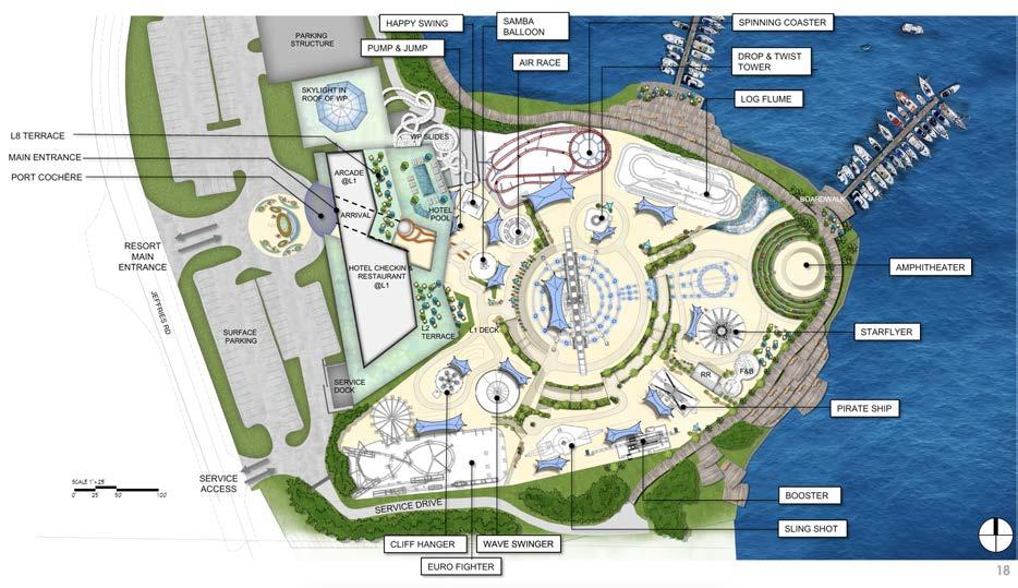
A large site with two phases. Phase one includes the contents shared here. Starting from concept, and working programmatic needs in with a geometric and site specific intensive study of the plan. An aesthetic yet highly organized composition came about. Working with the steep grades, the project is organized into layers, connected from attraction to node in wandering ramps that join the three “platforms” in which the site would be excavated.
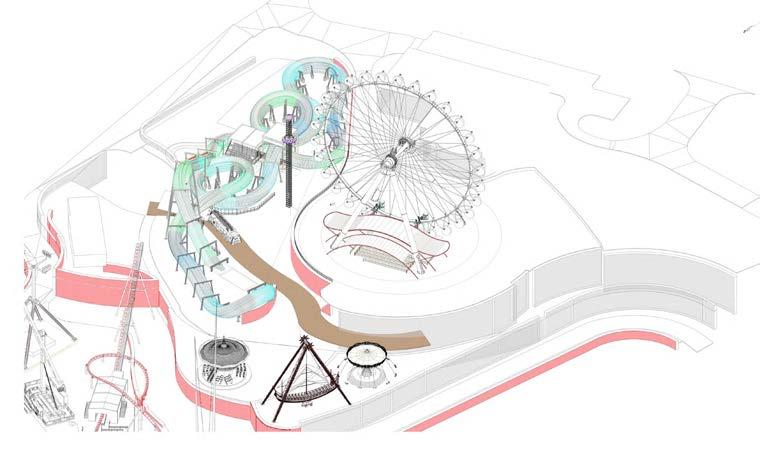
With the observation wheel centered, the guest experience of this project is aimed at defining the atmosphere by a whimsical series of attactions and to the forefront, the geography of the Lake of the Ozarks.
17


CONCEPT DIAGRAMS:


OVERALL SITE: ZONES
1. ENTRY PORTAL/ARRIVAL
2. ARCADE & RESTAURANT
3. HIGHLANDS
4. THE OVERLOOK
5. OASIS PLAZA
6. LANDING
7. BOARDWALK
Dividing the site into programmatic elements. Using the topography in unison with client program, a guest experience is organized.
PROGRAMS USED: Rhino, Revit, Illustrator, Photoshop, Procreate
705
725 18
690
720


The site zones in 4 main nodes: arrival portal, arcade, observation wheel, and ampitheatre. The plan shows an early master plan showing Oasis park and north hotel and waterpark area.
PROGRAMS USED: Rhino, Revit, Illustrator, Photoshop, Freehand drawing, Procreate
SITE: DIVIDE INTO PHASES PHASE I PHASE II IMPLEMENT CONCEPT ORGANIZE SITE BASED ON EXISTING GRADESDIVIDE INTO ZONES AROUND ELEMENTS 19


(Above) Overall site zones with attractions. (Below) Site plan with attractions and site walls. (Right), 3D view of site with observation wheel.
PROGRAMS USED: Rhino, Revit, Illustrator, Photoshop, Procreate


ZONE 1 ZONE 2 ZONE 3 BOARDWALK ZONE 2 ZONE 1 ZONE 2 YEAR - ROUND ZONE ENTRY LEVEL / UPPER PLATFORM ALL FAMILY / CHILDREN RIDES MIDDLE PLATFORM THRILL RIDES LOWER PLATFORM UPPER PLATFORM 725’ MIDDLE PLATFORM 705’ LOWER PLATFORM 685’ 03 06 02 01 04 05 07 08 13 12 11 09 10 03 02 01 04 05 07 06 lift DRAGON RUN RIDE EXPERIENCE FEATURES 01 STATION 02 LIFT 04 TUNNEL 05 HORSESHOE 06 SPEED BUMP 08 CAMELBACK 09 HORIZONTAL LOOP 10 S-CURVE 11 HIGH BANKING FLAT CURVE 12 PIT 13 FINAL CURVE 01 02 03 04 05 06 07 08 12 11 09 10 13 SHOOTOUT RIDE EXPERIENCE FEATURES 01 FLAT TURN (LOW TO THE GROUND) 02 HEADCHOPPER (BELOW DEAD END) 03 CAMELBACK (OVER STATION) 04 DIVE TURN 05 HEADCHOPPER (BELOW LIFT) 06 LARGE BUNNY HOP 07 DEAD END 01 02 03 04 05 06 07 OASIS OBSERVATION WHEEL R2 YEAR ROUND ZONE - ENTRY LEVEL UPPER PLATFORM - 725’ ALL FAMILY CHILDREN RIDES MIDDLE PLATFORM - 705’ THRILL RIDES LOWER PLATFORM - 685’ R6 R5 R4 R3 PARKING GARAGE DROP-OFF ELEVATOR ELEVATOR ELEVATOR 685’ 705’ 665’ 725’ 705’ 705’ 685’ R1 BIG THUNDER LITTLE THUNDER R10 FRISBEE THE CAROUSEL BALLOONS R7 THE PLUNGE DRAGON RUN R9 SHOOTOUT LAKESIDE SWING R11 THE PROPELLER R12 SLINGSHOT BOARDWALK BOH BOH BOH LOADING STATION LOADING STATION R8 20




PROGRAMS USED: Rhino, Revit,
May 26, 2023 OASIS AT LAKEPORT R9.01 SHEET NO. RIDE - BOOMERANG COASTER 50' 25' SCALE: 1" = 50' OVERVIEW OF RIDES R00-01 June 16, 2023 6/30/23 R1 R2 R4 R3 R6 R7 R8 R10 R12 R5 R9 21
(Above) Rendered Site plan concept phase. (Below) Site plan Design Development phase with attractions in each zone.
Illustrator, Photoshop, Procreate


22
(Left) Renderings showing overall site compilation and atmospheres within. (Above) site plan of south phase I site.
PROGRAMS USED: Rhino, Revit, Photoshop, Procreate


PROGRAMS USED: Rhino, Revit, Illustrator, Photoshop, Procreate
23
(Above) Concept plan and views of the Food and Beverage pavilion with basic views of space. Ampitheatre plan and concept rendering. (Left) Shade structure concept sketch.
View 1 View 2


PROGRAMS USED: Rhino, Revit, Illustrator,

24
(Above) Vekoma Family Coaster 3D on site, and coaster plan. (Right) render of coaster from concept phase.
Photoshop


PROGRAMS USED: Rhino, Revit, Illustrator, Photoshop


1 ROOF PLAN 1”=20’-0” MULTI-COLOR FABRIC STANDING SEAM METAL ROOF SHADE STRUCTURE AT QUEUE AREA R9.01 SHEET NO. RIDE BOOMERANG COASTER 50' SCALE: 1" = 50' DRAGON RUN OVERVIEW - COLOR OPTION 2 R08-01B R9.01 SHEET NO. RIDE - BOOMERANG COASTER 0' 50' 25' SCALE: 1" = 50' DRAGON RUN ENTRY VIEW - COLOR OPTION 2 R08-01C 25
(Above) Vekoma Family Coaster Theming concept renderings and roof plan.


PROGRAMS USED: Rhino, Revit, Illustrator, Photoshop

26
(Above) Vekoma Family Coaster colored site context section, loading station section, and plan. Coordination, landscape, operations, and placement design was a major role during the concept and detail design phases.


(Above) Vekoma Family Coaster Technical coordination drawings. Clearance checks with site walls and layout. 3D view of coaster with clearancees, section through loading building.
PROGRAMS USED: Rhino, Revit

RAILINGS TYPES LEGEND & NOTES RETAINING WALL TYPE A - QUEUE RAILING ALONG PERIMETER OF SITE, ALONG THE RETAINNG WALLS. 48”ABOVE FINISH GRADE. SEE LANDSCAPE DRAWINGS TYPE B - QUEUE LINE RAILINGREMOVABLE STANCHIONS 36” ABOVE FINISH GRADE TYPE C - QUEUE LINE – PERMANENT 36” ABOVE FINISH GRADE TYPE D - RESTRICTED AREA RAILING (RIDE BARRIER) 48” ABOVE FINISH GRADE (4’ HIGH) (1.2M) TYPE E - RESTRICTED AREA RAILING (72” ABOVE FINISH GRADE. (6’-0” HIGH) TYPE F RESTRICTED AREA RAILING (MIN. 2.0M ABOVE FINISH GRADE. (6’-8” HIGH) RIDE ENTRY SERVICE GATES INTO RESTRICTED AREAS OF RIDES. SAFETY ACCESS WITH KEYS LINKED TO THE COASTER’S MASTER KEY SEE SECTIONS A & B FOR ROOF SHADE CRITERIA * ZONE 1 ZONE 4 0.6M WIDE ZONE 3 ZONE 2 ZONE 5 1.5M WIDE SECTIONS SHOWN ON THIS SHEET ARE VEKOMA (RIDE MANUFACTURER) GENERATED DRAWINGS. THEY ARE USED FOR REFERENCE PURPOSES. ZONE 3 ROOF SHADE >3.0M SEE SECTION A ROOF SHADE <3.0M SEE SECTION B TYPE F TYPE D TYPE E RAILING TYPE D REFER TO SECTION E RAILINGS TYPE E, F REFER TO SECTION D NOT REQUIRED ROOF SHADE STRUCT. UNDER LIFT ROOF SHADE STRUCT. UNDER TRACK BEYOND 3750MM (12’-4”) MAX. HEIGHT2700 MM (8’-10”) SOFT FLOORING BELOW TRACK 422MM (1’-4”) RIDE BARRIER @ RESTRICTED AREA 1 3D VIEW 2 CROSS SECTION 1-1 3 LONGITUDINAL SECTION 2-2 27
BLOOMING SQUARE

concept form urba n site activation diagram
communicate developer radiate idealize
52
[2018]
Site: Paris, France
Status: Competition complete
With: Lina Ghotmeh - Architecture
Program: Retreat Center
Clichy-la-garenne, once an entirely wooded territory before the 19th century, is now developing in the continuity of Greater Paris. Urban expansion engulfing unbuilt spaces, this project set out to develop a balance between urbanization and the protection of green spaces. It proves how architecture can be a vector of a rapprochement between man and nature.
Water as a structuring element of the territory - the Seine river, the artery irrigating the Ile-deFrance territory, is an element that contributes to the identity of Greater Paris. Clichy-la-Garenne, at the gates of Paris, enjoys immediate proximity to the Seine which turns on itself upstream. This territory has seen ambitious projects, such as that of the portfroideville in the 16th century, and continues to be a major axis of project development, with in particular that of the seine metropolis, linking Le Havre - Rouen - Paris.
Water and green space make up the DNA of the site for this future “Blooming Square.” The art of the impressionists in the late 1800’s and relating urban expansion at the time gave depth to our research of the area and how to design a space that is truthful to the site, and the city.
53

Set on the cusp of the city, The Seine, and the various parks that surround it, the site - soon to be home of a mixed use office/retail complex - would become a centre for the area. Using the idea of connection, and growth - we created a system to bring the green spaces, and views, into the spaces in between throughout this multi level complex tower.
Paris Paris Paris 54

55


Using the concept of a tree cutting away at a box, thus creating a “link” that becomes an exterior public space, connecting the interior out, and vice versa. We then used programmatic requirements, and surrounding buildings to inform height, and began building up.

56
SITE Linking city elements Linking green space


57

58

Concept sketch showing life that would be activated through this project. Greenery would enliven the stacked masses of the building and create multi level spaces bringing the interior out and vice versa.
59

Conceptual collage showing how the existing spaces of green react to the project by radiating these tertiary spaces outward. Ultimatley showing how the site will grow from the surrounding green.
60




61
Photo renderings for the schematic design presentations. I created the 3D model for these renderings and provided auxiliary rendering touch ups after the renderers submitted them to our team. Provided here to show atmosphere and final design.
UNTITLED #7

88


[2017]
Site: East Hills Warehouse - Lawrence, Kansas
Status: Academic Project
With: Kadim Al-Asady
Program: Design Build Installation
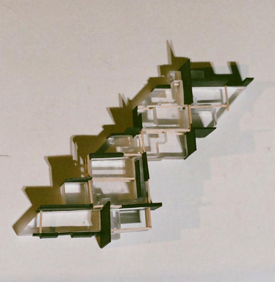
An abstract endeavor of place construction, proving an innovation in how we build for our modern world. This Studio-Build project challenges the artist’s role in design and extends the boundaries of how space is composed. It explores possible conditions we may invent from friction fit joints. And proves the inventions through the making of a 1:1 scale model. Interrelated steps stitch together a logic structure based on an imposed grid and invented rules and physical elements emerge from the geometric play. For the first time architecture is not rooted in the built artifact, but in the result of the process of space transformation. The art here lies in the design process rather than as a result of it.
89

Exhibition phamplet 90




Algorithmic engineering of geometry, and final logic structure with scale model (Above). Composition from logic structure (Below).
9 10 - SEVEN WALL ENGINEERED GEOMETRY - BOOLEAN WALL CIRCLE WALL B 36í-0î 45∞ ENGINEERED GEOMETRY - COLUMN ENGINEERED GEOMETRY - SEVEN WALL ENGINEERED GEOMETRY - BOOLEAN WALL ENGINEERED GEOMETRY - CIRCLE WALL A ENGINEERED GEOMETRY - CIRCLE WALL B 7'-0" R36'-0" R17'-6" 12'-0" 12'-0" EQ EQ 5'-9" 75° 62'-0" 12'-0 3'-0" 3'-0" 45 0 EQ 45 6'-0" 12'-0" 11'-0" 13'-6" 12'-0" 13'-0" 13'-0" EQ EQ EQ 6'-3" 6 R6'-6" 91
22 rules allowed the assembly of each component every element within this parts-to-whole system.
Fabrication - Each element is a comprised flat pack of CNC milled pieces.
Shown is the rule, the piece and its layout on wood sheet.
1 13/16" 0 25/32" 0 47/64" 0 51/64 " 2 1/2" 7/16 " 0 51/64" R0 13/64" 0 61/64" 0 7/16" 1 11/16" R0 1/4" R0 13/64" 1 25/64" 2 29/32" R0 1/4 0 29/64" 1 13/64" 19/32" 19/32" 19/32" 0 17/32" 0 7/16" 1" 0 29/64" 1/4" 39/64" 2 13/64" 2 1/2" 29/64" 2 13/64" 2 1/2" 39/64" 29/64" RULE 3.3 RULE 3.2 RULE 3.1 RULE 2.0 RULE 1.1 RULE 1.0 SHEET 6 (5X) SHEET 3 (20X) SHEET 2 (15X) SHEET 5 (2X) RULE 3.3 RULE 3.0 RULE 3.4 RULE 3.2 RULE 5.0 RULE 5.0 RULE 3.3 RULE 3.4 RULE 3.3 RULE 3.1 RULE 3.2 RULE 3.1RULE 3.0 1.5 ELUR 0.5 ELUR1.5 ELUR RULE 5.1 RULE 5.0 RULE 5.1 92
Element one section cut


Element one plan


Element one elevation
2'-0" A EQ EQ 1'-7 9/16" 1'-7 9/16" 1'-7 9/16" A A 3 3 93

The “rules”
Rules on pieces, comprise the element
94

95


96
“Untitled 7” Exhibition
1:1 Physical Model
97
Isometric showing the importance of the facade to the concept of the space
4
BI-OPEN MASSY
competition materiality program design development facade concept program refinement coordination

[2018]
Site: Massy, Île-de-France, France
Status: Design Development complete With: Lina Ghotmeh - Architecture
Program: Mixed use urban develooment: office space, retail, public plaza, two phases.
Bi Open Massy takes up a strategic place in the new Atlantis district. Located at the entry to Massy, France, it becomes an iconic element for the inhabitants of the district, the users as well as the users of the main motorway.
The building is on two levels. The ground floor is intended to accommodate tertiary activity of all kinds and the first level is devoted to offices.
The project is expressed in two phases. Totally symmetrical, the southern part rises initially. A buffer is then created between the motorway and the Atlantis district thanks to the public plaza that protects users from noise and visual pollution.
My contribution was the development of the program/spatial layout, and dialing in the facade by defining the complex facade panels. Doing material testing and physical models, the back and forth from the digital model, to physical model, was crucial in advancing the detail of the facade, and how it interacts with the surroundings, as well as the intended program, all under the conditions of client needs/engineer coordination.
5
Using the design that won the competition for the firm, I worked on developing the program to fit new parameters: client needs, keeping design integrity throughout value engineering. This included rearranging spaces to fit within a new envelope, to work out phases for which construction will take place.
RDC R+1 Roof 6
Set in industrial suburban France. A goal of the project as a commercial mix-use development project was to revitalize the area and activate the neighborhood. Program development was always driven back to site specific and community needs.
7

Facade development was a major part of the work I contributed to. Oscillating between physical models, program layout, coordination with engineers/clients, and renderings, it was a collaborative effort to dial in exactly how the envelope of the building would act.
8


Keeping the function of central cores at the ground level to orient vertical circulation as well as WC’s/storage, we divided each wing into three offices, each with a separate entrance from the street, and with access to the central public courtyard.
700m2 2 1 3 45 66 Unités 3850 m2 515 m2600 m2 600m2515 m2 700m2 PHASE 2 PHASE 1 1 3 2 4 5 6 6 Unités 350 m2 80 m2 80 m2 80 m2 PHASE 2 PHASE 1 525 m2 2 1 3 45 66 Unités 3300 m2 625 m2435 m2400 m2625 m2 375 m2 PHASE 2 PHASE 1 9




10


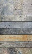
Value engineering and client changes occured post competition. Refinement was worked through a variety of mediums: massing and full architectural models were developed for analysis. A complex material palette was distilled, and how it manifests through the facade system. This process was a back and forth of material studies, physical models and digitally produced drawings/renderings.
11


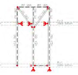

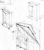
Through coordination with the team, supervisors, principal, and engineers, I worked through the detailing of the facade system panels. Working towards getting the facade system design to match the proposed concept, atmosphere, and client wishes.



12
A
13 A
2100 2130 21102120 2100 2090 2080 2080 2090 2100 2110 2120 2130 216021502140 2370 2360 2350 2340 2330 2320 2310 2300 2290 220022102220223022402250226022702280 2190 213021402150216021702180 20802090210021102120 2070 21502160217021802190 2130 2050 2100 2000 1990 2000 2010 2020 2030 2040 2050 2060 2070 2080 2090 2100 21002090208020702060 1980 1970 1960 1970 1980 1990 2000 2010 2020 2030 2040 2050 2060 2070 2080 2090 2100 2010 2020 2010 2000 20802070206020502040203020202010 2090 2100 0112 0212 2130 2140 2150 2160 21302120211021002090208020702060 2050 2050 2060 2070 2080 2090 2100 2110 2120 2130 2130 2120 2110 2100 2090 2080 2140 2130 2120 2110 2100 2060 2050 2040 2030 2020 2010 2000 1990 1990 20102000 2020 2030 2040 2080 2040 2030 2020 2020 2010 0991 3'-0" SERVICE ENTRANCE UPPER THOMAS BRANCH ROAD GATE 2010 13 THOMASUPPER RDBRANCH ILLUMINATION WAY SERENITY PLACE EVEVEVEVEV C 987654321 1017 1811 1219 20 1421 1615 EVEVEVEVEV EV EV 14
MULBERRY FARM
Portion of master site plan. Circled in red are projects described in following pages.
steel wood concrete construction details documentation specificy materials coordination

[2018]
Site: Madison County, North Carolina
Status: Under Construction
With: Cutler Anderson Architects
Program: Retreat Center
388 Acre site
12 Buildings
75 Guest Cabins
Mulberry farm is a project centered around Enlightenment. The objective was to integrate each of the buildings on the campus so deeply and intimately into the site of hundreds of acres of forest and hills. I contributed to each building in the project. Shown will be three of the buildings that had a special impact on me and my understanding of wood, steel, and concrete construction. This project was massive in the need for coordination across disciplines: architecture, landscape, structural, HVAC, contractors, clients, and ultimately within each building on the campus.
15
MEETING HALL
The Meeting Hall is the most complex building on the campus. An 8,500 square foot auditorium building with full back of house and lobby areas, as well as an outdoor deck leading to the central plaza that connects the “core” buildings: The Meeting Hall, Dining Hall, Event Center, and Fitness Center. The concept of this building at the core of the site, is a concrete “bowl” that holds the auditorium risers for seating. This system of concrete piers and slabs connect to form a bowl-like structure which supports the framing for the rest of the exoskeleton: the second floor and roof super structure from a composition of wood framing members and built up steel beams and columns. The result is a building with transparent envelopes towards the views of the pond, and solid envelopes at the back areas. This building is shown here from a mix of concept sketches, to drawings taken directly from the Construction Documentation package. The photos are all taken at midst of construction, as this is the current status of the building. Mulberry Farm (North Carolina)

16
AuditoriumGathering Hall

17
2020 2010 2000 1990 18 1 2


19
(Left) Second Floor plan, oriented towards the views of the pond, with the auxilary spaces surrounding the auditorium space.
(Above) 1, view of Meeting Hall from plaza courtyard. 2, sketched views of first floor lobby.

the details


1 20
1
(Above), the auditorium is warmed with birch plywood and select pine finishes, exposed custom steel beams, and the super structure’s concrete pillars poke through. (Right), out of the 296 details created to complete the document package, shown here are few of
describing the main intersection of concrete “bowl” connecting to the floor and roof framing systems.


21 1


Construction photos showing the concrete “bowl” with the surrounding concrete pillars that form the foundation for the rest of the super structure. (Fig. 1), shows the junction of the stepped concrete beams that support the auditorium risers.


22
1
GSEducationalVersion /Users/annabrodersen/Desktop/PORTFOLIO 2/Mulberry/_meeting hall/221011 Mulberry Meeting Hall.pln, 10/13/22, 6:34 PM 02 03 01 05 09 04 06 07 08 23 01 07 02 08 03 09 04 05 06 Foundation Steel beams Stepped concrete walls Second Floor framing Concrete platforms Steel hanger for rafters Concrete pillars Steel columns Column foundation 1
Section from Construction
Document package, cut through main staircase, showing iconic split steel colum that frames entrance to first floor lobby.
2 3 24
1


5 4 1 25
Construction photos: (top), view into core plaza from the west entrance. (Bottom), view from second floor of Meeting Hall looking out to central plaza courtyard and Dining Hall, featuring the split steel beam.
SCHOOL OF BUSINESS WISDOM
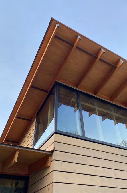
This school offers a place for the education of business wisdom. A small building with a lecture hall and two breakout classrooms, as well as small back of house and administration spaces. The building is centered around a 200 year old Oak tree deemed the “Wisdom Tree.” The entire orientation of the building is around this tree, giving the main lecture hall/ multipurpose space a view directly in admiration of this aged specimen. The building is a play of roofs on two main masses connected by an entry foyer. The building sits on the highest point of the entire site. The main lecture hall mass has a compound sloped roof - the framing members are ripped on the top and bottom to give the slope its rise along both the south and east axes. The two masses are joined by the entry space that opens up to a balcony connecting one classroom and the audtorium space, with views of the entire site. The simple wood framed building is made complex by sitting on top of its foundation to give the effect of the building sitting on a plinth. This also gave way for a crawl space to hold all HVAC equipment and ducting, which made it possible to have an open cavity ceiling exposing on the interior the glulam members. This building began schematic design in August of 2019 and I contributed to the entire process of documentation through construction administration - including coordination among disciplines as well as putting together the specifications, schedules, and handling communication between contractors, engineers, and clients. This building was the first building to start construction for the campus. Mulberry
Lecture Hall & Classrooms
26
Farm (North Carolina)

27
Final floor plan. Grading was slight since it sits on top of the site, cutting minimally into the earth.

28


Diagram shows how the massing evolved, orienting towards the Widsom Tree.

29


30
2 1
(Above), photos showing the exterior of the auditorium space’s southwest corner (left), and the interior view of the auditorium that opens up to the Wisdom Tree (right). Details show the glazing condition at the transition of 4” mullions to 6” mullions, and the window condition at the compound roof.
2 1 31 Section taken from final Construction Document package, and colored. This cut is East/West through the auditorium space.

32


33
Construction photos of interior auditorium space. (Top) exposed glulams with toungue and groove ceiling finish. (Bottom) close up of built up steel beam, see detail.


34
2 3 1
Construction photo of built up steel beam inset to the wall at the entry foyer space connecting both wings. Details (right) describe condition.
35 2 3 1
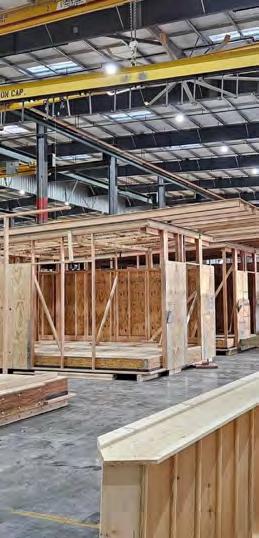
The cabins. Small one/two bed individual hotel rooms. Built up on steel columns to fit into their respective locations on the site. All 75 cabins are pre fabricated and assembled on site. Each cabin has a private entrance, WC, and private balcony. Each cabin is individually placed into the site to maximize the views and minimize the harm to the earth at each location. There are five versions of the cabins: one bed cabin, two bed cabin, ADA cabin one bed, ADA cabin two bed, and VIP cabin. The differences are slight, and mostly vary in size of cabin footprint, with the VIP cabin being the largest accomodating two beds and a sitting area. The cabins distill details from all buildings throughout the site. Birch plywood finishes, and full glazed corner to allow for the best views. Each cabin has a landing from the road, with a bridge to the cabin entrance. This allows for best placement on the site, and so the only custom construction is the bridge, varying in length and disturbing as little of the earth as possible. Mulberry
36
GUEST CABINS Pre Fabricated Guest Accomodations
Farm (North Carolina)

37
38



39
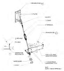
(Left) Site Plan of typical cabin. (Above) sketch elevation used in client presentations during SD, Elevation from Construction Document package, in process photo of cabin during pre-fab assembly in warehouse and upon site placement.



A B C D E F G C 40

41 11 01 02 03 04 05 06 07 08 09 10 12 13 14 15 18 16 17 19 20 26 28 29 31 30 24 23 21 22 25 27 A G B F C D E 01 13 07 19 26 02 14 08 20 27 03 15 09 21 28 04 16 10 22 29 05 17 11 23 30 06 18 25 12 24 31 Standing seam metal roof Floor framing members X-bracing Steel rod support Glazing Exterior roof sheathing Beam Exterior wall Steel beam supports Exhaust Louvres Gutter Foundation footings Studs Floor soffit sheathing Decking Roof framing members Concrete piers Handrail system Floor framing blocking Porch vertical framing Trim and blocking Steel plate Concrete abutment Porch floor framing Roof main framing Window system Steel pipe column Trim Rim boards and blocking Steel rod support Beam
TOULOUSE AMIDONNIERS

multi family mix use masterplan preserve unite community typology atmosphere elevation facade program site history
62
[2018]
Site: Toulouse, France
Status: Competition complete
With: Lina Ghotmeh - Architecture
Program: Masterplan, apartments, mixed-use, public spaces, renovation of historic chalets
~55,000m² site
3 Multi-family buildings
1 Résidence gérée
1 Hotel
8 Renovated chalets
2 Multi-purpose buildings
Toulouse Amidonniers was a competition project that spanned the last quarter of 2018. It consisted of a site north west of the city of Toulouse, France. The competition intention was to develop this site with multi-family housing and thoughtfully renovate and keep existing historic chalets. We started by doing extensive site studies and context studies of the area. Taking existing typologies of Toulouse historic architecture and using them to inform the form and atmosphere of the development.
Using the site to inform all decision making, you can see the process of how the extensive site and context studies informed the architecture, which came to be known as a jeux des toits. Using materiality and complex elevations to give personality to the dwellings, and manifest a community through the programed spaces in between.
63

64


A site emerges from existing typologies. Many Context studies were undergone to study the relationships of the buildings from the city center as the town expanded outward. This site sits on the northwest cusp of the city. The typologies of the architecture throughout the city were kept top of mind, and used to create a series of masses that may vis-a-vis and nod to the historic heart of this area.
65

66


One of the defining elements to this project was the objective to preserve the historic chalets. Using typology studies, we played with different approaches to reshaping and adapting the old: integrating multi family buildings, with a community center, and senior housing.
67


Typology studies in elevation. Facades of historic Toulouse buildings illustrated to show brick detail and hues that have evolved. This informed the project facades.

68


Protoype chalet plan and elevation in relationship the multi family buildings. Typology studies drove the iterations - varying heights and functions of multi family housing blocks are shown above.
69

70 A B C


Creating communities within the site: To preserve the identity of the small historic town, spaces throughout the site were programmed to foster community, and evolve into activated nodes.
71
A B C
SACRED GEOMETRY CHAPEL
geometry model wood contemplation space frame inhabit

106
[2015]
Site: University of Kansas West Campus, Pioneer Cemetery, Lawrence, KS
Status: Academic
With: Kent Spreckelmeyer
Program: Chapel
A place for contemplation - a chapel made by the combination of systematic lines and areas of suggested use, extrapolated from a sacred geometric figure. This concept of a chapel challenges arbitrariness by the premise of inhabiting the exact structure which composes it.
Numbers and shapes are directly connected to the atmosphere they create. It is about the experience of the structure and the spatial system it defines. This geometry chapel is proof of an ambition to make a fractal of architecture that embodies geometric applications - numeric, ideal, commoninto a larger and indefinite system of the built form. This geometry is not merely form-making but the primary conceptual tool for inhabitation.
For me, this chapel has universal and cosmic implications, but for the rest of the world the objective is perhaps pragmatic. The idea is to give light to how unusual it would be to exist within numbers and systems, and at the same time how ordinary. In every aspect of life we are inhabiting geometry, it is just the matter of how explicit, and to what degree our architecture is daring to connect us to it.
107
The chapel structure anticipates a computational approach intended to be ultimately algorithmic as well as formulaic. Constructed primitively with only wood. The application of these numeric and geometric systems makes for classic space frame construction.
(Above) Metatron’s Cube with highlighted connections used as a base for the structure.
108

109


Portion of master site plan. Circled in red are projects described in following pages.
INSEPARABLE steel wood concrete construction details documentation specificy materials coordination

112
[2023]
Site: Port of Beirut, Lebanon
Status: Competition
With: Noura Abo-Fakher
Program: Museum of Emotions
Positive emotion space
Negative emotion space
Reception
“Some of you say, ‘Joy is greater than sorrow,’ and others say, ‘Nay, sorrow is the greater.’ But I say unto you, they are inseparable.”
- Khalil Gibran.
We approached the project from a view of expressing the Lebanese condition. To put into physical form, the experience of dichotomyLiving in pain for your home, and at the same time constructing a life positively, with love and happiness. But living a life in which these two conditions are inseparable. Not able to have one without the other, and while existing within one, not being able to forget the other side is right on the other side.
113


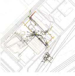
Deconstruction to Construction. The site of the August 4th, 2020 Port of Beirut blast provices the base for contrast. We build spaces of emotion from the contrast of the destroyed and the hopeful. Positive and Negative. Inventing an order from the disorder.

114
More of an exploration of the geometry of meaning rather than an intended A to B concept to deliverable process, the plan of the pavilion emerged through a free drafting techniqueletting the lines become the emotions and vice versa.


115

116


Inseprable describes the relationship between the nature of being in space. Existing within a dichotomy of positive and negative is more of a symbioctic experience than one of contrasted feeling.
117


118


119
A PLACE FOR ART
museum design site engagement urban infill detailing materiality story building gallery experience
72
[2018]
Site: Denver, Colorado
Status: Academic
With: Sean Hermann
Program: Museum - gallery spaces, classrooms, BOH, WC, Cafe, Library
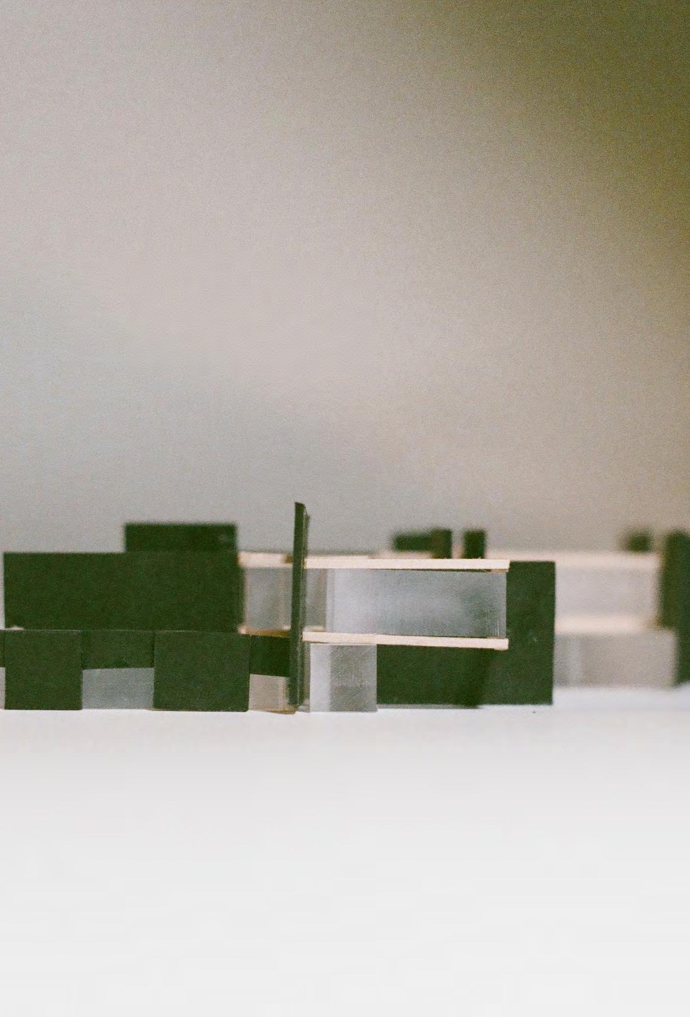
A play of walls sews together a vacant sliver of a site in an up-and-coming arts district in Denver, Colorado. An arts center for the community combines spaces to gather, observe, and partake in art and learning.
73

74


(Top) Merging of varying urban fabrics. (Bottom - left to right) Using the site to reach out. Adjacent buildings inform base nodes. Nodes become the plan.
75
CAFE MECH. LOCKERS MEN’S JAN. WOMAN’S AUDITORIUM MECH. SHAFT PREP ELEC COMMS ENTRY LOADING BOILER SECURITY GALLERY STORAGE 1 2 A B C D E 3 4 5 6 7 CC BB AA AA BB CC DD DD EE EE 1 2 Level 1 Plan | 1/16” = 1’-0” MAKER 3 STUDIO 2 GALLERY MECH. SHAFT OFFICE STORAGE ELEC ADMIN STOR.KITCHEN STUDIO MAKER 2 MEN’S WOMEN’S PATIO 1 2 CC BB AA AA BB DD DD EE EE CC 1 2 A B C D E 3 4 5 6 7 Level 2 Plan 1/16” = 1’-0” Site Plan 1/16” = 1’-0” 1 2 CC BB AA AA BB DD DD EE EE CC 1 2 A B C D E 3 4 5 6 7 76

77
Transition Public Semi-Public Private Service L1 Plan L1 Load-Bearing Walls L1 Program L1 Secondary Walls L2 Plan 78


MECH. SCREEN 44’-0” PARAPET 36’-0” LEVEL 2 17’-0” LEVEL 1 0’-0” A B C D Section AA | 1/16” = 1’-0” 79
Circulation Art/Artist Circulation HVAC & Electrical Return 80
Diagrams of circulation, HVAC & Electric, and Structural layout of load bearing walls and beam system.


81


82
1/4” = 1’ - 0” Model
photos: Gallery/flex space, Level 1, ceiling detail “stitching”

83

A B C

85 Detail A: 1 8” Steel Reinforced Concrete Wall 2 6“ Rigid Insulation 3 4” Steel Reinforced Concrete Wall 4 Expoxy Finish Floor Detail C: 1 Glass Handrail 2 Engineered Soil 3 Drainage Mat 4 Moisture Barrier 5 6” min. Rigid Insulation Detail B: 1 EDPM Roof Membrane 2 Metal Flashing, Continuous 3 Roller Shade 4 Curtain Wall Mullion 5 Butt-Joint Tri-Glazed Curtain Wall 6 36” Wide Flange Steel Framing 7 6“ min. Rigid Insulation, Sloped 8 5” Reinforced Concrete Slab 9 16 Gaug Metal Decking 5 5“ Concrete Slab-on-Grade 6 8” Rigid Insulation 7 6“ Course Gravel 8 Concrete Footing, 44” min. 9 4“ Perforated Drain Pipe 1 1 4 4 5 5 5 6 6 6 7 7 8 8 9 9 2 2 3 3 Detail A Detail B Steel Reinforced Concrete Wall Rigid Insulation Steel Reinforced Concrete Wall Finish Floor Detail C: 1 Glass Handrail 2 Engineered Soil 3 Drainage Mat 4 Moisture Barrier 5 6” min. Rigid Insulation Detail B: 1 EDPM Roof Membrane 2 Metal Flashing, Continuous 3 Roller Shade 4 Curtain Wall Mullion 5 Butt-Joint Tri-Glazed Curtain Wall 6 36” Wide Flange Steel Framing 7 6“ min. Rigid Insulation, Sloped 8 5” Reinforced Concrete Slab 9 16 Gaug Metal Decking Detail D: 1 EDPM Roof Membrane 2 Metal Flashing, Continuous 3 6” min. Rigid Insulation, Sloped 4 5“ Reinforced Concrete Slab 5 8” Steel Reinforced Insulated CMU Wall 6 4” Reinforced Concrete Wall 5 5“ Concrete Slab-on-Grade 6 8” Rigid Insulation 7 6“ Course Gravel 8 Concrete Footing, 44” min. 9 4“ Perforated Drain Pipe 6 8” Two-Way Concrete Slab 7 4“ Steel Reinforced Concrete Wall 8 6” Rigid Insulation 9 12” Air Cavity 10 6” Rigid Insulation 11 8” Steel Reinforced Concrete Wall 1 1 1 1 4 4 4 5 5 5 6 6 6 7 7 8 8 8 9 9 91011 2 2 2 2 3 3 3 3 Detail C Detail D

86

87
FARM HOUSES

residential, wood & concrete, construction, site work, filing, collaboration
42


Site: Lancaster, Pennsylvania
Status: Design Development
With: Cutler Anderson Architects
Program: Primary residence, 2 bed 2.5 bath
Guest residence gym pool
This house is for a thoughtful actor. They wanted a place that serves as a haven from the city while bringing in the chic-ness of the city to this two hundred year old land in Pennsylvania. They wanted a place for creatives and friends alike to gather, celebrate, and create together. After going through design iterations and never feeling like we “had it,” a look back at the clients program inspired a shift back to the core wishes for this place: a place to gather and celebrate and perform. A central circle driveway enters through the main house, and opens up to a dance studioturned-amphitheater orients the program around it, facing the south views overlooking a valley. [2021]
43
Knowing the client wanted a primary dwelling and a guest dwelling, the design took off from there. Setting the house on the site came down to keeping it directly south of the original residence, and orienting it with the best views of the land.
44


Program was stacked for public/private spaces, with a deck in the center. The guest wing opens up to an auditorium for the client, an actor, to have recitals - intent was to create a home as a generational gathering space for creatives alike to flourish. Left is sketch depicting foundation walls on site.
45
/Users/annabrodersen/Dropbox/ANNA'S FOLDER/SPRING 2022/PORTFOLIO/Groff/Groff.pln, 6/28/22, 9:36 PM 90 89 88 87 86 85 84 80 79 78 77 76 75 74 83 83 82 81 603 602 604 601 600 600 600' 601' 602' 596' 597' 598' 591' 592' 593' 594' 595' 610' 599' 588' 587' 586' 585' 584' 583' 582' 581' 580' 605 606 607 608 609 598 596 599.5 595 594 593 592 590 589 46 A A


(Left), floor plan used in final Design Development pricing set. (Above), east elevations of the main house, cutting through the central courtyard space and deck. Details show intersection point where concrete and wood framed walls join with glazing at a single point.
A17 PROGRESS: NOT FOR CONSTRUCTION 192 Upper Valley Rd Christiana, PA 17509 SCHEMATIC PRICING SET 8/25/21 T T T T D2 D3 2'-8" 5'-0" 2'-5" 2'-0"2'-0" 84'-6" 95'-6" 114'-10" 2'-0" 5'-0" OPEN LINE OF "CRICKET" FLSG BEYOND, SEE LINE OF FLUE 3" Ø PLUMBING VENT W/ LEAD FLSG 3" Ø PLUMBING VENT W/ LEAD FLSG FLUE CAST IN CONC 3 1 1 F.F. SECOND FLOOR RAISED F.F. FIRST FLOOR T.O. CONCRETE A13 A11 95'-0" 1'-6" 4'-6" AREA OF FILL FINISH GRADE FINISH GRADE BEYOND EXISTING GRADE FINISH GRADE AREA OF FILL AUTOMATIC SPA COVER 5/4X4 DECKING @ 3 7/8" O.C. 2X12 PT @ 12" O.C. GRADE BEYOND GRASS CRETE F.F. SECOND FLOOR 95'-0" 84'-6" AREA OF FILL LINE OF BOTTOM OF POOL F.F. SECOND FLOOR F.F. FIRST FLOOR SCALE: 1/4" 1'-0" 1 ELEVATION SCALE: 1/4" 1'-0" 2 ELEVATION 47
1 2 A A 2 1 1


48
(Above), two main and first drawn details for the gable roof with sliding barn doors integrated into the roof structure. (Right), collage showing south elevation of main house and site walls.

49
(Top), south elevation taken from Design Development package. (Bottom) section through site taken from Design Development package. Cut through living room and primary bedroom in the main house, showing the crawl space and closed cavity roof structure. Through the guest house section cuts through the gym, a two story space. The center deck holds a hot tub framed by pennsylvania feild stone stacked walls.
BIMcloud: BIMServer2.localBIMcloud Basic for ARCHICAD 24/Groff/Groff, Printed: 8/25/21, 7:26 PM T T T T T T 9'-4" 2'-0" 2'-0" 95'-6" 7'-10" 12 8 12 8 A14 FINISH GRADE BEAM BEYOND COLUMN BEYOND FOUNDATION LINE F.F. SECOND FLOOR - RAISED 95'-0" F.F. SECOND FLOOR D4 B3 9'-8" 95'-6" FINISH FLOORING RADIANT HEAT SYSTEM 3/4" PLYWD 2X8 @ 16" O.C. CLG. FINISH 3 1/8" X 10 1/2" GLULAM @ 16" O.C. ROOFING 15# BP 5/8" PLYWD 2X4 PREFAB TRUSS @ 24" O.C. INSUL VAPOR RETARDER CEILING FINISH FINISH FLOORING RADIANT HEAT SYSTEM 3/4" PLYWD 11 7/8" TJI @ 16" O.C. INSUL .006" VAPOR RETARDER 2X6 PT @ 16" O.C. BEYOND PLUMBING VENT. TYP. 12 8 12 8 A9 8" FOUN. WALL WATERPROOFING DRAINMAT WASHED GRAVEL FILTER FABRIC 4" Ø PERF. PIPE F.F. SECOND FLOOR - RAISED D4 ROOFING 15# BP 50
NOTE: PROGRESS: NOT FOR CONSTRUCTION T TT T T 8'-0" 2'-4" 9'-8" 84'-0" 114'-10" 84'-6" 95'-0" "CRICKET" FLSG, SEE LINE OF BOTTOM OF POOL FOOTING LINE 12 8 12 8 ROUGH CUT ROUGH CUT A11 A12 A10 A12.1 BEAM BEYOND COLUMN BEYOND F.F. SECOND FLOOR F.F. FIRST FLOOR WATER LEVEL T.O. CONC. T T T T T T T T T T 114'-10" 2'-6" 2'-6" 6'-10" 2'-6" 6'-10" 2'-0" 84'-6" 8'-0" AREA OF FILL FINISH GRADE LINE OF "CRICKET" FLSG BEYOND, SEE 3" Ø PLUMBING VENT W/ LEAD FLSG 3" Ø PLUMBING VENT W/ LEAD FLSG EXISTING GRADE OPEN SCALE: 1/4" = 1'-0" 1 ELEVATION SCALE: 1/4" = 1'-0" 2 ELEVATION D4 95'-0" 84'-6" 87'-0" 8" 8'-0" 3'-0" EXISTING GRADE SIDING EXT INSUL SYSTEM AIB 1/2" PLYWD 2X6 @ 24" O.C. INSUL VAPOR RETARDER WALL FINISH ROOFING 15# BP 5/8" PLYWD 2X4 PREFAB TRUSS @ 24" O.C. INSUL VAPOR RETARDER CEILING FINISH SIDING EXT INSUL SYSTEM AIB 1/2" PLYWD 2X6 @ 24" O.C. INSUL VAPOR RETARDER WALL FINISH WATER LEVEL OPEN PLUMBING VENT. TYP. MIRROR CEILING BEYOND FOOTING BEYOND 12 8 12 8 ROUGH CUT ROUGHCUT T.O. WALL 4" CONC SLAB W/ POLISHED FINISH & RADIANT COILS 2" EXTRUDED POLYSTYRENE 4" MIN. WASHED GRAVEL 8" FOUN. WALL WATERPROOFING DRAINMAT WASHED GRAVEL FILTER FABRIC 8" FOUN. WALL WATERPROOFING DRAINMAT WASHED GRAVEL FILTER FABRIC 4" Ø PERF. PIPE 2" STONE PAVER 1 1/2" SETTING BED 4" CONC SLAB WASHED GRAVEL F.F. FIRST FLOOR F.F. SECOND FLOOR ROOFING SCALE: 1/4" = 1'-0" SECTION51
PERSONAL PROJECTS

draw paint build cast sketch express create
120
Wall Mural, 79” x 90” Acrylic on Plasterboard, [2022]
[2018 - 2022]
Art, sketches, objects
The following pages include a few images of the volumes of outside work, and projects I have completed.
Abstract paintings that focus heavily on color theory and human interaction/emotions.
Objects that focus on attention to detail, form, material.
Sketches that are centered around how I view the world around me, and a snippet into my freehand drawings which are one facet to how I think.
121


An exploration into deformity of traditional furniture - by taking a simple poplar leg and apron tableand deforming it. The result - a hand and machine carved whimsical friend who I call “Table Bench.” Intended as a piano bench, or a small table... Be careful, she likes to run away!
Curly Maple with walnut buttons
122
Table Bench

123

124 Birdhouse


125
Pepe’s Garden 12” x 12” x 12”
Seattle, Washington [2021]
Plaster, pine, white oak, and walnut


126 Paintings
« 417 / 419 » 24” x 36” Acrylic on Birch panel


127
Salt on the Earth, I & II (Above) 9” x 12” Graphite, ink, watercolor on paper, (Below) 16” x 20” Graphite, ink, watercolor, acrylic, oil on canvas


Watercolor, ink, graphite on paper
128
(Top) My mother’s home in Bichmezzine, Lebanon. (Bottom) Maison Bacha, an abandoned chateau in the neighborhood of my mother’s home depictng classical arab architecture.
Freehand Drawings

Gas Works Park abandoned factory silos in Seattle, WA.
Watercolor, ink, graphite on paper
129


