Andrew Becker
PROFESSIONAL WORKS

2 andrewskis@comcast.net 802.353.1419 184 South View Path Killington, VT Professional works Syracuse University | School of Architecture | Class of 2019 To view my Design Portfolio and Creative Passions visit: https://issuu.com/andrewgbecker

3 Compiled Works Project I : 4 Columbia Proper ty Exchange Taconic - 125 WEA 5 July 17th, 2020 Project II : 10 125 West End Avenue Project III : 16 Higher Education(conf) Elevator Lobby - Looking NE (Folded Panels) Project IV : 22 11 Penn Plaza Project V : 28 Children’s Hospital(conf) CHOP NEW PATIENT CARE TEAM STATION PERSPECTIVE
Columbia Property Exchange

I
Columbia Property Exchange
315 Park Ave South, New York, NY 10010
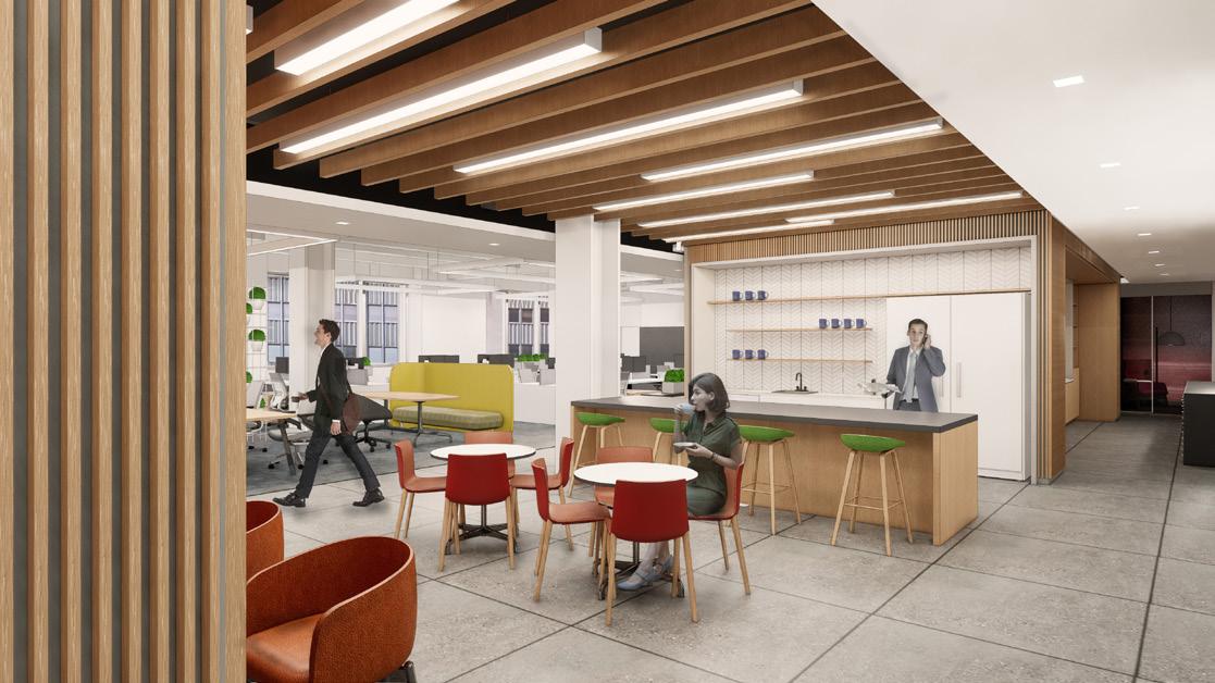
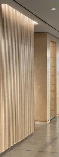
This corporate interior fit-out for the 50 person developer is designed specifically to showcase their design aesthetic to impress future clients. An important part of this project is the rebranding component that this space represents. The centralized ‘great room’ concept creates a unique environment where clients interact and view employees bewteen the open office, library, and reception to showcase the space. By flanking the great room with custom wood walls this establishes the space as the focal of the project. The intermediaty wood walls also act as the dividing point between the darker back of house program and the brigher front of house open office desks.
Size: 10,248 SQ FT
Cost Estimate. $ 3,421,000
Phase: SD through CA, construction completed
My Role: Measure and model existing conditions, construction documents, renderings, details, consultant coordination, interior finish palette, slat wall design
6


7 5 Property Trust ― 315 PAS DD Presentation #1 / January 30, 2020 Option 01 TEST FITS 315 PARK AVE S 12/06/19 1/16" = 1'-0" LEVEL 05 -Floor Plan Option 01 1 Design Concept Great Room Columbia Property Trust ― 315 PAS Great Room Concept Diagrams 8 PAS Final DD Presentation / February 25, 2020 Parti Application Library Reception Work Stations Wood Wall Design Parti Light Zone Dark Zone Intermediary Wood Walls Great Room Great Room
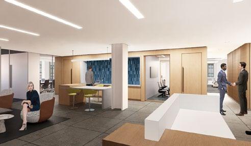
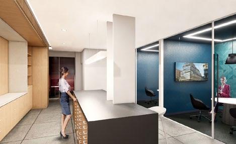
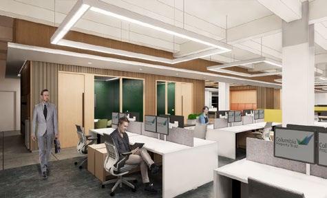
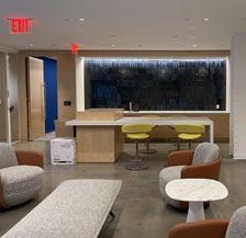
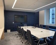
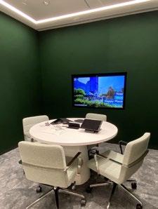
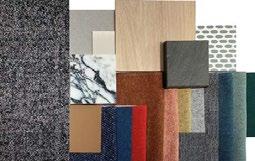
9 Columbia Property Trust ― 315 PAS Design Update/ March 25, 2020 Reception 39 Columbia Property Trust ― 315 PAS Design Update/ March 25, 2020 Library 30 Columbia Property Trust ― 315 PAS Design Update/ March 25, 2020 Open Office Look & Feel Finish palettes Final Renderings (Top: Reception, Mid: Open Office, Low: Library) Palette & Punch List Photos
II
125 West End Avenue

125 West End Ave
125 West End Avenue, New York, NY 10010
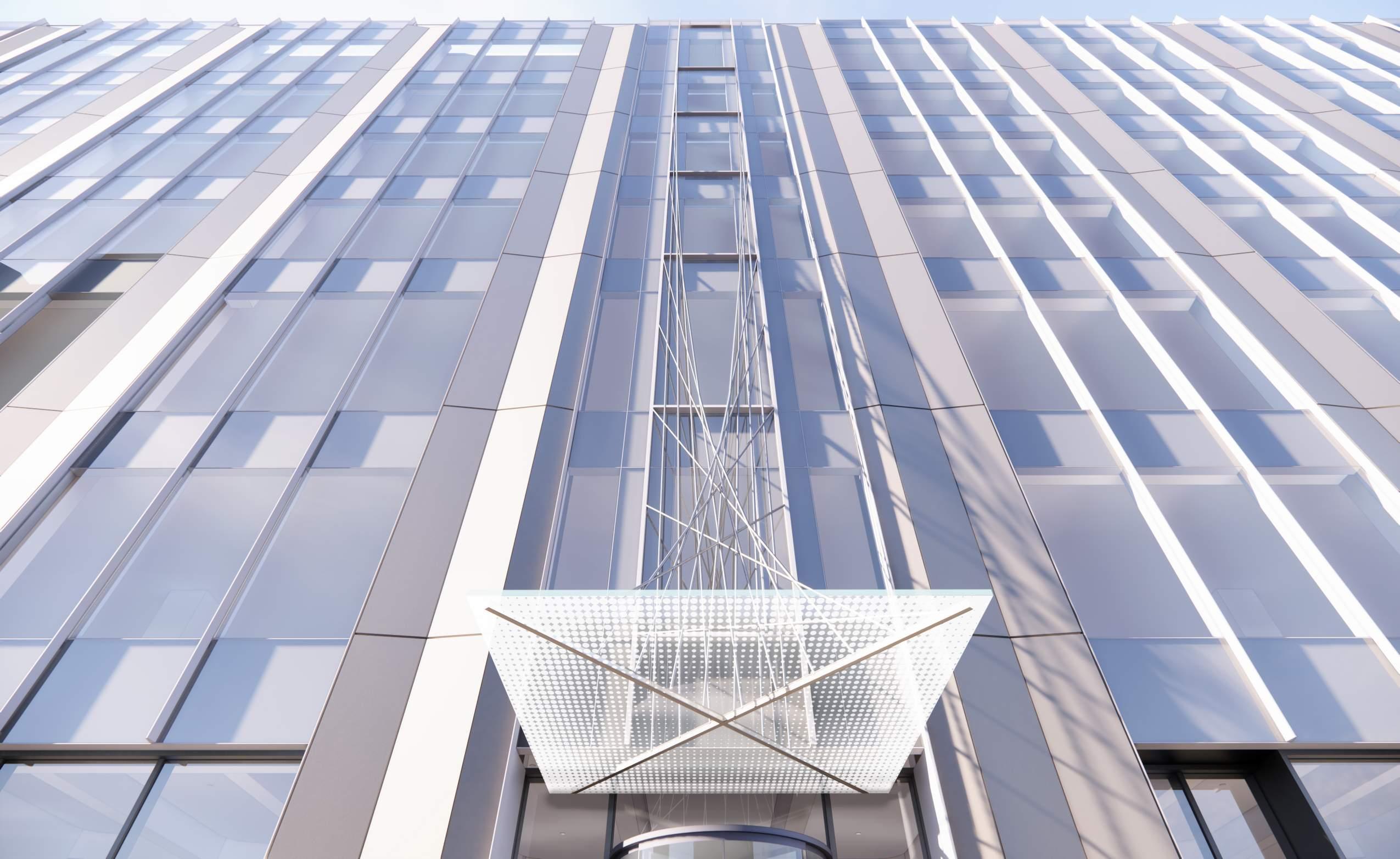
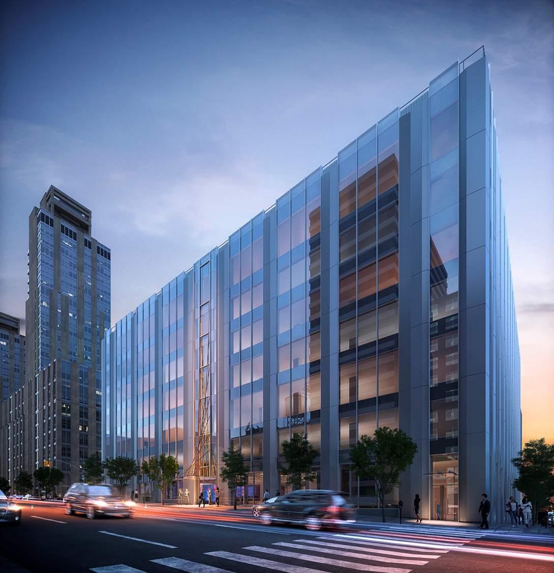
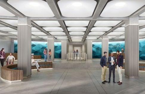
This adaptive reuse core & shell project breathes new life into a structure that was originally a motor vehicle assembly to a cutting edge science and technology research laboratory. The use of wood and stone creates a warmer, more elegant entrance. While soft lighting on organic curves and color remove the baron stereotype from science and technology research laboratories. Designing this exciting and colorful lobby is vital to attracting future tenants. On the exterior large spandrel glazing adds a modern touch and allows light to penetrate deep into the space.
Size: 353, 487 SQ FT
Cost Estimate: Approx. $ 110,620,000
Phase: SD through CD
My Role: Zoning lot line, alteration-I permiting, lobby design, roof layout, demolition set, engery analysis set, slab edge, site plan, renderings, details, code compliance, consultant coordination
12
Ceiling Elements
FINA F24D
Ceiling Elements


FINA F24D
FINA F24D


Lighting

LOBBY / GENERAL AND ACCENT LIGHTING
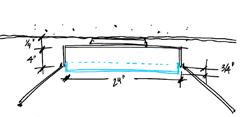
Curved Wall Detail


13 BLOCK 1171 LOT 62 MASONRY BLDG. (33 STORIES) ADJACENT BUILDING PARKING BLOCK 1171 LOT 60 MASONRY BLDG. (7 STORIES BR FACILITY PARKING ENTRANCE/EXIT PM WEST END AVE. WEST 66TH STREET 80' (WIDE STREET) 100' (WIDE STREET) EXISTING PARKING METER EXISTING SIDEWALK VAULT EXISTING STREET VAULT FDC FDC NEW FIRE DEPARTMENT CONNECTION EXISTING FIRE DEPARTMENT CONNECTION LIMIT OF CONSTRUCTION ADJACENT BUILDING OVERHANG RAISED CONCRETE PAD STAIRWAY EXISTING CURB CUT FDC NEW FIRE DEPARTMENT CONNECTION EXISTING CURB TO REMAIN EXISTING CURB CUT EXISTING BIKE RACK EXISTING STREET LIGHT EXISTING TREE, TYP FIRE COMMAND CENTER PROJECT LIMIT LINE PROJECT LIMIT LINE PROJECT LIMIT LINE PROJECT LIMIT LINE NEW CONCRETE SIDEWALK OR PAVING EXISTING ADJACENT BUILDING ARCHITECTURAL SITE PLAN LEGEND PM PARKING METER TO REMAIN FIRE HYDRANT TO REMAIN NEW FIRE DEPARTMENT CONNECTION LANDSCAPE PLANTER PAVEMENT STRIPING N TRUE NORTH BLOCK 1171 LOT 60 W 66TH ST W 64TH ST RIVERSIDE BLVD WEST END AVE SHEET NUMBER ISSUE CHART KEYPLAN PROJECT LANDSCAPING TITLE STAMP DOB APPROVAL DATUM NOTE: LEVEL 0'-0" = 28.27' NAVD88 A-090 ARCHITECTURAL SITE PLAN 125 WEST END AVENUE © 2020 Perkins & Will 111 8TH AVE, SUITE 1500, NEW YORK, NY 10011 125 WEST END AVE. NEW YORK, NY 10023 125 WEST END ASSOCIATES, LLC ISSUE FOR CONSTRUCTION 11/13/2020 PERKINS & WILL 1315 PEACHTREE ST NE, ATLANTA, GA 30309 SH TBD 031844.000 JC .00 Page 26 Of 124 ARCHITECTURAL SITE PLAN ISSUE DATE ISSUE FOR PERMIT10/30/2020 ISSUE FOR CONSTRUCTION11/13/2020 10
SHIELDING A Flush Satine Lens AL Drop Satine Lens AR Regress Satine Shielding pg. 2 FIXTURE OPTIONS AM Antimicrobial GMF Slow Blow Fixture Options pg. 4 DRIVER PL2 Advance Xitanium EE1 - eldoLED ECOdrive ES1 eldoLED SOLOdrive LH1 - Lutron Hi-lume L51 Lutron 5-Series OL2 Osram (1%, OL4 Osram 347v ND Non-Dimming Driver pg. 3 When specifying SOURCE cables, JB = connects Circuit (E), cannot be Specifications and dimensions Designed in Denver, • Aluminum • Aluminum formed white • FINA offered • ETL Listed Maximum • Lift and shift • Buy American Key Features F24DSHIELDING Specifications and F24D_SUSPENDED_SPEC_AUG2020 Designed in Denver, White virgin Ordering Code A Flush Satine Shielding • Specify either • Longer lead-time Source: White Custom OutputCL_ _ _ _ _ CW_ _ _ _ _ 80 CRI 830LO 830MO 830HO 835LO 835MO 835HO 840LO 840MO 840HO 90 CRI 927LO 927MO 927HO 930LO 930MO 930HO 935LO 935MO 935HO 940LO 940MO 940HO Specifications and dimensions F24D_SUSPENDED_SPEC_AUG2020 1 Single E Emergency N Night Circuiting • Select fixture circuiting • Some FINA configurations PL2 EE1 EE2 ES1 ES2 LH1 L51 OL2 OL4 ND U Universal 1 120 2 277 3 347 Designed in Denver, AC3___JB 3 AC cables to fixture AC3___ST 3 AC cables to fixture • The canopy can the ceiling for a • Standard kit can Flush canopy installation Canopies Mounting Aircraft cables and box or structure Canopies and pendants black depending Voltage Driver • Some FINA configurations with factory • Standard Driver • Driver Lifetime: • For more Driver at pinnacle-ltg.com SST 1/4" PLATE FRAME LINEAR LED LIGHT 1' - 0" 05-CFM FLANGES INTERCONNECTED BETWEEN FACETS FOR RIGIDITY 1/2" LEVEL 01 16' - 0" 1" 06-WPN-01 WOOD PANEL 6" 2" 06-WBM-01 METAL WALL BASE 06-SHT-02 1/2" PLYWOOD 03-PCF-11 POLISHED CONCRETE TOPPING 1' 0" 05-CFM FLANGES INTERCONNECTED BETWEEN FACETS FOR RIGIDITY 05-DFM-14 SST 1/4" PLATE FRAME 06-WPN-01 WOOD PANEL 05-DFM-14 SST 1/4" PLATE FRAME LINEAR LED LIGHT 1' - 0" 06-SHT-02 1/2" PLYWOOD 05-CFM FLANGES INTERCONNECTED BETWEEN FACETS FOR RIGIDITY 1" 1/2" LEVEL 01 16' - 0" 1" 06-WPN-01 WOOD PANEL 6" 2" 06-WBM-01 METAL WALL BASE 06-SHT-02 1/2" PLYWOOD 03-PCF-11 POLISHED CONCRETE TOPPING 1' - 0" 05-CFM FLANGES INTERCONNECTED BETWEEN FACETS FOR RIGIDITY 05-DFM-14 SST 1/4" PLATE FRAME Taconic - 125 WEA November 30th, 2020 4” (101.6mm) 21-15/16” (557.2mm) 4-1/4” (108mm) SHIELDING SOURCE1 MOUNTING2 VOLTAGE A Flush Satine Lens AL - Drop Satine Lens AR Regress Satine Lens Shielding pg. 2 _27_ _ 2700K _30_ _ 3000K _35_ _ - 3500K _40_ _ - 4000K CL_ _ _ _ _ _ - Custom Lumens CW_ _ _ _ _ _ - Custom Watts Source pg. 2 AC3_ _ _ _ _ - 3 AC to JB or ST AH4_ _ _ _ _ - 4 AC w/hub to JB or ST PP_ _ _ _ - Pendant Pipe to JB or ST PS_ _ _ _ - Pendant Swivel to JB or ST S - Surface Mount WA - Wall Mount Mounting pg. 3 U - Universal (120 thru 277V) 1 - 120V 2 - 277V 3 - 347V Voltage pg. 3 FIXTURE OPTIONS CONTROLS3 AM - Antimicrobial Paint GMF - Slow Blow Fusing Fixture Options pg. 4 DLMFC - Wattstopper DLM (wired) ENLI - Enlighted IOT (remote) ENLC - Enlighted Connected Lighting (remote) Controls pg. 4 DRIVER CIRCUITING BATTERY & EMERGENCY FINISH PL2 - Advance Xitanium (1%, 0-10v) EE1 - eldoLED ECOdrive (1%, 0-10v) ES1 - eldoLED SOLOdrive (0%, 0-10v) LH1 - Lutron Hi-lume (1%, EcoSystem) L51 - Lutron 5-Series (5%, EcoSystem) OL2 - Osram (1%, 0-10v) OL4 - Osram 347v (1%, 0-10v) ND - Non-Dimming Driver pg. 3 1 - Single Circuit E - Emergency (entire fixture) N - Night Light (entire fixture) Circuiting pg. 3 0 - None 1PB - Bodine 10W Battery and Emergency pg. 4 W - White S - Metallic Silver BL - Textured Black BR - Bronze GR - Graphite CC - Custom Color Finish pg. 4 - 90CRI. The ending _ _ are for specifying output, example HO High Output. Example: AC348JB. AC3 = 3 Aircraft Cables, 48 = 48” long cables, JB = connects to junction box. Standard AC cable lengths are 48” and 120”, field adjustable. Standard pendant lengths are 12”, 18”, or 24”. Controls can only be used with Single Circuit (1) or Emergency Circuit (E), cannot be used with any battery options. See Controls chart on page 4 for driver options and more information. Specifications and dimensions subject to change without notice. Specification sheets that appear on pinnacle-ltg.com are the most recent version and supersede all other previously printed or electronic versions. Date Type F24D_SUSPENDED_SPEC_AUG2020 Example Part #: F24D-A-830HO-AC348JB-U-PL2-1-0-W
24” Direct Suspended Architectural Round • Aluminum housing is rolled and welded for seamless finish with 1/4” trim • Aluminum top cover conceals all electrical components. Highly reflective dieformed white painted steel reflector • FINA offered with a 5-year limited warranty. Covers LED, driver and fixture • ETL Listed conforming to UL1598 in US and CSA 250 in Canada • Maximum fixture weight is 25 lbs. • Lift and shift lens allowing room-side maintenance for LED system • Buy American Act compliant Key Features F24D - - - - - - - - -SHIELDING SOURCE MOUNTING VOLTAGE DRIVER CIRCUITING BATTERY & EMERGENCY FINISH FIXTURE OPTIONS CONTROLS
Specifications and dimensions subject to change without notice. Specification sheets that appear on pinnacle-ltg.com are the most recent version and supersede all other previously printed or electronic versions. F24D_SUSPENDED_SPEC_AUG2020 Designed in Denver, CO • USA | pinnacle-ltg.com | O: 303-322-5570 F: 303-322-5568 Architectural Round pg. 2 • White virgin acrylic lens with matte finish, removable for LED access • Lens available in 3 positions Ordering Code A AL AR Flush Satine Lens Drop Satine Lens Regress Satine Lens 3./4” (19mm) 3/4” (19mm) Shielding • Specify either 80 or 90 CRI • Longer lead-time may apply for 90 CRI. Consult factory • 80 CRI = R9≥19 and 90 CRI = R9≥61 Source: White LED Custom Output- Lumens OR Wattage CL_ _ _ _ _ Specify CRI, CCT and desired lumens (i.e. CL8352000) Specify lumens between standard offering listed below. Lumens are specified per color temp CW_ _ _ _ _ Specify CRI, CCT and desired wattage (i.e. CW94020) Specify watts between standard offering listed below 80 CRI Color Shielding A, AL, AR Satine Lens Lumens Watts LPW 830LO 3000K 1738 16.5 105 830MO 3000K 2984 27.7 108 830HO 3000K 4174 38.9 107 835LO 3500K 1849 16.7 111 835MO 3500K 3178 28.0 114 835HO 3500K 4448 39.2 114 840LO 4000K 1866 16.7 112 840MO 4000K 3201 27.9 115
Specifications and dimensions subject to change without notice. Specification sheets that appear on pinnacle-ltg.com are the most recent version and supersede all other previously printed or electronic versions. F24D_SUSPENDED_SPEC_AUG2020 1 Single Circuit E Emergency Circuit only N Night Light Circuit only Circuiting • Select fixture circuiting from options below • Some FINA configurations will not accommodate all circuiting options; consult with factory PL2 Philips Advance Xitanium 1%, 0-10v EE1 eldoLED ECOdrive 1%, 0-10v Logarithmic EE2 eldoLED ECOdrive 1%, 0-10v Linear ES1 eldoLED SOLOdrive 0%, 0-10v Logarithmic ES2 eldoLED SOLOdrive 0%, 0-10v Linear LH1 Lutron Hi-lume Soft-on, Fade-to-black 1%, EcoSystem, LDE1 L51 Lutron 5-Series 5%, EcoSystem, LDE5 OL2 Osram Optotronic 1%, 0-10v, nominal 1% dimming range OL4 Osram Optotronic 347v 1%, 0-10v, requires 347v option ND Non-Dimming U Universal 1 120 volt 2 277 volt 3 347 volt Designed in Denver, CO • USA | pinnacle-ltg.com | O: 303-322-5570 F: 303-322-5568
AH4___JB PP JB S 3
4 AC
J-Box Pendant Pipe to
Surface Mount Ceiling PS JB Pendant Swivel to J-Box AC3___ST AH4___ST PP ST WA 3 AC cables to fixture to Structure 4 AC cables
hub to fixture to Structure Pendant Pipe
Surface Mount Wall PS ST Pendant Swivel to Structure • The canopy can be installed either below the ceiling plane or semi-recessed into the ceiling for a flush mount installation • Standard kit can be installed either way • Flush canopy installation is not available for fixtures installed below a grid rail Canopies Mounting • Aircraft cables and pendants mount directly to a standard junction box or structure • Canopies and pendants match fixture finish, power cords are white, grey, or black depending on fixture finish. See Finish section for additional details. • Must specify overall pendant length of 12”, 18” or 24” • Must specify cable length, either 48” or 120” standard, field adjustable • Tie off fixture to structure with retention wires • Maximum fixture weight is 25 lbs Voltage Driver • Some FINA configurations will not accommodate all voltage options; consult with factory • Standard Driver Option = PL2 • Driver Lifetime: 50,000 hours at 25°C ambient operating conditions • For more Driver options, see Pinnacle Resource Guide on download pages at pinnacle-ltg.com • Some FINA configurations will not accommodate all driver options; consult with factory pg. 3 4 November 30th
Architectural Round AC3___JB
AC cables to fixture to J-Box
cables with hub to fixture to
J-Box
with
to Structure
INTEGRATING LIGHTING AND ACOUSTICS Formed SoftSound TOP VIEW VIEW FROM BELOW DATE: 10/16/2020 FRONT VIEW OVERALL VIEW FROM ABOVE PROPRIETARY AND CONFIDENTIAL Alum. Support Frame THE INFORMATION CONTAINED IN THIS DRAWING IS THE SOLE PROPERTY OF ARKTURA, LLC. ANY REPODUCTION IN PART OR IN WHOLE WITHOUT THE WRITTEN PERMISSION OF ARKTURA, LLC. IS PROHIBITED. 125 West End Ave SoftSound Ceiling Pods - Typical Module DESIGN ASSIST PRESENTATION Page 1 Typ. Drop Point (Location and Qty.: TBD) 77" 8" 100" E F WOMEN'S WC 103 STAIR A ELEC. 102 ELEVATOR ELEV-4 ELEV-6 100T 3' 6 EQ. EQ. L 3' 6"3' 6" 10 1/2" EQ1 10 1/2" EQ1 F3 F3 AFF 09-ACT-03 8' - 5" F3 AFF 09-GB-01 9' - 3" F7 9' 1/2" 1' 0" 1' 0" EQ1 F1 F1 F1 F1 F1 F1 F1 F1 F1 F1 F1 F1 F1 F1 F1 F1 F1 F1 F1 EQ. EQ. EQ. EQ. EQ. EQ. 3' 0 1/2" C CL L C K40 10' 3/4" 1' 6 1/4" 11' 10" 1 -03/4 06-WPN-01 WOOD PANEL 05-DFM-14 SST 1/4" PLATE FRAME LINEAR LED LIGHT 1' - 0" 06-SHT-02 1/2" PLYWOOD 05-CFM FLANGES INTERCONNECTED BETWEEN FACETS FOR RIGIDITY 1" 1/2" LEVEL 16' 1" 06-WPN-01 WOOD PANEL 6" 2" 06-WBM-01 METAL WALL BASE 06-SHT-02 1/2" PLYWOOD 03-PCF-11 POLISHED CONCRETE TOPPING 1' - 0" 05-CFM FLANGES INTERCONNECTED BETWEEN FACETS RIGIDITY 05-DFM-14 SST 1/4" PLATE FRAME 06-WPN-01 WOOD PANEL 05-DFM-14 SST 1/4" PLATE FRAME LINEAR LED LIGHT 1' 0" 06-SHT-02 1/2" PLYWOOD 05-CFM FLANGES INTERCONNECTED BETWEEN FACETS FOR RIGIDITY 1" 1/2" LEVEL 16' 1" 06-WPN-01 WOOD PANEL 6" 2" 06-WBM-01 METAL WALL BASE 06-SHT-02 1/2" PLYWOOD 03-PCF-11 POLISHED CONCRETE TOPPING 1' - 0" 05-CFM FLANGES INTERCONNECTED BETWEEN FACETS RIGIDITY 05-DFM-14 SST 1/4" PLATE FRAME 06-WPN-01 WOOD PANEL 05-DFM-14 SST 1/4" PLATE FRAME LINEAR LED LIGHT 1' - 0" 06-SHT-02 1/2" PLYWOOD 05-CFM FLANGES INTERCONNECTED BETWEEN FACETS FOR RIGIDITY 1" 1/2" LEVEL 16' 1" 06-WPN-01 WOOD PANEL 6" 2" 06-WBM-01 METAL WALL BASE 06-SHT-02 1/2" PLYWOOD 03-PCF-11 POLISHED CONCRETE TOPPING 1' 0" 05-CFM FLANGES INTERCONNECTED BETWEEN FACETS RIGIDITY 05-DFM-14 SST 1/4" PLATE FRAME 06-WPN-01 LINEAR LED LIGHT 06-SHT-02 1/2" PLYWOOD 05-CFM FLANGES INTERCONNECTED BETWEEN FACETS FOR RIGIDITY 1" LEVEL 1" 06-WPN-01 WOOD PANEL 6" 06-WBM-01 METAL WALL BASE 06-SHT-02 1/2" PLYWOOD 03-PCF-11 POLISHED CONCRETE TOPPING 1' 0" 05-CFM FLANGES INTERCONNECTED BETWEEN FACETS RIGIDITY BLOCK 1171 LOT 62 MASONRY BLDG. (33 STORIES) ADJACENT BUILDING PARKING BLOCK 1171 LOT 60 MASONRY BLDG. (4 STORIES) BLOCK LOT MASONRY (7 STORIES BR BR FACILITY PARKING ENTRANCE/EXIT PM BLOCK 1171 LOT 60 MASONRY BLDG. (8 STORIES) ADJACENT BUILDING OVERHANG RAISED CONCRETE PAD STAIRWAY EXISTING CURB CUT FDC FIRE COMMAND CENTER PROJECT LIMIT LINE PROJECT LIMIT LINE PROJECT LIMIT LINE
4
INTEGRATING LIGHTING AND ACOUSTICS Formed SoftSound TOP VIEW VIEW FROM BELOW DATE: 10/16/2020 FRONT VIEW OVERALL VIEW FROM ABOVE PROPRIETARY AND CONFIDENTIAL Alum. Support Frame THE INFORMATION CONTAINED IN THIS DRAWING IS THE PROPERTY OF ARKTURA, LLC. ANY REPODUCTION IN PART IN WHOLE WITHOUT THE WRITTEN PERMISSION OF ARKTURA, LLC. IS PROHIBITED. 125 West End Ave SoftSound Ceiling Pods - Typical Module DESIGN ASSIST PRESENTATION Typ. Drop Point (Location and Qty.: TBD) 77" 8" 100" Lobby Fabric Wrapped Panel Light Sketch From Below From Above Site Plan
15
-
18 19 20 21 22 23 24 25 A-201 1 A-202 A-203 A-204 6 A-204 A-411 18 8 A-204 A-204 C30 C30 C30 C60 A60 L40 L40 K60 K60 K60 D31 C60 MECHANICAL BULKHEAD 800 ELEVATOR LOBBY 801 MECHANICAL BULKHEAD 811 STC-08A A61 L40 D31 A-410 L40 L40 C60 L40 AIR HANDLING UNIT ABOVE 801A 801B 802 2 A-204 A-204 3 A-204 4 A-204 800B 800D 800F STB-08 COOLING TOWERS ABOVE AIR HANDLING UNIT ABOVE AIR HANDLING UNIT ABOVE AIR HANDLING UNIT ABOVE FANS ABOVE GENERATOR ENCLOSURES ABOVE RS-02A RS-02A RS-02A FUTURE MECH ABOVE FUTURE MECH ABOVE RS-02A 5 5 A-403 15 1' 2" 1' 0" 807 808 WC 807 WC 808 FREIGHT ELEVATOR CONTROL ROOM 802 STAIR C STC-08 STAIR B STB-08 811 820 815 STORAGE 825 810A LIFE SAFETY 811 801D 1' 4" 7 6 7 6 8" 1' 1/2" 6' 11 3/4" 9' 5" D31 D31 C81 C81 9 9 9 9 9 10 10 10 16 15 2 10 2 10 10 2 2 2 10 10 10 10 10 10 10 12 10 10 10 10 10 10 10 4' 1/2" 12' 1/2" 13' 10 1/2" 3' 1/2"1' 1/2" 2' 6" 4' 8" 4' 8" 6 1/2" 16' 6" 4' 1/2" 1' 7" 11' 11 1/2" 9' 9 1/2" +/11' 6" 4' 8" 12' 11" 2 1/2" 13 3 5' 4" 4' 7" 2' 1" RS-02A 4' 8" 24' 0" 14 14 14 14 14 14 3' 1/2" 11' 1/2" 5' 8" 11' 10" 8" 7' 11 1/2" 4' 8" 24' 0" 7' 6"4' 0" 3' 1/2" 11' 9" 21' 3" 3' 2 1/2"2' 8" 12' 2" 4' 1/2"5' 5 1/2" 20' 1/2" 9' 1/2" 5' 8" 13' 7 1/2" 4' 8" 7' 3" 2' 11"4' 10" 2' 1/2"2' 3 1/2" 15 15 14 14 14 14 14 17 17 17 17 17 17 11 11 11 11 11 14 800E 15 15 15 15 15 11 14 EWS-04B EWS-04B EWS-04B EWS-04B EWS-04B EWS-04B EWS-04B EWS-04B EWS-04A EWS-04A EWS-04A EWS-04A EWS-04A EWS-04A EWS-04A EWS-04A EWS-04A EWS-04A EWS-04A EWS-04B 831 1' 0" 1' 4" 1' 0" 2' 0" 4' 11" 3" STAIR LOBBY 803 WORKPOINT CORRESPONDS TO NORTHEAST CORNER OF PROPERTY LINE D31 D31 D31 A61 810 825 113' 11" 16 16 2 2 2 2 2 2 4' 11" 10 14' 3" 24' - 0" 19' 0" 5' 0" 24' 0" 24' 8" 23' 4" 5' 0" 19' 0" 24' 0" 14' - 3" 14' 1" 33' 6" 33' 6" 33' 6" 33' 6" 33' 6" 14' 1 1/2" 201' 2 1/2" N:10230.5725 E:20116.9315 11 14 4 10 10 10 10 RS-01A A-345 25 A-345 25 A-345 25 A-345 25 A-345 25 18 A-345 TYP 18 A-345 SIM 18 A-345 17 A-345 16 A-345 TYP 16 A-345 18 A-345 18 A-345 16 A-345 05-RLG-01 05-RLG-01 05-RLG-01 8' 9" 5' 2" A-823 A-401 10 ELEV-6 ELEV-5 FREIGHT 10-TAP-20 10-TAP-20 10-TAP-10 10-TAP-10 RS-02A RS-02A RS-02A RS-02A 08-LVR-01 RS-02A 1/2" 0" 2" 1' 0" 1' 4" 1' 4" 801C RS-02A RS-02A RS-02A EWS-05 RS-02A RS-02A RS-02A EWS-05 EWS-05 EWS-05 10 08-LVR-01 EWS-05 1" 1' 0" 1" 0" 2' 8" 2' 8" 10 13 05-MTF-12 05-MTF-12 24 A-345 2 05-RLG-01 05-RLG-01 05-RLG-01 ELEC 810A 7' 6" 23' 5/8" 1' 0" 7' 2" 1" 1' 0" 810B ELEC. 810B 05-RLG-01 K40 K60 A61 A61 N32 6' 3/4" 18' 1/2" 27' 11"+/UNOCCUPIABLE SPACE C60 5' 4 1/2" 20' 8" 3' 5" 20' 8" 7' 10" 19' 4" 1' 4"3' 7" 10' 5 1/2" 7' 1/2" EWS-04A 14' 4" +/12' 4" +/- 8' 1/2" +/7' 7" 2' 4 1/2" +/2 RS-02A RS-02B 28 A-345 TYP RS-02B RS-02B RS-02B RS-02B 17 17 17 16 4' 11 1/2" 17 17 17 17 17 17 17 17 17 17 1 EWS-04A 810YY 20 A-345 11 14 EWS-04A 05-MTF-12 6' 1" 10' 2" 3' 5" +/9 1/2" +/8 20 A-345 4 4 4 4 4 2 2 2 3 12 12 12 12 12 12 12 A-403 24 A-403 25 A-403 26 A-403 28 ROOF PLAN NOTES BY NUMBER ROOF PLAN GENERAL NOTES EXISTING TO REMAIN. REFERENCE ENTIRE DOCUMENTS FOR ADDITIONAL WORK IN THIS AREA ENLARGED PLAN TAG A-XXX X CONTRACTOR IS TO VERIFY ALL FIELD DIMENSIONS AND NOTIFY THE ARCHITECT IN WRITING OF ANY DISCREPANCIES. SEE MEP/FP DOCUMENTS FOR EQUIPMENT SIZES AND CLEARANCE REQUIREMENTS. COORDINATE SLAB & WALL OPENINGS WITH MEP/FP WORK PROVIDE WEEP HOLES IN HOLLOW STEEL CONSTRUCTION EXPOSED TO WEATHER PROVIDE EPOXY SYSTEM HIGH PERFORMANCE COATING AT EXTERIOR HOLLOW METAL DOORS FRAMES. GALVANIZE ALL STEEL OUTSIDE OF BUILDING WATERPROOF ENVELOPE PROVIDE HIGH PERFORMANCE COATING AT EXTERIOR HOLLOW METAL DOORS AND FRAMES, IN CUSTOM COLOR TO MATCH ADJACENT WALL. PROVIDE METAL BAR GRATING EQUIPMENT ACCESS PLATFORMS SIZED & LOCATED AS REQUIRED BY EQUIPMENT. MAINTAIN MFR RECOMMENDED/ REQUIRED CLEARANCES AROUND ALL EQUIPMENT LOCATION & HEIGHT OF SUPPORT STEEL TO BE COORDINATED WITH EQUIPMENT SIZES & LOCATION. NO EQUIPMENT MAY EXTEND BEYOND 21'-0" ABOVE TOP OF EXISTING ROOF SLAB. INFILL ALL EXISTING UNUSED CONCRETE OR MASONRY WALL OPENINGS WITH FULLY GROUTED CMU DOWELED TO EXISTING INFILL ALL EXISTING UNUSED METAL FRAMED WALL OPENINGS WITH (1) HR RATED SIMILAR CONSTRUCTION PROVIDE ROOF SYSTEM FLASHING AT ALL DUNNAGE PEDESTALS, COLUMN STUBS OR OTHER ROOF PENETRATIONS INDICATED IN STRUCTURAL ENGINEERING DRAWINGS, OR EXISTING. SCOPE OF DEMOLITION AT ROOF IS TO THE TOP OF THE STRUCTURAL DECK. THEREFORE, THE REQUIREMENT TO ADD SOLAR PANELS OR VEGETATED ROOFING IS NOT TRIGGERED (BUILDINGS BULLETIN 2019-010) SEE ENGINEERING DRAWINGS FOR LOAD LIMITS ON ROOF STRUCTURE WHERE BULKHEAD WALLS ARE REPLACING EXISTING WALLS, LOCATE THE INTERIOR FACE OF EXTERIOR WALL SYSTEMS AS CLOSE AS POSSIBLE TO FIREPROOFING AT EXISTING STRUCTURAL STEEL. SEE BULKHEAD DETAILS ON A-345 FOR MORE INFORMATION. 1. 2. 3. 4. 5. 6. 7. 8. 9. 10. 11. 12. 13. 14. ALIGN ALIGN CONSTRUCTION NOT IN SCOPE METAL GRATING EQUIPMENT ACCESS PLATFORM 1" RECESS AT FLOOR SLAB FOR WALK OFF GRILL CONCRETE SUPPORT COLUMN FROM RAISED BEAM TO SLAB. EXTEND ROOFING MEMBRANE FLASHING 6" MIN UP COLUMN 36"H GALV STEEL GUARDRAIL W/ PICKETS 4" OC& LOCKABLE HINGED GATE PROVIDE COPING AT TOP OF BEAM WITHIN 4'-0" OF PARAPET AT THIS LOCATION-SEE DETAIL ON A-345 LANDSCAPED ROOF TERRACE ABOVE ROOFING -SEE LANDSCAPE ARCHITECTURE DOCUMENTS FOR EXTENT. ACCESSIBLE TOILET-SEE TYPICAL INTERIOR ELEVATIONS ON SHEET A-440 SINGLE USER LAVATORY-SEE TYPICAL INTERIOR ELEVATIONS ON SHEET A-440 5/8" GYP BD ON 7/8" METAL FURRING AT INTEROR SIDE OF MASONRY WALLS SCUPPER DOWNSPOUT TO ABOVE TOP OF ROOF SYSTEM. PROVIDE PRECAST CONCRETE SPLASH BLOCK. HIGH RAISED CONCRETE BEAM. COORDINATE LOCATION WITH LANDSCAPE ARCHITECTURE & STRUCTURAL DOCUMENTS STEEL STAIR ABOVE WITH ROOF PENETRATIONS AT STEEL SUPPORT POSTS FREEZE PROOF HYDRANT OR HOSE BIBB-SEE PLUMBING DRAWINGS OSHA COMPLIANT STEEL ROOF LADDER W/ ROOF PENETRATIONS AT ALL STEEL SUPPORTS EQUIPMENT ACCESS PLATFORM ABOVE, W/ ROOF PENETRATIONS AT SUPPORTS STEEL SUPPORT STRUCTURE PARTIALLY BURIED IN ROOF INSULATION LOW RAISED CONCRETE BEAM. COORDINATE LOCATION WITH LANDSCAPE ARCHITECTURE & STRUCTURAL DOCUMENTS. FOOTING FOR ATTACHMENT OF LANDSCAPE ELEMENTS-SEE LANDSCAPE ARCHITECTURE DOCUMENTS FOR LOCATION 1 2 3 4 5 ROOF TYPE RS-02A/ RS-02B ROOF DRAIN AND OVERFLOW DRAIN SCUPPPER WITH OVERFLOW DRAIN 6 7 8 9 10 11 12 13 ALIGN CENTERLINE OF ELEMENTS 14 15 16 17 DUCTWORK PENETRATION ISSUE FOR CONSTRUCTION 11/13/2020 1/8" = 1'-0" 1 CONSTRUCTION PLAN -ROOF <<< Indicates Sheet Keynote on Plan 05-MTF-12METAL LADDERS 05-RLG-01STEEL PIPE AND TUBE RAILING 08-LVR-01STORM RESISTANT FIXED VERTICAL LOUVER 10-TAP-10ADA RESTROOM WALL MOUNTED SOAP DISPENSER 10-TAP-20COMBINATION PAPER TOWEL AND TRASH EWS-04AEIFS AT NEW METAL FRAMED WALL EWS-04BEIFS AT EXISTING MASONRY EWS-05CMU ROOF SCREEN WITH CORRUGATED METAL CLADDING RS-01ASBS FLAT ROOF WITH TAPERED INSULATION RS-02AINVERTED ROOF WITH PAVERS RS-02BINVERTED ROOF WITH LANDSCAPING Taconic - 125 WEA 5 July 17 , 2020 4 July 17 2020
Construction Plan
Roof
Undisclosed Higher Ed Client


III
Undisclosed Higher Ed Client
New York, NY
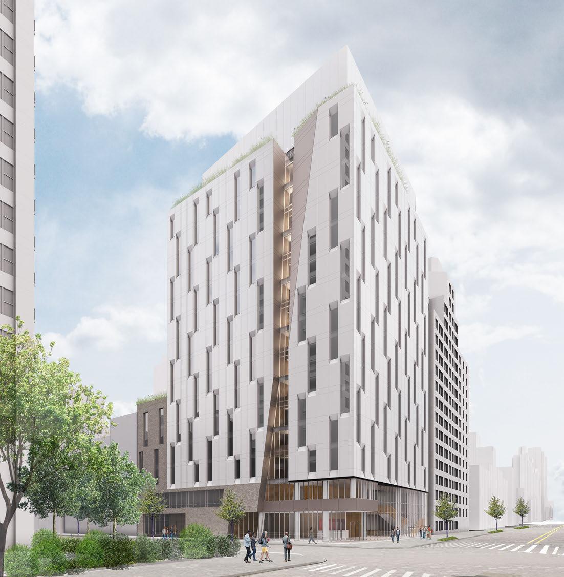
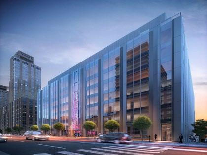
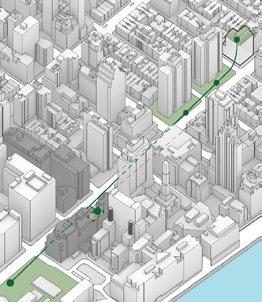
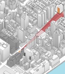
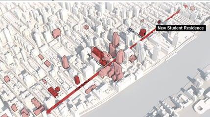
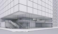
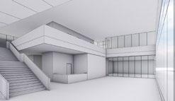
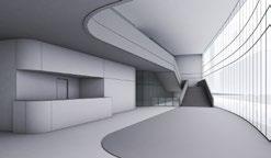
Facade design is a fundamental component for this new construction higher education dormitory. The primary driver is the sight lines and green spaces from the neighboring campus buildings to establish the buildings exterior form. Maximizing the unit mix efficiency for space and cost is imperative. Additionally designing a vibrant student commons area that reflects the culture of the school was the second significant element.
Size: 167,000 SQ FT
Cost Estimate: Unknown
Phase: Pre-SD and SD
My Role: Lobby planning, amenity planning, student common planning, core planning, unit mix layout, unit design
18
The Connected Experience
The Connected Experience
The Connected Experience
The Connected Experience
Campus Map
Campus Visual Connection
The Connected Experience
Access and Connection
Access and Connection
Access and Connection
Access and Connection
Urban Response
Urban Response
Urban Response
Contextual Response via Form
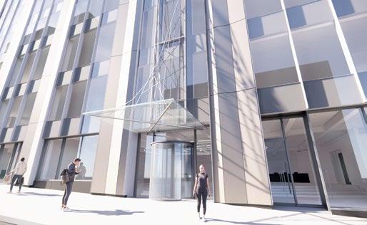
At the base, the glass lobby wall peels away from the street to orient the main entry toward the campus core and invite access to the building.
At the base, the glass lobby wall peels away from the street to orient the main entry toward the campus core and invite access to the building.
At the base, the glass lobby wall peels away from the street to orient the main entry toward the campus core and invite access to the building.
At the base, the glass lobby wall peels away from the street to orient the main entry toward the campus core and invite access to the building.
The visual connection to and from campus is formally expressed on level 2 and carries up through each floor of the building.
The visual connection to and from campus is formally expressed on level 2 and carries up through each floor of the building.
Campus Green Space Connection
Texture and Fenestration
Texture and Fenestration
Texture and Fenestration
Texture and Fenestration
Urban Response
The building provides a relief from the surrounding residential context with a material change at the base and west combined with a formal relief at the north.
The building provides a relief from the surrounding residential context with a material change at the base and west combined with a formal relief at the north.
The building provides a relief from the surrounding residential context with a material change at the base and west combined with a formal relief at the north.
The building provides a relief from the surrounding residential context with a material change at the base and west combined with a formal relief at the north.
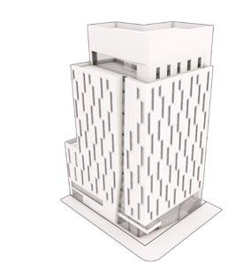
The visual connection to and from campus is formally expressed on level 2 and carries up through each floor of the building.
The visual connection to and from campus is formally expressed on level 2 and carries up through each floor of the building.
This articulation reflects the program shift at levels 1 and 2 and identifies the building as functionally different from the surrounding residential buildings.
This articulation reflects the program shift at levels 1 and 2 and identifies the building as functionally different from the surrounding residential buildings.
This articulation reflects the program shift at levels 1 and 2 and identifies the building as functionally different from the surrounding residential buildings.
This articulation reflects the program shift at levels 1 and 2 and identifies the building as functionally different from the surrounding residential buildings.
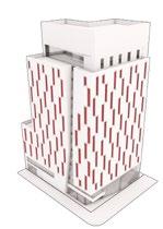
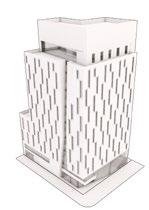




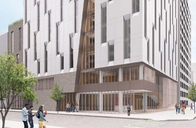
Residential windows are grouped across two floors and staggered to emphasize the verticality and diagonal movement characteristic of the campus architecture. The repetitive pattern provides a contrast to the moment of carving and can take multiple forms in future studies.
Residential windows are grouped staggered to emphasize the verticality movement characteristic of the The repetitive pattern provides moment of carving and can take studies.
Residential windows are grouped across two floors staggered to emphasize the verticality and diagonal movement characteristic of the campus architecture. The repetitive pattern provides a contrast to the moment of carving and can take multiple forms studies.
Residential windows staggered to emphasize movement characteristic The repetitive pattern moment of carving studies.
35
36
Residential Floor Planning Approach
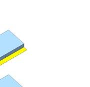
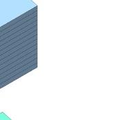
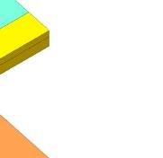
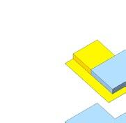
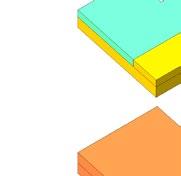
Bedroom Unit - Type 1
Type 1 Units located on Levels 3-6 in a vertical line
Unit can be planned as ADA compliant
Multiple options possible for kitchen configuartion
Furniture shown for scale and reference only. Specific furniture sizes and types to be developed at a later date.
allowable best their slightly configuration types
• Type 1 Units are planned to be located on Levels 3-16.
• Units are located intended to be stacked in a vertical line and paired with the Trash Room and an adjacent ADA Studio Unit.
• Unit can be planned as ADA compliant
• Limited options available for kitchen configuration
• Furniture shown for scale and reference only. Specific furniture sizes and types to be developed at a later date.

or Accessible Type Unit)
20 74th St New Student Residence
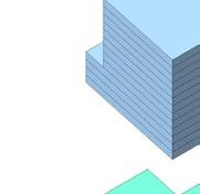
Levels 3-6 18 Studio Units 2 Two Bedroom Unit 10 Studio Units 4 Two Bedroom Unit 14 3 Levels 7-13 Approx. 74% eff. 74th St New Student Residence Residential Floor Planning Approach Levels 14-15 Level 16 4 Studio Units 1 Two Bedroom Unit 4 Studio Units 4 One Bedroom Unit 3 Two Bedroom Unit Approx. 71% eff. L 16 Student Residences and Terrace L 03 - 15 Student Residences L 02 Student Life and Medical Student Admissions L 01 Student Commons and Building Operations C 01 - C 02 Fitness and Wellness YorkAve XXthSt 74th St New Student Residence | Overseers' Review #2 | 06.19.20 1 Bedroom Unit Type 1 2 Modules 585 SF (B+NYC
27’-3” 25’-1” 15’-11” 9’-2” 3’-4” MIN. CLEAR 12’-2” 10’-11”
9’-3” 9’-3” 25’-2” 9’-2” 15’-7” 27’-3” 3’-4” MIN. CLEAR 2 Bedroom Unit
1 2.25 Modules 656 SF (B+NYC or Accessible Type Unit)
Type
29’-9 1/2” 9’-8 1/2” Studio
Studio Unit Type 1 1 Module 299 SF (B+NYC Type Unit) 13’-0” 25’-9” 27’-3” 12’-9” 12’-4” 4’-3” 12’-10” 74th St New Student Residence | Overseers' Review #2 | 06.19.20 49 Residential Floor Planning Approach Levels 3-6 18 Studio Units 2 Two Bedroom Unit 10 Studio Units 4 Two Bedroom Unit 14 Studio Units (Level 07) 3 Two Bedroom Unit (Level 07) Levels 7-13 Approx. 74% eff. Approx. 71% eff. Studio Unit 1 Bedroom Unit 2 Bedroom Unit Diagramatic Program Stack C 01 - C 02 Fitness and Wellness L 01 Student Commons and Building Operations L 02 Student Life Student Admissions L 03-15 Student Residences L 16 Student Residences Terrace Student Residence Unit Mix L 03-06 18 Studios 2 Two Bedrooms L 07-13 10 Studios 4 Two Bedrooms L 14-15 4 Studios 4 One Bedrooms 3 Two Bedrooms
2 Bedroom Unit - Type 1

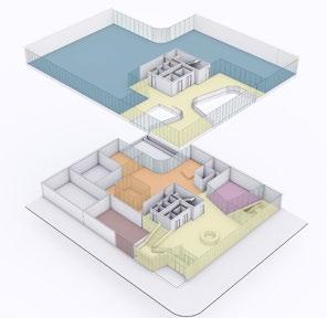
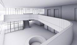
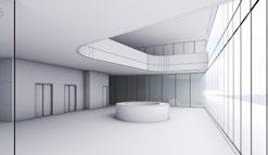
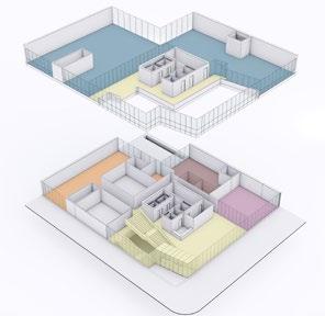


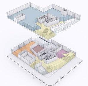
21 Lobby Student Commons MEP / BOH Stair Up to Admin Suites Stair Down to Cellar Levels Student Collaboration / Student Life 74th St New Student Residence | Overseers' Review #2 | 06.19.20 76 Lobby Level Approach 03 - Space & Experience 74th St New Student Residence | Overseers' Review #2 | 06.19.20 74 Lobby Level Approach 01 - Space & Experience 74th St New Student Residence Lobby Levels Planning Approach - Option Summary Student Commons Business Center Student Courtyard / Outdoor Activity Music Rooms Lobby Mail & Package Student Collaboration / Student Life Toilet Stair Up to Admin Suites Option 01 Option 02 74th St New Student Residence | Overseers' Review #2 | 06.19.20 75 Lobby Level Approach 02 - Space & Experience Option Summary Lobby Mail & Package Student Commons Business Center MEP / BOH TBD Trash / Recycling Toilet Toilet Student Courtyard / Outdoor Activity Music Rooms Stair Up to Admin Suites Stair Down to Cellar Levels Student Collaboration / Student Life Lobby Mail & Package Student Commons Business Center MEP / BOH TBD Student Collaboration / Student Life Trash / Recycling Toilet Toilet Student Courtyard / Outdoor Activity Music Rooms Stair Up to Admin Suites Stair Down to Cellar Levels Option 02 Option 03 Student Amenities Opt 1 Student Amenities Opt 2 Student Amenities Opt 3
IV
11 Penn Plaza


36
11 Pennsylvania Plaza
11 Pennsylvania Plaza, New York, NY 10001
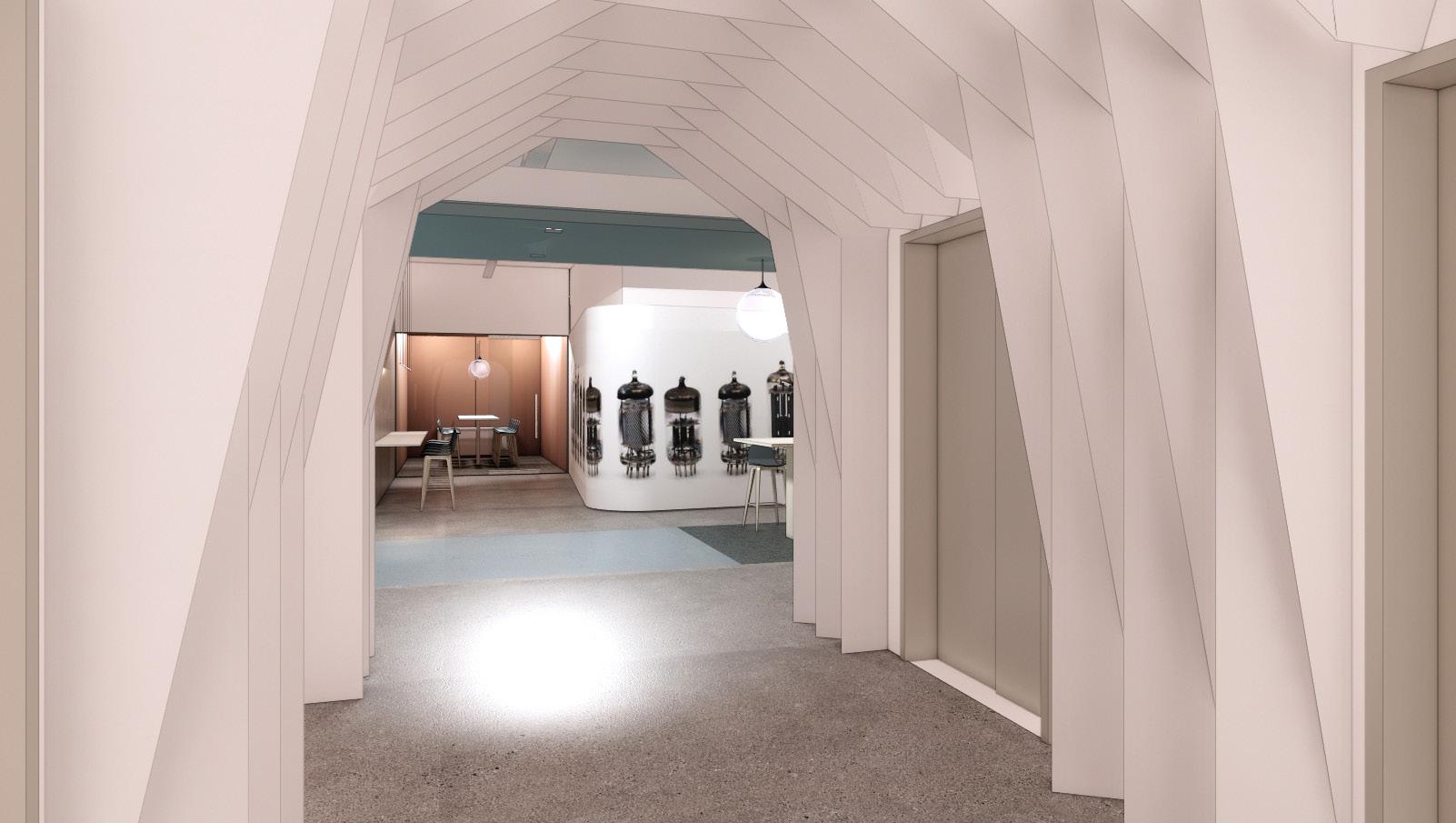
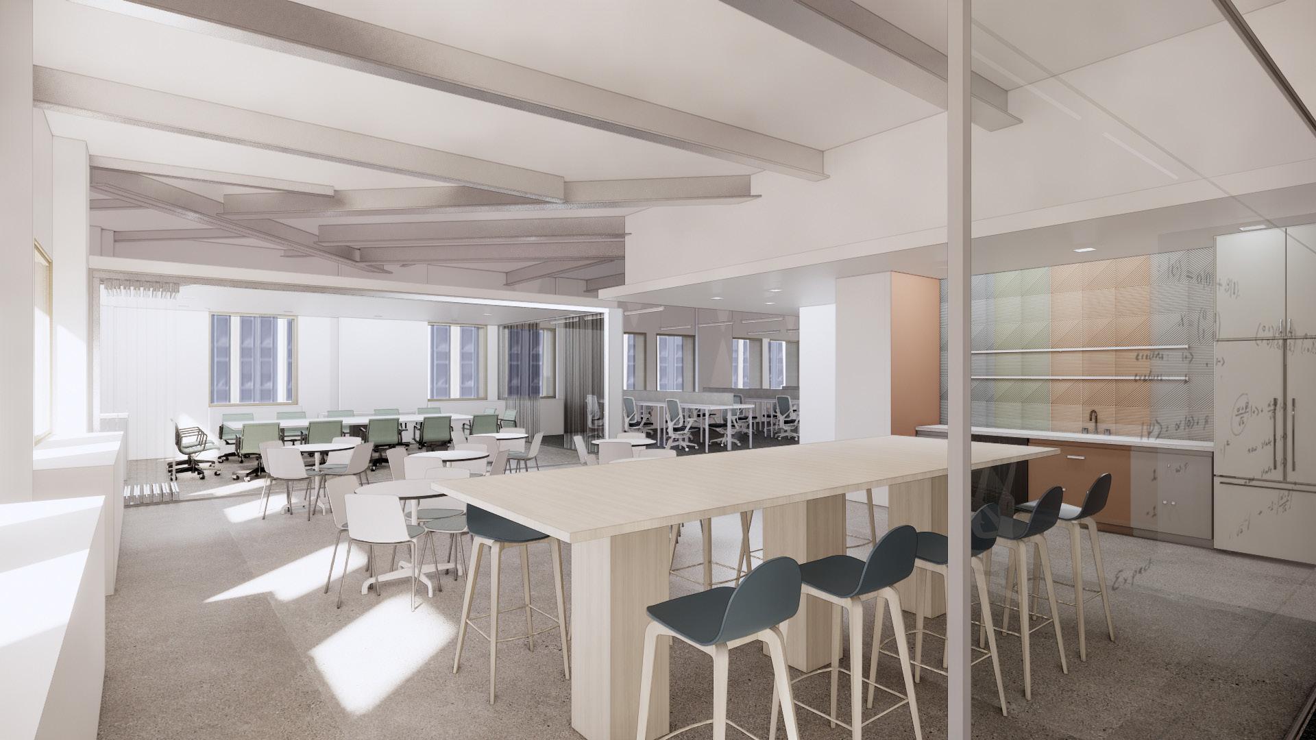
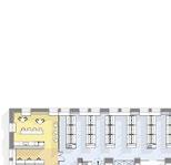
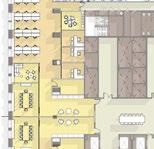
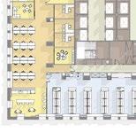
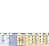
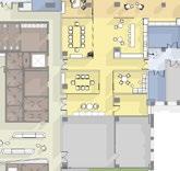
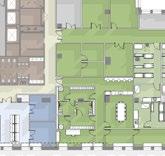
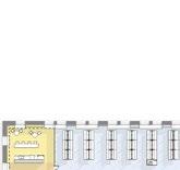
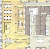
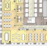
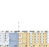
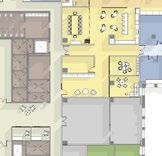
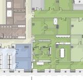
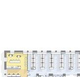
The history of the building and its proximity in manhattan is the inspiration for this current office space set to be re envisioned as science and technology laboratory/ office fitout. 11 Penn Plaza is directly across from New York Pennsylvania Station and has preserved its defining art deco characteristics. The area is a hub for inter-state travel as well as within manhattan on MTA’s subways system. To celebrate the history of this location the design of this space is centered around the use of designated ‘hubs’ to creative a unique layout. The design references historically significant technology and transportation elements from the Penn Plaza area while adding a modern feel by using colors extrapolated from key components of non production laboratory hardware to brighten a space that is traditionally sterile and white. This lab will act as a way of establishing this area as a new age of innovation just as it did in the early 1900’s.
Size: 1,100,000 SQ FT
Cost Estimate: Unknown
Phase: SD, unbuilt
My Role: Alteration-I permiting, test fits, interior finish palette, code compliance, renderings, elevator lobby portal, MEP consultant coordination
24
new Vornado Labs at a major amenities.
top talent with a high quality connectivity and will pulsate new age of innovation.
Finally, the Labs will carry the potential
Transportation Hub Diagram
New York City MTA Map, Mishka Prints
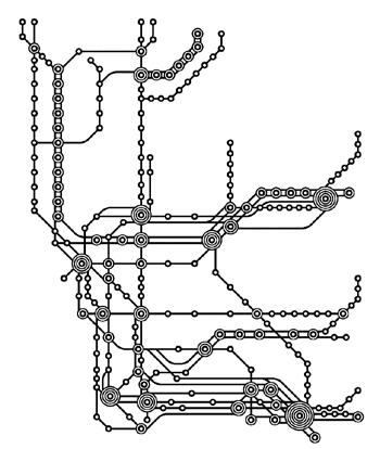
MTA Map, Mishka Print
Elevator Lobby Offices and Meeting Rooms Niche Spaces Floating Meeting Rooms
Reception / Check-in Pantry and Conference Room Open Office Lab Support
Programatic Hub Abstraction
25 New Jersey Philadelphia DC Boston Connecticut Bronx New York State Brooklyn Long Island
Tenant Tenant Tenant Tenant 2 3 1 3 5
1/32”
11 Penn Plaza - Design Review Parti Diagram
= 1’-0”
Lab Equipment Core Envelope
Tenant Separation
Lab
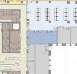
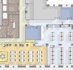
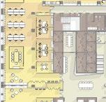
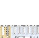
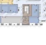
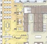
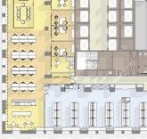
3 Tenant + Vivarium Test Fit
LEVEL 04 -TEST-FIT




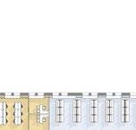
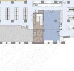
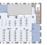

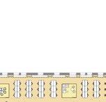








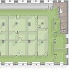

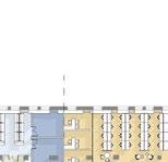
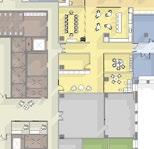
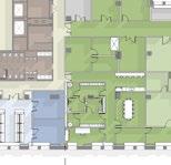











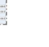


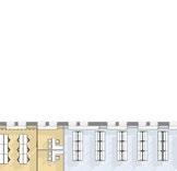
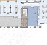
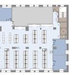

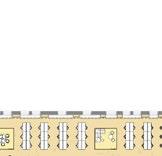
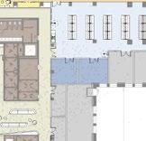
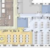

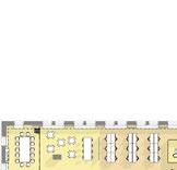






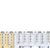


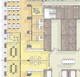
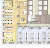


2 Tenant Test Fit


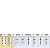
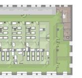
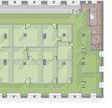
WORK SPACE COUNT WORKSTATIONS WORK SPACE COUNT WORK SPACE COUNT Scale: 1/32" = 1'-0" LEVEL 04 -TEST-FIT LAB SUPPORT LAB SUPPORT TENANT IDF WORK SPACE COUNT PRIVATE OFFICES CONFERENCE ROOMS 2 LAB SUPPORT ROOMS WORK SPACE COUNT PRIVATE OFFICES CONFERENCE ROOMS LAB SUPPORT ROOMS LAB SUPPORT LAB SUPPORT OPEN OFFICE CHECK-IN AREA LEGEND AMENITY LAB SUPPORT OFFICE SHARED VIVARIUM VIVARIUM SUPPORT CHECK-IN LAB SUPPORT OPEN LAB LAB SUPPORT LAB SUPPORT COLD STORAGE JC CLEAN STORAGE VIVARIUM SERVICES TENANT 2 TENANT 1 EQUIPMENT EQUIPMENT WORK SPACE COUNT PRIVATE OFFICES CONFERENCE ROOMS WORKSTATIONS 24 @ 5' LAB BENCHES FUME HOODS LAB SUPPORT ROOMS WORK SPACE COUNT PRIVATE OFFICES CONFERENCE ROOMS WORKSTATIONS LAB BENCHES FUME HOODS LAB SUPPORT ROOMS WORK SPACE COUNT PRIVATE OFFICES 3 CONFERENCE ROOMS LAB SUPPORT ROOMS 6 (28 DOUBLE RACKS PROCEDURE ROOMS 7 (INCLUDES NECROPSY Scale: 1/32" = 1'-0" LEVEL 04 -3 TENANTS & VIVARIUM CHECK-IN AREA LEGEND AMENITY CORE LAB LAB SUPPORT MEP OFFICE SHARED VIVARIUM VIVARIUM SUPPORT OPEN LAB LAB SUPPORT STORAGE STORAGE STORAGE PH.PH. LAB SUPPORT PPE OPEN LAB OFFICE OFFICE HUDDLE CONFERENCE HUDDLE CLOSET OFFICE PANTRY OPEN OFFICE MEP MEP LAB SUPPORT LAB SUPPORT LAB SUPPORT LAB SUPPORT LAB SUPPORTLAB SUPPORT OFFICE OFFICE HUDDLE CLOSET OFFICE OPEN OFFICE RECEPTION PROCEDUREPROCEDUREPROCEDUREPROCEDUREPROCEDURE HOLDING HOLDING HOLDING HOLDING HOLDING HOLDING JC CLEAN STORAGE VIVARIUM SERVICES GOWNING LOCKER SH. WC LOCKER WC SH. VET OFFICE TRAINING DEBOXING/ CAGE TRANSFER QUARANTINE CLEAN CAGES COLD STORAGE DIRTY CAGES/ STORAGE MEP TRASH LAB SUPPORT LAB SUPPORT OFFICE OFFICE OFFICE CONFERENCE HUDDLE RECEPTION CONFERENCE MEP EQUIPMENT EQUIPMENT PANTRY TENANT 2 TENANT 1 TENANT 2 TENANT 3 TENANT 3 VIVARIUM CLOSET EQUIPMENT EQUIPMENT PPE PPE HUDDLE COPY/PRINT PANTRY OPEN OFFICE OPEN LAB BEHAVIORAL PROCEDURE NECROPSY TENANT 1 - WORK SPACE COUNT PRIVATE OFFICES 3 HUDDLE 2 CONFERENCE ROOMS 1 WORKSTATIONS 48 @ 5' LAB BENCHES 68 @ 5' FUME HOODS 3 @ 5' LAB SUPPORT ROOMS 6 TENANT 2 - WORK SPACE COUNT PRIVATE OFFICES 3 HUDDLE 2 CONFERENCE ROOMS 1 WORKSTATIONS 24 @ 5' LAB BENCHES 45 @ 5' FUME HOODS 2 @ 5' LAB SUPPORT ROOMS 2 TENANT 3 - WORK SPACE COUNT PRIVATE OFFICES 3 HUDDLE 2 CONFERENCE ROOMS 1 WORKSTATIONS 24 @ 5' 64' Scale: 1/32" = 1'-0"
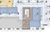
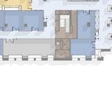
AREA LEGEND AMENITY CORE LAB LAB SUPPORT MEP OFFICE SHARED MEP TENANT 1 MEP LAB SUPPORT OFFICE LAB SUPPORT OFFICE TENANT IDF ELEVATOR LOBBY TENANT 1 - WORK SPACE COUNT PRIVATE OFFICES 4 HUDDLE 6 CONFERENCE ROOMS 2 WORKSTATIONS 60 @ 5' LAB BENCHES 96 @ 5' FUME HOODS 3 @ 5' LAB SUPPORT ROOMS 5 TENANT 2 - WORK SPACE COUNT PRIVATE OFFICES 6 HUDDLE 5 CONFERENCE ROOMS 2 WORKSTATIONS 84 @ 5' LAB BENCHES 105 @ 5' FUME HOODS 3 @ 5' LAB SUPPORT ROOMS 4 COPY/PRINT HUDDLE CLOSET TENANT 2 MEP MEP LAB SUPPORT LAB SUPPORT LAB SUPPORT LAB SUPPORT WASTE CYL TBD LAB SUPPORT LAB SUPPORT LAB SUPPORT PANTRY CHECK -IN OPEN OFFICE CONFERENCE HUDDLE OPEN OFFICE HUDDLE HUDDLE PANTRY OPEN LAB PPE PPE HUDDLE OPEN LAB HUDDLE HUDDLE COPY/PRINT HUDDLE HUDDLE CLOSET OPEN OFFICE CONFERENCE EQUIPMENT EQUIPMENT EQUIPMENT EQUIPMENT SHELVES CHECK-IN OPEN OFFICE CONFERENCE EQUIPMENT EQUIPMENT MOTHERS ROOM CLOSET CLOSET OFFICE OFFICE OFFICE OFFICE CLOSET HUDDLE OFFICE OFFICE OFFICE HUDDLE OFFICE CLOSET CONFERENCE 0 16'32' 64' LEVEL 06 -2 TENANTS
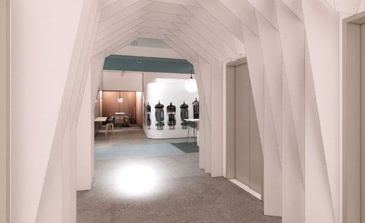

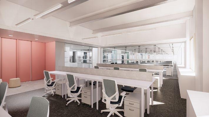
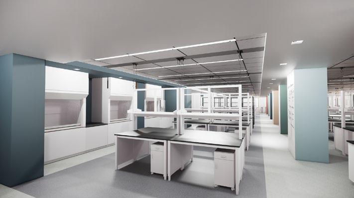
27 29 11 Penn Plaza - Design Faraday Cube - Looking East Into Lab 33 Lab Entry - Looking East 35 11 Penn Plaza - Design Review
Open Office Hub
Floating Meeting Hub
Elevator Lobby Hub
Undisclosed Children’s Hospital
V

Undisclosed Children’s Hospital Clinical Fit-Out
East Coast, USA
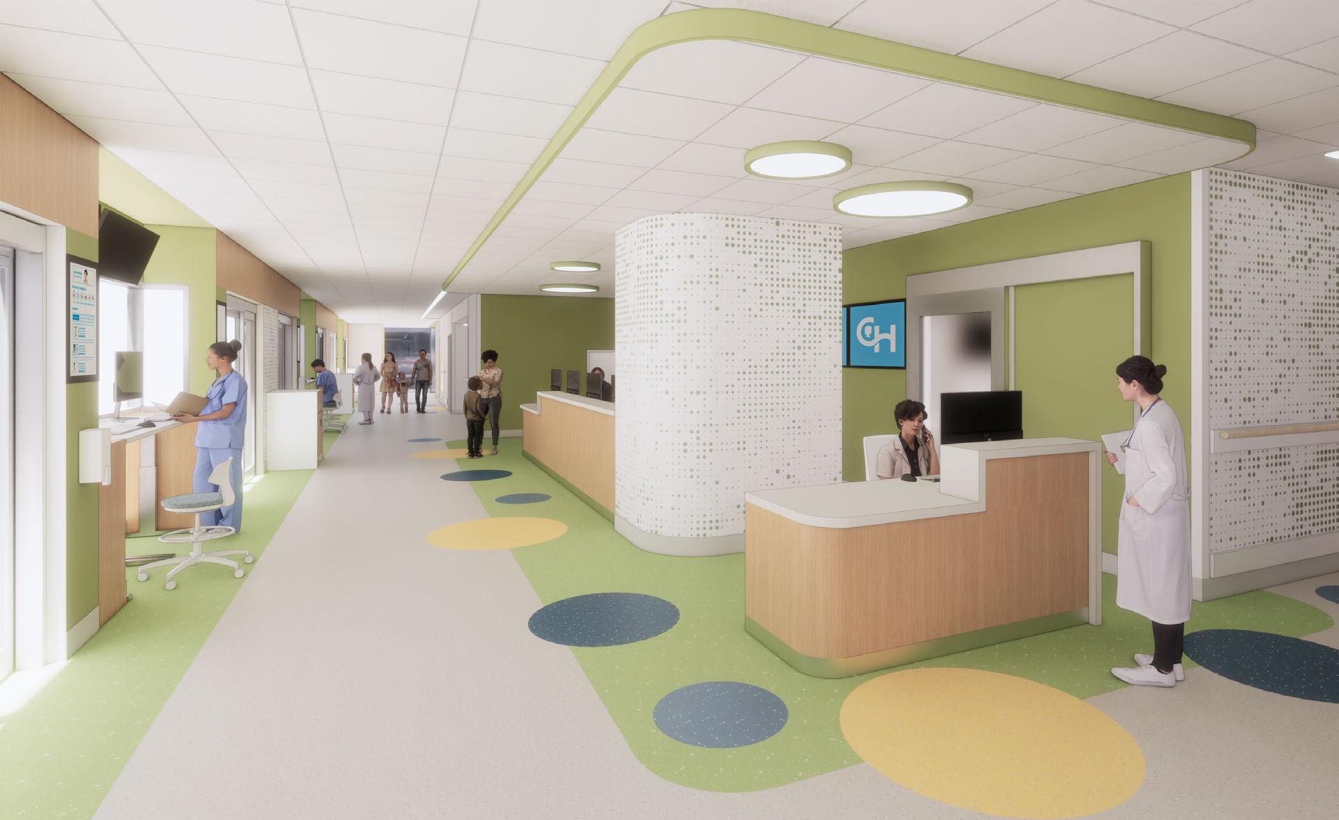
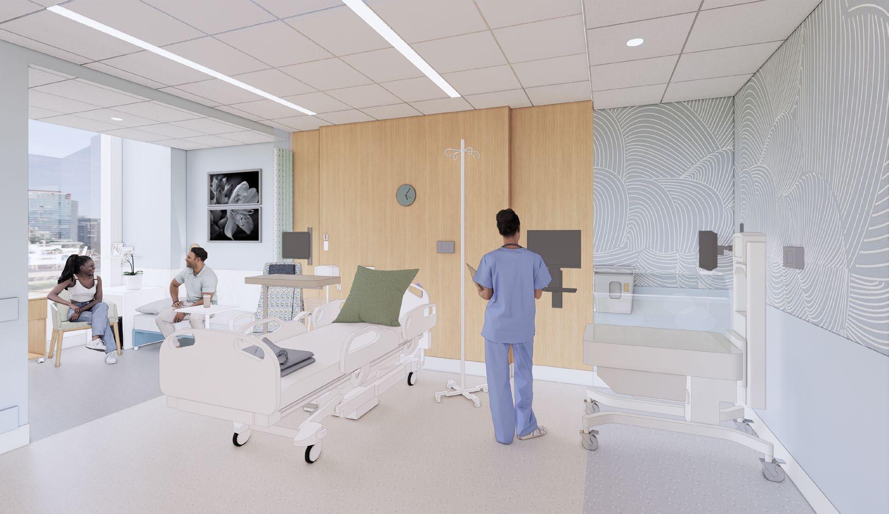
This massive 26 story Healthcare project incorporates a cutting edge ICU bed tower, multiple MRI’s, specialty OR’s, an outpatient fetal heart disease specialist and a Special Delivery Unit. Creating a welcoming and friendly environment for both children and their families is crucial while experiencing potentially tough times. Through the use of light tones and soft textures the spaces remains calming. The design also brings in pops of bright color and interactive opportunities called “Discovery Moments,” some of which are visual and others which are through touch. While patients are always the number one priority in healthcare, it is equally as important to design ergonomic and flexable spaces for the staff to do their life saving work. Dedicated staff spaces are thoughtfully designed to be a sanctuary of relief from the stress they experience all too often.
Size: 1,200,000 SQ FT
Cost Estimate: Approx. $ 2,200,000,000
Phase: DD through CD(present)
My Role: Clinical user group design meetings, Owner Rep. presentations, Code compliance, MEPFP coordination, Lighting coordination, Test Fitting, BIM management, Mock-up, OR Surgery Simulations
30
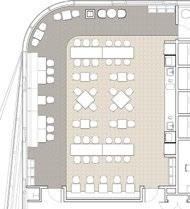
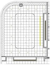
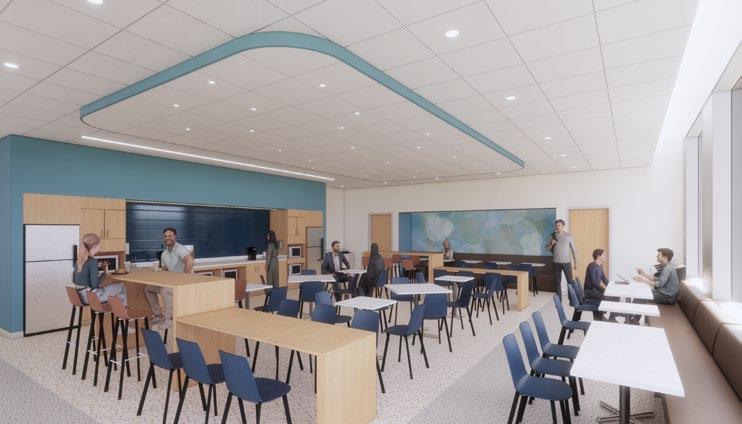


31 CHOP NEW PATIENT TOWER | 6TH FLOOR STAFF SPACES STAFF LOUNGE RENDERED FLOOR PLAN + RCP ENLARGED INTERIOR DESIGN SIGN-ON PACKAGE ALIGN ALIGN ALIGN ALIGN ALIGN ALIGN ALIGN ALIGN ALIGN ALIGN ALIGN ALIGN ALIGN ALIGN 1 3 K.3 K J.3 J H.9 H.3 H G J.9 1.9 H.1 2 2.7 06243 06250 CORRIDOR--35' 0" 35' 0" 35' 0"006240 CORRIDOR 06243 ESD (D) 14A 14A 14A 14A 14A 14A 14A 3AP H.26 G.3 A806.56 20 14A 14A 5BP 4BP 5B2 4B 17BP 5BP 5B 5B 5B 5BP 5B 17B 5B 5B 5B 4BP 17B 17B 17B 17B 17B 17B 17B1 54B1 5BP 3A 14AP 17B 4B 4B 5B 17B 5B 17B 4BP 21 3A 17B 3A 17B 3A 3A 14A 3A 3A 14A 3A 3A 17B 3A 4BP 3A 17B 14B 4B 14B 4B 14B 4B 14B 14B 3A 3A 3A 17BP 4BP 17BP 17BP 4BP 17BP 17BP 17BP 4BP 4BP 4BP 14B 14 14B 14B 4BP 17BP 3A 5B 17B 5B 4B 3A 5B 17B 17B 4B 4BP 17BP 3B1 17B 5B 3A 5B 5B 4B 4B 4B 4B 4B 4B 4B 5B1 5B1 5B1--4 C RC R-CLEAR 8' 0" 1' 6"1' 7"HOLD 4' 0"1' 4" 1/4" 10' 3/4" 7' 4" P---C REQEQ 1' 1"5' 1/2" 17' 4" 5' 0"C R511' 0"1' 0"3O351/2" 2' 11 1/2" 1' 6" 5' 10 1/2" HOLD 5' 1" O L16"66 16 1' 6" A806.52 14 A806.52 14 A806.56 10 11 A806.52 16 06215 LOCKER VESTIULE A806.57 MENS LOCKER 06214B MENS SCRUBEX MENS TOILET 06214A MENS SCRUBEX MENS SHOWER 06216 WOMENS LOCKER 06221 STAFF LOUNGE 06222E PHONE ROOM 06222D PHONE ROOM 06222A HUDDLE 06222F HUDDLE 06222G PHONE ROOM OFFICE 06222J OFFICE 06222K OFFICE OFFICE OFFICE VALVE GALLERY 06232 BUSINESS CENTER 06241 ADMINISTRATION 06241C OFFICE OFFICE 06241A OFFICE ON CALL ADA ROOM 06242B ON CALL ADA TLT OFFICE 06241E OFFICE 06241D OFFICE 06242F ON CALL ROOM 06242E ON CALL ROOM ON CALL ROOM ON CALL ROOM A806.57 A806.57 A806.57 8 A806.57 A806.57 11 A806.57 A806.56 16 18 17 A806.56 15 A806.56 14 14 06213 06214A 06244 06214B 06221.2 06221.1 06231 06241 06242A 06242C 06242D 06242E 06242F 06241G 06241G CLOSET 06232.3 3B1 24B1 17BP EQEQ EQEQ 06230B 06230A 1' 4"1' 4" ELEC. 06230B ELEC. CORRIDOR 06252 ON CALL VESTIBULE 3AP 3AP 06251 STORAGE EQ EQ 06251 A800.64 2 A800.64 366 1' 6"61' 6" 1' 6"6 1' 6" 1' 6" 1' 6"O L114AP 19 3A 5B1 06260 CORRIDOR4 4B 4B 06222C PHONE ROOM 06222B PHONE ROOM 06320 6" 3AO-1 OFEC-1 06230 CORRIDOR 06230 DM-05 DM-05 HOLD 1' 6" 6" 1' 6" 1' 6"H DO L-82-22 8-21 O-14A 14A 14A 5BP 4B FEC-1 FEC-1 17BP LINE OF SOFFIT ABOVE LINE OF SOFFIT ABOVE 06222G 06222H 06222J 4B 06222K DM-05 06232M 06222L CLEAR C N N U R N C N N U R N DM-05 06222E 06222D 06222B C T N S R O O U 06241C DM-05 06241B 06241A 9" F O O U 06241D CLEAR 06232.1 1 HOUR 2 HOUR 3 HOUR F L O O R P L A N L E G E N D SMOKE PARTITION ("P" DESIGNATION IN AREA PLANS) MILLWORK STAINLESS STEEL HATCHED, REFER TO THE PUBLIC SPACE AREA PLANS WITH A WELL AS CORE SHELL DRAWINGS FOR FURTHER 1. REFER TO CONTROL PLANS FOR SLAB EDGES, DEPRESSIONS AND OPENING LOCATIONS. REFER TO PARTITION TYPE SCHEDULE ON SHEETS 601.1 AND 601.2. 3. REFER TO A610 SERIES SHEETS FOR DOOR SCHEDULE, FINISH LEGEND, AND WALL 4. REFER TO A630 SERIES SHEETS FOR FINISH SCHEDULE 6. PROVIDE CONCEALED BLKG. WITHIN PARTITIONS -MOUNTED ITEMS, INCLUDING TOILET ACCESSORIES AND EQUIPMENT PROVIDED BY OWNER. REFER TO ALL DISCIPLINE'S DRAWINGS FOR EQUIPMENT, WALL MOUNTED. 7. REFER TO INTERIOR ELEVATIONS AND ENLARGED PLANS FOR ADDITIONAL TAGS NOT SHOWN IN 8. GLASS GUARDRAILS TO TERMINATE 1/4" FROM FACE OF INTERSECTING PARTITION, TYP. 9. REFER TO A634 FOR TYPICAL ROOM AND SCHEDULE. 10. REFER TO A635 FOR KEYNOTE LEGEND AND SUPPORTING 3D RENDERING VIEWS FOR PUBLIC RENDERINGS. 11. ALL SILL PARTITION TYPES ARE 14B, WALL STOPS AT SILL, SEE DETAILS. F L O O R P L A N G E N E R A L N O T E S ENLARGED PLAN 1/4" = 1'-0" 1 6TH FLOOR PLAN AREA P08 MATCHLINE MATCHLINE MATCHLINE A206.07 A206.01 MATCHLINE A206.01 Staff Lounge RCP Staff Admin (Lounge, Business Center, Office, On-Call, Locker Room) Staff Lounge Sanctuary INTERIOR DESIGN SIGN-ON PACKAGE AUGUST 11, 2023 CHOP NEW PATIENT TOWER | 6TH FLOOR STAFF SPACES STAFF LOUNGE RENDERED FLOOR PLAN + RCP FLOOR PLAN ENLARGED RCP 10’-0” AFF 9’-8” AFF 7’-6” AFF Staff Lounge Rendered Finish
CHOP NEW PATIENT TOWER | INPATIENT UNIT CARE TEAM STATION PERSPECTIVE - ENVIRONCARE


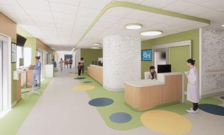
32 ALIGN ALIGN ALIGN ALIGN ALIGN ALIGN ALIGN TF 5 5.3 6 6.3 K.3 K J.3 J H.9 H.3 H G J.9 6.1 6.4 H.1 A800.63 A809.10 14 LDRP LDRP LDRP SOILED WORKROOM ANESTH. CLEAN WORK. ESD (D) A.P./P.P. NOURISHMENT ELEC. INFANT STABILIZATION AND RESUSCITATION 09181A ALCOVE 09150B ALC, CODE CART 09141 STAFF TLT. PUBLIC TLT. ELEC. EQUIP. STOR. 09312 ESD (D) 09169 MEDS 09168 CLEAN SUPPLY CORRIDOR 09168 09361 09166 09170B 09170A 09150D 09169 A809.11 A809.10 1 A820.5 ALC., PPE PAT TLT 09005B 09006B 09009.3 09009B PAT TLT 09010.2 09010B 09010B PAT TLT FEC 14A 8B 19B 8B 17B 14A 8BP 13B 13B 14A 13B 5BP 8B A809.05 1 MECH SHAFT 2 MECHANICAL CLOSET PLINTH MECHANICAL EMERG POWER TDR-LV TDR-IS G.3 5B1 5B1 14B 14A 3A1 8B1 8B1 14A 14A 14A 8BP 19B 8B 8B 5B 19B 19B 17B 17B A809.13 2 A809.06 9 09323 C-SECTION - SDU OR (AW) 09322 INFANT RESUSCITATION 09310B ALC., EQUIP 09310D SCRUB 09310C ALC., EQUIP 09323.1 09322.2 09322.3 09324.2 09324 INFANT RESUSCITATION 8B 17A 19B 8B 17A 8B 8B1 8B1 8B 17A 17A 8B 19A 8B 19B 8B 8B 17B 19B 19B 10 A800.54 11 09414 09313 09312 09310.1 8B1 5B1 5BP 09008A PPE 09009A PPE CORRIDOR 09320A 09182 CARE TEAM CORRIDOR 09310 SEMI-RESTRICTED CORRIDOR 09361 SOILED HOLDING 09310E ALC., STRETCHER 14B 14B FEC-1 FEC-1 - TUBE P - TUBE 8B 17B 4' EQEQ EQ EQ HOLD 1' 6" 9" EQ EQ EQEQ 2' 6" HOLD 0" 4' 0" HOLD 2' 6" HOLD 2' 6" 12' 11" 4' 11" EQEQ EQEQ EQ EQ EQ EQ 2" 0" 3' 2" HOLD O2 10 2A 2Q E6 1' 6 3/4" 7' 10"6" 3' 0 1/2" CLEAR 5' 2"1' 6"1' 5"2' 7"4' 8" 9' 8 1/2" 19B1 3B1 1/2"2' 1/4"12-1' 9"5' 0" 5' 0"68' 0" 2' 3" 15' 6 1/2"---614A2' 1/2"1' 9"E A1-E6 10"1/2" 2' 1/2" 8"3' 0 1/8" 6' 8"1 6-2 TYP. 1' 5" 11 0 7' 1/2"614A 8B10--CLEAR 8' 0" 8BFEC-1 HOUR HOUR F L O O R P L L E G E N D SMOKE DESIGNATION PLANS) HOUR HOUR STAINLESS COUNTERTOP HATCHED, THE PUBLIC AREA PLANS WELL AS DRAWINGS INFORMATION. 1. REFER TO CONTROL PLANS FOR DEPRESSIONS AND OPENING LOCATIONS. 2. REFER TO PARTITION TYPE SCHEDULE 3. REFER TO A610 SERIES SHEETS SCHEDULE, FINISH LEGEND, AND 4. REFER TO A630 SERIES SHEETS SCHEDULE 6. PROVIDE CONCEALED BLKG. WITHIN -MOUNTED ITEMS, TOILET ACCESSORIES AND EQUIPMENT PROVIDED BY OWNER. REFER DISCIPLINE'S DRAWINGS FOR WALL MOUNTED. 7. REFER TO INTERIOR ELEVATIONS A100 PLANS. 8. GLASS GUARDRAILS TO TERMINATE FACE OF INTERSECTING PARTITION, LACTATION ROOM PLAN AND ACCESSORY SCHEDULE. 10. REFER TO A635 FOR KEYNOTE AREAS. REFER TO A890 SHEETS RENDERINGS. ALL SILL PARTITION TYPES ARE AT SILL, SEE DETAILS. F L O O R P L G E N E R A L N O AFF. ENLARGED PLAN MATCHLINE A209.4 A209.1 MATCHLINE A209.1 A209.2 MATCHLINE MATCHLINE A209.4 MATCHLINE A209.4 INTERIOR DESIGN
5/8" GYP. INSULATION 3 5/8" STUDS EXTERIOR WALL SYSTEM ALUMINUM CLOSURE, PAINT TO MATCH EXT. MULLION 5/8" GYP. 2 1/2" STUD @ 16" O.C. WALL BASE AS SCHEDULED ANCHOR BOLT EXTERIOR WALL SYSTEM, REFER TO EXT. DETAILS FOR MORE INFORMATION MULLION 2 1/4" EXTERIOR INSULATION EXTERIOR CONCRETE SLAB FIRE STOP FIRE STOP Z-CLIP ALIGN 5/8" GYP TO ALUMINUM CLOSURE. MULLION FIRE RESISTANT GASKET BLOCKING HSS STEEL FRAMING, SEE STRUC. DRAWINGS COLD-FORMED MTL. FRAMING DOUBLE LAYER 5/8" GYP MULLION GLAZING AS SCHEDULED BOLT CONNECTION 7'- 6" A.F.F. 3'- 6" A.F.F. 5/8" GYP CASEWORK TO RECEIVE POWER AND DATA FOR CARD READER ON BOTH DOORS IN CORR. AND ROOM DOUBLE LAYER 5/8" GYP. BEYOND CAULKING GASKET TO MAINTAIN SMOKE BARRIER TWO-WAY SLIDING TRACK MEDS BASKET PORCH PATIENT ROOM SOLID SURFACE COUNTERTOP INTERIOR STEEL COLUMN, SEE STRUCTURAL DRAWINGS FIRE PROOFING (2) 5/8" GYP. 2 1/2" STUD INSULATION 5/8" GYP. SHIM MINERAL WOOL EXTRUDED ALUMINUM W SCHEDULED PARTITION TYPE V FSLIDING TRACK EXTRUSION BLOCKING 3 5/8" BRACING STUD 3 5/8" STUD TO DECK DOOR AS SCHEDULED SMOKE SEAL EXTRUDED ALUMINUM CLOSURE CEILING AS SCHEDULED SCREWS 8" STUD TO B.O. DECK UNOCCUPIED CORRIDOR BRB CRB ARC BCC CSH D R A W N G SEAL: PROJECT TEAM: CONDITION OF USE WHEN THIS DOCUMENT IS SUPPLIED TO DOCUMENT IS SUBJECT TO THE CONDITIONS BALLINGER COPYRIGHT AND OTHER SUCH DOCUMENT. CONTRACTOR MAY MAKE ELECTRONIC THIS DOCUMENT AVAILABLE TO SUBCONTRACTORS, TO THIS STATEMENT OF CONDITIONS OF DOCUMENT BY BALLINGER SHALL NOT MAKE SUBCONTRACTOR'S SHOP DRAWINGS, NOR PREPARATION OF THEIR REQUIRED SHOP 39 WEST 19TH STREET, 12TH NEW YORK, NY 10011 T 212 624 4754 5802 RESEARCH PARK MADISON, WI 53719 T 608 238 2616 PHILADELPHIA, PA 19103 F 267 238 4001 THORNTONTOMASETTI.COM CHILDREN'S HOSPITAL OF PHILADELPHIA PHILADELPHIA CAMPUS NEW PATIENT TOWER SECTION DETAIL 1/2" = 1'-0" 4 TYP. INPATIENT FLOOR -KNEE WALL SECTION DETAIL SECTION DETAIL 1 1/2" = 1'-0" 8 OVERLOOK SLIDING DOOR SECTION DETAIL AXONOMETRIC 1 TYP. PATIENT ROOM -PASS THROUGH FRAMING AXONOMETRIC WALL TYPE 5B TO SUPPORT WINDOWS, PROVIDE HSS TUBE STEEL OR CFMF BOX BEAM. SECURE TO STRUCTURAL SLAB ABOVE. SUBMIT SHOP DRAWINGS PRIOR TO INSTALLATION FOR REVIEW GLAZING WITH INTEGRATED LOUVERS, ADD ALT. SMART GLASS MEDS PASS-THROUGH CABINET WALL TYPE 8B PATIENT FOOTWALL WALL TYPE 5B SWITCH FOR TASK LIGHTING WALL MOUNTED THERMOMETER Special Delivery Unit Axon of Staff Care Portal into Patient Room Care Team Station & Staff Care Portal
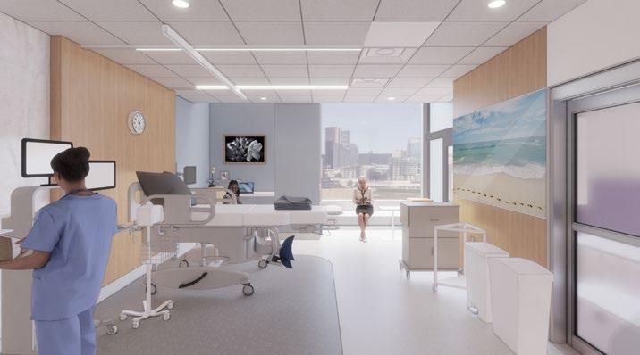
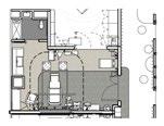
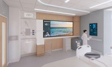

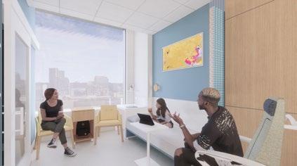
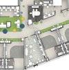
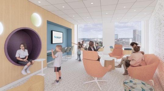

33 INTERIOR DESIGN SIGN-ON PACKAGE INTERIOR DESIGN SIGN-ON PACKAGE | AUGUST 11, 2023 CHOP NEW PATIENT TOWER | 9TH FLOOR SDU AP/PP ROOM PERSPECTIVE INTERIOR CHOP NEW PATIENT TOWER | INPATIENT UNIT INPATIENT ROOM PERSPECTIVE INTERIOR DESIGN SIGN-ON PACKAGE | AUGUST 11, 2023 CHOP NEW PATIENT TOWER | INPATIENT UNIT FAMILY LOUNGE PERSPECTIVE INTERIOR DESIGN SIGN-ON PACKAGE AUGUST 11, 2023 CHOP NEW PATIENT TOWER | INPATIENT UNIT INPATIENT UNIT RENDERED FLOOR PLAN Patient Room Footwall Family Zone in Patient Room Patient Room Perspective ICU Bed Floor “Discovery Moments” in Family Arrival


