B I M P O R T F O L I O
By Amar Kamble


NOTE: All drawings in the portfolio are not to the scale.
RIBA PROJECT STAGES & KEY LEARNINGS AND PROJECT OVERVIEW
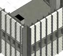
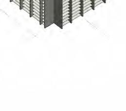
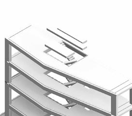
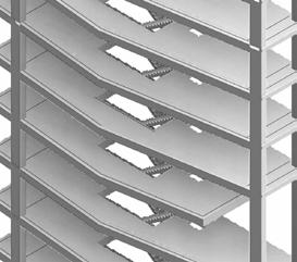
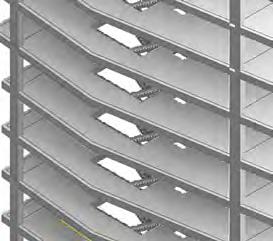
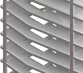
CONCEPT DEVELOPMENT & MASSING
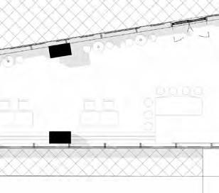
SITE PLAN
FLOOR PLANS
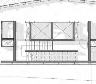
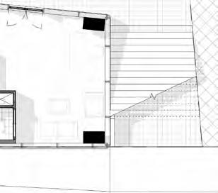
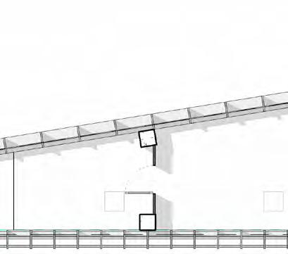
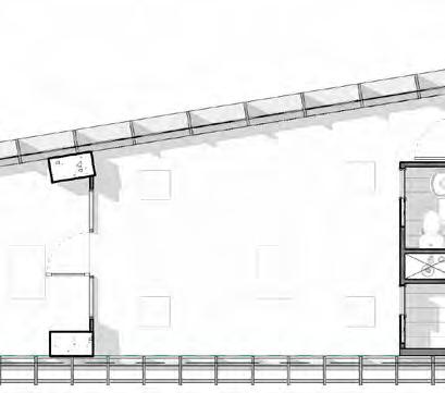
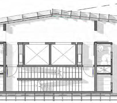
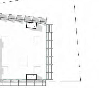
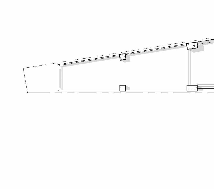
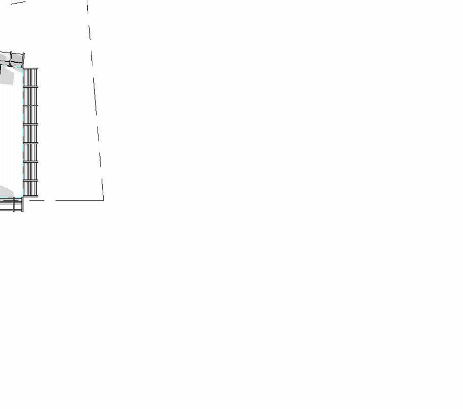
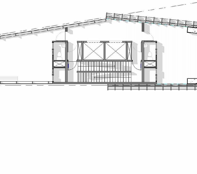
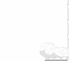
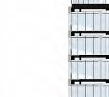
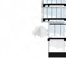
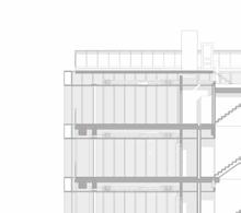
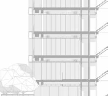
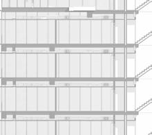
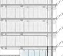
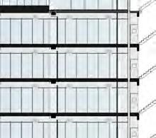
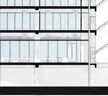
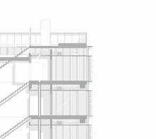
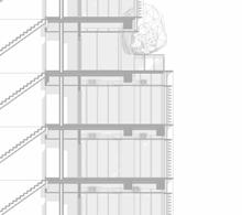
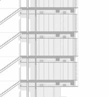
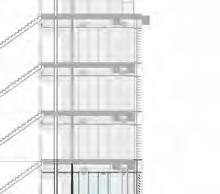
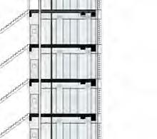
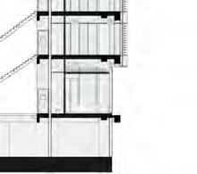
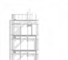
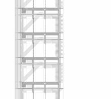
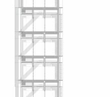
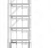
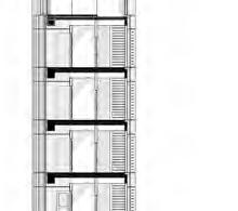
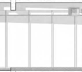
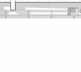
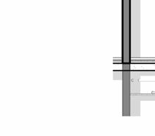
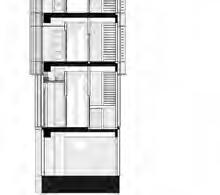
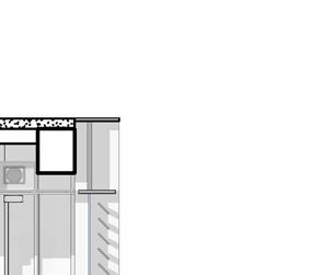
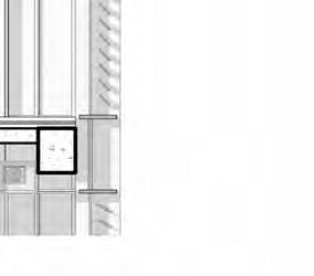
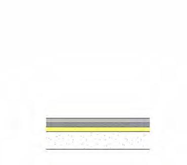
SECTIONAL DETAILS
ELEVATION AND FACADE DETAILS
REFLECTED CEILING PLANS
STRUCTURAL FRAMING PLANS
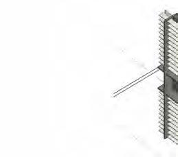
DETAILS
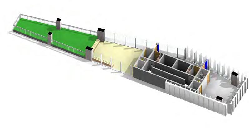
COORDINATED MODEL

STRATEGIC DEFINITION
Understanding and identifying the client requirement
Checking the feasibility of the project based on the same
PREPARATION AND BRIEFING
Throughly studying the BEP from Client. Listing down all the BIM uses relevant to the project. Understanding the purpose of MIDP Matrix
CONCEPT DESIGN
Setting up the necessary project details, grids and levels in revit. Working on Conceptual Massing option and generating schedules for the floor area, Creating sheets, axonometric views and rendering
DESIGN DEVELOPMENT
Creating & naming Architectural and Structural system families, Based on BEP: Setting up Worksets, Linking relevant files and Modelling the elements based on the LOD required at this stage. Integration of Coordination model and interference checking. Creating client and Government package documentation.
TECHNICAL DESIGN
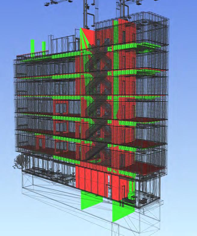
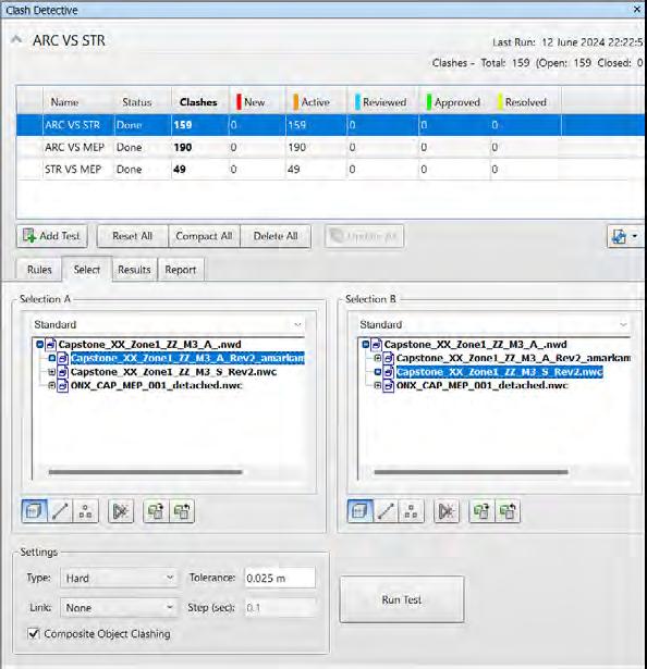
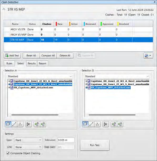
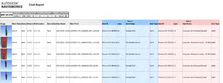
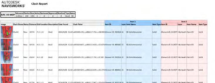
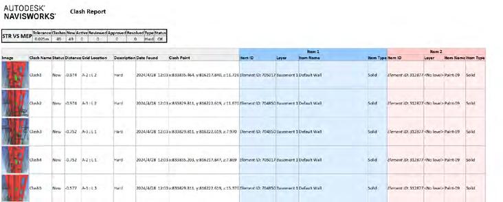
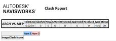
Setting up Coordination views, Performing Clash detection and then clashes resolution in Navisworks. Developing the Design as per LOD required. Creating Schedules and setting up sll the required Sheets to create Technical package
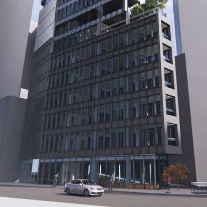
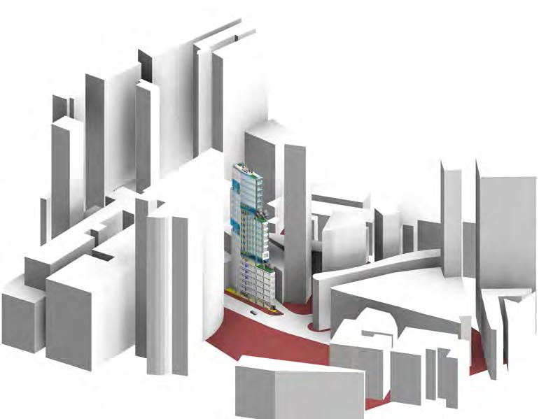
PROJECT OVERVIEW
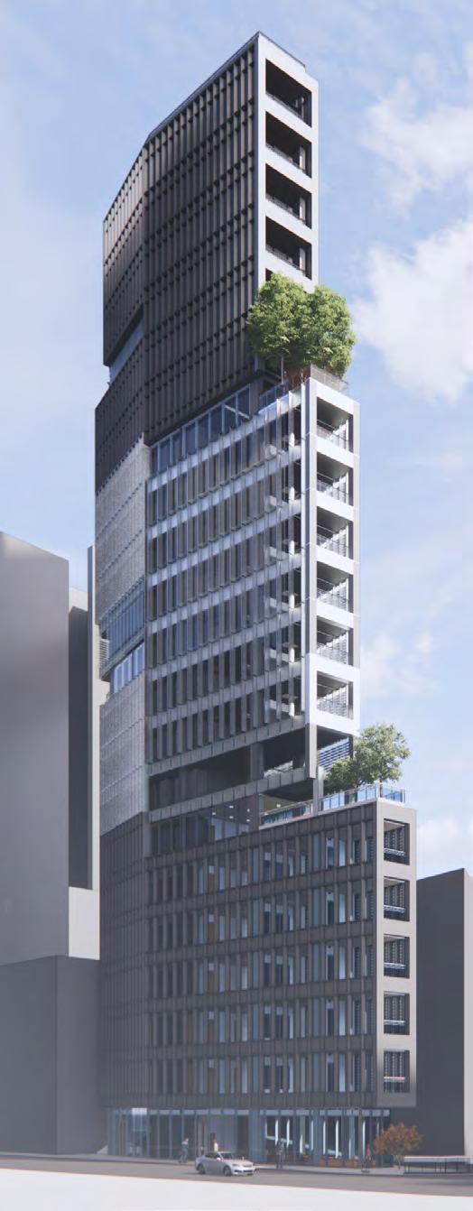
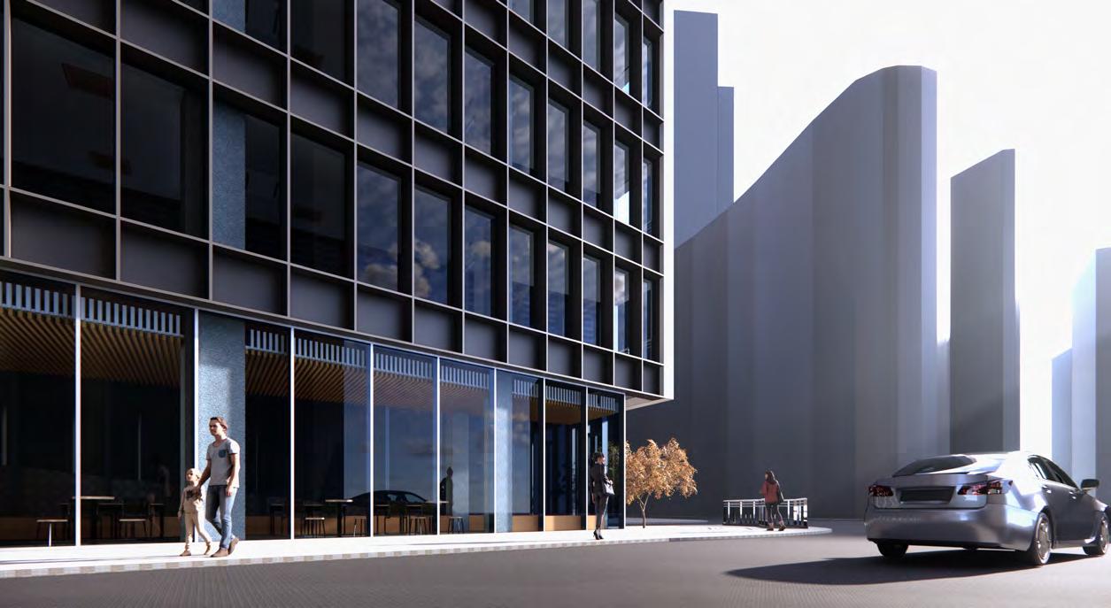
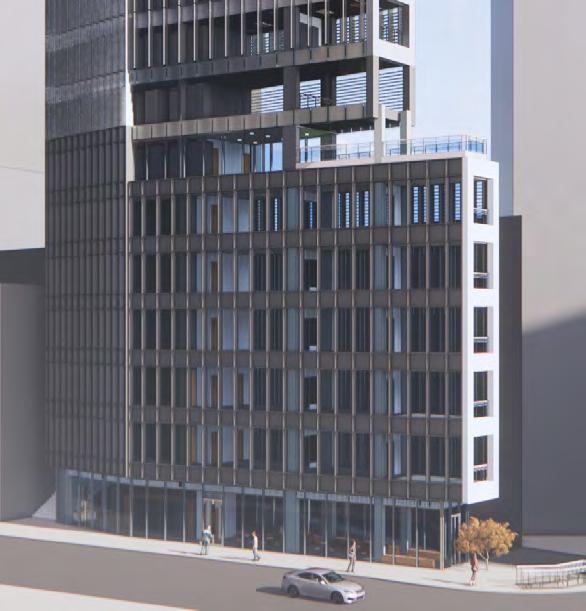
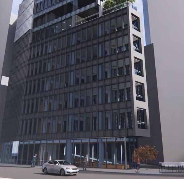
To redevelop the existing high-rise located at the intersection of wellington st. And queens road central in the central district of hong kong island.
The existing building, built in the 70’s doesn’t maximize the current allowed GFA of the plot.
The owner is looking at possibility of another building volume that can provide a better ROI while a landmark in a critical Urban point, by utilizing maximum GFA.
DETAILS OF THE PROJECT
Client: Enzyme Oneistox APD Ltd.
Typology : Mixed Use high rise building (Office & Serviced apartments)
Site Area :203.7 sqm.
Currently utilised GFA: 1430 sqm.
Max. Available GFA :2810.5 sqm.
Max. Site Occupation permissible: 162.7 sqm
Maximum no. of storey’s: 21
FAR : 13.8
Architects: Zone 1/ Zone 2/ Zone 3
Engineers: Zone 1/ Zone 2/ Zone 3
MEP, Site and Landscaping
OBJECTIVE
Tools used for Project :
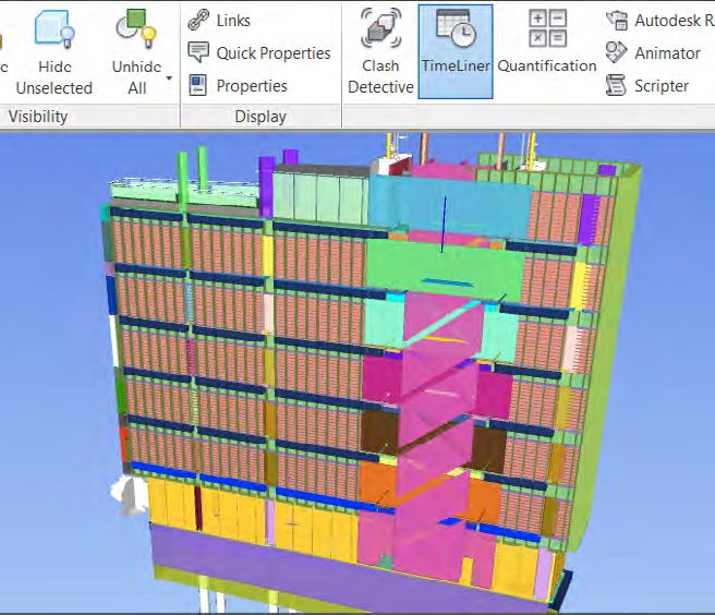
For Modeling - Revit For Clash Test - Navisworks For Renders & Presentation - Revit & Enscape
Level of Detail : LOD 350
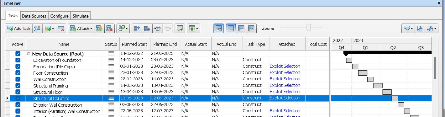
MANUFACTURING AND CONSTRUCTION
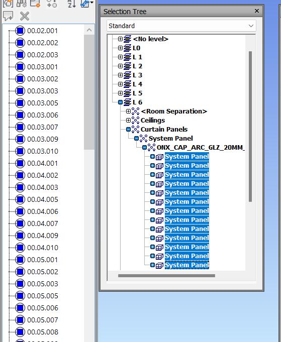
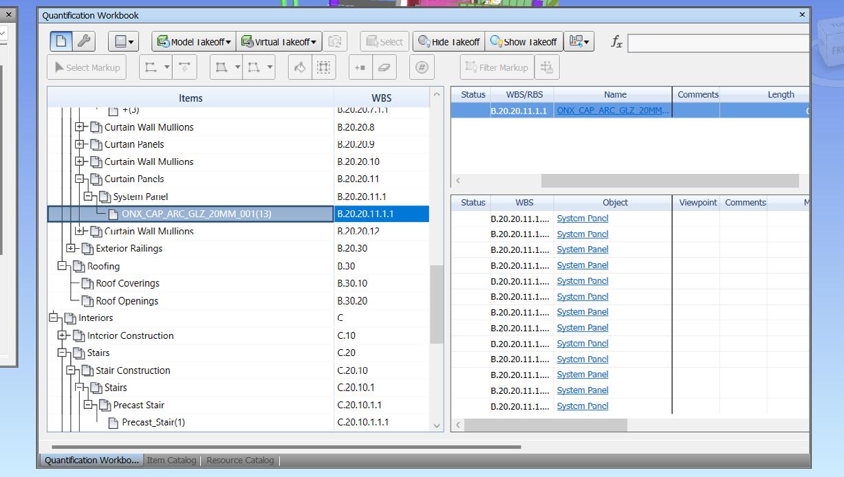
Preparing a tentative work schedule. Creating shared parameter and adding ID to model elements in revit and performing 3D Simulation in Navisworks and generating quantities in Navisworks for building elements.
HANDOVER & CLOSE OUT
Getting a rough idea of what handover process is. Post occupancy evaluation is done, defects are rectified and the project handed over to client for usage.
IN
USE

Understanding facility management and other services to determine and analyse the building performance post occupancy

Royal Institute Of British Architects

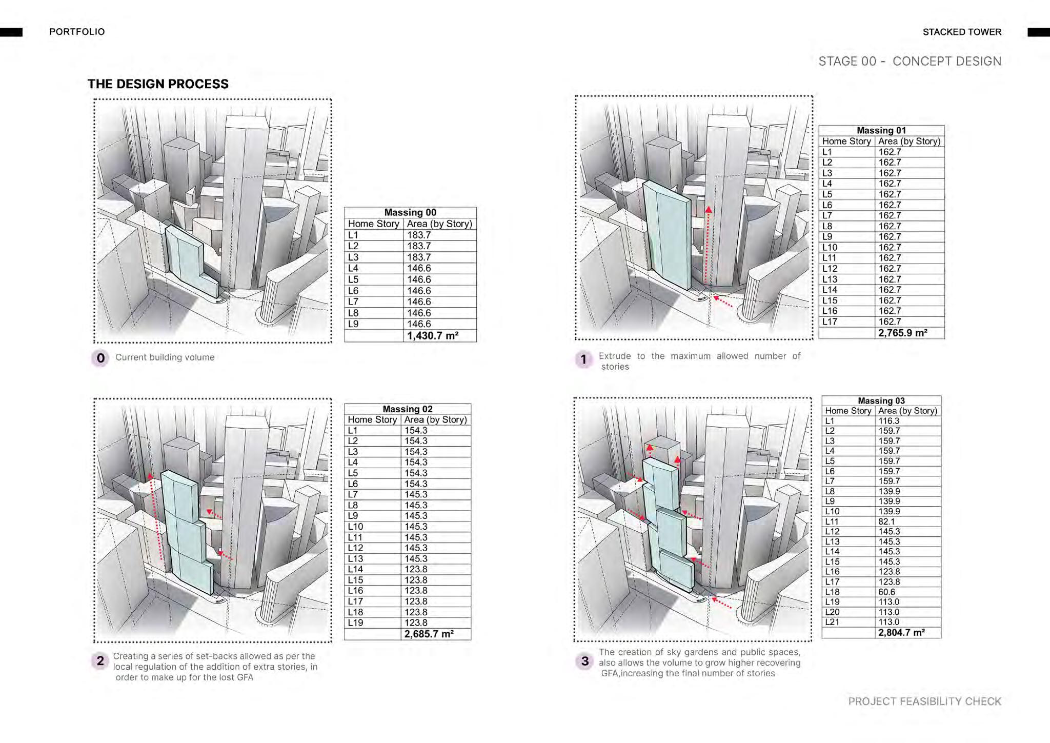
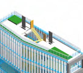
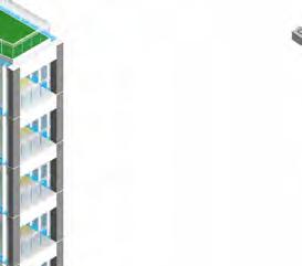
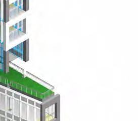
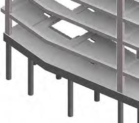
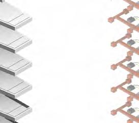
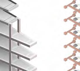
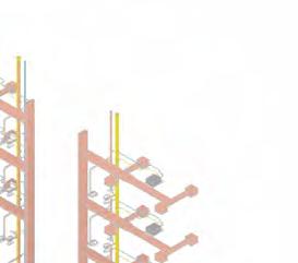
The project aims to explore the potential for incorporating a series of setbacks in compliance with local laws. These setbacks would enable the addition of more stories to the building. By Incorporating sky gardens and public spaces that expand upwards and recover GFA, the total number of storeys could be increased to 21.