BOOSTER ARIA-OLIO
AIR-OIL BOOSTER
LUFT - ÖL BOOSTER
SERIE - SERIES - BAUREIHE

MF
BOOSTER ARIA-OLIO AIR-OIL BOOSTER
LUFT - ÖL BOOSTER
SERIE - SERIES - BAUREIHE MF
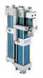
Canotto in lega leggera anodizzata
Anodized light alloy tube
Hochdruckzylindergehäuse in Leichtmetall anodisiert
Stelo in acciaio C40 cromato a spessore
Hard chromium plated C40 steel piston rod
Kolbenstange in Stahl C40 hartverchromt
Boccola bronzo BS ZN5 UNI 7013
Bronze bushing BS ZN5 UNI 7013
Führungsbüchse in Bronze BS ZN5 UNI 7013
Guarnizioni alta pressione in poliuretano
Polyurethan high pressure seals
Hochdruckverdichtungen in Polyurethan
Testate in lega leggera pressocolata
Die casted light alloy end caps
Zylinderköpfe in Leichtmetall-Guß
Camicia in lega leggera anodizzata
Anodized light alloy body
Zylindergehäuse in Leichtmetall anodisiert
Pistone in alluminio con guarnizione in poliuretano
Aluminum piston with polyurethane seal
Kolben aus Aluminium mit Polyurethan-Dichtung
Booster aria-olio
Il booster aria-olio Alfamatic serie MF è una apparecchiatura composta da un cilindro pneumatico e da una camera di alta pressione.
L’alta pressione che si genera sul fluido idraulico è direttamente proporzionale al rapporto tra l’area del pistone e quella dello stelo.
• Funziona in assenza di lubrificazione
• Possibilità di orientare le connessioni del liquido su 360 gradi
• Deceleratori di fine corsa
Air-oil booster
Alfamatic air-oil booster series MF is a unit composed of a pneumatic cylinder and an high pressure chamber.
The high pressure generated on the hydraulic fluid in the chamber is directly proportional to ratio between the areas of the piston and the piston rod.
• Works without lubrication

• Possibility to turn fluid connections around 360 degrees
• End stroke deceleration
Luft - Öl booster
Alfamatic-Luft - Öl booster der Baureihe MF besteht aus einem Pneumatikzylinder und einer Hochdruckkammer. Der in der Hochdruckkammer in der Druckflüssigkeit entstehende Druck ist direkt proportional dem Luftdruck multipliziert mit dem Übersetzungsverhältnis, d.h. Flächenverhältnisses zwischen Pneumatikkolben und Kolbenstange.

• Wartungsfreier Betrieb
• Freie Wahl durch Druckanschlußposition über 360 Grad
• Endlagendämpfung
Su richiesta versione Atex On request Atex version Auf Wunsch Atex Version II 2G Ex h IIB T6 Gb 2
Booster Tipo - Booster Type - Booster Typ: MF 102-103
Booster Tipo - Booster Type e - Booster Typ: MF 122-123-162-163-164-203-204
Diagrammi pressione - Pressure diagrams - Druck-Diagramm
Diagramma corsa/volume liquido - Stroke fluid/volume diagrams - Hub/Volumen Diagramm
Corsa - stroke - Hub mm


Volume liquido
alta pressioneHigh pressure fluid volume Hochdruck-Volumen cm 3
Pressione liquidoFluid pressureFlüssigkeits-Druck bar Pressione aria - Air pressure - Luftdruck bar 160 140 120 100 80 60 40 20 0 0 0 0 1 50 50 2 100 100 3 150 150 200 4 200 250 5 250 6 7 160 300 180 350 140 250 120 200 100 150 80 100 60 50 40 20 0 0 400 350 300 250 200 150 100 50 0 0 1 2 3 4 5 6 7 MF 102 MF 102 MF 103 MF 103 MF 122 MF 122 MF 123 MF 123 MF 162 MF 162 MF 163 MF 163 MF 164 MF 164 MF 203 MF 203 MF 204 MF 204 3
CARATTERISTICHE TECNICHE DIMENSIONALI TECHNICAL FEATURES AND DIMENSIONS
R: Aria - Air - Luft
S: Liquido bassa pressione - Low pressure fluid - Druckanschluß Niederdruck-Flüssigkeit
T: Liquido alta pressione - High pressure fluid - Druckanschluß Hochdruck-Flüssigkeit
(1) Per corsa 200mm: L= L(1)+50. Valido per tutti i modelli. Stroke 200mm: L= L(1) +50. Valid for all models. Hub 200 mm: L= L(1) +50. Gültig für alle Modelle.
Alesaggio Bore size Kolben Ø Stelo Piston rod Kolbenstange Ø Corsa Stroke Hub Rapporto di moltiplica Multipler ratio Übersetzungsverhältnis Pressione liquido aria a 6 bar Fluid pressure air at 6 bar Flüssigkeits- druck bei 6 bar Luftdruck Volume liquido corsa 150 mm Fluid volume stroke 150mm Flüssigkeits-Volumen bei 150 mm Hub Rendimento Efficiency Wirkungsgrad mm mm mm bar cm3 η MF 102 100 22 150 20,66 124 49 0,9 MF 103 100 30 150 11,11 67 91 0,9 MF 122 125 22 150 32,28 194 49 0,9 MF 123 125 30 150 17,36 104 91 0,9 MF 162 160 22 150 52,89 317 49 0,9 MF 163 160 30 150 28,44 171 91 0,9 MF 164 160 40 150 16,00 96 163 0,9 MF 203 200 30 150 44,44 267 91 0,9 MF 204 200 40 150 25,00 150 163 0,9 Alesaggio Bore size Kolben Corsa Stroke Hub A B E F G I L(1) M N P R S T Ø mm mm mm mm mm mm mm mm mm mm MF 102 - MF 103 Ø 100 150 70 115 20 40 42 295 580 115 90 M10 1/2" 1/2" 1/2" MF 122 MF 123 Ø 125 150 90 134 25 40 42 295 585 140 110 M12 1/2" 1/2" 1/2" MF 162 MF 163 MF 164 Ø 160 150 90 134 25 46 44.5 330 625 180 140 M16 3/4" 1/2" 1/2" MF 203 MF 204 Ø 200 150 90 134 25 46 44.5 330 625 220 175 M16 3/4" 1/2" 1/2"
TECHNISCHE DATEN
A B R R S S E F I L(1) G G T N ±0,1 M P 4
UND ABMESSUNGEN
FISSAGGI FIXINGS BEFESTIGUNGEN
Tipo - Type - Typ: FL
Flangia in acciaio zincato.
Flange in galvanized stell.
Flansch in Verzinkt Stahl.
Tipo - Type - Typ: PB
Piedino basso in lega leggera anodizzata. Low foot mounting in anodized light alloy. Füße in Leichtmetall vergütet.
Serbatoio - Reservoir - Ölbehälter: SN-01
Camera liquido Fluid chamber Flüssigkeitskammer
MF_FL_PB
dis. n° Ricavato da dis. n° Aterminidileggeciriserviamolaproprietàdiquestodisegnocondivietodiriprodurloocomunquedirenderlonotoaterzi senza nostra autorizzazione
PRODOTTO Valorietolleranzenonspec. Lungh.ediam.±0,1 Smussi0,2x45° Angoli±1° Raggir=0,2 RugositàRaUNI-4600
Materiali
• Corpo trasparente in Plexiglass
• Testata in lega leggera
Modalità di installazione
MF_FL_PB
Serbatoio - Reservoir - Ölbehälter: SN-12 -14
Tappo di sfiato Breather cap Entlüftungsschraube
Il booster aria-olio tipo MF con serbatoio solidale deve essere installato in orizzontale; il serbatoio va posizionato sulla parte più alta dell’impianto.
Materials
• Plexiglass transparent body
• Light alloy end cap
Installation
Air-oil booster MF with attached oil reservoir must be installed horizzontally.
Oil reservoir has to be fixed at higher position of equipment.
Material
• Rohr in Plexiglass transparent
• Kopfflansch in Leichtmetall
Montagehinweis:
Der Luft - Öl Booster Typ MF mit Zusatzbehälter muß waagrecht montiert werden, der Ausgleichsbehälter muß dabei in der höchsten Position montiert werden.
Connessione aria Air connection Druckluftanschluß
Livello max
Max level Max. Ölstand

Livello minimo Min level Min. Ölstand
Tappo scarico olio Oil drain plug Öl-Ablaßschraube
Tappo caric. olio Oil filler cap Öl-Einfüllschraube
Materiali
• Tubo trasparente in plexiglas
• Protezione in acciaio
• Testate in lega leggera
Modalità di installazione
Il booster aria-olio tipo MF con serbatoio SN può essere installato in qualsiasi posizione. Il serbatoio deve essere sempre posizionato nella parte più alta dell’impianto.
Materials
• Plexiglass transparent tube
• Steel guard
• Light alloy end caps
Installation
Air-oil booster type MF with SN reservoir can be fixed in any position. Oil reservoir has always to be fixed at higher position of equipment.
Material
• Rohr in Plexiglas transparent
• Schutzgehäuse in Stahl
• Kopfflansche in Leichtmetall
Montagehinweis:
Der Luft - Öl booster MF mit Zusatzbehälter SN kann in beliebiger Position montiert werden. Der Ausgleichsbehälter muß jedoch an der höchsten Stelle des Systems montiert werden.
Connessione gruppo MF
Connection MF group
Anschluß Druckübersetzer
Camera liquido Fluid chamber Flüssigkeitskammer
Pressione max-6 bar
Maximum pressure-6 bar Max. Luftdruck 6 bar
Alesaggio Bore size Kolben Ø B C D E F M FV 100 CN 100 mm 12 170 150 90 14 115 FV 125 CN 125 mm 16 205 180 110 18 140 FV 160 CN 160 mm 20 260 228 140 22 180 FV 200 CN 200 mm 20 300 268 175 22 220 Alesaggio Bore size Kolben Ø B C D E F G M PB 100 CN 100 mm 43 13 73 6 90 14 115 PB 125 CN 125 mm 52 18 91 8 100 18 140 PB 160 CN 160 mm 62 13 115 9 130 22 180 PB 200 CN 200 mm 62 38 135 12 170 22 220 Volume Volume Volumen cm3 V BB BD BE BF BG BH SN-12100 412 53 1/4” 148 60 100 8,5 75 SN-14160 653 53 1/4” 208 60 100 8,5 75 M C D E F B C B F G D E M TIPO PRODOTTO Valorietolleranzenonspec. Lungh.ediam.±0,1 Smussi0,2x45° Angoli±1° Raggir=0,2 RugositàRaUNI-4600 Data Nome Disegnato Controllato Scala Foglio1di1 ISO E Qta. : MATERIALE DIMENSIONI TRATTAMENTO FINITURA PESO : 20010SanGiorgiosuLegnano(Mi)-Italy ViaMagenta,25 tel. +39 0331 406911 www.alfamatic.com info@alfamatic.com Nr. DISEGNO Sostituisce
1:5
CODICE MAT. x ( ) DESCRIZIONE M C D E F B C B F G D E M TIPO
Data Nome Disegnato Controllato Scala Foglio1di1 ISO E Qta.
MATERIALE DIMENSIONI TRATTAMENTO FINITURA PESO : 20010SanGiorgiosuLegnano(Mi)-Italy ViaMagenta,25 tel. +39 0331 406911 www.alfamatic.com info@alfamatic.com Nr. DISEGNO INDICE DIMODIFICA PARTICOLARE Sostituisce dis. n° Ricavato da dis. n° Aterminidileggeciriserviamolaproprietàdiquestodisegnocondivietodiriprodurloocomunquedirenderlonotoaterzi senza nostra autorizzazione 1:5
:
CODICE MAT. x ( x x DESCRIZIONE
1/2”G 1/8”G Ø 55 BH BE ØBF BB V BG BD 120 1/2”G 1/8”G Ø 55 BH BE ØBF BB V BG BD 120 1/2”G 1/8”G Ø 55 BH BE ØBF BB V BG BD 120 1/2”G 1/8”G Ø 55 BH BE ØBF BB V BG BD 120 1/2”G 1/8”G Ø 55 BH BE ØBF BB V BG BD 120 5
ESEMPI APPLICATIVI E COLLEGAMENTI EXAMPLES OF APPLICATIONS AND CONNECTIONS ANWENDUNGSBEISPIELE
1
Impianto - Circuit - Schema 2
Comando cilindri idraulici a semplice effetto (ritorno con molla meccanica).
Control for single acting hydraulic cylinders (return with mechanical spring).
Schaltbild mit einfachwirkenden Hydraulikzylindern (Kolben mit Federrückzug).
Impianto - Circuit - Schema
Comando cilindri idraulici a doppio effetto (ritorno con molla idropneumatica)
La spinta di ritorno dei cilindri idraulici si regola variando la pressione dell’aria nel serbatoio B (max 6 bar).
3
Control for double acting hydraulic cylinders (return with hydro-pneumatic spring)
The return thrust of hydraulic cylinders can be regulated by changing the air pressure in reservoir B (6 bar max).
Impianto - Circuit - Schema
Comando cilindri idraulici a doppio effetto
• Corsa di avvicinamento A a bassa pressione
• Corsa di lavoro B ad alta pressione
Ciclo di lavoro
• Corsa di avvicinamento A: il liquido passa direttamente dal serbatoio A al cilindro H
• Corsa di lavoro B: intervento del booster aria-olio MF
• Ritorno cilindro H: il liquido rientra nel booster aria-olio MF e nel serbatoio A.
Control for double acting hydraulic cylinders
• Low pressure approach stroke A
• High pressure working stroke B
Working cycle
• Approach stroke A: fluid goes directly to cylinder H from reservoir A
• Working stroke B: starting of MF Air-oil booster
• Return cylinder H: fluid goes back to air-oil booster MF and to reservoir A.
Schaltbild mit doppeltwirkenden Hydraulikzylindern (Rückhub durch hydropneumatische Feder)
Die Rückhubkraft läßt sich durch den Luftdruck im Behälter B regulieren (max. 6 bar).
Note
• I serbatoi e i fissaggi (flangia e piedino) vanno ordinati a parte
• Il booster aria-olio e i serbatoi vengono forniti senza liquido (olio)
• È possibile fornire serbatoi tipo SN-12 e SN-14 con capacità superiori
• È consigliato l’utilizzo di oli idraulici con viscosità 3°
E a 50 °C
• Utilizzare aria compressa filtrata max 6 bar
Schaltbild mit doppeltwirkenden
Hydraulikzylindern
• Eilhub A mit niedrigem Druck
• Arbeitshub B mit hohem Druck
Arbeitsfolge
• Eilhub A: die Flüssigkeit strömt direkt vom Behälter A zum Zylinder H
• Arbeitshub B: Öldruckversorgung in Zylinder H über Luft - Öl booster
• Rückhub des Zylinder H: das Öl aus Behälter B drückt den Kolben zurück und dabei die Flüssigkeit in den Luft - Öl booster MF und in den Behälter A zurück.
Notes
• Reservoirs and mounting (flange and foot) have to be ordered apart
• Air-oil booster and reservoirs are supplied without oil
• It is possible to supply oil reservoirs type SN 12/14 with bigger capacity
• We suggest to use hydraulic oil with viscosity 3° E at 50 °C
• Use filtered air maximum 6 bar
Anmerkung
• Die Behälter und Befestigungen (Flansch oder Füße) sind separat zu bestellen
• Der Luft - Öl booster und die Behälter werden ohne Ölfüllung geliefert
• Die Behälter SN-12 und SN-14 sind auch mit größeren Volumen lieferbar
• Wir empfehlen Hydrauliköl mit einer Viskosität von 3°
E bei 50 °C
• Nur gefilterte Druckluft mit max 6 bar verwenden
MF SN - 01 H1 H2 SN - 12100 SN - 14160 SN - 01 MF H1 H2 SN-12100 SN-14160 SN-12100 SN-14160 NF A B H A B A B MF SN - 01 H1 H2 SN - 12100 SN - 14160 SN - 01 MF H1 H2 SN-12100 SN-14160 SN-12100 SN-14160 NF A B H A B A B MF SN - 01 H1 H2 SN - 14160 SN - 01 MF H1 H2 SN-12100 SN-14160 SN-12100 SN-14160 NF A B H A B A B 6
Elementi dell’impianto - Circuit components - Stückliste
Elementi dell’impianto - Circuit components - Stückliste
Elementi dell’impianto - Circuit components - Stückliste
Note
In tutti gli esempi considerati è stato adottato un booster aria-olio con corsa standard (150 mm); se si richiede un booster aria-olio con una corsa diversa, sostituire il valore 150 con la corsa richiesta in mm (100 - 200 - 250 - 300).
Esempio: booster aria-olio MF 102 - corsa 200 mm
Codice = MF 102 - 200
Notes
A standard air-oil booster with 150 mm standard stroke has been employed in all above described solutions. When an air-oil booster with different stroke is requested, replace the 150 value with the requested stroke in millimetre (100-200-250-300).
Example: air-oil booster MF 102 - stroke 200 mm Code = MF 102 - 200
Anmerkung
Alle dargestellten Beispiele beziehen sich auf Luft - Öl booster mit Standardhub (150 mm); falls ein Luft - Öl booster mit abweichenden Hub gewünscht wird, ist der Wert 150 durch den gewünschten Hubwert in mm zu ersetzen (100-200-250-300).
Beispiel: Luft - Öl booster MF 102 - Hub 200 mm Bestellbezeichnung = MF 102 - 200
Quantità Quantity Stückzahl n° Codice per l’ordinazione Ordering code Bestell-Nr Booster aria-olio - Air-oil booster - Luft - Öl Booster 1 MF 102 -150 Eventuali fissaggi - Eventual fixings - Evtl. Befestigungsschraube 1 FV100CN Serbatoio - Reservoir - Behälter 1 SN - 01 Quantità Quantity Stückzahl n° Codice per l’ordinazione Ordering code Bestell-Nr Booster aria-olio - Air-oil booster - Luft - Öl Booster 1 MF 163 -150 Eventuali fissaggi - Eventual fixings - Evtl. Befestigungsschraube 2 PB160CN Serbatoio - Reservoir - Behälter 1 SN - 01 Serbatoio - Reservoir - Behälter 1 SN - 14160 Quantità Quantity Stückzahl n° Codice per l’ordinazione Ordering code Bestell-Nr Booster aria-olio - Air-oil booster - Luft - Öl Booster 1 MF 162 - 150 Eventuali fissaggi - Eventual fixings - Evtl. Befestigungsschraube 2 PB160CN Serbatoio - Reservoir - Behälter 2 SN - 14160
I CATALOGHI DISPONIBILI: AVAILABLE CATALOGUES: VORHANDENE KATALOGE:
Presse pneumoidrauliche
Pneumo-hydraulic presses

Hydropneumatische Pressen
ALFAMATIC srl
20034 S. Giorgio su Legnano (MI) - Italy
Via Magenta 25
Tel. +39 0331.40.69.11
Fax +39 0331.40.69.70
E-mail: info@alfamatic.com
Presse pneumoidrauliche ad azionamento manuale
Manually operated pneumo-hydraulic presses


Manuell Gesteuerte Hydropneumatische Pressen
Sistemi per il controllo del processo di pressatura
Pressing process control systems


Überwachungssysteme des Pressvorgangs
Cilindri pneumoidraulici
Pneumo-hydraulic cylinders

Zylinder für Pneumoidraulic
Booster aria-olio
Air-Oil booster
Luft - Öl booster
Cilindri elettrici
Electric cylinders
Elektrozylinder
www.alfamatic.com
Scansiona il QR Code e visita il nostro sito!
Scan the QR Code and visit our website!
Scannen Sie den QR Code und besuchen Sie unsere Website!

Distributore - Distributor - Vertreiber
e le immagini possono cambiare senza preavviso Technical data and images can change without prior notice Sowohl die technischen Daten als auch die Abbildungen können ohne vorherige Mitteilung geändert werden
I dati tecnici
