

Fire Safety Study (FSS)
Project Name: Orana Battery Energy Storage System (BESS)
Job Number: 8607
Date: 10 July 2025
Client: Akaysha Energy Pty Ltd.
Revision 09
Orana
01 08/02/2024 Prepared by:
Javier Piedrahita - PE0003748
02 08/03/2024 Prepared by:
Javier Piedrahita - PE0003748
03 14/06/2024 Prepared by:
Javier Piedrahita - PE0003748
Approved by: Ian Moore - PE0003103
Approved by: Ian Moore - PE0003103
Approved by: Ian Moore - PE0003103 04 25/09/2024
Prepared by:
Javier Piedrahita - PE0003748
Approved by: Ian Moore - PE0003103 05 06/11/2024 Prepared by:
Javier Piedrahita - PE0003748
06 28/11/2024 Prepared by:
Javier Piedrahita - PE0003748
07 16/04/2025
Prepared by:
Javier Piedrahita - PE0003748
08 14/05/2025 Prepared by:
Javier Piedrahita - PE0003748
09 10/07/2025 Prepared by:
Javier Piedrahita - PE0003748
Approved by: Ian Moore - PE0003103
Approved by: Ian Moore - PE0003103
Approved by: Ian Moore - PE0003103
Approved by: Ian Moore - PE0003103
Approved by: Ian Moore - PE0003103


INTRODUCTION

NJM Design has been engaged by Akaysha Energy Pty Ltd. to undertake a Fire Safety Study (FSS) for the Orana Battery Energy Storage System (BESS) located in Dubbo Region at New South Wales (NSW) 2820
Orana BESS is a 415MW/1660MWh project that utilises Tesla Megapack 2XL product and connects to Wellington 330kV terminal station via underground cable (see Figure 1 below).
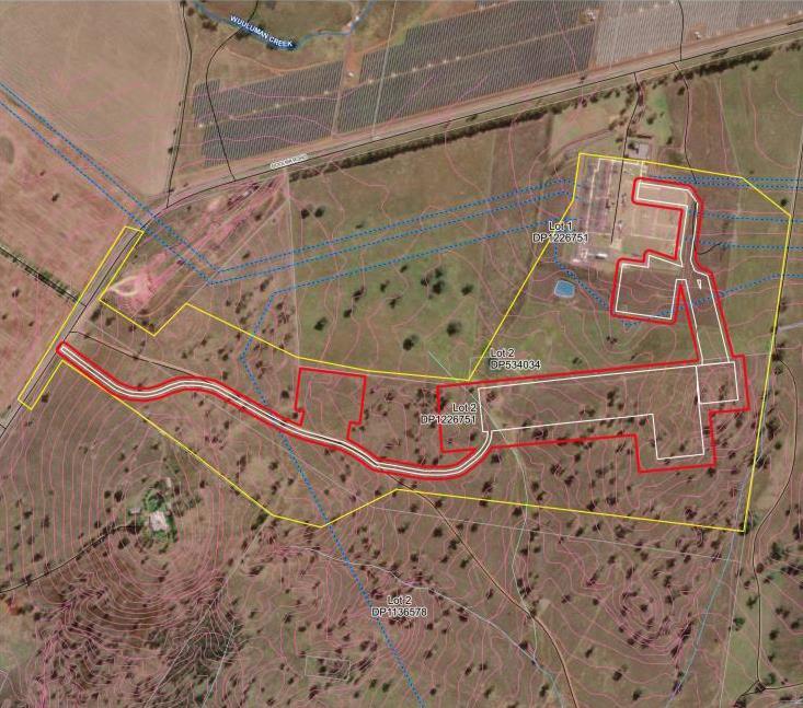
Orana BESS facility is as presented in the plans in Appendix A. The Megapack is a modular, fully integrated, ACcoupled industrial Battery Energy Storage System (BESS).
This Study formulates part of an integrated assessment process for safety assurance of development proposals, which are potentially hazardous. The assessment is based on the methodology outlined in the Hazardous Industry Advisory Papers (HIPAPS).
The process is shown diagrammatically in Figure 2
Orana Battery Energy Storage System (BESS) Page 5 of 112
Figure 1: Orana BESS – General Location/Site plan.

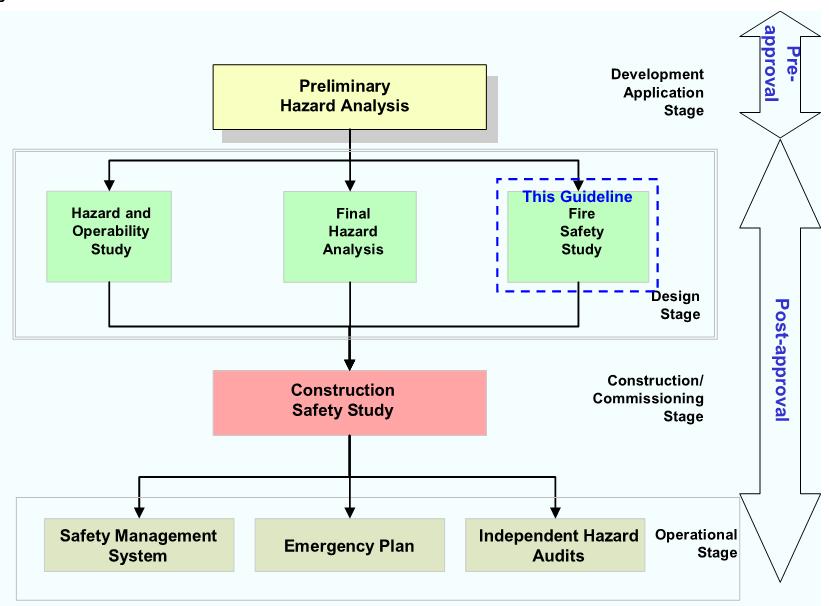
2: The Hazards-Related Assessment Process
Several Hazardous Industry Advisory Papers (HIPAPS) have been published to assist stakeholders in implementing the process, i.e.:
◼ No.–1 - Industry Emergency Planning Guidelines.
◼ No.–2 - Fire Safety Study Guidelines.
◼ No.–3 - Environmental Risk Impact Assessment Guidelines.
◼ No.–4 - Risk Criteria for Land Use Planning.
◼ No.–5 - Hazard Audit Guidelines.
◼ No.–6 - Guidelines for Hazard Analysis.
◼ No.–7 - Construction Safety Studies.
◼ No.–8 - HAZOP Guidelines.
◼ No.–9 - Safety Management System Guidelines.
◼ No. –0 - Land Use Safety Planning (Consultation Draft).
The studies detailed in the HIPAP papers involve case-specific hazard analyses and design of fire safety arrangements to meet those hazards. The approach is particularly important where significant quantities of hazardous materials as is the case with BESS units involved.
The review of the risks will be consistent with fire risk assessment techniques for Hazardous Industry Planning Advisory Paper 2 (HIPAP 2).
6 of 112
Figure


MAIN FINDINGS AND RECOMMENDATIONS
The findings and recommendations listed in this section have been gathered based on the assessment developed in this document and the advice of the stakeholders involved
Akaysha Energy Pty Ltd., as the developer of the projects has agreed to comply with the below requirements to achieve the required level of safety (refer to Appendix K).
The final findings and recommendations are the following:
1. The design of the BESS units is acceptable and covers all fire initiation and fire spread risks to the degree necessary given:
◼ The compliance with AS2067 separation distances for transformers (see sections 7.2.1 and 7.2.2).
◼ The provision of Test UL9540A to Unit Level test of the Megapack 2 (see Appendix G and Appendix H).
◼ The provision of a destructive test of the Megapack 2 (see Appendix G and Appendix H).
◼ Fire spread analysis for buildings (Section 7).
2. The proposed installation procedures and Units have design and requirements that address the issues raised by the Victorian Big Battery (VBB) fire (refer to Appendix E).
3. The risk of fire development and spread is no worse than that posed by existing utility infrastructure in the community or the adjacent buildings in the community.
4. All equipment is Scada Alarmed and will allow automatic notification to the operators, who will proceed according to the Emergency plan and the protocols.
5. Fire spread to adjacent allotments would not be predicted to occur, based on the distances from the subject site’ equipment/structures surpass the clearances specified by the NCC and the Australian standards. This is confirmed by the following:
◼ Fire spread analysis performed in Section 7.2 for Megapack 2XL and transformers. The critical heat flux criteria were met, as the adjoining structures and equipment do not receive a critical heat flux for failure. The clearances between equipment as per Appendix A are as follows:
Table 1: Clearances to maintain between equipment

Equipment 1
2
◼ Previous fire events occurred to two versions of the Tesla Megapack (i.e., Bouldercombe BESS and Elkhorn BESS in Section 6), where fire remains limited to the affected Megapack and no adjoining structures and equipment is affected without the provision of extinguishment agents.
◼ The destructive test to the BESS Unit demonstrated fire spread is limited to the affected Megapack and to not all the battery module bays. Adjoining Megapacks located to 6ft remained unaffected (see Appendix G and Appendix H)
6. Fire spread between Tesla Megapacks is not expected if any of them reaches flashover, Orana BESS design proposes a separation of 2,547mm between Megapacks 2XL facing each other, which exceeds and complies the distances proposed by the equipment manufacturer (i.e., 2,440mm); a clearance of 230mm between back-toback Megapacks 2XL as required by the manufacturer, and a sideway clearance of 5,050mm surpassing the manufacturer’s requirement (i.e., 150mm)
Furthermore, flashover is not expected to happen due to the fire safety measures, which will shut down the BESS or activate safety procedures to delay a possible battery-runaway failure and warn staff to perform the required maintenance before a battery catches fire. This is supported by the Test UL9540A to Unit Level test to the Megapack 2 (see Appendix G and Appendix H).
The fire safety measures provided will be the following:
◼ Overpressure vents/Explosion control system: The overpressure vents are designed to open to a lower pressure than the strength capacity of the BESS enclosure. Hence, the overpressure vents will open before the integrity of the enclosure is at risk. A pressure safety factor higher than 2 is provided
◼ Remote shutdown provisions.
◼ Electrical fault protection devices: The MP2/2XL have several passive and active safety control mechanisms installed within the battery module circuit and distribution circuit that would be available to interrupt a fault current. These include the Battery module overcurrent protection, Inverter DC protection, Inverter AC protection, the Ground fault protection, and lightning strike protection, and an internal safety circuit called an enable circuit (also known as HVIL - high-voltage interlock loop) that shuts down all major power components when other faults are detected [1]
◼ Battery Management system (BMS): The BMS is engineered to react to fault conditions in an autonomous manner, with safeguards built into the firmware. These fault conditions include, but are not limited to, overtemperature, loss of communication, over-voltage, and isolation. For instance, to prevent a cell overtemperature the TMS is enabled by the BMS to cool the cells/module. This action by the BMS (which is just one example of many ways the BMS can respond to a fault condition) can either prevent thermal runaway from occurring in the cell or prohibit the propagation of thermal runaway to adjacent cells. Depending on the severity of the fault condition, the BMS can automatically isolate the affected battery module temporarily (less severe fault) or it can permanently disconnect the module.

◼ Thermal management system (TMS): The thermal management system (TMS) provides a suitable operating temperature for MP2 using liquid cooling via a 50/50 mixture of ethylene glycol and water and R-134a refrigerant. The TMS contains a closed-loop liquid cooling system that circulates liquid coolant throughout the battery modules and power electronics to maintain an optimum operating temperature.
◼ Site Controller and Monitoring: The MP2/2XL has 24/7 remote monitoring, diagnostics, and troubleshooting capabilities, and also has a local Supervisory Control and Data Acquisition (SCADA) system. All faults are transmitted to a Tesla LOC, alerting them to off-normal conditions that may require corrective action, either through remote means or an in-person field service visit. This communication link is accomplished via the Tesla Site Controller (TSC). The TSC provides the single point of interface for the utility, network operator, and/or the customer’s SCADA systems to control and monitor the entire energy storage site.
7. Based on the preliminary fire modelling results (section 7.2) and review of the transformers location, Fire brigade intervention procedures are not considered required for a fire to a Megapack 2XL or to a Transformer:
◼ If the fire happens to a Megapack 2XL BESS, the equipment manufacturer indicates to Not use water and to allow the Megapack to burn completely [2]
◼ If the fire happens to a HV transformer, the HV transformer fire is allowed to burn out itself given that fire spread is not predicted. The clearances comply with AS2067, firewalls are provided between HV transformers in accordance with AS2067 (Figure 3, Figure 4, Appendix D), and the FDS model complied with the fire spread criteria (section 7.2)
◼ If the fire happens to a MV/SUT, the self-containment and the provision of enhanced protection will prevent to the degree necessary the risk of fire spread, given that the clearances are well above the requirements of the AS2067.
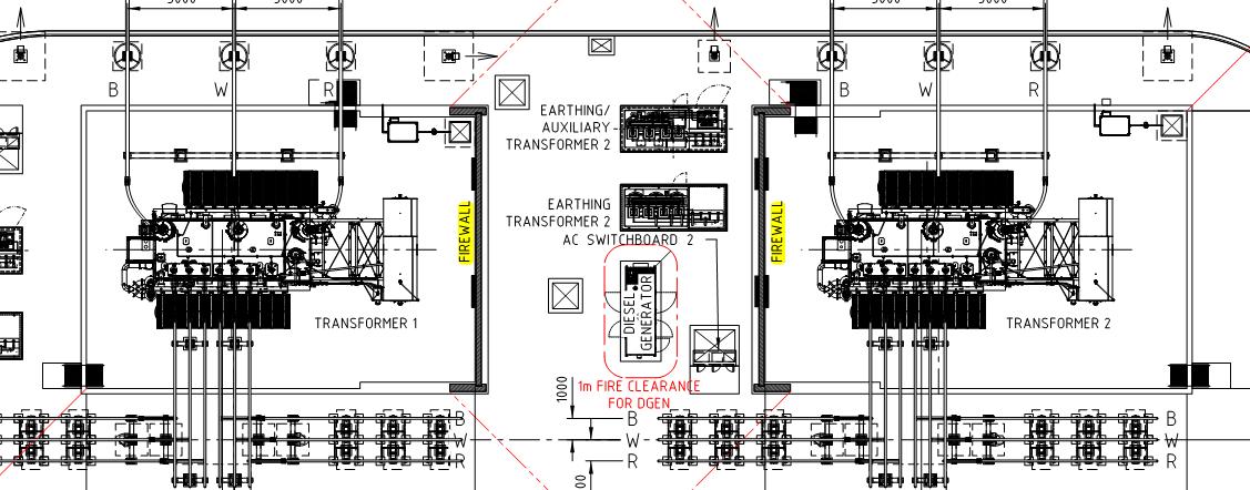
Figure 3: Firewalls between transformers (plan view).
Orana
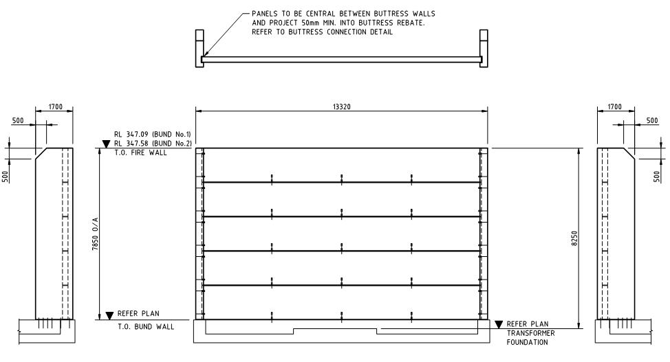
Figure 4: Firewalls between transformers (elevation).

8. Given a catastrophic failure of either the transformers or Tesla Megapacks 2XL, only the equipment on fire (e.g., transformers or Tesla Megapacks 2 XL) is expected to be lost and all surrounding equipment/buildings are expected to be able to work and not be physically affected by fire.
It is encouraged that attending fire fighters allow total burn out of any equipment within Orana BESS. Local firefighting authorities are encouraged to attend site to monitor and protect adjacent infrastructure and bushland when summoned by the staff (see Appendix G and Appendix H) Adjacent infrastructure and bushland may be cooled down if required with the use of the fire hydrant system.
Electrical consequences can occur where equipment/buildings associated with an equipment on fire can stop working. All equipment is expected to be protected by their own breakers to be isolated given the presence of fire, but further consequences and electrical backup measures are out of the scope of this report. Those electrical consequences must be addressed by another consultant separately
9. Water storage with not less 288kL will be provided at an entrance of the facility with a compliant hard stand and booster assembly in accordance with the latest CFA Guidelines Revision 4 [3] as follows:
◼ Water access points must be clearly identifiable and unobstructed to ensure efficient access.
◼ Static water storage tank installations must comply with AS 2419.1-2021: Fire hydrant installations – System design, installation and commissioning.
◼ The static water storage tank(s) must be an above-ground water tank constructed of concrete or steel.
◼ The static water storage tank(s) must be capable of being completely refilled automatically or manually within 24 hours.
◼ The static water storage tanks must be located at vehicle access points to the facility and must be positioned at least ten (10) metres from any structure
◼ The hard-suction point must be provided, with a 150mm full bore isolation valve equipped with a Storz connection, sized to comply with the required suction hydraulic performance.

◼ Adapters that may be required to match the connection are: 125mm, 100mm, 90mm, 75mm, 65mm Storz tree adapters with a matching blank end cap to be provided.
◼ The hard-suction point must be positioned within four (4) metres to a hardstand area and provide a clear access for emergency services personnel.
◼ An all-weather road access and hardstand must be provided to the hard-suction point. The hardstand must be maintained to a minimum of 15 tonne GVM, eight (8) metres long and six (6) metres wide or to the satisfaction of the CFA.
◼ The road access and hardstand must be kept clear at all times.
◼ The hard-suction point must be protected from mechanical damage (e.g., bollards) where necessary.
◼ Where the access road has one entrance, a ten (10) metre radius turning circle must be provided at the tank.
◼ An external water level indicator must be provided to the tank and be visible from the hardstand area.
◼ Signage indicating ‘FIRE WATER’ and the tank capacity must be fixed to each tank.
◼ Signage must be provided at the front entrance to the facility, indicating the direction to the static water tank.
10. A Fire hydrant system will be provided throughout the facility for fire brigade intervention procedures. Where any infrastructure or equipment is on fire, the fire brigade can use the fire hydrant system to cool adjoining areas/vegetation/infrastructure if required while the main fire extinguish itself.
11. The fire hydrant system will be provided in accordance with AS 2419.1-2021: Fire hydrant installations, Section 3.9: Open Yard Protection. The location of hydrants must be designed as follows:
◼ Be located not less than 27.0m from the HV transformers of the Substation.
◼ The hydrants will be located such that all infrastructure can be covered by at least 2 hydrants.
12. A containment and management plan of contaminated fire water runoff from the BESS is to be developed by the facility.
13. Given a fire to a Tesla Megapack 2XL, toxic gasses released are not expected to harm adjoining communities or fire brigade staff given the low concentrations released (refer to section 6.7 of this FSS) and use of the fire protective gear of the fire brigade staff (i.e., self-contained breathing apparatuses).
14. The access to the site is not expected to be prevented given that that there are multiple access entrances. The primary access is located at the South-West of the site via the access road; and there are two other access points which should be used as secondary means if the Primary access is compromised, these secondary accesses are located at the South and the East of the Site.
If a given fire/emergency prevents the access to the site via the main entry or alternative entrances. Access through the main entry will be provided via intercom, and all gates to alternative entrances are provided with 003-key padlocks to facilitate the access of the Fire Brigade.
The fire Brigade will also access accompanied by staff who is on site or will arrive to the site given an emergency, given that the fire brigade will only attend the site upon a call from the BESS staff.
15. Fire brigade and Staff intervention during an emergency is expected to be managed to the degree necessary given the following safety measures:
Orana Battery Energy Storage System (BESS)

◼ Provision of warning signs as per Clause 5.3.3 of FRNSW BESS Guideline [4] Some signage includes the following examples (not limited to):
◼ Exit signs.
◼ First aid firefighting equipment (fire hydrants, water storage tanks, fire extinguishers, etc.).
◼ Electrical hazards (e.g., high voltage).
◼ Equipment use instruction signs.
◼ Entrances to the facility and buildings (e.g., RMUs, SUT, SWG, Control building, etc.)
◼ Presence of chemical hazards.
◼ Toilets and facility related signs.
◼ Rescue and resuscitation signs.
◼ Fire exit doors.
◼ Restricted personal access to specific areas/buildings.
◼ Name to equipment/enclosures (e.g., RMUs, SUT, SWG, Control building, etc.).
◼ Firefighters should wear self-contained breathing apparatuses (SCBAs) and structural firefighting gear as per the requirements of the Tesla Response Guide [2].
◼ Firefighters will not enter the facility unless instructed and accompanied by a qualified employee.
16. The adjoining allotments and areas within the subject site have managed grassland. AS3959-2018 considers this grassland as a low threat and hence the development does not require specific construction specifications. Nonetheless, given a bushfire/grassfire, the Tesla Megapacks are not expected to be affected by flying embers given the provision of ingress protection IP66, which means a complete protection from dust tight and protection from powerful waterjets.
17. An electrical hazards and risk assessment is to be performed by the facility.
18. Develop a Fire Management Plan [5]. The HIPAP No.1 Emergency Planning [6] (not limited to) may be used as an example to develop the plan with the Industrial Lithium-Ion Battery Emergency Response Guide [2] from Tesla INC. Other items to include are the following:
◼ Post-incident clean-up disposal.
◼ As part of the PPE for Emergency procedures, firefighters should wear self-contained breathing apparatuses (SCBAs) and structural firefighting gear as per the requirements of the Tesla Response Guide [2]
◼ Safety measures for potential and identified hazards (e.g., electrical, EMF, fire, environmental, ecological, noise, bushfire, leakage, social, etc) must be documented a spart of the Emergency Management Plan.
◼ Evacuation Plans.
◼ A bushfire management plan.
◼ Access restriction to the substation when it is on.

◼ Emergency contact details.
◼ Roles and responsibilities.
◼ Emergency muster points.
◼ Induction, training, drills.
◼ Public and mass media management.
13 of 112
Orana Battery Energy Storage System (BESS)
Orana Battery Energy Storage System (BESS)

GLOSSARY AND ABBREVIATIONS
AC Alternating Current
AS Australia Standard
BESS Battery Energy storage System
BMS Battery Management system
CFD Computational Fire Modelling
CIB Customer interface bay
CSA Canadian Standards Association
DC Direct Current
DPHI Department of Planning, Housing and Infrastructure
EMF Electromagnetic fields
ESV Energy Safe Victoria
ETL Electrical Testing Laboratories
FAA Federal Aviation Administration
FBIM Fire Brigade Intervention Model
FRNWS Fire and Rescue New South Wales
HCL Hydrogen Chloride
HCN Hydrogen Cyanide
HF Hydrogen Fluoride
HIPAP Hazardous Industry Planning Advisory Paper
HRR Heat release rate
HV High Voltage
IFEG International Fire Engineering Guidelines
LFP Lithium Phosphate
MV Medium Voltage
NCC/BCA National Construction Code/Building Code of Australia
NFPA National Fire Protection Association
NNRC Northern Nevada Research Center
NRTL Nationally Recognized Testing Laboratory
NSW New South Wales
NYSERDA New York State Energy Research and Development Authority
O&M Operations and Maintenance
OSHA Occupational Safety and Health Administration

Orana Battery Energy Storage System (BESS)
PPM Part per million
RMU Ring Main Unit
SCBA Self-contained breathing apparatus
SOC State of charge
SUT Set up Transformer
SWG Switchgear
TMS Thermal management system
TÜV Technischer Überwachungs-Verein (Technical Inspection Association)
UL Underwriters Laboratories
VBB Victorian Big Battery


SCOPE OF REPORT
4.1 GENERAL
The objective of this report is to identify primary fire risks associated with the implementation and function, location, proposed fire systems and fire brigade intervention of the BESS units, Substation and ancillary infrastructure. This includes the fire risks from the unit itself, those posed to the attending fire brigade, the buildings in close proximity to the units, and the community in which these units are situated.
It is out of the scope of this report to include consequences related to financial impact, legal and regulatory, electrical, community and property protection.
In particular the scope of work is to:
◼ Provide a Fire Safety Study (FSS) consistent with fire risk assessment techniques for Hazardous Industry Planning Advisory Paper 2 (HIPAP 2).
◼ Quantify severity of fires including heat radiation level at various distances from BESS and transformer fires and durations of the fire.
◼ Put the risks into context via comparison with other accepted risks such as those from existing power infrastructure and surrounding buildings in the community.
◼ A review of the design to applicable standards has also been undertaken as well as a comparative risk assessment to existing power utility infrastructure and industrial facilities in the same setting.
◼ Recommend mitigation measures if required considering the above.
NJM Design makes all reasonable efforts to incorporate practical and advanced fire protection concepts into its advice. The extent to which this advice is carried out affects the probability of fire safety. It should be recognised, however, that fire protection is not an exact science. No amount of advice can, therefore, guarantee freedom from either ignition or fire damage.
The implementation of the findings of this report is the responsibility of others, including but not limited to:
◼ Development of drawings and specifications.
◼ The installation of hardware and construction system.
◼ The operation and maintenance of those systems.
4.2 SOURCES OF INFORMATION
The development of the study was based on the review of the below drawings, standards, reports and manuals:
◼ Orana BESS – 330/33kV Substation & BESS Yard Area – Site Set Out Plan - Sheet 2 of 2. Consolidated Power Projects. Drawing 12937-CI-DR-00103, revision A issued on 03/05/2024.
◼ Orana BESS – 330/33kV Substation & BESS Yard Area – Road & Gabion Wall Setout plan - Sheet 2 of 2. Consolidated Power Projects. Drawing 12937-CI-DR-00107, revision 0 issued on 12/08/2024.
◼ Orana BESS – 330/33kV Substation – General Arrangement. Consolidated Power Projects. Drawing 12937-EL-DR11100, revision 0 issued on 03/12/2024.
Orana Battery Energy Storage System (BESS)

◼ Orana BESS – BESS Yard – Eastern BESS Yard Area – General Arrangement. Consolidated Power Projects. Drawing 12937-EL-DR-12100, revision 0 issued on 13/12/2024.
◼ Orana BESS – BESS Yard – Western BESS Yard Area – General Arrangement. Consolidated Power Projects. Drawing 12937-EL-DR-12101, revision B issued on 13/12/2024.
◼ Orana BESS – BESS Yard – Detailed Block Arrangement BESS Yard. Consolidated Power Projects. Drawing 12937EL-DR-12102, revision 0 issued on 19/12/2024.
◼ Tesla Storage Shed Concept Design. Dated 12/02/2025.
◼ Best Practice Guide for Battery Storage Equipment - Electrical Safety Requirements, Version 1.0 – Published 06 July 2018.
◼ AS2067-2016 [7] has also been reviewed to is used for guidance on required clearance for transformers.
◼ FM Global Data Sheet 5-33 Factory Mutual Insurance Company. (2017). FM Global Property Loss Prevention Data Sheets 5-33. Factory Mutual Insurance Company.
◼ AS3000: Electrical installations.
◼ Building Code of Australia (BCA) 2022.
◼ Energy Safe Victoria (ESV) “Statement of Technical Findings - Fire at the Victorian Big Battery.
◼ AS 2419.1-2021: Fire hydrant installations [8]
◼ Hazardous Industry Planning Advisory Paper No.1 (HIPAP No. 1). NSW Government, January 2011.
◼ Hazardous Industry Planning Advisory Paper No.2 (HIPAP No. 2). NSW Government, January 2011.
◼ Large-scale external lithium-ion BESS – Fire safety study considerations. Fire Safety Guideline Technical Information D22/107002. NSW Government, Fire and Rescue NSW. Version 01 dated 26/07/2023 [4].
◼ Industrial Lithium-Ion Battery Emergency Response Guide. Tesla INC. revision 2.6, 2022 [2].
◼ Megapack 2 XL Design and Installation Manual. Tesla INC. Revision 2.0, 2023 [1]
◼ Megapack 2 XL Operation and Maintenance Manual. Revision 1.0, 2023 [9]
◼ Megapack 2XL Deflagration Analysis. Fire & Risk Alliance, LLC. Report, Revision 0, dated 02/05/2024 [10]
◼ Destructive Fire Test and Fire Modelling Report. Fire & Risk Alliance, Revision 0, dated 15/04/2024 [11].
◼ Sparker System Design Analysis Report. Fire & Risk Alliance, Revision 0, dated 09/08/2024 [12].
◼ Fire Protection Engineering Analysis. Fisher Engineering. Project reference 22035, dated 23/01/2023 [13]
◼ Incident Report – Bouldercombe BESS. Tesla Energy products. Revision 04 dated 29/02/2024.
◼ Elkhorn BESS Fire of September 20, 2022. Public Report of Technical findings. Dated 01/05/2023.
◼ Tesla Megapack 2 XL - Fire Protection Engineering and UL 9540A Interpretation Report. Fire & Risk Alliance. Revision 0 dated 04/03/2024.
◼ Tesla Megapack 2 XL Energy Storage System – Technical Due Diligence Report. Tesla, Inc. Revision C, dated 05/04/2023.
17 of 112
Orana Battery Energy Storage System (BESS)
◼ Orana BESS Primary Design Basis Report. Revision B dated 07/06/2024.

◼ Orana BESS - Civil Engineering Basis of Design. H373150-0000-220-230-0001/12937-Ci-RP-00001. Revision 0 dated 16/08/2024.
◼ Portable fire extinguishers drawings. (Section 10).
◼ Catalogue Safering/SafePlus 36 – Gas-Insulated medium Voltage Switchgear. ABB. 2024 [14].
◼ Fixed-mounted circuit breaker switchgear types 8DA, up to 40.5kV, gas-insulated. Medium-voltage switchgear. Siemens. 2019 [15].
◼ Orana BESS – 330/33kV Substation & BESS Area – Fire truck (MRV) vehicle turning path plan. Drawing 12937-CIDR-00182. Revision A dated 28/06/2024.
◼ Orana BESS – 330/33kV Substation & BESS Area – Erosion and sediment Control Plan. Drawing 12937-CI-DR00111. Revision 0 dated 12/08/2024.
◼ Orana BESS – 330/33kV Substation & BESS Area – Transformer bund fire wall details. Drawing 12937-ST-DR01006. Revision 0 dated 29/01/2025
◼ Orana BESS – 330/33kV Substation & BESS Area – Transformer bund No. 1 Slab plan. Drawing 12937-ST-DR01001. Revision 0 dated 29/01/2025.
◼ Orana BESS – 330/33kV Substation & BESS Area – Transformer bund No. 2 Slab plan. Drawing 12937-ST-DR01010. Revision 0 dated 29/01/2025.
4.3 PROJECT STAKEHOLDERS
The relevant stakeholders in accordance with NCC A2G2(4) for the Orana Battery Energy Storage System (BESS) project are detailed in Table 2:
Table 2 – Design and Regulatory Stakeholders.
Role Organisation Client
4.4
LEGISLATIVE REQUIREMENTS
The primary objectives of the NCC, as summarised in the first edition of the International Fire Engineering Guidelines (IFEG) [16], are to protect:
◼ Life safety of occupants – the occupants must be able to leave the building (or remain in a safe refuge) without being subjected to hazardous or untenable conditions.
◼ Adjacent buildings – structures must not collapse onto adjacent property, and fire spread by radiation should not occur.
Orana Battery Energy Storage System (BESS)

◼ Life safety of fire fighters – fire fighters must be given a reasonable time to rescue any remaining occupants before hazardous conditions or building collapse occurs.
4.5 CLIENT OBJECTIVES
It is understood that the client’s objectives are to comply with the requirements of the NCC, FRNSW and DPHI.
The fire safety objectives are met if the relevant legislation and regulations are complied with as stated in Clause A2G1 of the NCC, ‘Compliance with the NCC is achieved by satisfying the Performance Requirements.’
The NCC Performance Requirements are intended to meet the objectives and functional statements of the NCC, being:
◼ Life safety of occupants – the occupants must be able to egress the building, or remain in a safe location, without being exposed to untenable conditions.
◼ Allow for Fire Brigade Intervention – provisions should be made to allow the Fire Brigade to undertake firefighting operations before the onset of untenable and hazardous conditions, as defined in the Fire Brigade Intervention Model (FBIM) [17]
◼ Protection of neighbouring buildings – structures should not collapse onto adjacent property or spread fire due to flame extensions or radiation.


FACILITY CHARACTERISTICS
5.1 FACILITY LAYOUT AND EQUIPMENT DESCRIPTION

General
Orana BESS facility is as presented in the plans in Appendix A. The Megapack is a fully integrated battery energy storage unit capable of charging and discharging real power and injecting and absorbing reactive power. The BESS development will have a Charge Capacity of 415MW and an Energy Capacity of 1,660MWh.
The BESS development has the below layout distribution, and the facility will be enclosed within a security fence.
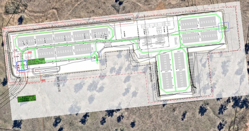
The facility can be generally divided into three parts being the O & M Buildings, the Substation Yard and the BESS Yards. These are made up of:
◼ Battery storage arrays: There will be 16 arrays of Tesla 2 XL Megapack, each one with 28 Megapacks 2 XL for a total of 448 Tesla Megapacks 2 XL that will be outdoors (i.e., not within an enclosure where a person can access).
The BESS Tesla Megapack 2XL consists of a modular design with battery module bays, a thermal cabinet, a customer interface bay, a thermal roof, an IP66 enclosure (Appendix G) and fire safety measures.
Figure 5 BESS array layout and access roads.
Orana
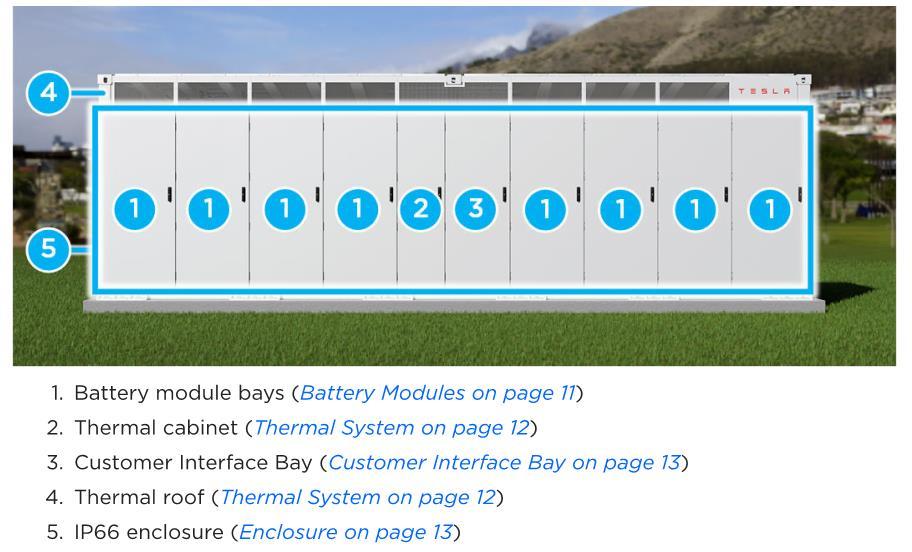

◼ Battery module bays. There are 8 module bays for each Megapack 2 XL, which are populated with lithium phosphate (LFP) cells (see figure above).
◼ Customer interface bay (CIB). It includes all the required connections for the initial installation, and then it is the main area for servicing and operation (see figure below). Operators must open the door to access and will remain outside the Megapack 2XL.
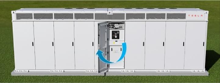
The Tesla Megapack 2XL is provided with multiple safety measures such as the following [13]:
◼ Battery Management system (BMS)
◼ Thermal management system (TMS)
Figure 6: Megapack overview.
Figure 7: Accessing the Megapack 2XL.
Orana Battery Energy Storage System (BESS)
◼ Overpressure vents/Explosion control system
◼ Site Controller and Monitoring
◼ Electrical Fault protection devices.
◼ Remote shutdown provisions.

◼ MV/SUT (Medium Voltage/Step-up) transformers [18] [19]. There will be 112 SUTs with the following characteristics:
◼ The Step-up transformers’ design is based on AS 60076 and IEC 60076.14 for High Temperature of Oil type KNAN (Natural Ester filled Cargill FR3) with an oil volume of 3,905L
◼ Its bund measures approximately 4.6 x 3.6 m. It is a self-bunded transformer that includes splash guards for AS1940 compliance
◼ Provided with enhanced protection.
◼ 330 kV HV Substation. There will be 2 transformers (330/33kV transformers) with the following characteristics:
◼ They will use mineral oil with oil volume of 71,000 litres (71.0 m3).
◼ Their bunds’ dimensions will be approximately 19m x 13m, and it has the capacity to hold 120% of the oil volume to account for water and overflow.
◼ The transformers will have 2 fire walls between them as per AS2067.
◼ 1 O&M building (Appendix B) It is a single storey building:
◼ Contains 2 offices, a kitchen and toilet facilities.
◼ It is a Class 5 building as per the NCC with type C construction.
◼ Colorbond cladding/roofing and internal walls made of Stratclad S-Lock (i.e., non-combustible metal sheet) [18] [19]
◼ It has a total area of 85m2 approximately.
◼ 1 Control building (Appendix B). It is a single storey building which contain electrical boards:
◼ It is a Class 8 building as per the NCC with type C construction.
◼ Colorbond cladding (i.e., non-combustible metal sheet) [18] [19].
◼ It has a total area of 68m2 approximately.
◼ Switch gears and RMUs. There will be two 33kv switchgear buildings and 16 RMUs spread among the arrays of BESS units:
◼ Those switchgear buildings are classified as a Class 8 building under the NCC and have an area of approximately 140m2 each and area. The RMUs are small switchgears that provide a continuous power supply and are specialized electric boards which are managed from outside as an outdoor electric board (i.e., they are not rooms or buildings like).
◼ They contain SF6 gas.
Orana
Battery Energy Storage System (BESS)
◼ Storage shed:
◼ It is a Class 7b building as per the NCC with type C construction.
◼ Colorbond cladding (i.e., non-combustible metal sheet).
◼ It has a total area of 225m2 approximately.
The facility also has 10m wide firebreaks and 5.0m wide road access as shown in Appendix A.
The site will also be provided with extinguish systems:

◼ Portable fire extinguishers as per AS 2444 and security cameras (Section 10) No other fire-fighting measures such as fire hydrants are provided given the small size of the buildings.
◼ A fire hydrant system throughout the facility in accordance with AS2067.1-2019, which will be fed from a water storage of 288kl.
There are multiple access entrances. The primary access is located at the South-West of the site via the access road; and there are two other access points which should be used as secondary means if the Primary access is compromised, these secondary accesses are located at the South and the East of the Site.
The site will be open from 0700 – 1700 hours, and there will be an out of business hours on Akaysha Energy on call roster.

Dominant Occupant Characteristics
The average number of occupants on site will be usually 5 staff, where 4 staff are Tesla crew and 1 Site Manager.
Based on the use of the subject site, the occupant characteristics and attributes have been identified as part of the performance process and are summarised in Table 3 below.
Table 3 - Dominant Occupant Attributes.
Attributes
Staff
State of awareness
Familiarity with the building
Mental and physical aspects
Description
Generally alert, awake and aware of their surroundings. It is considered that being a place of work the staff members will not be under the influence of drugs or alcohol.
Due to being members of staff it is expected that they will generally be aware of the building configuration and exit routes.
Staff are generally not expected to have a mental or physical impairment.
Emergency training It is not expected that the members of staff are trained in the operations of the firefighting systems. However, it is expected that the staff members will be aware of the actions required during an event requiring an evacuation, use of portable fire extinguishers and summoning the fire Brigade
Orana Battery Energy Storage System (BESS)

Location and adjacent allotments

The Orana BESS is located in the Dubbo Region in New South Wales (NSW) 2820 (Figure 8). The subject BESS is wholly located within the allotment where the Wellington Substation is also located (Figure 9), and the allotment is bounded by Goolma Road to the north and by Twelve Mile Road to the east, south and east sides (Figure 9).
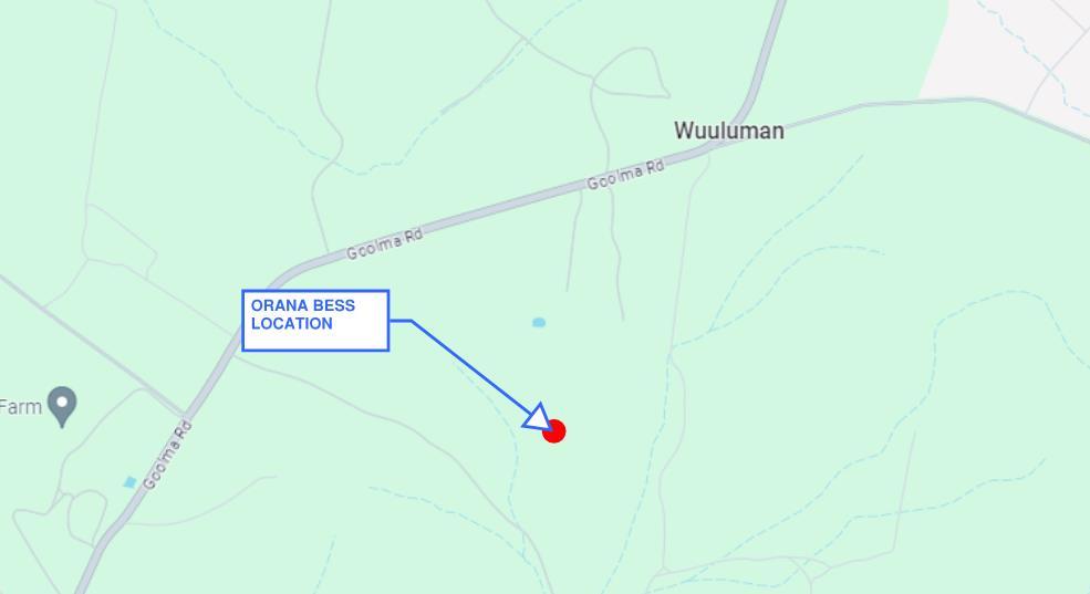
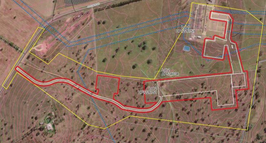
within allotment Location (red line limits the subject allotment).
Figure 8: Site Location.
Figure 9: BESS
Orana Battery Energy Storage System (BESS)

The adjoining allotments around the subject site are used for agricultural production, and the closest residential areas according to the NSW Planning portal [4] are 2 large Residential Lots located to the west and north-east sides of the subject BESS allotment (Figure 10) at more than 0.9km and more than 1km respectively
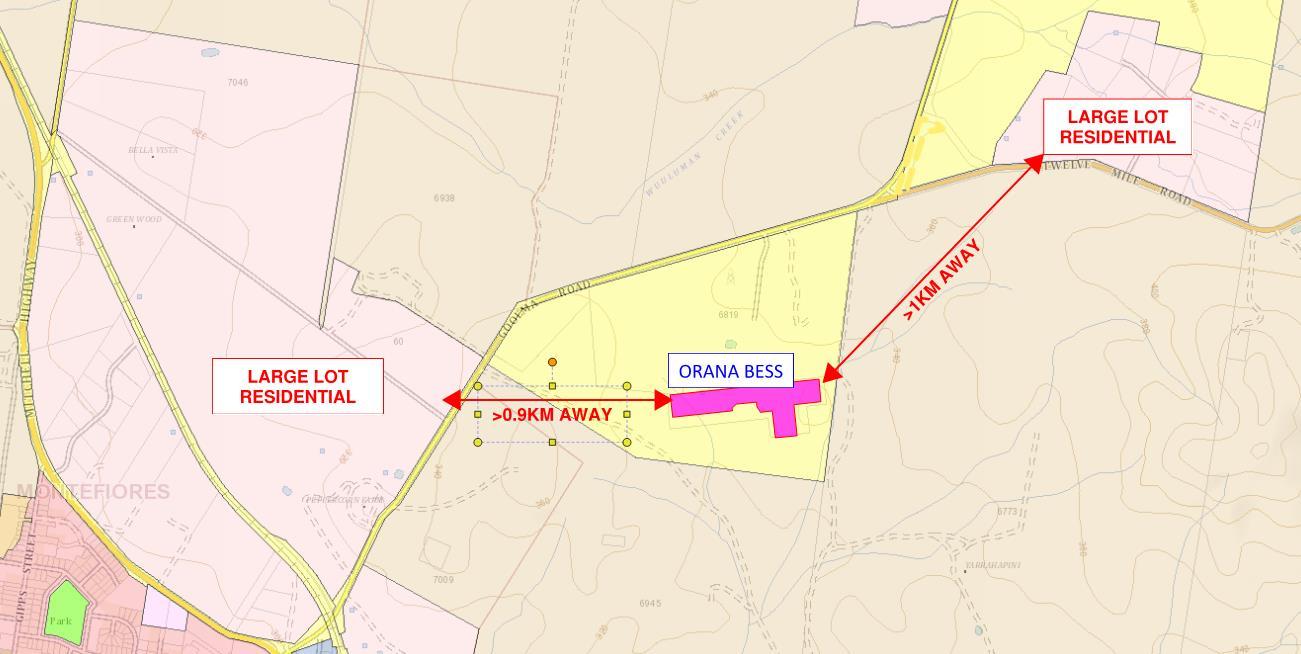

Land Zones
In accordance with the NSW Planning portal, the Orana BESS site and its allotment is classified as SP2-Infrastructure for electricity supply industry, and all the surrounding allotments are classified as RU1-Primary production, where land is primarily intended to promote agricultural production and environmental protection (Figure 11 and Figure 12).
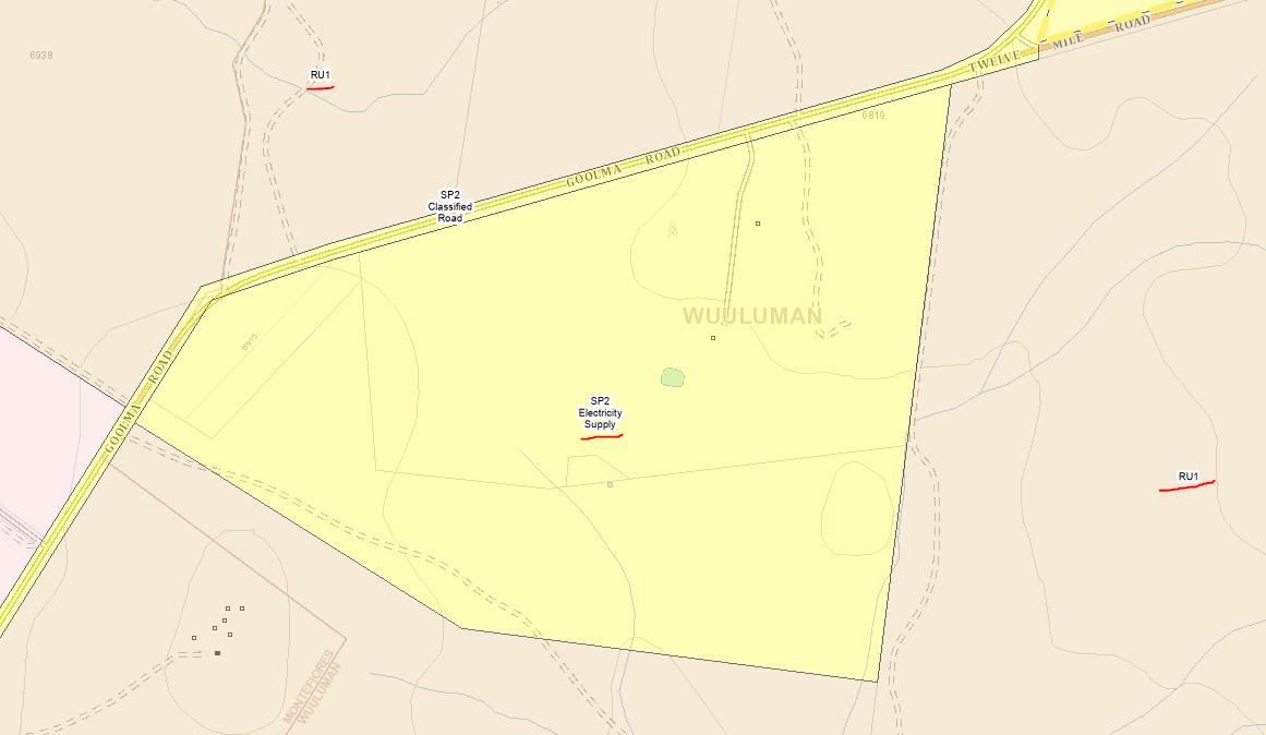
Figure 10: Closest habitable areas.
Figure 11: Land Zoning.

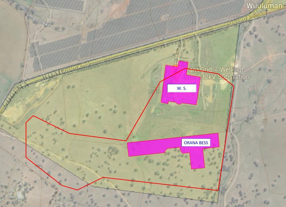
12: Site and BESS and surroundings Zoning.
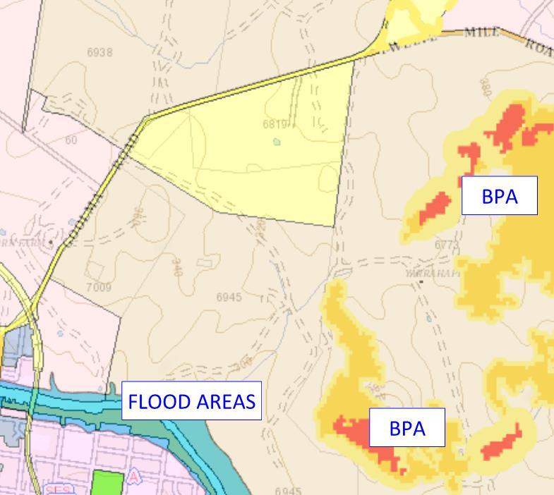
The subject allotment and BESS are out of the flood and BPA (Bush Fire Prone) areas in accordance with the NSW Planning portal (Figure 13) [4]. Therefore, no BAL (bushfire assessment level) assessment is required to be addressed in this document in accordance with the AS3959-2018.
Figure
Figure 13: Site Zoning (Bushfire and flood prone areas)
Orana Battery Energy Storage System (BESS)

Mudgee Airport AWS weather conditions

The closest weather station to Orana BESS is the Mudgee Airport AWS. In accordance with the available data at the Bureau of Meteorology, the average weather conditions are the following (Figure 14, Figure 15) [20]:
◼ The average temperature is 22.8oC and the highest mean maximum temperature is 30.9oC for the month of January.
◼ The mean relative humidity is 58%, between 44% and 72%.
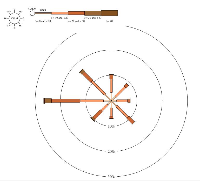
◼ Wind statistics (Figure 14):
◼ Wind is calm 1% of the time.
◼ The strongest wind comes from the east with a speed of more than 40 km/hr (11.1m/s), approximately 3% of the time.
◼ Average speed of the wind is between 18.8km/hr (5.0 m/s).
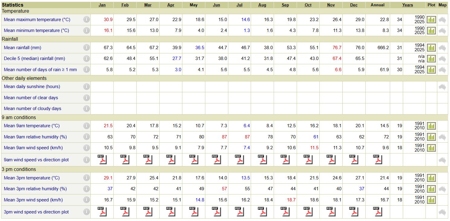
Figure 14: Mudgee Airport AWS weather statistics.

5.2 FIRE BRIGADE

Fire Brigade Objectives
The overall philosophy of the Fire Brigade objectives throughout Australia is to protect life, property and the environment from fire as noted in the FBIM [17]
Firefighters must be given reasonable time to enter buildings to conduct occupant search and rescue activities and to carry out internal firefighting before exceeding conditions that are likely to threaten fire fighter safety and prior to building collapse
Under reasonable circumstances, structures must not collapse onto adjoining property, and fire spread must be prevented. Also, fire spread within a building must be limited.
The Fire Brigade also has functions with regard to property protection and considerations regarding occupational health and safety for its employees. These issues are outside the building regulatory framework and NCC.
Figure 15: Wind Rose for Wellington research centre station.
Battery Energy Storage System (BESS)

Fire Brigade Stations

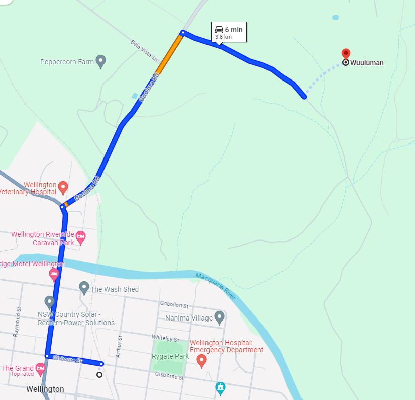
The closest fire brigade stations are the Fire & Rescue NSW Wellington Fire Station and the NSW Rural Service, which are located at 3.8km away (Figure 16) to the south of the subject site.

Fire Brigade Access
The access roads to Orana BESS will be located at multiple sides of the site, so it can be accessed from Goolma Road (see Appendix A). There will be a total of 3 entrances/exists to the BESS. The primary access is located at the SouthWest of the site via the access road; and there are two other access points which should be used as secondary means if the Primary access is compromised, these secondary accesses are located at the South and the East of the Site.
The access roads and roads around the BESS array areas are not less than 5.0m wide.
Orana
Figure 16: Wellington Fire Stations.

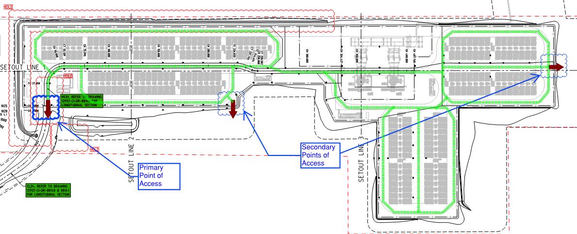
The battery arrays (see Appendix A) are separated by no less than 5.0m wide roads for fire brigade truck and maintenance purposes, and the roads extend around and within the facility. The fire truck will run within the fence that encloses the facility to reach all equipment.
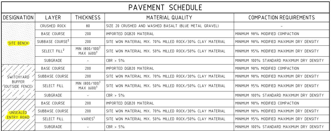
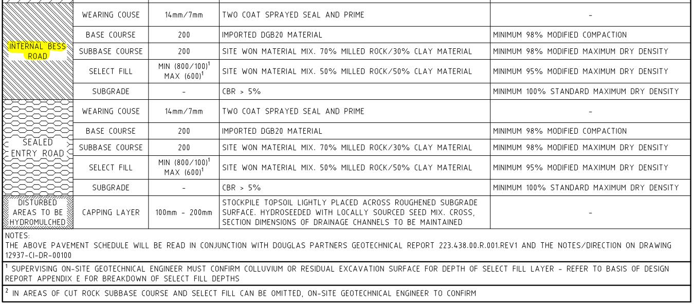
The roads provided to the development vary according to the location of the road. The road types and construction that will serve the BESS development are shown in Appendix C
As per the Appendix C and Pavement Schedule, the main roads that will serve the fire brigade intervention procedures are listed below, and their construction details are described in Table 4
◼ Site bench. Around the BESS arrays.
◼ Unsealed entry road. Roads from Goolma Road to site.
◼ Internal BESS Road. Main roads within the BESS site.
Figure 17: Access roads to BESS.


General Fire Safety Strategy
All equipment will be Scada Alarmed and will notify automatically the operators, who will proceed according to the Emergency plan and the protocols provided by the equipment suppliers. Any fire associated with the battery is confirmed via telemetry and the 24/7 operations center that will call out the brigade.
The detection systems are described in Section 9, where fire and multiple fault detectors are described for all the equipment and ancillary buildings.
In the worst case scenarios assessed in the study where any equipment or infrastructure is on fire, the total burn out can be allowed without the need for FRNWS intervention given that fire spread is not expected to occur between equipment/infrastructure (Sections 7.2). If a building is on fire, the Fire Brigade can proceed with the standard fire brigade intervention procedures as they judge convenient given the fire protection systems provided and the input from the staff.
Battery Energy Storage System (BESS) Page 31 of 112
Orana
Table 4 – Pavement Schedule.

As part of the fire protection systems, portable fire extinguishers and a fire hydrant system are provided throughout. Where any infrastructure or equipment is on fire, the fire brigade can use the fire hydrant system to cool adjoining areas/vegetation/infrastructure if required while the main fire extinguish itself (i.e., not to attempt to extinguish the main fire).
Although fire spread is not expected, the fire brigade will have available a water storage of 288kl for bushfire events or manage sites’ fires as per above
It is expected that the responding Fire Brigade will respond to site after notification of an event by an emergency call from the staff on site, the staff monitoring the site remotely or a member of the public when any of them visualise a fire. When the fire brigade intervenes, they are expected to help control a safe perimeter around the fire and allow equipment on fire to self-extinguish.
Firefighters should wear self-contained breathing apparatuses (SCBAs) and structural firefighting gear as per the requirements of the Tesla Response Guide [2]
All gates to secondary access are provided with 003-key padlocks to facilitate the access of the Fire Brigade via any entrance available to the site, and the main entry will be handled via intercom. Staff will always assist the fire brigade when they arrive to the site.
The attending personnel and vehicles will be equipped to commence the firefighting activities including investigations, set up and firefighting.
Also, as part of the fire brigade expertise, the fire brigade can assist in the management of fire of any of the ancillary buildings, such as the O&M Building, storage sheds and Switch gear buildings. This will be described in the Emergency Management Plan [5]
Before the worst-case scenario above occurs to a Megapack 2XL or transformer, the risk of a potential fire may be detected by the fire safety measures (refer to Section 9). When any of those sensors is triggered, the signal of the abnormal condition is detected by the safety systems and sent to the 24/7 remote monitoring center via the tesla site controller for appropriate action [2].

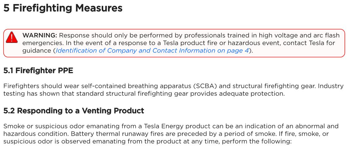
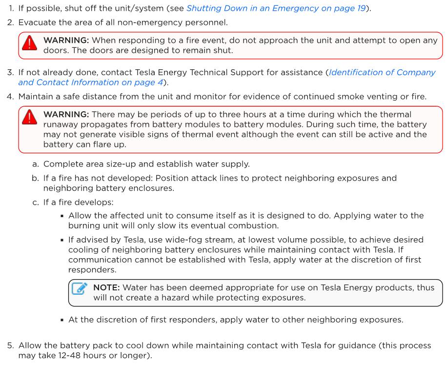
Figure 18: Firefighting measures for Megapack 2XL [2].
Detailed contacts and further emergency responses will be listed in the Emergency Management Plan of the site [5], and it will also consider the input from the equipment suppliers where provided


FIRE HAZARDS IDENTIFIED
The subject BESS will comprise a number of equipment components with associated hazards The main hazards associated to the subject facility are the following:
◼ Thermal runaway events in Megapacks 2XL and hence fire spread to adjoining equipment/facilities.
◼ Fire from substations and hence fire spread to adjoining equipment/facilities.
◼ Fire from transformers and hence fire spread to adjoining equipment/facilities.
◼ Fire from GIS or other facilities and hence fire spread to adjoining equipment/facilities.
◼ Bushfire hazard from adjoining allotments.
◼ Release of contaminant gasses (i.e., pollution) and toxic gasses (i.e., HF, HCL, and HCN) from the Megapacks 2XL.
◼ Leakage of the transformers’ oil and contaminated water runoff.
◼ Electrocution and EMF Hazards.
◼ Flammable liquids or gasses.
The following section will explain past events, causes and findings regarding the above risks, and the fire safety measures are described in Sections 8, 9 and 10
6.1 THERMAL RUNAWAY EVENTS IN MEGAPACKS 2XL AND HENCE FIRE SPREAD TO ADJOINING EQUIPMENT/FACILITIES.
The subject site will comprise Tesla Megapack 2XL energy storage units. There will be 16 arrays of Tesla 2 XL Megapack, each one with 28 Megapacks 2 XL for a total of 448 Tesla Megapacks 2 XL.
One of the main hazards associated with the use of lithium batteries for energy storage is overheating and thermal runaway resulting in a fire. Cell thermal runaway refers to rapid self-heating of a cell derived from the exothermic chemical reaction of the highly oxidizing positive electrode and the highly reducing negative electrode; it can occur with batteries of almost any chemistry.
Lithium-ion batteries contain highly energetic materials and combustible materials (i.e., electrode, separator, electrolyte and organic solvents). If they are subject to overcharging, short circuit, extrusion, collision and exposed in fire, this can trigger thermal runaway and lead to a fire and explosion.
The combustion process of batteries could be summarized into the following stages: heating to ignition, violent ejecting or explosion, stable burning, and weakening and extinguishment. Both the state of charge and incident heat flux have significant impact on the combustion behaviour of the battery. The battery with high charge presents a fierce combustion process and higher surface temperature than the others, especially when imposed with a high external heat flux.
In order to obtain an understanding of the hazards associated with BESS facilities a summary of past fires is presented below including the Moorabool Fire (i.e., Victorian Big Battery (VBB) fire).
Orana Battery Energy Storage System (BESS)

Likelihood

In the Article “Burning concern: Energy storage industry battles battery fires”, in the S&P Global market Intelligence website, 24 May 2019 it was reported by Ken Boyce, a principal engineer at product safety certification, testing and advisory firm UL LLC that: "In general, it's a very safe technology. Lithium-ion battery cells fail at a rate of only around one in every 12 million”. This is the rate of 8x 10⁻⁸ per year.
Since 2011, Electric Power Research Institute (EPRI) has recorded 81-88 incidents of BESS failures worldwide, where:
◼ 5.78 average failures per year per 530MWh.
◼ 0.63 failures per year due to battery cells/modules per each 530MWh.
◼ 0.01589% of MWh will have a failure incident per year (i.e., 1.59 x 10⁻⁴ failures per year per MWh).
Below are described some of the main events that have contributed to the design of the latest fire safety measures to the BESS technology, enhancements to prevent catastrophic events.

Victorian Big Battery fire
The Energy Safe Victoria (ESV) “Statement of Technical Findings - Fire at the Victorian Big Battery” provides a summary of the key findings into the fire (refer to Appendix E).
On 30 July 2021, the Victorian Big Battery (VBB) experienced a fire that involved two Battery units during commissioning.
The root cause of the fire was found to be a leak within the cooling system that caused a short circuit that led to a fire in an electronic component. This resulted in heating that led to a thermal runaway and fire in an adjacent battery compartment within one unit, which spread to an adjacent second unit.
The contributing factors into the fire were reported to be:
◼ The supervisory control and data acquisition (SCADA) system took 24 hours to ‘map’ to the control system and provide full data functionality and oversight to operators. The unit that caught fire had been in service for 13 hours before being switched into an off-line mode when it was no longer required as part of the commissioning process. This prevented the receipt of alarms at the control facility.
◼ A key lock was operated correctly to switch the unit to off-line service mode (which was no longer required for ongoing commissioning), but this caused:
◼ Telemetry systems for monitoring the condition of the (now out of service) unit to shut down and so remove visibility of the developing event.
◼ The battery cooling system to shut down.
◼ The battery protection system to shut down, including the high voltage controller (HVC) that could have operated a pyrotechnic fuse to disconnect the faulty battery unit.
The lessons learnt from the fire were reported to be:
◼ Each cooling system is to be fully functional, and pressure tested when installed on site and before it is put into service.
◼ Each cooling system in its entirety is to be physically inspected for leaks after it has been functionally, and pressure tested on site.
Orana Battery Energy Storage System (BESS)

◼ The SCADA system has been modified such that it now ‘maps’ in one hour and this is to be verified before power flow is enabled to ensure real-time data is available to operators.
◼ A new ‘battery module isolation loss’ alarm has been added to the firmware; this modification also automatically removes the battery module from service until the alarm is investigated.
◼ Changes have been made to the procedure for the usage of the key lock during commissioning and operation to ensure the telemetry system is operational.
◼ The high voltage controller (HVC) that operates the pyrotechnic fuse remains in service when the key lock is isolated.
The over pressure vents in the roof of the units involved in the VBB fire were seen as the main fire propagation method and a weakness in the fire spread prevention. (The effect of vents on possible fire spread scenarios versus the consequence of an overpressure event if they were not installed will be assessed as part of the detailed assessment of the final unit design).
The wind conditions at the time of the VBB fire were 37 – 56km/hr which based on the wind data for Orana BESS location would only occur approximately 3% of the time, i.e., a probability of 0.03.
It was recommended in the report that one of the hardware mitigation measures is the installation of newly designed, thermally insulated steel vent shields within the thermal roof of all units.
The fire did not spread beyond the two units and no members of the public or emergency services were indicated to have suffered significant injuries.

Incident Report – Bouldercombe BESS.
The Bouldercombe BESS is a 50MW and 100 MWh battery comprised of 40 individual Megapack 2 (MP) energy storage systems (See Figure 19).
The report provided by Tesla Energy Products stated the following:
“On Tuesday September 26, 2023, a single Megapack caught fire and was left to fully consume itself over approximately 48hrs without the need for water/fire suppressant to be applied by First Responders as per Tesla’s Industrial Lithium-Ion Battery Emergency Response Guide. No workers were at risk of harm and the battery failed in a safe manner, as the system is designed to do in the event of a fire”.
“A second Megapack (MP2TG122340001W76), installed directly behind the initiator Megapack, was found to have signs of secondary heat effects and was removed. The total impact to the site was 2 out of the 40 MPs on site”.
The incident demonstrated that given a fire to a Megapack, fire will be limited to the affected Megapack only and fire will not spread to adjoining Megapacks, transformer or structures, however heat may damage some of the components of the Megapack at the back.
The Bouldercombe BESS had a normal operation despite of the event due to the provision of safety and redundancy systems, the loss of the 2 megapacks did not affect the normal operation of the BESS development.
In regard to the root cause of the fire, the analysis determined a load-side AC fault occurred leading to fault cascading within the Megapack. Further studies and tests are being performed in order to assess further electrical faults of the Megapack.

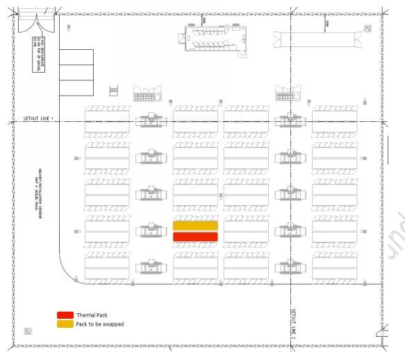
Figure 19: Bouldercombe BESS Site Layout and Megapacks involved in the event.

Elkhorn BESS Fire of September 20, 2022. Public Report of Technical findings.
The Elkhorn BESS is located at the Moss Landing Electric Substation in Monterey County, California, and it has the capacity to store and dispatch up to 730 megawatt hours (MWh) of energy.
The facility is provided with the first version of the Megapack (also referred to as the Megapack 1 to distinguish it from second-generation of Tesla BESS called the Megapack 2).
In September 2022, a fire occurred to a single Megapack as shown in the picture below (Figure 20). In summary, “The fire proceeded in accordance with its design and consumed itself. It burned as a flaming fire for about 6 hours, and then generated visible smoke and off-gas for another 12 hours. As per the instructions in Tesla’s Lithium-Ion Battery Emergency Response Guide (ERG), which were incorporated into the PG&E Pre-Fire Plan, the Megapack was allowed to burn and consume itself while being monitored by first responders at a safe distance”.

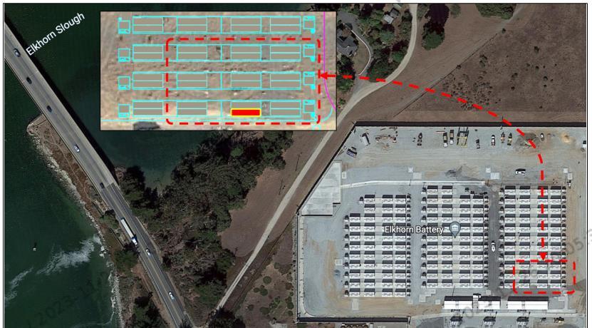
The above demonstrated that where a Megapack is on fire, fire is not expected to spread to adjacent Megapacks or adjoining structures, and fire will be limited to the affected Megapack.
The Root Cause Analysis of the incident identified the following causes:
◼ Significant water ingress, which allowed electrical shorts to initiate the thermal runaway of the battery cells.
◼ There were additional confounding factors that influenced the fire event during the Pre-Incident time frame, that is, the two days prior to the fire event. These included: (1) Auto-Safe Discharge; (2) Tesla Monitoring Alarm; and (3) Playbook Guidance.
Given the Root Cause Analysis above, the enclosure, manuals and software for the Megapack 2 and Megapack 2XL were updated accordingly to mitigate the risk of ignition of the Megapack.

Thermal Runaway / Fire within a battery
One of the reasons lithium-ion cell thermal runaway reactions can be very energetic is these cells have very highenergy densities compared to other cell chemistries. The other reason that lithium-ion cell thermal runaway reactions can be very energetic is because these cells contain flammable electrolyte, and thus, not only do they store electrical energy in the form of chemical potential energy, but they also store appreciable chemical energy (especially compared to cells with water-based electrolytes) in the form of combustible materials.
Self-heating of lithium-ion graphitic anodes in the presence of electrolyte initiates at temperatures in the 70 to 90°C range. Thus, if a cell is brought to this initiating temperature in an adiabatic environment, it will eventually self-heat to the point thermal runaway initiates. For a typical 100% charged cell brought to its self-heating temperature, thermal runaway will occur after approximately two days if the cell is well-insulated. Should initial temperature be higher, time to thermal runaway will be shorter. For example, if a typical lithium-ion cell is placed into an oven at more than 150°C (300°F), such that separator melting occurs, additional heating due to shorting between electrodes will occur and cell thermal runaway will initiate within minutes. However, if heat is allowed to escape, time to thermal runaway may be longer, or the cell may never achieve thermal runaway.
Figure 20: Overview of Elkhorn BESS and Megapack on fire.
Orana Battery Energy Storage System (BESS)

Measurement of cell case temperatures during thermal runaway experiments have been performed by laboratories such as UL. For fully charged cells, these temperatures can reach in excess of 600°C case temperatures. The temperature rise is driven by reactions of the electrodes with electrolyte and release of stored energy. Some cathode materials will decompose and may change their crystalline structure which may result in the release of small quantities of oxygen that can participate in reactions internal to the cell (e.g., oxidation of the aluminium current collector).
This fact has led to a misconception that lithium-ion cells burn vigorously because they “produce their own oxygen.” This idea is incorrect. No significant amount of oxygen is found in cell vent gases.1 Any internal production of oxygen will affect cell internal reactivity, cell internal temperature, and cell case temperature, but plays no measurable role in the flammability of vent gases.

Research and Testing of Lithium-Ion Batteries and BESS
Tesla Megapack 2XL energy storage units have been tested to the three levels of the UL9640A (i.e., cell, module and unit level). Reports are listed below:
◼ Fire Protection Engineering Analysis to Tesla BESS units. Fisher Engineering. Project reference 22035, dated 23/01/2023 [13]
◼ Tesla Megapack 2 and 2 XL – Destructive Fire Test and Fire Modelling Report. Fire & Risk Alliance. Revision 0 dated 15/04/2024 [11]
The reports above demonstrated that fire spread between Megapacks 2 and 2XL is not expected due to the provision of the Overpressure vents/Explosion control system and multiple electrical safety measures. Further results are discussed in Section 7.2

FPRF/Exponent Hazard Assessment of Lithium-Ion Battery ESS
Exponent Inc. and the NFPA’s Fire Protection Research Foundation conducted a full-scale fire test of a Tesla Powerpack – 100kWh lithium-ion BESS at 100% SOC2. Two tests were conducted, one with an external ignition source of 400 kW and another with an internal ignition by heater cartridges. The internal test set individual cells into thermal runaway to simulate an internal failure, and the external test led the internal cells into failure through heat exposure.
The results of the external ignition test determined the following:
◼ A fire in the Powerpack resulted in internal temperatures exceeding 1,093°C, and external temperatures reached 232°C.
◼ Flames were observed coming out of the exhaust vent and out of the BESS front door.
◼ Flames several feet high were observed from the exhaust vent of the Powerpack.
◼ Heat flux of approximately 25kW/m2 measured 1.8m from front of BESS.
1 Lithium-Ion Batteries Hazard and Use Assessment, Final Report, Celina Mikolajczak, PE, Michael Kahn, PhD, Kevin White, PhD ,Richard Thomas Long, PE, Exponent Failure Analysis Associates, Inc., July 2011 National Fire Protection Association, Fire Protection Research Foundation.
2 Blum, A. F., & Long, Jr., R. T. (2016). Hazard Assessment of Lithium-Ion Battery Energy Storage Systems. Quincy: National Fire Protection Association
Orana Battery Energy Storage System (BESS)
◼ All batteries and electronics of the BESS were damaged.
The internal ignition test gave the following results:
◼ A fire in the Powerpack resulted in internal temperatures exceeding 1,093°C.
◼ Temperatures at pods below the initiator pod showed temperature ranges between 26 and 82°C.
◼ External temperatures reached 21°C.
◼ Initiator pod was damaged, but other cells were not damaged.


US FAA-Style Flammability Assessment of Lithium-Ion Cells and Battery Packs in Aircraft Cargo Holds
The exponent conducted flame attack tests on single prismatic batteries and prismatic battery packs inside a cargo hold 3. The result of this testing provides insight into battery behaviour under fire conditions as well as temperature profiles of the fire events.
Key findings from these small-scale tests include the following:
◼ Frequent battery case rupture events were observed in the prismatic battery pack testing.
◼ Direct flame impingement on small, unpackaged quantities of prismatic battery packs can lead to thermal runaway of individual cells and venting of gases. The vent gases are generally ignited by the pre-existing flame, increasing the total heat flux produced by the fire.
◼ Testing of 4 cell li-ion battery packs produced ceiling temperatures between 400°C and 600°C.

FAA Energetics of Lithium-Ion Battery Failure
The Federal Aviation Administration (FAA) has worked to quantify the hazard of lithium-ion batteries under a fire event since a fleet of the Boeing 787 Dreamliner were grounded as a result of hazards associated with LIB fires. In addition to the fire events, large numbers of lithium-ion batteries are being shipped as cargo on aircraft. Although the failure of a single cell is a low probability event (1/1,000,000), the large quantity of batteries on aircraft and the severe impact of an event on the survivability of the aircraft make the risk a safety concern to the passengers.4
To analyse the hazard of lithium-ion batteries undergoing a thermal runaway event in an aircraft, a pallet load of 18,650 cylindrical batteries were forced into thermal runaway within a cargo hold of an aircraft. This test showed that all of the batteries became involved in the fire. This testing provided data regarding lithium-ion battery fires and heat release rate curves providing insight into the growth function of a fire involving multiple packs of lithium-ion batteries. This study is applicable to quantifying a fire event in a BESS due to the number of batteries in a confined compartment.
The results indicated the heat release rate per battery cell was approximately 5kW.
3 Mikolajczak, C. (2005). US FAA-Style Flammability Assessment of Lithium-Ion Cells and Battery Packs in Aircraft Cargo Holds. Exponent. Menlo Park: Exponent.
4 ] Lyon, R. E., Walters, R. N., Crowley, S., & Quintiere, J. G. (2015). Fire Hazards of Lithium-Ion Batteries. Federal Aviation Administration. Atlantic City: Federal Aviation Administration.

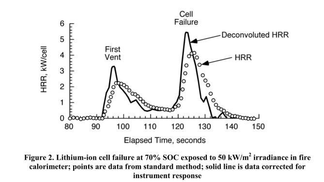
21: Results of a single group of batteries.
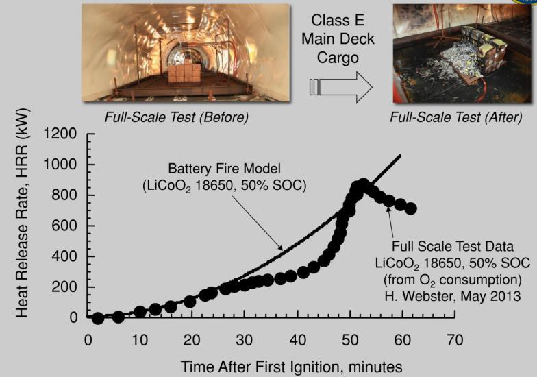
Figure 22: Results of full-scale tests on 18650 batteries.
The peak heat release rate is approximately 1MW.

DNV GL Considerations for ESS Fire Safety
DNV GL and Rescue Methods were contracted by Con-Edison Power and the New York State Energy Research and Development Authority (NYSERDA) to address a series of frequently asked questions regarding BESS Fire Safety5. This work included testing of lithium-ion batteries of various chemistries as individual cells and battery modules. The individual cells were exposed to a 4-kW radiant heat source until they vented inside DNV GL’s Large Battery Destructive Testing Chamber. For the module testing, modules between 7.5 and 55 kWh were ignited inside a partially closed metal container by direct flame impingement from a propane torch. The module testing provided data concerning the effect of oxygen, toxicity, and heat release rate of the fire.
5 DNV GL. (2017). Considerations for ESS Fire Safety. Dublin: DNV GL
Figure

A few key findings from this testing are discussed below:
◼ Batteries are more volatile at higher states of charge (SOC).
◼ Mass loss rate is proportional to SOC. Average mass loss rate: 18% mass loss over 41.7 min.
◼ If flames are visible and temperature is rising, the ESS is likely to have multiple batteries and/or modules involved in the fire. Rising temperatures within the ESS is an indication of increasing risk.
◼ The batteries themselves emit flammable gases.
◼ Recommended Ventilation Rate Correlation of 0.095 - 0.15 l/s/Wh.
◼ HRR produced variable results. The range was between 2.5 – 80 kW/kg, depending on volume of gases, duration of release, rate of ignition, and gaseous mixture.
◼ Partially burned systems can continuously emit flammable gases as long as the cells retain their heat – even if the fire has been extinguished.

Rate of Heat Release
The Rate of Heat Release for the battery units is dependent on the state of charge as well as the size of the batteries and the incident heat flux.
It was reported in “Fire behaviour of lithium-ion battery with different states of charge induced by high incident heat fluxes”, by Zhi Wang that the peak heat release rate of a battery unit is approximately 700kW/m2 to 1050kW/m2 and an average of approximately 150 – 200kW/m2 .
Note these are individual small batteries and not part of a BESS unit and the area is the surface area of the batteries. Based on the size of the units in the VBB fire as reported by the ESV investigation (7.5m x 1.6m x 2.5m) and assuming the front and the top of the unit are burning based on the location of the ventilation, the heat release rate is predicted to be 4.5MW to 6MW.
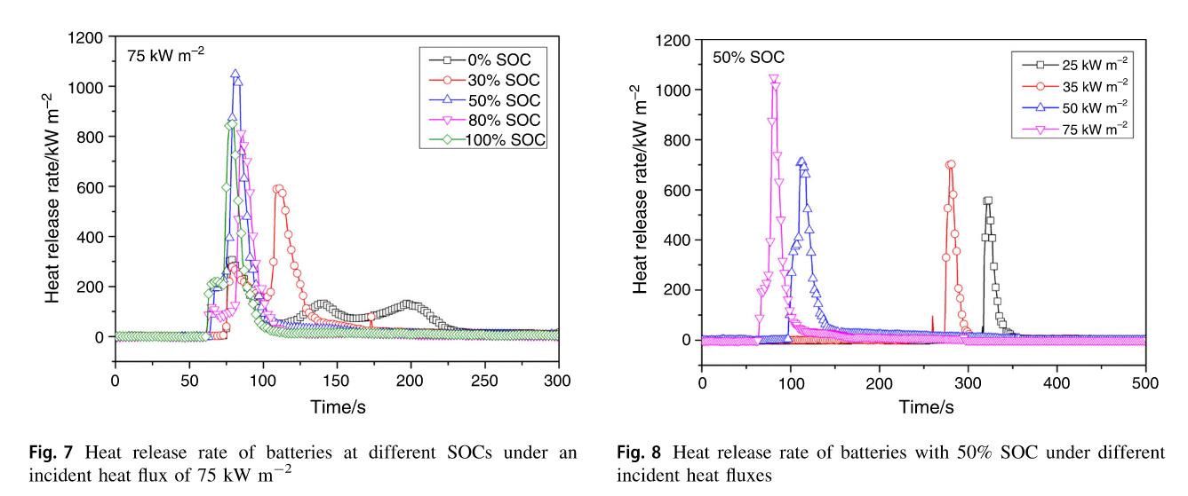
Figure 23: Tested heat release rates for Lithium-ion batteries.
Orana Battery Energy Storage System (BESS)

Based on the above review and an average of 200kW/m2, it is considered that each ESS Tesla Megapack 2 XL will have an average total heat release rate of approximately 7.0MW, considering that total dimensions are approximately 8.8m x 1.65m x 2.785m (i.e., superficial area of 6m2) [13]
6.2 FIRE FROM SUBSTATIONS
Orana BESS has a 330 kV HV Substation, composed by 2two 330/33kV transformers.
The combustible materials in distribution substations and equipment involved in substation fires may include the electrical wire or cable insulation, transformers (e.g., transformer fluids, especially oil), valves, outdoor or indoor oilinsulated equipment, oil-insulated cable, hydrogen-cooled synchronous condensers, PCB-insulated equipment and other items.
The Ministry of Economic Development (MED) provides annual statistics reports in New Zealand. In accordance with MED, from the substation’s fires in New Zealand between 1946 and 1995, 65% of these fires had the electrical wire or cable insulation as the object first ignited (Figure 24). Compared to the cable insulation, the probability of having transformer or transformer fluid as the object first ignited is much lower (20%).


The EEP (Electrical Engineering Portal) [21] indicates that fires in substation are not common, however consequences are catastrophic for the company and consumers. The EEP lists the types and origins of fires in substations between 1971 and 1994 in Figure 25
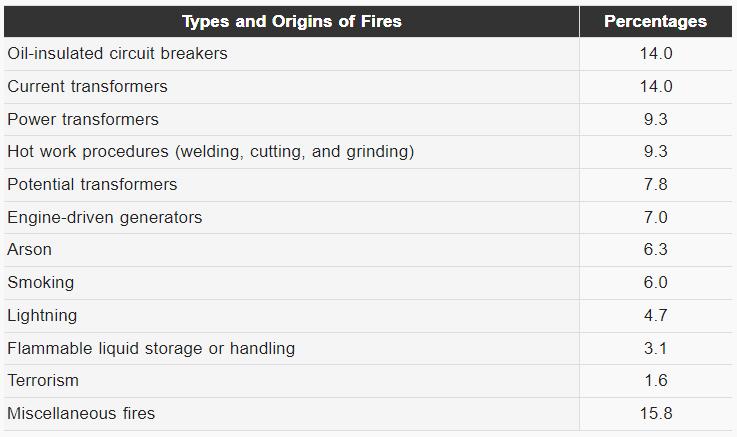
Figure 24: Substation fires distribution.
Figure 25 – Types and origins of Substations fires. [21]
Orana Battery Energy Storage System (BESS)

Also, CIGRE [22] has completed a survey of reliability and failures of in-service high voltage equipment, such as SF6 circuit breakers, disconnectors, earthing switches, instrument transformers and GIS. The survey gathered data from 90 utilities from 30 countries. The main findings were the following:
◼ The overall failure frequency for circuit breakers is 0.30 major failures per 100 circuit breaker years of service.
◼ For disconnectors and earthing switches the overall major failure frequency is determined to be 0.21 major failures per 100 circuit breaker years of service.
◼ Instrument transformers have an overall failure frequency of 0.053 major failures per 100 single phase instruments transformers years of service.
◼ In general, individual equipment installed in GIS appears to have lower failure frequencies than equipment in air insulated substations. The overall major failure frequency for GIS bays is about 0.37 major failures per 100 GIS circuit breaker bay years of service (a GIS circuit breaker bay includes one circuit breaker and all associated disconnectors, instrument transformers, interconnecting busducts and/or parts of busbars and associated terminals).
6.3 FIRE FROM TRANSFORMERS
Orana Bess will have the below transformers:
◼ MV/SUT (Medium Voltage/Step-up) transformers. There will be 112 SUTs.
◼ 330 kV HV Substation. Composed by 2two 330/33kV transformers
The following section details the likelihood of transformer fires from various sources:
◼ The last Australian CIGRE reliability report in 1995 came up with a failure rate for a failure causing a fire as 0.01%, i.e., 1x10⁻⁴/yr. This was for transformers above 60 kV.
◼ A more recent survey (not a formal survey) covering 1800 transformer tanks from 6 utilities over 7 years calculated a risk of causing a fire as 0.09%, i.e., 9 x 10⁻⁴/year (re CIGRE transformer Technology Conference 2008, presentation on Risk of Transformer fires by Arne Petersen).
◼ With regard to the Victorian transmission system for transformers 220 kV and above, there has only been one fire in 32 years giving a rate of 0.021%, 2.1x10⁻⁴/yr.
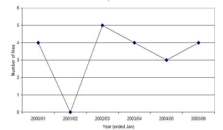
◼ The New Zealand Ministry of Commerce, now known as the Ministry of Economic Development (MED), is a government department responsible for the government ownership of public properties. The number of distribution substations and the population in New Zealand are provided in their annual statistics reports. The statistical data on the number of distribution substations in New Zealand was obtained from the MED between 1946 and 1995. Since the statistical data after 1995 was not available, the number of distribution substations between 1995 and 2006 is estimated based on the growth rate measured in the previous 50 years. The NZFS FIRS database during the 6 years period from January 2000 to January 2006 indicated 24 fire incidents, 20 fire incidents were related to distribution substations and 4 fire incidents are related to power or terminal substation. The 4 fires related to power or terminal substations were indicated to originate in switchgear areas or transformer vaults as shown in Figure 26
Therefore, the average rate of fire starts in a transformer is - 4 x 10⁻⁴/year.

6.4 FIRE FROM GAS INSULATED SWITCHGEAR (GIS) FIRE RESEARCH
The subject site has 2 buildings with 33kV Switchgears.
An incident in a GIS means that a high energy arcing fault (HEAF) may occur, and GIS are one of the equipment that are primarily susceptible to HEAF events.
The HEAF fault typically involves a short circuit from one, or more, of the bus bar connections to a ground or between phases of the power source through the surrounding medium (e.g., insulating fluid).
A HEAF may cause a fire within the GIS and inner GIS components and external structures may be affected. After the electric fault occurs, massive and localized pressure and temperature increases, metal vaporization, equipment failure, explosions, and an enduring fire may proceed.
When a HEAF occurs, pressure and temperature increase in the confined switchgear housing space. These events lead to expel molten metals and hot gases throughout the vicinity of the HEAF blast. “The high energy arc itself has been noted to reach temperatures of more than 20,000°C, instantly vaporizing bare metal and materials used to compartmentalize the interior electronics. Arc duration has been found to play a significant role in flame initiation. When an arc is able to burn without interruption, more hot gases and molten metals are created and ignition of the switchgear components becomes more likely”. [23]
In order for an arc to initiate in a switchgear, one or more of the followings situations are required [23]:
◼ Metal vaporization of electrodes.
◼ Poor (high resistance) connection to bus bars in switchgear equipment.
◼ Decayed and cracked electrical wiring.
◼ Failure of the insulation, or introduction of metal instruments or conductive debris.
◼ High voltages and currents along with normal equipment degradation.
◼ Debris and moisture.
Once a HEAF event occurs that leads to a fire, the vaporized metals from the GIS may lead to secondary HEAF events Research about fires in GIS have concluded the following (although further research is required):
Figure 26: Number of distribution substation fires in 2000/06 (Source NZFS FIRS)
Orana Battery Energy Storage System (BESS)

◼ “Routine maintenance and servicing along with improvements in component materials and grounding devices have not eliminated the concerns associated with HEAFs in switchgear” [23]
◼ “Arcs having less than 38 percent of the available fault current will self-extinguish” [23]. For greater currents the same result is not necessarily expected.
◼ Depending on the voltage, the higher the voltage the longer arcs occur, and radiative heat is produced. “Lee determined that fatal burns and major burns may occur at five and 10 feet away” [23]
◼ Instrumentation is a limitation in research of fire in GIS equipment.
◼ Fires, temperatures, and pressures are different for air and SF6, the 2 acceptable gasses for compliance.
◼ Fires are not often; however consequences are catastrophic.
◼ Fires are usually difficult to suppress.
6.5 FIRE FROM ANCILLARY AREAS
Minor areas in the facility are the O&M Building, a Control building and Storage sheds.
Those facilities do not comprise special hazards and are constructed as per the NCC DtS provisions, hence the risk of fire spread can be assessed as per the mythologies accepted by the NCC. Given the clearances shown in Appendix A, fire spread is not considered to occur, however further assessment is performed in Section 7.2 of this document.
6.6 BUSHFIRE HAZARD FROM ADJOINING ALLOTMENTS.
Given the location of the development, where the BESS area is out of the BPA (Bush Fire Prone) area, the risk of a bushfire is not required to be addressed (refer to section 5.1) in accordance with the AS3959-2018 and the Fire Safety Guideline [24]
6.7 RELEASE OF CONTAMINANT GASSES (I E., POLLUTION) AND TOXIC GASSES (I E., HF, HCL, AND HCN) FROM THE MEGAPACKS 2XL.
Given a fire to a BESS unit, HF (Hydrogen Fluoride), HCL (Hydrogen Chloride) and HCN (Hydrogen Cyanide) are the most common toxic gases released.
Tests as per UL9540A to all levels (i.e., cell, module, unit) to Megapacks 2XL measured the release of the above gasses. Those demonstrated that that HF was the only toxic gas released when the Unit was on fire. HCL (Hydrogen Chloride) and HCN (Hydrogen Cyanide) gases were not detected in any test [13]
Therefore, only HF can be expected to be a risk to human health.
Low concentrations of HF (e.g., 0.2-0.7 ppm) can cause irritation and mild symptoms, and higher concentrations (e.g., > 3 ppm) can cause severe burns, respiratory damage, and even death [25]
In accordance with the test results summarized by Fisher Engineering [13], “Internal unit level products of combustion testing demonstrated that HF was only detected at trace levels (0.10 and 0.12 ppm) in two sampling locations (approximately 20 feet upwind and 5 feet downwind from the MP2/2XL) when six cells within MP2/2XL cabinet were forced into thermal runaway. This trace quantity of HF was detected over the entire 2½ hour test duration (i.e., it was the cumulative quantity detected) and is well below the Immediately Dangerous to Life or Health (IDLH) value of 30 ppm for HF. The testing also found no traces of twenty-seven different metals, including lithium and mercury”.
Orana Battery Energy Storage System (BESS)

Other studies indicate that low concentrations of HF (e.g., 0.2-0.7 ppm) can cause irritation and mild symptoms, and higher concentrations (e.g., > 3 ppm) can cause severe burns, respiratory damage, and even death [25]
The above HF concentrations, which are more exigent than the thresholds described by Fisher Engineering, are still higher than what was measured during the test at 20 feet (6.0m).
Considering that the closest residential areas are located to more than 0.9km to the west and more than 1km to the north-east sides, it is expected that even lower concentrations than 0.12ppm or negligible concentrations can potentially reach the residential areas, and therefore those will not harm residents.
The Fisher Engineering [13] report indicates that 0.12ppm where measured when a battery module was induced to thermal runaway. In order to quantify the extent of toxicity of the HF around a Megapack 2XL BESS when 12 modules (half of the Megapack 2XL), a CFD model was performed.
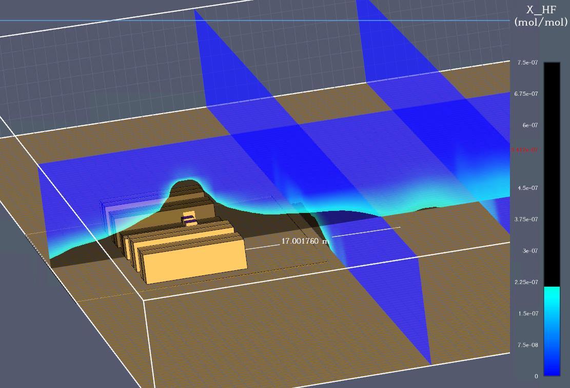
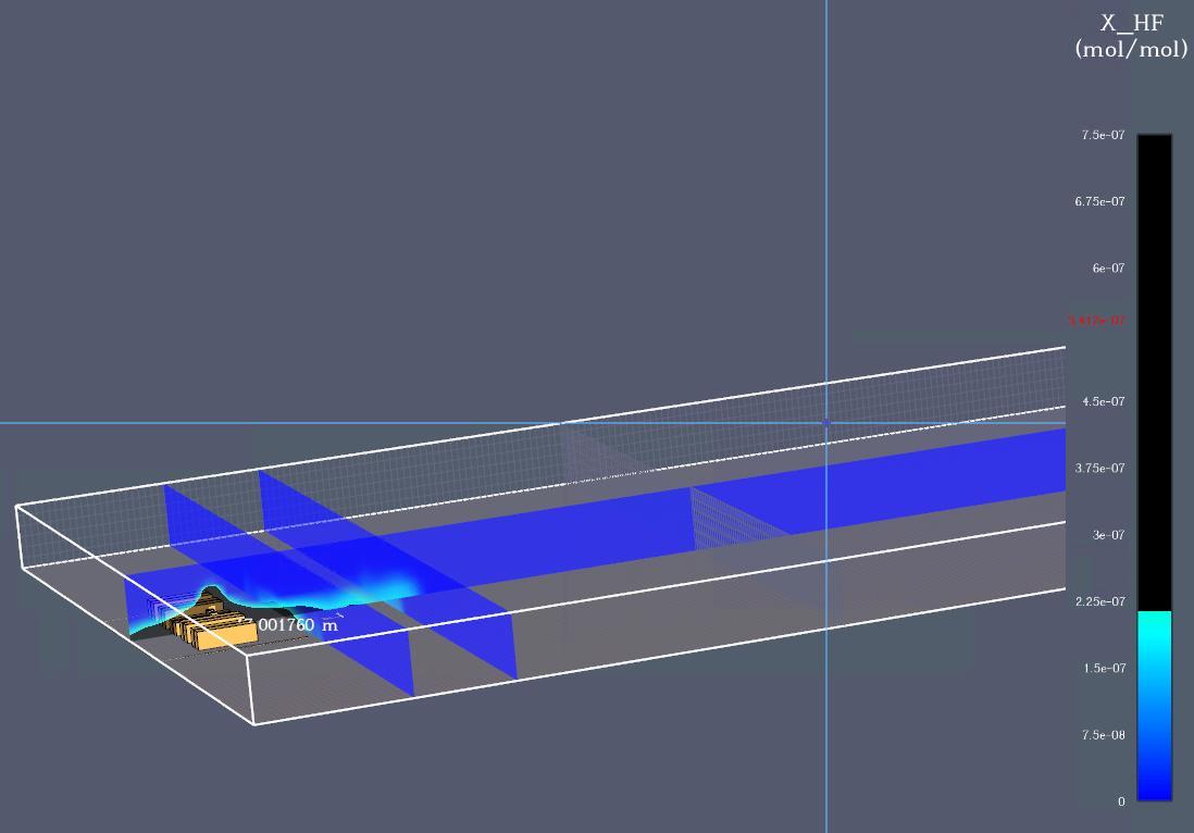
A conservative scenario to account for the concentration of HF from 12 modules assumed. Half of the Megapack 2XL (12 modules) will have thermal runaway conditions with flashover and ambient temperatures to show the behaviour of the HF, given that tests demonstrated that thermal runaway may occur also without flames, hence HF can be treated like a gas leak with ambient temperature.
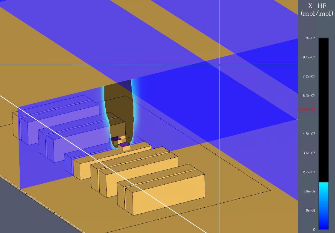
Figure 27: HF Concentration with fire (dark colour is more than 0.2ppm).

Orana Battery Energy Storage System (BESS)
Figure 28: HF Concentration without fire (dark colour is more than 0.2ppm).
Orana Battery Energy Storage System (BESS)

Where flashover conditions occur, Figure 27 shows that HF will vent to open air and its concentration around the BESS unit will not reach the critical values (i.e., less than 0.2ppm), whilst Figure 28 shows that a radius of 17m may be affected when 12 modules incur into thermal runaway. Residential allotments at more than 900m are not expected to be affected
If the HF flows when the wind is blowing, the wind will reduce the HF concentrations around the BESS unit, which will enhance the tenable conditions around the BESS unit (i.e., with wind the concentration will reach 0.25ppm at 16m as shown in Figure 29, whilst without wind, the concentration will reach 0.75ppm at 17 as shown in Figure 28).
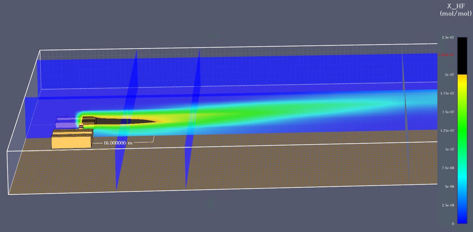
The above concentrations can be managed with maintaining a safety perimeter of 30m (as suggested by the Emergency Response Planning Guidelines (ERPG-3) for the concentration of HF), the remaining upwind, and gas masks.
6.8 LEAKAGE OF THE TRANSFORMERS’ OIL AND CONTAMINATED WATER RUNOFF.
Oil transformers and the water tank of 288kl has the risk of contaminated runoff water. The following measures are provided by the facility:
◼ Transformers:
◼ The MV/SUT (Medium Voltage/Step-up) transformers [18] [19] are self-bunded transformer that includes splash guards for AS1940 compliance, hence the oil will remain enclosed, preventing potential environmental damage and fire spread.
◼ The 330/33kV transformers have an oil/water separator and a bund with the capacity to hold 120% of the oil volume to account for water and overflow. This will also prevent potential environmental damage and fire spread.
Figure 29: HF Concentration with fire and wind (dark colour is more than 0.2ppm).
Orana
Battery Energy Storage System (BESS)
◼ Water runoff:
◼ Sediment ponds are provided in case water is used (refer to Appendix J)
6.9 ELECTROCUTION AND EMF HAZARDS.

Further assessment to electrocution and EMF hazards is out of the scope of this study. The assessment is to be provided by the facility.
This documentation is listed as a requirement in Section 8 of this document, and safety measures are to be added in the Emergency Management Plan.
It is recognized however that the site is provided masts for lighting protection.
6.10 FLAMMABLE LIQUIDS OR GASSES
Storage of flammable liquids or liquefied flammable gasses in tanks do not occur within this site, therefore this risk and associated events are not applicable to this study.


CONSEQUENCE ON INCIDENTS
This section assesses the consequences of fire given a fire of the BESS units, Substation and ancillary infrastructure. It is out of the scope of this report to include consequences related to financial impact, environment, legal and regulatory, community and property protection.
7.1 FIRE SPREAD ACCEPTANCE CRITERIA
◼ IEEE Std 979-2012:
Table B.3 of IEEE Std 979-2012 [26] gives some typical examples of the amount of radiant heat necessary to ignite common materials used in substations.
Table 5: Typical radiant heat flux intensities-based IEEE Std 979-2012 [26]
◼ AS 1530.4-2014:
Where other façade/lining materials are present in adjoining building or equipment, Table A3 of AS 1530.4-2014 [27] contains a listing of heat flux required for radiant ignition for piloted and unpiloted ignition. The heat flux (qcr) level for non-piloted ignition is taken as 25 kW/m2. Refer to table below.
Table 6: Typical radiant heat flux intensities based on AS 1530.4-2014.

The assessment methodology requires that a fire will not cause a received heat flux (qr) in excess of the critical heat flux (qcr) on the allotment boundary or equipment.
Acceptance will be demonstrated if qr < qcr
◼ Fire Brigade:
Acceptable threshold of radiation for Firefighter operations shall be a maximum of 3.0 kW/m2 from the ground level, level at which the fire brigade will perform fire brigade operations
◼ Equipment criteria:
Given the above critical heat flux criteria, the following criteria will be applied to each one the equipment or structure at the development:
Table 7: Critical heat flux criteria
Furthermore, the BESS Tesla Megapacks 2XL are also assessed with a critical temperature criterion to account a thermal runaway event (table below).
Orana Battery Energy Storage System (BESS)

Table 8: Critical temperature criteria
Equipment
Tesla Megapacks 2 XL 239 [11] [13]
7.2 FIRE CONSEQUENCE TO EQUIPMENT/FACILITIES

330KV HV Substation.
In order to assess the impact of a transformer fire on other objects, the transformer will be treated as a pool fire and will be assessed in accordance with AS2067.
Transformer pool fire:
The transformer fire treated as a pool fire is based on liquid hydrocarbon fire. The method used to calculate the heat flux received at a target was one that is generally accepted in the risk engineering discipline detailed in the Yellow Book (Committee for the Prevention of Disasters).
Enclosure Fire Dynamics gives a correlation equation (Equation 3.6) to estimate the free burn mass loss rate as below: ) (1 " " D
e m m = (Equation 3.6, Enclosure Fire Dynamics) [28]
Where:
◼ m : 0.039 kg/m2s [28]
◼ k : 0.7 (m-1) [28]
◼ D: diameter of the pool fire as a circle.

Figure 30: Extract Burning rate estimates [28].
It can be seen from the above equation the fire size in terms of mass loss rate and hence heat release rate is dependant of the area of the bund, which is designed in accordance with the oil volume of the selected transformer of the substation A liquid fuel pool fire in the transformer will be modelled using the NIST Fire Dynamics Simulator model.
Orana Battery Energy Storage System (BESS)

The National Institute of Standards and Technology (NIST) has been developing Fire Dynamics Simulator (FDS), to predict fire spread in a structure. Over the past few years, it has also been used to predict smoke and hot gas plume behaviour produced by outdoor fires. FDS is well documented and is widely used by fire protection engineers around the world. The model is being extended to include fire spread from structure to structure and generalizing FDS to include a means to predict fire spread in both continuous and discrete natural fuels.
The fire growth and spread were modelled using the National Institute of Standards and Technology (NIST) Fire Dynamics Simulator (FDS) software package and Smokeview which is used to view the results.
Fire Dynamics Simulator (FDS) is a computational fluid dynamics (CFD) model of fire-driven fluid flow. The software solves numerically a form of the Navier-Stokes equations appropriate for low-speed, thermally-driven flow with an emphasis on smoke and heat transport from fires.
In accordance with the methodology described above and considering the characteristics of the transformer of the substation, a bund of approximately 220m2 with a fire of 276MW (Figure 31) is estimated.
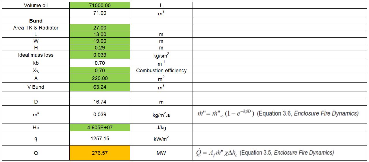
The HV transformer fire will be modelled with a size of 276MW and the following characteristics:
◼ Fire Origin: HV Transformer at substation.
◼ Fire growth: Instant.
◼ Weather conditions: Wind speed – 5.0m/s towards north; temperature – 30.9oC; Relative humidity – 58%.
◼ As per Appendix D, the transformer is provided with Mineral oil, hence the Hydrocarbon material is selected (transformer fires, properties obtained from Table 3-4.19 of SFPE handbook):
◼ REAC ID=”REAC”
▪ C=4.00 N=0.00
▪ H=10.00 HEAT_OF_COMBUSTION=4.605 x10⁷
▪ O=0.00
gr/gr
Figure 31: HRR Calculation Orana HV substation.
Orana Battery Energy Storage System (BESS)

The FDS model is presented in Figure 32 below and data regarding the model has been documented in the CFD/zone modelling form from the F7R NSW website (refer to Appendix F):
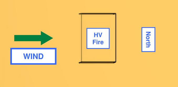
Figure 32 – FDS Model
Given the location of the subject facility equipment, Table 9 below summarizes the expected heat flux received at the equipment location within Orana BESS (Figure 33 and Figure 34).
Table 9: Heat flux results (Red is not acceptable)
Orana

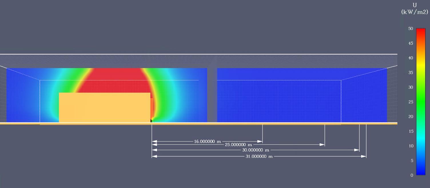
The results indicate that regardless the presence of wind, the maximum heat flux levels received at the different critical locations from a fire in at the substation are well below the critical heat flux for all equipment and buildings (Table 9). Hence, fire spread is not expected to occur or damage the proposed equipment/buildings.
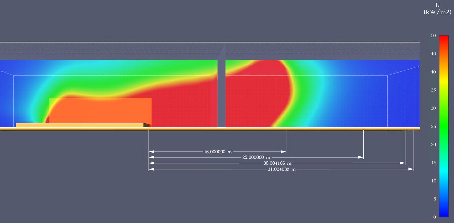
Figure 33: Radiant heat flux intensities without wind.
Figure 34: Radiant heat flux intensities with wind.
Orana
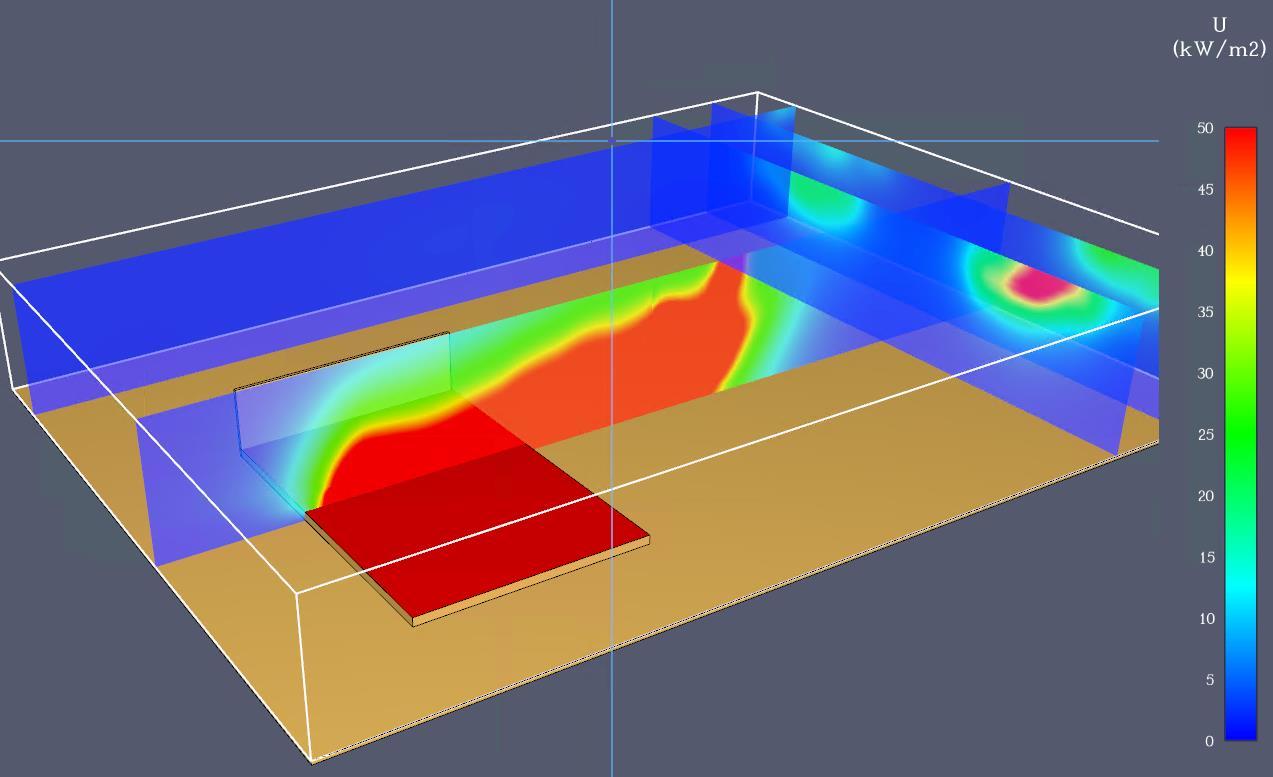

Further to the above, a fire hydrant system is also provided throughout the facility for fire brigade intervention procedures Where a HV transformer is on fire, the fire brigade can use the fire hydrant system to cool adjoining areas/vegetation/infrastructure if required while the main fire extinguish itself (i.e., not to attempt to extinguish the fire).
Also, conditions are considered for fire brigade intervention purposes. Based on the results of the model, fire brigade operations may be impacted within a critical distance of between 8m to 27m from the transformer due to a heat flux higher than 3.0 kW/m2 (Figure 36, Figure 37) above the Ground. However, these distances may be reduced due to the firewalls.
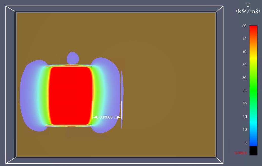
Figure 35: Radiant heat flux intensities with wind.
Figure 36: Radiant heat flux higher than 3kW/m2 without wind.

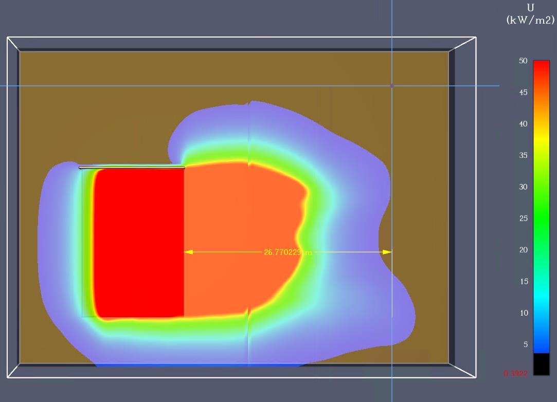
Figure 37: Radiant heat flux higher than 3kW/m2 with wind conditions.
Transformer location review as per AS2067:
Australian Standard AS2067-2016 is the most relevant standard with respect to the location of existing power utility infrastructure. The standard is based on oil transformer equipment and not batteries. However, the fire risk from a transformer is considered to be similar to that of a BESS.
The minimum separation distances are specified in AS2067 Table 6.1 below, considering that the transformers will use mineral oil and their oil capacity is expected to be 71,000 litres (71.0 m3).
Orana Battery Energy Storage System (BESS)

Table 10: AS 2067 Table 6.1
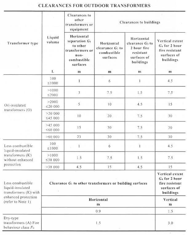
Table 11 below summarizes the distances of the HV transformers from the adjoining equipment where there is the main risk of fire spread, compared with the requirements of the Australian Standard AS2067.
Table 11: Distance assessment to HV Transformers

Equipment to assess
330KV HV Substation transformers
The above demonstrates that all the equipment have compliant distances between them in accordance with the Australian Standard AS2067, in order to mitigate the risk of fire spread.

MV/SUT transformers
The proposed Step-up transformers’ design is based on AS 60076 and IEC 60076.14 for High Temperature of Oil type KNAN (Natural Ester filled Cargill FR3) with an oil volume of 3,905L. The oil is Cargil FR3 Envirotemp Narutal Ester with a fire point greater than 300oC.
The transformer has enhanced protection and is a self-bunded transformer that includes splash guards for AS1940 compliance. The self-bund construction will prevent potential environmental damage and fire spread.
Australian Standard AS2067-2016 is the most relevant standard with respect to the location of existing power utility infrastructure. The minimum separation distances are specified in AS2067 Table 6.1 unless a fire rated wall is used to provide protection. Table 13 specifies that the proposed transformer must be located to not less than 0.9m from any equipment/facility.
Table 12 below summarizes the distances of the transformers from the adjoining equipment where there is the main risk of fire spread, compared with the requirements of the Australian Standard AS2067.
Table 12: Distance assessment to MV/SUT transformers
The above demonstrates that all the equipment have compliant distances in accordance with the Australian Standard AS2067, in order to mitigate the risk of fire spread.

13: AS 2067 Table 6.1

Furthermore, it is noted that the MV/SUT transformers exceed the requirements of the Australian Standard AS2067, given that is located to more than 1.5m from any equipment/facility and is provided with enhanced protection. The MV transformers could not be provided with enhanced protection and still comply with the AS 2067.
Orana
Table
Orana Battery Energy Storage System (BESS)

Further to the above, a Fire hydrant system is also provided throughout the facility for fire brigade intervention procedures. Where a SUT transformer is on fire, the fire brigade can use the fire hydrant system to cool adjoining areas/vegetation/infrastructure if required while the main fire extinguish itself (i.e., not to attempt to extinguish the fire).

Battery Fire - Large scale fire destructive test to BESS Megapack 2XL
Tesla performed a large-scale tests to the 3 test levels (i.e., cell, module and unit) in accordance with UL9540A [13] [11] [10], and also a large-scale fire destructive test.
The cell and module tests released flammable gasses, therefore the test to unit level was performed. The test at unit level was performed by Northern Nevada Research Center (NNRC). NNRC is a Tesla operated facility. For UL9540A unit level testing, the test was observed and certified by an NRTL. For both the UL9540A and Destructive test, the results and were reviewed by a licensed third-party fire protection engineer (i.e., Fisher Engineering and Fire & Risk Alliance)
NNCR performed the test to a Tesla MP2 on March 9, 2022, and was certified by TÜV (Technical Inspection Association). TÜV is an OSHA-approved NRTL and offers the cTUVus mark (i.e., canadian and US safety certification mark issued by TÜV Rheinland), which is equivalent to other NRTL marks such as UL, ETL or CSA
As described in the Fisher Engineering report (Appendix H), the test was performed on a Megapack MP2XL, where all the safety measures were disabled and the BESS was tested at the highest energy density used to induce the thermal runaway event (see pages 17 and 18 of the Fisher Engineering report - Appendix H). The initiating battery of the fire is shown in the figure below:

Forty-eight interior cells were simultaneously heated via thirty-two film heaters, as shown below, and the heaters were programmed to provide a heating rate of 5°C (9°F) per minute, as specified by UL 9540A. Note that the number of cells surpasses the requirements of the UL 9540A to create a severe fire scenario, given that previous large-scale tests to Unit Levels to MP2 as per the UL 9540A does not cause a large fire (see next section for further explanation about this test).
Figure 38: Initiating battery.

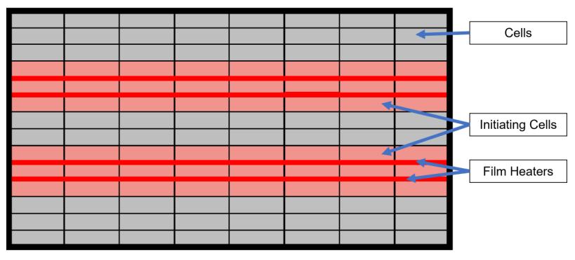
The timeline of events shows (figure below) that smoking starts after 1hr, then fire spreads by thermal runaway to 3 of the adjoining battery bays within the Megapack 2XL and finally flames start to decrease.
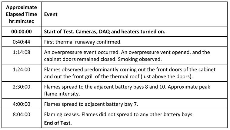
Some of the observations listed in the Fire Protection Engineering Analysis [13] are listed below (see page 37 of the Fisher Engineering report - Appendix H):
◼ The fire developed with 3.5m heigh flames and damaged only half of the BESS unit (adjoining bays), the bays on the other side remained unaffected. Also, the cabinet doors remained closed, no pressure waves or debris was ejected from the Megapack 2XL, and the pressure relief system prevented the deflagration event.
The above demonstrates that the Overpressure vents/Explosion control system will prevent a deflagration event.
Regarding the fire spread between Megapack 2XL, the large-scale test to unit level to the MP2 can be used, given that the above destructive test did not place adjacent units to the Megapack 2XL on fire
The report explains below how the unit test to Megapack 2 is applicable to a Megapack 2XL:
Figure 39: Heater location.
Figure 40: Timeline of events.
Orana Battery Energy Storage System (BESS)

“The MP2XL design is almost identical to the MP2 other than being greater in length to accommodate the additional battery modules. It uses the exact same cells, battery modules, and power electronics (i.e., all the same internal components) that the MP2 utilizes in its design. In addition, the design of cabinet itself, enclosure strength, and fire safety features, such as the BMS, site controller, monitoring, electrical fault protections, and explosion control system are nearly identical for the two products. Given the limited module propagation observed during UL 9540A unit level testing of the MP2 (seven cells went into runaway) the test results are expected to be no different for the MP2XL. As shown in Figure 16, if the test were run on the MP2XL, the same internal components (cells and battery modules) would be tested in the same location within the cabinet (i.e., surrounded by twelve battery modules until reaching the CIB). Furthermore, given the MP2XL is larger in volume, the deflagration risk in the test would be less as the flammable gas concentrations within the battery module bay would mixing with more ambient air and thus would be lower (see figure below).
Similarly, after reviewing the MP2 unit level fire test results and comparing the MP2 and MP2XL products to one another, TÜV determined the MP2 UL 9540A unit level fire test results can be applied to the MP2XL and an additional UL 9540A unit level fire test for the MP2XL was not required for its listing. As such, given all these factors, a standalone MP2XL unit level fire test was not performed, nor required. The UL 9540A unit level fire test results, described above for the MP2, can be applied to the MP2XL.”
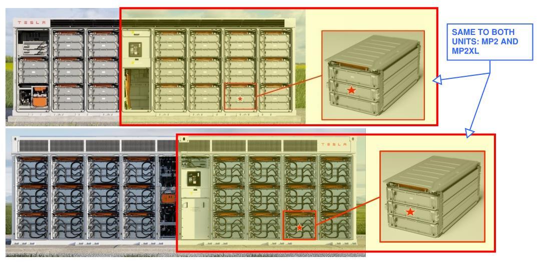
Given the above, even though the destructive test to MP 2XL did not place target BESS units, results from the Unit test to MP2 are acceptable. The Unit test to MP2 was set up as per UL9540A, whilst the destructive test to MP 2XL had to be overheat a bigger number of batteries surpassing the original requirements of the UL9540A because a larger fire was not caused under the current UL9540A standard.
As per the test UL9540A to Unit Level, it is required that at least 1 must be heated to cause thermal runaway, and thermal runaway must propagate to at least one other cell besides the initiating cell. To induce thermal runaway to more cells is optional, and the subject test to MP2 induced heated 6 cells and thermal runaway propagated to 3 battery modules, which complies with the requirements and objectives of the UL9540A to Unit Level.
The Megapack MP2 had the cells with film heaters as shown below as per UL9540A (Figure 42) and target Megapacks MP2 were place to the side, front and back of the MP2 on fire (Figure 43).
Figure 41: MP2 and MP2XL comparison.

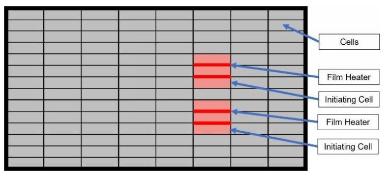
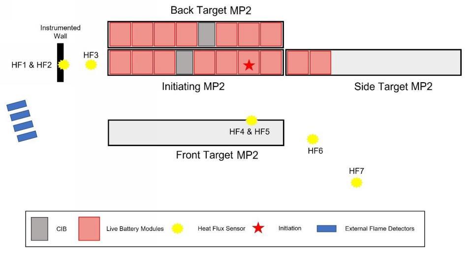
43: General test set-up – Target units and instruments (top view).
The timeline of events of the test is described below:
Figure 42: Initiating fire to MP2.
Figure

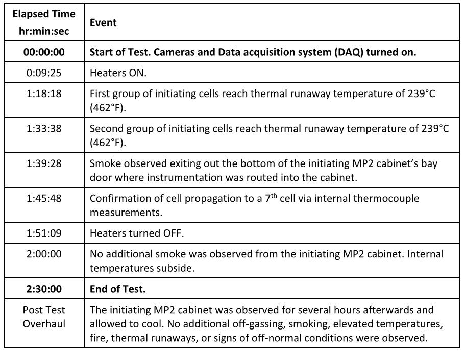
Figure 44: Events of the Unit level test to MP2.
The above timeline of events already suggests that this scenario is not likely to occur without having the attention of the staff and the safety procedures, considering that thermal runaway and smoke occur after 1.5hr, time at which those events can be detected with detectors and cameras on site. The test was performed with deactivated safety measures to allow thermal runaway to occur, however in a real scenario, all safety measures (Section 9 of this FSS) will be activated to prevent thermal runaway in a timeframe of 1.5hr.
The main results of the test to Unit level are listed below:
◼ Cell and module level UL 9540A testing demonstrated that flammable gases vent from the MP2/2XL cells during thermal runaway; however, they do not release toxic gases sometimes associated with the failure of lithium-ion batteries, such as HCN, HCL and HF [13].
◼ Unit level UL 9540A testing demonstrated that the MP2/2XL meets or exceeds all the performance criteria of UL 9540A, Table 9.1 and UL 9540A installation level testing is not required for a MP2/2XL installation. Six cells were simultaneous heated, they failed and extended the thermal runway to a seventh cell only. The failure did not result in any observations of explosion hazards, including but not limited to, observations of a deflagration, projectiles, flying debris, detonation, or other explosive discharge of gases [13]
Fire & Risk Alliance, LLC (FRA) and Tesla indicates that this seven-cell failure event is beyond what has been identified by Tesla’s DFMEA, which is based on extensive field data from all Tesla products (EVs and BESSs) and first-principles assessments as a worst-case scenario [10].
◼ Internal destructive unit level testing demonstrated that the MP2/2XL is capable of safely failing in the extreme case of a catastrophic failure of a battery module (the forced thermal runaway of 48 cells simultaneously). This destructive unit level test led to a slow progressing fire that burned for 6 hours and 40 minutes until flaming ceased, only consuming one-half of the battery modules in the cabinet [13]
Orana Battery Energy Storage System (BESS)

◼ Fire modelling demonstrated that, in the unlikely event of a fire, it would not propagate from one MP2/2XL cabinet to adjacent cabinets installed 6 inches behind, 6 inches to the side and 8 feet directly in front of the initiating MP2/2XL. This result was analysed for both no wind and worst-case wind conditions where flames could tilt towards the adjacent MP2/2XL cabinets [13].
◼ The MP2/2XL explosion control system can mitigate the deflagration hazard even with an extreme failure scenario of a battery module (the forced thermal runaway of 48 cells simultaneously) resulting in the MP2/2XL safely failing [13]
◼ An integral fire suppression system or an external fire suppression system is not required to stop the spread of fire from a MP2/2XL cabinet to adjacent MP2/2XL cabinets when installed at clearances of 8 feet in front, 6 inches behind and 6 inches to the sides [13] Orana BESS design proposes a separation of 8.3ft (2.547m) to the front Megapack 2XL and a separation of 9 inches to the back Megapack 2XL, which surpasses the required clearances by the BESS supplier (refer to below and to Appendix A); a clearance of 230mm between back-to-back Megapacks 2XL as required by the manufacturer, and a sideway clearance of 5050mm surpassing the manufacturer’s requirement (i.e., 150mm).
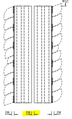
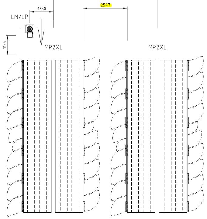
Figure 45: Clearances between Megapack 2XL (back – front units respectively).
◼ Manual fire suppression (hose lines) is not required to stop the spread of fire from a MP2 cabinet to adjacent MP2/2XL cabinets when installed at clearances of 8 feet in front, 6 inches behind and 6 inches to the sides [13] Orana BESS design proposes larger clearances as shown in Figure 45
◼ Based on a review of the MP2/2XL, its fire safety features, UL 9540A test results, additional internal MP2/2XL unit level fire testing and fire propagation modelling, the MP2/2XL can meet or exceed installation level codes and standards, such as the IFC and NFPA 855, required for outdoor, ground mounted BESS installations when installed in accordance with the MP2 and MP2XL Design and Installation Manual [13] Currently the MP2/2XL is listed to all product design standards (such as UL and IEC).
◼ “UL 9540A unit level fire testing of the MP2 demonstrated that an internal failure event causing thermal runaway of six cells nearly simultaneously will not propagate thermal runaway throughout the battery module. The nearly simultaneous failure resulted in thermal runaway propagating only to one additional cell and no further.” [13] (Figure 46)

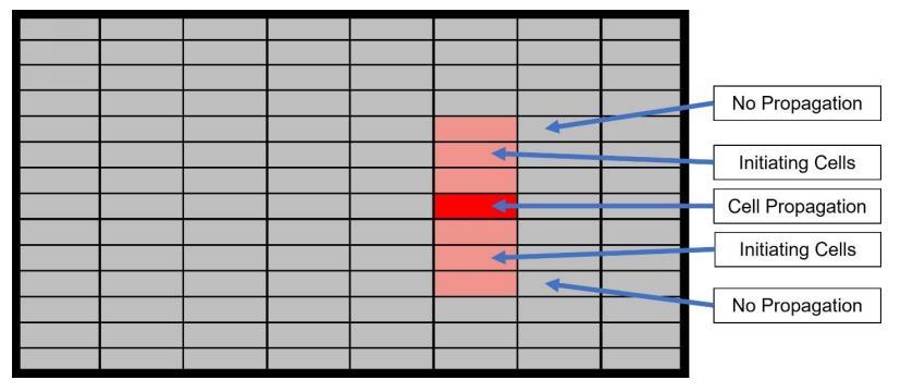
◼ “Surface temperatures of battery modules within the target MP2 cabinets adjacent to the initiating MP2 cabinet did not exceed the temperature at which thermally initiated cell venting occurs. The maximum temperatures recorded at the battery modules of the adjacent MP2 cabinets were 13.8°C (56.4°F) and 13.2°C (55.8°F). These temperatures are significantly below the temperature at which cell venting occurs (174°C or 345°F).” [13]. The temperature criteria indicated that thermal runaway would occur at 239°C (section 7.1). The test showed that this threshold is not reached at the adjoining Megapacks (it reaches up to 13.8°C) during the tests, and Fisher Engineering [13] also performed a thermal runaway model to demonstrate that critical temperatures in adjoining BESS units are not reached. It is recognized however that real fire events such as Bouldercombe (section 6.1.3), the back Megapack may affected and therefore it is better to be replaced (it is noted even though the back Megapack was affected, the effects did not caused fire spread level)
Given the results of tests and real events, the critical scenario is to be considered. Therefore, a Fire hydrant system is also provided throughout the facility for fire brigade intervention procedures. Where a Megapack 2XL is on fire, the fire brigade can use the fire hydrant system to cool adjoining Megapack if required while the main Megapack fire extinguish itself (i.e., not to attempt to extinguish the fire) to prevent any damage to adjoining Megapacks 2XL
◼ “Surface temperatures on exposures 5 ft (1.52 m) to the side and 8 ft (2.44 m) in front of the initiating MP2 cabinet did not exceed 97°C (175°F) above ambient. The maximum external surface temperatures recorded at the instrumented wall 5 ft (1.52 m) to the side was 25.9°C (78.6°F) with a temperature rise above ambient of 5.5°C (9.9°F). The maximum external surface temperatures recorded at the front target 8 ft (2.44 m) directly in front of the initiating MP2 was 16.8°C (62.2°F) with a temperature rise above ambient of 5.5°C (9.9°F). These temperatures are significantly below the maximum permitted temperature rise above ambient of 97°C (175°F).” [13]
Further to the above tests, Fire & Risk Alliance, LLC (FRA) performed a series of CFD models for Tesla to review the explosion control system.
The explosion control system is composed mainly by sparkers and overpressure vents:
◼ Sparkers are installed at the ceiling level of the IP66 battery module bay and towards the bottom of the cabinet. They are designed and programmed to spark regularly to ignite flammable gases that migrate to the top of the cabinet and any flammable gases that accumulate at other elevations within the cabinet, preventing the accumulation of combustible gases to a dangerous level [10]
Figure 46: Cell propagation during UL9540A unit level fire testing.

◼ The overpressure vents are designed to relieve the pressure inside the cabinet before the cabinet fails with a safety factor over 2. This is accomplished through the design of 27 overpressure vents that passively open at an internal cabinet pressure of 12 kPa. The enclosure strength of the MP2XL cabinet exceeds 24 kPa (i.e., 2 times safety factor as required by NFPA 68). Meaning, the overpressure vents open at less than one-half the cabinet strength. Once open, the overpressure vent will continue to ventilate the MP2XL cabinet throughout the duration of a thermal event, reducing the likelihood of additional flammable gas accumulation and deflagrations within the MP2XL during emergency response [10].
The following is the summary of their findings:
◼ The explosion control system design of the MP2XL meets or exceeds the requirements of NFPA 68 and can safely mitigate an internal overpressure during a thermal event via the 27 overpressure vents installed in the ceiling of the battery module bay [10]
◼ Tesla performed a series of CFD models to analyse the dispersion of combustible gases vented during the failure of seven cells within the MP2XL cabinet, as tested during UL9540A unit level testing [10]
◼ CFD modelling demonstrated that the design of the overpressure events of the MP2XL meets the requirements of NFPA 68 in the scenario of seven cells simultaneously going into thermal runaway [10]
◼ CFD modelling further demonstrated that the design of the overpressure events of the MP2XL still meets the requirements of NFPA 68 in the scenario of seven cells simultaneously going into thermal runaway even in the unlikely event of two sparkers failing inside the MP2XL cabinet [10]
◼ An internal gas detection system is not required to mitigate the risk of explosion within a MP2XL cabinet [10].
◼ Based on the CFD dispersion modelling, the sparker system does not permit the sustained accumulation of flammable gases above their flammable limits, either throughout the entire volume of the cabinet or within smaller partial volumes where a gas detection system would be warranted to detect such a scenario [10].
◼ The operation of the passive overpressure vents does not require a gas detection system to actuate their opening, as demonstrated during large-scale fire testing (see FPE report) [10].
◼ Internal gas/fire detection is not necessary to limit fire propagation from one MP2XL cabinet to adjacent MP2XL cabinets, as demonstrated by large-scale fire testing and fire propagation model (see FPE report) [10]
Further to the above fire spread analysis, the assessment of toxic gasses is also reviewed.
In accordance with the test results summarized by Fisher Engineering [13], “Internal unit level products of combustion testing demonstrated that HF was only detected at trace levels (0.10 and 0.12 ppm) in two sampling locations (approximately 20 feet upwind and 5 feet downwind from the MP2/2XL) when six cells within MP2/2XL cabinet were forced into thermal runaway. This trace quantity of HF was detected over the entire 2½ hour test duration (i.e., it was the cumulative quantity detected) and is well below the Immediately Dangerous to Life or Health (IDLH) value of 30 ppm for HF. The testing also found no traces of twenty-seven different metals, including lithium and mercury”.
Other studies indicate that low concentrations of HF (e.g., 0.2-0.7 ppm) can cause irritation and mild symptoms, and higher concentrations (e.g., > 3 ppm) can cause severe burns, respiratory damage, and even death [25]
The above HF concentrations, which are more exigent than the thresholds described by Fisher Engineering, are still higher than what was measured during the test at 20 feet (6.0m).
Considering that the closest residential areas are located to more than 0.9km to the west and more than 1km to the north-east sides, it is expected that even lower concentrations than 0.12ppm or negligible concentrations can potentially reach the residential areas, and therefore those will not harm residents.
Orana Battery Energy Storage System (BESS)

Battery Fire – Fire spread analysis to adjoining equipment/buildings

As demonstrated in the section above and as per the requirements of the Tesla, the Megapack 2XL BESS supplier [1], clearances of 2440mm to the front and 150mm to the sides must be maintained to prevent any damage to an adjoining BESS, and therefore to another equipment.
The equipment/facilities clearances from a Megapack 2XL are listed in below, and it shows that the proposed clearances comply to mitigate the risk of fire spread/damage.
Table 14: Megapack 2XL clearances
Equipment/facility
Furthermore, additional assessment can be performed based on the heat flux criteria described in Section 7.1. The model calculated the heat flux at different distances from a Megapack 2XL (Figure 47), which can be used to assess the risk of fire spread to adjoining equipment/facilities.
“These heat fluxes were calculated utilizing the solid flame radiation model formulas described by Hurley and heat transfer formulas between parallel, rectangular plates (i.e., the exterior surfaces of adjacent MP2/2XL cabinets are two parallel, rectangular plates separated by 6 inches) outlined by Howell”. It is recognized that a battery fire is not the same as a pool fire, however Telsa’s modelling is consistently conservative by overpredicting the heat flux compared to the testing results. The models provide worst case heating results as stated in the reports. The model also applies a consistent external surface temperature instead of hotspots, emitting a larger radiative heat flux than what would be seen in testing. Beyond the inherent conservatism in the models, Tesla also pursued modelling the flames at a 45-degree angle to consider worst case wind conditions. Overall, there are many layers of conservative assumptions that build confidence in the modelling results.

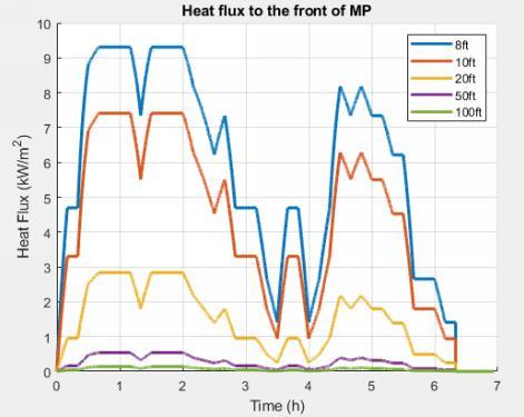
Figure 47: Heat flux at the front of a Megapack 2XL at different distances.
Considering the distances between equipment/facilities designed as per the plans in Appendix A, Table 15 shows that given a fire to a Megapack 2XL, fire is not predicted to spread or to damage any of the adjoining equipment/facilities.
Table 15: Heat flux criteria from a Megapack 2XL
Nonetheless the above, a Fire hydrant system is also provided throughout the facility for fire brigade intervention procedures. Where a Megapack 2XL is on fire, the fire brigade can use the fire hydrant system to cool adjoining areas/vegetation/infrastructure if required while the main fire extinguish itself (i.e., not to attempt to extinguish the fire) to prevent the risk of fire spread from a Megapack 2XL fire.

Fire in other Area of the facility (i.e., O&M building, Control building, storage shed, RUMs and SWG Buildings)
Further to the equipment above, the facility contains an Operations & Maintenance building, storage sheds, RMUs and two SWG Buildings. The fire associated with these buildings are considered to be no greater than a small office type building. The closest building is located approximately 17m from the BESS boundary.
Based on the International Fire Engineering Guidelines the likelihood of an office fire is 6.2x10⁻³ per year and a fire size of approximately 250kW/m2. Accordingly, the peak fire size is predicted to be 23MW assuming adequate ventilation.

Given the separation distances to the battery units/Megapacks and other areas of over 6m it is considered that the risk of fire spread is extremely low and significantly less than that for a building with NCC compliant separation distances (3m to the boundary and 6m between buildings) that are considered to represent the community acceptance level for fire spread.
To demonstrate that the risk of fire spread is not expected to occur from a fire to those buildings to another building/equipment within the facility, the potential for fire spread between buildings is to be based on the calculated radiant heat received by the subject building/equipment. The basis of the assessment is that the potential of fire spread should be within the limits for critical heat flux listed in Section 7.1.
The following assumptions have been made for the adopted values:
◼ The emitting surface is any of the subject buildings (i.e., O&M building, storage sheds and SWG Buildings).
◼ Emissivity value of 0.9 has been assumed for the flame. This is considered to be ‘reasonable’ assumption as detailed in Section 7.5 of the Fire Engineering Design Guide.
◼ The temperatures proposed for the emitting surfaces will be 840°C as a conservative measure. Based on the UK Approved Document B [29]
The radiant heat emitted from the boundary to the opening will be determined via the following radiation formula detailed in the International Fire Engineering Guidelines (Section 2.4.2.3). qr = Φ Es S Tf 4
where:
qr is the radiant heat flux received (kW/m²)
Φ is the configuration factor
Es is the emissivity of the emitter
S is the Stefan Boltzman Constant = 56.7 x 10⁻¹² (kW/m² K4)
Tf is the temperature of the emitting surface (K)
The location of the parallel openings is determined and calculated as shown in Figure 48 below
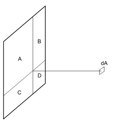

Figure 48 – Parallel Panel and Configuration factor
Given the methodology described above, heat flux results to adjoining buildings/equipment with the critical criteria are summarized in Table 16 below:

Table 16: Heat flux results from building fires
The results indicate that maximum heat flux levels received at receiving buildings/equipment are well below the critical heat flux. Therefore, the fire spread, or equipment damage is unlikely to occur.
Further to the above, a Fire hydrant system is also provided throughout the facility for fire brigade intervention procedures. The fire brigade can use the fire hydrant system to cool adjoining areas/vegetation/infrastructure if required while the main fire extinguish itself (i.e., not to attempt to extinguish the fire).

Fire in adjacent Allotments
The adjacent allotments are agricultural production lands, and the subject site is approximately 60m away from the closest allotment.

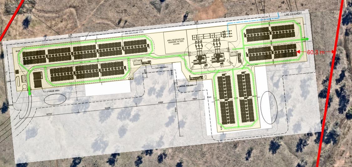
The NCC allows non-load bearing openings within buildings to be 3m from the boundary or 6m from another building on the same allotment. Given the separation distances of the battery units from the boundary (i.e., 60m) it is considered that the likelihood of a fire and the consequence are no worse than in the general community.
Also, the subject allotment and BESS are out of the flood and BPA (Bush Fire Prone) areas in accordance with the NSW Planning portal (Figure 13) [4]. Therefore, no BAL (bushfire assessment level) assessment is required to be addressed in this document in accordance with the AS3959-2018.
Nonetheless, if a grassfire occurs, a Fire hydrant system is also provided throughout the facility for fire brigade intervention procedures and control the fire spread of a grassfire.
Figure 49: Distance from BESS to closest boundary.


FIRE PREVENTION STRATEGIES/MEASURES
As part of the risk assessment, the following recommendations are to be implemented to satisfy the objectives of the relevant authorities and the client.
Akaysha Energy Pty Ltd., as the developer of the projects has agreed to comply with the below requirements to achieve the required level of safety (refer to Appendix K).
Refer to Appendix A for overall floor plans indicating the main Fire Engineering Requirements.
1. A firebreak of at least 10m wide must be designed and maintained as shown in Appendix A (this is compliant in the proposed layout in Appendix A).
2. The five (5) metre perimeter road within the perimeter fire break (as shown in Appendix A) must be maintained and must comply with the following:
◼ To withstand a uniformly distributed load over the entire area of 7 kPa or 0.7 tonnes/m2 and a continuous water discharge from a fire brigade appliance. (This is to prevent the pumper from being undermined by water issuing from the appliance over an extended period.)
3. The clearances between equipment must be maintained as per Appendix A and as listed below to mitigate the risk of fire spread.
Table 17: Clearances to maintain between equipment
4. The transformer at the 330KV HV Substation must be located at not less than 15m from any of the adjoining buildings which have combustible façade or be surrounded by firewalls as defined by AS2067 where these clearances can't be achieved.
5. As per AS2067, firewalls must be provided between HV transformers (a firewalls to each one of the HV transformers) as shown in Appendix A, Appendix D and the figures below:


Figure 50: Firewalls between transformers (plan view).

Figure 51: Firewalls between transformers (elevation).
6. The HV transformers (330/33kV transformers) will have a bund which hold 120% of the oil volume to account for water and prevent overflow.
7. MV/SUT transformers located in accordance with the proposed layout in Appendix A must be provided with enhanced protection.
8. All buildings within the facility must comply with the performance requirements of the NCC where the DtS provisions are not satisfied.
9. Develop a Fire Management Plan [5]. The HIPAP No.1 Emergency Planning [6] (not limited to) may be used as an example to develop the plan with the Industrial Lithium-Ion Battery Emergency Response Guide [2] from Tesla INC. Other items to include are the following:
◼ Post-incident clean-up disposal.
◼ As part of the PPE for Emergency procedures, firefighters should wear self-contained breathing apparatuses (SCBAs) and structural firefighting gear as per the requirements of the Tesla Response Guide [2]
Orana Battery Energy Storage System (BESS)

◼ Safety measures for potential and identified hazards (e.g., electrical, EMF, fire, environmental, ecological, noise, bushfire, leakage, social, etc) must be documented a spart of the Emergency Management Plan.
◼ Evacuation Plans.
◼ A bushfire management plan.
◼ Access restriction to the substation when it is on.
◼ Emergency contact details.
◼ Roles and responsibilities.
◼ Emergency muster points.
◼ Induction, training, drills.
◼ Public and mass media management.
10. Where transformers are oil-insulated, transformers shall use an FR3 (or similar) Ester oil where practical in lieu of the normal mineral oil.
11. The fire safety measures for the BESS Units will be the following:
◼ Overpressure vents/Explosion control system. “The overpressure vents are designed to open when subjected to an overpressure of 12 kPa or 250 pounds per square foot (psf), whereas the steel, IP66 battery module bay enclosure has an enclosure strength of 30 kPa (626 psf). Meaning, during an overpressure event inside the MP2 cabinet, the overpressure vents will open when subjected to an overpressure of approximately 12 kPa (250 psf), well before the integrity of the enclosure itself becomes compromised at 30 kPa (626 psf) with a 2.5 times safety factor.” [10]
◼ Remote shutdown provisions.
◼ Electrical fault protection devices: The MP2/2XL have several passive and active safety control mechanisms installed within the battery module circuit and distribution circuit that would be available to interrupt a fault current. These include the Battery module overcurrent protection, Inverter DC protection, Inverter AC protection, the Ground fault protection, and lightning strike protection [1], and an internal safety circuit called an enable circuit (also known as HVIL - high-voltage interlock loop) that shuts down all major power components when other faults are detected [13]
◼ Battery Management system (BMS): The BMS is engineered to react to fault conditions in an autonomous manner, with safeguards built into the firmware. These fault conditions include, but are not limited to, overtemperature, loss of communication, over-voltage, and isolation. For instance, to prevent a cell overtemperature the TMS is enabled by the BMS to cool the cells/module. This action by the BMS (which is just one example of many ways the BMS can respond to a fault condition) can either prevent thermal runaway from occurring in the cell or prohibit the propagation of thermal runaway to adjacent cells. Depending on the severity of the fault condition, the BMS can automatically isolate the affected battery module temporarily (less severe fault) or it can permanently disconnect the module [13]
◼ Thermal management system (TMS): The thermal management system (TMS) provides a suitable operating temperature for MP2 using liquid cooling via a 50/50 mixture of ethylene glycol and water and R-134a refrigerant. The TMS contains a closed-loop liquid cooling system that circulates liquid coolant throughout the battery modules and power electronics to maintain an optimum operating temperature [13]

◼ Site Controller and Monitoring: The MP2/2XL has 24/7 remote monitoring, diagnostics, and troubleshooting capabilities, and also has a local Supervisory Control and Data Acquisition (SCADA) system. All faults are transmitted to a Tesla LOC, alerting them to off-normal conditions that may require corrective action, either through remote means or an in-person field service visit. This communication link is accomplished via the Tesla Site Controller (TSC). The TSC provides the single point of interface for the utility, network operator, and/or the customer’s SCADA systems to control and monitor the entire energy storage site [13]
12. The O&M Building, Control building and Switchgear buildings will be provided with a smoke detection and alarm system as per AS1670.1 that will trigger the General Fire Alarm (GFA) throughout the O&M Building to alert all occupants. The smoke detection and alarm system must be connected to an FIP which will provide a local alarm through an Scada system (i.e., NOT connected to a fire station or fire dispatch centre in accordance with AS 1670.3).
13. During the operation stage, all vehicles must carry at least a nine (9)-litre water stored-pressure fire extinguisher with a minimum rating of 3A.
14. The site must be provided with Portable fire extinguishers as per AS 2444 (Section 10).
19. Water storage with not less 288kL must be provided an entrance to the facility with a compliant hard stand and booster assembly in accordance with the latest CFA Guidelines Revision 4 [3] as follows:
◼ Water access points must be clearly identifiable and unobstructed to ensure efficient access.
◼ Static water storage tank installations must comply with AS 2419.1-2021: Fire hydrant installations – System design, installation and commissioning.
◼ The static water storage tank(s) must be an above-ground water tank constructed of concrete or steel.
◼ The static water storage tank(s) must be capable of being completely refilled automatically or manually within 24 hours.
◼ The static water storage tanks must be located at vehicle access points to the facility and must be positioned at least ten (10) metres from any structure.
◼ The hard-suction point must be provided, with a 150mm full bore isolation valve equipped with a Storz connection, sized to comply with the required suction hydraulic performance.
◼ Adapters that may be required to match the connection are: 125mm, 100mm, 90mm, 75mm, 65mm Storz tree adapters with a matching blank end cap to be provided.
◼ The hard-suction point must be positioned within four (4) metres to a hardstand area and provide a clear access for emergency services personnel.
◼ An all-weather road access and hardstand must be provided to the hard-suction point. The hardstand must be maintained to a minimum of 15 tonne GVM, eight (8) metres long and six (6) metres wide or to the satisfaction of the CFA.
◼ The road access and hardstand must be kept clear at all times.
◼ The hard-suction point must be protected from mechanical damage (e.g., bollards) where necessary.
◼ Where the access road has one entrance, a ten (10) metre radius turning circle must be provided at the tank.
◼ An external water level indicator must be provided to the tank and be visible from the hardstand area.
Orana
◼ Signage indicating ‘FIRE WATER’ and the tank capacity must be fixed to each tank.

◼ Signage must be provided at the entrance to the facility, indicating the direction to the static water tank.
20. A Fire hydrant system must be provided in accordance with AS 2419.1-2021: Fire hydrant installations, Section 3.9: Open Yard Protection. The location of hydrants must be designed as follows:
◼ Be located not less than 27.0m from the HV transformers of the Substation.
◼ The hydrants will be located such that all infrastructure can be covered by at least 2 hydrants.
15. Warning signs must be provided as per Clause 5.3.3 of FRNSW BESS Guideline [4] as applicable (based upon site assessment). Some signage includes the following examples (not limited to):
◼ Exit signs.
◼ First aid firefighting equipment (fire hydrants, water storage tanks, fire extinguishers, etc.).
◼ Electrical hazards (e.g., high voltage).
◼ Equipment use instruction signs.
◼ Entrances to the facility and buildings (e.g., RMUs, SUT, SWG, Control building, etc.).
◼ Presence of chemical hazards.
◼ Toilets and facility related signs.
◼ Rescue and resuscitation signs.
◼ Fire exit doors.
◼ Restricted personal access to specific areas/buildings.
◼ Name to equipment/enclosures (e.g., RMUs, SUT, SWG, Control building, etc.).
16. All gates to alternative entrances to the main entry must be provided with 003-key padlocks to facilitate the access of the Fire Brigade.
17. A containment and management plan of contaminated fire water runoff from the BESS is to be developed by the facility.
18. The site will be provided with CH52 Verkada Multisensor Cameras and CP63 Verkada PTZ Cameras to facilitate remotely the overview of all the facility (Section 10).


DETAILS OF DETECTION AND PROTECTION
This section describes the fire detection systems throughout the facility and equipment All fault detection is Scada alarmed and hence notified to the operators to proceed according to the relevant procedures.
9.1 DETECTION SYSTEMS

Megapack 2XL.
The Tesla Megapack 2XL is provided with multiple safety measures such as the following [13]:
◼ Battery Management system (BMS):
The BMS is engineered to react to fault conditions in an autonomous manner, with safeguards built into the firmware. These fault conditions include, but are not limited to, over-temperature, loss of communication, overvoltage, and isolation. For instance, to prevent a cell over-temperature the TMS is enabled by the BMS to cool the cells/module. This action by the BMS (which is just one example of many ways the BMS can respond to a fault condition) can either prevent thermal runaway from occurring in the cell or prohibit the propagation of thermal runaway to adjacent cells. Depending on the severity of the fault condition, the BMS can automatically isolate the affected battery module temporarily (less severe fault) or it can permanently disconnect the module.
◼ Thermal management system (TMS):
The thermal management system (TMS) provides a suitable operating temperature for MP2 using liquid cooling via a 50/50 mixture of ethylene glycol and water and R-134a refrigerant. The TMS contains a closed-loop liquid cooling system that circulates liquid coolant throughout the battery modules and power electronics to maintain an optimum operating temperature.
◼ Overpressure vents/Explosion control system:
“The overpressure vents are designed to open when subjected to an overpressure of 12 kPa or 250 pounds per square foot (psf), whereas the steel, IP66 battery module bay enclosure has an enclosure strength of 30 kPa (626 psf). Meaning, during an overpressure event inside the MP2 cabinet, the overpressure vents will open when subjected to an overpressure of approximately 12 kPa (250 psf), well before the integrity of the enclosure itself becomes compromised at 30 kPa (626 psf) with a 2.5 times safety factor.”
◼ Site Controller and Monitoring:
The MP2/2XL has 24/7 remote monitoring, diagnostics, and troubleshooting capabilities, and also has a local Supervisory Control and Data Acquisition (SCADA) system. All faults are transmitted to a Tesla LOC, alerting them to off-normal conditions that may require corrective action, either through remote means or an in-person field service visit. This communication link is accomplished via the Tesla Site Controller (TSC). The TSC provides the single point of interface for the utility, network operator, and/or the customer’s SCADA systems to control and monitor the entire energy storage site.
◼ Electrical Fault protection devices:
The MP2/2XL have several passive and active safety control mechanisms installed within the battery module circuit and distribution circuit that would be available to interrupt a fault current. These include the Battery module overcurrent protection, Inverter DC protection, Inverter AC protection, the Ground fault protection, and lightning strike protection, and an internal safety circuit called an enable circuit (also known as HVIL - highvoltage interlock loop) that shuts down all major power components when other faults are detected.


Switchgear buildings.
The Switchgear buildings are provided multiple electrical fault detection systems [14] [15]
They will also have a smoke detection and alarm system as per AS1070.1 with an FIP at the entrance of the O&M building.

RMUs
The RMUs are provided multiple electrical fault detection and safety systems such as arc protection systems, fault detection and isolation mechanisms, remote monitoring capabilities, automated shutdown procedures, and interlocking mechanisms

Transformers.
The HV transformers (330/33kV transformers) have electrical protection [18] [19] and will have a bund which hold 120% of the oil volume to account for water and prevent overflow.
The MV/SUT transformers are self-bunded transformers with FR3 ester oil and are provided with enhanced protection. The self-containment and the high fire point of the FR3 ester oil will mitigate the risk of fire spread to the degree necessary.

O&M Building, Control Building and Storage sheds
Those buildings will be provided with a smoke detection and alarm system as per AS1070.1 with an FIP at the entrance of the O&M building.
The smoke detection will trigger the General Fire Alarm (GFA) throughout the O&M Building to alert all occupants and will be connected to an FIP which will provide a local alarm through an Scada system (i.e., NOT connected to a fire station or fire dispatch centre in accordance with AS 1670.3).
9.2 PROTECTION SYSTEMS
It was demonstrated in Section 7 that there is no risk of fire spread between equipment/buildings, and all buildings are less than 500m2 and separated from each other by more than 6m as the NCC DtS provisions, mitigating to the degree necessary the risk of fire spread
However, in order to consider any emergency, the facility will be provided with a reticulated fire hydrant system throughout the facility in accordance with AS2419.1 (Appendix I) fed from static water tanks (see Figure 53 below)
In addition to the water tank, the whole development will be provided with 5kg CO2 Portable fire extinguishers as per AS 2444 (Section 10), and during the operation stage, all vehicles must carry at least a nine (9)-litre water storedpressure fire extinguisher with a minimum rating of 3A.

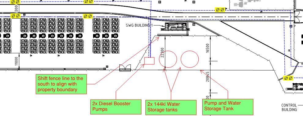
Orana Battery Energy Storage System (BESS)
Figure 52: 288kl water storage location.
Orana Battery Energy Storage System (BESS)

DETAILED DRAWINGS OF FIRE SERVICES LAYOUT
The following fire services drawings are attached in Appendix I:

◼ CH52 Verkada Multisensor Cameras and CP63 Verkada PTZ Cameras to facilitate remotely the overview of all the facility.
◼ 5kg CO2 Portable fire extinguishers as per AS 2444 for early attempt of extinguish a fire.
◼ Water storage of 288kl at an entrance of the development (see Figure 53 below) for fire brigade intervention procedures.

Figure 53: 288kl water storage location.
◼ A reticulated fire hydrant system compliant with the AS2419.1 for fire brigade intervention procedures, where any infrastructure within the facility will be reached by at least 2 hydrants.


CALCULATIONS FOR FIRE-FIGHTING WATER
As per the latest CFA Guidelines Revision 4 [3], for facilities with battery energy storage systems, the fire protection system must include at a minimum, where reticulated water is available, a fire hydrant system that meets the requirements of AS2419.1-2021: Fire hydrant installations, Section 3.9: Open Yard Protection, and Table 2.2.5.(D): Number of Fire Hydrants Required to Flow Simultaneously for Protected Open Yards. Except, that fire hydrants must be provided and located so that every part of the battery energy storage system is within reach of a 10m hose stream issuing from a nozzle at the end of a 60m length of hose connected to a fire hydrant outlet.
AS2419.1-2021 - Table 2.2.5.(D) is reproduced below:
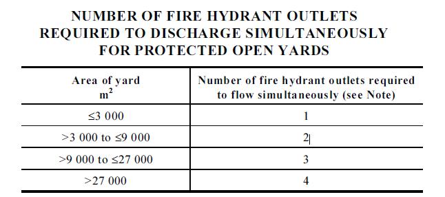
The facility site is more than 500,000m2 within the security fence and the distribution of the equipment is as shown in Appendix A
In accordance with the CFA guidelines, the yard area “may be considered that of the battery installation, including the minimum 10m fire break around the battery infrastructure, rather than the entire area of the yard or site”. Hence, given the previous fire spread risk review (see section 7, which demonstrates that fire spread is not likely to occur between BESS), the “yard area” will be defined as one of the battery arrays that are separated 13m from each other (see figures below).

Figure 54: “Yard area” definition from western BESS yard.

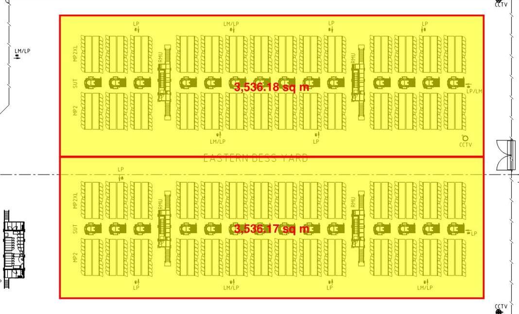
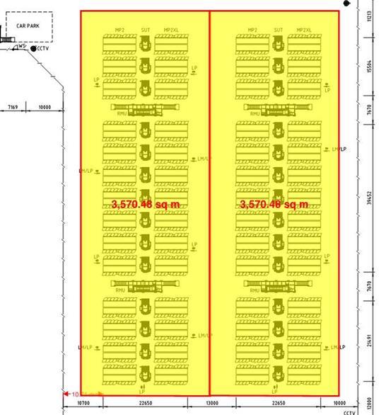
Figure 55: “Yard area” definition from eastern BESS yard.
Figure 56: “Yard area” definition from southern BESS yard.

Each one of the above battery arrays has an area of between 3,000m2 to 9,000 m2. Accordingly, 2 hydrants running for 4 hours at 10L/s are required by the AS 2419.1-2021 for a BESS development
The water storage tank is therefore required to allow for 2 hydrants at 10L/s each for four hours, i.e., 288kL.
The fire hydrants will be located so any infrastructure within the facility should be able to be reached by at least two hydrants, in case one of the hydrants is not accessible due to fire hazard conditions.
Orana Battery Energy Storage System (BESS)
Orana Battery Energy Storage System (BESS)


ARRANGEMENTS FOR CONTAINING CONTAMINATED FIRE FIGHTING WATER
Oil transformers and the water tank of 288kl have the risk of contaminated runoff water. The following measures are provided by the facility:
◼ Transformers:
◼ The MV/SUT (Medium Voltage/Step-up) transformers [18] [19] are self-bunded transformer that includes splash guards for AS1940 compliance, hence the oil will remain enclosed, preventing potential environmental damage and fire spread.
◼ The 330/33kV transformers have an oil/water separator and a bund with the capacity to hold 120% of the oil volume to account for water and overflow. This will also prevent potential environmental damage and fire spread.
◼ Water runoff:
◼ Sediment ponds are provided in case water is used (refer to Appendix J).
Battery Energy Storage System (BESS)

FIRST AID FIRE PROTECTION

The following first aid fire protection equipment and operational arrangements are part of the safety measures of the BESS Facility:
◼ Portable fire extinguishers as per AS 2444 (Section 10).
◼ Warning signs (e.g., exit signs, placarding and first aid fire-fighting equipment use instruction signs) as per Clause 5.3.3 of FRNSW BESS Guideline [4]
◼ Training of operators/staff who will proceed in accordance with the Fire management plan and the equipment manuals.
◼ A firebreak of at least 10m wide is maintained as shown in Appendix A.
◼ During the operation stage, all vehicles must carry at least a nine (9)-litre water stored-pressure fire extinguisher with a minimum rating of 3A.
◼ A reticulated fire hydrant system compliant with the AS2419.1 for fire brigade intervention procedures, where any infrastructure will be reached by at least 2 hydrants fed from static water tanks
Orana


NSW RELEVANT GUIDELINE: FIRE SAFETY GUIDELINE TECHNICAL INFORMATION D22/107002
This guideline outlines the Fire and Rescue NSW (FRNSW) considerations relating to the assessment and determination of fire safety studies (FSS) for facilities containing large-scale lithium battery storage systems (LiBESS).
◼ Clause 5.1: Assessment of potential consequences of credible incidents.

This document identified the hazards and their likelihood in Section 6, and the quantification of the consequences has been addressed in Section 7. Failures to the existing equipment/buildings and the risk of fire spread and/or explosion was considered.
Consequences of fire to all equipment and buildings are addressed in Section 7, and large scale tests as per UL9540A to all levels (i.e., cell, module an unit) have been explained, which include fire safety systems disabled and the Megapack2XL on fire.

This document identified the hazards and their likelihood in Section 6, and the quantification of the consequences has been addressed in Section 7. Failures to the existing equipment/buildings and the risk of fire spread and/or explosion was considered where applicable.
Release of contaminant gasses from the Megapacks, the leakage of the transformers’ oil and contaminated water runoff are considered in this FSS.
The development of this document is considered to comply with this requirement where hazards are identified, and safety measures are specified.
Orana Battery Energy Storage System (BESS)

This document identified the hazards and their likelihood in Section 6, and the quantification of the consequences has been addressed in Section 7. Failures to the existing equipment/buildings and the risk of fire spread and/or explosion was considered where applicable.
For the Megapacks 2XL BESS, past events to Tesla Megapacks and large-scale tests as per UL9540A to all levels (i.e., cell, module and unit) have been explained, which include fire safety systems disabled and the Megapack 2 on fire.
The management of chemical components and environmental impact are not part of the scope of this document, and it must be provided by the BESS development.
◼ Clause 5.2: Defining Fire Safety Strategy.


The fire management plan for the BESS is provided for the supplier in the Industrial Lithium-Ion Battery Emergency Response Guide. Tesla INC. revision 2.6, 2022 [2].
Further evidence to support the strategy is provided in the development of this report and referenced documentation (see section 7, Appendix G and Appendix H).
The fire safety strategy is also described in detail in section 5.2.4 of this document.
Orana Battery Energy Storage System (BESS)

The strategy does not rely solely on the intervention of the fire brigade, redundant protection measures are provided to the Megapacks as follows (refer to section 9 for more details).
◼ Cabinets.
◼ Customer interface bay (CIB).
◼ Battery Management system (BMS).
◼ Thermal management system (TMS).
◼ Overpressure vents/Explosion control system.
◼ Site Controller and Monitoring.
◼ Electrical Fault protection devices.
◼ Remote shutdown provisions.
Further to the above, the equipment manufacturer’s strategy is to monitor the BESS fire and allow it to selfextinguish. Evidence is provided in Section 7.2 , Appendix G and Appendix H.
Also, a fire hydrant system throughout the facility is provided in accordance with AS2067.1-2019, which will be fed from a water storage of 288kl for fire brigade intervention procedures.
◼ Clause 5.3: Electrical hazards posed to firefighters.
The electrical risk assessment is out of the scope of this document, and it must be provided by the BESS development. However, where electrical faults lead to a fire event, this hazard and its likelihood is addressed in Section 6, and the quantification of the consequences has been addressed in Section 7 with the assessment of heat flux and large scale tests.
The role of the fire brigade in an emergency is explained in Section 5.2 and will be part of the Site Emergency Management Plan [5].


This document has specified that warning signs must be provided as per Clause 5.3.3 of FRNSW BESS Guideline [4] as applicable (based upon site assessment). Some signage includes the following examples (not limited to):
◼ Exit signs.
◼ First aid firefighting equipment (fire hydrants, water storage tanks, fire extinguishers, etc.).
◼ Electrical hazards (e.g., high voltage).
◼ Equipment use instruction signs.
◼ Entrances to the facility and buildings (e.g., RMUs, SUT, SWG, Control building, etc.).
◼ Presence of chemical hazards.
◼ Toilets and facility related signs.
◼ Rescue and resuscitation signs.
◼ Fire exit doors.
◼ Restricted personal access to specific areas/buildings.
◼ Name to equipment/enclosures (e.g., RMUs, SUT, SWG, Control building, etc.).
◼ Clause 5.4: Fire Brigade intervention.
The role of the fire brigade in an emergency is explained in Section 5.2 and will be part of the Site Emergency Management [5]
Furthermore, this FSS will be shared with the Fire and Rescue NSW, so the Fire and Rescue NSW can comply with this duty.

This document identified the hazards and their likelihood in Section 6, and the quantification of the consequences has been addressed in Section 7. “Hazardous materials” are not identified or listed in development.

The role of the fire brigade in an emergency is explained in Section 5.2 and will be part of the Site Emergency Management Plan [5].
It is stated that The Fire Brigade will assist to site upon the call of the BESS operators, and operators will accompany the Fire Brigade to procced as required by the procedures of the suppliers or the Emergency Management Plan.
The role of the fire brigade in an emergency is explained in Section 5.2 and will be part of the Site Emergency Management Plan [5]
Furthermore, this FSS will be shared with the Fire and Rescue NSW, so the Fire and Rescue NSW can comply with this duty.
Orana Battery Energy Storage System (BESS)

The development of the emergency plan is to be provided by the BESS development [5]. As an input for the facility documentation, the fire management plan for the Megapacks is provided for the supplier in the Industrial Lithium-Ion Battery Emergency Response Guide. Tesla INC. revision 2.6, 2022 [2]
Firefighters should wear self-contained breathing apparatuses (SCBAs) and structural firefighting gear as per the requirements of the Tesla Response Guide [2]. This has been incorporated in Sections 2 and 5.2 of this FSS.

This BESS development does not contain hazardous chemicals and therefore it is not included in the FSS.
The description of the Fire Protection services, and the required drawings are provided in this FSS as listed below considering the “Emergency services information package and tactical fire plans” [24]:
◼ Detailed drawings and fire services layout are attached in Section 10 and Appendix I
◼ Layout of the BESS development is attached in Appendix A
◼ Layout of the O&M Building is attached in Appendix B.
◼ Evacuation plans are a requirement for the Emergency Plan (refer to Section 8).
◼ Clause 5.5: Implemented fire safety systems.
Orana Battery Energy Storage System (BESS)

The strategy does not rely solely on the intervention of the fire brigade, and redundant protection measures are provided to the Megapacks as follows (refer to section 9 for more details).
◼ Cabinets.
◼ Customer interface bay (CIB).
◼ Battery Management system (BMS).
◼ Thermal management system (TMS).
◼ Overpressure vents/Explosion control system.
◼ Site Controller and Monitoring.
◼ Electrical Fault protection devices.
◼ Remote shutdown provisions.
All systems are Scada alarmed and will provide an alarm to the staff who will proceed according to the BESS’ and suppliers’ procedures and then call the fire brigade if required. Any fire associated with the battery is confirmed via telemetry and the 24/7 operations center that will call out the brigade. This is considered to be compliant with the requirements of alarming the Fire Brigade.
A fire detection system is not provided to each Tesla Megapack 2XL, as it is not required as per the large-scale test UL9540A [10] [11] [13]. The report states the following: “During the UL 9540A unit level fire test, two multispectrum IR flame detectors and two thermal imagers from differing manufacturers were installed pointing directly at the front and top of the initiating MP2 cabinet. None of the detectors activated during the fire test. This result is expected, as no flames were observed out of the cabinet during the test.” [11].
Further to the above, the equipment manufacturer’s strategy is to monitor the BESS fire and allow it to selfextinguish. Evidence is provided in Section 7.2, Appendix G and Appendix H. Refer to the General Fire Safety Strategy in Section 8.
Any fire associated with the battery is confirmed via telemetry and the 24/7 operations center that will call out the brigade. The fire brigade can use the fire hydrant system to cool adjoining areas/vegetation/infrastructure if required while the main fire extinguish itself.

A Megapack 2XL BESS fire does not rely or require of fire brigade intervention with Fire hydrants [2] (Appendix G and Appendix H), however a water storage of 288kl with a fire hydrant system is provided for ancillary areas and cool areas surrounding adjacent areas to a BESS or transformer fire. Also, portable fire extinguishers are provided as per AS 2444 (Section 10 of this document).
Orana Battery Energy Storage System (BESS)

The smoke detection and alarm system of the O&M Building/Control Building and switchgear buildings will be connected to an which will provide a local alarm through an Scada system (i.e., NOT connected to a fire station or fire dispatch centre in accordance with AS 1670.3).
All equipment is Scada Alarmed and will allow automatic notification to the operators. Operators are (either remotely or on site) will be available 24/7 and will proceed according to the Emergency plan and the protocols provided by the equipment suppliers. When required, they will contact directly the Fire Brigade to assist the emergency.
Procedures will be stated in the Emergency Management plan of the development. This procedure is considered to comply with this requirement from the guideline.
◼ Clause 5.6: BESS unit separation.

Fire spread between Tesla Megapacks is not expected if any of them reaches flashover, Orana BESS design proposes a separation of 2547mm, which exceeds and complies the distances proposed by the equipment manufacturer (2440mm).
The risk of fire spread between equipment and allotments is assessed in this document when there is a fire. Given the test results as per UL9540A, fire spread is not expected between equipment and structures, and this has been supported with FDS modelling performed in this document (section 7.2) Past events to Tesla Megapacks (section 6, Appendix G, Appendix H) showed that fire spread does not occur but adjoining Megapacks could be affected To mitigate this damage, a fire hydrant system is provided throughout for fire brigade intervention procedures, so the fire brigade can cool adjoining areas to the fire.
Orana Battery Energy Storage System (BESS)
◼ Clause 5.7: BESS unit ventilation and flammable and toxic gases.


The products of combustion were assessed in the test UL 9540 A (see Appendix G) and are managed by the Overpressure vents/Explosion control system [10]
The gasses are released slowly to prevent overpressure and prevent high gas concentrations. They are also measured, if there is a fault, the fault is transmitted to a Tesla LOC, alerting them to off-normal conditions that may require corrective action, either through remote means or an in-person field service visit.
When a fire occurs, the test showed that the following regarding the products of combustion:
◼ The products of combustion were flammable; however no explosive discharges occur.
◼ Toxic gases associated with lithium-ion batteries, such as HF, HCL, and HCN, were not detected during the combustion of the MP2/2XL.


The above items 5.7.4 to 5.7.7 are not applicable to this facility. The Megapacks 2XL units are designed to be outdoors and they will not be installed within an enclosed compartment occupiable by a person. The operators will access the Megapacks 2XL units from outside through the Customer Interface Bay [1]
It is recognized however that gases are accumulated within the Megapacks 2XL enclosure, and this is managed by the Overpressure vents/Explosion control system, as explained in Section 9 The flammable gasses are controlled consistently with the BESS unit and released and or burned as required.
The staff will be able to see the status of the BESS unit through the Interface Bay from outside and will be able to see any warning due to the signage provided.
◼ Clause 5.8: Environmental impacts.

It was shown in Section 7.2 of the FSS that fire spread to the adjoining allotments or outside the BESS development is not predicted given the clearances from the equipment/buildings. Fire spread calculations and FDS modelling were done for transformers and buildings, and large-scale test evidence was provided for the Megapack BESS.
The Megapacks 2 have been tested to 3 levels (i.e., cell, module and unit) as per UL9540A [13]. Tests concluded the following when thermal runaway occurs to a module respectively:
◼ “Gases generated from the cell were identified as flammable, as listed in Table 2. However, toxic gases sometimes associated with lithium-ion batteries, such as HF, HCL, and HCN, were not detected during the combustion of the MP2/2XL tray.” [13].
Given the above, the Megapack was tested as per UL9540A to unit level. The Megapack is provided with a Overpressure vents/Explosion control system which will manage the released gasses and prevent a deflagration event:
◼ “UL 9540A unit level fire testing of the MP2 demonstrated that a failure event causing the near simultaneous thermal runaway of six cells will not cause a deflagration. During the test, pressure transducers were installed within the battery module bay to monitor overpressures within the MP2 cabinet. After the test, no pressure spikes were observed in the data, indicating no sudden increase in pressure occurred within the MP2 cabinet during the UL 9540A unit level test. In addition, the overpressure vents did not open, the MP2 cabinet doors were not forced open nor did the MP2 cabinet fail to hold containment. Meaning, no visual indications of an overpressure event occurring inside the MP2 cabinet were observed. Light smoking/off-gassing (i.e., not a pressurized discharge or deflagration) did escape the initiating MP2 during the test, likely through pathways created by the required instrumentation (thermocouples, film heaters, etc.) for the test; however, explosion hazards, including but not limited to, observations of a deflagration, projectiles, flying debris, detonation, hazardous pressure waves, shrapnel, or other explosive discharge of gases were not observed.” [13]
Orana Battery Energy Storage System (BESS)

This is a requirement for the Emergency Management plan listed in Section 8 of this FSS. The Emergency Management Plan will be provided by the facility.

The development will provide a water storage of 288kl for firefighting purposes, hence containment and management plan of contaminated fire water runoff is to be developed by the facility. This is a requirement listed in Section 8 of this FSS.
Regarding the transformers, the MV/SUT transformer is a self-bunded transformer, and the HV transformer’s bund has the capacity to hold 120% of the oil volume to account for water and overflow.
This is not applicable to this site.
A containment and management plan of contaminated fire water runoff from the BESS is to be developed by the facility.
Section 5.1 of this FSS explain that the proposed BESS development is not part of a Bushfire Prone Area (BPA) areas in accordance with the NSW Planning portal (Figure 13) [4], therefore requirements or assessment as per the Panning for bushfire Protection (2019) is not required [30]
◼ Clause 5.9: Post-incident clean-up and disposal.
This is part of the requirements of the Emergency Management plan of the BESS development. The requirements have been listed in Section 2 and Section 8 of this FSS.
◼ Clause 5.10: Reference standards and codes.

The procedures followed in this document and conclusions listed in Section 2 are considered to comply with this requirement.


CODES AND REFERENCES
[1] TESLA, INC., Megapack 2 XL Design and Installation Manual, TESLA, INC., 2023.
[2] TESLA, INC., Industrial Lithium-Ion Battery Emergency Response Guide, TESLA, INC., 2024.
[3] Country Fire Authority (CFA) Specialist Risk and Fire Safety Unit, Design Guidelines and Model Requirements - Renewable Energy Facilities. v4.4, 3 ed., Victoria: State of Victoria (Country Fire Authority), 2023.
[4] NSW Government, Fire and Rescue NSW, “ Large-scale external lithium-ion BESS – Fire safety study considerations. Fire Safety Guideline Technical Information D22/107002,” 2023.
[5] Consolidated Power Projects, Emergency Management Plan - Orana Battery Energy Storage System - State Significant development SSD 45242780, Melbourne, 2024.
[6] NSW Government, Hazardous Industry Planning Advisory Paper No. 1 - Emergency Planning, Sydney, 2011.
[7] Australian Standard, AS2067-2016: Substations and high voltage installations exeeding 1kV a.c., Standards Australia, 2016.
[8] Standards Australia, AS 2419.1:2021. Fire hydrant installations, Part 1: System design, installation and commissioning, Standards Australia Limited, 2021.
[9] TESLA, INC., Megapack 2 XL Operation and Maintenance Manual, TESLA, INC., 2023.
[10] Fire & Risk Alliance, LLC., “Megapack 2XL Deflagration Analysis,” Rockville, 2024.
[11] Fire & Risk Alliance, “Destructive Fire Test and Fire Modelling Report,” Rockville, 2024.
[12] Fire & Risk alliance, “sparker System Design Analysis,” Rockville, 2024.
[13] Fisher Engineering, “Fire Protection Engineering analysis,” 2023.
[14] ABB, “Catalogue Safering/SafePlus 36 – Gas-Insulated medium Voltage Switchgear,” 2024.
[15] Siemens, “ Fixed-mounted circuit breaker switchgear types 8DA, up to 40.5kV, gas-insulated. Mediumvoltage switchgear,” 2019.
[16] A. B. C. Board, International Code Council, Department of Building and Housing and National Research Council of Canada, International Fire Engineering Guidelines, Australian Building Codes Board, 2005.
[17] Metropolitan Fire & Emergency Services Board Community Safety Directorate , Fire Brigade Intervention Model, 2010.
[18] Tyree Transformers, “Design Review - CPP 12937-EL-SP-40302,” 2024.
[19] Tyree Transformers, “Inspection and Test Plan BESS Step-up Transformer: 4600/2300/2300kVA, 33kV/480V/480V, KNAN Dyn11yn5 Transformer - Tyree MOdel 4600M601.,” 2024.
[20] Bureau of Meteorology, “Climate statistics for Australian locations,” Australian Goverment, [Online]. Available: http://www.bom.gov.au/climate/data/index.shtml.
[21] Electrical Engineering Portal (EEP), “Types and Origins of Sustation Fires,” 26 December 2010. [Online]. Available: https://electrical-engineering-portal.com/substation-fire-protection. [Accessed 30 November 2021].
[22] Conseil International des Grands Reseaux Electriques (CIGRE), INTERMEDIATE RESULTS FROM ON-GOING CIGRÉ ENQUIRY ON RELIABILITY OF HIGH VOLTAGE EQUIPMENT, CIGRE, 2007.
[23] J. Brown, S. Nowlen and F. Wyant, High Energy Arcing Fault Fires in Switchgear Equipment, A Literature Review, 2009.
[24] Fire and Rescue NSW, Fire safety guideline - Emergency services information package and tactical fire plans, Sydney: Fire and Rescue NSW, 2019.
Orana
Battery Energy Storage System (BESS)

[25] W. .. Brock, “HYDROGEN FLUORIDE: HOW TOXIC IS TOXIC? (A HAZARD AND RISK ANALYSIS),” 1999. [Online]. Available: https://www.nist.gov/system/files/documents/el/fire_research/R9902753.pdf#:~:text=At%20100%20ppm% 20for%2030,about%20a%20S%20min%20exposure..
[26] IEEE Power and Energy Society, IEEE Guide for Substation Fire Protection, IEEE, 2012.
[27] Australian Standards, AS 1530.4-2014 Methods for fire tests on building materials, components and structures, Part 4: Fire resistance test of elements of construction, Sydney, NSW: Standards Australia, 2014.
[28] B. Karlsson and J. G. Quintiere, Enclosure Fire, Florida: CRC Press LLC, 2000.
[29] Department for Levelling Up, Housing and Communities, Ministry of Housing, Communities & Local Government, Fire safety: Approved Document B, 2022.
[30] NSW Rural Fire Service, Planning for bushfire protection - A guide for councils, planners, fire authorities and developers, Sydney, Granville: State of New South Wales through the NSW RURAL FIRE SERVICE 2019, 2019.
[31] NSW Planning Portal, “NSW Planning Portal,” [Online]. Available: https://www.planningportal.nsw.gov.au/spatialviewer/#/find-a-property/address. [Accessed 19 September 2023].
[32] D. V. Babrauskas, “Temperatures in flames and fires,” February 2006. [Online]. Available: http://www.doctorfire.com/flametmp.html.
[33] T. Alam and P. Beever, “Flashover Fires – An Experimental Program,” Centre for Environmental Safety and Risk Engineering, October 1996.

Appendix A. PROPOSED FACILITY LAYOUT
Orana Battery Energy Storage System (BESS)
Firebreak around the site not less than 10m
Primary Point of Access
Secondary Points of Access
Firebreak around the site not less than 10m
Firebreak around the site not less than 10m
FIP (FIRE INDICATOR PANEL) AT O&M BUILDING
TESLASTORAGESHED
SCALE:NTS
TESLASTORAGESHEDCONCEPTDESIGN:12/02/2025 FORREFERENCEONLY
TESLASTORAGESHED
SCALE:NTS
TESLASTORAGESHED
SCALE:NTS
PADOOR PADOOR
HV TRANSFORMER FIREWALLS

Appendix B. O&M BUILDINGS LAYOUT
Orana Battery Energy Storage System (BESS)
BUILDING CONDITIONS
BUILDING
DIMENSIONS 19098mm(L) x 4498mm(W) x 3581mm(H)
MASS - REFER TO DRAWING 77384-006-023 CONCEPTUAL RIGGING ARRANGEMENT SUBFRAME FINISH - HOT DIPPED GALVANISED
DOORS & WINDOWS
SINGLE DOOR (EXTERNAL): DOOR SIZE: 950mm(W) x 2200mm(H) NON-FIRE RATED DOOR WITH WEATHERPROOFING VIEWING WINDOW WITH SECURITY BAR
SINGLE DOOR (INTERNAL):
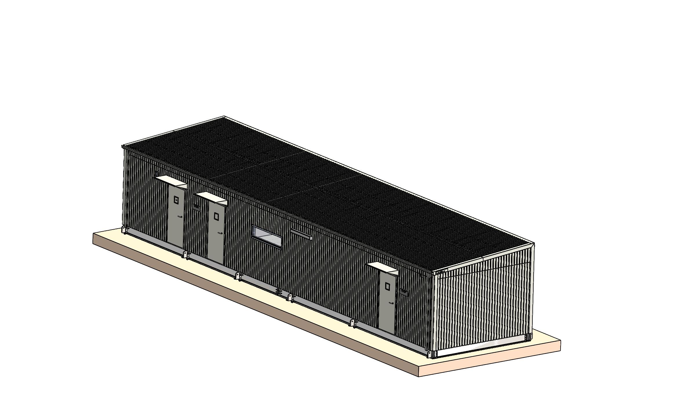
DOOR SIZE: 950mm(W) x 2200mm(H) NON-FIRE RATED DOOR WITH ROTARY LOCK.
SINGLE DOOR (INTERNAL):
DOOR SIZE: 950mm(W) x 2200mm(H) NON-FIRE RATED DOOR WITH VIEWING WINDOW
SLIDING DOOR (INTERNAL): DOOR SIZE: 1250mm(W) x 2400mm(H) NON-FIRE RATED DOOR.
SINGLE DOOR (INTERNAL):
DOOR SIZE: 820mm(W) x 1790mm(H) NON-FIRE RATED DOOR WITH ROTARY LOCK
WINDOW: WINDOW SIZE: 1800mm(W) x 400mm(H) NON-FIRE RATED
FLOORING FIBRE CEMENT SHEET 18mm CFC HEAVY DUTY 2mm VINYL, COLOUR "GREY"
ORANA BESS BESS YARD O&M BUILDING
SITE CONDITIONS / BUILDING DESIGN


FIP (FIRE INDICATOR PANEL)


Appendix C. PAVEMENT DETAILS
Orana Battery Energy Storage System (BESS)

Appendix D. TRANSFORMERS’ DATASHEETS AND FIRE WALLS
Orana Battery Energy Storage System (BESS)

Certification for BESS Step-Up Transformer (Tyree Stockcode: 4600M601)
(K) Rated Liquid Filled Transformers with Enhanced Protection for Compliance to AS2067 and equivalence to FM3990.
Tyree Transformers offer the Step Up Transformers for Orana BESS/Akaysha Energy Project fluid filled transformers that comply with the requirements of Australian Standard AS2067 and equivalent to Factory Mutual (FM) standard 3990 as follows.
- Designed to IEC60076, specifically AS60076 as required in Australia
- Transformer rectangular tanks that are designed and tested with a minimum withstand pressure of 55kPA without permanent distortion, leakage or rupture and withstand pressure of 150kPA, both of which exceed the requirements of FM3990.
- Pressure relief valves sized sufficiently to limit internal pressure under low current arcing faults to prevent tank rupture. The opening pressure of the relief device is 80kPA and the minimum flow rate is 2500Ls-1 at 100kPA minimum.
- The pressure relief valve is provided with DPDT alarm contacts to integrate directly with external electrical protection.
- Fluid filled with Cargill FR3 Envirotemp Natural Ester which comply with ASTM D92 and have a fire point greater than 300oC.
- Electrical protection of the transformer will be provided external to the transformer to limit high energy and low energy faults
- Neutral current CT for detection of earth fault currents for LV windings to integrate directly with external electrical protection devices.
- Liquid level indicator
- Liquid temperature indicator
- Pressure-vacuum gauge
- Allow a tilt angle of the tank up to 1.5degree without affecting insulation of the transformer
Tyree (K) Rated Liquid Filled Transformers with Enhanced Protection are designed and manufactured under Tyree’s ISO9001 accreditation QEC0326 in Mittagong, NSW, Australia.

SPECIFICATION
REQUIREMENT
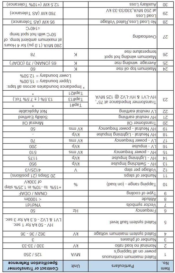
Battery Energy Storage System (BESS)
Appendix E. VBB FIRE INVESTIGATION

Orana

Victorian Big Battery Fire: July 30, 2021
REPORT OF TECHNICAL FINDINGS
ANDY BLUM, PE, CFEI
SENIOR FIRE PROTECTION ENGINEER
TOM BENSEN, PRINCIPAL FOUNDER
PAUL ROGERS, PRINCIPAL FOUNDER
CASEY GRANT, PE, SENIOR CONSULTANT
GEORGE HOUGH, SENIOR CONSULTANT
Fisher Engineering, Inc.
Background
The Victorian Big Battery (VBB) is a 300-Megawatt (MW)/450-Megawatt hour (MWh) grid-scale battery storage project in Geelong, Australia. VBB is one of the largest battery installations in the world and can power over one million Victorian homes for 30 minutes during critical peak load situations.1 It is designed to support the renewable energy industry by charging during times of excess renewable generation. The VBB is fitted with 212 Tesla Megapacks to provide the 300-MW/450-MWh of energy storage. The Megapack is a lithium-ion battery energy storage system (BESS) consisting of battery modules, power electronics, a thermal management system, and control systems all pre-manufactured within a single cabinet that is approximately 7.2 meters (m) in length, 1.6 m deep and 2.5 m in height (23.5 feet [ft] x 5.4 ft x 8.3 ft).
On Friday, July 30th, 2021, a single Megapack at VBB caught fire and spread to a neighboring Megapack during the initial installation and commissioning of the Megapacks. The fire did not spread beyond these two Megapacks and they burned themselves out over the course of approximately six hours. There were no injuries to the general public, to site personnel or to emergency first responders as the Megapacks failed safely (i.e., slowly burned themselves out with no explosions or deflagrations), as they are designed to do in the event of a fire. Per the guidance in Tesla’s Lithium-Ion Battery Emergency Response Guide2 (ERG), emergency responders permitted the Megapack to burn and consume itself while nearby exposures were being monitored at a safe distance. The total impact to the site was two out of the 212 Megapacks were fire damaged, or less than 1% of the BESS.
Following the emergency response, a detailed, multi-entity fire investigation commenced on August 3, 2021. The investigation process included local regulatory entities, Tesla, outside third-party engineers and subject matter experts. The investigation process involved analyzing both the fire origin and cause as well as the root cause of the fire propagation to the neighbor Megapack. In addition, given this is the first fire event in a Megapack installation to date, a review of the emergency response has been performed to identify any lessons learned from this fire event.
This report summarizes those investigations and analyses and has been prepared by Fisher Engineering, Inc. (FEI) and Energy Safety Response Group (ESRG), two independent engineering and energy storage fire safety consulting firms. In addition, this report provides a list of lessons learned from the fire and also highlights the procedural, software and hardware changes that have been implemented based on those lessons learned.
Incident Timeline
At the time of the fire, the VBB was fitted with approximately one-half of the 212 total Megapacks intended for the site. The Megapacks that were installed at VBB were undergoing routine testing and commissioning on the day of the fire. At 7:20 AM Australian Eastern Standard Time (AEST) on the morning of July 30, 2021, commissioning and testing of a number of Megapacks commenced. One such Megapack (denoted herein as MP-1), was not going to be tested that day and was therefore shut off manually by means of the keylock switch.3 At the time MP-1 was shut down via the keylock switch, the unit displayed no abnormal conditions to site personnel. Around 10:00 AM, smoke was observed emitting from MP-1 by site personnel. Site personnel
1 https://victorianbigbattery.com.au/
2 https://www.tesla.com/sites/default/files/downloads/Lithium-Ion_Battery_Emergency_Response_Guide_en.pdf
3 The keylock switch is a type of “lock out tag out” switch onthefrontoftheMegapackthatsafelypowersdowntheunit forservicing.
electrically isolated all the Megapacks on-site and called emergency services: Country Fire Authority (CFA). The CFA arrived shortly thereafter and set up a 25 m (82 ft) perimeter around MP-1. They also began applying cooling water to nearby exposures as recommended in Tesla’s ERG. The fire eventually spread into a neighbor Megapack (MP-2) installed 15 centimeters (cm), or 6 inches (in), behind MP-1. The CFA permitted MP-1 and MP-2 to burn themselves out and did not directly apply water into or onto either Megapack, as recommended in Tesla’s ERG. By 4:00 PM (approximately six hours after the start of the event), visible fire had subdued and a fire watch was instituted. The CFA monitored the site for the next three days before deeming it under control on August 2, 2021, at which time, the CFA handed the site over for the fire investigation to begin.
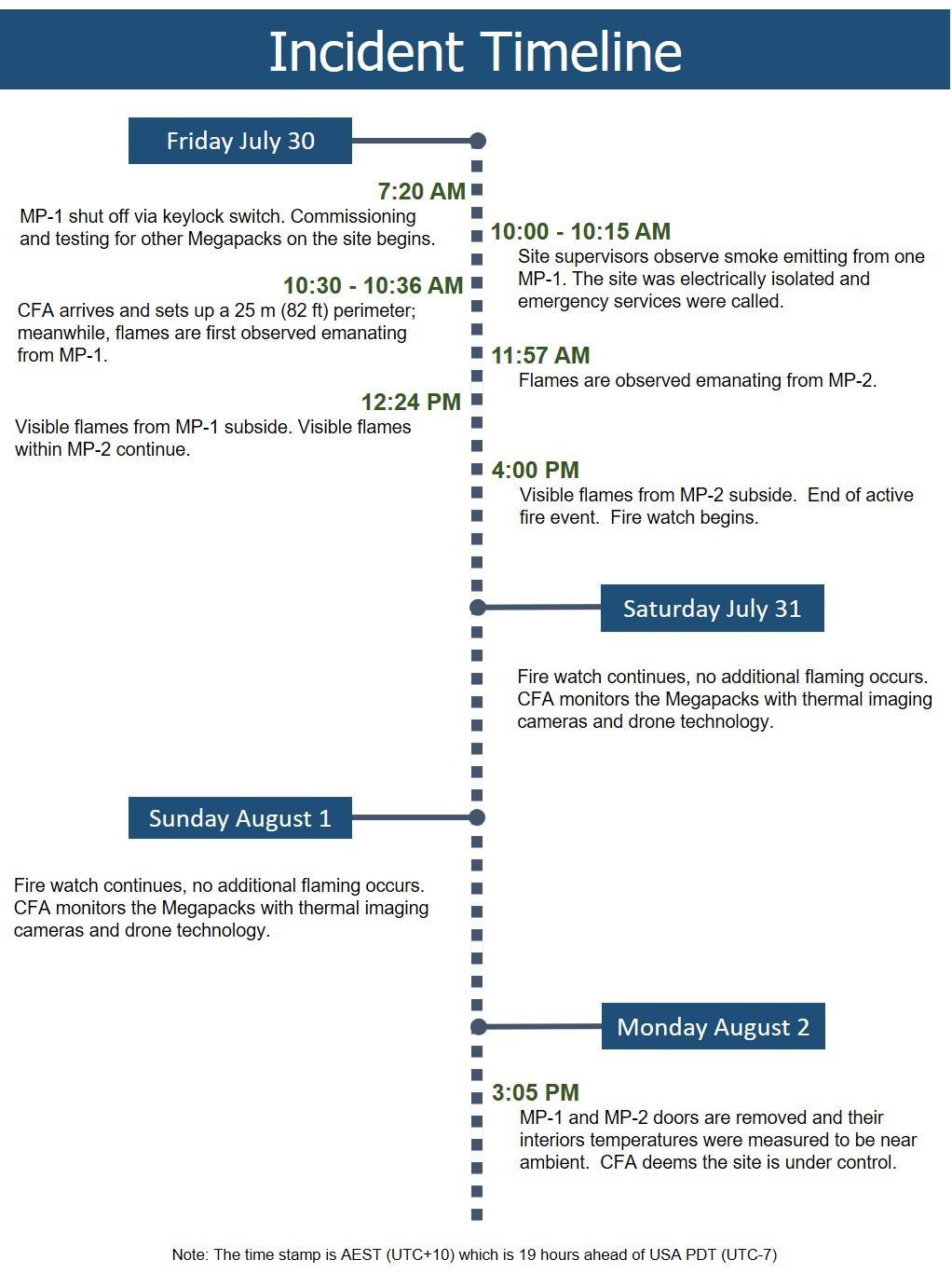
Investigation
A multi-entity fire investigation commenced on August 3, 2021. The VBB fire investigation process involved analyzing both the root cause of the initial fire in MP-1 as well as the root cause of the fire propagation into MP-2. The investigations included on-site inspections of MP-1 and MP-2 by the CFA, Energy Safe Victoria4 (ESV), Work Safety Victoria5 (WSV), local Tesla engineering/service teams and a local third-party independent engineering firm. In addition to the on-site work immediately after the incident, the root cause investigations also included data analysis, thermal modeling and physical testing (electrical and fire) performed by Tesla at their headquarters in California, USA and their fire test facility in Nevada, USA.
Fire Cause Investigation
On-site inspections commenced on August 3, 2021 and concluded on August 12, 2021. MP-1 and MP-2 were documented, inspected and preserved for future examinations, if necessary. Concurrently, all available telemetry data (such as internal temperatures and fault alarms) from MP-1 and MP-2 were analyzed and a series of electrical fault and fire tests were performed. The on-site investigation findings, the telemetry data analysis, electrical fault tests and fire tests, when combined, identified a very specific series of fault conditions present on July 30, 2021 that could lead to a fire event.
Fire Origin and Cause Determination
The origin of the fire was MP-1 and the most likely root cause of the fire was a leak within the liquid cooling system of MP-1 causing arcing in the power electronics of the Megapack’s battery modules. This resulted in heating of the battery module’s lithium-ion cells that led to a propagating thermal runaway event and the fire.
Other possible fire causes were considered during the fire cause investigation; however, the above sequence of events was the only fire cause scenario that fits all the evidence collected and analyzed to date.
Contributory Factors
A number of factors contributed to this incident. Had these contributory factors not been present, the initial fault condition would likely have been identified and interrupted (either manually or automatically) before it escalated into a fire event. These contributory factors include:
1. The supervisory control and data acquisition (SCADA) system for a Megapack required 24 hours to setup a connection for new equipment (i.e., a new Megapack) to provide full telemetry data functionality and remote monitoring by Tesla operators. Since VBB was still in the installation and commissioning phase of the project (i.e., not in operation), MP-1 had only been in service for 13 hours prior to being switched off via the keylock switch on the morning of the fire. As such, MP-1 had not been on-line for the required 24 hours, which prevented this unit from transmitting telemetry data (internal temperatures, fault alarms, etc.) to Tesla’s off-site control facility on the morning of the fire.
2. The keylock switch for MP-1 was operated correctly on the morning of the fire to turn MP-1 off as the unit was not required for commissioning and testing that morning; however, this action caused telemetry systems, fault monitoring, and electrical fault safety devices6 to be disabled or operate with
4 Victoria’s energy safety regulator
5 Victoria’s health and safety regulator
6 Theseelementsinclude,amongotherdevices,fusesatthecellandmodulelevelforlocalizedfaultcurrentinterruption andabatterymodulepyrodisconnectthatseverstheelectricalconnectionofthebatterymodulewhenafaultcurrent ispassingthroughthebatterymodule.
only limited functionality. This prevented some of the safety features of MP-1 from actively monitoring and interrupting the electrical fault conditions before escalating into a fire event
3. The exposure of liquid coolant onto the battery modules likely disabled the power supply to the circuit that actuates the pyro disconnect.7 With a power supply failure, the pyro disconnect would not receive a signal to sever and would not be able to interrupt a fault current passing through the battery module prior to it escalating into a fire event.
Fire Propagation Investigation
The VBB fire investigation process involved analyzing not only the root cause of the initial fire in MP-1 but also the root cause of the fire propagation into MP-2. The Megapack has been designed to be installed in close proximity to each other without fire propagating to adjacent units. The design objective of the Megapack in terms of limiting fire propagation was mainly reliant on the thermal insulation of the Megapack’s exterior vertical steel panels and the sheer mass of the battery modules acting as a heat sink (i.e., they are difficult to heat up). With this thermal insulation, the Megapack spacing can be as close as 15 cm (6 in) to the sides and back of each unit with 2.4 m (8 ft) aisles in front of each Megapack, as shown in Figure 1. This product spacing has been validated in UL9540A unit level tests.8 Similar to the fire origin and cause investigation, the on-site inspections were supported simultaneously with an analysis of telemetry data (such as internal temperatures) from MP-2 and fire testing. The on-site investigation findings, the telemetry data analysis and fire tests, when combined, identified a scenario where Megapack to Megapack fire propagation can occur.
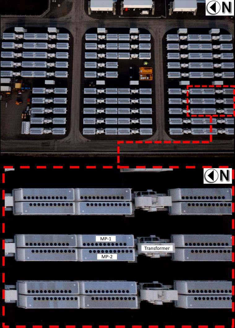
7 ThepyrodisconnectisaTeslaproprietaryshunt-controlledpyrotechnicfusethatallowsforrapidone-timeactuation. Thereisonepyrodisconnectperbatterymodule.
8 UL9540A, Test Method for Evaluating Thermal Runaway Fire Propagation in Battery Energy Storage Systems. UL9540A isatestmethoddevelopedbyULtoaddressfiresafetyconcernswithBESS. Thetestmethodprovidesamethodto evaluatethermalrunawayandfirepropagationatthecelllevel,modulelevel,andunitlevel. Inadditiontocelland moduleleveltests,Teslaperformedunitlevelteststoevaluate,amongotherfiresafetycharacteristics,thepotentialfor fire propagation from Megapack-to-Megapack. During unit level testing, fire propagation did not occur between Megapackswhentheywereinstalledwithaspacingof15cm(6in)tothesidesandbackofeachunit.
Figure 1 VBB Megapack layout (top) and area of fire origin (bottom)
Fire Propagation Determination
Flames exiting the roof of MP-1 were significantly impacted by the wind conditions at the time of the fire. Wind speeds were recorded between 20-30 knots9 which pushed the flames exiting the roof of MP-1 towards the roof of MP-2. This direct flame impingement on the top of the thermal roof of MP-2 ignited the internal components of MP-2, most notably, the plastic overpressure vents that seal the battery bay10 from the thermal roof. Once ignited, the overpressure vents provided a direct path for flames and hot gases to enter into the battery bays, thus exposing the battery modules of MP-2 to fire and/or elevated temperatures. Exposed to temperatures above their thermal runaway threshold of 139°C (282°F), the cells within the battery modules eventually failed and became involved in the fire.
Other possible fire propagation root causes were considered during the investigation; however, the above sequence of events was the only fire propagation scenario that fits all the evidence collected and analyzed to date. Of note, at the time when fire was observed within the thermal roof of MP-2, internal cell temperature readings of MP-2 had only increased by 1°C (1.8°F) from 40°C to 41°C (104°F to 105.8°F)11 Around the same time that fire was observed within the thermal roof of MP-2, around 11:57 AM (approximately 2 hours into the fire event), communication was lost to the unit and no additional telemetry data was transmitted. However, given the internal cell temperatures of MP-2 had only recorded a 1°C (1.8°F) temperature rise 2 hours into the fire event and while the unit’s roof was actively on fire, fire propagation across the 15 cm (6 in) gap via heat transfer is not the root cause of the fire propagation. Furthermore, this telemetry data from MP-2 demonstrates that the Megapack’s thermal insulation can provide significant thermal protection in the event of a fire within an adjacent Megapack installed only 15 cm (6 in) away.
Contributory Factors
The wind was the dominant contributory factor in the propagation of fire from MP-1 to MP-2. At the time of the fire, a 20-30 knot (37-56 km/hr, 23-35 mph) wind was recorded out of the north. The wind conditions at the time of the fire pushed the flames exiting out of the top of MP-1 towards the top of MP-2 leading to direct flame impingement on the thermal roof of MP-2. This type of flame behavior was not observed during previous product testing or regulatory testing per UL9540A. In UL9540A unit level testing, the maximum wind speed permitted12 during the test is 10.4 knots (19.3 km/hr, 12.0 mph); whereas, wind conditions during the VBB fire were two to three times greater in magnitude. As such, the wind conditions during the VBB fire appear to have identified a weakness in the Megapack’s thermal roof design (unprotected, plastic overpressure vents in the ceiling of the battery bays) that allows Megapack-to-Megapack fire propagation. This weakness was not identified previously during product or regulatory testing and does not invalidate the Megapack’s UL9540A certification, as the cause of fire propagation was primarily due to an environmental condition (wind) that is not captured in the UL9540A test method.
9 Thisequatesto37-56kilometersperhour(km/hr)or23-35milesperhour(mph).
10 ThebatterybayisanIP66enclosurethathousesthebatterymodules. Itisdistinctfromthethermalroofinstalledabove it.Plasticoverpressureventsareinstalledintheceilingofthebatterybay,sealingthetwoenclosuresfromoneanother.
11 As a reference, the Megapack’s normal operating cell temperature is between20-50°Candcellthermalrunawaydoes notoccuruntil139°C(98°CabovecelltemperaturesofMP-2beforetelemetrydatawaslost).
12 Thisthresholdisnecessaryfortestreliabilityandreproducibility. Ifwindconditionsarenotboundedinsomefashionin anoutdoorfiretest,largevariancesonproductperformancecouldbeintroducedduetovaryingwindconditions.
Mitigations
The investigation of the VBB fire identified several gaps in Tesla’s commissioning procedures, electrical fault protection devices and thermal roof design. Since the fire, Tesla has implemented a number of procedural, firmware, and hardware mitigations to address these gaps. These mitigations have been applied to all existing and any future Megapack installations and include:
Procedural Mitigations:
• Improved inspection of the coolant system for leaks during Megapack assembly and during end-of-line testing to reduce the likelihood of future coolant leaks.
• Reduce the telemetry setup connection time for new Megapacks from 24 hours to 1 hour to ensure new equipment is transmitting telemetry data (internal temperatures, fault alarms, etc.) to Tesla’s offsite control facility for remote monitoring.
• Avoid utilizing the Megapack’s keylock switch during commissioning or operation unless the unit is actively being serviced. This procedural mitigation ensures telemetry, fault monitoring, and electrical fault safety devices (such as the pyro disconnect) are active while the Megapack is idle (such as during testing and commissioning).
Firmware Mitigations:
• Added additional alarms to the coolant system’s telemetry data to identify and respond (either manually or automatically) to a possible coolant leak.
• Keep all electrical safety protection devices active, regardless of keylock switch position or system state. This firmware mitigation allows electrical safety protection devices (such as the pyro disconnect) to remain in an active mode, capable of actuating when electrical faults occur at the battery modules, no matter what the system status is.
• Active monitoring and control of the pyro disconnect’s power supply circuit. In the event of a power supply failure (either through an external event such as a coolant exposure or some other means), the Megapack will automatically actuate the pyro disconnect prior to the loss of its power supply.
Hardware Mitigations
• Installation of newly designed, thermally insulated steel vent shields within the thermal roof of all Megapacks. These vent shields protect the plastic overpressure vents from direct flame impingement or hot gas intrusion, thus keeping the IP66 battery bay enclosures isolated from a fire above in the thermal roof. Their performance was validated through a series of fire tests, including unit level fire testing of entire Megapack units.13 The vent shields are placed over the top of the overpressure vents and will come standard on all new Megapack installations. For existing Megapacks, the vent shields can be installed in the field (retrofit) with minimal effort or disruption to the unit. At the time of this report, the vent shields are nearing production stage and will be retrofitted to applicable Megapack sites shortly.
13 Thetestsconfirmedthat,evenwiththeentirethermalrooffullyinvolvedinfire,theoverpressureventswillnotignite andthebatterymodulesbelowremainrelativelyunaffectedbythefireabove. Forinstance,thecellswithinthebattery modulessawalessthan1°Ctemperaturerisewhiletheentirethermalroofwasfullyinvolvedinfire.
Emergency Response
Beyond the origin and cause and propagation investigations, another key aspect of the VBB fire was the emergency response. The CFA is the responsible fire service organization for VBB, and the facility is in their initial response jurisdiction. The location of the VBB facility is in a semi-rural location. The nearest fire station is the CFA Lovely Banks, approximately 4 km (2.5 miles) distance from VBB and thus relatively close, though other resources had more extended travel distances.
Upon arrival around 10:30 AM, CFA immediately established incident command (IC) in accordance with their protocols, and the IC worked closely with the facility representatives and subject matter experts (SMEs). This close coordination continued throughout the entire event. The facility was evacuated and all-site personnel accounted-for upon notification of the emergency event and the commencement of fire service operations. A 25 m (82 ft) perimeter was established around MP-1 while water application and cooling strategies were discussed with facility representatives and subject matter experts (SMEs). The decision was made to provide exposure protection to Megapacks and transformers adjacent to MP-1 and MP-2 using water hose lines, as recommended in Tesla’s ERG. The fire eventually propagated into MP-2; however, flame spread did not advance any further than MP-1 and MP-2. The two Megapacks were permitted to burn themselves out, during which time the CFA did not directly apply water into or onto either Megapack. By 4:00 PM (approximately six hours after the start of the event), visible flames had subdued and a fire watch was instituted. The CFA continued to monitor the site for the next three days before deeming it under control on August 2, 2021, at which time, the fire investigation began.
Key Takeaways
A thorough review of the VBB fire emergency response yielded the following key takeaways:
• Effective Pre-incident Planning: VBB had both an Emergency Action Plan (EAP) and an Emergency Response Plan (ERP). Both plans were available to emergency responders and were effectively used during the VBB fire. For example, all site employees and contractors followed proper evacuation protocols during the fire and as a result, no injuries occurred to those personnel.
• Coordination with SMEs: VBB had thorough pre-incident plans that clearly identified the SMEs, how to contact them, their role and other key tasks. It was reported that the facility SMEs stayed in close contact with the CFA IC throughout the VBB fire, providing valuable information and expertise for the CFA to draw upon. For example, site representatives and SMEs worked closely with the CFA in determining water application and cooling strategies of adjacent exposures.
• Water Application: A key question regarding water application is the necessary amount and duration for effective fire containment. Tesla’s design philosophy is based on inherent passive protection (i.e., thermal insulation), with minimal dependence on active firefighting measures like external hose lines. As such, water was not aimed at suppressing the fire but rather protecting the exposures as directed by Tesla’s ERG and the SMEs on site. All available data and visual observations of the fire indicates water had limited effectiveness in terms of reducing or stopping fire propagation from Megapack-toMegapack. The thermal insulation appears to be the dominant factor in reducing heat transfer between adjacent Megapacks. However, water was effectively used on other exposures
(transformers, electrical equipment, etc.) to protect that equipment, which are not designed with the same level of protection as a Megapack is (i.e., thermal insulation).14
• The fire protection design approach of the Megapack has inherent advantages over other BESS designs in terms of safety to emergency responders. The Megapack approach minimizes the likelihood of fire spread using passive compartmentation and separation, eliminates the danger to fire fighters of an overpressure event due to design features and a lack of confinement (e.g., outdoor versus indoor), does not rely on active firefighting measures like external hose lines and minimizes the dangers from stranded electrical energy to those involved with overhaul and de-commissioning with a fire response approach permitting the Megapack to burn itself out.
Environmental Concerns
The Environment Protection Authority Victoria (EPA) deployed two mobile air quality monitors within 2 km (1.2 miles) of the VBB site. Locations were chosen where there was potential to impact the local community. The EPA monitors confirmed “good air quality in the local community” after the incident; however, the measurements were not taken during the peak of the fire event. They were sampled around 6:00 PM, or approximately 2 hours after the fire was out. Therefore, the data cannot be used to understand the airborne hazards during the actual fire event. The data does demonstrate that two hours after the fire event, the air quality in the surrounding area was “good” and no long-lasting air quality concerns arose from the fire event.15
During the fire event, the CFA coordinated with site personnel to control the water run-off from fire hoses into a catchment. Water samples, collected by Tesla site personnel under the supervision of CFA, were extracted from the catchment. Laboratory results from those samples indicated that the likelihood of the fire having a material impact on the water was minimal. After the incident, as a precaution, the water was removed from the catchment, via suction trucks, and was transported to a licensed waste facility for treatment and disposal. It is estimated that approximately 900,000 liters of water was disposed of from the site after the event.
Community Concerns
Neoen, the project developer and owner, pro-actively engaged with the local community during and following the VBB fire These engagements included door-to-door visits, phone calls and emails with the residential and agricultural properties within a 2-3 km (1.2-1.9 mile) radius of the VBB site. Neoen found their prior community outreach during the project planning stages to be invaluable as this outreach provided up-to-date contact information for Neoen when reaching out to the local community during and following the fire. In addition, Neoen formed an executive stakeholder steering committee compromising of key organizations within 24 hours of the incident. With multiple parties involved in the emergency response to the fire event
14 Atthetimeofthisreport,finalfiredepartmentreportswerenotavailableforreviewandinclusion. Asthatinformation becomesavailable,additionalinformationregardingwaterusageandeffectivenessmayrequireinclusioninthisreport. AlthoughtheeffectivenessofexternalwaterinaMegapackfiremaybelimited,watershouldstillbemadeavailablefor exposure protection and other unanticipated events in the future, as required by any applicable regulatory requirements.
15 Itshouldbenotedthatpriorregulatorytesting(UL9540Amodulelevelfiretesting)hasshownthattheproductsof combustionofaMegapackbatterymodulecanincludeflammableandnonflammablegases. Basedonthoseregulatory tests,theflammablegaseswerefoundtobebelowtheirlowerflammablelimit(LFL)andwouldnotposeadeflagration orexplosionrisktofirstrespondersorthegeneralpublic. Thenonflammablegaseswerefoundtobecomparabletothe smokeyouwouldencounterinatypicalClassAstructurefireanddonotcontainanyunique,oratypical,gasesbeyond whatyouwouldfindinthecombustionofmoderncombustiblematerials.
actively participating in the steering committee, this helped ensure that from the outset communication was timely, efficient, well-coordinated across different organizations and accurate.
In addition to the community outreach, Neoen and Tesla also briefed multiple industry, State and Federal Government Departments and Agencies immediately following the VBB fire and at the conclusion of the investigation process. These briefings helped ensure the wider energy sector with interests in BESS were able to be kept directly informed as information became available.
Overhaul and Remediation
On July 29, 2021 nearly half of the Megapacks had been installed and the site was in the testing and commissioning stage of the project. Following the fire event on July 30, 2021, fire department personnel, regulatory agencies and other emergency responders remained on-site for precautionary purposes until August 2, 2021. At that time the site was turned over for regulatory fire investigations to begin. On-site fire investigations started on August 3, 2021 and continued until August 12, 2021. During this time, starting on August 6, 2021, the site was permitted to continue the installation of Megapacks while the area around MP-1 remained cordoned off for the investigation. On September 23rd, 2021, less than two months after the fire, VBB was re-energized and testing and commissioning restarted. Remediation of the damaged equipment followed shortly after, and lasted a total of three days. All testing and commissioning efforts were completed without any further incidents and on December 8, 2021, VBB officially opened.
Lessons Learned
The VBB fire exposed a number of unlikely factors that, when combined, contributed to the fire initiation as well as its propagation to a neighboring unit. This collection of factors had never before been encountered during previous Megapack installations, operation and/or regulatory product testing. This section summarizes those factors as well as the emergency response to the fire, discusses the lessons learned from this fire event, and highlights the mitigations Tesla has implemented in response.
1. Commissioning Procedures
Lessons learned related to commissioning procedures include: (1) limited supervision/monitoring of telemetry data during the first 24 hours of commissioning and (2) the use of the keylock switch during commissioning and testing. These two factors prevented MP-1 from transmitting telemetry data (internal temperatures, fault alarms, etc.) to Tesla’s control facility and placed critical electrical fault safety devices (such as the pyro disconnect) in a state of limited functionality, reducing the Megapack’s ability to actively monitor and interrupt electrical fault conditions prior to them escalating into a fire event.
Since the VBB fire, Tesla has modified their commissioning procedures to reduce the telemetry setup connection time for new Megapacks from 24 hours to 1 hour and to avoid utilizing the Megapack’s keylock switch unless the unit is actively being serviced.
2. Electrical Fault Protection Devices
Lessons learned related to electrical fault protection devices include: (1) coolant leak alarms; (2) the pyro disconnect being unable to interrupt fault currents when the Megapack is off via the keylock switch and (3) the pyro disconnect likely being disabled due to a power supply loss to the circuit that actuates it. These three factors prevented the pyro disconnect of MP-1 from actively monitoring and interrupting the electrical fault conditions before escalating into a fire event.
Since the VBB fire, Tesla has implemented a number of firmware mitigations that keep all electrical safety protection devices active, regardless of keylock switch position or system state, and to actively monitor and control the pyro disconnect’s power supply circuit. Furthermore, Tesla has added additional alarms to better identify and respond (either manually or automatically) to coolant leaks. Additionally, although this fire event was likely initiated by a coolant leak, unexpected failures of other internal components of the Megapack could create similar damage to the battery modules. These new firmware mitigations do not only address damage from a coolant leak. They also permit the Megapack to better identify, respond, contain and isolate issues within the battery modules due to failures of other internal components, should they occur in the future.
3. Fire Propagation
Lessons learned related to fire propagation include: (1) the significant role external, environmental conditions (such as wind) can have on a Megapack fire and (2) the identification of a weakness in the thermal roof design that permits Megapack-to-Megapack fire propagation. These two factors led to direct flame impingement on the plastic overpressure vents that seal the battery bay from the thermal roof. With a direct path for flames and hot gases to enter into the battery bays, the cells within the battery modules of MP-2 failed and became involved in the fire.
Since the VBB fire, Tesla has devised (and validated through extensive testing) a hardware mitigation that protects the overpressure vents from direct flame impingement or hot gas intrusion via the installation of new, thermally insulated, steel vent shields. The vent shields are placed on top of the overpressure vents and will come standard on all new Megapack installations. For existing Megapacks, the vent shields can be easily installed in the field. At the time of this report, the vent shields are nearing production stage and will be retrofitted to applicable Megapack sites shortly.
4. Megapack Spacing
Lessons learned related to Megapack spacing include: no changes are required to the installation practices of the Megapack with the vent shield mitigation (as described above) in place. Based on an analysis of telemetry data within MP-2 during the VBB fire, the Megapack’s thermal insulation can provide significant thermal protection in the event of a fire within an adjacent Megapack installed 15 cm (6 in) away. The internal cell temperatures of MP-2 only increased by 1°C (1.8°F), from 40°C to 41°C (104°F to 105.8°F), before communication was lost to the unit, presumably due to fire, around 11:57 AM (approximately 2 hours into the fire event). Fire propagation was triggered by the weakness in the thermal roof, as described above in #3, and not due to heat transfer via the 15 cm (6 in) gap between Megapacks. With the vent shield mitigation in place, the weakness has been addressed and validated through unit level fire testing (i.e., tests involving the ignition of the Megapack’s thermal roof). These tests confirmed that, even with the thermal roof fully involved in a fire, the overpressure vents will not ignite and the battery modules remain relatively unaffected with internal cell temperatures rising less than 1°C.
5. Emergency Response
Lessons learned from the emergency response to the VBB fire include: (1) effective pre-incident planning is invaluable and can reduce the likelihood of injuries; (2) coordination with SMEs, either on site or remotely, can provide critical expertise and system information for emergency responders to draw upon; (3) the effectiveness of applying water directly to adjacent Megapacks appears to provide limited benefits; however, water application to other electrical equipment, with inherently less fire protection built into their designs (such as transformers), can be a useful tactic to protect that equipment; (4) the fire protection design
approach of the Megapack has inherent advantages over other BESS designs in terms of safety to emergency responders; (5) the EPA indicated that there was “good” air quality 2 hours after the fire demonstrating that no long-lasting air quality concerns arose from the fire event; (6) water samples indicated that the likelihood of the fire having a material impact on firefighting water was minimal; (7) prior community engagement during the project planning stages is invaluable as it enabled Neoen to quickly update the local community and address immediate questions and concerns; (8) early, factual and where possible, face-to-face engagement with the local community is essential when a fire event is unfolding to keep the general public informed; (9) an executive stakeholder steering committee from the key organizations involved in the emergency response can help ensure that any pubic communications are timely, efficient, coordinated and accurate; and (10) effective coordination between stakeholders at the site allowed for rapid and thorough handover process after the incident, the swift and safe decommissioning of the damaged units and the site’s quick return to service.
In summary, the VBB fire event proceeded in accordance with its fire protection design and pre-incident planning. It presented no unusual, unexpected, or surprising characteristics (i.e., explosions) or resulted in any injuries to site personnel, the general public or emergency responders. It was isolated to the units directly involved, had minimal environmental impact, did not adversely impact the electrical grid, and had appreciably short mission interruption.
Battery Energy Storage System (BESS)
Appendix F. CFD/

ZONE MODELLING FORMS FOR HV TRANSFORMER AND HF LEAK
Orana
CFD/zone modelling inputs form
Complete this form and submit with the corresponding application form when computational fluid dynamics (CFD) or zone modelling is being undertaken as the verification method for any assessment criteria
1 Premises
Premises name (if applicable) Orana BESS
Primary street address Dubbo Region at New South Wales (NSW) 2820
Premises suburb Wellington
2 Model/program details
Type of modelling CFD modelling
Name of program FDS
Version FDS 6.10.1
Provide any other relevant details
3 General/domain parameters
3.1 CFD modelling only
Number of meshes 2
Type of mesh (e g cartesian) Cartesian
Mesh size 0.5m
Material properties
Mineral oil: C=4.00, N=0.00, H=10.00, HEAT_OF_COMBUSTION=4.605 x10⁷O=0.00, SOOT_YIELD=0.0600 gr/gr.
Boundary conditions All open. It is a pool fire located outdoors as the transformer.
Major geometrical or other simplifications or assumptions
Pool fire with the size of the transformer bund from the BESS layout.
Steady-state or transient? Steady state
Simulation time 1,800 seconds
3.2 Zone modelling only
Total floor area volume NA
Floor area and volume of each compartment NA
Openings between compartments NA
Material properties NA
Boundary conditions NA
Major geometrical or other simplifications or assumptions NA
Simulation time NA
4 Fire parameters
Radiative fraction 0.35
Reaction/combustion properties (material, heat of combustion)
Mineral oil: C=4.00, N=0.00, H=10.00, HEAT_OF_COMBUSTION=4.605 x10⁷O=0.00, SOOT_YIELD=0.0600 gr/gr.
Soot yield (value and means of including in model) 0.06
Visibility factor (or parameters used to obtain visibility output) NA
Heat release rate per unit area (HRRPUA) 1,1120kW/m2
Means of achieving fire growth rate (ramp, multiple fire objects) It is assumed the fire occurs; hence fire is instant in the simulation to assess the heat flux received from adjoining equipment
Fire locations (including height above floor) HV transformer.
5 Scenario parameters
Ambient temperature 30.9C
Wind No wind, and wind of 5.0m/s
Others Relative humidity – 58%.
6 Fire safety system/device parameters
Mechanical smoke exhaust NA
Mechanical supply air NA
Jet fans NA
Natural vents NA
Natural make-up air NA, all mesh is open.
Assumed building leakage NA
Sprinklers (spacing, location, RTI, distance to fire, rating etc.) Na
Detectors (spacing, location, RTI, distance to fire, rating, activation obscuration etc.) NA
Other systems/devices NA
7 Outputs
Actual heat release rate curve produced should be compared to specified design fire
Sufficient outputs should be provided to justify any results used in the ASR
No curve obtained; it is an instant fire to assess heat flux in adjoining equipment. The transformer fire treated as a pool fire is based on liquid hydrocarbon fire.
Heat flux at different distances as per the Layout of Orana BESS. Heat flux results shown in the FSS Section 7.

CFD/zone modelling inputs form
Complete this form and submit with the corresponding application form when computational fluid dynamics (CFD) or zone modelling is being undertaken as the verification method for any assessment criteria
1 Premises
Premises name (if applicable) Orana BESS
Primary street address Dubbo Region at New South Wales (NSW) 2820
Premises suburb Wellington
2 Model/program details
Type of modelling CFD modelling
Name of program FDS
Version FDS 6.10.1
Provide any other relevant details
3 General/domain parameters
3.1 CFD modelling only
Number of meshes 2
Type of mesh (e g cartesian) Cartesian
Mesh size 1.0m
Material properties HF: 4.69854 x 10^-6 kg/m2-s from 12 modules. Gas temperatures of 31.2C and 300C.
Boundary conditions All open. The BESS unit is outdoors
Major geometrical or other simplifications or assumptions The Megapack 2XL supplies the quantities of toxic gases measured in the tests. Instant reactions.
Steady-state or transient? Steady state
Simulation time 1,800 seconds
3.2 Zone modelling only
Total
4 Fire parameters
Radiative fraction
Reaction/combustion properties (material, heat of combustion)
Soot yield (value and means of including in model)
Visibility factor (or parameters used to obtain visibility output)
Heat release rate per unit area (HRRPUA)
Means of achieving fire growth rate (ramp, multiple fire objects)
Fire locations (including height above floor)
5 Scenario parameters
6 Fire safety system/device parameters
(spacing, location, RTI, distance to fire, rating, activation obscuration etc.)
systems/devices
BESS Megapack 2XL.
7 Outputs
Actual heat release rate curve produced should be compared to specified design fire NA
Sufficient outputs should be provided to justify any results used in the ASR
Others
The objective is to quantify the toxicity quantities of HF around the BESS which incurs in Thermal runaway.
Orana Battery Energy Storage System (BESS)

Attachment issued in a separated file.
Orana Battery Energy Storage System (BESS)

Appendix H. FIRE PROTECTION ENGINEERING ANALYSIS (FISHER ENGINEERING)
Attachment issued in a separated file.
Battery Energy Storage System (BESS)
Appendix I. DETAILED DRAWINGS OF FIRE SERVICES LAYOUT

Orana


Appendix J. EROSION AND SEDIMENT CONTROL PLAN
Orana Battery Energy Storage System (BESS)


Appendix K. AKAYSHA ENERGY PTY LTD. AGREEMENT
Orana Battery Energy Storage System (BESS)
