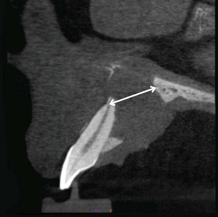
Imaging artifact from facial piercing fenestration
PHARMACOLOGY
Managing anticoagulant medications
IMPLANTS
Hybrid-resolution facial and dental scanning
AGD HAS BENEFITS FOR YOUR UNIQUE NEEDS
BEFORE YOUR NEXT BIG PURCHASE, CHECK MEMBERS-ONLY DISCOUNTS ON PRODUCTS AND SERVICES agd.org/exclusive-benefits
ASSOCIATE DENTIST
PRACTICE OWNER
FELLOW/MASTER
AGD LEADER
• 4 Imprint
• AccountingDepartment.com
• ADP
• AGDVANTAGE
• All-Star Dental Academy
• Avis and Budget
• CareCredit
• Dental Card Services Alliance
• Dentist’s Advantage
• Hagan Insurance Group
• Liberty Mutual Insurance
• MemberDeals
• Naylor Association Solutions
• Office Depot
• SoFi
STUDENT/RESIDENT
• Avis and Budget
• Dentist’s Advantage
• Hagan Insurance Group
• Liberty Mutual Insurance
• MemberDeals
• Naylor Association Solutions
• Office Depot
• SoFi
A Call for Columnists
Make an impression on your profession
General Dentistry is seeking new columnists. If you are a strong writer with an idea for a new column, keep reading…
Our columnists write succinct overviews of specific cases or issues within a subject area two to four times per year, providing general dentists with information that they can use in practice right away. While scientific accuracy is a must, columns can be written in a less formal style than our clinical articles.
But what can writing a column do for you?
It gives you the opportunity to enlighten readers with your in-depth knowledge, share lessons learned from unique or challenging cases, and inform both new and seasoned dentists about advances within your area of expertise.
Become a trusted voice for our readers. Contact us with your column idea today.
Email us at general.dentistry@agd.org.
DEPARTMENTS
5 Editorial
Go, slow, or stop: obeying the signs
6 Pharmacology
Managing anticoagulant medications around dentistry
78
Oral Diagnosis
Ragged bony destruction and Expansile mass of mixed density
79
Self-Instruction Answers
Exercises No. GD515, GD516, and GD517
CLINICAL ARTICLES
10 Endodontics
Nonsurgical management of large periapical lesions: case reports and review of the literature
Shubham Tripathi
Pradeep Jain
Sanket Hans Pandey
SELF-INSTRUCTION
20 Periodontics
Pallav Patni
Swadhin Raghuwanshi
Treatment of deep gingival recession in homologous molars using a modified laterally positioned flap and subepithelial connective tissue graft: a case report
Maria Caroline Rios Piecha
Tiago Schlindvein de Araujo
Rodrigo Könsgen Rossales
Thiago Marchi Martins
SELF-INSTRUCTION EXERCISE GD534, 2 CE CREDITS, P. 26
27 Pediatric Dentistry
Multidisciplinary approach to multiple dental anomalies in pediatric patients: a case report with 4-year follow-up
Florense Gabriela da Silva
Mayara Rangel
Tatiane Fernandes Novaes
Renata Oliveira Guaré
31 Implants
Priscila Hernández de Campos
Cássio José Fornazari Alencar
Michele Baffi Diniz
Hybrid-resolution facial and dental scanning: a cost-effective approach to utilizing 3D facial data in anterior dental implant restoration
Adam P. Tow
38 Basic Science
Effect of mouthwashes on the color stability of a nanohybrid composite resin
Giovanna Pinto Wallace da Silva
Danielson Guedes Pontes
SELF-INSTRUCTION
Vitória Uchôa Mesquita
43 Implants
A new guide for enhancing dental implant placement: an in vitro assessment of accuracy
Members, call 888.243.3368 and ask for a Member Services representative.
Mailing Lists
For information about ordering AGD mailing lists, call 888.243.3368 ext. 4097 or email advertising@agd.org.
All materials subject to copying and appearing in General Dentistry may be photocopied for the noncommercial purposes of scientific or educational advancement. Reproduction of any portion of General Dentistry for commercial purposes is strictly prohibited unless the publisher’s written permission is obtained.
AGD does not necessarily endorse opinions or statements contained in essays or editorials published in General Dentistry. The publication of advertisements in General Dentistry does not indicate endorsement for products and services. AGD approval for continuing education courses or course sponsors will be clearly stated.
General Dentistry (ISSN 0363-6771) is published bimonthly in 2024 by the AGD, 560 W Lake St, Sixth Floor, Chicago, IL 60661-6600. AGD members receive GeneralDentistry as part of membership.
Periodicals postage paid at Chicago, IL and additional mailing office. POSTMASTER: Send address changes to General Dentistry, 560 W Lake St, Sixth Floor, Chicago, IL 60661-6600. Email: subscriptions@agd.org.
Canadian mailing information: IPM Agreement number 40047941. Change of address or undeliverable copies should be sent to: Station A, PO Box 54, Windsor, Ontario, N9A 6J5, Canada. Email: subscriptions@agd.org.
The nonmember individual subscription rate for General Dentistry is $120 for the print version, $120 for the online version, and $200 for print and online versions; the nonmember institution rate is $355 (add $5 for Canada). Single copies of General Dentistry are available to nonmember individuals for $22.50 and nonmember institutions for $27.
Editor
Timothy F. Kosinski, DDS, MAGD
Associate Editor Bruce L. Cassis, DDS, MAGD
Director, Communications
Kristin S. Gover, CAE
Executive Editor
Tiffany Nicole Slade, MFA
Technical Editor Barbara Holmstrom
Associate Editor Emily Parenti-Lopez
Manager, Production/Design
Timothy J. Henney
Graphic Designers
Robert Ajami Eric Grawe
Advertising Bill Spilman
Advertising and Exhibit Sales 309.483.6467 advertising@agd.org
Subscriptions 888.243.3368 subscriptions@agd.org
Reprints scsreprints@sheridan.com
AGD Corporate Sponsors
Go, slow, or stop: obeying the signs
We’re all well acquainted with the traffic lights that assist—or impede—us on our daily journeys, whether we like it or not: red means stop, green means go, and yellow means slow, although people sometimes seem to interpret yellow as go faster. Regardless, these familiar signals offer a useful analogy for the pace of our dental careers. In this hectic world, go, go, go seems to be the norm. It’s so easy to accelerate into go mode when practicing dentistry. But the constant striving for professional excellence and financial reward can interfere with social and personal relationships, not to mention our physical and emotional well-being. New technology may require us to invest beyond our means, creating added stress as we try to recoup our expenditures. Walking the exhibit hall at AGD2024 and eagerly eyeing all the innovative offerings, I realized that despite all my efforts to stay current, the profession is sometimes moving faster than we can adapt.
Many of the new technologies, materials, and protocols being developed at this very moment will not only improve our ability to treat patients effectively but also save us time, energy, and money. However, while our first impulse may be to choose go, there may be limits to our ability to withstand the breakneck pace of forward movement. There are times when it is beneficial to slow down before making huge decisions that require more forethought: Is this new technology actually needed, or is it simply desired? I am certainly not one to discourage progress, but sometimes it may be prudent to proceed with caution so we can embrace the changes that will reap the greatest benefits for our patients and our practices.
Just as important as knowing when to go full throttle toward financial and professional success is knowing when to step back, reevaluate, and stop. At times, we have no option but to work hard and build for the future. Building a practice,
buying a house, and investing in education are stressful but positive ambitions. However, long hours dedicated to serving family, patients, and team members can be exhausting and sometimes overwhelming. We must frequently stop and reassess our expectations and goals. Not so easy when we’re on life’s treadmill (although I hear exercise is a good stress outlet). But after we have taken some time to think, we can seek out friends, family, colleagues, mentors, and even our AGD staff to help regroup and develop a new plan.
Sometimes we come across multiple signals in rapid succession. After AGD2024 set an exhilarating pace for education and camaraderie, July's worldwide airline traffic jam created tension among those trying desperately to get home from the scientific session. This enforced slowdown was an unfortunate ending to a truly exceptional meeting. So how did I cope? I sat down with a hot cup of coffee and typed this editorial—writing is one method that I use to stop, breathe, and contemplate.
In all things, the goal is to arrive at your destination safely, whether destination means a professional goal, a personal ambition, or just the trip home. When we feel that we need to go at sonic speed, our AGD has many CE and practice tools in place to help us maximize our success. When we face challenges as individuals or a profession, that same AGD is here to help, offering fellowship and advocacy. Slow down and reflect for a moment, or even stop and change your route, if necessary. When you are ready, go forward cautiously but with a positive attitude. The future is bright, so enjoy the ride.
Timothy F. Kosinski, DDS, MAGD Editor
PHARMACOLOGY
Managing anticoagulant medications around dentistry
Mark Donaldson, BSP, ACPR, PHARMD, FASHP, FACHE ¢ Jason H. Goodchild, DMD
Anticoagulant and antiplatelet medications are often prescribed to treat or prevent various common cardiovascular disorders such as peripheral vascular disease; atrial fibrillation; venous thromboembolism; acute coronary syndrome; myocardial infarction with percutaneous intervention and endovascular stent placement; and cerebrovascular accident (stroke).1 Patients often refer to these drugs collectively as blood thinners, which is a common misnomer as these medications do not actually thin blood; rather they prevent blood clot formation and propagation. Anticoagulants directly affect the clotting cascade to slow clot formation by controlling and reducing thrombin generation and the formation of blood clots.1-6 Antiplatelet medications, on the other hand, bind to receptors on platelets, preventing platelet activation and aggregation and thereby inhibiting blood clot formation.1,7-11
Since dental procedures can pose a bleeding risk, it is not uncommon for oral healthcare providers to consult a patient’s physician regarding the best management of anticoagulant and antiplatelet medications before, during, and after a dental procedure to prevent excessive bleeding. Ultimately, physicians and oral healthcare providers have to constantly weigh the risk of procedural hemorrhage against the risk of thrombosis resulting from interruption of these medications.12-18
To help minimize bleeding risks associated with anticoagulant and antiplatelet medications, it is important to understand the 4 phases of hemostasis: vascular (often associated with vasoconstriction); platelet (primary hemostasis) and the creation of a temporary platelet plug; coagulation (secondary hemostasis) and activation of the clotting cascade with fibrin clot formation; and fibrinolytic, which results in enzymatic breakdown and dissolution of the clot.16,19
Different anticoagulant and antiplatelet medications have mechanisms of action that take place at different stages in this process (Fig 1). Anticoagulant medications include vitamin K antagonists as well as direct oral anticoagulants (DOACs) such as factor Xa inhibitors and direct thrombin IIa inhibitors. Antiplatelet medications primarily include adenosine diphosphate receptor/ P2Y12 inhibitors, thromboxane inhibitors, and P2 receptor antagonists (Fig 2).
The year 2024 marks the 125th anniversary of aspirin (acetylsalicylic acid), the most ubiquitous antiplatelet agent.20 Aspirin is used by individuals for primary prevention of cardiovascular disease risk even without a recommendation from a physician.21 In recent years, evidence has suggested that the risks of aspirin may outweigh the benefits for many patients, especially older adults as well as adults already taking statins or other medications.22 In fact, the American College of Cardiology and the American Heart
Association updated their guidelines in 2019 to state that “aspirin should be used infrequently in the routine primary prevention of [atherosclerotic cardiovascular disease] because of lack of net benefit.”23 Primary prevention refers to its use by patients who have no history of cardiovascular disease, heart attack, or stroke and are taking aspirin to prevent a first occurrence.
In a review of studies on aspirin doses ranging from 100 to 325 mg, Verma concluded that no interruption of therapy was needed for tooth extraction.24 This conclusion was reiterated by Bajkin et al, who studied the effects of single antiplatelet therapy (aspirin, clopidogrel, ticlopidine) and dual antiplatelet therapy (aspirin and clopidogrel) and concluded that no interruption in drug therapy was needed for patients undergoing extractions.25
Since the evidence continues to be clear and consistent that antiplatelet therapies following stenting procedures should never be interrupted—and that aspirin use of up to 325 mg daily does not warrant discontinuation before dental surgery—this column will focus on anticoagulant medications, their mechanisms of action, and the management of these agents for dental procedures.21 It will also explore the controversy surrounding the interruption of vitamin K antagonists and direct oral anticoagulants for dental procedures and examine new guidelines and current
Fig 1. Phases of hemostasis and sites of action of anticoagulant and antiplatelet medications.
Fig 2. Major antiplatelet, anticoagulant, and thrombolytic drugs in current use as well as the conditions for which they are prescribed (Rx). COX, cyclooxygenase; DOACs, direct oral anticoagulants; LMWH, low-molecularweight heparin; ULMWH, ultralow-molecular-weight heparin; UFH, unfractionated heparin; Vit K, vitamin K. (Reprinted under a Creative Commons Attribution Non-Commercial License [CC BY-SA 4.0] from Tulane University School of Medicine PharmWiki. June 24, 2022. Accessed July 29, 2024. https://tmedweb.tulane.edu/ pharmwiki/doku.php/chart_-_drugs_used_to_treat_clotting_disorders)
Box. Guiding questions for managing patients who take oral anticoagulant medications.
• What is the bleeding risk of the surgery?
• What is the thrombosis risk if use of the oral anticoagulant is temporarily interrupted?
• Should the surgery be postponed until the patient’s thrombotic risk is lower?
• How long before the surgery should the patient stop taking the anticoagulant, if interruption is indicated?
• Does the patient require bridging therapy to replace the prescribed anticoagulant medication?
• When is it likely to be safe for the patient to resume taking the anticoagulant?
evidence for managing these patients. The Box summarizes some guiding questions for all practitioners to consider to ensure safe management of patients who take anticoagulant medications.
Vitamin K antagonists
Warfarin (Coumadin) is the most ubiquitous of the oral anticoagulants and it acts by inhibiting the biosynthesis of vitamin K–dependent clotting factors within the clotting cascade (factors II, VII, IX, and X).1,19 Although warfarin activity was originally measured with a partial thromboplastin test, the results are imprecise and variable depending on the laboratory and reagent used. The international normalized ratio is now used and offers better reliability and predictability.26 Most dental procedures, even those involving minor surgery, can be effectively performed if the patient has an international normalized ratio ranging between 2.0 and 3.5. For major surgical interventions, oral healthcare providers may request consultation with the patient’s physician to determine the safest range for the specific patient and procedure.27
Guidelines published in 2022 by Moster and Bolliger define minor surgical interventions as gastroscopy, endovascular interventions, cardiac device implantation, cataract surgery, dental extractions, and arthroscopy, given their low bleeding risks.17 This definition is consonant with the 2022 American College of Chest Physicians (ACCP) clinical practice guidelines on the perioperative management of antithrombotic therapy, which further defines minor dental procedures as having a 30-day major bleeding risk of 0%, as in cases of dental extractions, restorations, prosthetics, endodontics, dental cleanings, and restorations.21 Bleeding risk was
considered to be higher with multiple tooth extractions or in patients with poor gingival health, in whom oral bleeding is expected to be considerable. In these cases, it may be advisable to use bridging therapy with a low-molecular-weight heparin (LMWH) as described below.21
Direct oral anticoagulants
The first factor Xa inhibitor was the intravenous anticoagulant unfractionated heparin, which binds to the enzyme inhibitor plasma antithrombin III; this activated antithrombin III then inactivates factor Xa and other proteases, such as thrombin, causing anticoagulation.28 Newer heparin molecules, known as LMWHs, include dalteparin (Fragmin), enoxaparin (Lovenox), and tinzaparin (Innohep) among others. Unfractionated heparin and LMWHs activate antithrombin III and inhibit factor Xa and thrombin equally, but the LMWH preparations can be subcutaneously self-administered by patients, similar to insulin injections.1,28 LMWHs are the medications typically used for heparin bridging, which is defined as the preoperative and/ or postoperative administration of a therapeutic-dose regimen of an LMWH while the patient abstains from the normally prescribed oral anticoagulant. Bridging has the greatest potential for benefit (reduced thromboembolism) and potential trade-off of harm (increased bleeding) in patients undergoing dental procedures with higher bleeding risk, such as multiple surgical extractions.21
Apixaban (Eliquis), edoxaban (Savaysa), and rivaroxaban (Xarelto) are the currently available DOACs that selectively and reversibly prevent fibrin clot formation by directly inhibiting factor Xa.3,29 The risk of excessive bleeding with these agents in nondental surgical interventions
is less than 2.5%.30-33 As stated previously, the 2022 ACCP guidelines consider minor dental procedures to be negligible bleeding risks, but, unlike warfarin, preoperative interruption before dental surgery is recommended for these 3 agents. The number of days of preoperative interruption depends on the anticipated bleeding risk associated with the procedure; the ACCP recommends 1 day off before procedures with low to moderate bleeding risk and 2 days off before procedures with high bleeding risk.21
The resumption of these DOACs postoperatively also depends on the bleeding risk associated with the dental surgery.21 Skipping the morning dose of these DOACs before the surgery minimizes excessive bleeding during and after the procedure, but they should not be immediately restarted after the surgery because of their rapid onset of action.21,33 It is recommended that DOAC therapy be resumed no earlier than 24 hours after interventions with low to moderate bleeding risk and 48 to 72 hours after interventions with high bleeding risk.21,33 The rapid offset and rapid onset of action of these DOACs obviates the need for heparin bridging with LMWHs.
Dabigatran etexilate (Pradaxa) is a unique DOAC as it is a direct factor IIa inhibitor.28,34 According to ACCP guidelines, the number of days of preoperative dabigatran interruption before the surgery or procedure depends not only on the bleeding risk associated with the procedure but also on the patient’s renal function or creatinine clearance (CrCl): 1 day off before procedures with low to moderate bleeding risk if CrCl is 50 mL/ min or greater; 2 days off before procedures with low to moderate bleeding risk if CrCl is less than 50 mL/min; 2 days off before procedures with high bleeding risk if CrCl is 50 mL/min or greater; and 4 days off for procedures with high bleeding risk if CrCl is less than 50 mL/ min.21,34
Conclusion
For dental patients taking anticoagulation or antiplatelet medications, the goal is to safely provide care while balancing the desired effects of these medications (prevention of thrombosis) and minimizing potential risks (hemorrhage during or after the
procedure). As newer medications that can potentially impact hemostasis during dental procedures emerge, it is important for practitioners to stay up to date with evolving drug therapies.
Author affiliations
Vizient Pharmacy Advisory Solutions, Irving, Texas (Donaldson); Skaggs School of Pharmacy, University of Montana, Missoula (Donaldson); School of Dentistry, Oregon Health & Sciences University, Portland (Donaldson); Faculty of Dentistry, University of British Columbia, Vancouver, Canada (Donaldson); Premier Dental Products Company, Plymouth Meeting, Pennsylvania (Goodchild); Department of Oral and Maxillofacial Surgery, Creighton University School of Dentistry, Omaha, Nebraska (Goodchild); Division of Oral Diagnosis, Department of Diagnostic Sciences, Rutgers School of Dental Medicine, Newark, New Jersey (Goodchild).
Conflicts of interest
None reported.
Disclaimer
The views expressed in this column are those of the authors and do not necessarily reflect those of Vizient, Premier Dental Products Company, Creighton University School of Dentistry, or Rutgers School of Dental Medicine.
References
1. Weltz JI, Hogg K. Blood coagulation and anticoagulant, fibrinolytic, and antiplatelet drugs. In: Brunton LL, HilalDandan R, Knollmann BC, eds. Goodman & Gilman’s: The Pharmacological Basis of Therapeutics. 14th ed. McGrawHill Medical; 2022:695-708.
2. Which oral anticoagulant for atrial fibrillation? Med Lett Drugs Ther. 2016;58(1492):45-46.
12. Chan MH, Sun F, Malakan J. Controversies in stoppage of antiplatelet and anticoagulant medications prior to oral surgery. Dent Clin North Am. 2024;68(1):21-45. doi:10.1016/j.cden.2023.07.001
13. Wahl MJ. The mythology of anticoagulation therapy interruption for dental surgery. J Am Dent Assoc. 2018;149(1):e1-e10. doi:10.1016/j.adaj.2017.09.054
14. Teoh L, Moses G, McCullough MJ. A review of drugs that contribute to bleeding risk in general dental practice. Aust Dent J. 2020;65(2):118-130. doi:10.1111/adj.12751
15. Napeñas JJ, Hong CHL, Brennan MT, Furney SL, Fox PC, Lockhart PB. The frequency of bleeding complications after invasive dental treatment in patients receiving single and dual antiplatelet therapy. J Am Dent Assoc. 2009;140(6):690-695. doi:10.14219/jada.archive.2009.0255
16. Aminoshariae A, Donaldson M, Horan M, Kulild JC, Baur D. Perioperative antiplatelet and anticoagulant management with endodontic microsurgical techniques. J Endod. 2021;47(10):1557-1565. doi:10.1016/j.joen.2021.07.006
17. Moster M, Bolliger D. Perioperative guidelines on antiplatelet and anticoagulant agents: 2022 update. Curr Anesthesiol Rep. 2022;12:286-296. doi:10.1007/s40140021-00511-z
18. American Dental Association. Oral anticoagulant and antiplatelet medications and dental procedures. September 28, 2022. Accessed June 15, 2024. https://www.ada.org/en/ member-center/oral-health-topics/oral-anticoagulant-andantiplatelet-medications-and-dental-procedures
19. Little JW, Miller C, Rhodus NL. Dental Management of the Medically Compromised Patient. 9th ed. Elsevier; 2017:430-434.
20. Werz O, Stettler H, Theurer C, Seibel J. The 125th anniversary of aspirin: the story continues. Pharmaceuticals (Basel). 2024;17(4):437. doi:10.3390/ph17040437
21. Douketis JD, Spyropoulos AC, Murad MH, et al. Perioperative management of antithrombotic therapy: an American
College of Chest Physicians clinical practice guideline. Chest. 2022;162(5):e207-e243. doi:10.1016/j. chest.2022.07.025
22. Arif H, Aggarwal S. Salicylic acid (aspirin). In: StatPearls. StatPearls Publishing. July 5, 2023. https://www.ncbi. nlm.nih.gov/books/NBK519032/
23. Arnett DK, Blumenthal RS, Albert MA, et al. 2019 ACC/ AHA guideline on the primary prevention of cardiovascular disease: a report of the American College of Cardiology/ American Heart Association task force on clinical practice guidelines. Circulation. 2019;140(11):e563-e595. doi:10.1161/CIR.0000000000000678
24. Verma G. Dental extraction can be performed safely in patients on aspirin therapy: a timely reminder. ISRN Dent. 2014;2014:463684. doi:10.1155/2014/463684
25. Bajkin BV, Urosevic IM, Stankov KM, Petrovic BB, Bajkin IA. Dental extractions and risk of bleeding in patients taking single and dual antiplatelet treatment. Br J Oral Maxillofac Surg. 2015;53(1):39-43. doi:10.1016/j.bjoms.2014.09.009
26. Sheth SB, DiCicco RA, Hursting MJ, Montague T, Jorkasky DK. Interpreting the international normalized ratio (INR) in individuals receiving argatroban and warfarin. Thromb Haemost. 2001;85(3):435-440. Erratum: 2001;86(2):727.
27. Jackson CM. Mechanism of heparin action. Baillieres Clin Haematol. 1990;3(3):483-504. doi:10.1016/s09503536(05)80015-0
28. Fortier K, Shroff D, Reebye UN. Review: an overview and analysis of novel oral anticoagulants and their dental implications. Gerodontology. 2018;35(2):78-86. doi:10.1111/ger.12327
29. Sherwood MW, Douketis JD, Patel MR, et al. Outcomes of temporary interruption of rivaroxaban compared with warfarin in patients with nonvalvular atrial fibrillation: results from the rivaroxaban once daily, oral, direct factor Xa inhibition compared with vitamin K antagonism for prevention of stroke and embolism trial in atrial fibrillation (ROCKET AF). Circulation. 2014;129(18):1850-1859. doi:10.1161/CIRCULATIONAHA.113.005754
30. Sunkara T, Ofori E, Zarubin V, Caughey ME, Gaduputi V, Reddy M. Perioperative management of direct oral anticoagulants (DOACs): a systemic review. Health Serv Insights. 2016;9(Suppl 1):25-36. doi:10.4137/HSI.S40701
31. Weitz JI, Pollack Jr CV. Practical management of bleeding in patients receiving non-vitamin K antagonist oral anticoagulants. Thromb Haemost. 2015;114(6):1113-1126. doi:10.1160/TH15-03-0222
32. Kwak E-J, Nam S, Park K-M, Kim S-Y, Huh J, Park W. Bleeding related to dental treatment in patients taking novel oral anticoagulants (NOACs): a retrospective study. Clin Oral Investig. 2019;23(1):477-484. doi:10.1007/ s00784-018-2458-2
33. Firriolo FJ, Hupp WS. Beyond warfarin: the new generation of oral anticoagulants and their implications for the management of dental patients. Oral Surg Oral Med Oral Pathol Oral Radiol. 2012;113(4):431-441. doi:10.1016/ j.oooo.2011.10.005
34. Levy JH, Key NS, Azran MS. Novel oral anticoagulants: implications in the perioperative setting. Anesthesiology. 2010;113(3):726-745. doi:10.1097/ ALN.0b013e3181ebdb15
Nonsurgical management of large periapical lesions: case reports and review of the literature
The objectives of this article are to report 2 cases of nonsurgical endodontic treatment for the management of periapical lesions associated with large cortical bone perforations and review the literature on the clinical efficacy of nonsurgical endodontic treatment to draw insights from published case reports. Large, cyst-like periapical lesions in 2 patients were successfully treated with combined modalities of root canal treatment, antimicrobial therapy (calcium hydroxide and triple antibiotic paste [TAP]), and mineral trioxide aggregate (MTA) obturation of the canal space. In both cases, instrumentation was extended 1 mm beyond the apical foramen to facilitate drainage through the root canal, because it was assumed that the periapical lesion could be cystic. After instrumentation, TAP was placed within the canal space to aid in disinfection and healing of the dental, pulpal, and periapical conditions. In both patients, the teeth were asymptomatic and functional at follow-up examinations (case 1, 3 years; case 2, 30 months). Supporting the positive outcomes in the 2 clinical cases, the published literature suggests that the use of biocompatible materials such as MTA, which can promote the deposition of hydroxyapatite, has the potential to contribute to tissue regeneration and the healing of large periapical lesions.
Received: January 31, 2024
Accepted: March 18, 2024
Keywords: antibiotics, apical foramen, disinfection, drainage, hydroxyapatite, mineral trioxide aggregate
Large periapical lesions are a challenging and intricate endodontic condition to treat, and clinicians require a comprehensive understanding of their etiology, diagnosis, and management. These lesions, often characterized by substantial tissue destruction around the tooth apex, pose significant clinical considerations.1 The intricate interplay among microbial factors, host response, and anatomical complexities contributes to the development and persistence of these lesions.2 Based on histologic findings, the prevalence of cysts ranges from 6% to 55%.3 Periapical granulomas are reported to occur within a range of 9.3% to 87.1%, while the incidence of abscesses varies from 28.7% to 70.07%.3,4 The occurrence rate of a true cyst (characterized by the absence of a communication between the interior of the cyst and the root canal space) ranges from 9% to 15%.5
Large periapical lesions present myriad challenges. One of their foremost complexities lies in their diagnosis, which demands meticulous clinical, radiographic, and histopathologic assessments.6 Distinguishing between cysts, granulomas, and abscesses within these lesions adds an additional layer of intricacy. Treatment planning becomes a challenging task due to the extent of tissue destruction and potential involvement of adjacent structures.2 Selection of appropriate endodontic techniques and materials is crucial for achieving successful outcomes.
The host response to large periapical lesions adds complexity to treatment planning, as reactions vary among individuals. Factors such as systemic health, immune status, and genetic predispositions can influence the healing process and may influence decision-making regarding periapical surgeries. Understanding and managing these variations is essential for predictable treatment outcomes.2
The microbial persistence associated with large periapical lesions also poses a significant challenge. Eradicating microorganisms from root canal systems and periapical areas requires effective antimicrobial strategies and thorough debridement.7 Calcium hydroxide (Ca[OH]2), which was introduced to dentistry in 1920, has gained popularity as an intracanal medicament because of its healing properties, including antimicrobial effectiveness, ability to induce hard tissue formation, and promotion of periodontal repair.8,9 However, the use of Ca(OH)2 is limited by its ineffectiveness against certain microorganisms, such as Enterococcus faecalis and Candida albicans, that are often related to persistent endodontic infection.10 To address the limitations of Ca(OH)2, various antibiotics have been advocated as an integral element of antimicrobial treatment. Triple antibiotic paste (TAP), a combination of ciprofloxacin, metronidazole, and
minocycline in a 1:1:1 (33% each) concentration, has shown positive outcomes in eradicating E faecalis at the root apex up to a depth of around 400 µm.10,11
Mineral trioxide aggregate (MTA) has been recognized as an ideal material for final root canal filling. Its ability to create a tight seal and promote periapical tissue healing makes it a valuable choice for achieving optimal outcomes in endodontic procedures.11
The initial preference for managing large periapical lesions should be a nonsurgical approach; however, if this proves unsuccessful, surgical intervention becomes a viable alternative.12,13 Studies have reported complete or partial healing rates of approximately 85% to 94% following nonsurgical endodontic therapy.14-17
This report describes the management of 2 clinical cases of large, perforated periapical lesions utilizing a combined approach of Ca(OH)2, TAP, and MTA. The existing literature on the nonsurgical treatment of large periapical lesions is also reviewed.
Case reports
Case 1
A 24-year-old man reported to the Department of Conservative Dentistry and Endodontics, Sri Aurobindo College of Dentistry, Sri Aurobindo University, Indore, India, with the chief concern of a painless swelling in the maxillary anterior tooth region that had developed over the past 2 days. The patient reported a history of trauma to the maxillary tooth region that had occurred 2 years prior. Since the initial injury, the patient had not experienced any provoked or spontaneous pain and had not noticed any swelling until this current episode.
Intraoral examination revealed a round to oval-shaped swelling in the maxillary anterior tooth region. The swelling appeared soft, localized, and inflamed, and it was nontender when palpated. The intraoral periapical radiograph showed a radiolucency associated with the maxillary left central incisor (tooth 9) and lateral incisor (tooth 10). To assess the vitality of the maxillary anterior teeth, thermal (Endo-Frost, Roeko) and electric pulp tests were conducted. Teeth 9 and 10 were both nonvital, showing no response to either the thermal or
electric pulp tests. The maxillary right central incisor (tooth 8) and lateral incisor (tooth 7) showed positive responses to both the cold test and the electric pulp test, but the percussion test showed no response in either tooth. The periodontal probing depths were within normal limits for all teeth (7 to 10).
To gain comprehensive 3-dimensional (3D) understanding of the anatomical conditions, cone beam computed tomography (CBCT) was performed. A CS 9300 CBCT device (Carestream Dental) was used with the following parameters: a field of view of 11 × 5 cm, a voxel size of 150 µm, and exposure settings of 90 kV, 14 mA, and 5.07 seconds. The CBCT images revealed a substantial unilocular radiolucent lesion involving the periapical regions of teeth 9 and 10. The lesion extended from the buccal side to the palatal side, spread mesially to the midline, and extended distally to the left canine without affecting its apex (Fig 1). The lesion reached the nasal fossa, but the nasal floor remained intact. The measurement tools of the CBCT software (CS 3D Imaging Software, Carestream Dental) were used to determine that the lesion was approximately 16.1 mm in height and 23.3 mm in the mesiodistal direction.
A diagnosis was established based on a comprehensive assessment that included the patient’s history, diagnostic testing, and radiographic examinations. Teeth 9 and 10 were diagnosed with pulpal necrosis accompanied by asymptomatic apical periodontitis. The condition was further complicated by the presence of a chronic cyst-like periapical lesion (suggestive of a pocket cyst), indicative of an abscess. A nonsurgical endodontic intervention was selected as the most conservative treatment for teeth 9 and 10, and a comprehensive treatment plan involving continuous lesion monitoring during follow-up was outlined. The patient received a detailed explanation of the proposed procedure and provided informed consent.
Endodontic treatment was initiated under rubber dam isolation, and a round bur was used to make the access openings. Patency was achieved with a No. 10 K-file. An immediate discharge of pus was noticed on commencement of the procedure. Microsurgical tips attached to the suction system of the dental unit were employed to facilitate drainage. The working lengths were determined with K-files used in conjunction with
Fig 1. Case 1. Preoperative CBCT images revealing a substantial cortical bone perforation at the apices of teeth 9 and 10 (arrows).
A. Buccal 3D reconstruction. B. Palatal 3D reconstruction. C. Sagittal section.
an apex locator (E-Pex Pro, Eighteeth). The canals were shaped using NeoEndo Flex (Orikam) files (up to size 35/06), which were used in a crown-down technique with the assistance of an E-Connect Endo Motor (Eighteeth).
Throughout the procedure, the teeth were irrigated with 5.25% sodium hypochlorite (NaOCl) solution and saline, applied separately. The NaOCl solution was ultrasonically activated for 30 seconds. Calcium hydroxide paste was inserted as an intracanal medication, to be left in place for 10 days, and the access cavities were sealed using temporary cement (Cavit, 3M).
During the patient’s second visit, 10 days after the procedure, the medication was removed, and the teeth were irrigated with NaOCl and saline, applied separately. The canals were dried thoroughly, and TAP mixed with polyethylene glycol (macrogol) ointment was introduced into each tooth as an intracanal medicament. Temporary cement was used to seal the access cavities. The patient was reevaluated 3 weeks after the initial procedure. During the third appointment, the canals underwent cleaning with a warm 3% NaOCl solution, and final rinses were conducted using 17% ethylenediaminetetraacetic acid (EDTA) followed by normal saline. Subsequently, the canals were dried utilizing paper points, and obturation was performed with MTA Plus (Prevest DenPro). A moistened cotton pellet was positioned over each obturated canal, and the access cavities were sealed with temporary cement. On the following day, during the fourth appointment, the temporary cement was removed, and the access cavities were sealed with composite resin (Te-Econom Plus, Ivoclar Vivadent).
Three months after the procedure, a palpable alteration in the buccal bone in the central incisor region was noted. During the follow-up examination performed 18 months after the procedure, another CBCT was conducted with a field of view of 5 × 5 cm, voxel size of 85 µm, and exposure parameters of 90 kV, 6.3 mA, and 8.70 seconds. This imaging, aimed to assess the progression of the lesion, revealed nearly complete resolution (Fig 2). Both the buccal and palatal cortical bone exhibited nearly complete restoration, and the contour of the periodontal ligaments appeared normal. At the follow-up 3 years after the
procedure, the teeth were asymptomatic and functional, and the patient was experiencing no discomfort.
Case 2
A 29-year-old man visited the Department of Conservative Dentistry and Endodontics at Sri Aurobindo College of Dentistry with the chief concern of a nonpainful swelling in the maxillary anterior tooth region that had been persisting for the past 7 to 8 days. The patient reported a history of trauma to the maxillary anterior tooth region approximately 6 years prior. On intraoral examination, a swelling of the palatal mucosa adjacent to teeth 9 and 10 was observed.
Thermal (Endo-Frost) and electric pulp tests were conducted to evaluate the vitality of teeth 9 and 10. Both teeth were determined to be nonvital, as they exhibited no response to either test. In contrast, teeth 7 and 8 showed positive responses to both electric pulp and thermal testing. Percussion tests indicated no tenderness in either of the nonvital teeth, and their periodontal probing depths were within normal limits. Radiographic assessment revealed a substantial radiolucent lesion associated with teeth 9 and 10.
The patient underwent CBCT with a field of view of 11 × 5 cm, a voxel size of 150 µm, and exposure settings of 90 kV, 14 mA, and 5.07 seconds. The CBCT revealed a large unilocular radiolucent lesion extending from the buccal side to the palatal side (Fig 3). The lesion involved the periapical region of teeth 9 and 10 and extended distally to the left canine without affecting its apex. Mesially, the lesion reached the midline of the maxilla. The lesion extended to the nasal fossa, but the nasal floor was intact. The lesion measured approximately 14 mm in height and 22.6 mm in the mesiodistal direction.
Based on the patient’s history, clinical examination, and radiographic findings, a provisional diagnosis of pulpal necrosis with asymptomatic apical periodontitis was established for teeth 9 and 10. A nonsurgical endodontic intervention was selected as the most conservative treatment, and a comprehensive plan involving continuous lesion monitoring during follow-up was outlined. The patient received a detailed explanation of the proposed procedure, and his informed consent was obtained.
Fig 2. Case 1. Postoperative CBCT images 18 months after the first appointment, revealing decreased lesion size and regeneration of the cortical bone (arrows). A. Buccal 3D reconstruction. B. Sagittal section.
After rubber dam isolation was achieved, endodontic treatment was initiated with a round bur to make the access openings. Patency was achieved using a No. 10 K-file. As in case 1, an immediate discharge of pus was noticed when the procedure commenced. Microsurgical tips connected to the suction device of the dental unit were employed to facilitate drainage. The working lengths were determined with K-files used in conjunction with the apex locator. Canals were shaped using a crown-down technique and NeoEndo Flex files (up to size 35/06) assisted by an E-Connect Endo Motor.
Throughout the procedure, irrigation was conducted with 5.25% NaOCl solution and saline, applied separately. A dressing of Ca(OH)2 was placed for 1 week, and the access cavities were provisionally sealed using temporary cement. After 1 week, the Ca(OH)2 dressings were removed, and the teeth were irrigated with NaOCl and saline; TAP was then inserted as the intracanal medicament and left in place for 3 weeks.
Three weeks after placement of TAP, no discomfort was reported by the patient. The canals were irrigated with warm
3% NaOCl solution and given final rinses of 17% EDTA followed by normal saline. Subsequently, after they were dried with paper points, the canals were obturated with MTA. A moistened cotton pellet was placed over each of the obturated canals, and the access cavities were provisionally sealed with Cavit temporary cement. On the following day, the temporary seal was removed, and the access cavities were sealed with composite resin.
Three months after the initial procedure, regeneration of bone in the region of the central incisor was clinically noticeable. The patient returned for a follow-up 18 months after the initial procedure, and a CBCT scan (5 × 5-cm field of view; 85-µm voxel size; and 90-kV, 6.3-mA, and 8.70-second exposure parameters) was conducted to assess the progression of the lesion. The imaging revealed nearly complete healing, with evident bone formation filling the previous defect in all sections (Fig 4). At the follow-up examination 30 months after the procedure, the patient was asymptomatic, the tooth was functional, and the patient was experiencing no discomfort.
Fig 4. Case 2. Postoperative CBCT images 18 months after the first appointment, revealing decreased lesion size and regeneration of the cortical bone (arrows). A. Buccal 3D reconstruction. B. Palatal 3D reconstruction.
Fig 3. Case 2. Preoperative CBCT images revealing a substantial cortical bone perforation at the apices of teeth 9 and 10 (arrows).
A. Buccal 3D reconstruction. B. Palatal 3D reconstruction. C. Sagittal section. A B C A B
Table. Summary of the literature on nonsurgical management of large periapical lesions (1994-2023).
Study Cases, n Location
al-Kandari et al (1994)18 2
Maxilla
2 y Complete healing
Çalışkan (2004)19 42 Maxilla Ca(OH)2 2-10 y Complete healing in 73.8% of cases; incomplete healing in 9.5% of cases
Saatchi (2007)20 1 Mandible Ca(OH)2 1 y Significant healing
Kusgoz et al (2009)21 1 Maxilla Ca(OH)2 (ineffective), TAP, MTA 30 mo Complete healing at 1 y
Taneja et al (2010)22 3 Mandible (c1); maxilla (c2, c3) Ca(OH)2 (ineffective), TAP 16 mo (c1); 10 mo (c2); 1 y (c3) Complete healing (c1); progressive healing (c2, c3)
Ajwani and Saini (2011)23 1 Maxilla Ca(OH)2, MTA 6 mo Progressive healing
Taneja and Kumari (2012)24 1 Maxilla Ca(OH)2 (ineffective), TAP 15 mo Complete healing
Gupta and Prakash (2013)25 1 Mandible Ca(OH)2 1 y Complete healing
Dandotikar et al (2013)26 1 Maxilla Ca(OH)2 1 y Complete healing
Dwivedi et al (2014)27 1 Maxilla Ca(OH)2 9 mo Progressive healing
Matos et al (2014)28 2 Maxilla (c1); mandible (c2) Ca(OH)2 (c1); Ca(OH)2 with 2% CHX (c2) 5 y (c1); 1 y (c2) Complete healing at 2 years (c1); progressive healing (c2)
Sood et al (2015)29 2 Maxilla Ca(OH)2 18 mo Complete healing
Tomar and Dhingra (2015)30 2 Maxilla TAP 6 mo (c1); 1 y (c2) Complete healing
Vijayshankar et al (2015)31 2 Maxilla Ca(OH)2 (c1); TAP (c2) 3 y (c1); 2 y (c2) Complete healing
Fernandes and de Ataide (2015)32 1 Maxilla Ca(OH)2, TAP 18 mo Complete healing
Discussion
A systematic search of electronic databases was conducted for literature published from January 1994 to August 2023. PubMed and Google Scholar were searched for case reports or series in which a nonsurgical endodontic approach was undertaken for the management of large periapical lesions. The following medical subject heading (MeSH) phrases were utilized for the search: “(large periapical lesion) OR (large periapical pathology) OR (nonsurgical endodontic approach) OR (calcium hydroxide) OR (triple antibiotic paste) AND (periapical radiolucency).” A total of 3120 reports were retrieved.
After the screening of abstracts and titles, 39 primary articles remained. Among these, 13 were excluded because they did not meet the inclusion criteria: nonsurgical endodontic approaches for large periapical lesions; inclusion of treatment
agents such as Ca(OH)2 or TAP; detailed reporting of clinical outcomes, including follow-up; and comprehensive case details with patient demographics, treatment protocol, and results. Consequently, 26 articles fulfilling these criteria were evaluated (Table).18-43 Reports of nonsurgical management techniques vary in the literature, and there is no standardized protocol. However, the published literature provides growing evidence supporting the efficacy of nonsurgical endodontic approaches for the management of large periapical lesions.18-43 Researchers have explored various interventions such as Ca(OH)2 and TAP as well as innovative materials such as cold ceramic, hydroxyapatite, and MTA. The success rates presented in the literature emphasize the potential for complete healing and resolution of these lesions without resorting to surgical intervention. Nonsurgical root canal treatments, which are often combined
Study Cases, n Location Intracanal medication Final follow-up Outcome
Iandolo et al (2016)33 5 Mandible (c1, c2, c3, c5); maxilla (c4)
Moshari et al (2017)34 1 Maxilla
Not reported 8 y (c1, c3); 4 y (c2); 6 y (c4); 10 y (c5) Complete healing
Majumdar et al (2017)35 2 Maxilla Ca(OH)2 (ineffective), TAP 1 y (c1); 10 mo (c2) Progressive healing
Mutluay and Mutluay (2017)36 1
Maxilla Ca(OH)2 (ineffective), TAP 18 mo Complete healing
Karunakaran et al (2017)37 3 Maxilla (c1, c2); mandible (c3) Ca(OH)2 1 y Progressive healing
Kunhappan et al (2017)38 3
Maxilla TAP, MTA 1 y Complete healing
Ghorbanzadeh et al (2017)39 1 Mandible
Pandey et al (2018)40 2
Althaf et al (2021)41 1
Maxilla (c1); maxilla (c2)
2 y Progressive healing (c1); progressive healing (c2)
Maxilla Not reported 2 y Partial healing
Gupta et al (2022)42 1 Maxilla Ca(OH)2 , TAP, PRF, HA, MTA 2 y Complete healing
Modaresi and Nasr (2023)43 3
Maxilla Ca(OH)2 (c2, c3); cold ceramic (c1, c2, c3) 9 mo (c1); 7 mo (c2); 4 y (c3) Progressive healing (c1, c2); complete healing (c3)
Abbreviations: c, case (c1, c2, c3, c4, c5); Ca(OH)2, calcium hydroxide; CHX, chlorhexidine; HA, hydroxyapatite; MTA, mineral trioxide aggregate; PRF, platelet-rich fibrin; TAP, triple antibiotic paste (ciprofloxacin, metronidazole, and minocycline).
The studies by Iandolo et al and Althaf et al do not explicitly report on intracanal medications but provide detailed descriptions of overall treatment protocols, clinical outcomes, and long-term follow-up data.33,41 These studies are included because they provide valuable insights into nonsurgical endodontic approaches for large periapical lesions and contribute valuable information on the effectiveness and long-term success of the treatments, aspects that are central to the objectives of the literature review.
with adjunctive therapies, show progressive healing over varying follow-up periods, challenging traditional norms that favor surgical management.18-43
Early on, surgical interventions were frequently employed as the primary mode of treatment for large periapical lesions. However, with advancements in endodontic techniques, biocompatible materials such as MTA and bioceramics have shifted the focus toward nonsurgical methods.44 This shift has been accelerated by the advent of refined diagnostic tools and advanced imaging technologies that allow more precise identification and assessment of large periapical lesions.45
CBCT has emerged as a transformative tool in dentistry, particularly in the diagnosis and management of large periapical lesions. Its 3D imaging capabilities have revolutionized the understanding of these lesions by providing detailed
visualizations of size, shape, and location.45 CBCT facilitates accurate identification of the root canal system, allowing for a precise assessment of morphology, which might be challenging with conventional radiographs. Moreover, it aids in differential diagnosis with its ability to distinguish between various periapical pathologies, which is crucial for effective treatment planning.46 Posttreatment CBCT enables an assessment of treatment success by comparing preintervention and postintervention images, ensuring the resolution of periapical lesions and validating the effectiveness of the chosen treatment modality.47 The comprehensive information provided by CBCT significantly enhances diagnostic precision and treatment outcomes in the management of large periapical lesions, marking a significant stride in modern dental practice.48
Root canal treatment stands as a pivotal intervention for effective management of these large lesions, which present as radiolucent areas at the radicular apex of a tooth. These lesions typically arise from the spread of infection originating in the dental pulp, which can be initiated by untreated dental caries, trauma, or structural cracks that permit bacterial infiltration.1 As the infection progresses, it spreads through the root canals, causing inflammation and damage to the surrounding periapical tissues and giving rise to these pathologic radiolucencies. Root canal treatment plays a critical role in addressing and resolving these infections.49
In the context of large periapical lesions, the effects of root canal treatment are multifaceted. First, root canal treatment arrests the progression of the periapical lesion by eradicating the infection at its origin within the tooth. Second, the removal of necrotic tissue and bacteria during the root canal treatment procedure initiates healing within the periapical area. Over time, the body’s natural defense mechanisms work to resolve the inflammatory response and repair the periapical tissues.46,50 Finally, sealing of the root canal system prevents reinfection, contributing to the long-term stability of the treated tooth and surrounding structures. Endodontic therapy not only addresses the immediate concern of dental infection but also exerts a profound and positive influence on the long-term management of large periapical lesions. Endodontic therapy serves as a cornerstone in halting the progression of these lesions, promoting healing, and preserving the integrity of the affected tooth and its surrounding structures.45,49,50
Nonsurgical management involving conservative endodontic procedures and biocompatible materials has become the primary choice of treatment due to its minimally invasive nature. The emphasis of such treatment is on thorough debridement and effective antimicrobial strategies (ie, TAP and Ca[OH]2).32,42 For the comprehensive management of large periapical lesions, the combined use of Ca(OH)2 and TAP holds significant therapeutic value. Renowned for its potent antibacterial and healing properties, Ca(OH)2 acts as an initial intervention to address acute infection, reduce inflammation, and stimulate tissue healing. Its multifaceted effects contribute to the arrest of lesion progression and the creation of an environment conducive to healing.51 On the other hand, TAP, which is composed of metronidazole, ciprofloxacin, and minocycline, offers a broader spectrum antibacterial action that is particularly effective against complex microbial flora. With its anti-inflammatory and regenerative properties, minocycline adds a dimension of tissue repair to the treatment strategy.52
When the use of TAP is being considered, it is important to take precautions for patients with antibiotic allergies. For instance, metronidazole, ciprofloxacin, and minocycline are known to cause allergic reactions in some individuals. These reactions can range from mild symptoms, such as rashes, to more severe reactions, including anaphylaxis. Therefore, it is crucial to conduct a thorough patient history to identify any known allergies to these antibiotics and to consider alternative treatments or testing as necessary.53
Calcium hydroxide is used first, to initiate healing and control infection, then followed by TAP to address a wider range of microbes, including resistant strains that may persist. This
sequential use maximizes antimicrobial impact and creates a healing environment.32
The placement of intracanal medicaments is a crucial step before definitive root canal obturation to ensure that the canal system is adequately disinfected and favorable for successful endodontic therapy. 52 However, it is essential to consider individual patient factors, lesion characteristics, and microbial flora specifics when employing this combination therapy.
MTA is a calcium silicate–based cement that is widely used for its favorable biologic properties and its role in promoting periapical healing. MTA and other biocompatible materials have become integral components in the contemporary management of large periapical lesions, offering a versatile and effective approach to endodontic therapy. 54 The use of MTA for managing large periapical lesions is multifaceted. It has an excellent sealing ability when used as a root-end filling or as an apical barrier during apexification procedures and forms a tight seal, preventing microleakage and further microbial ingress in the root canal system. This is pivotal in cases where large periapical lesions result from persistent infection, and achieving a reliable seal is essential for successful treatment outcomes. 54
Moreover, MTA exhibits remarkable biocompatibility with dental and periapical tissues. Its composition is conducive to the formation of hydroxyapatite, a mineral component of dentin and bone, facilitating the integration of MTA with the surrounding tissues. This biocompatibility not only supports tissue healing but also minimizes adverse reactions and inflammation. 55
In addition to MTA, other biocompatible materials may be employed in the management of large periapical lesions, depending on the specific clinical scenario. Bioceramic materials, for example, have gained attention for their hydraulic properties, excellent biocompatibility, and bioactivity. 56 These materials often set in the presence of moisture, creating a tight seal and promoting periapical healing. Their osteoconductive properties contribute to tissue repair and tissue regeneration in cases where bone loss has occurred due to the periapical lesion.
The application of these biocompatible materials is not limited to obturation or barrier formation alone; in fact, they are increasingly utilized in procedures such as regenerative endodontics. In cases where the vitality of the dental pulp is compromised, regenerative procedures involving the use of biocompatible materials aim to stimulate the formation of new dentin and subsequently promote healing of periapical tissues.57
Conclusion
Nonsurgical endodontic therapy with root canal treatment, antimicrobial therapy (including Ca[OH]2 and TAP), and MTA obturation was successful in 2 clinical cases of periapical lesions associated with large cortical bone perforations. The use of MTA and other biocompatible materials represents a significant advancement in endodontic therapy. However, it is essential to consider the specific characteristics of each case. Individual patient factors, the nature of the periapical lesion, and the clinical objectives should guide the selection and application of these materials.
Author affiliations
Department of Conservative Dentistry and Endodontics, Sri Aurobindo College of Dentistry, Sri Aurobindo University, Indore, India.
Correspondence
Pallav Patni, MDS (pallavpatni@yahoo.com).
Conflicts of interest
None reported.
Acknowledgments
The authors gratefully acknowledge the following individuals for their support and guidance in the preparation of this manuscript: Dr Vinod Bhandari, Sri Aurobindo Institute of Medical Sciences, Indore, India; Dr Manjushri Bhandari, Sri Aurobindo University, Indore, India; and Dr Sanjeev Kunhappan, Government Dental College, Raipur, India.
References
1. Zaleckiene V, Peciuliene V, Brukiene V, Drukteinis S. Traumatic dental injuries: etiology, prevalence and possible outcomes. Stomatologija. 2014;16(1):7-14.
2. Glickman GN, Hartwell GR. Endodontic surgery. In: Ingle JI, Bakland LK, Baumgartner JC, eds. Ingle’s Endodontics. 6th ed. BC Decker; 2008:151-220.
3. Schulz M, von Arx T, Altermatt HJ, Bosshardt D. Histology of periapical lesions obtained during apical surgery. J Endod. 2009;35(5):634-642. doi: 10.1016/j.joen.2009.01.024
4. Lin LM, Ricucci D, Lin J, Rosenberg PA. Nonsurgical root canal therapy of large cyst-like inflammatory periapical lesions and inflammatory apical cysts. J Endod. 2009;35(5):607615. doi: 10.1016/j.joen.2009.02.012
5. Ramachandran Nair PN, Pajarola G, Schroeder HE. Types and incidence of human periapical lesions obtained with extracted teeth. Oral Surg Oral Med Oral Pathol Oral Radiol Endod 1996;81(1):93-102. doi:10.1016/s1079-2104(96)80156-9
6. Pitcher B, Alaqla A, Noujeim M, Wealleans JA, Kotsakis G, Chrepa V. Binary decision trees for preoperative periapical cyst screening using cone-beam computed tomography. J Endod 2017;43(3):383-388. doi: 10.1016/j.joen.2016.10.046
7. Ramachandran Nair PN. Light and electron microscopic studies of root canal flora and periapical lesions. J Endod. 1987;13(1):29-39. doi:10.1016/S0099-2399(87)80089-4
8. Dixit S, Dixit A, Kumar P. Nonsurgical treatment of two periapical lesions with calcium hydroxide using two different vehicles. Case Rep Dent. 2014; 2014:901497. doi:10.1155/2014/901497
9. Mohammadi Z, Dummer PMH. Properties and applications of calcium hydroxide in endodontics and dental traumatology. Int Endod J. 2011;44(8):697-730. doi:10.1111/j.1365-2591.2011. 01886.x
10. Ghabraei S, Marvi M, Bolhari B, Bagheri P. Minimum intracanal dressing time of triple antibiotic paste to eliminate Enterococcus faecalis (ATCC 29212) and determination of minimum inhibitory concentration and minimum bactericidal concentration: an ex vivo study. J Dent. 2018;15(1):1-9.
11. Cervino G, Laino L, D’Amico C, et al. Mineral trioxide aggregate applications in endodontics: a review. Eur J Dent. 2020;14(4):683-691. doi:10.1055/s-0040-1713073
12. Neaverth EJ, Burg HA. Decompression of large periapical cystic lesions. J Endod 1982;8(4):175-182. doi:10.1016/S0099-2399(82)80214-8
13. Walker TL, Davis MS. Treatment of large periapical lesions using cannulization through involved teeth. J Endod. 1984;10(5):215-220. doi:10.1016/S0099-2399(84)80086-2
14. Sjogren U, Hagglund B, Sundqvist G, Wing K. Factors affecting the long-term results of endodontic treatment. J Endod. 1990;16(10):498-504. doi:10.1016/S00992399(07)80180-4
15. Çalişkan MK, Şen BH. Endodontic treatment of teeth with apical periodontitis using calcium hydroxide: a long-term study. Endod Dent Traumatol. 1996;12(5):215-221. doi:10.1111/j.1600-9657. 1996.tb00518.x
16. Shah N. Nonsurgical management of periapical lesions: a prospective study. Oral Surg Oral Med Oral Pathol. 1988;66(3):365-371. doi:10.1016/0030-4220(88)90247-2
17. Murphy WK, Kaugars GE, Collet WK, Dodds RN. Healing of periapical radiolucencies after nonsurgical endodontic therapy. Oral Surg Oral Med Oral Pathol. 1991;71(5):620-624. doi:10.1016/0030-4220(91)90374-L
18. al-Kandari AM, al-Quoud OA, Gnanasekhar JD. Healing of large periapical lesions following nonsurgical endodontic therapy: case reports. Quintessence Int. 1994;25(2):115-119.
19. Çalışkan MK. Prognosis of large cyst-like periapical lesions following nonsurgical root canal treatment: a clinical review. Int Endod J. 2004;37(6):408-416. doi:10.1111/j.1365-2591.2004. 00809.x
20. Saatchi M. Healing of large periapical lesion: a non-surgical endodontic treatment approach. Aust Endod J. 2007;33(3):136-140. doi:10.1111/j.1747-4477.2007. 00061.x
21. Kusgoz A, Yıldırım T, Kursat Er, Arslan I. Retreatment of a resected tooth associated with a large periradicular lesion by using a triple antibiotic paste and mineral trioxide aggregate: a case report with a thirty-month follow-up. J Endod. 2009;35(11):1603-1606. doi: 10.1016/j. joen.2009.07.019
22. Taneja S, Kumari M, Parkash H. Nonsurgical healing of large periradicular lesions using a triple antibiotic paste: a case series. Contemp Clin Dent. 2010;1(1):31-35. doi:10.4103/ 0976-237X.62519
23. Ajwani P, Saini N. Non-surgical management of a mutilated maxillary central incisor with open apex and large periapical lesion. Indian J Dent Res. 2011;22(3):475-477. doi:10.4103/0970-9290.87074
24. Taneja S, Kumari M. Use of triple antibiotic paste in the treatment of large periradicular lesions. J Investig Clin Dent. 2012;3(1):72-76. doi:10.1111/j.2041-1626.2011. 00082.x
25. Gupta R, Prakash V. Nonsurgical management of mandibular molar with multiple intra-oral sinus tracts: a case report. J Clin Diagn Res. 2013;7(10):2392-2393. doi:10.7860/ JCDR/2013/5953.3535
26. Dandotikar D, Peddi R, Lakhani B, Lata K, Mathur A, Chowdary UK. Nonsurgical management of a periapical cyst: a case report. J Int Oral Health. 2013;5(3):79-84.
27. Dwivedi S, Dwivedi CD, Chaturvedi TP, Baranwal HC. Management of a large radicular cyst: a non-surgical endodontic approach. Saudi Endod J. 2014;4(3):145-148. doi:10.4103/16585984.138149
28. Matos HRM, Mastroianni LB, Dias AA, Gomes FA. Non-surgical treatment of large periapical lesions. Dental Press Endod. 2014;4(2):88-93. doi: 10.1590/2178-3713.4.2.088-093.oar
29. Sood N, Maheshwari N, Gothi R, Sood N. Treatment of large periapical cyst like lesion: a noninvasive approach: a report of two cases. Int J Clin Pediatr Dent. 2015;8(2):133-137. doi:10.5005/jp-journals-10005-1299
30. Tomar D, Dhingra A. Nonsurgical root canal therapy of large cystic periapical lesions using simple aspiration and LSTR (lesion sterilization and tissue repair) technique: case reports and review. Dent J. 2015;5(7):1-5. doi:10.4172/2161-1122.1000312
31. Vijayshankar LV, Vinay K, Veena Kumari R, Suma G, Deo BD. Healing of extensive periapical lesions by means of conventional endodontic treatment—a report of two cases. J Dent Med Sci. 2015;14(4):87-91. doi:10.9790/0853-14488791
32. Fernandes M, de Ataide I. Nonsurgical management of a large periapical lesion associated with an immature tooth displaying external inflammatory resorption. J Conserv Dent. 2015;18(4):349-353. doi:10.4103/0972-0707.159758.
33. Iandolo A, Pantaleo G, Malvano M, Simeone M, Amato M. Nonsurgical management of complex endodontic cases with several periapical lesions: a case series. G Ital Endod 2016;30(2):101-110. doi: 10.1016/j.gien.2016.09.005
34. Moshari A, Vatanpour M, EsnaAshari E, Zakershahrak M, Jalali Ara A. Nonsurgical management of an extensive endodontic periapical lesion: a case report. Iran Endod J. 2017;12(1): 116-119. doi:10.22037/iej.2017.24
35. Majumdar D, Saha P, Samanta S, Majumdar D. Non-surgical management of periapical lesions using triple antibiotic mixture: two case reports. J Dent Med Sci. 2017;16(4):115-119. doi:10.9790/0853-160409115119
36. Mutluay AT, Mutluay M. Management of large periapical lesion due to trauma using triple antibiotic paste. J Oral Maxillofac Radiol. 2017;5(2):58-61.
37. Karunakaran JV, Abraham CS, Karthik AK, Jayaprakash N. Successful nonsurgical management of periapical lesions of endodontic origin: a conservative orthograde approach. J Pharm Bioallied Sci. 2017;9(Suppl 1):S246-S251. doi: 10.4103/jpbs.JPBS_100_17
38. Kunhappan S, Kunhappan N, Saraf KK, Kridutt V. Nonsurgical endodontic treatment of teeth associated with large periapical lesion using triple antibiotic paste and mineral trioxide aggregate apical plug: a case series. J Conserv Dent. 2017;20(2):141-145. doi:10.4103/0972-0707.212232
39. Ghorbanzadeh S, Ashraf H, Hosseinpour S, Ghorbanzadeh F. Nonsurgical management of a large periapical lesion: a case report. Iran Endod J. 2017;12(2):253-256. doi:10.22037/ iej.2017.49
40. Pandey V, Kumar V, Singh R, Dey S, Singhania H, Kohli V. Non-surgical management of periapical lesion using calcium hydroxide: a two year follow up. J Adv Med Dent Sci Res 2018;6(8):44-48. doi:10.21276/jamdsr
41. Althaf S, Hussaini N, Srirekha A, Santhosh L. The role of cone-beam computed tomography in evaluation of an extensive radicular cyst of the maxilla. J Restor Dent Endod. 2021;1(2): 30-33. doi:10.25259/JRDE_14_2020
42. Gupta G, Agarwal A, Ansari AA, Singh RK. Non-surgical management of a large periapical lesion with internal resorption using PRF, hydroxyapatite and MTA. BMJ Case Rep. 2022;15(9):e248907. doi:10.1136/bcr-2022-248907
43. Modaresi J, Nasr N. Nonsurgical endodontic management of large periapical lesion with cold ceramic: a literature review and case series. Iran Endod J. 2023;18(2):113-121. doi:10.22037/iej. v18i2.40184
44. Tian FC, Bergeron BE, Kalathingal S, et al. Management of large radicular lesions using decompression: a case series and review of the literature. J Endod. 2019;45(5):651-659. doi: 10.1016/j.joen.2018.12.014
45. Patel S. New dimensions in endodontic imaging, 2: cone beam computed tomography. Int Endod J. 2009;42(6):463-467. doi:10.1111/j.1365-2591.2008. 01531.x
46. Jeong HG, Hwang JJ, Lee SH, Nam W. Effect of decompression for patients with various jaw cysts based on a three-dimensional computed tomography analysis. Oral Surg Oral Med Oral Pathol Oral Radiol. 2017;123(4):445-452. doi: 10.1016/j.oooo.2016.11.012
47. Pope O, Sathorn C, Parashos P. A comparative investigation of cone-beam computed tomography and periapical radiography in the diagnosis of a healthy periapex. J Endod 2014;40(3):360-365. doi: 10.1016/j.joen.2013.10.003
48. Katsumata A, Hirukawa A, Noujeim M, et al. Image artifact in dental cone-beam CT. Oral Surg Oral Med Oral Pathol Oral Radiol Endod. 2006;101(5):652-657. doi: 10.1016/j. tripleo.2005.07.027
49. Kakehashi S, Stanley HR, Fitzgerald RJ. The effects of surgical exposures of dental pulps in germ-free and conventional laboratory rats. Oral Surg Oral Med Oral Pathol. 1965; 20:340349. doi:10.1016/0030-4220(65)90166-0
50. Segura-Egea JJ, Gould K, Şen BH, et al. Antibiotics in endodontics: a review. Int Endod J 2017;50(12):1169-1184. doi:10.1111/iej.12741
51. Sjögren U, Figdor D, Spångberg L, Sundqvist G. The antimicrobial effect of calcium hydroxide as a short-term intracanal dressing. Int Endod J. 1991;24(3):119-125. doi:10.1111/ j.1365-2591. 1991.tb00117.x
52. Sato I, Ando-Kurihara N, Kota K, Iwaku M, Hoshino E. Sterilization of infected root-canal dentine by topical application of a mixture of ciprofloxacin, metronidazole and minocycline in situ. Int Endod J. 1996;29(2):118-124. doi:10.1111/j.1365-2591. 1996.tb01172.x
53. Palipana PD, Kalubowila SS, Gamage IPS. Triple antibiotic paste and alternative medicaments in endodontics: a literature review. Int Res J Pharm Med Sci. 2023;6(3):65-69.
54. Torabinejad M, Watson TF, Pitt Ford TR. Sealing ability of a mineral trioxide aggregate when used as a root end filling material. J Endod. 1993;19(12):591-595. doi:10.1016/S00992399(06)80271-2
55. Lee SJ, Monsef M, Torabinejad M. Sealing ability of a mineral trioxide aggregate for repair of lateral root perforations. J Endod. 1993;19(11):541-544. doi:10.1016/S0099-2399(06) 81282-3
56. Song W, Li S, Tang Q, Chen L, Yuan Z. In vitro biocompatibility and bioactivity of calcium silicate based bioceramics in endodontics (review). Int J Mol Med. 2021;48(1):128. doi:10.3892/ijmm.2021.4961
57. Mokhtari F, Koopaei K, Modaresi J, Hemmati HR, Zandi H. Experimental evaluation of the sealing ability of MTA and cold ceramic by using bacterial leakage method. J Dent Med Tehran Univ Med Sci. 2017;30(3):150-155.
GENERAL DENTISTRY SELF-INSTRUCTION
Exercise No. GD533, 2 CE Credits
Endodontics
Subject Code: 070
The 15 questions for this exercise are based on the article “Nonsurgical management of large periapical lesions: case reports and review of the literature” on pages 10-18. This exercise was developed by Hillary Homburg, DDS, in association with the General Dentistry SelfInstruction committee.
1. The occurrence rate of a true cyst ranges from ___% to ___%.
A. 1; 10
B. 9; 15
C. 10; 20
D. 20; 25
2. The use of ________ was introduced to dentistry in 1920.
A. gutta percha
B. mineral trioxide aggregate (MTA)
C. calcium hydroxide
D. minocycline
3. Triple antibiotic paste (TAP) includes all of the following except one. Which is the exception?
A. clindamycin
B. ciprofloxacin
C. minocycline
D. metronidazole
4. TAP is effective against Enterococcus faecalis at the root apex at depths over 900 µm. Calcium hydroxide is more effective than TAP against Candida albicans
A. Both statements are true.
B. The first statement is true; the second is false.
C. The first statement is false; the second is true.
D. Both statements are false.
5. Studies have reported complete or partial healing rates of ___% to ___% following nonsurgical endodontic therapy.
A. 65; 74
B. 75; 84
C. 85; 94
D. 95; 100
Reading the article and successfully completing this exercise will enable you to:
• define the clinical indications for nonsurgical endodontic treatment;
• identify the recommended treatment steps in nonsurgical endodontic treatment; and
• understand the success rate of nonsurgical endodontic treatment.
Answers must be submitted online at agd.org/self-instruction by August 31, 2025.
6. The patient in case 1 had a history of trauma occurring ___ months ago.
A. 3
B. 12
C. 24
D. 26
7. ________ was used as a thermal test on the teeth in both cases.
A. Endo-Frost
B. Endo-Ice
C. Vital Ice
D. Endo-Cool
8. Case 1 involved teeth 9 and ___; case 2 involved teeth 9 and ___.
A. 10; 15
B. 15; 10
C. 10; 10
D. 15; 15
9. The canals in both cases were shaped using ________ files.
A. NeoEndo Flex
B. ZenFlex ONE
C. ZenFlex NiTi Rotary
D. WaveOne Gold
10. In case 1, calcium hydroxide paste was placed as an intracanal medicament for ________.
A. 1 week
B. 10 days
C. 20 days
D. 3 weeks
11. TAP was placed for ________ in case 2.
A. 1 week
B. 10 days
C. 20 days
D. 3 weeks
12. In case 1, the final restoration was placed during the ________ appointment.
A. second
B. third
C. fourth
D. fifth
13. In case 2, the teeth were provisionally sealed using ________.
A. MTA
B. Cavit
C. Vitapex
D. Te-Econom Plus
14. The patient in case 2 had follow-up appointments 3, ___, and ___ months after the initial procedure.
A. 18; 36
B. 18; 30
C. 15; 36
D. 15; 30
15. The literature review excluded ___ of the identified primary case reports from final evaluation.
A. 5
B. 13
C. 26
D. 39
Treatment of deep gingival recession in homologous molars using a modified laterally positioned flap and subepithelial connective tissue graft: a case report
Maria Caroline Rios Piecha, DDS, MSc ¢ Rodrigo Könsgen Rossales, DDS ¢ Tiago Schlindvein de Araujo, DDS
Thiago Marchi Martins, DDS, MSc, PhD
This case report describes the use of the modified laterally positioned flap (LPF) technique associated with a subepithelial connective tissue graft (SCTG) for root coverage of homologous mandibular molars with deep gingival recession (GR). A 25-year-old woman with deep GR affecting the mandibular right and left second molars (teeth 31 and 18, respectively) reported bilateral dentinal hypersensitivity. The defect in tooth 31 was 5 mm deep and 4 mm wide. In tooth 18, the defect was 6 mm deep and 5 mm wide. There was 1 mm of keratinized tissue at tooth 31, and no keratinized tissue was present at tooth 18. The modified LPF-SCTG technique with mesial to distal positioning of the flap was selected to treat the defects. The flap was modified by a submarginal incision in the tooth farthest from the GR to preserve the integrity of the donor site. One year postsurgery, tooth 31 had 80.0% coverage, a 66.6% gain in clinical attachment, and a 5-mm increase in keratinized tissue width. Tooth 18 had 83.3% root coverage, a 71.4% gain in clinical attachment, and a 5-mm increase in keratinized tissue width. The patient’s complaints of hypersensitivity were resolved, and the tissue gain provided better access and more comfort during cleaning of the teeth. The flap donor sites demonstrated no clinical signs of GR. Based on the 1-year follow-up assessments, the modified LPF-SCTG technique was effective for the treatment of deep singletooth GR in mandibular molars without causing adverse affects on the flap donor sites.
Gingival recession (GR) is tissue migration in which the gingival margin has relocated apical to the cementoenamel junction (CEJ).1 In addition to causing gingival loss, gingival migration locally compromises the main periodontal supporting structures: periodontal ligament, cementum, and bone tissue.2 This condition is prevalent and a challenge for both correct diagnosis and treatment, mainly due to its multidisciplinary etiology and uncertain prognosis, which depends on the complexity of each case.3-5
In the current classification of periodontal and peri-implant diseases, GR falls into the category of “mucogingival deformities and conditions around the teeth.”6 Development of GR can be caused by anatomical changes such as tooth malpositioning, mechanical factors such as traumatic toothbrushing, iatrogenic factors such as poorly fitted restorations, deleterious orthodontic forces, or a combination of these factors.7 Individual susceptibility factors are also mandatory for its onset and progression: a thin periodontal phenotype; the absence of keratinized tissue or presence of only a narrow band of keratinized tissue; and/or a previous history of periodontitis. 8,9 The main consequences of GR are dentinal hypersensitivity, which can evolve into root cavities and noncarious cervical lesions, and esthetic impairment.4
Root coverage surgery is a safe and predictable technique that provides satisfactory esthetic results and improves both clinical attachment levels and keratinized tissue widths.10-15
Nevertheless, patients should be informed about the limitations of this procedure based on their individual diagnosis of recession type (RT) according to Cairo et al.16 In some cases, surgery may not result in complete root coverage, even for Cairo RT1 GR and especially for Cairo RT2 GR.8,17
Studies have investigated surgical protocols for covering exposed roots in the mandible, due to the greater prevalence of deep GR in mandibular incisors (43.0%), for example.18 The coronally advanced flap (CAF), laterally positioned flap (LPF), and full- or partial-thickness tunnel—each combined with a subepithelial connective tissue graft (SCTG)—are the main periodontal surgical methods for root coverage. 8,11,19-21 Even for thin phenotypes with minimal keratinized tissue, the LPF appears to provide greater stability and protection to mandibular grafts than the CAF, despite the fact that the latter is considered the gold standard in the literature (even though the majority studies of the CAF have been conducted in maxillary teeth). 22-25
Maxillary molars have a higher incidence of GR (13.3%) than mandibular molars (4.9%).18 The coverage procedure for mandibular molars is also more complex, since this region is difficult to visualize and access.26 Few studies have involved deep posterior mandibular recession to guide professionals regarding the choice of operative technique to ensure a more favorable prognosis.23,24 This case report describes the treatment of deep GR at the mesial roots of homologous mandibular molars with the modified LPF in association with an SCTG. The modified technique (LPF-SCTG) is unique because the submarginal incision in the flap donor area is performed on the buccal surface of the tooth farthest from the GR defect.
Case report
The reporting of the following case is based on the CARE guidelines.27 The patient signed an informed consent form.
A 25-year-old woman attended the Federal University of Pelotas, School of Dentistry, Pelotas, Brazil, with the chief concern of bilateral dentin hypersensitivity affecting the mandibular right and left second molars (teeth 31 and 18, respectively) when she brushed her teeth or drank cold or acidic drinks. She reported that she had bipolar disorder, treated with daily doses of lithium carbonate, and had stopped smoking tobacco 1 year previously. The patient reported having undergone orthodontic treatment and early loss of the mandibular first molars due to carious lesions that caused extensive loss of tooth structure.
The clinical examination revealed deep GR at the mesial roots of teeth 18 and 31, which had no furcation lesions. The teeth were mesially displaced, occupying the space of the missing first molars, and were poorly positioned (lingualized) in relation to the occlusal plane (Fig 1). The third molars were fully erupted.
The periodontal diagnosis was biofilm-induced gingivitis (bleeding on probing in 10% of sites). Tooth 31 presented a probing depth of 1 mm at the recession site (buccal) and a 6-mm clinical attachment loss. The defect was 5 mm deep and 4 mm wide. In tooth 18, the GR site (buccal) had a probing depth of 1 mm and a clinical attachment loss of 7 mm. The defect was 6 mm deep and 5 mm wide. These defects were classified as Cairo RT2.16
The radiographic examinations revealed horizontal bone loss that was greater in the mesial regions. The roots of these teeth appeared to present apical root resorption, yet there were no changes in the results of pulpal vitality tests. After the diagnosis was confirmed, the cause of the GR was investigated. The patient reported having used toothbrushes with hard bristles and a traumatic toothbrushing technique. These factors, along with the poor positioning (mesial inclination) of the second molars and the presence of a thin periodontal phenotype, contributed to the development of GR.
A treatment plan was proposed, and the patient signed an informed consent form in agreement with the plan. Initial periodontal treatment included supragingival scaling, smoothing, and polishing to treat gingivitis; counseling to modify the brushing technique (modified Stillman technique); and oral hygiene instructions. After 30 days, the modified LPF-SCTG technique was performed on tooth 31 with the aim of covering the exposed root and increasing the range of attached gingiva.
The patient took 4 mg of dexamethasone 1 hour before the procedure. After intraoral and extraoral antisepsis with 0.12% chlorhexidine rinse and 2% chlorhexidine gel, respectively, 4% articaine was administered to provide local, regional, infiltrative, and interpapillary block anesthesia in the region of tooth 31. Root planing was performed with a flame-shaped diamond tip (No. 3118) and Gracey 7-8 curette to modify the emergence profile of the buccal root surface and allow space for the SCTG.
A No. 15C scalpel blade was then used, from the level of the proximal CEJ in an apical direction, to make an internal bevel incision on the distal aspect of tooth 31, 2 mm from the exposed root surface, to contour the recession (Fig 2). Subsequently, an external bevel incision was started 1 mm from the root on the mesial aspect and extended to the CEJ level on the distal side of the same tooth.24 An intrasulcular incision was performed to complete the removal of the gingival collar. Then, an intrasulcular horizontal incision was made to contour the papillae of the second premolar (tooth 29), covering the entire distomesial extent of the tooth. A submarginal incision was then made 2 mm apical to the gingival margin of the first premolar (tooth 28), preserving 1 mm of attached gingiva, and continued across the entire mesiodistal extent of
Fig 1. Clinical views of gingival recession. A. Right second molar (tooth 31). B. Left second molar (tooth 18).
2. Surgical incision technique for tooth 31: (1) internal bevel incision on the distal aspect of tooth 31; (2) mesial external bevel incision extending to the cementoenamel junction level on the distal side of tooth 31; (3) gingival collar removed after intrasulcular incision; (4) intrasulcular horizontal incision at the second premolar to contour the papillae; (5) submarginal incision on the buccal aspect of the first premolar; (6) vertical releasing incision in the apical direction, crossing the mucogingival junction.
this tooth. The incision at tooth 28 was continued as a vertical releasing incision in the apical direction, crossing the mucogingival junction.
A mixed thickness flap was raised from teeth 29 (partial/ total/partial) and 28 (partial) to allow lateral and coronal positioning of the flap, from mesial to distal, on the root surface of tooth 31, avoiding any tension. The distal papilla of tooth 31 was superficially deepithelialized, and a tunnel (covering the buccal part of the third molar [tooth 32]) was created next to
the incision at the distal surface of tooth 31, for subsequent insertion of the SCTG.
A SCTG with sufficient mesiodistal dimension was removed from the palate between the maxillary first premolar and first molar with the deepithelialized free gingival graft technique.28 The donor site of the palate was covered with epithelium/ connective fragments of the graft, which were retained with X-shaped sutures to protect the underlying connective tissue. The SCTG was prepared and sutured to the recipient bed with 5-0 monofilament sutures so that it tunneled under the incision at the distal surface of tooth 31, was stabilized in close contact with the adjacent tissues, and remained motionless during the mucosa tensile test (Fig 3). The modified LPF was positioned and sutured with 5-0 monofilament sutures (Fig 4).
The patient was prescribed 500 mg of metamizole (sodium dipyrone), 1 tablet every 6 hours as needed for pain; 600 mg of ibuprofen, 1 tablet every 8 hours for 3 days; 500 mg of amoxicillin, 1 tablet every 8 hours for 5 days; and 0.12% chlorhexidine digluconate, 1 minute of light mouthrinsing every 12 hours for 21 days.
At 7 and 14 days postsurgery, the sutures were removed from the palate and recipient area, respectively. The tissues showed adequate healing, and the GR showed significant clinical reduction. Toothbrushing in the area was suspended to avoid local trauma for an additional 1 week. At 45 days postsurgery, the palatal donor region was completely epithelialized. After 60 days, the same surgical technique was used to treat the GR of tooth 18 (Fig 5).
Postoperative follow-up examinations for the evaluation of periodontal parameters were performed at 6 months and 1 year. Each second molar exhibited satisfactory root coverage 1 year after surgery (Fig 6). At tooth 31, there was 80.0% root coverage, a 66.6% gain in clinical attachment, and a 5-mm increase in
Fig
Fig 3. Tunneled subepithelial connective tissue graft under the distal incision (tooth 31).
Fig 4. Laterally positioned flap stabilized and sutured (tooth 31).
keratinized tissue width (Table). At its 1-year follow-up examination, tooth 18 had 83.3% root coverage percentage, a 71.4% gain in clinical attachment, and a 5-mm increase in keratinized tissue width. The flap donor sites demonstrated no clinical signs of GR. In addition, the patient reported a substantial reduction of dentinal hypersensitivity as well as better access and more comfort for cleaning of the buccal region of the molars.
Discussion
This case report describes periodontal plastic surgery with the modified LPF-SCTG technique for the treatment of deep localized GR at teeth 18 and 31. This case is notable for the teeth involved in the procedure, considering the lack of published studies addressing mandibular molars. In addition, the case involved 2 homologous molars with the same treatment needs and oral conditions in the same patient. The choice of a predictable operative technique that might provide easier surgery in the posterior region was essential for a satisfactory result.22
Faced with the challenge of treating GR in the mandible, Agusto et al conducted a systematic review to identify which technique among several for treating both single and multiple
GRs would have better clinical outcomes.
29 The review only included procedures for mandibular anterior teeth (incisors and canines), and the researchers analyzed 16 studies in which any type of mucogingival surgical technique involving the grafting of autogenous tissues or biomaterials was performed. They reported that superior coverage outcomes were found when the LPF technique was used in association with an SCTG. The authors concluded that this technique can provide less tension and reduce the risk of flap mobilization and graft exposure compared with the CAF in the mandibular region.
29
Another systematic review aimed to answer if different tooth groups affected by GR could influence the results of coverage with the CAF technique.8 Analysis of 18 studies indicated that the CAF offered worse results for premolars and molars, but no significant difference was found between the results in the maxillary and mandibular arches.
Through the assessment of GR depth and risk factors, Neto et al investigated different root coverage techniques for single teeth with GR greater than 5 mm deep. 30 The study included 16 teeth, of which 10 were mandibular (8 anterior and 2 posterior [1 premolar and 1 molar]). A 6-month postsurgical
Fig 6. Root coverage 1 year after each procedure. A. Tooth 31. B. Tooth 18.
Fig 5. Surgical treatment of tooth 18. A. Tunneled subepithelial connective tissue graft under the distal incision. B. Laterally positioned flap stabilized and sutured.
Table. Periodontal parameters of the mandibular second molars at the initial assessment and postoperative follow-ups.
a Probing depth was measured from the gingival margin to the base of the sulcus/pocket; clinical attachment loss was measured from the cementoenamel junction (CEJ) to the base of the sulcus/pocket; gingival recession depth was measured from the CEJ to the top of the gingival margin; gingival recession width was measured at the CEJ; keratinized tissue width was measured from the free marginal gingiva to the mucogingival line; attached gingiva was measured from the external level of the probing depth to the mucogingival line.
follow-up examination was performed to reassess the periodontal parameters. In extensive and wide GRs, the combination of an LPF and an SCTG presented statistically superior results, with increases in keratinized tissue, when compared with a CAF or an envelope flap with double papilla.
A more recent study evaluated 105 recessions affecting different teeth (Miller Class I or II) for up to 24 months after the performance of an LPF and autogenous SCTG of the palate in augmented (collagen sponge) and nonaugmented forms.25 Although the investigation was conducted by SCTG, the authors reported that the LPF technique is effective and should be the first procedure to be considered when there are contraindications to the CAF: shallow vestibules, absence of keratinized tissue apical to the defect, and gingival fissures, among others.25 Thus, the literature seems to demonstrate that the combination of the LPF and an SCTG offers superior results for mandibular teeth, in line with the surgical option selected in the present case, which was effective in covering exposed roots and promoting tissue gain (more than 4 mm). However, this technique requires the presence of satisfactory adjacent keratinized tissue.24
Postsurgical evaluations revealed that the LPF did not damage the flap donor site. This result was achieved through prior planning, including assessment of the volume of the connective graft donor site and removal of an adequate thickness of this tissue to cover the entire defect. Additionally, the choice of a buccal submarginal incision in the tooth farthest from the GR and a partial-thickness flap in this area provided greater long-term tissue predictability in this region. Other studies have reported the importance of these approaches to avoid damage to the donor lateral flap.25,28
Despite the success in the present case, additional controlled studies with appropriate follow-up time are needed to verify the results of modified LPF-SCTG for mandibular teeth, especially molars.
Conclusion
The modified LPF-SCTG technique provided effective treatment of deep single-tooth GR in mandibular molars. The 1-year follow-up examination revealed satisfactory root coverage, tissue gain, and an absence of postoperative gingival recession at the flap donor sites.
Author affiliations
Federal University of Pelotas, School of Dentistry, Pelotas, Brazil (Piecha, Rossales, Araujo); Department of Semiology and Clinics, Discipline of Periodontology, Federal University of Pelotas, School of Dentistry, Pelotas, Brazil (Martins).
1. Herrera-Serna BY, López-Soto OP, Chacón T, Montoya-Gómez AM, Agudelo-Flórez D, Zuluaga-López OH. Relationship between the gingival biotype and the results of root covering surgical procedures: a systematic review. J Clin Exp Dent. 2022;14(9):e762-e768. doi:10.4317/jced.59783
2. Imber JC, Kasaj A. Treatment of gingival recession: when and how? Int Dent J. 2021;71(3):178-187. doi:10.1111/idj.12617
3. Seong J, Bartlett D, Newcombe GR, Claydon NCA, Claydon NCA, Hellin N, West NX. Prevalence of gingival recession and study of associated related factors in young UK adults. J Dent 2018;76:58-67. doi:10.1016/j.jdent.2018.06.005
4. Romandini M, Soldini MC, Montero E, Sanz M. Epidemiology of mid-buccal gingival recessions in NHANES according to the 2018 World Workshop Classification System. J Clin Periodontol. 2020;47(10):1180-1190. doi:10.1111/jcpe.13353
5. Chambrone L, Avila-Ortiz G. An evidence-based system for the classification and clinical management of non-proximal gingival recession defects. J Periodontol. 2021;92(3):327-335. doi:10.1002/jper.20-0149
6. Caton JG, Armitage G, Berglundh T, et al. A new classification scheme for periodontal and peri-implant diseases and conditions—introduction and key changes from the 1999 classification. J Periodontol. 2018;89(Suppl 1):S1-S8. doi:10.1002/jper.18-0157
7. Cortellini P, Bissada NF. Mucogingival conditions in the natural dentition: narrative review, case definitions, and diagnostic considerations. J Periodontol. 2018;89(Suppl 1):S204-S213. doi:10.1002/jper.16-0671
8. Zucchelli G, Tavelli L, Ravidà A, Stefanini M, Suárez-López Del Amo F, Wang HL. Influence of tooth location on coronally advanced flap procedures for root coverage. J Periodontol 2018;89(12):1428-1441. doi:10.1002/jper.18-0201
9. Kim DM, Bassir SH, Nguyen TT. Effect of gingival phenotype on the maintenance of periodontal health: an American Academy of Periodontology best evidence review. J Periodontol. 2020;91(3):311-338. doi:10.1002/jper.19-0337
10. Cairo F. Periodontal plastic surgery of gingival recessions at single and multiple teeth. Periodontol 2000. 2017;75(1):296-316. doi:10.1111/prd.12186
11. Chambrone L, Salinas Ortega MA, Sukekava F, et al. Root coverage procedures for treating localised and multiple recession-type defects. Cochrane Database Syst Rev 2018;10(10):cd007161. doi:10.1002/14651858.cd007161.pub3
12. Pini Prato GP, Franceschi D, Cortellini P, Chambrone L. Long-term evaluation (20 years) of the outcomes of subepithelial connective tissue graft plus coronally advanced flap in the treatment of maxillary single recession-type defects. J Periodontol. 2018;89(11):1290-1299. doi:10.1002/jper.17-0619
13. Tavelli L, Barootchi S, Nguyen TVN, Tattan M, Ravidà A, Wang HL. Efficacy of tunnel technique in the treatment of localized and multiple gingival recessions: a systematic review and meta-analysis. J Periodontol. 2018;89(9):1075-1090. doi:10.1002/jper.18-0066
14. Petsos H, Eickholz P, Ratka-Krüger P, Neukranz E, Nickles K. Twenty-year results after connective tissue grafts and guided tissue regeneration for root coverage. J Periodontol 2020;91(3):377-386. doi:10.1002/jper.19-0203
15. Konflanz W, Orth CC, Celeste RK, Muniz FWMG, Haas AN. Influence of donor site and harvesting technique of connective tissue graft on root coverage outcomes of single gingival recessions: systematic review and meta-analyses. J Int Acad Periodontol. 2021;23(1):79-98.
16. Cairo F, Nieri M, Cincinelli S, Mervelt J, Pagliaro U. The interproximal clinical attachment level to classify gingival recessions and predict root coverage outcomes: an explorative and reliability study. J Clin Periodontol. 2011;38(7):661-666. doi:10.1111/j.1600051x.2011.01732
17. Cairo F, Barootchi S, Tavelli L, et al. Aesthetic-and patient-related outcomes following root coverage procedures: a systematic review and network meta-analysis. J Clin Periodontol 2020;47(11):1403-1415. doi:10.1111/jcpe.13346
18. Mythri S, Arunkumar SM, Hegde S, Rajesh SK, Munaz M, Ashwin D. Etiology and occurrence of gingival recession - an epidemiological study. J Indian Soc Periodontol. 2015;19(6):671675. doi:10.4103/0972-124x.156881
19. Tatakis DN, Chambrone L, Allen EP, et al. Periodontal soft tissue root coverage procedures: a consensus report from the AAP Regeneration Workshop. J Periodontol. 2015;86(2 Suppl):S52-S55. doi:10.1902/jop.2015.140376
20. Meza MJ, Furquim CP, Bustillos-Torrez W, et al. Does enamel matrix derivative application provide additional clinical benefits in the treatment of maxillary Miller Class I and II gingival recession? A systematic review and meta-analysis. Clin Oral Investig. 2021;25(4):1613-1626. doi:10.1007/s00784-021-03782-2
21. Tonetti MS, Cortellini P, Pellegrini G, et al. Xenogenic collagen matrix or autologous connective tissue graft as adjunct to coronally advanced flaps for coverage of multiple adjacent gingival recession: randomized trial assessing non-inferiority in root coverage and superiority in oral health–related quality of life. J Clin Periodontol. 2018;45(1):78-88. doi:10.1111/ jcpe.12834
22. Zucchelli G, Marzadori M, Mele M, Stefanini M, Montebugnoli L. Root coverage in molar teeth: a comparative controlled randomized clinical trial. J Clin Periodontol. 2012;39(11):10821088. doi:10.1111/jcpe.12002
23. Sculean A, Allen EP. The laterally closed tunnel for the treatment of deep isolated mandibular recessions: surgical technique and a report of 24 cases. Int J Periodontics Restorative Dent 2018;38(4):479-487. doi:10.11607/prd.3680
24. Bosco AF, De Almeida JM, Retamal-Valdes B, et al. Laterally positioned flap with subepithelial connective tissue graft modified one-stage procedure for the treatment of deep isolated gingival recessions in mandibular incisors. Case Rep Dent. 2021;2021:2326152. doi:10.1155/2021/2326152
25. Bednarz W, Majer J, Pakuszyńska-Błaszczyk J, Dominiak M, Gedrange T, Zielińska-Pałasz A. Laterally positioned flap procedure with augmented or nonaugmented palatal connective tissue grafts in the treatment of multiple adjacent gingival recessions: a two-year follow-up study. Int J Environ Res Public Health. 2022;19(19):12208. doi:10.3390/ijerph191912208
26. Skurska A, Milewski R, Pietruska M. Long-term clinical assessment of two modifications of tunnel technique in treatment of Cairo recession type 1 in lower jaw. Int J Environ Res Public Health. 2022;19(24):16444. doi:10.3390/ijerph192416444
27. Riley DS, Barber MS, Kienle GS, et al. CARE guidelines for case reports: explanation and elaboration document. J Clin Epidemiol. 2017;89:218-235. doi:10.1016/j. jclinepi.2017.04.026
28. Bosco AF, Bosco JM. An alternative technique to the harvesting of a connective tissue graft from a thin palate: enhanced wound healing. Int J Periodontics Restorative Dent 2007;27(2):133-139. doi:10.11607/prd.00.0734
29. Agusto M, Salman A, Parker D, Choi D, Schincaglia GP. Root coverage predictability in the treatment of gingival recessions on mandibular anterior teeth. JDR Clin Trans Res 2022;7(3):224-233. doi:10.1177/23800844211009437
30. Neto JB, Cavalcanti MC, Sekiguchi RT, Pannuti CM, Romito GA, Tatakis DN. Root coverage for single deep gingival recessions: outcomes based on a decision-making algorithm. Int J Dent 2019;2019:1830765. doi:10.1155/2019/1830765
GENERAL DENTISTRY SELF-INSTRUCTION
Exercise No. GD534, 2 CE Credits
Periodontics
Subject Code: 490
The 15 questions for this exercise are based on the article “Treatment of deep gingival recession in homologous molars using a modified laterally positioned flap and subepithelial connective tissue graft: a case report” on pages 20-25. This exercise was developed by Daniel S. Geare, DMD, in association with the General Dentistry Self-Instruction committee.
1. Gingival recession (GR) is tissue migration in which the gingival margin has relocated apical to the __________.
A. attached gingiva
B. dentinoenamel junction
C. cementoenamel junction
D. cementum
2. When gingival migration occurs, the supporting structures that are compromised include all of the following except one. Which is the exception?
A. periodontal ligament
B. cementum
C. dentin
D. bone tissue
3. Gingival recession is a challenge for diagnosis and treatment due to ______________.
A. its multidisciplinary etiology
B. the complexity of patient morphology
C. the unpredictability of patient toothbrushing habits
D. the medical condition of the patient
4. Gingival recession develops as a result of all of the following conditions except one. Which is the exception?
A. tooth malpositioning
B. damaging orthodontic forces
C. poor occlusion
D. traumatic toothbrushing
5. Consequences of gingival recession include
A. root cementosis
B. root hypersensitivity
C. localized periodontitis
D. ulcerative gingivitis
Reading the article and successfully completing this exercise will enable you to:
• compare differences in periodontal flap design;
• understand the indications and effectiveness of laterally positioned flaps; and
• identify the differences in maxillary and mandibular flap surgery results.
Answers must be submitted online at agd.org/self-instruction by August 31, 2025.
6. Root coverage surgery is an unpredictable procedure. Resulting clinical attachment levels are usually temporary and compromise esthetics.
A. Both statements are true.
B. The first statement is true; the second is false.
C. The first statement is false; the second is true.
D. Both statements are false.
7. Individual susceptibility factors for GR include all of the following except one. Which is the exception?
A. thin periodontal type
B. previous periodontitis
C. chronic gingivitis
D. absence of keratinized tissue
8. The primary periodontal surgery methods for root coverage include all of the following except one. Which is the exception?
A. coronally advanced flap
B. laterally positioned flap
C. apically positioned flap
D. subepithelial connective tissue graft
9. In the mandible, the _________ can provide greater stability and protection than the ________ flap.
A. Widman flap; coronally advanced
B. laterally positioned flap; coronally advanced
C. full thickness flap; laterally positioned
D. subepithelial connective tissue graft; laterally positioned
10. Maxillary molars have ___% incidence of gingival recession.
A. 13.3
B. 17.4
C. 31.3
D. 71.4
11. The periodontal diagnosis in the case report was ___________.
A. alveolar ridge deficiency
B. necrotizing ulcerative gingivitis
C. biofilm-induced gingivitis
D. traumatic mucogingival periodontitis
12. Triggers for gingival recession in the case report included all of the following except one. Which is the exception?
A. hard bristle toothbrush
B. mesially inclined tooth position
C. thin periodontal phenotype
D. poorly contoured crown
13. In the case report, an internal bevel incision was made on the distal aspect of tooth 31. A second vertical incision was made on the mesial aspect of tooth 31.
A. Both statements are true.
B. The first statement is true; the second is false.
C. The first statement is false; the second is true.
D. Both statements are false.
14. In their systematic review, Agusto et al found that superior root coverage of mandibular teeth was achieved with the ______________.
A. guided tissue regeneration
B. coronally advanced flap
C. coronally positioned flap
D. laterally positioned flap
15. A contraindication for coronally advanced flaps is the presence of __________.
A. deep vestibules
B. keratinized tissue
C. gingival fissures
D. thick attached gingiva
Multidisciplinary approach to multiple dental anomalies in pediatric patients: a case report with 4-year follow-up
Florense Gabriela da Silva, DDS, MSc, PhD ¢ Priscila Hernández de Campos, DDS, MSc, PhD
The objective of this article is to report the clinical case and 4-year follow-up of a 5-year-old child with multiple dental anomalies, emphasizing the importance of early diagnosis and use of combined pediatric surgery and orthodontic approaches. A 5-year-old boy, accompanied by his mother, sought dental care for dental caries and tooth pain. Clinical and radiographic examinations revealed active caries, a supernumerary primary tooth in the region of the mandibular right second premolar, and severe ankylosis of the primary mandibular right second molar. The treatment plan involved extraction of the supernumerary tooth as well as sectioning and extraction of the ankylosed molar. When the patient was 6 years old, the permanent mandibular right first molar showed signs of an altered eruptive process, and orthodontic treatment was initiated. A unilateral band-and-loop space maintainer with coil springs designed to move the permanent first molar was placed on the primary first molar. A new panoramic radiograph, obtained when the patient was aged 7 years, suggested the presence of an odontoma in the apical region of the primary maxillary right canine. Surgical removal and histopathologic examination of the lesion confirmed that it was a developing odontoma. After surgery, due to occlusal anomalies that included transverse maxillary deficiency, deep overbite, and midline deviation, the patient underwent rapid maxillary expansion therapy with a Haas-type appliance. When the patient was 8 years old, orthodontic treatment continued with a removable palatal Hawley expander and a fixed mandibular lingual arch. Currently, at the age of 9 years, the child is still undergoing fixed orthodontic treatment after surgical exposure of the impacted permanent maxillary right canine and bonding of an orthodontic attachment to enable traction. A multidisciplinary approach to the management of dental anomalies promotes a favorable prognosis and ensures comprehensive treatment of young patients.
Amultidisciplinary approach is crucial in cases of dental anomalies in children, as these variations increase the risk of functional, occlusal, and esthetic damage.1-4 Dental anomalies are odontogenic alterations that are expressed with varying degrees of severity and are classified according to the number, size, and morphology of the affected teeth as well as changes in their eruption process.1
Dental anomalies occur during the development of the primary and/or permanent dentition and are most frequently identified in the mixed dentition.3 The etiology of dental anomalies is related to genetic, hereditary, and environmental factors.5 Dental ankyloses, supernumerary teeth, and odontomas are the most common dental anomalies, with prevalence rates of 2.8%, 0.9%, and 0.6%, respectively.6 Some dental anomalies commonly occur in combination with others at rates that are more frequent than would be expected by chance. This association occurs because these anomalies have common etiologic factors that can result in different manifestations. Significant associations have been reported for various combinations of anomalies such as supernumerary teeth, impacted teeth, odontomas, tooth ankylosis, tooth transposition, hypodontia, and displacement of maxillary canines.6
Early diagnosis of dental anomalies through imaging and clinical assessments may suggest the presence of other disorders, favoring the establishment of an accurate treatment plan with a better prognosis.6-8 Thus, this article aims to describe a clinical case and 4-year follow-up of a 5-year-old child with multiple dental anomalies, emphasizing the importance of early diagnosis and use of combined pediatric surgery and orthodontic approaches.
Case report
The mother of the patient in this report signed a free and informed consent form authorizing the documentation of the case. The checklist of the CARE case report guidelines was followed in the reporting of this case.9
A 5-year-old boy, accompanied by his mother, sought dental treatment at the pediatric dentistry clinic of Cruzeiro do Sul University, São Paulo, Brazil. The main concern expressed by the patient and his mother was the presence of dental caries and tooth pain, especially during meals. The mother reported that the child had good general health but consumed a highsugar diet and had poor oral hygiene. Therefore, he was classified at high risk for caries.
Clinical examination revealed the presence of active caries in the primary teeth, the absence of the primary mandibular
right second molar (tooth T) in the arch, and the presence of a supernumerary primary microdont in the region of the mandibular right second premolar (tooth 29) (Fig 1). A panoramic radiograph revealed the dentoalveolar ankylosis of tooth T, with severe intraosseous and submucosal infraocclusion, and confirmed the presence of a supernumerary microdont (Fig 2). The patient underwent cone beam computed tomography (CBCT) to improve surgical planning.
As initial treatment, the patient and his mother were instructed in controlling the intake of dietary free sugars and improving his oral hygiene with fluoride dentifrice (1100 ppm F) and regular use of 0.05% fluoride mouthwash.10 Subsequently, the oral environment was stabilized by extraction of the primary maxillary central incisors, right lateral incisor, and right first molar, which had extensive coronal destruction due to caries, followed by restorative treatment of the remaining primary molars. Deep dentin cavities were prepared and restored with a high-viscosity glass-ionomer cement or universal composite resin.
When the patient was 6 years old, both the supernumerary microdont and severely ankylosed tooth T were surgically extracted under local anesthesia (Fig 3). Three months later,
as the permanent mandibular first molar (tooth 30) exhibited an altered eruptive process, a band-and-loop unilateral space maintainer was placed on the primary right first molar (tooth S). Closed coil springs on the space maintainer were positioned to move tooth 30 in the buccal and distal directions (Fig 4).
During follow-up appointments, it was observed that the permanent maxillary first molars had not erupted completely. Due to the presence of occlusal anomalies when the patient was 7 years old, including transverse maxillary deficiency, deep overbite, and midline deviation, consultation with the orthodontics team was requested. A new panoramic radiograph revealed an image suggestive of odontoma in the periapical region of the primary maxillary right canine (Fig 5). After CBCT imaging of this region was obtained for planning purposes, the odontoma was surgically removed. Surgical specimens (4 soft tissue and 4 hard tissue fragments) were submitted to histopathologic analysis, which confirmed that the lesion was a developing odontoma.
Three months after dental surgery, a Haas-type rapid maxillary expansion appliance was placed. The appliance was activated with 2 turns daily (0.25 mm per turn, in the morning and at night) for 15 days until the desired expansion was reached, and passive
Fig 1. Patient aged 5 years. Mandibular right quadrant with a supernumerary primary microdont and an unerupted primary second molar (tooth T).
Fig 2. Patient aged 5 years. Panoramic radiograph revealing the dentoalveolar ankylosis of tooth T and confirming the presence of a supernumerary microdont.
Fig 3. Patient aged 6 years. Extracted supernumerary tooth and ankylosed tooth T.
Fig 4. Patient aged 6 years. Band-and-loop space maintainer with closed coil springs to move the permanent first molar.
Fig 5. Patient aged 7 years. Panoramic radiograph suggesting the presence of an odontoma at the apex of the primary maxillary right canine.
use of the appliance was continued for 6 months to maintain the results. After removal of the appliance, the now 8-year-old patient underwent orthodontic treatment with a removable palatal Hawley expander and a fixed mandibular lingual arch (Fig 6). Currently, at the age of 9 years, the patient is still undergoing orthodontic treatment, including a 2 × 4 fixed appliance as well as traction of the impacted permanent maxillary right canine (tooth 6) after surgical exposure of the tooth and bonding of an orthodontic attachment (Fig 7). A band-and-loop space maintainer was placed on tooth 30 to maintain the space for future tooth eruption of tooth 29 (Fig 8).
Discussion
This case report describes the presence of multiple dental anomalies in a young child and emphasizes the importance of a multidisciplinary approach, in this case involving pediatric dentistry and orthodontics clinics. Dental anomalies are known to pose risks to the permanent dentition, and other complications can be minimized if a multidisciplinary team provides care.1,4 In most cases of multiple dental anomalies, the abnormalities involve tissues of the same origin.4 The child in the present case report had a supernumerary microdont in the mandibular posterior region, an odontoma in the maxillary anterior region, and severe dentoalveolar ankylosis of tooth T, all anomalies that originate from the dental lamina. Shilpa et al
reported that supernumerary teeth occur more frequently in the maxilla and may cause crowding in the adjacent teeth.4 However, the present case shows a supernumerary microdont in the primary dentition of the mandible, which has rarely been reported in the literature.11
Fig 8. Patient aged 9 years. Band-and-loop appliance to maintain space for eruption of the mandibular right second premolar.
Fig 6. Patient aged 8 years. A. Removable palatal Hawley expander placed after 6 months’ use of a Haas appliance. B. Fixed mandibular lingual arch.
Fig 7. Patient aged 9 years. A. Orthodontic follow-up with a 2 × 4 fixed appliance. B. Periapical radiograph of the impacted permanent maxillary right canine.
Because supernumerary teeth can affect the development of the permanent successors, tooth extraction was the treatment of choice. Extraction was performed during the same surgical procedure as the extraction of the primary tooth that presented severe ankylosis. In these cases, follow-up is indicated. According to a systematic review by Tieu et al, dentoalveolar ankyloses occur more frequently in the mandible, with the primary second molars being the most frequently affected teeth (73.7%), as observed in the present case.7 Extraction of the affected tooth is recommended when there is a risk of damage such as severe infraocclusion, alteration in the eruption of the permanent successor, loss of space in the dental arch, or inclination of the permanent first molar.7 In the present case, considering the risks of impaction of tooth 30, surgical extraction was the selected treatment. Moreover, mesialization and lingualization of tooth 30 were observed, which required the placement of a band-and-loop unilateral space maintainer with coil springs on tooth S to correct the position of tooth 30 and maintain space in the dental arch for the upcoming eruption of tooth 29.
Despite being described as anomalies, odontomas are the most common odontogenic tumors of the oral cavity and are classified into compound or complex forms, occurring more frequently in the maxilla. Extraction is the treatment of choice for these cases.12 In the present case, a developing odontoma was observed in the patient’s maxillary anterior region (primary right canine), which could affect the development of the permanent canine. Therefore, surgical extraction was performed before orthodontic treatment.
Occlusal disorders were also observed in the young patient. After the space maintainer with coil springs was used to move tooth 30 distally and lingually, a Haas-type rapid maxillary expander was used for the management of transverse maxillary deficiency. A systematic review showed that they are the most widely used expanders for rapid maxillary expansion and offer good results, similar to the findings of the present case.13
The best clinical management option for orthodontic traction of impacted maxillary canines is interception during the mixed dentition stage, when the root is not yet fully formed.14 In the present case, a routine panoramic radiograph obtained at a follow-up appointment showed that tooth 6 was impacted after surgical removal of the developing odontoma. Therefore, a 2 × 4 fixed appliance with brackets was placed, and traction of the impacted tooth 6 was initiated.
Patients undergoing orthodontic treatment are more susceptible to carious lesion development because the appliances favor the accumulation of biofilms. Thus, the use of remineralizing agents and better oral hygiene are recommended.15 The caregivers of the child in the present case were advised about the importance of good oral hygiene habits because of his high risk of caries. In addition, 0.05% fluoride mouthwash was prescribed to prevent new carious lesions.10
Conclusion
This clinical case report with a 4-year follow-up describes the treatment of a 5-year-old child with multiple dental anomalies, with an emphasis on correct and early diagnosis and use of combined pediatric surgical and orthodontic approaches. Early diagnosis and adequate treatment of dental anomalies and their possible complications are essential to the maintenance of the child’s oral health and a good quality of life.
Author affiliations
Graduate Program in Dentistry, Cruzeiro do Sul University, São Paulo, Brazil (Silva, Campos, Rangel, Novaes, Diniz, Guaré); Foundation for Technological and Scientific Development of Dentistry (FUNDECTO), São Paulo University School of Dentistry, São Paulo, Brazil (Alencar).
1. Brook AH, Jernvall J, Smith RN, Hughes TE, Townsend GC. The dentition: the outcomes of morphogenesis leading to variations of tooth number, size and shape. Aust Dent J. 2014;59(Suppl 1):131-142. doi:10.1111/adj.12160
2. Shargill I, Nandra S, Day P, Houghton N. Patient and parent satisfaction following autotransplantation and associated orthodontic treatment delivered by an interdisciplinary team. Eur Arch Paediatr Dent. 2014;15(1):27-32. doi:10.1007/s40368-013-0048-1
3. Saberi EA, Ebrahimipour S. Evaluation of developmental dental anomalies in digital panoramic radiographs in Southeast Iranian population. J Int Soc Prev Community Dent. 2016;6(4): 291-295. doi:10.4103/2231-0762.186804
4. Shilpa G, Gokhale N, Mallineni SK, Nuvvula S. Prevalence of dental anomalies in deciduous dentition and its association with succedaneous dentition: a cross-sectional study of 4180 South Indian children. J Indian Soc Pedod Prev Dent. 2017;35(1):56-62. doi:10.4103/0970-4388. 199228
5. Nicholls W. Dental anomalies in children with cleft lip and palate in Western Australia. Eur J Dent. 2016;10(2):254-258. doi:10.4103/1305-7456.178317
6. Laganà G, Venza N, Borzabadi-Farahani A, Fabi F, Danesi C, Cozza P. Dental anomalies: prevalence and associations between them in a large sample of non-orthodontic subjects, a crosssectional study. BMC Oral Health. 2017;17(1):62. doi:10.1186/s12903-017-0352-y
7. Tieu LD, Walker SL, Major MP, Flores-Mir C. Management of ankylosed primary molars with premolar successors: a systematic review. J Am Dent Assoc. 2013;144(6):602-611. doi:10.14219/jada.archive.2013.0171
8. Bilge NH, Yeşiltepe S, Törenek Ağırman K, Çağlayan F, Bilge OM. Investigation of prevalence of dental anomalies by using digital panoramic radiographs. Folia Morphol (Warsz). 2018;77(2):323-328. doi:10.5603/FM.a2017.0087
9. Riley DS, Barber MS, Kienle GS, et al. CARE guidelines for case reports: explanation and elaboration document. J Clin Epidemiol. 2017;89:218-235. doi:10.1016/j.jclinepi.2017.04.026
10. Marinho VC, Chong LY, Worthington HV, Walsh T. Fluoride mouthrinses for preventing dental caries in children and adolescents. Cochrane Database Syst Rev. 2016;7(7):CD002284. doi:10.1002/14651858.CD002284.pub2
11. Kramer PF, Feldens CA, Ferreira SH, Spiguel MH, Feldens EG. Dental anomalies and associated factors in 2- to 5-year-old Brazilian children. Int J Paediatr Dent. 2008;18(6):434-440. doi:10.1111/j.1365-263X.2008.00918.x
12. da Silva VA, Pedreira RP, Sperandio FF, Nogueira DA, de Carli ML, Hanemann JA. Odontomas are associated with impacted permanent teeth in orthodontic patients. J Clin Exp Dent 2019;11(9):e790-e794. doi:10.4317/jced.56101
13. Algharbi M, Bazargani F, Dimberg L. Do different maxillary expansion appliances influence the outcomes of the treatment? Eur J Orthod. 2018;40(1):97-106. doi:10.1093/ejo/cjx035
15. Yagci A, Korkmaz YN, Buyuk SK, Yagci F, Atilla AO. White spot lesion formation after treatment with full-coverage rapid maxillary expanders. Am J Orthod Dentofacial Orthop. 2016;149(3): 331-338. doi:10.1016/j.ajodo.2015.08.015
Hybrid-resolution facial and dental scanning: a cost-effective approach to utilizing 3D facial data in anterior dental implant restoration
Adam P. Tow, MBA, DMD, FAGD
As digital technology becomes more prevalent in the practice of dental medicine, methods to fully replace 2-dimensional photography and analog devices such as the facebow are still in their infancy. As more practices adopt 3-dimensional (3D) intraoral scanners, effective digital communication of the relationships between the teeth and the face becomes essential. With the high cost of intraoral scanners, the additional expense of a face scanner is not a feasible investment for many practices. This article explores a technique for meshing (lower resolution) facial data obtained from a smartphone-based scanner with high-resolution intraoral scan data. In this approach, the data from a free 3D scanning application on a smartphone and a traditional intraoral scanner are meshed so that high-resolution data are available for intraoral features and lower resolution data are used to capture the gross contours of the face. In this way, a hybrid-resolution composite scan that incorporates all of the data needed to simulate the face and accurately reproduce the teeth is generated without the cost of additional scanning equipment. This article defines a new term, the facial registration scan, for use alongside the familiar digital bite registration obtained with an intraoral scanner To illustrate the clinical use of the hybrid-resolution scan concept, this article presents a case in which this method was used for the restoration of maxillary anterior implants.
With the popularization of 3-dimensional (3D) scanning, printing, and desktop milling, the modern dental office is increasingly offered opportunities to incorporate digital technology into the practice of dental medicine. However, the cost of equipment and training can discourage adoption of new processes. This article discusses a method for combining low-cost, lower resolution facial scanning and standard high-resolution intraoral scanning into a fully digital representation of the teeth and face. In this approach, the data from a free 3D scanning application on a smartphone and a traditional intraoral scanner are meshed to incorporate all of the data needed to simulate the face and accurately reproduce the teeth without the cost of additional scanning equipment.
The language of digital dentistry
As technology emerges and dentists gain access to new digital tools, a basic knowledge the language of digital dentistry becomes vital to modern practice. The most fundamental component of digital dentistry is the digitization of the object(s) of interest, ie, the teeth or face. Accomplishing this task requires an acquisition device, which will use 1 of 2 basic methods of obtaining data: (1) direct digital capture or (2) indirect analog-to-digital capture. Devices such as intraoral scanners and smartphone cameras can be used to directly digitize real-world objects into computer models. Using cameras and other sensors, these devices directly read a surface and convert it to a digital representation on the computer. Analog-to-digital acquisition often relies on the same instruments; however, the object of interest is scanned indirectly, typically via an analog model of the real-world object rather than the primary object itself. For example, dental laboratories commonly use desktop scanners and high-resolution computed tomography (CT) to convert analog polyvinyl siloxane dental impressions into digital models.1
Various qualities of physical objects and the devices used to scan them impact the fidelity of the computer models that are ultimately generated. Traditionally, dentists and technicians have been hesitant to adopt digital technologies due to concerns about the precision with which they reproduce real objects digitally as well as their frequently prohibitive costs.2 Recent advances in technology, however, have caused dramatic increases in adoption of devices such as intraoral scanners.3 Movement to a fully digital primary 3D capture of the teeth and face represents the ideal workflow, adding usable data about the face while reducing material cost, time, and potential loss of fidelity introduced during analog-to-digital conversion.
The language of digital dentistry is derived from its predecessor technologies in more generalized engineering applications. Computer-aided design/computer-aided manufacturing (CAD/CAM) is at the core of digital dentistry, first introduced to the profession in 1971.4 Traditionally, CAD software was used in drafting and 3D modeling for commercialindustrial product design and architecture applications. As digital scanners came on the market, allowing the digitization of teeth and preparations, specialized CAD software specific to dental applications emerged. Dental CAD software allows computer manipulation of digitized models of the teeth and digital design of restorations.
Knowledge of methods of data storage, that is, the relevant file formats, is fundamental to an understanding of digital dentistry concepts. The most fundamental representation of an object digitally is the point cloud. As the name suggests, the point cloud describes a digital object as a cloud composed of digital water droplets. These digital droplets, referred to as points, are sets of coordinates in the x-, y-, and z-axes of mathematical space. When an object is scanned with a digital scanner, the scanner typically produces a point cloud that samples physical locations on the scanned object’s surface.5 Roughly speaking, resolution is a function of the density of the cloud. More points mean more detail. This can be likened to the pixel density of a 2-dimensional (2D) image. The more colored pixels there are, the greater the variation of color change over a small distance. The familiar principle that underlies the difference between a grainy image on an old television and a sharp picture on a new 4k television display applies in the 3D world, as well. The more data available, the more true to life the model. Software is used to consolidate data, produce useful information, and generate a file that can be easily rendered and manipulated by CAD software. The most common file format used in the world of 3D digital objects is the stereolithography (STL) file. To define the surface of an object in 3D, the STL file describes a series of flat planes by constructing digital triangles, since 3 points are the mathematical minimum needed to define a plane.6 The STL file is the standard format used across industries in the 3D digital world, from airplane parts to dental crowns. The STL file is the input format used for most CAM devices, including mills and 3D printers. In addition to STL, various other file formats have been proposed and enjoyed varied levels of adoption. For dental applications, the polygon (PLY) file format is of additional use in CAD programs because it can store color data in addition to object topography. Unlike a standard STL file, which is rendered as a monochromatic object on the computer, a PLY file can produce a full-color 3D object.7 The added data provide useful information to aid in the design of restorations. Other file formats with similar features exist, including the open-source graphics library transmission format (GLTF).
The life cycle of the digital file in most CAD programs terminates in the STL file format required by most CAM software. The CAM software will then process the STL file into instructions for the mill or 3D printer it operates. This process consists of digitally slicing a 3D object into a series of 2D layers. Using either an additive (3D printing) or subtractive (milling) process, the manufacturing device processes 1
layer at a time until the object is stacked up (3D printed) or carved down (milled).
Facial scanning
With an understanding of the basic software media of digital dentistry, dentists can more fully appreciate the challenge and opportunity represented by obtaining facial scans. A digital facial scan, combined with an intraoral scan, allows technicians to design restorations within a digital representation of the face into which they will be delivered. Several commercial and hobbyist 3D scanners that can be repurposed for facial scanning have been available for the past few years; however, the need to purchase and learn to use an additional device; concerns about costs, dimensional accuracy, and ability to obtain color data; and the need for multistep nondental software manipulations to incorporate these scanners into dental workflows have likely contributed to their minimal adoption by clinicians.8
Recently, dental-specific facial scanning devices have emerged, albeit often with expensive initial and ongoing investment requirements. These devices have additionally had to compete with more conventional cameras that can obtain a still facial photograph onto which simple smile design operations can be performed.9,10 Unlike 2D photographs, 3D scanners can accommodate the curvature of the face and dental arch, generating information that can be efficiently used to create restorations that are pleasing when viewed from multiple angles. This relative advantage, however, is diminished by the availability of easy-to-operate cameras at no additional investment cost for most clinicians. With the improvement of smartphone technologies, these dental-specific stand-alone devices now also face competition from simpler, more powerful third-party applications for 3D scanning available on most modern smartphones.
One of the early easily accessible and inexpensive facial scanning devices was the repurposed Xbox Kinect (Microsoft), which could be used to obtain 3D data using a third-party program such as Skanect (Structure).11,12 For most dental clinics, the process was too time- and software-intensive to gain wide adoption, although the promise of low-cost extraoral scanning technology to unlock access to a new world of valuable digital data in creative ways was documented in academia, for example, by a team of paleoforensic dentists who used the technology to obtain a digital model of a Tyrannosaurus rex skull and teeth.13 As 3D printing gained popularity over the past decade, a growing number of hobbyists and entrepreneurs entered the scanning space, attempting to increase the uses for desktop 3D printing. Industrial products also continue to emerge for 3D scanning geared toward nondental applications, with price tags similar to modern dental-specific units that were prohibitive for many clinics.
Several different scanning technologies are used in modern scanning devices. Laser-line scanning devices examine displacement of a laser line over a surface; in this method, a camera computes the topography by evaluating differences from the straight laser line that would otherwise be projected on a flat surface. Structured-light technology expands this concept and projects a wider pattern of light and evaluates its distortion with a camera as well. This technology forms the basis for many intraoral scanning technologies.
Stereophotogrammetry is another technology with clinical relevance that works by measuring the target object from 2 fixed points to calculate its topography.7,8 Lidar (light detection and ranging) technology, the scanning method that is the focus of this article, has been incorporated in some modern smartphones. This is a particularly exciting development for digital dentistry because there is virtually no acquisition cost given the ubiquity of smartphones among clinicians.14
Ultimately, the rate of adoption of facial scanning into widespread clinical use depends on a few key factors: cost of equipment, speed of data capture, ease of data integration, and value perceived by the clinician, technician, and patient. The value of 3D facial scanning, particularly when an intraoral scan is obtained, is clear to most users. The other factors, particularly cost and ease of use, are more likely to limit the rate of widespread adoption. Dental-specific products are rapidly improving the ease of use, albeit at high (though decreasing) costs. The method described in the present article, which involves use of a simple, consumer-level lidar scanning application for iPhone (Apple), largely addresses all of the challenging factors and lowers the barriers to clinical adoption of 3D facial scanning.
Hybrid-resolution scanning technique
The need for fidelity in the reproduction of detail for impressions is reflected in studies that evaluate the accuracy of traditional impressions, which form the benchmark against which digital scans are measured.15,16 The importance of an accurate digital scan of the teeth is well established in the literature, and most modern scanners are considered adequate for routine use in dental restoration.2,3,8,17 Facial scanning, by contrast, does not require the same level of detail, as its utility is to make sure the restoration is grossly oriented correctly within the lips and facial structures. Unlike intraoral scans, facial data are not used directly to achieve prosthetic fit on hard tissue but rather are used to achieve esthetically pleasing form within the movable soft tissue. This difference in purpose lessens the requirements for accuracy and allows the clinician to provide the laboratory with data of hybrid resolutions, using lower resolution scanning for the face and higher resolution scanning for the intraoral data.
Polycam 3D Scanner (Polycam), a free software application available for download on iPhone Pro models with lidar, can be used to generate an open-source GLTF file (packaged as a single file with the .glb file extension). This file can then be converted, via third-party software (such as 3D Builder, Microsoft), to a PLY file, which, as mentioned earlier, is a type of 3D data file commonly used in dental CAD programs (eg, Exocad, Exocad GmbH).7 Paid versions of the Polycam 3D Scanner app can export directly to STL or PLY files. The PLY file is the ideal format for a facial scan because it is a common file format accepted by CAD programs and includes color data.7,8 Lidar is integrated into the cameras of newer model iPhones. The technology works by emitting and measuring waves of light pulses in a matrix of infrared dots to map out a field of points that can be meshed into a 3D point cloud and combined with photographic data to generate a full-color digital 3D object.14 Point clouds represent a series of coordinates in 3D space, identifying the position of an object without relying on
the triangular relationships employed in STL files.5,6 While the object reproduction lacks the detail of an intraoral scan, the hardware of a newer iPhone is more than adequate for building a reliable model of the face.
Because 2 separate sources of data are being used, the challenge faced by technicians is to mesh the data together accurately so that the facial contour data can be matched to the intraoral scan. The difficulty in achieving this goal is that the facial scan, particularly in the area of greatest interest, the smile, is capturing movable soft tissue of the lips and may not be of sufficient resolution to reliably capture the more static data of the anterior teeth. A high-resolution scanner could theoretically capture the anterior teeth from the facial scan and provide a hard tissue reference point for meshing; however, due to the lower resolutions typically offered by smartphone lidar technology and the limitations of scanner positioning when a smartphone is used, a usable scan of the teeth within a smile may not be achievable.
Digital data alignment uses a method of evaluating point clouds to determine the best fit between individual points within the clouds of the objects to be aligned. The algorithm works by iteratively evaluating the difference between points until a position of minimal difference error is found and the objects are maximally aligned. Human or computer input can also be used to identify points or regions within 2 objects to improve the speed or accuracy of the process by contextualizing the data within limits.18 Movable soft tissue cannot form the basis for meshing 2 data sets. For example, if the lips are captured on the intraoral scanner, the meshing process is made nearly impossible by the motion of the soft tissue, which results in inevitable positional differences between scans that make it impractical to line up the data based on lip position. Minor interscan differences in lip position are not of clinical significance on visual inspection; however, these variations in coordinates within the point cloud are important in data alignment, where the software lacks the context of the human eye and anatomical data is reduced to numerical representation.
Therefore, to accurately mesh the data of 2 scans with relative computing ease, a static reference point is needed. A digital bite registration performed with a traditional intraoral scanner is a perfect example of this concept. After the maxillary and mandibular arches are scanned separately, the occluded teeth are captured in another data set. Because all 3 data sets are of static hard tissue, teeth, or abutments, the software can easily line up common data points to mesh the scans and establish the correct intercuspal relationships between the maxillary and mandibular arch. To align a facial scan to the teeth, the same concept must be applied.
Finding a static reference point that is reproducible with sufficient accuracy on both the intraoral scanner and smartphone facial scanner presents a challenge. As mentioned, most common smartphones and software packages do not allow direct scanning of the teeth; therefore, the solution proposed here is to extend the intraoral scan to capture some extraoral structures that are more amenable to meshing. While it would be ideal to simply scan the entire face with the intraoral scanner, this approach is not feasible because the process for acquiring facial data on intraoral scanners is clumsy. Intraoral
scanners are designed for scanning teeth at high accuracy, and the hardware and software do not lend themselves well to capturing large objects like the face. However, with a little practice, the clinician can extend the maxillary arch scan to capture the upper lip, bridge of the nose, and forehead. Unlike a full-face scan, this limited data set can be captured with relative ease on most scanners after any filtering settings designed for tooth impressions are disabled. While the lips and nasal alae tend to move between scans, the upper part of the bridge of the nose and forehead show less movement and remain sufficiently static between scans for meshing. This process of extending the maxillary arch scan creates a record that the author terms a facial registration scan, akin to the bite registration obtained with intraoral scanning. The facial registration scan can be used to relate the teeth to the face in the same manner as a bite registration scan allows meshing of different tooth scans.
The author has developed the following technique for creating a hybrid-resolution facial and dental scan. First, traditional intraoral registration scans are captured. Then, the maxillary scan is duplicated, the tooth-scanning filters are turned off, and the intraoral scan area is extended to capture the bridge of the nose and forehead while the patient bites and smiles maximally. This facial registration scan includes the philtrum, nose, approximately 5 to 6 cm of the forehead superior to the bridge of the nose, and approximately 5 to 6 mm of the forehead mediolaterally in the same region. Data near the medial canthi of the eyes should also be captured to provide additional topographic data to aid the technician.
Subsequently, a lidar-enabled smartphone and 3D scanner app are used to obtain a full-face scan, which is saved in PLY format. With the Polycam app for iPhone Pro models, the lidar facial scan can be obtained for free as GTLF file (.glb) and converted to a PLY file with another free tool, such as Microsoft 3D Builder. The user holds the smartphone camera approximately 20 cm from the patient’s face and uses broad sweeping motions to capture the facial data. The process can be completed within 30 seconds, while the patient bites and holds a static maximum smile for the duration of the scan.
All of the resulting data sets are sent to the dental technician. The technician is instructed to remove the low-resolution tooth data (area between the lips) from the full-face scan, and then uses the information in the facial registration scan to mesh the smartphone-captured facial data with the intraoral
immediate implants placed in the canine extraction sites.
scans in dental CAD software (eg, Exocad). The low-resolution tooth data from the facial scan are thereby replaced with highresolution data from the intraoral scan. This hybrid-resolution scan allows the final prosthesis to be designed against the backdrop of the patient’s lip and facial proportions. The additional data enable the dental technician to avoid errors such as right-left cant, dental-facial midline mismatch, excessive buccal corridors, and inappropriate tooth sizing. A case report will be presented to illustrate this concept clinically.
Case report
A healthy man presented with a chief concern of missing maxillary anterior incisors and nonrestorably fractured canines (Fig 1). A full-mouth comprehensive rehabilitation was to be considered in the future, but the short-term treatment plan was to fabricate an implant-supported anterior fixed prosthesis. The canines were extracted atraumatically, maintaining a thin buccal plate, and immediate implants (ETIII, Hiossen) were placed in the extraction sockets (Fig 2). Two additional implants (TSV, Zimmer Biomet) were placed in the previously healed incisor sites.
Acceptable spacing and parallelism among the implants was achieved, although the options for the positions of the canine implants were limited by their immediate placement and the desire to work within the available bone at canine positions and extraction sockets. Gaps were grafted with a 1:1 ratio of
Fig 1. Preoperative appearance of the patient. A. Missing maxillary incisors and fractured canines.
B. Unesthetic smile resulting from the missing teeth.
Fig 2. Radiographic image of 2 implants placed in the healed incisor sites and 2
mineralized and demineralized cortical bone, a long-lasting resorbable collagen membrane was placed over the sites, and primary closure was achieved with resorbable sutures and maintained while healing occurred. The patient’s smile was provisionally restored with a custom, prefabricated snap-on prosthesis, which was replaced with a 3D-printed provisional prosthesis when the snap-on restoration failed over time.
After integration of the implants (approximately 14 weeks), the maxillary arch was ready for restoration. Intraoral scans of the teeth and impression copings were obtained in the standard fashion with a wired intraoral scanner (i700 scanner, Medit).
The maxillary bite registration scan was duplicated, the software filters were turned off, and the scan was extended to capture the facial registration scan as described in the previous section. After the bite registration scans were completed, the patient was asked to hold a maximum smile, and a full-face scan was captured with an iPhone 12 Pro using the Polycam 3D Scanner app.
All data sets were sent as PLY files to the dental technician, who was able to use CAD software to manually delete (or hide) the low-resolution tooth data from the lidar-based full-face scan. The technician then used the information in the facial registration scan to mesh the data from the low-resolution full-face scan and more accurate high-resolution intraoral scan, obtaining a hybrid-resolution composite scan (Fig 3). The screw-retained definitive restoration was designed within the confines of the lips to achieve the desired esthetics and positioning (Fig 4).
Because the patient was found to have strong occlusal forces, the restoration was splinted from canine to canine, and use of an occlusal guard was recommended. The general form from
the digital design was preserved in the final prosthesis, and the teeth were positioned esthetically within the smile (Fig 5). The patient was satisfied with the final outcome, which allowed him to resume his public-facing occupational duties with confidence. A predictable prosthetic outcome was achieved based on the use of a digital design process that incorporated the patient’s extraoral facial features (Fig 6).
Discussion
The technique described in this article is a viable method for incorporating digital facial scanning data within the workflow of the increasingly common digital impression procedures. The method relies on the addition of 2 scans to the usual digital impression process, a facial registration scan obtained with an intraoral scanner and a full-face scan obtained with a lidar-enabled smartphone and free or low-cost software. This method allows the clinician to provide valuable information to the technician without making an additional financial investment or expending substantial additional clinical time.
The majority of dental offices currently own an intraoral scanner, and the numbers are trending upward year on year.2 Classic methods of providing orienting data for the casts are analog and typically require a physical component to be delivered to the dental laboratory. In contrast, the low-cost, hybridized orofacial composite scan generated by the technique described in the present article is a completely digitized data set. This approach adds temporal and financial efficiency to the restoration fabrication process, eliminating the cost and time of shipping while providing a more complete data set than intraoral scans alone. Additionally, the digital data can be used at multiple points along
Fig 3. A. Facial registration meshing scan. B. Aligned data.
Fig 4. Digital design.
Fig 5. Final restoration.
the treatment spectrum, from surgical planning to prosthetic design, and integrated with other digital data sources such as cone beam computed tomography (CBCT).
The digitization of facial data may also prove helpful in designing restorations for patients with atypical facial features caused by paralysis or other injuries, providing data otherwise unavailable to the technician in the traditional workflow. Likewise, patients with more common soft tissue concerns, such as hypermobility of the lips, could benefit from the incorporation of multiple scans to evaluate the esthetics of the dental prosthesis alongside the patient’s range of motion.
Because the barriers to attempting this technique are low, it may encourage more widespread use of the orofacial hybrid scan. However, the method does have a learning curve, and some tedium is involved in obtaining the facial registration scan on a scanner not designed for acquiring such data. In addition, the full-face scan requires the use of nondental software and carries with it those limitations. Nevertheless, the method described herein is markedly simpler and faster than older low-cost scanners such as the Xbox Kinect.11,12
Given the accessibility of lidar and camera technology on smartphones and the clinical efficacy of the described method, savvy companies may incorporate this technology natively in their software ecosystem to gain competitive advantage. This might come in the form of an integrated, companion smartphone application to leverage the existing hardware and minimize the cost of directly integrating facial scans in intraoral scanning software. Alternatively, this may come in the form of modifications to the next generation of intraoral scanning hardware and software to allow capture of a full-face scan with the intraoral wand as a replacement for the second facial scanning device currently required by most commercial vendors.
A more traditional approach, such as a single-purpose, standalone scanning device or hardware add-ons to CBCT units, also will likely continue to provide another parallel
avenue for obtaining facial scans in the clinic. Devices such as ProFace (Planmeca) obtain facial scans and provide integration with CBCT.19 The downside of CBCT closed-system integration is that restriction to a particular software and hardware ecosystem limits widespread use due to the high cost of switching to new equipment.
Some companies have recently produced stand-alone facial scanners separate from their CBCT devices. These come with the benefits of software integration, speed, and higher resolution but retain the disadvantage of the cost and maintenance of additional hardware. One such device, RayFace (Ray), is interesting among stand-alone scanners as it does not rely on a handheld wand or patient motion to obtain the scan data and has the benefits of nonmoving parts and less dependence on the operator and patient. However, these dental-specific scanning devices often require a large financial investment, although some companies are putting downward pressure on the market with their introduction of lower priced handheld scanning devices (eg, MetiSmile, Shining 3D Tech; ObiScanner, FI3LD).
The ratio of cost to value and convenience of dentalspecific hardware solutions, particularly in light of the availability of lower cost methods like the one described in this article, present an exciting frontier to watch within the digital dentistry ecosystem. The evolving roles of dentists and technicians in an increasingly digital, and now artificially intelligent, dental CAD software world will also invariably impact the value curve of hardware solutions for the consumers of these data. 20 Indeed, the integration of low-cost facial scanning technology into routine clinical practice may be what ultimately creates the future market willingness to pay for more costly and sophisticated devices and software.
The present example case showed that current technology that is available for little or no marginal financial investment is sufficient for obtaining the data needed to incorporate digital facial scanning data into a restorative workflow. Unlike many such early-stage technologies, the hybridresolution scan technique can be practiced without a complex workflow or unrealistic time demands on the clinician. While the future will likely yield a more integrated software flow, the method described here is of immediate relevance to any clinician interested in pursuing digital dentistry without making a significant financial investment. Although the present case report describes the use of an iPhone for facial data capture and the fabrication of a maxillary anterior implant restoration, the technique can be replicated on Android-based smartphones and adapted to any tooth in the mouth, natural or implant. Indeed, the author has successfully used this general technique in esthetic natural crown smile rehabilitation, as well.
In the final analysis, the future of digital dentistry is bright. As competition enters the digital market space, the low cost of the camera components used in scanning products and their ubiquity in devices clinicians already own should drive innovation and reduce costs. As digital technology use expands within dental practices, techniques like the one described in this article will help lower the barriers to entry, encourage innovation by clinicians and developers, and
Fig 6. Predictable outcome resulting from incorporation of the patient’s facial features in the digital prosthetic design. A. Final restoration. B. Digital mock-up.
increase integration of these features in new product lines by dental manufacturers.
Conclusion
Hybrid-resolution scans of the orofacial structures are a powerful means to incorporate facial scanning into the dental workflow. A low-resolution facial scan obtained with a common smartphone and free software enables the clinician to capture usable data that can be merged with a highresolution intraoral scan. By using a facial registration scan to bridge the low-resolution full-face scan and high-resolution intraoral scan, the technician can generate a usable composite of hybrid resolution data and fabricate a dental prosthesis designed based on the patient’s facial features. The technique described in this article and illustrated by the case report can be easily adapted by dentists for everyday clinical use at low cost and with compelling results.
Author affiliation
Private practice, Ormond Beach, Florida.
Correspondence
Adam P. Tow, MBA, DMD, FAGD (dradamtow@gmail.com).
Conflicts of interest
None reported.
References
1. Kamegawa M, Nakamura M, Fukui Y, Tsutsumi S, Hojo M. Direct 3-D morphological measurements of silicone rubber impression using micro-focus X-ray CT. Dent Mater J. 2010;29(1):68-74. doi:10.4012/dmj.2009-021
2. Revilla-Leon M, Frazier K, da Costa JB, et al. Intraoral scanners: an American Dental Association Clinical Evaluators Panel survey. J Am Dent Assoc. 2021;152(8):669-670.e2. doi:10.1016/j.adaj.2021.05.018
3. Kihara H, Hatakeyama W, Komine F, et al. Accuracy and practicality of intraoral scanner in dentistry: a literature review. J Prosthodont Res. 2020;64(2):109-113. doi:10.1016/ j.jpor.2019.07.010
4. Duret F, Blouin JL, Duret B. CAD-CAM in dentistry. J Am Dent Assoc. 1988;117(6):715-720. doi:10.14219/jada.archive.1988.0096
5. Han XF, Jin JS, Wang MJ, Jiang W, Gao L, Xiao L. A review of algorithms for filtering the 3D point cloud. Signal Process Image Commun. 2017;57:103-112. doi:10.1016/ j.image.2017.05.009
6. Rypl D, Bittnar Z. Generation of computational surface meshes of STL models. J Comput Appl Math. 2006;192(1):148-151. doi:10.1016/j.cam.2005.04.054
7. Scataglini S, Truijen S. Overview of software and file exchange formats in 3D and 4D body shape scanning. Proc 7th Int Digital Hum Model Symp. 2022;7(1):11. doi:10.17077/ dhm.31757
8. Cen Y, Huang X, Liu J, et al. Application of three-dimensional reconstruction technology in dentistry: a narrative review. BMC Oral Health. 2023;23(1):630. doi:10.1186/s12903-02303142-4
9. Thomas PA, Krishnamoorthi D, Mohan J, Raju R, Rajajayam S, Venkatesan S. Digital smile design. J Pharm Bioallied Sci. 2022;14(Suppl 1):S43-S49. doi:10.4103/jpbs.jpbs_164_22
10. Garcia PP, da Costa RG, Calgaro M, et al. Digital smile design and mock-up technique for esthetic treatment planning with porcelain laminate veneers. J Conserv Dent 2018;21(4):455-458. doi:10.4103/JCD.JCD_172_18
11. Hart K. How to 3D scan with Skanect. All3DP.com.July 7, 2021. Accessed July 2, 2024. https://all3dp.com/2/how-to-3d-scan-with-skanect/
12. Maués CPR, Casagrande MVS, Almeida RCC, Almeida MAO, Carvalho FAR. Threedimensional surface models of the facial soft tissues acquired with a low-cost scanner. Int J Oral Maxillofac Surg. 2018;47(9):1219-1225. doi:10.1016/j.ijom.2018.03.028
13. Das AJ, Murmann DC, Cohrn K, Raskar R. A method for rapid 3D scanning and replication of large paleontological specimens. PLoS One. 2017;12(7):e0179264. doi:10.1371/journal. pone.0179264
14. Stein S. Lidar is one of the iPhone and iPad Pro’s coolest tricks: here’s what else it can do. CNET.com. February 7, 2022. Accessed July 2, 2024. https://www.cnet.com/tech/mobile/ lidar-is-one-of-the-iphone-ipad-coolest-tricks-its-only-getting-better/
15. Basapogu S, Pilla A, Pathipaka S. Dimensional accuracy of hydrophilic and hydrophobic VPS impression materials using different impression techniques—an in vitro study. J Clin Diagn Res. 2016;10(2):ZC56-ZC59. doi:10.7860/JCDR/2016/17323.7259
16. Thongthammachat S, Moore BK, Barco MT 2nd, Hovijitra S, Brown DT, Andres CJ. Dimensional accuracy of dental casts: influence of tray material, impression material, and time. J Prosthodont. 2002;11(2):98-108. doi:10.1053/jopr.2002.125192
17. Pesce P, Pera F, Setti P, Menini M. Precision and accuracy of a digital impression scanner in full-arch implant rehabilitation. Int J Prosthodont. 2018;31(2):171-175. doi:10.11607/ijp.5535
18. Revilla-León M, Pérez-Barquero JA, Barmak BA, Agustín-Panadero R, Fernández-Estevan L, Att W. Facial scanning accuracy depending on the alignment algorithm and digitized surface area location: an in vitro study. J Dent. 2021;110:103680. doi:10.1016/j.jdent.2021.103680
19. Ayaz I, Shaheen E, Aly M, et al. Accuracy and reliability of 2-dimensional photography versus 3-dimensional soft tissue imaging. Imaging Sci Dent. 2020;50(1):15-22. doi:10.5624/ isd.2020.50.1.15
20. Kim WC, Mauborgne R. Blue Ocean Strategy: How to Create Uncontested Market Space and Make the Competition Irrelevant. 1st ed. Harvard Business School Press; 2005:27.
Effect of mouthwashes on the color stability of a nanohybrid composite resin
The aim of this study was to evaluate the influence of different mouthwash solutions on the color stability of a nanohybrid composite resin. Forty discs of Luna nanohybrid composite resin were prepared and randomly assigned to 4 experimental groups (n = 10), determined by the type of immersion solution: distilled water (DW); Oral-B Pro-Health mouthwash (OBPH); Listerine Total Care mouthwash (LTC); or Colgate Plax Infinity mouthwash (CPI). The discs were immersed in solution for 30 minutes a day and stored at 37°C for 24 hours. Digital photographs of each specimen were taken at each timepoint and transferred to a computer program for color analysis. The International Commission on Illumination L*a*b* system was used to analyze the color of the specimens at baseline and the overall color change (ΔE*) at baseline, 30 days, 60 days, and 90 days. Two-way analysis of variance was used to evaluate the influence of solution and time on ΔE* values (α = 0.05). The t test was used as a post hoc test to compare the mean values between groups (α = 0.05). After 30 days, all groups showed small color change values compared with baseline (ΔE*1 < 1.0). However, after 60 days, the LTC and CPI groups showed greater color change (ΔE*2) than the other groups, and the difference was statistically significant (P < 0.05). After 90 days, all groups differed significantly compared with the control group (P < 0.05), and all mouthwash groups presented color change values that are considered clinically unacceptable (ΔE*3 > 3.0). The results of this in vitro study indicate that mouthwash solutions do not cause significant color changes in nanohybrid composite resin for a period of up to 30 days; however, longer periods (90 days) of exposure could make the restorative material esthetically unacceptable.
Received: November 13, 2023
Accepted: February 2, 2024
Keywords: color stability, composite resins, mouthwashes
When dental professionals decide to use composite resin as a restorative material in anterior teeth, they need to be aware of how the material works and how it behaves in response to different challenges presented by the oral cavity, including exposure to substances with the potential to stain composite. For anterior restorations, polishing and color maintenance are important factors in treatment success.1,2
The causes of color change in a composite resin restoration can be classified into 2 types: extrinsic and intrinsic to the material matrix. Absorption of dyes from the external environment and the accumulation of bacterial biofilm on the surface of the restorative material are the main extrinsic factors leading to restoration staining.3 Intrinsic discoloration is generally the result of amine oxidation or unreacted methacrylate groups that remain after failure of the polymerization process.4 Chemical modifications occurring in the resin matrix or at the matrix-filler interface can also promote changes that lead to shifts in the color of the material.4
In parallel with the aforementioned factors, the oral cavity is exposed to many artificial chemical solutions on a daily basis. Such solutions range from social beverages such as soft drinks, beer, wine, and energy drinks to commercially processed fruit juices. Even mouthwashes that are indicated as auxiliary methods for preventing caries in high-risk patients, such as those undergoing orthodontic treatment, represent a chemical challenge to the oral environment. Some mouthwashes may contain fluoride compounds that help remineralize initial carious (white-spot) lesions on the enamel, which are prevalent in orthodontic patients.5,6 However, these products also contain components such as detergents, emulsifiers, and acids that degrade the polymeric matrix and decrease the microhardness of the composite surface, causing discoloration.7,8
Alcohol, which is present in some mouthwashes, can wear and degrade the resin surface, promoting the absorption of the dyes present in these products and thus affecting the esthetic appearance of the material.9-11 Additionally, the reduced oral pH resulting from the action of the organic acids present in mouthwashes, such as citric and phosphoric acid, can lead to collapse of the polymeric matrix of the composite resin, affecting its physicomechanical properties and color stability in addition to generating wear and erosion.12 Therefore, although most mouthwashes are used intraorally for only a short time (30 seconds), care must be taken to avoid such complications.
This study aimed to verify the color stability of a nanohybrid composite resin when exposed to different mouthwashes. The null hypothesis was that the color change of the composite material would not be clinically perceptible (1.0 ≤ ∆E* ≤ 3.0) after exposure to mouthwash over time.
Table. Description and composition of the mouthwashes evaluated in this study.
This study was an in vitro, parametric, and ordinal experiment that evaluated the color stability of a nanohybrid composite resin (Luna, SDI) indicated for anterior restorations. The shade A2 (enamel) was chosen for the study. Forty specimens were fabricated and randomly divided into 4 groups (n = 10) according to the immersion solution: distilled water (DW; control); Oral-B Pro-Health mouthwash (OBPH; Procter & Gamble); Listerine Total Care mouthwash (LTC; Johnson & Johnson); and Colgate Plax Infinity mouthwash (CPI; Colgate-Palmolive). All mouthwashes were alcohol-free (Table).
Specimen preparation
The nanohybrid composite resin was handled in accordance with the manufacturer’s instructions.13 The specimens were discs produced from a silicone matrix 10.0 mm in diameter and 2.0 mm in height. The restorative material was inserted in the matrix in 2 layers of 1.0 mm each. Each layer was light cured for 20 seconds with a photoactivation unit with a light intensity of 1500 mW/cm2. A piece of polyester tape was then positioned on the top layer, and a 0.5-kg weight was placed on top of the tape for 1 minute. After removal of the weight, the specimen received a final 20-second polymerization.
After 24 hours of storage in distilled water at 37°C, the specimens were finished with aluminum oxide–impregnated discs, with medium, fine, and ultrafine grits used in sequence (Sof-Lex, 3M). Final polishing was conducted with felt discs and diamond paste (Diamond Excel, FGM Dental Group). Subsequently, all specimens were randomly divided into 4 groups (n = 10) according to immersion solution and stored individually in properly labeled containers (DW, OBPH, LTC, and CPI).
The specimens were immersed in their respective test solutions for 30 minutes per day at 37°C and then washed with distilled water and stored in DW for 24 hours at 37°C. These procedures were performed daily for 90 days. A baseline color reading was performed before immersion, and the color measurements were performed again at 30-, 60-, and 90-day timepoints.
Color analysis
Digital photographs were taken for each specimen and transferred to a computer program for color analysis. Each specimen was placed at a predetermined point within a dark box with a medium gray background under a white light source with 5500-K color temperature and an excellent color reproduction index (> 90). Then, a digital single-lens reflex camera (EOS Rebel T5i, Canon) with a 180-mm macro lens (EF 180-mm f/3.5L Macro USM, Canon) was used to photograph each specimen without using the flash. The camera settings were 1/50 speed, 84-mm focal length, manual focus, F11 aperture, ISO 200, and white balance positioned on automatic. Forty photographs, 1 of each specimen, were taken at each timepoint: at baseline and after 30, 60, and 90 days of immersion.
The primary outcome measure was overall color change (∆ E *). Color analysis was based on the International Commission on Illumination (CIE) L * a * b * color space. The CIE L * a * b * system measures 3 coordinates: L * (ranging from 0 = black to 100 = white), which represents the luminosity, and a * and b *, which represent the color. For a *, positive values indicate red while negative values indicate green; for b *, positive values indicate blue while negative values indicate yellow. 14
A computer program (mColorMeter, Yanmei He) was used to analyze the L * a * b * values of the digital images individually. After each image was opened, the cursor was placed over a central region of the specimen, and the program analyzed the selected area. The obtained L * a * b * values were recorded for later statistical analysis. Color readings were repeated for each specimen using the photographs taken at 30, 60, and 90 days.
The overall color change was calculated by means of the equation
where L* 1, a* 1, and b* 1 are values measured at baseline, and L* 2, a* 2, and b* 2 are values measured after 30, 60, or 90 days of immersion. The color change between baseline and 30 days was
Mean color change of nanohybrid composite resin after exposure to different mouthwashes (n = 10 per group).
Abbreviations: DW, distilled water; OBPH, Oral-B Pro-Health, LTC, Listerine Total Care; CPI, Colgate Plax Infinity. Difference between color measurements at baseline and measurements after 30 (∆E*1), 60 (∆E* 2), or 90 (∆E*3 ) days of immersion. Error bars represent the standard deviation. Different lowercase letters within each immersion time indicate statistically significant differences (P < 0.05; t test).
designated as ΔE* 1, between baseline and 60 days as ΔE* 2, and between baseline and 90 days as ΔE* 3. As reported in some studies, ΔE* values of 1 to 3 are perceptible by human vision, and values greater than 3 are considered clinically unacceptable.15,16
Statistical analysis
Two independent variables, immersion solution (DW, OBPH, LTC, and CPI) and immersion time (30, 60, and 90 days), were considered in the analysis. One dependent variable, color change (ΔE*), was collected. Analysis of variance was used to evaluate the influences of immersion solution (factor 1; 4 levels) and immersion time (factor 2; 3 levels) on ΔE*. The t test was used to compare the mean ΔE* values among groups. Statistical software (SPSS version 20.0, IBM) and a significance level of 5% (α = 0.05) were used for all analyses.
Results
After 30 days, all mouthwash groups showed low color variation values (mean ∆ E * 1 < 1.0). There were no statistically significant differences between experimental groups or when the mouthwash groups were compared with the control group (Chart).
At 60 days, neither the specimens in the control group (DW) nor those in the OBPH group showed clinically perceptible color variation (∆E* 2 < 1.0), and there was no statistically significant difference between them. However, the LTC and CPI groups showed greater color variation and were statistically different in relation to the DW and OBPH groups. The LTC and CPI groups were not significantly different from each other, although the highest (worst) ∆E* 2 values were found in specimens in the CPI group. Additionally, both the LTC and
CPI groups demonstrated mean ∆E* 2 values ranging between 1.0 and 2.0, which are clinically perceptible.
After 90 days, all mouthwash groups presented high color variation values (mean ∆E*3 > 3.0), with the highest ∆E* 3 observed in the LTC group. These ∆E* 3 values, which are considered clinically unacceptable, were statistically similar among the mouthwash groups. The ∆E* 3 values in all mouthwash groups were significantly greater than the mean ∆E* 3 value of the DW group.
Discussion
Mouthwashes are widely used as an auxiliary method for controlling and preventing periodontitis and carious lesions.17,18 The effectiveness of these solutions depends not only on the presence and quantity of their active ingredients but also their duration of use, the individual’s general health status, and the individual’s recognition of the importance of oral hygiene.19
Often, patients exposed to a situation with a high risk of caries, such as prolonged orthodontic treatment, notice whitespot lesions as an adverse effect of treatment.17,18 These situations indicate the presence of cariogenic activity in the mouth, and an oral environment with a low pH plays a significant role.20 Many orthodontic patients also have composite resin restorations in their anterior teeth, making it important to evaluate the effect of these mouthwashes on the color stability of such restorations.
Several methods for analyzing the color stability of composite resin materials have been described.1,2,21,22 These methods may be visual only or they may use instruments. The visual method is not a reliable evaluation. In contrast, instrumentalized methods include colorimeters, digital image software,
Chart.
DW OBPH LTC CPI
and spectrophotometers and usually employ the CIE L*a*b* system to identify color variation. The present study used this approach because the CIE L*a*b* system has been recommended for dental investigations and for identifying color according to 3 specific coordinates: L*, related to luminosity and ranging from lighter to darker; a*, related to the variation between red and green; and b*, related to the variation between blue and yellow.22
The digital images taken at each timepoint were analyzed to determine the color of the nanohybrid composite specimens using the CIE L*a*b* system, which is able to identify small changes in color, is highly objective, and offers excellent sensitivity and reproducibility.23,24 As has been reported in some studies, ΔE* values of less than 1.0 do not represent a significant color change, but ranges from 1.0 to 3.0 are clinically perceptible, and values greater than 3.0 are considered esthetically unacceptable.15,17
The present investigation showed that none of the evaluated mouthwashes had clinically perceptible color variation after 30 days of immersion because the mean ∆ E * 1 values were less than 1.0. However, after 60 days, specimens immersed in LTC and CPI mouthwashes showed perceptible color variation (1.0 < ∆ E * 2 < 3.0) and were significantly different from the DW and OBPH groups, which presented ∆ E * 2 < 1.0 and had no statistically significant differences between them. This may have occurred because OBPH has a less acidic pH.
After 90 days, even specimens from the DW group showed considerable color variation (2.5 < ∆E* 3 < 3.0), bordering the unesthetic limit. Furthermore, specimens in all of the mouthwash groups presented high color variation values (∆E* 3 ≥ 4.0), resulting in an unacceptable esthetics for this nanohybrid composite resin. Therefore, the null hypothesis was rejected. These results, within the limitations of this study, suggest a safe time for using mouthwash of only 30 days. This fact should be considered when these substances are prescribed in clinical practice.
Conclusion
Mouthwash rinses do not cause significant color changes in nanohybrid composite resin when studied for a period of up to 30 days. However, long periods of exposure to these solutions (90 days) promoted considerable color change values (∆E* 3 > 3.0). These findings suggest that mouthwash solutions should be prescribed with caution to patients with composite resin esthetic restorations because the long-term result may be esthetic compromise that necessitates replacement of the restorations.
Author affiliations
Faculty of Dentistry, School of Health Sciences, Amazonas State University (UEA), Manaus, Brazil (da Silva, Mesquita); Department of Operative Dentistry, School of Health Sciences, Amazonas State University (UEA), Manaus, Brazil (Pontes).
1. Koc-Vural U, Baltacioglu I, Altinci P. Color stability of bulk-fill and incremental-fill resin-based composites polished with aluminum-oxide impregnated disks. Restor Dent Endod. 2017;42(2):118-124. doi:10.5395/rde.2017.42.2.118
2. El Gezawi M, Kaisarly D, Al-Saleh H, ArRejaie A, Al-Harbi F, Kunzelmann KH. Degradation potential of bulk versus incrementally applied and indirect composites: color, microhardness, and surface deterioration. Oper Dent. 2016;41(6):e195-e208. doi:10.2341/15-195-L
3. Reddy A, Norris DF, Momeni SS, Waldo B, Ruby JD. The pH of beverages in the United States. J Am Dent Assoc. 2016;147(4):255-263. doi:10.1016/j.adaj.2015.10.019
4. Shree Roja RJ, Sriman N, Prabhakar V, Minu K, Subha A, Ambalavanan P. Comparative evaluation of color stability of three composite resins in mouthrinse: an in vitro study. J Conserv Dent. 2019;22(2):175-180. doi:10.4103/JCD.JCD_241_18
5. Morais Sampaio GA, Rangel Peixoto L, Vasconcelos Neves G, Nascimento Barbosa D. Effect of mouthwashes on color stability of composite resins: a systematic review. J Prosthet Dent. 2021;126(3):386-392. doi:10.1016/j.prosdent.2020.08.001
6. Kepler LC, Rodrigues APM, Agnol MAD, Rodrigues-Junior SA. Effect of whitening mouth rinses on the chemical and physical properties of a nanofilled composite. Braz J Oral Sci 2021;20:e219320. doi:10.20396/bjos.v20i00.8659320
7. Villalta P, Lu H, Okte Z, Garcia-Godoy F, Powers JM. Effects of staining and bleaching on color change of dental composite resins. J Prosthet Dent. 2006;95(2):137-142. doi:10.1016/j. prosdent.2005.11.019
8. Miranda Dde A, Bertoldo CE, Aguiar FH, Lima DA, Lovadino JR. Effects of mouthwashes on Knoop hardness and surface roughness of dental composites after different immersion times. Braz Oral Res. 2011;25(2):168-173. doi:10.1590/s1806-83242011000200012
9. ElEmbaby Ael-S. The effects of mouth rinses on the color stability of resin-based restorative materials. J Esthet Restor Dent. 2014;26(4):264-271. doi:10.1111/jerd.12061
10. Toz Akalin T, Genc G, Korkmaz Ceyhan Y, Ozturk Bozkurt F. The effect of mouth rinses on the color stability of SonicFill and a nanohybrid composite. J Istanb Univ Fac Dent. 2016;50(2):17-23. doi:10.17096/jiufd.15743
11. Ulusoy NB, Arikan V, Akbay Oba A. Effect of mouthwashes on the discolouration of restorative materials commonly used in paediatric dentistry. Eur Arch Paediatr Dent. 2018;19(3):147-153. doi:10.1007/s40368-018-0341-0
12. Baliga S, Muglikar S, Kale R. Salivary pH: a diagnostic biomarker. J Indian Soc Periodontol. 2013;17(4):461-465. doi:10.4103/0972-124X.118317
13. SDI. Luna composite restorative material. Instructions for use. July 2021. Accessed July 24, 2024. https://www.sdi.com.au/pdfs/instructions/au/luna_sdi_instructions_au.pdf
14. International Commission on Illumination (CIE). Colorimetry. 2nd ed. CIE; 1986.
15. Kim BR, Kang SM, Kim GM, Kim BI. Differences in the intensity of light-induced fluorescence emitted by resin composites. Photodiagnosis Photodyn Ther. 2016;13:114-119. doi:10.1016/j.pdpdt.2016.01.005
16. Enerbäck H, Lövgren ML, Strömberg N, Westerlund A. Effect of high-fluoride toothpaste and mouth rinse on the prevention of demineralized lesions during orthodontic treatment: a randomized controlled trial. Eur J Orthod. 2023;45(5):477-484. doi:10.1093/ejo/cjad044
17. Dhananjaya KM, Vadavadagi SV, Almalki SA, Verma T, Arora S, Kumar NN. In vitro analysis of different polishing systems on the color stability and surface roughness of nanocomposite resins. J Contemp Dent Pract. 2019;20(11):1335-1338.
18. Yazicioglu O, Ucuncu MK, Guven K. Ingredients in commercially available mouthwashes: a review. Int Dent J. 2024;74(2):223-241. doi:10.1016/j.identj.2023.08.004
19. Radzki D, Wilhelm-Węglarz M, Pruska K, Kusiak A, Ordyniec-Kwaśnica I. A fresh look at mouthwashes—what is inside and what is it for? Int J Environ Res Public Health. 2022;19(7):3926. doi:10.3390/ijerph19073926
20. Grieshaber A, Waltimo T, Haschemi AA, Bornstein MM, Kulik EM. Dental caries and associated factors in 7-, 12- and 15-year-old schoolchildren in the canton of Basel-Landschaft, Switzerland: changes in caries experience from 1992 to 2021. Int J Paediatr Dent. 2023;34(2):169178. doi:10.1111/ipd.13122
21. Savas S, Colgecen O, Yasa B, Kucukyilmaz E. Color stability, roughness, and water sorption/ solubility of glass ionomer-based restorative materials. Niger J Clin Pract. 2019;22(6):824832. doi:10.4103/njcp.njcp_592_18
22. Ramalho LO, de Souza Oliveira LP, Valente LD, Cohen-Carneiro F, Regalado DF, Pontes DG. Effect of hydroelectrolytic and energy beverages on the color stability and fluorescence of composite resins. Gen Dent. 2021;69(2):40-46.
23. Choi JW, Lee MJ, Oh SH, Kim KM. Changes in the physical properties and color stability of aesthetic restorative materials caused by various beverages. Dent Mater J. 2019;38(1):33-40. doi:10.4012/dmj.2017-247
24. Pozzobon RT, Bohrer TC, Fontana PE, Durand LB, Marquezan M. The effect of immediate and delayed polishing on the color stability of a composite resin. Gen Dent. 2017;65(6):e9-e12.
GENERAL DENTISTRY SELF-INSTRUCTION
Exercise No. GD535, 2 CE Credits
Basic Science
Subject Code: 010
The 15 questions for this exercise are based on the article “Effect of mouthwashes on the color stability of a nanohybrid composite resin” on pages 38-41. This exercise was developed by Sandra Montes, DDS, FAGD, in association with the General Dentistry Self-Instruction committee.
1. All of the following mouthwashes were used in the experimental groups except one. Which is the exception?
A. Oral-B Pro-Health (OBPH)
B. Listerine Total Care (LTC)
C. Colgate Plax Infinity (CPI)
D. ACT Anticavity (AA)
2. The specimens were stored at ___°C.
A. 31
B. 35
C. 37
D. 39
3. Intrinsic discoloration is generally the result of amine oxidation or unreacted methacrylate groups that remain after the ________.
A. acidity increases
B. polymerization process fails
C. accumulation of bacterial biofilm
D. temperature decreases
4. Mouthwashes may contain fluoride compounds that help remineralize initial carious lesions on the enamel. White-spot lesions are prevalent in orthodontic patients.
A. Both statements are true.
B. The first statement is true; the second is false.
C. The first statement is false; the second is true.
D. Both statements are false.
5. All of the following components degrade the polymeric matrix and reduce the microhardness of the composite surface except one. Which is the exception?
A. detergents
B. acids
C. emulsifiers
D. saccharides
Reading the article and successfully completing this exercise will enable you to:
• be familiar with the extrinsic and intrinsic factors that cause color change in a resin restoration;
• identify the contents of different mouthwash solutions that can affect the color stability of composites; and
• understand how exposure to mouthwash can result in color change to resin restorations over time.
Answers must be submitted online at agd.org/self-instruction by August 31, 2025.
6. _______ can wear and degrade the resin surface, promoting the absorption of dyes.
A. Alcohol
B. Fluoride
C. Chlorhexidine
D. Eucalyptol
7. Increased oral pH can lead to the collapse of the polymeric matrix of the composite resin, affecting its physicomechanical properties and color stability. It can also generate attrition.
A. Both statements are true.
B. The first statement is true; the second is false.
C. The first statement is false; the second is true.
D. Both statements are false.
8. Specimen discs were produced using ______ resin.
A. SDR flow
B. Filtek
C. TPH Spectra
D. Luna
9. The enamel shade ____ was chosen for this study.
A. A1
B. A2
C. B1
D. B2
10. Specimens were light cured with a light intensity of _______ mW/cm2
A. 1100
B. 1300
C. 1500
D. 1800
11. The specimens were immersed in their respective test solutions for ___ minutes per day.
A. 15
B. 30
C. 45
D. 60
12. In the CIE L*a*b* system, negative values for the coordinate a* represent the color _____.
A. green
B. blue
C. yellow
D. red
13. ΔE* values greater than ___ are considered clinically unacceptable.
A. 0
B. 1
C. 2
D. 3
14. After 60 days, _____ specimens presented with the highest (worst) color change values.
A. OBPH
B. LTC
C. CPI
D. DW
15. All of the following are true about the mouthwashes used in this study except one. Which is the exception?
A. They contain sodium saccharin.
B. They are from different manufacturers.
C. They contain water.
D. They are fluoride-free.
A new guide for enhancing dental implant placement: an in vitro assessment of accuracy
Heliasadat Haeriboroojeni, DDS ¢ Reza Amid, DDS, MS ¢ Anahita Moscowchi, DDS, MS
Mahdi Kadkhodazadeh, DDS, MS ¢ Aida Kheiri, DDS
This study aimed to design a new surgical guide for controlling the mesiodistal distance between implant osteotomies and adjacent teeth as well as the osteotomy depth in partially edentulous patients. The guide kit was designed with design software and milled with a CNC (computer numerical control) router. The guide consisted of 2 components—stoppers and crown guides—for determining the drilling depth and mesiodistal position, respectively. The stoppers were designed in 7.5-, 9.5-, and 11.5-mm lengths, and the crown guides were fabricated with outer diameters of 5.0, 6.0, 7.0, and 8.0 mm. The accuracy of the guide was assessed by preparing a total of 20 implant osteotomies in 4 partially edentulous models and comparing the dimensions of the actual osteotomies to the values that were predicted to occur with the use of the surgical guides. Osteotomies were prepared using the 7.5-mm stopper with either the 7.0- or 8.0-mm crown guide. Cone beam computed tomography (CBCT) was used to obtain images for analysis of osteotomy-tooth mesiodistal distances, which were predicted to be 3.0 or 5.5 mm, depending on position; interosteotomy mesiodistal distances, which were predicted to be 3.0 mm; and osteotomy depth, which was predicted to be 11.5 mm.
A 1-sample t test was used to determine if there were significant differences between the predicted values and the measurements of the guided osteotomies on the CBCT images of the mandibular models, and an independent t test was conducted to compare the results of 3.0- and 5.5-mm osteotomy-tooth distances (α = 0.05). Differences between the predicted and actual values of the interosteotomy mesiodistal distance (P = 0.516) and osteotomy depth (P = 0.847) were not statistically significant. The actual osteotomy-tooth mesiodistal distances were significantly different from the predicted values of 3.0 (P = 0.000) and 5.5 mm (P = 0.001), with higher mean differences of 0.46 and 0.60 mm, respectively. The designed guide had a high accuracy in achieving optimal linear interosteotomy mesiodistal distances and osteotomy depths, and the obtained mean values were clinically acceptable.
Unsatisfactory osteotomy drilling and subsequent implant placement can lead to unfavorable biomechanical results, manifesting as compromised success and survival rates of future implant-retained prosthetic restorations.1 In addition, faulty drilling and insertion can be detrimental not only to adjacent anatomical structures but also to adjacent teeth in partially edentulous patients.2 Numerous workflows and surgical tools have been devised to facilitate optimal drilling and insertion pathways and depths. In recent years, computer-aided design/computer-aided manufacturing (CAD/CAM) of implant surgical guides has improved surgical accuracy and final restorations, regardless of the clinician’s level of experience.3,4
Virtual implant planning software applications use imported primary data from noncontact 3-dimensional imaging techniques such as computed tomography (CT), cone beam CT (CBCT), magnetic resonance imaging (MRI), and laser-based scanners to design patient-specific static surgical guides that can be produced via CAM methods.5-8 However, approaches such as stent fabrication via additive or subtractive manufacturing technologies or the application of dynamic navigation systems require specific equipment and technician availability. In addition, these guides can impair visibility and tactile perception at the surgical site. The time savings and costeffectiveness of static and dynamic computer-assisted methods remain unclear, hindering widespread application.9-11
Low-cost alternative drill-guiding methods include prefabricated, commercially available guide kits that are attached to either the drill or the surgical site.12-16 Each guide kit comes with its specific design in accessories (eg, thermoplastic templates, extension arms, or titanium sleeves) and aims to determine drilling position, angle, and/or depth with regard to adjacent structures. However, these devices are not without shortcomings. The aim of the current study was to design and fabricate a set of guiding devices that coordinate with the 2.0-mm initial osteotomy drill. The set was designed to provide undisturbed visibility and tactile perception at the surgical site. In addition, its feature of allowing puzzle-like assembly of different stopper and crown guide components for simultaneous determination of drilling position and depth based on the dimensional specifics of the edentulous site was intended to eliminate the need for preoperative access to CAD/CAM equipment.
Methods
The study was carried out at the Department of Periodontics, School of Dentistry, Shahid Beheshti University of Medical Sciences, Tehran, Iran, with the approval of the Ethics Committee (IR.SBMU.DRC.REC.1400.108). This study was
carried out in 3 phases: design of the guide components; fabrication of prototypes and the final model; and in vitro assessment of guide accuracy on drilled dental training models.
Design
The surgical guide kit was designed using CATIA V5 software (Dassault Systèmes) and consisted of 2 sets of components: stoppers and crown guides (Fig 1). Stoppers came in 3 lengths, 7.5, 9.5, and 11.5 mm, to allow 11.5-, 9.5-, and 7.5-mm drilling depths, respectively, with a 2.0-mm drill of the surgical kit for the SICmax implant (SIC Invent) (Fig 2). The stoppers were designed to be tightly fitted onto the upper end of a 2.0-mm initial drill through their central hole. All stoppers had an identical inner hole diameter of 2.7 where the attachment on the pilot drill was measured and an outer diameter of 3.8 mm where the crown guide slots flared slightly to grasp the lower portion of the stopper. Stopper slots were tapered to allow fixation.
Crown guides came in 4 outer diameters of 5.0, 6.0, 7.0, and 8.0 mm, corresponding to the diameter of the final prosthetic crowns, to preserve a similar distance from adjacent structures on the mesiodistal aspects (Fig 3). Their central holes had a diameter of 2.86 mm, and their upper end had a slotted structure to allow assembly on the lower end of all stoppers. The crown guide slots passed a step on the apical portion of the stopper and locked onto a narrower neck. All crown guide
diameters were the same length (3.45 mm), which did not exceed the final length of the lower part of the stoppers.
Fabrication
In the prototyping phase, CAD/CAM printing failed immediately because some parts of the components had a thickness of less than 1 mm. As a result, the stoppers and crown guides were fabricated from 6061-T6 aluminum alloy on a computer numerical control (CNC) machine (Genmitsu CNC Router 3018-PRO, SainSmart).
In vitro assessment
Drilling protocol
Four identical dental training models of partially edentulous mandibles (HT 104, Hoss Ban Mandegar) were used for this study. A total of 20 osteotomies were prepared in the jaw models using the designed surgical guide. The drilling was intended to simulate placement of 2 single-tooth implants (1 in the premolar and 1 in the incisor region) and 3 adjacent implants in the posterior edentulous area (Fig 4). All drilling depths were predicted to be 11.5 mm due to the use of a 7.5-mm-long stopper. The crown guides were selected to correspond to the available edentulous spaces on the model and the diameter of the final prosthetic crowns. For the premolar edentulous space, an 8.0-mm-diameter crown guide was selected (Fig 5). For the incisor edentulous space, a 7.0-mm-diameter crown guide was selected. The
Fig 1. Computer-designed surgical guide kit. A. Stopper with a slotted end design. B. Crown guide with a slotted end design. C. Stopper and crown guide assembled on a 2.0-mm drill.
Fig 2. Stoppers with lengths of 7.5, 9.5, and 11.5 mm (left to right).
Fig 3. Crown guides with outer diameters of 8.0, 7.0, 6.0, and 5.0 mm (left to right).
4. Measurement and osteotomy positions on the mandibular models. Positions 1 to 4, osteotomy-tooth mesiodistal distance (predicted to be 3.0 mm); position 5, osteotomy-tooth mesiodistal distance (predicted to be 5.5 mm); positions 6 and 7, interosteotomy mesiodistal distance (predicted to be 3.0 mm); positions A to E, osteotomy depths (predicted to be 11.5 mm).
predicted osteotomy-tooth distance was 3.0 mm for these single-tooth spaces (positions 1 to 4). Drilling of the most mesial osteotomy at the distal end was carried out with an 8.0-mmdiameter crown guide, and the osteotomy-tooth distance for the site (position 5) was predicted to be 5.5 mm. The 8.0-mmdiameter crown guide was also selected for the most posterior implant sites, and the interosteotomy distances (positions 6 and 7) were predicted to be 3.0 mm.
The selected stopper and crown guide components were assembled on the 2.0-mm drill (Fig 6). The drilling procedure was based on the protocol suggested by the surgical kit manufacturer, and an implant motor operating at 1200 rpm was used for the drilling process. The initial drilling was performed while the outer surface of the crown guide rested on the proximal tooth references (osteotomies A to C), or was positioned visually according to the adjacent osteotomies (osteotomies D and E), until the lower end of the stopper
reached the alveolar ridge. Osteotomies A, B, and C were ultimately finished with a 3.25 × 14.5 -mm twist drill, and osteotomies D and E were finished with a 3.75 × 14.5-mm twist drill.
Data collection
CBCT images (VGi CBCT, NewTom) of the 4 models were obtained in high-resolution mode with exposure settings of 110 kVp, 3.3 to 10.0 mA; a minimum voxel size of 150 µm; and a 12 × 8-cm field of view. Linear distances and depths were measured on cross-sectioned images using NNT Viewer software (version 8, NewTom) (Fig 7).
The mesiodistal distances between the longitudinal most mesial and distal ends of the osteotomy and a line tangent to the height of contour of the adjacent teeth were measured at the level of the alveolar ridge and designated as osteotomytooth distances (positions 1 to 5). The mesiodistal distances between the longitudinal most mesial and distal ends of
Fig 7. Radiomorphometric analyses. A. Osteotomy depth. B. Interosteotomy distance.
Fig
Fig 5. Selection of the crown guide based on the available mesiodistal space.
Fig 6. Use of a 2.0-mm drill with the assembled crown guide and stopper.
aSee Fig 4 for definitions of the osteotomy positions and measurements.
bStatistically significant difference between predicted and actual values (P < 0.05; 1-sample t test).
adjacent implants were measured at the alveolar ridge level and designated as interosteotomy distances (positions 6 and 7). The occlusogingival distances between the highest ridge level and the deepest point of the osteotomy were measured and designated as osteotomy depths (osteotomies A to E).
Statistical analysis
The collected data were analyzed using SPSS (version 21, IBM). A 1-sample t test was performed to determine whether the results of guided osteotomy drilling in the jaw models were different from the predicted values, defined as 3.0 mm in positions 1 to 4; 5.5 mm in position 5; and 3.0 mm in positions 6 and 7. An independent t test was conducted to compare the obtained results between 3.0- and 5.5-mm osteotomy-tooth distances. The significance level was set at α = 0.05.
Results
All osteotomy depths (n = 20) were predicted to be 11.5 mm with the use of the 7.5-mm stopper component. A total of 8 osteotomies (osteotomies A and B) were prepared at single-tooth edentulous spaces in 4 models and predicted to have osteotomytooth distances of 3.0 mm (positions 1 to 4; n = 16). A total of 4 osteotomies (osteotomy C) were performed at the distal end of the dentition, adjacent to the canine, and predicted to have osteotomy-tooth distances of 5.5 mm (position 5; n = 4). A total of 8 osteotomies (osteotomies D and E) were prepared at the distal end of osteotomy C and predicted to have interosteotomy distances of 3.0 mm (positions 6 and 7; n = 8).
Assessment of the osteotomy-tooth distances in positions 1 to 4 revealed a mean (SD) value of 3.46 (0.28) mm (Table). The total mean error of 0.46 (0.31 to 0.61) mm was statistically significant (P = 0.000; 1-sample t test). The mean value of osteotomy-tooth distances in position 5 was 6.10 (0.08) mm. The total mean error, 0.60 (0.47 to 0.72) mm (P = 0.001), was also statistically significant. The interosteotomy distances in positions 6 and 7 had a mean value of 3.02 (0.10) mm. The mean error was 0.02 (−0.06 to 0.11) mm, a difference that was not statistically significant (P = 0.516), meaning that the device yielded results comparable to predicted values. Measured at osteotomies A to E, the osteotomy depths had a mean value of 11.50 (0.11) mm, and differences ranged from −0.04 to 0.05 mm.
The total mean error, 0.00 (0.11) mm, was not statistically significant (P = 0.847), meaning that the depths achieved with the surgical guides were comparable to predicted values.
Linear osteotomy-tooth distances in both the 3.0- and 5.5-mm distance positions were normally distributed. The analysis showed that mean tooth-osteotomy distances were significantly different from the anticipated 3.0- and 5.5-mm measurements, greater by values of 0.46 mm (P = 0.00) and 0.60 mm (P = 0.001), respectively.
Discussion
Performing implant osteotomies can be challenging for novice clinicians, especially when the preparations are planned adjacent to teeth and other anatomical structures. Errors in the osteotomy position and depth increase the risk of damage to the adjacent structures and subsequent complications. This may impose unnecessary burdens on both the patient and the dental staff and threaten the overall treatment prognosis.4 Given the drawbacks of patient-specific surgical stents fabricated via CAD/CAM technologies, the aim of the present study was to design and manufacture a new surgical guide for osteotomy preparation in partially edentulous patients and assess the accuracy of the device.
Radiomorphometric evaluation of the osteotomy-tooth mesiodistal distances in positions 1 to 4 and position 5 revealed statistically significant total mean (SD) errors of 0.46 (0.28) and 0.60 (0.82) mm, respectively. Amid et al reported a mean mesiodistal error of 0.28 (0.19) mm between the predicted and measured values for implant-tooth distances when a fabricated guiding device was used.16 The greater accuracy they observed in partially edentulous models could be attributed to the design of the device, which consisted of components similar to the crown guides in the present study but fixed into a graded tool called a rocket; the rocket had a handle and relied on the ridge for support, yielding a more stable position. For the device in the present study, use in single-tooth edentulous spaces requires the selection of a crown guide that is fitted to the distance between the heights of contour of the adjacent teeth. However, as the outer surface of the crown guide proceeds past the height of contour and toward the ridge during drilling, there is a greater risk of deviation.
Table. Comparison of predicted osteotomy measurements and actual measurements on CBCT images after
Assessment of interosteotomy mesiodistal distances in positions 6 and 7 revealed a statistically insignificant total mean error of 0.02 (0.10) mm. Similarly, Amid et al reported a total mean error of 0.35 (0.17) mm between 2 implants.16 In the distal end of the arch, the clinician relies on visual impressions during instrumentation. However, in single-tooth edentulous spaces, the clinician may be mostly focused on tactile sensation from crown guides on adjacent teeth, which may result in greater deviations of entry points and therefore osteotomytooth distances.
In the present study, osteotomy-tooth and interosteotomy distances were evaluated separately. However, several studies have assessed the accuracy of entry points regardless of the nature of adjacent structures. According to Tahmaseb et al, the total mean error at the entry point is 1.14 mm when static CAD/CAM–fabricated surgical stents are used.7 Similarly, Sigcho López et al reported a 1.2-mm total mean error after using stereolithography-fabricated stents.17 The total mean errors in the present study, for both osteotomy-tooth and interosteotomy distances, were less than the previously reported values and within the clinically acceptable range.7,17 The higher total mean errors associated with CAM-fabricated stents can be attributed to the accumulation of minuscule errors. Data acquisition (ie, through intraoral or extraoral laser-based scanning, CT, CBCT, or MRI); rendering of DICOM (Digital Imaging and Communications in Medicine) files to obtain casts of the patient; virtual surgical planning; and design and fabrication of the stents have their own specific error rates.
The impact of implementing navigation systems, patientspecific guides, or freehand surgery for implant site preparation has been evaluated in previous in vitro studies. Chen et al reported that laboratory guides yield more accurate outcomes than freehand drilling.18 The total mean errors they observed in entry points were 1.07 (0.48) mm with navigation systems, 1.02 (0.46) mm with laboratory guides, and 1.44 (0.56) mm with freehand drilling. Wang et al observed that novice clinicians showed greater accuracy and confidence when using dynamic navigation systems.19 The total mean errors for novice clinicians were 1.40 (1.01) mm when drilling freehand, 0.92 (0.38) mm when using static CAD/CAM–fabricated guides, and 1.14 (0.46) mm when using navigation systems. However, Mediavilla Guzmá n et al observed comparable mean error rates for placement of dental implants when static guides and dynamic navigation systems were used, 0.78 (0.43) and 0.85 (0.48) mm, respectively.20 Kivovics et al also reported similar results with dynamic navigation and static guide approaches (1.27 [0.40] mm and 1.31 [0.42] mm, respectively), which resulted in error rates that were significantly lower than those associated with freehand drilling (1.93 [0.79] mm).21
Similarly, Franchina et al reported that static guided and navigation approaches yielded comparable accuracy, whereas deviations with freehand drilling were significantly higher.22 In addition, their total mean error for osteotomy depth was 0.36 (0.29) mm with guided drilling, 0.51 (0.46) mm with navigations system, and 0.83 (0.49) mm with freehand drilling. In terms of entry point accuracy, including both osteotomy-tooth and interosteotomy distances, the present results had considerably
lower total mean error rates than previously reported navigation, guided, or freehand approaches.18-22 There is a paucity of osteotomy depth assessment in previous in vitro studies, but the total mean errors in depth reported by Franchina et al were higher than the present findings.22 This may be due to the fact that navigation and guided approaches are expected to enhance drilling accuracy spatially in all 3 dimensions and provide time benefits. Despite the drawbacks of focusing on 2 spatial parameters, the process of device design and intraoperative handling might be less error-prone with the present guide kit. In addition, in vivo or clinical evaluations may reveal different outcomes.
Overall, the fabricated surgical guide seems to be a reliable alternative to static and dynamic computer-assisted surgical approaches for simultaneous determination of the osteotomy depth and mesiodistal position in partially edentulous patients. However, given the reliance of component selections on the final restorations, it is crucial for the clinician who is placing the implants to conduct a meticulous preoperative evaluation of edentulous spaces and consult the patient’s prosthodontist.
The drilling procedure in the present study was performed on mandibular models, which enabled limited simulation of the clinical setting. In addition, the center hole of stoppers allowed them to fit only a 2.0-mm drill; the guide cannot be assembled on larger drills or those that lack an upper attachment surface. Moreover, if the available stopper lengths are not appropriate, the independent use of crown guides is not possible. However, the stoppers can be used without the guides. Because the alveolar ridge is not always smooth and even, the drilling depth may be restricted once the device hits adjacent bony prominences or slopes that are not normally considered when the required osteotomy depth is assessed. This factor must be taken into account when the stopper length is selected. If the desired stopper length is not present within the kit, minimal smoothing of the targeted alveolar surface prior to drilling can prevent unnecessary interferences. This approach is not viable, however, for patients with extensive bone loss.
Future clinical studies assessing the accuracy of the guiding device are recommended. In particular, comparing use of the device by novice and experienced clinicians could clarify its accuracy, efficacy, reduction of operation time, and potential clinical complications. Moreover, further studies are warranted to illustrate ways in which the design or fabrication specifics could be improved, such as attachment styles, dimensions, and materials.
The obtained results demonstrated clinically acceptable and standard outcomes for all 3 evaluated parameters. Moreover, it appears that the guide enables significant accuracy relative to predicted values for interosteotomy distances and osteotomy depths. The cost-effectiveness of the device, rooted in its puzzlelike components that allow multiple configurations, should also be considered as advantages over patient-specific CAD/CAM surgical stents and navigation systems.
Conclusion
The proposed surgical guide enabled accurate determination of interosteotomy mesiodistal distance and osteotomy depth, yielding results that were statistically comparable to the
predicted values for both parameters. Although the minimal deviations of the osteotomy-tooth distances were not clinically significant, modifications in the design may improve the accuracy of this parameter. Overall, the results attained were congruent with clinical standards.
Author affiliations
Research Institute for Dental Sciences, Shahid Beheshti University of Medical Sciences, Tehran, Iran (Haeriboroojeni, Amid, Kadkhodazadeh); Department of Periodontics, School of Dentistry, Shahid Beheshti University of Medical Sciences, Tehran, Iran (Amid, Moscowchi, Kadkhodazadeh, Kheiri).
Correspondence
Reza Amid, DDS, MS (reza_amid@yahoo.com).
Conflicts of interest
None reported.
References
1. Resnik R, Misch CE. Misch’s Avoiding Complications in Oral Implantology. Elsevier Health Sciences; 2017.
2. Safi Y, Amid R, Zadbin F, Ghazizadeh Ahsaie M, Mortazavi H. The occurrence of dental implant malpositioning and related factors: a cross-sectional cone-beam computed tomography survey. Imaging Sci Dent. 2021;51(3):251-260. doi:10.5624/isd.20200331
3. Yeung M, Abdulmajeed A, Carrico CK, Deeb GR, Bencharit S. Accuracy and precision of 3D-printed implant surgical guides with different implant systems: an in vitro study. J Prosthet Dent. 2020;123(6):821-828. doi:10.1016/j.prosdent.2019.05.027
4. Lin J, Lin Z, Zheng Z. Effect of different restorative crown design and materials on stress distribution in endodontically treated molars: a finite element analysis study. BMC Oral Health. 2020;20(1):226. doi:10.1186/s12903-020-01214-3
5. Tanveer W, Ridwan-Pramana A, Molinero-Mourelle P, Koolstra JH, Forouzanfar T. Systematic review of clinical applications of CAD/CAM technology for craniofacial implants placement and manufacturing of nasal prostheses. Int J Environ Res Public Health. 2021;18(7):3756. doi:10.3390/ijerph18073756
6. Ismail MB, Darwich K. Reconstruction of large mandibular bone defects extended to the condyle using patient-specific implants based on CAD-CAM technology and 3D printing. Adv Oral Maxillofac Surg. 2022;5:100229. doi:10.1016/j.adoms.2021.100229
7. Tahmaseb A, Wu V, Wismeijer D, Coucke W, Evans C. The accuracy of static computer-aided implant surgery: a systematic review and meta-analysis. Clin Oral Implants Res 2018;29(Suppl. 16):416-435. doi:10.1111/clr.13346
8. Haeri Boroojeni HS, Mohaghegh S, Khojasteh A. Application of CAD-CAM technologies for maxillofacial bone regeneration: a narrative review of the clinical studies. Curr Stem Cell Res Ther. 2024;19(4):461-472.
9. Lin J, Lin Z, Zheng Z. Case report: fabrication of a dental implant guide based on tetrahedron positioning technology. BMC Oral Health. 2021;21(1):335. doi:10.1186/s12903-02101694-x
10. Unsal GS, Turkyilmaz I, Lakhia S. Advantages and limitations of implant surgery with CAD/ CAM surgical guides: a literature review. J Clin Exp Dent. 2020;12(4):e409-e417. doi:10.4317/jced.55871
11. Sun TM, Lee HE, Lan TH. Comparing accuracy of implant installation with a navigation system (NS), a laboratory guide (LG), NS with LG, and freehand drilling. Int J Environ Res Public Health. 2020;17(6):2107. doi:10.3390/ijerph17062107
12. Abrahami I. Drill guide. US patent 5,833,693. November 10, 1998.
13. AD Surgical. EZ STENT Thermoplastic Surgical Guides (for pilot-drilling). Accessed June 25, 2024. https://ad-surgical.com/ez-stent-thermoplastic-surgical-guides/
15. Fauroux MA, De Boutray M, Malthiéry E, Torres JH. New innovative method relating guided surgery to dental implant placement. J Stomatol Oral Maxillofac Surg. 2018;119(3):249-253. doi:10.1016/j.jormas.2018.02.002
16. Amid R, Majd MR, Javadi S, Kadkhodazadeh M. Designing, fabrication, and efficacy assessment of a new surgical guide for dental implant placement in partial edentulism. J Dent Sch Shahid Beheshti Univ Med Sci. 2018;38(2):48-53. doi:10.22037/jds.v38i2.33369
17. Sigcho López DA, García I, Da Silva Salomao G, Cruz Laganá D. Potential deviation factors affecting stereolithographic surgical guides: a systematic review. Implant Dent 2019;28(1):68-73. doi:10.1097/ID.0000000000000853
18. Chen CK, Yuh DY, Huang RY, Fu E, Tsai CF, Chiang CY. Accuracy of implant placement with a navigation system, a laboratory guide, and freehand drilling. Int J Oral Maxillofac Implants 2018;33(6):1213-1218. doi:10.11607/jomi.6585
19. Wang X, Shaheen E, Shujaat S, et al. Influence of experience on dental implant placement: an in vitro comparison of freehand, static guided and dynamic navigation approaches. Int J Implant Dent. 2022;8(1):1-9. doi:10.1186/s40729-022-00441-3
20. Mediavilla Guzmán A, Riad Deglow E, Zubizarreta-Macho Á, Agustín-Panadero R, Hernández Montero S. Accuracy of computer-aided dynamic navigation compared to computer-aided static navigation for dental implant placement: an in vitro study. J Clin Med 2019;8(12):2123. doi:10.3390/jcm8122123
21. Kivovics M, Takács A, Pénzes D, Németh O, Mijiritsky E. Accuracy of dental implant placement using augmented reality-based navigation, static computer assisted implant surgery, and the free-hand method: an in vitro study. J Dent. 2022;119:104070. doi:10.1016/j. jdent.2022.104070
22. Franchina A, Stefanelli LV, Maltese F, et al. Validation of an intra-oral scan method versus cone beam computed tomography superimposition to assess the accuracy between planned and achieved dental implants: a randomized in vitro study. Int J Environ Res Public Health 2020;17(24):9358. doi:10.3390/ijerph17249358
Influence of radiant exposure and material shade on the degree of conversion and microhardness of a resin-based composite
Rafael da Silva Beolchi, DDS, MSc ¢ Taís Scaramucci, DDS, PhD ¢ Sandra Ribeiro Cunha, DDS, MSc, PhD
This in vitro study evaluated the influence of radiant exposure and material shade on the degree of conversion (DC) and microhardness of a resin-based composite (RBC). Sixty-four RBC specimens in shades A1E (enamel) and A4D (dentin) were light cured at a calibrated exitance of 1000 mW/cm2 for 5, 10, 15, or 20 seconds, resulting in radiant exposure levels of 5, 10, 15, or 20 J/cm2. The DC was determined using Fourier-transform infrared spectroscopy (n = 3 per shade per exposure level). The Knoop hardness number (KHN) was measured on the top and bottom surfaces of each specimen (n = 5 per shade per exposure level). Data were analyzed using 2- and 3-way analyses of variance and post hoc Tukey tests (α = 0.05).
The RBC shade did not affect the DC (P = 0.860), and the lowest DC values were achieved with an exposure level of 5 J/cm2 (P < 0.001). The shade did not affect the KHN on the top surface, but the radiant exposure level did, with the application of 5 J/cm2 resulting in significantly lower values (P < 0.05). For the bottom surface, shade A1E showed significantly higher KHN values than A4D (P < 0.001). An increase in the radiant exposure led to increased DC and KHN for both shades of RBC until reaching a saturation point of 10 J/cm2 for A1E and the top surface of A4D. The darker and more opaque shade was not adequately polymerized at a 2-mm depth, even when the highest radiant exposure level was applied.
Received: August 23, 2023
Accepted: November 29, 2023
Keywords: degree of conversion, light curing unit, polymerization, radiant exposure, resin-based composite
Esthetic restorations often require the use of multiple shades of a resin-based composite (RBC) to reproduce the color of natural teeth. In the 1990s, manufacturers began to improve the optical properties of their RBCs and started to produce these materials in a wide range of shades able to simulate enamel or dentin. This allowed clinicians to use RBCs in an incremental layering technique, mixing different colors and opacities to achieve optimal esthetic results.1
This wide variety of shades, while beneficial for esthetics, can impose difficulties on attaining proper light curing, as different shades and opacities may require different radiant exposures for the achievement of optimal properties due to their different light-transmission capacities.2 It is important for clinicians to know the extent to which this factor can influence the polymerization of RBCs in challenging clinical situations, such as the use of highly opaque shades in a deep cavity.
One of the main concerns with light-curing RBCs is achieving a high degree of double-bond conversion because this is a requirement for enhanced mechanical properties. Insufficient polymerization of RBC restorations can lead to clinical problems such as microleakage, color changes, increased wear, postoperative sensitivity, and decreased biocompatibility.3-5 However, there is no consensus on the specific radiant exposure necessary for adequate polymerization of RBCs.6
Important attributes of light-curing units (LCUs), such as radiant exitance, emission spectrum, and light beam profile, and RBCs, such as shade, opacity, and material thickness, need to be considered when RBC restorations are light cured.7-11 Therefore, this study aimed to evaluate the influence of 4 radiant exposure levels from an LCU and 2 shades of an RBC on the degree of conversion (DC) and microhardness (Knoop hardness number [KHN]) for the top and bottom surfaces of RBC specimens. The null hypotheses were that the DC would not be influenced by the RBC shade or radiant exposure; and the KHN would not be influenced by the RBC shade, radiant exposure, or evaluated surface (top or bottom).
Methods
Experimental design
This study followed a 4 × 2 factorial experimental design with radiant exposure level (5, 10, 15, and 20 J/cm2) and RBC shade (A1E [enamel] and A4D [dentin]) as the experimental factors affecting the DC and bottom to top KHN ratios. For the KHN tests, the specimen surface (top vs bottom) was also included, resulting in a 4 × 2 × 2 design. The experimental unit was RBC
Different uppercase letters represent statistically significant differences within rows (ie, between radiant exposure levels). Different lowercase letters represent statistically significant differences within columns (ie, between shades) (P < 0.05; Tukey test).
specimen. The response variables were DC, determined with Fourier-transform infrared (FTIR) spectroscopy (n = 3), and KHN, measured with a microhardness tester (n = 5).
Specimen preparation
Sixty-four specimens were fabricated using Filtek Supreme Ultra Universal Restorative (3M) in shades A1E and A4D. One layer of the RBC was placed in a specific mold for each test. A multiple-peak LCU (VALO, Ultradent Products) with a calibrated radiant exitance of 1000 mW/cm2 was used to light cure the RBCs at a 0-mm distance from the specimen surface. The radiant exitance was verified using a resin-curing patient simulator (MARC-PS, Bluelight Analytics). Specimens were light cured for 5, 10, 15, or 20 seconds to deliver the following radiant exposures: 5, 10, 15, or 20 J/cm2
Degree of conversion
The DC was determined using an FTIR spectrometer (Vertex 70, Bruker). The uncured RBC was placed in a silicone mold (7 mm in diameter and 1 mm deep), pressed between 2 glass slides, and then positioned in the specimen holder of the spectrometer. The spectrum was obtained between the wavelengths of 4000 cm−1 and 9840 cm−1 by the co-addition of 32 scans (resolution: 4 cm−1). The material was then light cured through the glass slides using the calibrated LCU and stored for 24 hours until another spectral analysis was performed. The DC was calculated as the ratio between the areas under the absorption bands located at 6165 cm−1 (corresponding to the absorption of the =C–H2 group) obtained for the polymerized (dry stored at 37°C) and the unpolymerized specimens.
Microhardness
A microhardness tester (HMV-2000, Shimadzu) with a Knoop indenter was used to apply a static load of 50 gf for 15 seconds to each specimen surface (top and bottom). The specimens used for the hardness measurements were fabricated using polyoxymethylene plastic molds (Delrin USA) that were 5 mm in diameter and 2 mm deep. Glass slides were pressed against the top and bottom surfaces to ensure that they were flat and polished, and light curing was performed through the glass slides. The specimens were stored dry at 37°C for 24 hours before the hardness measurements were obtained. Five indentations were made on each surface, and the average of these indentations was used for
the statistical analysis. The ratio of bottom surface to top surface hardness was calculated for each specimen.
Statistical analysis
The normal distribution of DC and KHN data was verified using the Shapiro-Wilk test. The DC and bottom surface to top surface ratios were analyzed with 2-way analysis of variance (ANOVA) and Tukey post hoc tests (α = 0.05). The KHN data were analyzed using 3-way ANOVA and Tukey post hoc tests. OriginPro 2017 software (OriginLab) was used for statistical analyses.
Results
The DC results are presented in Table 1. The RBC shade did not affect the DC (P ≥ 0.05). The radiant exposure level did have an influence, with a level of 5 J/cm2 resulting in the lowest DC values for the A1E shade (P < 0.05). No statistically significant difference was detected among the DC values obtained with 10, 15, and 20 J/cm2 exposure levels (P ≥ 0.05). For the A4D shade, the application of 5 J/cm2 resulted in the lowest DC values, with significant differences compared with 15 and 20 J/cm2 (P < 0.05). The radiant exposure level of 10 J/cm2 resulted in DC values that did not significantly differ from those obtained with 5, 15, or 20 J/cm2.
The KHN results measured on the top and bottom surfaces of the specimens are presented in Table 2. The RBC shade did not influence the KHN values measured on the top surface of the specimens (P ≥ 0.05). For the bottom surface, the A4D shade presented lower KHN values than A1E, regardless of the radiant exposure level (P < 0.05).
Radiant exposure influenced the KHN of both shades and both surfaces (P < 0.05). The application of 5 J/cm2 resulted in significantly lower KHN values than 15 and 20 J/cm2. The surface also influenced KHN, since the values measured on the top surface were significantly higher than the values measured on the bottom surface (P < 0.05), except for specimens in shade A1E exposed to 10, 15, and 20 J/cm2; these values were higher but not significantly so.
The KHN ratios of the bottom surface to top surface are presented in Table 3. Higher ratios were obtained for A1E than for A4D specimens. The 20 J/cm2 exposure level resulted in significantly higher KHN ratios than 5 J/cm2 for both shades of RBC (P < 0.05).
Table 1. Mean (SD) DC of RBC specimens (n = 3 per shade per exposure level).
Table 2. Mean (SD) KHN of RBC specimens (n = 5 per shade per exposure level). Shade
Different uppercase letters represent statistically significant differences within rows (ie, between radiant exposure levels). Different lowercase letters represent statistically significant differences within columns (ie, between shades) per surface (P < 0.05; Tukey test).
*Statistically significant difference between surfaces (top and bottom) per shade per exposure (P < 0.05; Tukey test).
Different uppercase letters represent statistically significant differences within rows (ie, between radiant exposure levels). Different lowercase letters represent statistically significant differences within columns (ie, between shades) (P < 0.05; Tukey test).
Discussion
In the present study, the DC was not significantly affected by the shade of the RBC tested; however, an increase in the radiant exposure level during light curing of the RBC specimens led to higher DC. Thus, the first null hypothesis of this study, that the DC would not be influenced by the RBC shade or radiant exposure, was partially rejected.
As expected, the polymerization of the RBC increased with higher radiant exposure levels until a saturation point was reached.12,13 This photochemical reaction can be explained by the Stark-Einstein Law, which states that 1 molecule is activated for each photon of light absorbed.14 Therefore, an increase in the radiant exposure will increase the number of photons delivered to the material, allowing more radicals to be formed. The saturation point is reached when no more radicals can be formed or they are trapped so that delivery of more photons will not result in any increase in polymerization.15 In the present study, the radiant exposure level necessary to achieve this saturation point was
10 J/cm 2 , since levels of 15 and 20 J/cm 2 did not result in increased DC.
The lack of influence of RBC shade on DC could be explained by the thickness of the specimens used for analysis, as the 1-mm-thick specimens may not have been thick enough to evidence differences in DC between the shades tested. Thin specimens allow the infrared radiation to pass through, as this irradiation is responsible for detecting the stretching vibrations of carbon-carbon double bonds involved in polymerization. FTIR is established and widely used to analyze DC.16,17 Nonetheless, considering that the tested RBCs reached at least 65% of DC even when the lowest radiant exposure (5 J/cm2) was used, it can be inferred that, clinically, shallow cavity preparations or RBC layers up to 1 mm would be adequately polymerized regardless of the shade used.
On the top surface of the specimens, no significant differences in KHN were observed between shades. A radiant exposure level of 5 J/cm2 resulted in lower KHN values regardless of the shade or surface of the specimens. Thus, the second null
Table 3. Mean (SD) bottom surface to top surface KHN ratios of RBC specimens (n = 5 per shade per exposure level).
hypothesis, that the KHN would not be influenced by the RBC shade, radiant exposure, or evaluated surface (top or bottom), was also partially rejected. The lack of influence of RBC shade on the KHN values of the top surface suggests that this surface effectively received all the light emitted by the LCU. This finding supports the polymerization saturation point of 10 J/cm2 because there were no significant differences among the results obtained with the use of 10, 15, or 20 J/cm2. However, this KHN result was only attained on the top surface of the specimens, where there was no light attenuation.
The same was not observed on the bottom surfaces of the specimens, as both factors, radiant exposure and shade, influenced the KHN results. As observed in a previous study, light transmission within an RBC is influenced by the presence of pigments and opacifiers, as these can promote the absorption and scattering of light emitted from the LCU, thus preventing the light from properly reaching deeper regions of the restoration and subsequently impairing polymerization.18 As the A4D shade tested in the present study has more pigments and opacifiers, it was expected that this group would present lower KHN values on the bottom surface. The filler loading and particle size can also affect the scattering of the light emitted by the LCU, but, according to the manufacturer, both shades of the RBC used in the present study have filler loads of 78.5% by weight and particle sizes of 0.6 to 10.0 µm.19
The bottom to top KHN ratio was calculated to analyze the depth of cure of the RBCs. This ratio should be at least 0.8 for a specimen to be considered properly polymerized.20 The results of the present study indicated that a radiant exposure of at least 10 J/cm2 was able to promote adequate polymerization of a 2-mm-thick layer of shade A1E. However, none of the tested radiant exposure levels provided satisfactory polymerization of a 2-mm-thick layer of shade A4D.
The results for KHN ratio are in accordance with the manufacturer’s instructions for the use of Filtek Supreme Ultra Universal Restorative. 21 For the A1E shade, the manufacturer advises a 10-second exposure time for a 2-mm-thick layer when an LCU of 1000 to 2000 mW/cm 2 is used. The LCU used in the present study was set to deliver a radiant exitance of 1000 mW/cm 2 , meaning that application of 1000 mW/cm 2 for 10 seconds resulted in a radiant exposure of 10 J/cm 2 , the minimum radiant exposure that achieved a bottom to top KHN ratio of at least 0.8 in the present study. For the A4D shade, the manufacturer’s instructions state that an LCU of 1000 to 2000 mW/cm 2 should be used for 20 seconds, leading to a radiant exposure of 20 J/cm 2 for a layer with a maximum thickness of 1.5 mm. 21 The present study showed that a 2-mm-thick A4D specimen would not be properly polymerized even after application of the highest radiant exposure level that was tested.
The incomplete polymerization of the dentin shade is concerning because the lower portions of this RBC layer would be closer to the pulp or the gingiva in the case of a Class II restoration. It is important to note that the 2-mm thickness exceeds the manufacturer’s recommended maximum thickness of 1.5 mm for dentin shades and the darkest body shades. The greater thickness was used in this study because the specimens in the different shade groups had to be standardized. Moreover, the 2-mm thickness
may occur in clinical situations if the dentist is not aware that different shades have different recommended thicknesses. The findings in the A4D specimens are a pertinent reminder that clinicians should be familiar with manufacturers’ guidelines and instructions for the materials they use.
Although an increase in radiant exposure led to an increase in the bottom to top hardness ratio of the darker shade, further studies are necessary to verify whether there is an exposure value that would promote adequate polymerization of 2-mmthick layers and if the exposure time necessary for that effect would be clinically acceptable. In addition, the effect of increasing the exposure time on the heat generated could be harmful to the pulp and periodontal tissue.22
The radiant exposure is determined by the following formula: radiant exposure = irradiance (mW/cm2) × exposure time (s). Therefore, an increase in the irradiance or exposure time will result in an increase in the radiant exposure. Nevertheless, the use of very high irradiance values (above 1500 mW/cm2) may result in decreased polymerization of the RBC because there may be more free radical termination of the polymerization reaction, and this also needs to be considered when the recommended radiant exposure is delivered.9,23 It has been reported that a radiant exposure level of 16 J/cm2 is necessary for adequate polymerization of RBCs.24,25 However, it is not possible to identify a specific irradiance number to achieve that exposure level because the polymerization reaction depends on many factors—some from the LCU, such as radiant power, emission spectrum, and light beam profile, and some from the RBC, such as composition, opacity, and viscosity.7-10,24,25
The present in vitro study has some limitations. The use of the MARC-PS resin-curing patient simulator to monitor the radiant exitance of the LCU may be considered a limitation because of its 4-mm sensor. However, the VALO LCU is known for homogenous light emission through the whole tip, and the specimens in the present study were not much wider than the sensor.26 Another limitation is that both tested properties were evaluated only at the center of the specimens, and the values obtained might not have reflected the outer regions of the specimens.
Conclusion
There is no specific radiant exposure value that can be used to ensure adequate polymerization of all RBCs; thus, dentists must verify the light output of their LCUs and understand the manufacturer’s recommendations for adequate polymerization of the specific RBC that is being used. Both shade and radiant exposure may influence polymerization of RBCs. In addition, the radiant exposure that is being delivered to deep regions of restorations is important, and LCUs that can deliver high irradiance levels to these regions should be preferred.
Author affiliations
Graduate Studies Program, Faculty of Dental Medicine, Catholic University of Portugal, Viseu, Portugal (Beolchi); Department of Restorative Dentistry, School of Dentistry, University of São Paulo, São Paulo, Brazil (Scaramucci, Shimokawa); Department of Operative Dentistry, College of Dentistry, University of Iowa, Iowa City (Cunha);
Private practice, São Bernardo do Campo, Brazil (Palazon); Department of Biomaterials and Oral Biology, School of Dentistry, University of São Paulo, Brazil (Braga).
Correspondence
Taís Scaramucci, DDS, PhD (tais.sca@usp.br).
Conflicts of interest
None reported.
Funding
Ultradent Products donated the calibrated light-curing unit and 3M donated the resin-based composite used in this study.
References
1. Villarroel M, Fahl N, de Sousa AM, de Oliveira OB Jr. Direct esthetic restorations based on translucency and opacity of composite resins. J Esthet Restor Dent. 2011;23(2):73-87. doi:10.1111/j.1708-8240.2010.00392.x
2. Palin WM, Leprince JG, Hadis MA. Shining a light on high volume photocurable materials. Dent Mater. 2018;34(5):695-710. doi:10.1016/j.dental.2018.02.009
3. Fujioka-Kobayashi M, Miron RJ, Lussi A, et al. Effect of the degree of conversion of resinbased composites on cytotoxicity, cell attachment, and gene expression. Dent Mater 2019;35(8):1173-1193. doi:10.1016/j.dental.2019.05.015
4. Ferracane JL. Resin-based composite performance: are there some things we can't predict? Dent Mater. 2013;29(1):51-58. doi:10.1016/j.dental.2012.06.013
5. Ferracane JL, Mitchem JC, Condon JR, Todd R. Wear and marginal breakdown of composites with various degrees of cure. J Dent Res. 1997;76(8):1508-1516. doi:10.1177/ 00220345970760081401
7. Price RB, Ferracane JL, Shortall AC. Light-curing units: a review of what we need to know. J Dent Res. 2015;94(9):1179-1186. doi:10.1177/0022034515594786
8. Shimokawa CA, Turbino ML, Harlow JE, Price HL, Price RB. Light output from six battery operated dental curing lights. Mater Sci Eng C Mater Biol Appl. 2016;69:1036-1042. doi:10.1016/j.msec.2016.07.033
9. Shimokawa C, Sullivan B, Turbino ML, Soares CJ, Price RB. Influence of emission spectrum and irradiance on light curing of resin-based composites. Oper Dent. 2017;42(5):537-547. doi:10.2341/16-349-L
10. Leprince JG, Palin WM, Hadis MA, Devaux J, Leloup G. Progress in dimethacrylate-based dental composite technology and curing efficiency. Dent Mater. 2013;29(2):139-156. doi:10.1016/j.dental.2012.11.005
11. Shimokawa CAK, Price RB, Soto-Montero J, Giannini M. IAAD working instructions—light curing. J Adhes Dent. 2021;23(1):77-78. doi:10.3290/j.jad.b931431
12. Selig D, Haenel T, Hausnerová B, et al. Examining exposure reciprocity in a resin based composite using high irradiance levels and real-time degree of conversion values. Dent Mater. 2015;31(5):583-593. doi:10.1016/j.dental.2015.02.010
13. Rueggeberg FA, Giannini M, Arrais CAG, Price RBT. Light curing in dentistry and clinical implications: a literature review. Braz Oral Res. 2017;31(suppl 1):e61. doi:10.1590/18073107BOR-2017.vol31.0061
14. Wayne RP. Photochemistry. Butterworths; 1970.
15. Shimokawa CAK, Turbino ML, Giannini M, Braga RR, Price RB. Effect of light curing units on the polymerization of bulk fill resin-based composites. Dent Mater. 2018;34(8):1211-1221. doi:10.1016/j.dental.2018.05.002
17. Campos AL, Fronza BM, Rodrigues MC, Souza Chiari MDE, Braga RR. Influence of the calcium orthophosphate: glass ratio and calcium orthophosphate functionalization on the degree of conversion and mechanical properties of resin-based composites. J Biomed Mater Res B Appl Biomater. 2023;111(1):95-102. doi:10.1002/jbm.b.35136
18. Musanje L, Darvell BW. Curing-light attenuation in filled-resin restorative materials. Dent Mater 2006;22(9):804-817. doi:10.1016/j.dental.2005.11.009
20. Watts DC, Amer O, Combe EC. Characteristics of visible-light-activated composite systems. Br Dent J. 1984;156(6):209-215. doi:10.1038/sj.bdj.4805312
21. 3M ESPE. Filtek Supreme Ultra Universal Restorative material. Instructions for use. 2015. Accessed July 29, 2024. https://multimedia.3m.com/mws/media/603622O/3m-filteksupreme-ultra-universal-restorative-instructions.pdf
22. Maucoski C, Price RB, Sullivan B, Guarneri JAG, Gusso B, Arrais CAG. In-vitro pulpal temperature increases when photo-curing bulk-fill resin-based composites using laser or lightemitting diode light curing units. J Esthet Restor Dent. 2023;35(4):705-716. doi:10.1111/ jerd.13022
23. Feng L, Carvalho R, Suh BI. Insufficient cure under the condition of high irradiance and short irradiation time. Dent Mater. 2009;25(3):283-289. doi:10.1016/j.dental.2008.07.007
24. Beolchi RS, Moura-Netto C, Palo RM, Rocha Gomes Torres C, Pelissier B. Changes in irradiance and energy density in relation to different curing distances. Braz Oral Res 2015;29:S1806-83242015000100257. doi:10.1590/1807-3107BOR-2015.vol29.0060
25. Peutzfeldt A, Asmussen E. Resin composite properties and energy density of light cure. J Dent Res. 2005;84(7):659-662. doi:10.1177/154405910508400715
26. Soares CJ, Braga S, Price RB. Relationship between the cost of 12 light-curing units and their radiant power, emission spectrum, radiant exitance, and beam profile. Oper Dent 2021;46(3):283-292. doi:10.2341/19-274-L
Restoration with a posterior CAD/CAM onlay after failure of a direct resin-based composite restoration: a case report
Guilherme Anziliero Arossi, DDS, PhD ¢ Raj Patel, DDS ¢ Adam Eisner, DDS ¢ Mary Anne S. Melo, DDS, PhD
A conservative approach to restoration assists in preserving the remaining tooth structure of extensively destroyed vital teeth. This case report describes a singleappointment chairside technique for placement of ceramic restorations in posterior teeth. A patient presented for treatment of her mandibular right first molar, which had a fractured resin-based composite restoration. Due to the presence of vital pulp, extent of the restoration, and presence of caries in the tooth, the following treatment plan was proposed: placement of a lithium disilicate glassceramic onlay fabricated with a computer-aided design/ computer-aided manufacturing workflow. After the dentist removed the restoration and performed selective caries removal, structural analysis guided the reduction of the buccal cusps. Immediate dentin sealing was performed with a 2-step self-etching adhesive system, and a 1-mm-thick layer of flowable resin-based composite was placed as a resin coating. A digital impression was obtained, the onlay restoration was designed, and a lithium disilicate block was milled and subsequently crystallized. When the onlay was completed, the tooth preparation was sandblasted, selectively etched, and coated with a universal adhesive. The intaglio surface of the onlay was cleaned and primed, the onlay was bonded with dual-cure resin cement, and occlusal adjustments were completed. Follow-up examinations at 1 and 4 months revealed the clinical success of the case. From start to finish, it takes approximately 2.5 hours to produce a single-appointment chairside restoration. The technique used in this case offers a fast-paced workflow that is comfortable and practical for the patient and provides a predictable clinical outcome without the need for a temporary restoration.
Resin-based composite (RBC) continues to be the most common esthetic alternative to dental amalgam for restoration of posterior teeth. However, moderate to large posterior RBC restorations have higher failure rates, more recurrent caries, and an increased frequency of replacement compared with amalgam.1 When posterior RBC restorations require replacement, an indirect restoration is indicated to overcome the disadvantages of direct RBCs.2 However, dentists must attempt to preserve as much tooth structure as possible, keeping the roof of the pulp chamber intact and avoiding the deeper and wider preparation needed for root canal treatment, as this type of preparation is mechanically unfavorable for supporting occlusal forces. Additionally, preservation of pulpal vitality maintains tooth moisture and sensation, presenting biologic advantages and allowing a faster and less expensive treatment for the patient.3
A mechanical analysis of the preparation must be undertaken to find fragile, undermined tooth structure that is susceptible to fracture. The depth, extension (number of faces), and size (loss of mechanical coronal structural reinforcements, such as marginal ridges, occlusal ridges, etc) of the cavity preparation, as well as the thickness of the remaining cusps (ideally greater than 2 mm), are of great importance in preparation design.4 The final design will be defined by the results of the biomechanical analysis of the remaining tooth structure. This conservative approach to restoring extensively damaged vital teeth is in line with the philosophy of minimally invasive dentistry, which dictates selective caries removal.4,5 Margins must terminate in the enamel and at a supragingival level, and the cervical third of the tooth must be preserved, allowing the preparation and the future restoration to work according to the compression dome concept.6
Another paradigm shift concerns immediate dentin sealing (IDS), which is performed on freshly cut dentin not contaminated by temporary cements or biofilm formation. The use of IDS allows a higher level of pulpal protection because highend, gold-standard adhesive systems can seal the dentin-pulp complex with excellent bond strength properties.7 When IDS is combined with a coating of RBC with a high filler content, it is possible to create a strong, sealed core to support the restoration. This procedure also allows a smooth preparation surface that is adequate for restoration seating without generating the stress concentration sites usually present in conventional indirect preparations.8
The combination of minimally invasive preparation, IDS, and resin coating can restore a tooth’s lost resistance via the bonding of a biomechanical dentin-like material, such as an RBC, to
the dentin, achieving a bond strength similar to the cohesive strength of the dentinoenamel junction.9 In addition, the resin coating will help absorb and dissipate all the load transmitted by the restoration to the remaining tooth structure, which will be free of fragile enamel, cracks, sharp corners, and irregularities. The result is a tooth reunited in all directions: mesial to distal, cervical to occlusal, and lingual to buccal, with sealed dentin and a reinforced core, able to maintain its vitality and support long-term occlusal forces.8
The success of such conservative techniques relies on highstrength bonding of the restoration to the tooth structure. This procedure requires treatments for the different substrates (ie, the restoration and the preparation), as each requires a different adhesive protocol.7 For posterior adhesive ceramic restorations, lithium disilicate glass ceramic presents advantages such as good mechanical properties and the ability to be etched by hydrofluoric acid. The use of etchable ceramic allows chemicalmechanical interaction among the ceramic restoration, luting agent, and hybrid layered tooth substrate.9,10
Current advances in techniques and materials have led to great possibilities for preserving tooth structure and vitality, allowing dentists to perform less invasive procedures. This approach makes teeth last longer in oral function, which has resulted in decreasing tooth loss over time.11 The objective of this article is to advance the development of minimally invasive dentistry by describing a single-appointment technique for predictable chairside ceramic restoration of a vital posterior tooth.
Case report
A 31-year-old woman presented to the Advanced Education in General Dentistry clinic at the University of Maryland School of Dentistry, Baltimore, for treatment of a fractured restoration in the mandibular right first molar (tooth 30) as well as food impaction adjacent to the tooth. A comprehensive review of the patient’s medical history found nothing remarkable.
The clinical examination of tooth 30 revealed a positive response to cold testing and an existing defective RBC restoration at the buccal, occlusal, and distal surfaces, with discolored margins, occlusal wear, and loss of morphology (Fig 1). Periapical and bitewing radiographic images were taken, and the images suggested recurrent caries underneath the distal surface of the restoration (Fig 2). Due to the presence of vital pulp, extent of the existing restoration, and presence of caries, the following treatment plan was proposed: placement of a bonded lithium disilicate onlay restoration fabricated with a computer-aided design/computer-aided manufacturing (CAD/ CAM) workflow. The patient provided informed consent for the procedure.
Following administration of local anesthesia with lidocaine and 1:100,000 epinephrine, scans of the patient’s maxillary and mandibular right quadrants and occlusion in maximum intercuspation were taken with an intraoral scanner (Cerec Omnicam, Dentsply Sirona). The tooth shade was established as A2 (Vita Classical, Vita North America), and a ceramic block was chosen accordingly. Rubber dam isolation
Fig 1. Preoperative view of a mandibular right first molar with a defective resinbased composite restoration.
Fig 2. Preoperative periapical radiograph suggesting demineralization of the distocervical margin.
Fig 3. Removal of the defective restoration, revealing caries, unsupported enamel, and a thin buccal cusp base.
Fig 4. Final onlay tooth preparation with immediate dentin sealing and resin coating on the pulpal wall.
from the mandibular right first premolar to second molar was accomplished.
The existing RBC restoration was removed with No. 4 round and No. 330 carbide burs used in a water-cooled, high-speed electric handpiece. Additionally, complete removal of caries from the peripheral walls was accomplished using a No. 4 carbide bur in a low-speed electric handpiece, and an excavator (No. 17) was used to perform selective caries removal on the pulpal and axial floors.
Analysis of the remaining tooth structure was performed with a caliper (Iwanson Caliper, Hu-Friedy) adapted at the base of the buccal cusps, which presented less than 2 mm of remaining thickness. Other cusps presented thicknesses greater than 3 mm. It was decided to reduce the fragile buccal cusps in conjunction with the onlay preparation (Fig 3).
When the cavity preparation was completed, IDS was performed with a 2-step self-etching adhesive system (Clearfil SE Bond, Kuraray). The hydrophilic primer was actively applied to the dentin for 20 seconds and gently air dried for 20 seconds. A hydrophobic bonding agent was then applied evenly and light cured for 20 seconds using an LED photocuring unit with a light output of 1470 mW/cm2 (Paradigm DeepCure LED Curing Light, 3M). A 1-mm-thick increment of a flowable RBC (SDR Flow, Dentsply Sirona) was placed on the hybrid layer as the resin coating and light cured for 20 seconds.
After the resin coating was completed, all internal angles of the preparation were rounded, and the unsupported distolingual enamel cusp was removed. The distal proximal
contact was removed to achieve 0.5-mm clearance from the adjacent tooth. Divergence between opposite walls was created with a tapered fine-grit diamond bur, and final refinement of the preparation was completed at the enamel margins and over the resin coating (Fig 4). The rubber dam was removed, and a gingival retraction cord was placed in the distal marginal sulcus along with a lip retractor. The mesh site of tooth 30 was then cut out of the scanned image, and the tooth was rescanned to produce the final digital impression of the preparation (Fig 5).
Standard CAD settings for a lithium disilicate onlay fabrication were utilized. Cerec software (Dentsply Sirona) was used chairside for the CAD procedures, allowing the patient review all of the details of the proposed onlay. The sprue was positioned at the buccal face, and the ceramic block (IPS e.max CAD, Ivoclar Vivadent) was milled (Cerec MC XL milling machine, Dentsply Sirona). Immediately after milling was completed, the sprue was removed with a fine-grit diamond bur, and the restoration was polished with a polishing kit designed for lithium disilicate (Dialite LD, Brasseler USA).
A dry try-in of the purple-blue phase, precrystallized, polished onlay was conducted to verify adequate marginal adaptation, which was confirmed by a bitewing radiograph (Fig 6). Final crystallization of the lithium disilicate onlay took place inside a ceramic oven (Programat CS, Ivoclar Vivadent) calibrated at P3 programming. A second clinical try-in of the restoration was performed, and rubber dam isolation was again placed for adhesive cementation procedures.
Fig 5. Scanned preparation showing the insertion axis and definition of marginal limits.
Fig 6. Precementation clinical assessment.
Fig 7. Sandblasted tooth preparation ready for adhesive cementation.
Fig 8. Immediate outcome after final cementation and occlusal adjustment.
Sandblasting was undertaken with a 50-µm aluminum oxide air abrasion device (MicroEtcher IIA Sandblaster, Zest Dental Solutions), followed by selective enamel etching with 37% phosphoric acid for 30 seconds, rinsing, and air drying (Fig 7). A universal adhesive (Adhese Universal VivaPen, Ivoclar Vivadent) was applied for 20 seconds, air dried for 15 seconds, and light cured for 20 seconds. The intaglio surface of the glass-ceramic restoration was cleaned (Ivoclean, Ivoclar Vivadent) under friction for 30 seconds and rinsed with water, and then Monobond Etch & Prime (Ivoclar Vivadent) was actively applied for 20 seconds and left in place for another 40 seconds. The restoration was then rinsed and air dried thoroughly.
A dual-curing resin cement (Variolink Esthetic DC, Ivoclar Vivadent) was applied to the prepared surface of the tooth. The onlay was placed on the tooth and gently pressed until excess cement was observed at all margins. Selective light curing was performed for 5 seconds on the buccal and lingual surfaces, excess cement was removed, and flossing was performed. Final light curing was performed for an additional 60 seconds on each tooth surface.
After cementation, occlusal adjustments were completed while the patient was in maximum intercuspation. The adjustments rebuilt the supporting points of occlusion and removed any interferences during protrusion and lateral excursions (Fig 8). Polishing was performed, and a final bitewing radiograph verified the precise fit of the restoration, revealing a radiopaque layer of cement between the restoration and tooth preparation (Fig 9). The patient returned for follow-up examinations 1 and 4 months after placement of the restoration, and there were no complications. The 4-month imaging verified the success of treatment (Fig 10).
Discussion
Digital impressions allow the dentist to evaluate anatomy in real time, identify any preexisting conditions, and determine the complexity of a case. This information also helps the dentist select the appropriate restorative material that will best suit the patient’s needs.12 In the present case, this step was performed while the local anesthesia administered to the patient was taking effect.
During caries removal, effort was taken to create a peripheral seal zone, a 3-mm area of sound tooth structure around the margins of the preparation. Establishment of a peripheral seal
zone requires proper marginal termination in enamel that is free of demineralization, fragile prisms, cracks, fractures, or weakened areas. The goals are to optimize the bonding protocol and maintain tooth strength, preventing future weakening, microleakage, postoperative sensitivity, recurrent caries, or failure of the restoration.5 The creation of a peripheral seal zone allows for selective caries removal at the pulpal and axial floors, preventing deep cavities and pulpal exposure.5
Bonding systems and RBC can be used to reinforce the remaining tooth structure and enhance fracture resistance.4 In the present case, IDS was performed with a 2-step self-etching system that provides long-lasting bond strength values close to the cohesive strength of dentin.4,5,13 This bonding system also promotes greater biocompatibility by not etching the dentin, thus reducing the tooth’s permeability and the diffusion of monomers into the dentin-pulp complex.13
After IDS, a thin layer of bulk-fill flowable RBC was applied as part of the resin coating technique.4,8 The goal of this step is to create a smooth surface to facilitate better scanning, ceramic onlay adaptation, and undercut reduction, preventing the need for additional tooth preparation.4,8 Another benefit of resin coating is to protect the hybrid layer by absorbing part of the occlusal load, thereby reducing the mechanical fatigue to which the hybrid layer is exposed and enhancing the long-term success of the bonding procedure.4,8,9
The final preparation design is defined with fine- and extrafine-grit diamond burs, and scan data are then acquired. The CAD/CAM system used in this case presents a userfriendly platform, helping the dentist at each step of the digital workflow. A trained dentist can perform a digital impression of a single-restoration case in less time than needed for physical impressions. Chairside design of the marginal finish lines allows the dentist to clinically confirm and modify the preparation or the design. The same advantage can be found regarding occlusal clearance and undercuts, allowing the dentist to produce better preparations than following the conventional workflow.14
The 15-minute CAM workflow produces a blue-state precrystallized lithium disilicate restoration, which can be dry tested over the preparation before the ceramic is sintered in the oven. Although occlusal adjustments are not recommended during this step due to the fracture risk, adjacent contact points and marginal adaptation can be checked and adjusted as needed. Crystallization of the lithium disilicate takes another
Fig 10. Onlay at the 4-month follow-up appointment.
Fig 9. Postcementation bitewing radiograph confirming the adequate marginal seal.
20 minutes.15 Following crystallization, the lithium disilicate changes from the blue state to the selected shade and may achieve a flexural strength up to 360 MPa, making it an excellent choice for inlays, onlays, full crowns, and implant crowns.15 When cemented to tooth structure, as in the present case, the final restoration may achieve a high bond strength to tooth structures, due to the etching property of lithium disilicate. This approach creates a bond that helps dissipate the occlusal load throughout the restoration-tooth complex.15
The adhesive cementation of a lithium disilicate onlay must follow a precise bonding protocol for both the tooth preparation and the restoration. Rubber dam isolation is key to controlling moisture in the operation field. Any contamination from saliva, blood, or water may reduce bond strength, compromising the clinical success of the procedure.12,16 Additionally, the resin coating needs to be sandblasted to enhance its ability to bond to the resin-based cement.17 The association of IDS, resin coating, and the described cementation protocol ensures state-of-the-art adhesive surface treatment for bonding a ceramic restoration.4
The proper treatment of the intaglio surface of the onlay is also essential to establishing a reliable bond strength to ensure long-term retention of the restoration.10 The use of a selfetching ceramic primer facilitates the cementation protocol and produces bond strength results that are similar to conventional techniques for etching glass ceramics. It also prevents excessive etching of lithium disilicate, which causes disruption of the crystalline structure.18
Occlusal adjustments must be completed after cementation to minimize the generation of cracks or fractures in the ceramic. Once the onlay is cemented, the entire intaglio surface is supported and a higher fracture resistance is achieved because the restoration can resist the occlusal load and occlusal adjustments.19 The occlusal contacts of CAD/CAM onlays can be virtually adjusted before fabrication, with only minor details left to be completed intraorally. In the present case report, excessive contacts were removed until they were harmonious with the habitual maximum intercuspation.20
From start to finish, it takes approximately 2.5 hours to produce a single-appointment chairside restoration. This timeline includes 5 minutes for anesthetizing the patient; 15 minutes for removal of the existing restoration and caries; 15 minutes for IDS and resin coating; 20 minutes for onlay preparation and cord placement; 20 minutes for partial-arch scanning and CAD; 15 minutes for CAM and sprue removal; 10 minutes for dry testing and bitewing radiography; 20 minutes for the crystallization period; and 30 minutes for the adhesive cementation protocol and occlusal adjustments. In a traditional workflow, the total time would be similar but distributed into 2 appointments. In the proposed chairside workflow, the time spent on CAM and crystallization is offset by the elimination of the temporary restoration and the ability to complete treatment in a single appointment.
This restorative method is technique sensitive and demands a confluence of factors. The tooth must have a positive response to cold and/or electric pulp tests to ensure its vitality, and successful treatment requires rubber dam isolation. In addition, high-quality adhesive protocols, materials,
and CAD/CAM equipment must be available. If the dentist executes a minimally invasive preparation, follows highquality adhesive procedures, makes an adequate material selection, and ensures a balanced occlusal adjustment, then clinical failure of onlay restorations can be avoided and longterm clinical survival can be achieved. These principles may overcome causes of failure such as ceramic fracture, tooth fracture, debonding, and recurrent caries. 21
The use of a CAD/CAM workflow to provide an indirect chairside restoration in a single appointment avoids the need for a temporary restoration. In addition, the dentist can control every phase of the restoration fabrication, reducing the possibility of errors due to miscommunication with the dental laboratory.11
Conclusion
This case report describes a fast-paced workflow that is comfortable and practical for the patient and has a predictable clinical outcome. This CAD/CAM technique is an alternative to full-contour crown preparation, in alignment with more conservative and minimally invasive dentistry, and avoids the need for a temporary restoration.
Author affiliations
Department of Comprehensive General Dentistry, University of Maryland School of Dentistry, Baltimore (Arossi, Patel, Eisner, Melo); Program in Biomedical Sciences, University of Maryland School of Dentistry, Baltimore (Melo).
1. Moraschini V, Fai CK, Alto RM, Dos Santos GO. Amalgam and resin composite longevity of posterior restorations: a systematic review and meta-analysis. J Dent. 2015;43(9):10431050. doi:10.1016/j.jdent.2015.06.005
2. Angeletaki F, Gkogkos A, Papazoglou E, Kloukos D. Direct versus indirect inlay/onlay composite restorations in posterior teeth. A systematic review and meta-analysis. J Dent 2016;53:12-21. doi:10.1016/j.jdent.2016.07.011
3. Edwards D, Stone S, Bailey O, Tomson P. Preserving pulp vitality, 1: strategies for managing deep caries in permanent teeth. Br Dent J. 2021;230(2):77-82. doi:10.1038/ s41415-020-2590-7
4. Politano G, Van Meerbeek B, Peumans M. Nonretentive bonded ceramic partial crowns: concept and simplified protocol for long-lasting dental restorations. J Adhes Dent. 2018;20(6):495-510. doi:10.3290/j.jad.a41630
5. Alleman DS, Magne P. A systematic approach to deep caries removal end points: the peripheral seal concept in adhesive dentistry. Quintessence Int. 2012;43(3):197-208.
6. Milicich G. The compression dome concept: the restorative implications. Gen Dent 2017;65(5):55-60.
7. Samartzi TK, Papalexopoulos D, Sarafianou A, Kourtis S. Immediate dentin sealing: a literature review. Clin Cosmet Investig Dent. 2021;13:233-256. doi:10.2147/CCIDE.S307939
8. Hardan L, Devoto W, Bourgi R, et al. Immediate dentin sealing for adhesive cementation of indirect restorations: a systematic review and meta-analysis. Gels. 2022;8(3):175. doi:10.3390/gels8030175
9. de Carvalho MA, Lazari-Carvalho PC, Polonial IF, de Souza JB, Magne P. Significance of immediate dentin sealing and flowable resin coating reinforcement for unfilled/lightly filled adhesive systems. J Esthet Restor Dent. 2021;33(1):88-98. doi:10.1111/jerd.12700
10. Lopes GC, Perdigão J, Baptista D, Ballarin A. Does a self-etching ceramic primer improve bonding to lithium disilicate ceramics? Bond strengths and FESEM analyses. Oper Dent 2019;44(2):210-218. doi:10.2341/17-355-L
11. Marchesi G, Camurri Piloni A, Nicolin V, Turco G, Di Lenarda R. Chairside CAD/CAM materials: current trends of clinical uses. Biology (Basel). 2021;10(11):1170. doi:10.3390/ biology10111170
12. Clavijo V, Duarte S. Digital scan over dental dam: workflow for successful clinical outcome. Quintessence Int. 2021;52(8):660-665. doi:10.3290/j.qi.b1492171
13. Van Meerbeek B, Yoshihara K, Van Landuyt K, Yoshida Y, Peumans M. From Buonocore’s pioneering acid-etch technique to self-adhering restoratives. A status perspective of rapidly advancing dental adhesive technology. J Adhes Dent. 2020;22(1):7-34. doi:10.3290/j.jad.a43994
14. Suese K. Progress in digital dentistry: the practical use of intraoral scanners. Dent Mater J 2020;39(1):52-56. doi:10.4012/dmj.2019-224
15. Li RW, Chow TW, Matinlinna JP. Ceramic dental biomaterials and CAD/CAM technology: state of the art. J Prosthodont Res. 2014;58(4):208-216. doi:10.1016/j.jpor.2014.07.003
16. Jurado CA, Lederman R, Cohen J, Tsujimoto A. Intraoral scanning with rubber dam isolation in place for fabrication of a chairside computer-assisted design and computer-assisted manufacture ceramic restoration. J Contemp Dent Pract. 2021;22(8):943-946. doi:10.5005/ jp-journals-10024-3174
17. Oda Y, Takahashi R, Nikaido T, Tagami J. Influence of the resin-coating technique on the bonding performance of self-adhesive resin cements in single-visit computer-aided design/computer-aided manufacturing resin restorations. J Esthet Restor Dent 2022;34(4):721-728. doi:10.1111/jerd.12818
18. Maier E, Bordihn V, Belli R, et al. New approaches in bonding to glass-ceramic: self-etch glass-ceramic primer and universal adhesives. J Adhes Dent. 2019;21(3):209-217. doi:10.3290/j.jad.a42546
20. Kallala R, Chaouch MH, Nasr K, Courset T. Step-by-step esthetic rehabilitation with chairside system. Case Rep Dent. 2021;2021:5558158. doi:10.1155/2021/5558158
21. Bühler J, Naef MA, Amato M, Krastl G, Weiger R, Zitzmann NU. Partial ceramic crowns prepared by dental students: clinical performance up to five years. J Dent Educ. 2017;81(6):732-743. doi:10.21815/JDE.016.037
The use of miniplates for nontraditional orthodontic treatment: clinical considerations for referring general dentists
Lina Sharab, DDS, MS, MSc ¢ Katie Jo Hunt, DMD ¢ Joseph Van Sickels, DDS ¢ Judson Knight, DMD
George Jeryn Jacob, BDS, MDS, MS
Distalization of mandibular molars comes with significant challenges, especially in adult and young adult patients. In selected cases, third molar extraction procedures offer the opportunity to place miniplates for anchorage to distalize mandibular molars, providing additional solutions to the traditional extraction of premolars or a single incisor. This approach can be of special interest to adult patients, who may have life commitments and time restraints that limit traditional orthodontic and surgical treatment options, and it can improve the efficiency of dental care. This case series describes 3 clinical scenarios in which miniplates were placed with minimal invasiveness during the removal of impacted third molars, offering the patients nontraditional orthodontic treatment options. Awareness of these options is essential for general dentists so that they can explain all treatment possibilities and provide appropriate referrals to patients with impacted third molars.
Received: September 14, 2023
Accepted: December 11, 2023
Keywords: Class III malocclusion, impacted tooth, miniplate, third molar
Class III malocclusions can result from a skeletal discrepancy, a dental discrepancy, or a combination of both. Early loss of the primary mandibular molars can cause mesial migration of the posterior teeth, contributing to a unilateral or bilateral Class III malocclusion. This pattern is the least common malocclusion and considered among the most complex types of orthodontic cases to treat.1 Treatment of Class III malocclusion is even more challenging if the patient presents with dental asymmetry.2 Depending on its etiology, Class III malocclusion can be treated with various modalities, including orthognathic surgery, tooth extraction, orthopedic correction using face masks (in children), functional appliances, orthodontic camouflage, molar distalization, and en masse arch distalization using miniplates or mini implants.3-5
Camouflage treatment for Class III treatment may include the extraction of a single mandibular incisor, the mandibular first premolars, or a combination of the mandibular first premolars and maxillary second premolars, depending on the amount of crowding, overjet, and overbite.6 Although these techniques are viable methods for correcting Class III malocclusion, they have certain disadvantages. The extraction of a single incisor may result in so-called black triangles due to loss of interdental papillary height; patient concerns about a visible extraction site; gingival recession caused by lingual tipping of mandibular anterior teeth; and excess overjet.7 On the other hand, the traditional extraction of mandibular premolars can lead to the extraction of maxillary second premolars in an attempt to achieve a balanced occlusion or achieve symmetry, which may in turn produce excessive spaces that require more complex anchorage systems during treatment. Premolar extraction also becomes a less attractive choice when asymmetric anchorage is needed, such as when malocclusion is caused by unilateral drifting of a mandibular molar. Moreover, the distalization of the mandibular dentition using traditional mechanics is one of the most challenging dental movements.
Orthognathic surgery is usually recommended for treatment of severe to moderate Class III malocclusion, but many patients are reluctant due to the cost and invasiveness. In some situations, a patient may refuse orthognathic surgery and even the traditional approach of dental premolar extractions for camouflaging.8
Over the last few decades, skeletal anchorage systems have been extensively researched and utilized for the treatment of various malocclusions.9 According to a systematic review of temporary anchorage devices by Schätzle et al, miniplates used for skeletal anchorage have a low failure rate of 7.3%.10
Miniplates were first introduced in late 1990s, offering stable, temporary skeletal anchorage with 3-dimensional control of dental movement for patients with anterior crowding and missing mandibular molars, which are the traditional source of anchorage.11,12 Temporary anchorage devices have been found to be more effective than traditional mechanics for distalization to correct Class III molar relationships.13 These devices also allow whole-arch mandibular distalization without any anchorage loss or need for patient cooperation.14
In recent years, more adult patients have been seeking orthodontic treatment, and they often have specific treatment needs and desires due to their life commitments and time restraints. Therefore, flexible treatment options should be considered. The placement of miniplates during extraction of impacted mandibular third molars can be an efficient orthodontic treatment option for patients with specific needs and those interested in limited and nonextraction orthodontic treatment. This combination of treatments can offer an opportunity for some patients to save on extra costs and dental visits. Awareness of these modern orthodontic management options for adult patients is essential for general dentists when they are providing patients with the information and tools to facilitate an informed choice, especially during evaluation of third molars for possible extraction.
The cases in the following series demonstrate the use of miniplates for temporary anchorage in uncommon clinical sce narios. The miniplates were placed at the time of third molar extractions and allowed full-segment mandibular distalization on the affected side or sides.
Case reports
Case 1
An 18-year-old male patient reported to the orthodontic clinic for concerns related to crowding in the mandibular incisors. Extraoral examination revealed a normal profile, symmetric face, shallow mentolabial sulcus, and small chin. Intraoral examination revealed a Class III molar and canine occlusion, moderately compensated incisors with moderate crowding in the mandibular arch, limited overjet and overbite, an edge-toedge occlusion on the maxillary left lateral incisor, and a mid line discrepancy caused by a mandibular midline shift to the left by 2 mm (Fig 1). Soft tissue examination revealed thin attached tissue in the mandibular anterior region as well as gingival recession on the mandibular incisors. Lateral cephalometric analysis showed a mild skeletal Class III pattern with skeletal open bite tendency, which was dentally compensated by proclined maxillary incisors and retroclined mandibular incisors. Panoramic radiographs revealed impacted third molars and low-level bone around the mandibular anterior dentition. The patient reported a family history of skeletal Class III malocclusion. At the age of 9 years, he underwent phase 1 orthodontic treatment that included 1 year of face mask therapy for the treatment of anterior crossbite combined with anterior fixed appliances in the maxillary arch. Follow-up included serial cephalometric radiographs over the course of 8 years to evaluate the completion of mandibular growth. After the completion of mandibular growth was confirmed, a second phase of orthodontic treatment was planned. The treatment objectives
coincident midlines, resolving mandibular arch crowding, and achieving positive overjet and overbite.
The patient was informed that orthognathic surgery might be necessary if he desired skeletal correction but was not required for dental correction. The dentoalveolar correction treatment options included extraction of a single mandibular incisor; significant interproximal reduction of the mandibular dentition; or miniplate-supported distalization of the mandibular right first and second molars to create the space needed to resolve mandibular crowding, accomplished with T-shaped miniplates (the same plates used for fixation in orthognathic surgery) placed at the time of third molar extraction. After a thorough review of the options, including risks, benefits, and possible consequences, the patient and parent decided on the third treatment option, placement of miniplates during the indicated extraction of third molars. The patient was informed that mandibular gingival grafting might be needed at the end
Fig 3. Case 1. Posttreatment view.
Fig 1. Case 1. Pretreatment view of an 18-year-old male patient with Class III molars and mandibular anterior crowding.
Fig 2. Case 1. Progress after distalization.
of the treatment because he had a thin gingival biotype and resorption of periodontal tissue could occur if the root invaded the cortical bone.15
After interdisciplinary planning and evaluations, fixed appliances were placed, excluding the mandibular anterior teeth, and bonded secondarily to avoid increasing the risk of root resorption caused by “round-tripping,” the process of labially tipping anterior teeth and then retroclining them to their final position. The typical archwire sequence started with flexible nickeltitanium wires for alignment followed by heavy rectangular steel wires to facilitate leveling and sliding. After approximately 5 months, when the sequence had progressed to the use of large steel archwires (19 × 25 mm) in the mandibular arch, the patient was referred to an oral surgeon for extraction of the maxillary and mandibular impacted third molars and placement of a T-shaped miniplate in both posterior mandibular regions.
The miniplates were placed while the patient was under intravenous general anesthesia, based on his preferences. On each side, surgery was initiated with a linear incision followed by mucoperiosteal detachment and exposure of the target area. After molar extraction, the miniplates were adapted to the patient’s anatomy and away from the gingiva to aid intraoral cleaning. The miniplates were affixed with 3.6-mm screws. The tissue was sutured, and 2 links of the miniplate were left exposed for attachment of auxiliaries to distalize the teeth.
Four weeks after surgery, the distalizing force was initiated with active nickel-titanium coil springs extending from the
miniplates to the mandibular canines. The miniplates offered vertical control and flexibility in designing the force system to avoid unintentional bite opening. The force vector was parallel to the occlusal plane. As the mandibular posterior teeth were distalized into Class I occlusion, anterior spaces became available (Fig 2). Posterior segments were secured, and anterior alignment was initiated using the available space. Crowding was resolved, and finishing bends were made in a final continuous archwire.
The patient was referred to the oral surgeon for removal of the miniplates after a Class I occlusion was achieved. Minimal interproximal reduction was performed on the mandibular incisors to resolve black triangles.
The phase 2 treatment lasted 1 year 11 months and achieved all treatment goals, resulting in a functional and balanced occlusion. Maxillary and mandibular Hawley retainers were provided. The patient was reexamined every 3 months, and the 6-month examination revealed no change in occlusion (Fig 3).
Case 2
A 14-year-old male patient presented with a chief complaint of crowding in his mandibular arch. Extraoral examination indicated that he had a symmetric face, normal profile with protrusive lips, decreased upper lip length, and an acute nasolabial angle. Intraoral examination revealed an asymmetric mandibular arch with Class III molar occlusion on the right and Class I occlusion on the left (Fig 4). There was moderate anterior crowding in the mandibular arch, and posterior crowding had resulted in ectopic eruption of mandibular right second premolar. Lateral cephalometric analysis indicated an overclosed (hypodivergent) skeletal pattern affecting the facial profile, soft tissue, and proclined incisors. A panoramic radiograph demonstrated erupting maxillary second molars, partial impaction of the mandibular right second premolar by the adjacent teeth, and potentially impacted third molars in all quadrants.
The treatment plan included distalization of the mandibular right first and second molars using a T-shaped miniplate and extraction of the third molars to create sufficient space for the blocked-out premolar. Fixed appliances were placed, excluding the partially impacted teeth. After 6 weeks of initial leveling and partial alignment with light nickel-titanium wires, the patient underwent the planned surgical procedures. The oral surgeon extracted the mandibular impacted third molars and placed a T-shaped miniplate on the right side of the posterior mandible. The maxillary arch was treated with traditional sequences of orthodontic wires.
In addition to the miniplate used for distalizing the mandibular right molars, an open coil spring was used to add a distalizing force mesial of the molars to open space for the impacted premolar on the same side. After 4 months of successful distalization, full-arch leveling and alignment were achieved. After detailing and finishing of the arch alignment were completed, the oral surgeon removed the miniplate without complications.
The treatment objectives were achieved after approximately 14 months, including 6 months for distalization (Fig 5). The patient was provided with Hawley retainers.
Fig 4. Case 2. Pretreatment view of a 14-year-old male patient with moderate mandibular crowding that has resulted in ectopic eruption of the right second premolar.
Fig 5. Case 2. Posttreatment intraoral buccal view showing correction of the buccal occlusion.
Case 3
A 17-year-old male patient was referred for orthodontic evaluation to improve the overjet function due to his edge-to-edge occlusion. The patient was also referred to an oral surgeon by his general dentist for the extraction of his impacted maxillary and mandibular third molars. Extraoral examination revealed a pleasing profile with a slight lower lip protrusion. Intraoral evaluation revealed 0-mm limited overjet, limited overbite, dental open bite on the maxillary lateral incisors, small maxillary lateral incisors, and Class III molar occlusion (Fig 6). A panoramic radiograph revealed a supernumerary tooth near the maxillary left lateral incisor. A cephalometric radiograph revealed a mild Class III malocclusion with a skeletal open bite tendency.
The initial treatment plan included the removal of the supernumerary tooth and comprehensive nonextraction orthodontic treatment with camouflage. The decision was made to avoid fixed appliances in the maxillary arch until the supernumerary tooth was removed due to its proximity to the lateral incisor.
After consultation with an oral surgeon regarding the extraction procedure for the supernumerary tooth, the patient requested that the improvement in overjet function be accomplished through treatment of only the mandibular arch due to time restraints on his part. He also declined surgical removal of the supernumerary tooth. The close proximity of the anterior maxillary teeth to the impacted supernumerary tooth would have greatly increased the risk that traditional orthodontic mechanics would cause root resorption in those teeth. When the patient was informed of that risk, he decided to proceed with mandibular arch treatment only. The patient was then offered treatment with miniplate-supported mandibular arch distalization to compensate for the limited interarch mechanics, especially since the referring dentist had advised removal of the impacted third molars. Since flaring of the maxillary incisors was unavailable as a treatment option, the overjet correction had to be achieved entirely through mandibular anterior distalization. The patient accepted the alternative treatment plan.
The miniplates were placed distal to the mandibular second molars during the surgical removal of the third molars. Mechanics similar to those applied in cases 1 and 2 were used to distalize the posterior segments with the support of the miniplates. After space was created to increase the limited overjet and overbite, the entire mandibular arch was aligned and detailed (Fig 7). The dentition was overcorrected to account for relapse and possible late growth. A positive impact on lip balance was observed during treatment (Fig 8).
After 8 months of treatment, the patient requested treatment of the maxillary arch and was referred for surgical removal of the supernumerary tooth. The patient elected to maintain the small maxillary lateral incisors and not undergo composite resin bonding to increase their size. After alignment and finishing, the fixed appliances were removed, and Hawley retainers were provided.
Discussion
This case series illustrates the application of miniplates to distalize the mandibular dentition, offering nontraditional treatment options for patients with specific needs, such as a stated preference for nonextraction treatment, unilateral
pretreatment (black) and posttreatment (red) cephalometric tracings showing the positive effects on lip balance, overjet, and overbite.
Fig 6. Case 3. Pretreatment intraoral frontal view of a 17-year-old male patient with limited overjet and limited overbite due to Class III molar occlusion.
Fig 7. Case 3. Posttreatment intraoral frontal view showing increased overjet and overbite.
Fig 8. Case 3. Superimposed
Fig 9. Application of distalization force parallel to the occlusal plane (red line) produces a combination of translation, counterclockwise rotation of the mandibular occlusal plane, and slight intrusion of the mandibular posterior teeth.
moderate crowding, or an inability to treat the maxillary arch, among others. In these patients, the mandibular posterior dentition was distalized without extrusion, which was particularly important in cases 1 and 3, where there was a skeletal open bite tendency. Because the miniplates were positioned inferior to the occlusal plane, a slight intrusion occurred. There was no forward movement of the maxillary or mandibular incisors. The segmental technique used in the mandibular arch prevented any proclination of the mandibular incisors. This method also had an advantage over conventional mechanics using maxillomandibular elastics, which would have proclined the maxillary incisors and increased the vertical dimension due to extrusion.
The popularity of total-arch distalization of the mandibular arch has increased over the last several years. It is more common in East Asia due to the greater prevalence of skeletal Class III patterns.16 The distal movement of the mandibular molars can be obtained with the use of either a miniplate or miniscrews. Due to the bone quality and absence of teeth, the retromolar area can be an excellent choice for placing miniscrews, but, due to the nature of the soft tissue in the retromolar pad area, common side effects are inflammation, difficulty in applying auxiliaries, and discomfort. If placed buccally, miniscrews can interfere with the roots, potentially causing trauma to the periodontium during distalization.17 Although the clinical application of miniscrews may seem less invasive, the advantages of miniplates can sometimes outweigh their invasiveness. Because the miniplates are placed outside the maxillary or mandibular dentition, they do not interfere with the tooth movements. The anterior segment of the plates can be adjusted in relation to the occlusal plane, which can aid in controlling the vertical plane. For cases in which vertical control is crucial, a distalization force applied to the mandibular molars produces a combination of translation, counterclockwise rotation of the mandibular occlusal plane, and slight intrusion of the mandibular posterior teeth (Fig 9).
The miniplates are also secured using monocortical titanium screws, which provide rigid anchorage units for distalizing with higher force and more stability than miniscrews.18 An en masse distalization of the mandible can be successfully achieved if the mandibular arch is well aligned. The disadvantages of miniplates are the need for surgery for placement and removal, which can result in extra costs. Although the procedure is simple, it is still technique sensitive. If the miniplates are placed close to the second molars, they may interfere with proper oral hygiene or impede attachment of the needed auxiliaries for the force system.19
General dentists are the first line of referral for surgical third molar extraction. They should be aware of the potential for uncommon treatments when they refer young adults and adults for third molar extraction. The cases reported in this series represent traditional clinical scenarios successfully treated with nontraditional orthodontic mechanics. Each case featured a unique clinical circumstance and specific needs where miniplates offered solutions. These examples highlight the advantages of a high-quality but less invasive option for correcting Class III occlusions. These patients all required mandibular arch treatment and removal of third molars, a frequent observation in adult patients. Adult patients usually prefer to avoid tooth extraction and favor limited treatments. Distalizing the mandibular arch with the assistance of miniplates can offer a suitable option while providing effective biomechanics. Interdisciplinary communication between specialists, led primarily by the general dental provider, is essential to success.
Correction of a unilateral Class III malocclusion via distalization of molars without extraction can be a significant challenge from a biomechanical standpoint.2,20 Proper biomechanical treatment planning and delivery are crucial for pleasing outcomes.21 Distalization of the mandibular arch via skeletal anchorage has been found particularly effective for correcting Class III malocclusion, mandibular incisor crowding, and dental asymmetry with borderline mandibular crowding.22 Published data on the efficacy of temporary skeletal anchorage over the past 2 decades have provided clinicians with a viable alternative for patients with mild to moderate Class III malocclusion, for those who reject a surgical option, or as an alternative to premolar extractions.11,23
Conclusion
As demonstrated in this case series, placing miniplates during the extraction of impacted third molars can simplify mandibular arch treatment for patients with specific needs as well as patients who are interested in limited orthodontic treatment or avoiding premolar or incisor extractions.
Author affiliations
Division of Orthodontics, Department of Oral Health Science, University of Kentucky, College of Dentistry, Lexington (Sharab, Hunt, Knight); Division of Oral and Maxillofacial Surgery, Department of Oral Health Science, University of Kentucky, College of Dentistry, Lexington (Van Sickels); Private practice, Dallas (Jacob).
Correspondence
Lina Sharab, DDS, MS, MSc (lsh232@uky.edu).
Conflicts of interest
None reported.
References
1. Alhammadi MS, Halboub E, Fayed MS, Labib A, El-Saaidi C. Global distribution of malocclusion traits: a systematic review. Dental Press J Orthod. 2018;23(6):40.e1-40.e10. doi:10.1590/2177-6709.23.6.40.e1-10.onl. Erratum: 2019;24(3):113. doi:10.1590/21776709.24.3.113.err
2. Janson G, De Souza JE, Barros SE, Andrade Junior P, Nakamura AY. Orthodontic treatment alternative to a Class III subdivision malocclusion. J Appl Oral Sci. 2009;17(4):354-363. doi:10.1590/s1678-77572009000400015
3. Yanagita T, Kuroda S, Takano-Yamamoto T, Yamashiro T. Class III malocclusion with complex problems of lateral open bite and severe crowding successfully treated with miniscrew anchorage and lingual orthodontic brackets. Am J Orthod Dentofacial Orthop 2011;139(5):679-689. doi:10.1016/j.ajodo.2009.07.023
4. Safavi SM, Younessian F, Kohli S. Miniscrew-assisted mandibular molar distalization in a patient with skeletal Class-III malocclusion: a clinical case report. APOS Trends Orthod 32013;3(3):83-88. doi:10.4103/2321-1407.115985
5. Sugawara J, Daimaruya T, Umemori M, et al. Distal movement of mandibular molars in adult patients with the skeletal anchorage system. Am J Orthod Dentofacial Orthop. 2004;125(2):130-138. doi:10.1016/j.ajodo.2003.02.003
6. Hisano M, Chung CR, Soma K. Nonsurgical correction of skeletal Class III malocclusion with lateral shift in an adult. Am J Orthod Dentofacial Orthop. 2007;131(6):797-804. doi:10.1016/j.ajodo.2005.06.034
7. Vilhjálmsson G, Zermeno JP, Proffit WR. Orthodontic treatment with removal of one mandibular incisor: outcome data and the importance of extraction site preparation. Am J Orthod Dentofacial Orthop. 2019;156(4):453-463. doi:10.1016/j.ajodo.2018.10.020
8. Janson G, de Souza JE, Alves Fde A, et al. Extreme dentoalveolar compensation in the treatment of Class III malocclusion. Am J Orthod Dentofacial Orthop. 2005;128(6):787794. doi:10.1016/j.ajodo.2004.08.018
9. Yao CC, Lai EH, Chang JZ, Chen I, Chen YJ. Comparison of treatment outcomes between skeletal anchorage and extraoral anchorage in adults with maxillary dentoalveolar protrusion. Am J Orthod Dentofacial Orthop. 2008;134(5):615-624. doi:10.1016/ j.ajodo.2006.12.022
10. Schätzle M, Männchen R, Zwahlen M, Lang NP. Survival and failure rates of orthodontic temporary anchorage devices: a systematic review. Clin Oral Implants Res 2009;20(12):1351-1359. doi:10.1111/j.1600-0501.2009.01754.x
11. Sugawara J. Temporary skeletal anchorage devices: the case for miniplates. Am J Orthod Dentofacial Orthop. 2014;145(5):559-565. doi:10.1016/j.ajodo.2014.03.010
12. Kim S, Herring S, Wang IC, et al. A comparison of miniplates and teeth for orthodontic anchorage. Am J Orthod Dentofacial Orthop. 2008;133(2):189.e1-189.e1899. doi:10.1016/j.ajodo.2007.07.016
13. Nakamura M, Kawanabe N, Kataoka T, Murakami T, Yamashiro T, Kamioka H. Comparative evaluation of treatment outcomes between temporary anchorage devices and Class III elastics in Class III malocclusions. Am J Orthod Dentofacial Orthop. 2017;151(6):11161124. doi:10.1016/j.ajodo.2016.10.040
14. Chae JM, Park JH, Kojima Y, Tai K, Kook YA, Kyung HM. Biomechanical analysis for total distalization of the mandibular dentition: a finite element study. Am J Orthod Dentofacial Orthop. 2019;155(3):388-397. doi:10.1016/j.ajodo.2018.05.014
15. Chen CL, Chen CH, Pan CY, Chang HP, Chen PH, Tseng YC. Cone beam computed tomographic analysis of the spatial limitation during mandibular arch distalization. BMC Med Imaging. 2020;20(1):39. doi:10.1186/s12880-020-00441-y
16. Ferreira FP, Goulart MD, de Almeida-Pedrin RR, Conti AC, Cardoso MA. Treatment of Class III malocclusion: atypical extraction protocol. Case Rep Dent. 2017;2017:4652685. doi:10.1155/2017/4652685
17. Yamaguchi M, Inami T, Ito K, Kasai K, Tanimoto Y. Mini-implants in the anchorage armamentarium: new paradigms in the orthodontics. Int J Biomater. 2012;2012:394121. doi:10.1155/2012/394121
18. Vitral RW, da Silva Campos MJ, de Andrade Vitral JC, Santiago RC, Fraga MR. Orthodontic distalization with rigid plate fixation for anchorage after bone grafting and maxillary sinus lifting. Am J Orthod Dentofacial Orthop. 2009;136(1):109-114. doi:10.1016/ j.ajodo.2007.07.024
19. Miyahira YI, Maltagliati LA, Siqueira DF, Romano R. Miniplates as skeletal anchorage for treating mandibular second molar impactions. Am J Orthod Dentofacial Orthop 2008;134(1):145-148. doi:10.1016/j.ajodo.2006.10.026
20. Janson G, de Freitas MR, Araki J, Franco EJ, Barros SE. Class III subdivision malocclusion corrected with asymmetric intermaxillary elastics. Am J Orthod Dentofacial Orthop 2010;138(2):221-230. doi:10.1016/j.ajodo.2008.08.036
21. Lindauer SJ, Rebellato J. Biomechanical considerations for orthodontic treatment of adults. Dent Clin North Am. 1996;40(4):811-836.
22. Chen K, Cao Y. Class III malocclusion treated with distalization of the mandibular dentition with miniscrew anchorage: a 2-year follow-up. Am J Orthod Dentofacial Orthop 2015;148(6):1043-1053. doi:10.1016/j.ajodo.2015.03.034
23. Yu J, Park JH, Bayome M, et al. Treatment effects of mandibular total arch distalization using a ramal plate. Korean J Orthod. 2016;46(4):212-219. doi:10.4041/ kjod.2016.46.4.212
Severe radiographic artifact created by a large fenestration of the skin and labial mucosa following placement of a plate piercing: a case report
John K. Brooks, DDS ¢ Proma Ahmed, MS ¢ Azin Parsa, DDS, MSc, PhD, MS ¢ Jeffery B. Price, DDS, MS
The presence of facial jewelry and medical devices within a radiographic field of view may promote the formation of artifacts that challenge diagnostic interpretation. The objective of this article is to describe a previously unreported radiographic anomaly produced by an oral piercing site below the lower lip. This unusual artifact masqueraded as a severe resorptive defect, dental caries, or cervical abfraction and occurred following removal of an extremely large labret below the lower lip and subsequent acquisition of a radiographic image. The radiolucency was ultimately attributed to an extensive aperture below the lower lip created by a series of sequentially larger soft tissue expanders. Clinicians should seek correlation of atypical radiographic presentations with soft tissue defects secondary to injury or intentional oral piercing.
The cultural practice of orofacial adornment dates back to numerous ancient civilizations and has extended contemporarily, performed for beautification, tribal/societal identification, religious beliefs, superstition, and homeopathic purposes.1,2 It is well recognized that wearing facial and intraoral jewelry, hair beads, or a diversity of medical devices during a radiographic examination of the head and neck may produce radiopaque artifacts that could result in interpretive challenges and possible misdiagnosis of a pathologic process.3,4
There is a dearth of published information regarding the formation of radiographic anomalies associated with extensive soft tissue volume loss in an orofacial piercing site. The objective of this article is to report a novel case of a radiolucent artifact created by the removal of an oversized facial piercing ornament and subsequently taking an intraoral complete radiographic survey. The presence of severe resorption, dental caries, or cervical abfraction was initially suspected.
Case report
In September 2023, a 34-year-old man presented to the University of Maryland School of Dentistry, Baltimore, for comprehensive care. His medical history was remarkable for “white coat” hypertension, behavioral and emotional disorders, and gastroesophageal/laryngeal reflux disease, which were managed with venlafaxine, trazodone, clonazepam, aripiprazole, lisdexamfetamine, benzonatate, and omeprazole.
The clinical examination revealed multiple facial piercings, which included piercings of the bilateral nasal alae, nasal septum, and philtrum; bilateral extremely enlarged ear plate piercings; and an ornate plate piercing below the lower lip. The patient explained that in 2010 he underwent a 1-cm scalpel piercing of the skin below the lower lip and placement of a spacer. The piercing site was subsequently stretched at 2- to 3-month intervals by using 18 consecutive soft tissue expanders, each of which increased in size by 1 mm. This enlargement was completed approximately 3 years later. Since that time, the patient had worn a self-constructed plate piercing, composed of an elaborately fabricated titanium disc embedded in a polyacetal homopolymer resin (Delrin 150, DuPont) (Fig 1).
The cutaneous aperture measured 28 mm (Fig 2). After removal of the plate, pursing of the lower lip resulted in a direct view of 2 mandibular incisors and mild erythema of the surrounding labial mucosa (Fig 3). Intraorally, a wider zone of erythema was also noted along the labial mucosal piercing site (Fig 4). The maxillary and mandibular anterior incisal edges displayed mild erosion, likely attributable to the
patient’s acid reflux disease; none of these teeth displayed caries or cervical abfraction.
The complete radiographic survey revealed several interproximal carious lesions and a nonrestorable mandibular left first molar, which had been previously prepared for a crown (Fig 5). In addition, a conspicuous horizontal, saucer-shaped radiolucency was evident along the middle third of the mandibular incisors (Fig 6).
Discussion
Wearing an upper or lower lip piercing, commonly known as a labret, is facilitated by insertion of a stud through a hole in the facial skin, exiting into the labial mucosa, and typically affixed with a decorative object.5 Some individuals elect to gradually dilate the aperture by placing sequentially larger disc-shaped tissue expanders, referred to as gauges, plates, or plugs; they are principally composed of bone, wood, clay, stone, ivory, glass, snail shells, or metal (gold, silver, copper).6 Continued wear of the labret usually induces epithelialization of the pierced tissue margins, hindering wound contracture and perpetuating the cleft.7
The overlying oral mucosa and skin on radiographic studies may appear as subtly radiopaque structures. Inherent variations
in tissue thickness and radiodensity may affect their degree of radiation absorption and scatter, potentially modulating object contrast.8,9 Specifically, Brooks et al reported the discovery of osteoma cutis (minute heterotopic osseous structures) within the cheeks on intraoral radiographic images that accentuated
Fig 1. Clinical photographs of the plate piercing. A. Inserted lip plate. B. Intraoral view of the plate.
Fig 2. Removal of the lip plate created a saucer-shaped aperture comparable to the observed radiolucent artifact.
Fig 3. Pursing of the lips revealed a partial view of mandibular incisors.
Fig 4. The intraoral view revealed erythema of the surrounding mucosa.
the presence of the superimposed buccal mucosa.10 Somewhat analogously, Magnusson et al demonstrated increased radiodensities within hyperplastic gingiva concomitant with cartilaginous and osseous aggregations.11
Significant facial soft tissue loss following injury or factitial removal may potentiate the creation of a distinct artifact within the radiographic field of view. We propose that the anomaly described in this report resulted from the through-and-through soft tissue fenestration and absence of the otherwise superimposed, minimally radiodense cutaneous tissue and underlying labial mucosa. Similarly, displacement and loss of soft tissue following ballistic wounds may create a bullet track or cavitation that is discernible on computed tomographic imaging.12
On initial review of the patient’s intraoral radiographic survey, we suspected that the unusual presentation was due to root resorption, severe dental caries, or cervical abfraction arising in the mandibular incisors. To the best of our knowledge, this is the first published case of a simulated massive tooth or osseous radiographic defect found after removal of
a facial piercing and subsequent image acquisition. Thus, it is important to establish radiographic and soft tissue correlations to prevent unnecessary invasive care. One other aspect of this novel confluence of findings is that it could serve as an evidentiary aid in a complicated forensic case.13
Before dental radiographs are obtained, patients are routinely asked to remove facial objects, such as jewelry, piercings, beads, and glasses that may be visible within the radiographic field of view. Their presence may promote the formation of a ghost image, obscuring anatomical structures and possible pathologic findings, and jeopardize radiographic interpretation. An assortment of soft tissue sequelae arising from wearing lip plates and labrets has been reported in the literature, mostly involving an increased incidence of mucogingival injuries (dehiscence, bone loss).1 Less frequently described soft tissue complications associated with lip or plate piercings include infection, submucosal entrapment, hyperplastic tissue overgrowth, and lichenoid reaction; rarely, concurrence with cutaneous basal cell carcinoma has been reported.14-18 Overly rapid or extensive soft tissue expansion may lead to tissue ischemia and possible necrosis.19 One other potential consequence is the onset of inflammation along the piercing site mucosa, as described in the present case report.20 Although the Delrin 150 material is generally regarded as biocompatible, it may exert a mild inflammatory response and perhaps contributed to the mild mucosal erythema surrounding the patient’s piercing site.21
Conclusion
This case report describes a previously unrecognized intraoral radiographic presentation associated with a through-andthrough piercing of the facial skin and mandibular labial mucosa. The extensive loss of soft tissue volume created the radiographic appearance of a resorptive lesion, caries, or cervical abfraction after the facial piercing was removed. Clinicians
Fig 6. The radiographic panel of mandibular anterior teeth demonstrated a radiolucent artifact comparable to the saucershaped aperture in the clinical photograph.
Fig 5. Intraoral complete radiographic survey. The septum piercing remained in the field of view as the patient was unable to remove it.
should be knowledgeable of various radiographic artifacts involving facial ornaments and medical devices. Timely correlation of radiographic and soft tissue findings may prevent unnecessary patient care.
Author affiliations
Department of Oncology and Diagnostic Sciences, University of Maryland School of Dentistry, Baltimore (Brooks, Parsa, Price); University of Maryland School of Dentistry, Baltimore (Ahmed).
Correspondence
John K. Brooks, DDS (jbrooks@umaryland.edu).
Conflicts of interest
None reported.
References
1. Brooks JK, Reynolds MA. Ethnobotanical tattooing of the gingiva: literature review and report of a case. J Am Dent Assoc. 2007;138(8):1097-1101. doi:10.14219/jada.archive.2007.0322
2. Brooks JK. The ethnic custom of tooth adornment in rural Bhutan: report of a case. Gen Dent 2013;61(2):65-67.
3. Venkatraman S, Gowda JS, Kamarthi N. Unusual ghost image in a panoramic radiograph. Dentomaxillofac Radiol. 2011;40(6):397-399. doi:10.1259/dmfr/63151190
4. Liang H, Flint DJ, Benson BW. Why should we insist patients remove all jewellery? Dentomaxillofac Radiol. 2011;40(5):328-330. doi:10.1259/dmfr/77333052
5. Keddie G. Symbolism and context: the world history of the labret and cultural diffusion on the Pacific Rim. Paper presented at: Circum-Pacific Prehistory Conference; August 1-6, 1989; Seattle. https://staff.royalbcmuseum.bc.ca/wp-content/uploads/2015/11/LABRET-PAPER1989-Grant-Keddie.pdf
6. Garve R, Garve M, Türp JC, Meyer CG. Labrets in Africa and Amazonia: medical implications and cultural determinants. Trop Med Int Health. 2017;22(2):232-240. doi:10.1111/ tmi.12812
7. Grohmann M, Weiland T, Tuca AC, Wimbauer JM. Earlobe correction of the pierced ear: a systematic review of the literature and principles for surgical reconstruction. Facial Plast Surg Aesthet Med. 2023;25(2):83-89. doi:10.1089/fpsam.2021.0269
8. Schropp L, Alyass NS, Wenzel A, Stavropoulos A. Validity of wax and acrylic as soft-tissue simulation materials used in in vitro radiographic studies. Dentomaxillofac Radiol 2012;41(8):686-690. doi:10.1259/dmfr/33467269
9. Mallya SM. Film imaging. In: Mallya SM, Lam EWN, eds. White and Pharoah’s Oral Radiology. Principles and Interpretation. 8th ed. Elsevier; 2019:61-80.
10. Brooks JK, Jang H, Harrow AS, Price JB. Multiple miliary osteoma cutis, renal failure and secondary hyperparathyroidism in a geriatric patient. Gerodontology. 2022;39(2):213-217. doi:10.1111/ger.12576
11. Magnusson BC, Engström H, Kahnberg KE. Metaplastic formation of bone and chondroid in flabby ridges. Br J Oral Maxillofac Surg. 1986;24(4):300-305. doi:10.1016/02664356(86)90097-5
12. Mazuchowski EL, Harcke HT. Incorporating radiologic imaging in the study of wound ballistics. Acad Forensic Pathol. 2013;3(2):154-163. doi:10.23907/2013.020
13. Brooks JK, Franco A, Thompson RB, et al. Radiographic presentation of artifactual dyed hair on lateral cephalograms, chemical processing, and forensic application: novel case report. J Forensic Sci. 2022;67(3):1274-1279. doi:10.1111/1556-4029.14971
14. Antoszewski B, Szychta P, Fijałkowska M. Are we aware of all complications following body piercing procedures? Int J Dermatol. 2009;48(4):422-425. doi:10.1111/j.1365-4632.2009. 04028.x
15. Vieira EP, Ribeiro AL, Pinheiro Jde JV, Alves Sde M Jr. Oral piercings: immediate and late complications. J Oral Maxillofac Surg. 2011;69(12):3032-3037. doi:10.1016/j. joms.2010.12.046
16. Kapferer I, Beier US. Lateral lower lip piercing—prevalence of associated oral complications: a split-mouth cross-sectional study. Quintessence Int. 2012;43(9):747-752. https://www. quintessence-publishing.com/gbr/en/article/840564/quintessence-international/ 2012/09/lateral-lower-lip-piercing-prevalence-of-associated-oral-complications-a-splitmouth-cross-sectional-study
17. Domingo MG, Ferrari L, Aguas S, et al. Oral exfoliative cytology and corrosion of metal piercings. Tissue implications. Clin Oral Investig. 2019;23(4):1895-1904. doi:10.1007/ s00784-018-2626-4
18. Lee J, Russell MA. Basal cell carcinoma arising at the site of a lip piercing. Dermatol Surg 2019;45(1):149-151. doi:10.1097/00042728-900000000-98776
19. Hoffmann JF. Tissue expansion in the head and neck. Facial Plast Surg Clin North Am 2005;13(2):315-324. doi:10.1016/j.fsc.2004.11.009
20. Escudero-Castaño N, Perea-García MA, Campo-Trapero J, Cano-Sánchez, Bascones-Martínez A. Oral and perioral piercing complications. Open Dent J. 2008;2:133-136. doi:10.2174/ 1874210600802010133
21. Mathiesen EB, Lindgren JU, Reinholt FP, Sudmann E. Tissue reactions to wear products from polyacetal (Delrin) and UHMW polyethylene in total hip replacement. J Biomed Mater Res 1987;21(4):459-466. doi:10.1002/jbm.820210406
Practical management recommendations for incidental otolaryngologic findings on cone beam computed tomography
Yoni Sacknovitz, BA ¢ Michael Ghiam, MD ¢ King Chong Chan, DMD ¢ Jonathan B. Overdevest, MD, PhD
Cone beam computed tomography (CBCT) frequently captures unexpected structural abnormalities unrelated to the original intent of the diagnostic test. Once identified by dentists, these findings often require appropriate clinical referral for further investigation. This study reviewed recent literature using a comprehensive search to identify and curate common CBCT incidental findings (IFs). Studies were included if they reported CBCT IFs and included more than 10 cases. The review included 16 primary studies in addition to 4 studies described in recent relevant systematic reviews. A total of 51 descriptive terms used to describe key IFs across studies were identified, and terms were organized semantically into 15 core finding categories. Recommendations for management and referral acuity were derived from otolaryngologic clinical practice guidelines and input from practicing otolaryngologists, and the results were integrated into a clinical management algorithm for acuity of referral. This comprehensive review offers practical recommendations to facilitate appropriate clinical management of CBCT IFs via otolaryngologic referral.
Cone beam computed tomography (CBCT) is a readily accessible radiographic imaging modality used to obtain 3-dimensional images of the maxillofacial region.1 CBCT is commonly used in the outpatient clinical setting by dentists, oral and maxillofacial surgeons, orthodontists, endodontists, and otolaryngologists.2 CBCT frequently captures incidental findings (IFs), which are unexpected structural abnormalities unrelated to the original intent of the diagnostic test. Once identified by dentists, IFs often require appropriate clinical referral for further investigation.3 In particular, IFs of the sinonasal region, pharyngeal airway, cervical vertebrae, and skull base often necessitate evaluation by an otolaryngologist.4-7 Previous studies have demonstrated a high prevalence and wide variety of IFs in CBCT.8-21 For instance, the presence of CBCT IFs in the paranasal sinuses has been reported to range from 30.9% to 79.3%.8,13 While some nonurgent IFs, such as anatomical variants, warrant no additional evaluation or treatment, others, such as antrochoanal polyps, are clinically significant and may require surgical removal. Navigation of the necessity and acuity of clinical referral for IF evaluation remains imprecise and lacks a standardized approach. To address this critical gap, the authors sought to develop an algorithm stratifying the management steps for otolaryngologyrelated IFs identified during dental CBCT imaging. This study provides a comprehensive review of CBCT IFs and offers a pragmatic guideline to facilitate appropriate clinical management via otolaryngologic referral.
Methods
Search criteria
A comprehensive review of the literature was performed to identify common IFs on CBCT scans performed for dental indications. The PubMed and MEDLINE databases were searched for articles that included multiple permutations of the terms cone beam computed tomography and incidental findings (Box). Primary articles discussing CBCT IFs were compiled to supplement systematic reviews detailing their frequency.3,6 The search was limited to articles written in the English language that were published from January 2001 to December 2021. Studies were included if they reported IFs on CBCT scans and included more than 10 cases.
Curation of IFs
Eligible articles were reviewed to compile a list of terms commonly used to describe the radiographic findings. These key terms were compiled first into anatomically relevant categories and then consolidated according to semantically similar terms
into core pathologies that then underwent a shared clinical evaluative process. Anatomical regions were broadly categorized according to the following sites: paranasal sinuses; soft tissues of the head and neck; temporal bone; and skull base. To emphasize the relative rate of occurrence for each pathology, a general prevalence of the grouped findings was calculated by summing the cumulative incidence and dividing it by the overall number of IFs from the included studies.
Clinical management algorithm
Using standardized clinical practice guidelines and relevant resources for the clinical management of otolaryngologic pathologies, 2 investigators (Y.S. and K.C.C.) developed a preliminary clinical management algorithm system for referral acuity that was further refined by 2 practicing otolaryngologists (M.G. and J.B.O.).22-26 This clinical management algorithm classifies IFs based on the acuity of referral following identification on CBCT: high acuity prompts immediate referral within 1 month; medium acuity prompts evaluation within 1 to 3 months; low acuity prompts evaluation no later than 1 year; and no referral remains reserved for anatomical variants and IFs representing changes pathognomonic of pathologies with benign clinical histories. The referral acuity of several IFs was categorized as variable, as these findings may represent several possible pathologies whose acuity is dependent on patient risk factors and symptomatology. Lesions with an obviously malignant appearance were purposefully not included in this algorithm, as these IFs would classically dictate immediate referral.
Results
Literature review
This comprehensive review included 16 primary studies in addition to 4 contained within recent relevant systematic reviews, accounting for a total of 20 studies.2-21 A total of 51 key terms were utilized to describe IFs across these studies, and semantically similar terms were used to consolidate the findings into 15 core finding categories. These terms were subsequently organized into 4 anatomical regions of the head and neck: paranasal sinuses, soft tissues, temporal bone, and skull base. Updated clinical practice guidelines were consulted alongside input from the practicing otolaryngologists (M.G. and J.B.O.) to provide referral acuity recommendations.24-26 Of the 51 types of IF evaluated, 5 were designated as high acuity, 14 as medium, 22 as low, 5 as variable, and 5 as no referral. Prevalence rates for the most common IF pathologies are included in each of the following sections.
Paranasal sinus IFs
Within the paranasal sinus, 21 radiographic imaging findings were categorized into 6 clinical diagnoses (Table 1). Findings suggesting a retention cyst included mucous retention cysts and pseudocysts. Mucous retention cysts were noted in 6 distinct studies, yielding a prevalence of 6.2%.8,10-12,18,19 Findings suggesting maxillary sinus development arrest included maxillary sinus hypoplasia and aplasia. Maxillary sinus hypoplasia appeared in 4 studies with an average prevalence of 2.5%, while maxillary sinus aplasia appeared in 2 studies with an average prevalence of 0.2%.8,12,13,16 Findings implying nasal airway
Box. Terms used in the literature search.
(“Cone-Beam Computed Tomography”[MeSH Terms] OR “cone beam computed tomography”[Title/Abstract] OR “CBCT”[Title/Abstract] OR “cone beam”[Title/Abstract] OR “conebeam”[Title/Abstract] OR “cone-beam”[Title/ Abstract] OR “digital volumetric tomography”[Title/Abstract] OR “volumetric computed tomography”[Title/Abstract] OR “digital volumetric reconstruction”[Title/Abstract] OR “cone beam computer assisted tomography”[Title/Abstract] OR “cone beam computerized tomography”[Title/Abstract]) AND (“Incidental Findings”[MeSH Terms] OR “incidental findings”[Title/Abstract] OR “incidental finding”[Title/Abstract] OR “occult finding”[Title/Abstract] OR “abnormal finding” [Title/Abstract] OR “unexpected finding”[Title/Abstract]) AND “English”[Language]
obstruction included nasal polyps/polypoid lesions and septal perforation. Nasal polyps and polypoid lesions were detected in 4 studies with an average prevalence of 8.3%.8,13,15,16 Septal perforations were identified in 1 study with a prevalence of 0.1%.15
Retention cyst
Mucosal cysts are generally divided into 2 subtypes: mucous retention cysts and pseudocysts. Mucous retention cysts are secretory mucosal cysts caused by obstruction of the mucosal glands and possess a thin epithelial lining. Pseudocysts are nonsecretory cysts that lack an epithelial lining and result from the subepithelial accumulation of exudate.27 When they are not sufficiently large, mucous retention cysts and pseudocysts are radiologically indistinguishable.28 They appear as round, domeshaped, homogenously opacified lesions, most commonly on the maxillary sinus floor (Fig 1). They are often asymptomatic and do not usually require referral to an otolaryngologist (no referral) unless the patient is experiencing symptoms that may be related to paranasal obstruction, such as pain and pressure, or if they obstruct 50% of the maxillary sinus (low).
Sinusitis
Sinusitis is a condition characterized by inflamed sinonasal mucosa. Bacterial sinusitis can be characterized as acute (less than 4 weeks), subacute (4 to 12 weeks), or chronic (more than 12 weeks) and clinically presents with symptoms of facial pain, sinus pressure, nasal congestion, mucopurulent discharge, hyposmia, and occasionally fever. Diagnosis of sinusitis is often corroborated by findings on CBCT images, including mucosal thickening, sinus opacification, ostiomeatal complex obstruction, and air-fluid levels.
Mucosal thickening occurs when the sinus mucosal lining thickens due to infection or inflammation, which often results in impaired sinus drainage. Radiographically, it appears as a thickened area of soft tissue alongside bony sinus septa, which often appear crisp in conditions other than sinusitis (Fig 2).29 Sinus opacification has a cloudy or opaque appearance within the sinus cavity. These changes may obscure the entirety or
Clinical diagnosis Incidental finding
Retention cyst
Sinusitis
Arrested maxillary sinus development
Mucocele
Benign osseous lesion
Nasal airway obstruction
Mucous retention cyst
Pseudocyst
Sinusitis
Mucosal thickening
Sinus opacification
Blocked ostiomeatal
complex
Air-fluid level
Mucormycosis
Hypoplasia
Aplasia
Mucocele
Osteoma
Exostosis
Risk/acuitya
No referral
Medium
High
Medium
Low
Medium
Antrolith Low
Deviated septum
Turbinate hypertrophy
Fracture of anterior nasal spine
Sinus septation Low
Antrochoanal polyp
Septal perforation
Nasal polyp/polypoid lesion
1. Coronal image of a large field-of-view
showing a well-defined, noncorticated, dome-shaped entity of soft tissue/ fluid-like attenuation (*) of the left maxillary sinus consistent with a mucous retention cyst.
Medium
aAcuity levels following identification of IFs on CBCT: High, immediate referral occurring within 1 month; Low, evaluation no later than 1 year; Medium, evaluation within 1 to 3 months; No referral, anatomical variants and incidental findings pathognomonic of pathologies with benign clinical histories.
only a portion of the sinus and can be characterized as being of homogenous or heterogenous density to provide further insight into the underlying etiology. Heterogenous opacifications may also reflect fungal disorders, such as allergic fungal sinusitis or a fungal ball (mycetoma).
A blocked ostiomeatal complex occurs when the channel connecting the nasal passage and the maxillary sinus is obstructed and appears as a narrowing of the hypodense air passage on imaging. An air-fluid level in the sinuses results from obstructed drainage pathways and appears as a meniscuslike boundary between the air and fluid on imaging, which helps distinguish this finding from a mucous retention cyst, which often demonstrates a mounded appearance.30
Beyond the more common presentations for sinusitis, immunocompromised and diabetic patients may present with findings that suggest invasive fungal infections, including mucormycosis, which can appear as a soft tissue mass with surrounding bony destruction and carries a high rate of morbidity and mortality.31 IFs of sinusitis should prompt referral for likely antibiotic treatment and investigation into the underlying etiology (medium),
with the exception of findings suggesting invasive fungal disease such as mucormycosis, which would prompt immediate and emergency otolaryngologic evaluation (high).
Arrested maxillary sinus development
Maxillary hypoplasia is defined as a maxillary sinus that appears smaller than normal due to underdevelopment. In certain settings, which are distinguishable by findings of a retracted orbital floor and uncinate process of ethmoid bone, maxillary hypoplasia may represent silent sinus syndrome. These patients will often also present with enophthalmos and hypoglobus and may report diplopia. Due to the indolent
Fig
CBCT
Fig 2. Coronal image of a small field-of-view CBCT showing thickened mucosa (arrows) along the floor of the right and left maxillary sinuses.
Table 1. Incidental findings of the paranasal sinus.
but progressive course of silent sinus syndrome, patients should be referred to otolaryngology for further evaluation and management within a few months (medium). Maxillary sinus aplasia is the congenital absence of the maxillary sinus. 32 Maxillary sinus aplasia is often asymptomatic and typically does not require referral to an otolaryngologist as the pathology rarely results in progressive facial deformity or visual changes. Referral is only needed if the patient experiences symptoms related to paranasal obstruction, such as pain or pressure, or if visual changes develop (low).
Mucocele
Mucoceles are cysts that form in the paranasal sinuses due to an accumulation of mucus caused by impaired drainage or obstruction of the sinus, often due to prior trauma, including surgery. These may continue to expand over time and can result in local remodeling and further sinonasal obstruction. On radiographic imaging, the affected sinus appears completely opacified with expanded and thin margins. There may also be areas of bone resorption, resulting in bony defects and extension of the mucoceles into adjacent areas.33 Due to their ability to grow, cause local compressive symptoms, and obstruct the nasal secretory pathway, evaluation by an otolaryngologist is recommended within a few months after identification (medium).
Benign osseous lesion
Osteomas are a type of benign bony tumor that commonly occurs in the paranasal sinuses, particularly the frontal and ethmoid sinuses. Radiographically, osteomas appear as rounded, dense mass lesions in the bone.34 Antroliths appear as calcified masses within the sinuses and often have well-defined margins.35 Maxillary exostoses appear as bony growths in the maxillary sinus. These lesions are often asymptomatic and do not usually require referral to otolaryngology unless patients have symptoms that may be related to paranasal obstruction, such as pain, headache, and/or pressure (low). Osteomas (low) are occasionally identified due to concomitant post-obstructive sinusitis demonstrated by radiographic sinus opacification, requiring a more expedient evaluation (medium).
Nasal airway obstruction
CBCT may reveal various IFs in the nasal airway, including a deviated septum, turbinate hypertrophy, fracture of the anterior nasal spine, septal perforation, sinus septation, nasal polyps and polypoid lesions, and antrochoanal polyps. A deviated septum results from displacement of the bony or cartilaginous partition between the 2 nostrils that results in asymmetry of the nasal passages, often resulting in diminished airflow. Turbinate hypertrophy is characterized by enlargement of the turbinates, which can obstruct airflow, and appears as an isodense soft tissue expansion on CBCT. An anterior nasal spine fracture is shown as a discontinuity or displacement of the anterior nasal bone. Septal perforations appear as discontinuities in the mucosal and structural tissues of the septum, resulting in holes that provide communication between the nasal cavities. Sinus septation divides a paranasal sinus into smaller compartments, and these septa open into
the nasal cavity.36 Nasal polyps and polypoid lesions are noncancerous growths in the nasal cavity and sinuses that appear as round or oval soft tissue densities and result from chronic inflammation. Antrochoanal polyps are benign growths that appear as soft tissue masses that extend from the maxillary sinus into the nasal cavity and down the nasopharynx.37
A deviated septum, turbinate hypertrophy, fracture of the anterior nasal spine, and sinus septation are often asymptomatic and typically do not require referral to an otolaryngologist (no referral) unless the patient experiences symptoms related to paranasal obstruction, such as nasal obstruction, rhinorrhea, postnasal drip, and/or sinonasal pain or pressure (low). However, septal perforation should be referred to an otolaryngologist for further evaluation and management within a few months, as these perforations can represent vasculitis from underlying autoimmune diseases, such as granulomatosis with polyangiitis (medium).38 Nasal polyps/polypoid lesions, as well as antrochoanal polyps, should be referred to an otolaryngologist for further evaluation and management within a few months, as they can lead to progressive nasal obstruction and congestion and place patients at risk for complications of sinusitis if left untreated (medium).39
Soft tissue IFs
In the soft tissues of the head and neck, 12 imaging findings were sorted into 4 clinical diagnoses (Table 2). Findings suggesting nasopharyngeal, oropharyngeal, or pharyngeal asymmetry included tonsillar asymmetry, which was reported in 1 study with a prevalence of 1.8%.9 Findings suggesting soft tissue calcifications included thyroid cartilage calcifications, which were reported in 2 studies and had an average prevalence of 7.8%.9,15
Nasopharyngeal, oropharyngeal, or pharyngeal asymmetry
Tonsillar asymmetry, adenoid hypertrophy, lingual tonsil hypertrophy, and palatine tonsil hypertrophy generally reflect benign etiologies and have a variety of causes, including infections, tumors, and other factors (Fig 3). The potential risk of asymmetry depends on the patient’s profile.40 For children and adults without social risk factors of smoking or alcohol abuse, these findings often represent low-risk IFs and do not require immediate referral to an otolaryngologist (low). However, in adults with a history of smoking or any individual with symptoms such as dysphagia, odynophagia, hemoptysis, trismus, or cervical lymphadenopathy, tonsillar asymmetry or adenoid hypertrophy should prompt expedited evaluation to rule out aerodigestive malignancies, such as squamous cell carcinoma or lymphoma (high).
Pharyngeal narrowing
Chronic pharyngeal narrowing may have numerous, generally benign, etiologies. The potential risk associated with airway narrowing is again stratified based on the patient’s profile. In the absence of clinical findings suggestive of an acute cause for airway narrowing, the urgency for referral is low. However, if the patient presents with symptoms of airway obstruction, such as dyspnea, dysphonia, stridor, dysphagia, or odynophagia, urgent evaluation by an otolaryngologist is recommended (high).
Clinical diagnosis
Nasopharyngeal, oropharyngeal, or pharyngeal asymmetry
Pharyngeal narrowing
Soft tissue calcification
Vascular abnormality
Tonsillar asymmetry
Adenoid hypertrophy
Lingual tonsil hypertrophy
Palatine tonsil hypertrophy
Airway narrowing
Tonsillolith
Laryngeal cartilage
Thyroid cartilage
Variableb
Variablec
No referral
Sialolith Low
Lymph node Medium
Carotid artery sclerosis
Intracranial vascular calcification Medium
a Acuity levels following identification of IFs on CBCT: Low, evaluation no later than 1 year; Medium, evaluation within 1 to 3 months; No referral, anatomical variants and incidental findings pathognomonic of pathologies with benign clinical histories; Variable, findings that may represent several possible pathologies whose acuity is dependent on patient risk factors and symptomatology.
b In children and adults without social risk factors of smoking or alcohol abuse: low; in adult patients with a history of smoking or alcohol abuse or among patients of any age with symptoms such as dysphagia, odynophagia, hemoptysis, trismus, or cervical lymphadenopathy: high.
cIn the absence of clinical findings suggestive of an acute cause for airway narrowing: low; in the presence of symptoms of airway obstruction, such as dyspnea, dysphonia, stridor, dysphagia, or odynophagia: high.
Soft tissue calcification
Laryngeal and thyroid cartilage calcifications are often reflective of natural aging processes.41 They are often asymptomatic and do not usually require referral to an otolaryngologist (no referral). Lymph node calcifications can occur with chronic infection or cancer. Radiographic findings suggestive of lymph node calcifications generally represent benign processes; however, to formally rule out nefarious pathology, these should be referred to an otolaryngologist for further evaluation and management before 3 months (medium).
Tonsilloliths, which are calcified food, bacteria, and dead cells sequestered in the tonsillar crypts, appear as well-defined calcifications in the tonsillar region and do not require a referral (no referral).42 In rare cases, tonsilloliths may elicit a foreign body sensation, which may prompt otolaryngologic referral if the patient desires further evaluation (low).
Sialoliths are salivary stones made up of collected minerals and are often caused by dehydration and lack of salivary production. Radiographically, they appear as well-defined calcifications in the salivary glands (Fig 4).43 They are often asymptomatic and require referral to otolaryngology only if symptomatic (low). Patients who have symptoms consistent
with sialadenitis from obstructive sialoliths, such as pain and swelling after eating or drinking, should be referred for evaluation during a symptomatic episode (low).
Vascular abnormality
Carotid artery and intracranial vascular sclerosis are common vascular pathologies and have numerous associated risk factors, such as hypertension, hyperlipidemia, and family history. Carotid artery and intracranial vascular sclerosis and calcifications warrant referral to a vascular surgery specialist for further evaluation and management within a few months (medium).
Temporal bone IFs
Seven imaging findings commonly observed within the temporal bone region were classified into 2 clinical diagnoses (Table 3). Findings suggesting mastoiditis included cholesteatoma, which was reported in 2 studies with an average prevalence of 0.5%.12,15 Findings suggesting jugular bulb irregularities included jugular bulb dehiscence, which was identified in 1 study with a prevalence of 0.3%.12
Mastoiditis
Mastoiditis is characterized by inflammation of the mastoid air cells and often results from an untreated infection of the middle ear. Several radiographic findings may be associated with presumed mastoiditis, including mastoid opacification or coalescence, cholesteatoma, and (rarely) meatal obliteration from a soft tissue mass. Opacification often reflects the presence of fluid in the middle ear or mastoid air cells and is a common IF in patients with an upper respiratory tract infection (low). Cholesteatomas are characterized by the presence of abnormal skin growths in the middle ear or mastoid bone, and their presumed detection warrants dedicated imaging of the temporal bone alongside referral (medium).44 Meatal obliteration refers to the narrowing or closure of the ear canal.45 Patients with meatal obliteration who have bony erosion
Fig 3. Midsagittal image of a large field-of-view CBCT showing adenoid hypertrophy (*) in a 26-year-old patient.
Table 2. Incidental findings of the soft tissues of the head and neck.
evident on CBCT images or symptoms of severe pain, otorrhea, tinnitus, vertigo, or facial nerve deficits should receive an urgent referral to an otolaryngologist (high).46
Jugular bulb irregularity
The jugular bulb is a portion of the internal jugular vein located at the base of the skull near the temporal bone and plays an important role in the circulation of blood in the head and neck. There are several anomalies of the jugular bulb that can be observed on CBCT. Jugular bulb dehiscence is the thinning of the bone surrounding the jugular bulb. A high-riding jugular bulb is an anatomical variant in which the bulb is positioned higher in the skull than usual, potentially leading to compression of nearby structures. A jugular bulb diverticulum is a bulge in the jugular bulb. A jugular bulb pseudolesion is a CBCT artifact or abnormal appearance of the jugular bulb that is not pathologic.47 These pseudolesions are often asymptomatic and may require referral to an otolaryngologist for confirmation (low). Occasionally, patients may have pulsatile tinnitus from jugular bulb dehiscence. In these patients, nonurgent evaluation by an otolaryngologist is recommended (low).
Skull base IFs
In the skull base, 11 imaging findings were arranged into 3 clinical diagnoses (Table 4). Findings suggesting pituitary abnormalities included pituitary enlargements or calcifications, which were observed in 2 studies with a combined prevalence of 0.2%.15,19 Findings suggesting intracranial physiologic calcifications included petroclinoid ligament calcifications, which were detected in 2 studies with an overall prevalence of 3.1%.9,19 Findings suggesting cervical vertebrae abnormalities, which included lytic lesions, were discovered in 1 study with a prevalence of 0.5%.9
a Acuity levels following identification of IFs on CBCT: High, immediate referral within 1 month; Low, evaluation no later than 1 year; Medium, evaluation within 1 to 3 months.
a Acuity levels following identification of IFs on CBCT: High, immediate referral within 1 month; Low, evaluation no later than 1 year
Pituitary abnormality
IFs indicating pituitary abnormalities include pituitary enlargements and calcifications, as well as enlarged or empty sella turcica (Fig 5). These could be indicative of a neoplasm, and immediate referral is suggested (high).
Intracranial physiologic calcification
Pineal gland, choroid plexus, and petroclinoid ligament calcifications generally occur as a normal aging process and do not require referral to an otolaryngologist unless the patient has accompanying neurologic symptoms (low).48
Cervical vertebrae abnormality
Several IFs indicating cervical vertebrae pathology are commonly noted on CBCT imaging, including cervical osteoarthritis, hemangiomas or pseudocysts, vertebral malalignment, vertebral fusion, cervical vertebrae degeneration, and/ or lytic lesions. Cervical osteoarthritis appears as degenerative
Fig 4. Axial image of a small field-of-view CBCT showing a sialolith (arrow) in the region of the distal segment of the right main submandibular duct.
Table 3. Incidental findings of the temporal bone.
Table 4. Incidental findings of the skull base.
changes in the joints between the vertebrae.49 Hemangiomas present with a characteristic honeycomb appearance on CBCT, while pseudocysts appear as a cloudy or opaque region in the bone.50 Vertebral malalignment can be congenital or caused by injury. Vertebral fusion presents as the absence of joint space between 2 vertebrae. Degenerative changes in the vertebrae are common, particularly in aging individuals, due to natural deterioration over time. Radiographically, degenerative changes vary and can appear as changes in bone density, osteophyte formation, or narrowing of the vertebral disc space.51 However, if asymptomatic, degenerative changes of the cervical vertebrae and hemangiomas do not typically require referral to an orthopedist unless patients have pain or discomfort (low). Only lytic lesions that appear as asymmetric hypodense regions of the bone should prompt expedited referral to an orthopedist to allow evaluation for underlying malignancy (high) (Fig 6).42
Discussion
The use of CBCT imaging provides clinicians with a more detailed and accurate view of the oral and maxillofacial region. However, CBCT images often reveal IFs, and proper recognition by the oral and maxillofacial radiologist is key to identifying which findings require further evaluation and management by an otolaryngologist or other specialist. This study provides an infrastructure and novel pragmatic guidelines to facilitate appropriate referral for further evaluation of IFs identified on CBCT imaging. This comprehensive review supplements prior systematic reviews on CBCT to curate the general prevalence of common IFs and to categorize these IFs based on anatomical region.
The categorization and affiliated referral acuity algorithm are not without limitations. Efforts to categorize imaging findings from prior studies is challenging, as limited clarity on the primary reason for the CBCT imaging study may be lost. Data available in these studies are also subject to publication bias. Consequently, efforts to categorize these findings are based on a presumed pathology, and the assignment of risk and acuity for referral may not entirely correlate with associated imaging
findings. Additionally, imaging findings are reported using terminology systematically curated from prior studies, which may occasionally be more general and encompass other specific imaging findings (eg, sinusitis and air-fluid level). Last, as the management of IFs is largely based on expert opinion, there may be variances in recommendations for referral and management among different specialists.
Conclusion
CBCT imaging often includes IFs in the sinonasal region, pharyngeal airway, cervical vertebrae, and skull base that may require additional evaluation. While some nonurgent IFs warrant no additional evaluation or treatment, others are clinically significant and may require surgical intervention. This article features a comprehensive review of IFs and offers a pragmatic algorithm to facilitate appropriate clinical management via otolaryngologic referral.
Author affiliations
Department of Otolaryngology—Head and Neck Surgery, Columbia University Vagelos College of Physicians and Surgeons, NewYork-Presbyterian Medical Center, New York, New York (Sacknovitz, Ghiam, Overdevest); Division of Oral and Maxillofacial Radiology, Section of Hospital Dentistry, Columbia University College of Dental Medicine, Columbia University Irving Medical Center, New York, New York (Chan).
Correspondence
Jonathan B. Overdevest, MD, PhD (jo2566@cumc.columbia.edu).
Conflicts of interest
None reported.
Fig 5. Midsagittal image of a large field-of-view CBCT showing an enlarged sella turcica (*) with loss of the posterior wall.
Fig 6. Coronal image of a large field-of-view CBCT showing an osteolytic focus (arrow) of the C3 vertebral body.
References
1. Venkatesh E, Elluru SV. Cone beam computed tomography: basics and applications in dentistry. J Istanb Univ Fac Dent. 2017;51(3 Suppl 1):S102-S121. doi:10.17096/jiufd.00289
2. Vogiatzi T, Kloukos D, Scarfe WC, Bornstein MM. Incidence of anatomical variations and disease of the maxillary sinuses as identified by cone beam computed tomography: a systematic review. Int J Oral Maxillofac Implants. 2014;29(6):1301-1314. doi:10.11607/ jomi.3644
3. Khalifa HM, Felemban OM. Nature and clinical significance of incidental findings in maxillofacial cone-beam computed tomography: a systematic review. Oral Radiol. 2021;37(4):547559. doi:10.1007/s11282-020-00499-y
4. Miles DA, Danforth RA. Reporting findings in the cone beam computed tomography volume. Dent Clin North Am. 2014;58(3):687-709. doi:10.1016/j.cden.2014.04.006
5. Braun MJ, Rauneker T, Dreyhaupt J, et al. Dental and maxillofacial cone beam CT—high number of incidental findings and their impact on follow-up and therapy management. Diagnostics (Basel). 2022;12(5):1036. doi:10.3390/diagnostics12051036
6. Dief S, Veitz-Keenan A, Amintavakoli N, McGowan R. A systematic review on incidental findings in cone beam computed tomography (CBCT) scans. Dentomaxillofac Radiol 2019;48(7):20180396. doi:10.1259/dmfr.20180396
7. Warhekar S, Nagarajappa S, Dasar PL, et al. Incidental findings on cone beam computed tomography and reasons for referral by dental practitioners in Indore city (M.P). J Clin Diagn Res. 2015;9(2):ZC21-ZC24. doi:10.7860/JCDR/2015/11705.5555
8. Avsever H, Gunduz K, Karakoç O, Akyol M, Orhan K. Incidental findings on cone-beam computed tomographic images: paranasal sinus findings and nasal septum variations. Oral Radiol. 2018;34(1):40-48. doi:10.1007/s11282-017-0283-y
9. Barghan S, Tahmasbi Arashlow M, Nair MK. Incidental findings on cone beam computed tomography studies outside of the maxillofacial skeleton. Int J Dent. 2016;2016:9196503. doi:10.1155/2016/9196503
10. Binshabaib M, ALHarthi SS, Alkraida R, Aljared S, Alshami A, Mansour S. Incidental findings in maxillary sinus area on cone-beam-computed-tomographic-scans: a retrospective study with emphasis on gender and ethnicity. Saudi Dent J. 2021;33(4):184-187. doi:10.1016/j. sdentj.2020.03.002
11. Doğramacı EJ, Rossi-Fedele G, McDonald F. Clinical importance of incidental findings reported on small-volume dental cone beam computed tomography scans focused on impacted maxillary canine teeth. Oral Surg Oral Med Oral Pathol Oral Radiol 2014;118(6):e205-e209. doi:10.1016/j.oooo.2014.09.006
12. Drage N, Rogers S, Greenall C, Playle R. Incidental findings on cone beam computed tomography in orthodontic patients. J Orthod. 2013;40(1):29-37. doi:10.1179/1465313312Y. 0000000027
13. Edwards R, Alsufyani N, Heo G, Flores-Mir C. The frequency and nature of incidental findings in large-field cone beam computed tomography scans of an orthodontic sample. Prog Orthod. 2014;15(1):37. doi:10.1186/s40510-014-0037-x
14. Gracco A, Incerti Parenti S, Ioele C, Alessandri Bonetti G, Stellini E. Prevalence of incidental maxillary sinus findings in Italian orthodontic patients: a retrospective cone-beam computed tomography study. Korean J Orthod. 2012;42(6):329-334. doi:10.4041/kjod.2012.42.6.329
15. Kachlan MO, Yang J, Balshi TJ, Wolfinger GJ, Balshi SF. Incidental findings in cone beam computed tomography for dental implants in 1002 patients. J Prosthodont. 2021;30(8):665675. doi:10.1111/jopr.13329
16. Kurtuldu E, Alkis HT, Yesiltepe S, Sumbullu MA. Incidental findings in patients who underwent cone beam computed tomography for implant treatment planning. Niger J Clin Pract. 2020;23(3):329-336. doi:10.4103/njcp.njcp_309_19
17. Monsarrat P, Galibourg A, Nasr K, Telmon N, Maret D. Incidental findings in dental radiology are concerning for family doctors. Open Med (Wars). 2019;14:467-478. doi:10.1515/ med-2019-0050
18. Oser DG, Henson BR, Shiang EY, Finkelman MD, Amato RB. Incidental findings in small field of view cone-beam computed tomography scans. J Endod. 2017;43(6):901-904. doi:10.1016/j.joen.2017.01.033
19. Pette GA, Norkin FJ, Ganeles J, et al. Incidental findings from a retrospective study of 318 cone beam computed tomography consultation reports. Int J Oral Maxillofac Implants 2012;27(3):595-603.
20. Edwards R, Altalibi M, Flores-Mir C. The frequency and nature of incidental findings in cone-beam computed tomographic scans of the head and neck region: a systematic review J Am Dent Assoc. 2013;144(2):161-170. doi:10.14219/jada.archive.2013.0095
21. Allareddy V, Vincent SD, Hellstein JW, Qian F, Smoker WR, Ruprecht A. Incidental findings on cone beam computed tomography images. Int J Dent. 2012;2012:871532. doi:10.1155/2012/871532
22. Rosen CA, Johnson JT. Bailey’s Head and Neck Surgery. Otolaryngology Review. Wolters Kluwer; 2014.
23. Flint PW, Francis HW, Haughey BH, et al. Cummings Otolaryngology: Head and Neck Surgery 7th ed. Vol 1. Elsevier; 2020.
24. Rosenfeld RM, Schwartz SR, Cannon CR, et al. Clinical practice guideline: acute otitis externa. Otolaryngol Head Neck Surg. 2014;150(1 Suppl):S1-S24. doi:10.1177/0194599813517083
25. Rosenfeld RM, Piccirillo JF, Chandrasekhar SS, et al. Clinical practice guideline (update): adult sinusitis. Otolaryngol Head Neck Surg. 2015;152(2 Suppl):S1-S39. doi:10.1177/0194599815572097
26. Seidman MD, Gurgel RK, Lin SY, et al. Clinical practice guideline: allergic rhinitis. Otolaryngol Head Neck Surg. 2015;152(1 Suppl):S1-S43. doi:10.1177/0194599814561600
27. Kanagalingam J, Bhatia K, Georgalas C, Fokkens W, Miszkiel K, Lund VJ. Maxillary mucosal cyst is not a manifestation of rhinosinusitis: results of a prospective three-dimensional CT study of ophthalmic patients. Laryngoscope. 2009;119(1):8-12. doi:10.1002/lary.20037
28. Giotakis EI, Weber RK. Cysts of the maxillary sinus: a literature review. Int Forum Allergy Rhinol. 2013;3(9):766-771. doi:10.1002/alr.21177
29. Aksoy U, Orhan K. Association between odontogenic conditions and maxillary sinus mucosal thickening: a retrospective CBCT study. Clin Oral Investig. 2019;23(1):123-131. doi:10.1007/ s00784-018-2418-x
30. Hirshoren N, Turner YN, Sosna J, Hirschenbein A. Maxillary air density measurements for differentiating between acute and chronic rhinosinusitis. AJR Am J Roentgenol 2013;201(6):1331-1334. doi:10.2214/AJR.12.10353
31. Hotchandani SS, Kalhoro FA, Harjani PR, Memon M. Maxillary fungal osteomyelitis mimicking and treated as endodontic pathosis. Nuvvula S, ed. Case Rep Dent. 2022;2022:1976352. doi:10.1155/2022/1976352
32. Jafari-Pozve N, Sheikhi M, Ataie-Khorasgani M, Jafari-Pozve S. Aplasia and hypoplasia of the maxillary sinus: a case series. Dent Res J (Isfahan). 2014;11(5):615-617.
33. Thompson LDR. Paranasal sinus mucocele. Ear Nose Throat J. 2012;91(7):276-278. doi:10.1177/014556131209100704
35. Aoun G, Nasseh I. Maxillary antroliths: a digital panoramic-based study. Cureus 2020;12(1):e6686. doi:10.7759/cureus.6686
36. Gandhi KR, Wabale RN, Siddiqui AU, Farooqui MS. The incidence and morphology of maxillary sinus septa in dentate and edentulous maxillae: a cadaveric study with a brief review of the literature. J Korean Assoc Oral Maxillofac Surg. 2015;41(1):30-36. doi:10.5125/ jkaoms.2015.41.1.30
37. el-Guindy A, Mansour MH. The role of transcanine surgery in antrochoanal polyps. J Laryngol Otol. 1994;108(12):1055-1057. doi:10.1017/s0022215100128877
38. Farzal Z, Del Signore AG, Zanation AM, et al. A computational fluid dynamics analysis of the effects of size and shape of anterior nasal septal perforations. Rhinology. 2019;57(2):153159. doi:10.4193/Rhin18.111
39. Fokkens WJ, Lund VJ, Hopkins C, et al. European Position Paper on Rhinosinusitis and Nasal Polyps 2020. Rhinology. 2020;58(Suppl S29):1-464. doi:10.4193/Rhin20.600
40. Noël L, Lambercy K, Litzistorf Y. Tonsillar asymmetry in adults: review of the literature and management algorithm. Article in French. Rev Med Suisse. 2022;18(798):1843-1846. doi:10.53738/REVMED.2022.18.798.1843
41. Çağırankaya LB, Akkaya N, Akçiçek G, Boyacıoğlu Doğru H. Is the diagnosis of calcified laryngeal cartilages on panoramic radiographs possible? Imaging Sci Dent. 2018;48(2):121125. doi:10.5624/isd.2018.48.2.121
42. Bamgbose BO, Ruprecht A, Hellstein J, Timmons S, Qian F. The prevalence of tonsilloliths and other soft tissue calcifications in patients attending oral and maxillofacial radiology clinic of the University of Iowa. ISRN Dent. 2014;2014:839635. doi:10.1155/2014/839635
43. Wilson KF, Meier JD, Ward PD. Salivary gland disorders. Am Fam Physician 2014;89(11):882-888.
45. Patil S, Trinidade A, Wong B, Yung MW. Secondary obliteration surgery for troublesome mastoid cavities: a prospective series of 228 pediatric and adult cases. Otol Neurotol 2021;42(7):e881-e886. doi:10.1097/MAO.0000000000003114
46. Sie KC. Cholesteatoma in children. Pediatr Clin North Am. 1996;43(6):1245-1252. doi:10.1016/s0031-3955(05)70517-4
47. Vogl T, Bisdas S. Differential diagnosis of jugular foramen lesions. Skull Base. 2009;19(1):316. doi:10.1055/s-0028-1103121
48. Cederberg RA, Benson BW, Nunn M, English JD. Calcification of the interclinoid and petroclinoid ligaments of sella turcica: a radiographic study of the prevalence. Orthod Craniofac Res 2003;6(4):227-232. doi:10.1034/j.1600-0544.2003.00243.x
49. Theodore N. Degenerative cervical spondylosis. N Engl J Med. 2020;383(2):159-168. doi:10.1056/NEJMra2003558
50. Omor Y, Bensouda A, Alard S. “Honeycomb” sign. Presse Med. 2016;45(5):541-543. doi:10.1016/j.lpm.2016.01.033
51. García-Ramos C, Valenzuela-González J, Baeza-Álvarez V, Rosales-Olivarez L, Alpizar-Aguirre A, Reyes-Sánchez A. Degenerative spondylolisthesis, I: general principles. Acta Ortop Mex. 2020;34(5):324-328. doi:10.35366/97997
Galal Omami, BDS, MSc, MDentSc, FRCD(C)
Ragged bony destruction
A 68-year-old woman presented with pain and swelling of the right side of the mandible that had begun a few weeks before. The patient reported numbness over the right side of the lower lip and chin. The patient’s medical history was significant for tonsillar cancer, and she had undergone
tonsillectomy and adjuvant radiation therapy. Clinical examination revealed an ulceration overlying the right posterior mandibular ridge with exposure of the underlying bone. The panoramic radiograph demonstrated a destructive lesion with irregular, moth-eaten bone margins (Figure).
Panoramic image shows moth-eaten bone destruction and sequestration affecting the right mandibular body. Note the secondary pathologic fracture.
Expansile mass of mixed density
A 31-year-old woman presented with swelling of the right side of the mandible, which was first noticed 4 months earlier. She denied symptoms of pain, bleeding, or paresthesia. Clinical examination revealed a hard swelling in the molar region of
Which of the following is the most appropriate diagnosis?
A. osteomyelitis
B. osteoradionecrosis
C. primary intraosseous carcinoma
D. radiation-induced cancer
Diagnosis is on page 80.
the mandible with displacement and mobility of the associated teeth. There was no tenderness on palpation or percussion. The panoramic examination revealed an expansile, mixed radiolucent and radiopaque lesion (Figure).
Which of the following is the most appropriate diagnosis?
A. fibrous dysplasia
B. florid osseous dysplasia
C. ossifying fibroma
D. osteoblastoma
Diagnosis is on page 80.
Author affiliation
Department of Oral Health Practice, University of Kentucky College of Dentistry, Lexington.
Figure.
Figure. Panoramic image shows an expansile mixed-density lesion of the right mandibular body.
GENERAL DENTISTRY SELF-INSTRUCTION ANSWERS
Exercise No. GD515
September/October 2023, p. 17
1. A 2. D 3. D
4. A 5. A 6. C 7. C 8. B 9. B 10. B 11. B 12. C 13. D 14. A 15. B
Exercise No. GD516
September/October 2023, p. 24
1. A
2. B
3. D
4. B
5. A
6. A 7. A 8. A 9. B 10. A 11. D 12. A 13. C 14. D 15. B
Exercise No. GD517
September/October 2023, p. 45
1. C
2. B
3. A 4. B 5. D 6. D 7. A 8. A 9. A 10. A 11. B 12. C 13. D 14. A 15. C
Look for these articles and more in the November/December 2024 issue of General Dentistry:
• Bonding to zirconia-reinforced lithium silicate ceramic: are single-step selfetching ceramic primer and zirconia primer effective?
• Comparing flexural strength, marginal gap, and internal fit between milled and 3D-printed definitive and provisional crown materials
• Clear aligner therapy and symptoms of temporomandibular disorder: a case report
In the September issue of AGD Impact
• Medical-Dental Systems Interoperability: The Next Critical Step to Improving Collaboration and Understanding
• How Will the Great Tax Battle of 2025 Impact You?
In the October issue of AGD Impact
• The Role of Compassion in Healthcare
• Frenectomies in the General Dental Practice
HAVE YOU MOVED?
If you have recently moved, or plan to in the near future, please make sure to update your AGD profile.
Log into the AGD website today! We want to make sure you receive AGD publications and other important information from us! View or update your profile, check the status of your membership dues, manage your email subscriptions and change your password.
Please contact the AGD Membership Services Center with any questions at 888.243.3368 (toll-free) or 312.440.4300. Our member representatives are available to assist you Monday through Friday from 7:30 a.m. to 5:30 p.m. CST.
UPDATE YOUR PROFILE agd.org/my-agd
Ragged bony destruction
Diagnosis
B. osteoradionecrosis
Osteoradionecrosis is one of the most serious complications of radiotherapy to the head and neck region. Therapeutic radiation can damage the microvasculature, and this can result in bone that is hypovascular, hypocellular, and hypoxic, leading to a spontaneous or trauma-initiated bone necrosis. The mandible is affected more often than the maxilla, likely because of the poorer blood supply to the mandible and the fact that the mandible is more frequently irradiated. The diagnosis of osteoradionecrosis is made clinically when nonhealing exposed bone persists for at least 3 months in a patient with a history of radiotherapy. There can be associated pain, swelling, and purulent discharge.
The radiographic features include bone resorption, sequestrum formation, and sclerotic bone reaction. There is
Expansile mass of mixed density
Diagnosis
C. ossifying fibroma
Ossifying fibroma is an encapsulated, benign neoplasm consisting of fibrocellular tissue and calcified material of varying size and shape. The lesion is often diagnosed between the second and fourth decades of life and has a female predominance. Although most ossifying fibromas involve the posterior mandible, some lesions develop in the maxilla and sinonasal bones. Juvenile ossifying fibroma is an aggressive form that has been distinguished from the common group of ossifying fibromas based on the age of the patients and clinical behavior. Two histologic variants of juvenile ossifying fibromas have been described: juvenile trabecular ossifying fibroma and juvenile psammomatoid ossifying fibroma.
Radiographically, ossifying fibroma usually appears as a mixed radiolucent and radiopaque mass surrounded by a
no periosteal bone formation in most cases. Pathologic fracture may be seen in advanced cases.
Treatment of established osteoradionecrosis involves surgical debridement, antibiotic therapy, and possibly adjunctive hyperbaric oxygen therapy. Surgical resection with reconstruction may be required for patients who fail to respond to conservative measures. Removal of teeth with extensive caries or periodontal involvement before radiation therapy and maintenance of good oral hygiene are the mainstays of preventive treatment. Invasive dental surgical procedures should be avoided after irradiation when possible.
Reference
White SC, Pharoah MJ, eds. Oral Radiology: Principles and Interpretation. 7th ed. Mosby; 2014:343-345.
peripheral radiolucent band representing a fibrous capsule. The radiopaque regions can vary from wispy trabeculae to solid amorphous bone to fine granular bone. The lesion grows in a concentric fashion, resulting in expansion of the bony cortices and displacement of teeth.
Ossifying fibromas are generally treated by enucleation. Extensive lesions may necessitate resection and reconstruction. Recurrence after removal of the lesion is rare, and no malignant transformation has been reported.
Reference
White SC, Pharoah MJ, eds. Oral Radiology: Principles and Interpretation. 7th ed. Mosby; 2014:411-415.
• AGD Supply Discount: Automatically access your membership’s savings benefit of up to 30% off standard industry retail.
• Authorized Access: Order with confidence! No gray market. No fraudulent products.
• FREE Shipping: Consolidate your supply sources and eliminate shipping fees within the continental United States.
• Save Time: Order all of your dental supplies from one easy-to-use online dental supply store.
• Support: Our dedicated account managers review every order for accuracy and apply qualifying manufacturer discounts and deals.