01 MT. WILSON SCIENTIST RETREAT
Mount Wilson Institute, Pasadena
THIRD YEAR FALL 2022
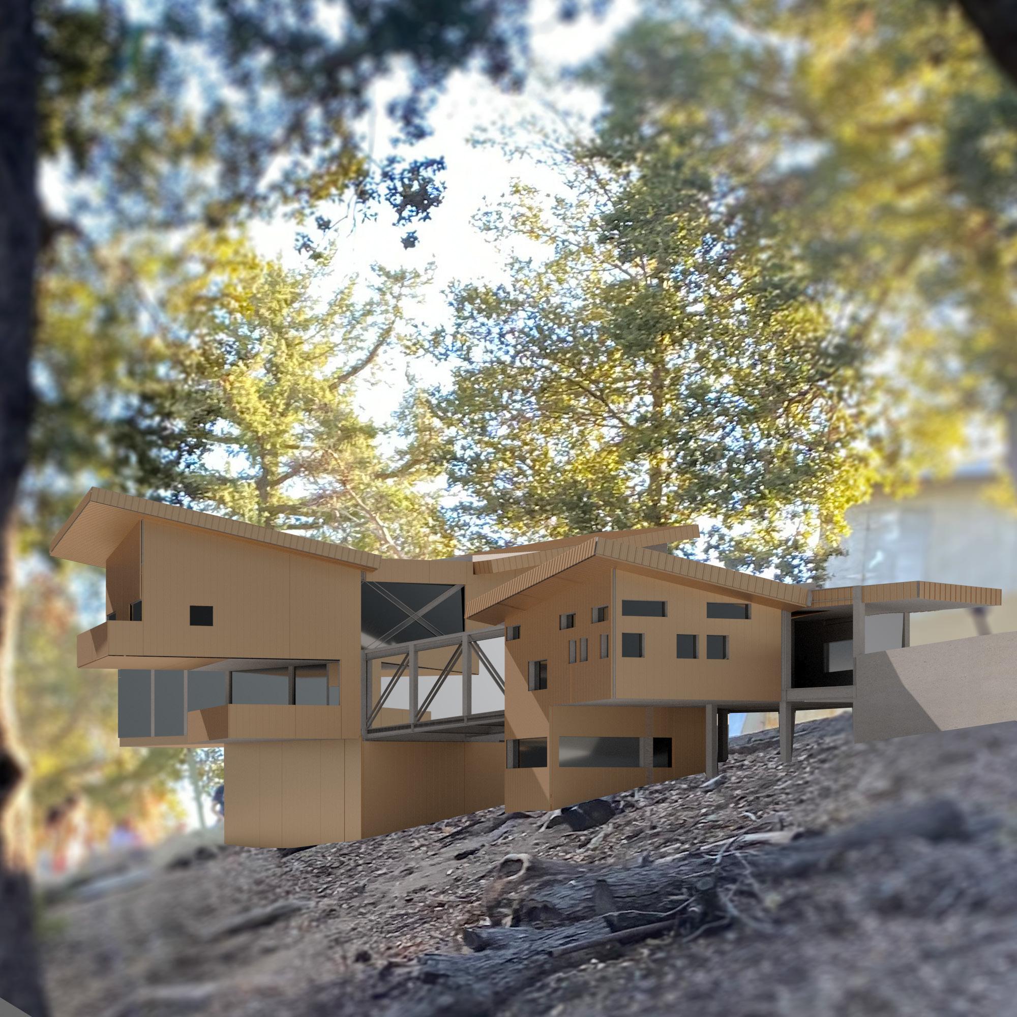
Mt. Wilson Scientist Retreat is a new facility for the researchers and for visitors. Researchers have their own living space and their research office and lab while the visitors are able to visit the facility and take a tour around the working areas.
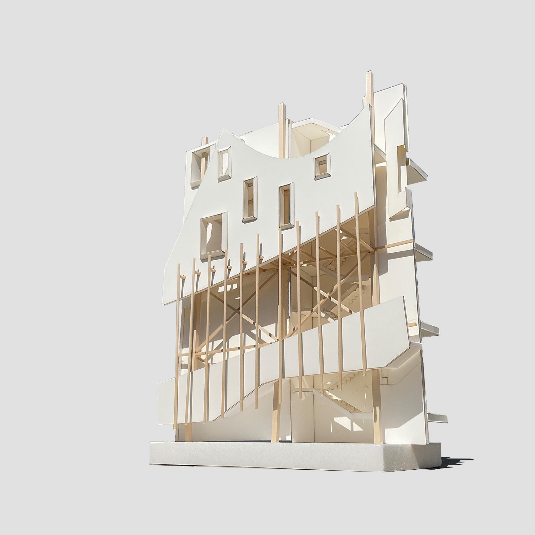
This new facility has one main feature which is the bridge that is penetrated across the entire facility. The bridge begins from the entrance of the facility and then ends at the meeting deck at the very end. This bridge is one long straight bridge that is hidden in some areas and seen in others. As both the visitors and researchers use the bridge, they can experience various spacial conditions throughout the bridge. These spacial conditions not only emphasize the difference in height but also allows the people to have a feeling of narrowness in some areas and then a feeling of wide spread in others.
Another feature of this facility is the connection between the public area and the private area. While most of these two areas are separated from each other since the private areas are spaces where researchers live, there is a certain space that these two spaces meet which allows for connections for both the researchers and the visitors. This connection is located at the bridge, close to the meeting deck. By doing this, it creates a space that breaks the barrier between the two, connecting the entire facility into one.
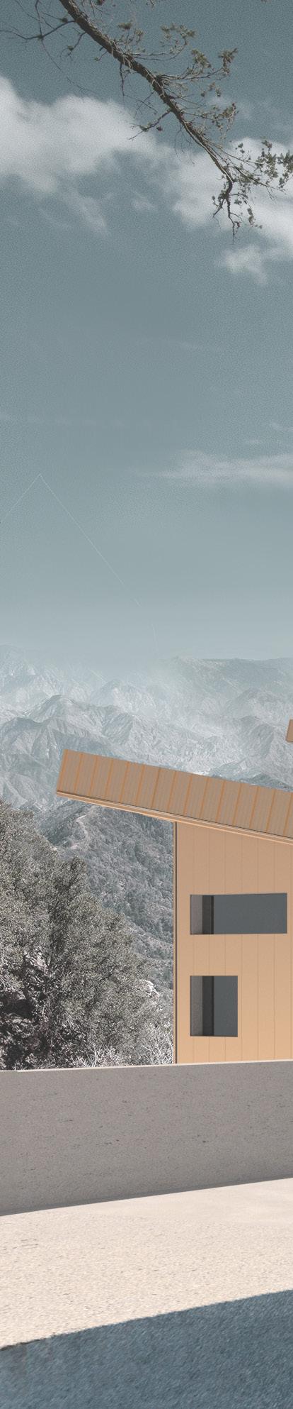
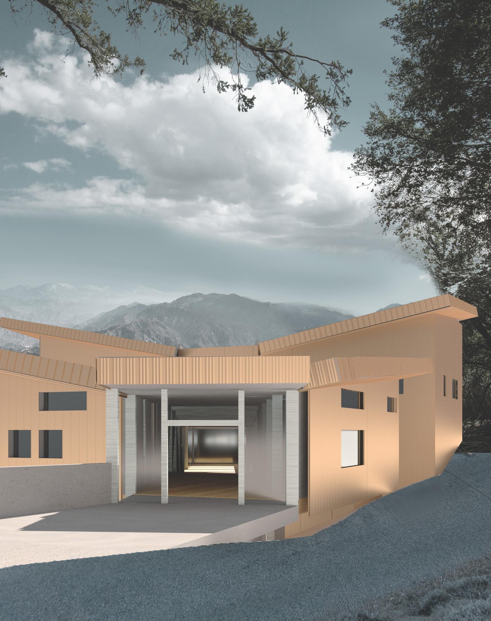
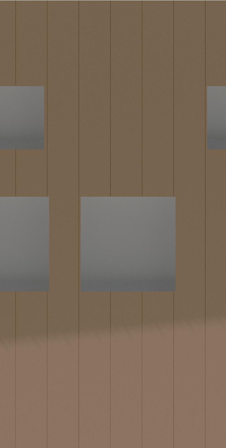
Lastly, the facility uses mostly copper material on the exterior cladding and tongue & groove wood finishes inside. With the copper finish on the outside, it blends in well with the exterior context, allowing it to blend in the summer and stand out a bit during the winter. The tongue & groove wood finish on the inside allows for a softer touch inside, being able to feel the natural element and also having an illusion of a longer space inside with all of the wall material placed in a horizontal way.
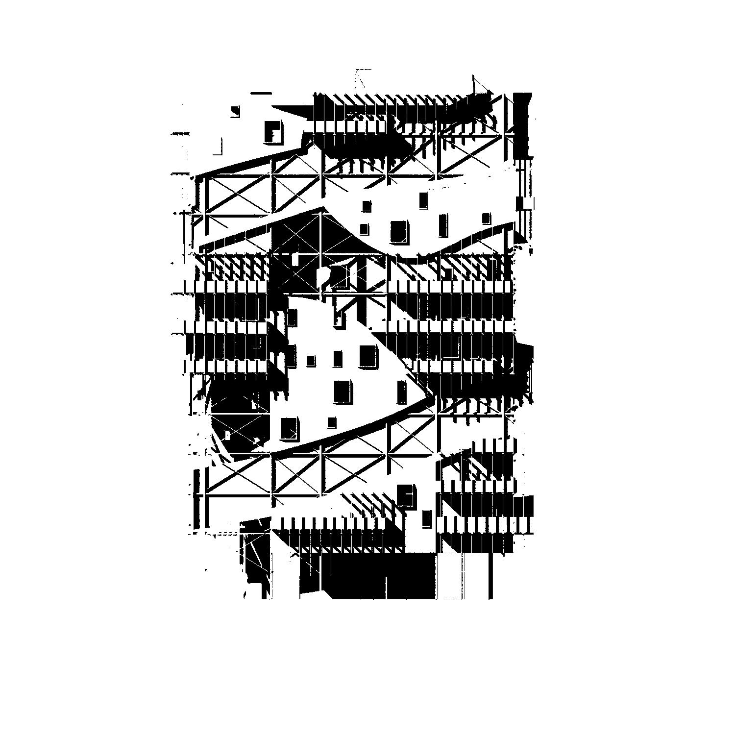
Axonometric
32 16 0 N 64 128 5 5 4 E.L. 0'-0" Shunta Abe CPP/ARC ARC3011A F2022 Site Plan Scale: 3/32” = 1’-0” DAYROOM KITCHEN STORAGE POWDER MEETING DECK (SKY) MEETING DECK (ENVIORNMENT) DECK BEDROOM BATHROOM CLOSET BEDROOM BATHROOM CLOSET SERVICE CLOSET TRASH RESEARCH OFFICE RESEARCH LAB RESTROOM PARKING Private Private Private Public Public Public Misc/Services Public Public 0' 5' 40' 10' 20' Elevation Program Diagram
EX04: Scientist Retreat CPP/ARC ARC3011A F2022 Program Diagram Site Plan
Section 4, Anton Schneider Shunta Abe
1. Lobby 2. Research Lab 3. Research Office 4. ADA Restroom 5. Meeting Deck 6. Dayroom 7. Kitchen 8. Storage 9. Powder Room 10. Parking 5. Meeting Deck 6. Dayroom 7. Kitchen 10. Parking 11. Bedroom 12. Closet 13. Bathroom
S1
E
1.
Research
Meeting Deck 6. Dayroom 7. Kitchen 10. Parking 11. Bedroom 12. Closet 13. Bathroom 33'-0" 3'-6" 18'-0" 9'-0" 9'-0" 8'-0" 11'-0" 11'-0" 32'-0" 17'-6" 39'-6" 15'-0" 8'-6" 13'-3" 32'-0"
22'-6" 17'-0"
20'-0" 6'-0" 19'-0" 16'-0" 16'-0" 15'-0" 12'-0" 12'-0" 18'-0" 9'-0" 9'-0" 8'-0" 32'-0" 32'-10" 8'-6" 12'-0" 12'-0" Ground Floor Plan Scale: 1/8” = 1’-0” Second Floor Plan Scale: 1/8” = 1’-0” Section 4, Anton Schneider Shunta Abe EX04: Scientist Retreat CPP/ARC ARC3011A F2022 Slope 2 1/2:12 Slope 2 1/2:12 E F S2 S1 5' A C B 1 5673 ft 5671 ft 5669 ft 5667 ft 2 3 E.L. + 7'-0" 0' 7 S1 S2 7 E.L. 0'-0" E.L. 3'-0" 5 5665 ft 5661 ft 10' DN 20' UP E.L. 3'-0" 9 E.L. 3'-0" 5663 ft 40' DN G H N 5677 ft D E F E.L. 0'-0" N 40' 20' 10' D A B C 4 5 3 2 1 6 5675 ft E.L. - 3'-0" 13 1 2 3 E.L. - 12'-0" 5 7 8 5 10 11 E.L. 15'-6" E.L. 16'-6" 12 12 11 5' 0' 13 4 DN 6 5 E.L. + 7'-0" E.L. 0'-0" H 10 6 4 1. Lobby 2. Research Lab 3. Research Office 4. ADA Restroom 5. Meeting Deck 6. Dayroom 7. Kitchen 8. Storage 9. Powder Room 10. Parking 5. Meeting Deck 6. Dayroom 7. Kitchen 10. Parking 11. Bedroom 12. Closet 13. Bathroom 33'-0" 3'-6" 18'-0" 9'-0" 9'-0" 8'-0" 11'-0" 11'-0" 32'-0" 17'-6" 39'-6" 15'-0" 8'-6" 13'-3" 32'-0"
22'-6" 17'-0"
20'-0" 6'-0" 19'-0" 16'-0"
15'-0" 12'-0" 12'-0" 18'-0" 9'-0" 9'-0" 8'-0" 32'-0" 32'-10" 8'-6" 12'-0" 12'-0" Slope 2 1/2:12 Slope 2 1/2:12 E F S2 S1 5' A C B 1 5673 ft 5671 ft 5669 ft 5667 ft 2 3 E.L. + 7'-0" 0' 7 S1 S2 7 E.L. 0'-0" E.L. 3'-0" 5 5665 ft 5661 ft 10' DN 20' UP E.L. 3'-0" 9 E.L.
5663 ft 40' DN G H N 5677 ft D E F E.L.
N 40' 20' 10' D A B C 4 5 3 2 1 6 5675 ft E.L.
13 1 2 3 E.L. - 12'-0" 5 7 8 5 10 11 E.L.
E.L.
12 12 11 5' 0' 13 4 DN
5 E.L.
E.L.
H 10 6 4 1. Lobby 2. Research Lab 3. Research Office 4. ADA Restroom Meeting Deck 6. Dayroom 7. Kitchen 8. Storage 9. Powder Room 10. Parking 5. Meeting Deck 6. Dayroom 7. Kitchen 10. Parking 11. Bedroom 12. Closet 13. Bathroom 33'-0" 3'-6" 18'-0" 9'-0" 9'-0" 8'-0" 11'-0" 11'-0" 32'-0" 17'-6" 39'-6" 15'-0" 8'-6" 13'-3" 32'-0" 16'-0" 22'-6" 17'-0" 16'-0" 20'-0" 6'-0" 19'-0" 16'-0" 16'-0" 15'-0" 12'-0" 12'-0" 18'-0" 9'-0" 9'-0" 8'-0" 32'-0" 32'-10" 8'-6" 12'-0" 12'-0" Ground Floor Plan Scale: 1/8” = 1’-0” Second Floor Plan Scale: 1/8” = 1’-0” Section
Anton Schneider
Scientist
CPP/ARC
Second Floor Plan Ground Floor Plan
Slope 2 1/2:12 Slope 2 1/2:12 E F S2 S1 5' A C B 1 5673 ft 5671 ft 5669 ft 5667 ft 2 3 E.L. + 7'-0" 0' 7 S1 S2 7 E.L. 0'-0" E.L. 3'-0" 5 5665 ft 5661 ft 10' DN 20' UP E.L. 3'-0" 9 E.L. 3'-0" 5663 ft 40' DN G H N 5677 ft D E F E.L. 0'-0" N 40' 20' 10' D A B C 4 5 3 2 1 6 5675 ft E.L. - 3'-0" 13 1 2 3 E.L. - 12'-0" 5 7 8 5 10 11 E.L. 15'-6" E.L. 16'-6" 12 12 11 5' 0' 13 4 DN 6 5 E.L. + 7'-0" E.L. 0'-0" H 10 6 4
33'-0" 3'-6" 18'-0" 9'-0" 9'-0" 8'-0" 11'-0" 11'-0" 32'-0" 17'-6" 39'-6" 15'-0" 8'-6" 13'-3" 32'-0" 16'-0" 22'-6" 17'-0" 16'-0" 20'-0" 6'-0" 19'-0" 16'-0" 16'-0" 15'-0" 12'-0" 12'-0" 18'-0" 9'-0" 9'-0" 8'-0" 32'-0" 32'-10" 8'-6" 12'-0" 12'-0" Slope 2 1/2:12 Slope 2 1/2:12 E F S2
5' A C B 1 5673 ft 5671 ft 5669 ft 5667 ft 2 3 E.L. + 7'-0" 0' 7 S1 S2 7 E.L. 0'-0" E.L. 3'-0" 5 5665 ft 5661 ft 10' DN 20' UP E.L. 3'-0" 9 E.L. 3'-0" 5663 ft 40' DN G H N 5677 ft D
F E.L. 0'-0" N 40' 20' 10' D A B C 4 5 3 2 1 6 5675 ft E.L. - 3'-0" 13 1 2 3 E.L. - 12'-0" 5 7 8 5 10 11 E.L. 15'-6" E.L. 16'-6" 12 12 11 5' 0' 13 4 DN 6 5 E.L. + 7'-0" E.L. 0'-0" H 10 6 4
Lobby 2.
Lab 3. Research Office 4. ADA Restroom 5. Meeting Deck 6. Dayroom 7. Kitchen 8. Storage 9. Powder Room 10. Parking 5.
16'-0"
16'-0"
16'-0"
16'-0"
16'-0"
3'-0"
0'-0"
- 3'-0"
15'-6"
16'-6"
6
+ 7'-0"
0'-0"
4,
Shunta Abe EX04:
Retreat
ARC3011A F2022
7
Section S1 Scale: 1/8” = 1’-0”
S2
1/8”
7
EX04: Scientist Retreat CPP/ARC ARC3011A F2022
5 D E F G = 1’-0”
3
2 3 1 E.L. + 9'-0"
4 5 6 E.L. 19'-0"
2 14 Section
3
4 5 6 E.L. 19'-0"
5 15
E.L. 19'-0"
A B E.L.
E.L. + 12'-6" E.L. + 12'-6"
E.L. 0'-0" ASL 5673 ft
5 15
E.L. 0'-0" ASL 5673 ft
E.L. 0'-0" ASL 5673 ft E.L. 0'-0" ASL 5673 ft
E.L. + 9'-0" E.L. - 3'-0"
E.L. + 12'-6" E.L. + 12'-6"
3'-0"
E.L. 19'-0"
E.L. + 9'-0" E.L. - 3'-0"
A B
E.L. 3'-0" C Scale:
Section S1 Scale: 1/8” = 1’-0”
Section 4, Anton Schneider Shunta Abe
EX04: Scientist Retreat CPP/ARC ARC3011A F2022 2 3 1 E.L. + 9'-0"
C 5 D E F G 2 14 Section S2 Scale: 1/8” = 1’-0”
Section 4, Anton Schneider Shunta Abe
Section S2
Section S1
Elevation (East)
DAYROOM KITCHEN STORAGE POWDER MEETING DECK (SKY) MEETING DECK (ENVIORNMENT) DECK BEDROOM BATHROOM CLOSET BEDROOM BATHROOM CLOSET SERVICE CLOSET TRASH RESEARCH OFFICE RESEARCH LAB RESTROOM PARKING Private Private Private Public Public Public Misc/Services Public Public 0' 5' 40' 10' 20' Elevation Program Diagram Section 4, Anton Schneider Shunta Abe EX04: Scientist Retreat CPP/ARC ARC3011A F2022
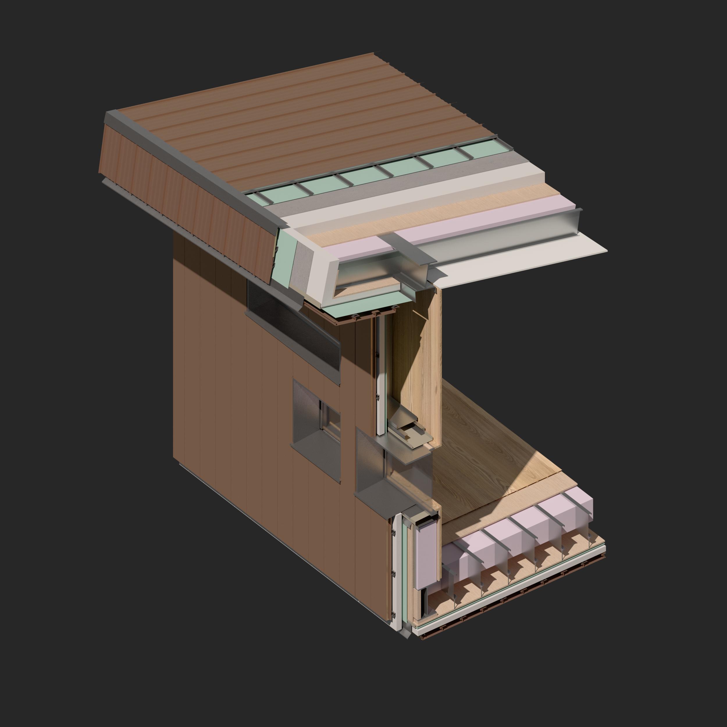
F.A. - 01 Exterior Interior Exterior Interior Nail Metal Panel (Flushed) Flashing Weather Barrier Flashing Tape Water Proofing W14x Beam Plywood Sheathing Furring Strip Corner Flashing Standing Seam Cement Board Rigid Insulation Lightgauge Joist Metal Sill Plate Metal Panel (Flushed) Flashing Tape Weather Barrier Furring Strip Nail Rigid Insulation Plywood Sheathing D - 1 D - 2 W14x Beam D - 2 R.A. - 01 Plywood Sheathing Rigid Insulation Water Proofing Cement Board Furring Strip Metal Standing Seam Batt Insulation Gypsum Wall Board Nail R.A. - 01 W.A. - 01 Nail Tongue & Groove Plywood Sheathing Batt Insulation Lightgauge Stud Plywood Sheathing Weather Barrier Rigid Insulation Furring Strip Metal Panel (Flushed) Interior Nail Furring Strip Metal Panel (Flushed) Rigid Insulation Weather Barrier Plywood Sheathing Suspension Cable Lightgauge Joist Batt Insulation W18x Beam Plywood Sheathing Tongue & Groove Finished Floor Exterior Detail Section Section 4, Anton Schneider Shunta Abe F.A. - 01 Exterior Nail Metal Panel (Flushed) Flashing Weather Barrier Flashing Tape Water Proofing W14x Beam Plywood Sheathing Furring Strip Corner Flashing Standing Seam Cement Board Rigid Insulation Backer Rod and Caulking Mullion Finished Wood Cap Shim Pan Flashing Flexible Flashing Plywood Sheathing Track Boxed Track D - 1 D - 2 W.A. - 01 Tongue & Groove Nail Tongue & Groove Plywood Sheathing Batt Insulation Lightgauge Stud Plywood Sheathing Weather Barrier Rigid Insulation Furring Strip Metal Panel (Flushed) Nail Furring Strip Metal Panel (Flushed) Rigid Insulation Weather Barrier Plywood Sheathing Suspension Cable Lightgauge Joist Batt Insulation W18x Beam Plywood Sheathing F.A. - 01 Exterior Nail Metal Panel (Flushed) Flashing Weather Barrier Flashing Tape Water Proofing W14x Beam Plywood Sheathing Furring Strip Corner Flashing Standing Seam Cement Board Rigid Insulation Backer Rod and Caulking Mullion Finished Wood Cap Shim Pan Flashing Flexible Flashing Plywood Sheathing Track Boxed Track D - 1 D - 2 W.A. - 01 Tongue & Groove Nail Tongue & Groove Plywood Sheathing Batt Insulation Lightgauge Stud Plywood Sheathing Weather Barrier Rigid Insulation Furring Strip Metal Panel (Flushed) Nail Furring Strip Metal Panel (Flushed) Rigid Insulation Weather Barrier Plywood Sheathing Suspension Cable Lightgauge Joist Batt Insulation W18x Beam Plywood Sheathing F.A. - 01 Exterior Interior Exterior Interior Nail Metal Panel (Flushed) Flashing Weather Barrier Flashing Tape Water Proofing W14x Beam Plywood Sheathing Furring Strip Corner Flashing Standing Seam Cement Board Rigid Insulation Backer Rod and Caulking Mullion Finished Wood Cap Shim Pan Flashing Flexible Flashing Plywood Sheathing Lightgauge Joist Track Boxed Track Metal Sill Plate Metal Panel (Flushed) Flashing Tape Weather Barrier Furring Strip Nail Rigid Insulation Plywood Sheathing D - 1 D - 2 W14x Beam W.A. - 01 D - 2 D - 1 F.A. - 01 R.A. - 01 Plywood Sheathing Rigid Insulation Water Proofing Cement Board Furring Strip Metal Standing Seam Batt Insulation Gypsum Wall Board Nail R.A. - 01 W.A. - 01 Tongue & Groove Nail Tongue & Groove Plywood Sheathing Batt Insulation Lightgauge Stud Plywood Sheathing Weather Barrier Rigid Insulation Furring Strip Metal Panel (Flushed) Interior Nail Furring Strip Metal Panel (Flushed) Rigid Insulation Weather Barrier Plywood Sheathing Suspension Cable Lightgauge Joist Batt Insulation W18x Beam Plywood Sheathing Tongue & Groove Finished Floor Exterior Wall Section R.A. - 01 W.A. - 01 F.A. - 01 D - 01 D - 02
Waterproof Membrane
Plywood Sheathing Rigid Insulation Cement Board
Lightgauge Steel Joist Batt Insulation
Suspension Cable
Finished Gypsum Wall Board
Furring Strip
Corner Flashing Waterproof Membrane Cement Board Flashing Flashing Tape Weather Barrier
Corten Steel Standing Seam
Track Box Track Flexable Flashing Double Pane Glass Sill Plate Mullion Pan Flashing Flexible Flashing Flashing Weather Barrier Flashing W18 Beam W14 Beam Axonometric Chunk
Lightgauge Steel Batt Insulation Plywood Sheathing Plywood Sheathing Tongue & Groove Finished Floor
Truss Span: 38' Depth by RoT: 38'/5 = 7.6'
Beam Span: 16' Depth by RoT: 16'/15 = 12.8"
Joist Span: 18' Depth by RoT: 18'/20 = 10.8"
Girder Span: 12' Depth by RoT: 12'/10 = 14.4"
Beam Span: 16' Depth by RoT: 16'/15 = 12.8"
Truss Span: 38' Depth by RoT: 38'/5 = 7.6'
Joist Span: 18' Depth by RoT: 18'/20 = 10.8"
Girder Span: 12' Depth by RoT: 12'/10 = 14.4"
Structure Diagram
4,
EX04: Scientist Retreat CPP/ARC ARC3011A F2022
Section
Anton Schneider Shunta Abe
Exterior Render
THIRD YEAR FALL 2022
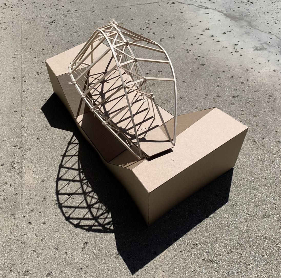
This new bridge is aimed for creating a viewing deck that people are able to look down at and also have elements that are both unique and blend in well in the forested condition around. This suspended bridge has wires that go down to the flooring which supports the load that is applied at both the viewing deck and the main circulation.
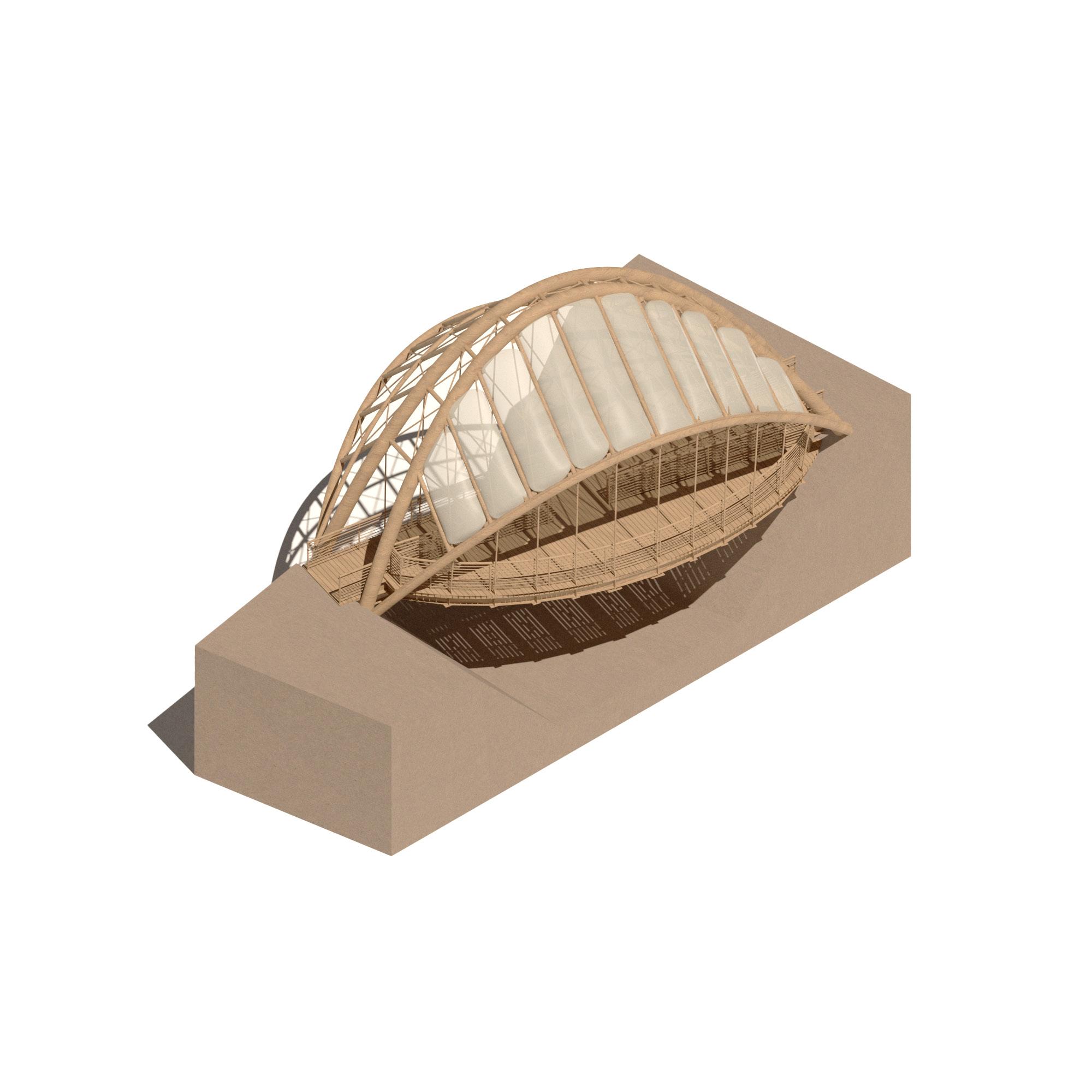
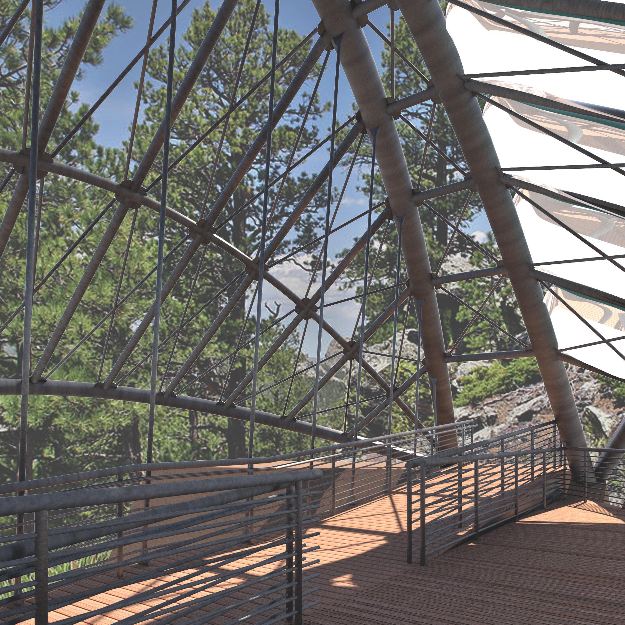
One main feature of this bridge is the asymmetrical portion. The bridge contains a viewing deck on only one side of the bridge, causing more load on that one side. To counteract the forces, the wings that extend from the main arc are adjusted so that it will balance out with the load applied at the viewing deck. The wings are extended farther on the side with no viewing deck than the other. This not only counteracts the forces but the extended wings also makes the people look down below the bridge because of the long structural wing. However, if people do want to see farther out, they can also do this as well because the wing that is extended longer does not have a roof material compared to the viewing deck.
Lastly, even though this bridge is created mostly from metal to support the load, it still blends in well with the environment around it being brushed and having a darker color to the material itself. The roof is polycarbonate, allowing light to enter but at the same time blocking any water feature from above.
Axonometric 02
BRIDGE PROJECT IN FORESTED MOUNTAIN
A B
6
5'-6 1 2 " 24'-5" 6'-5 1 2 " 1'-0" 6'-9 1 4
4
24'-5 1 4 "
6'-0"
R2 A
Bottom Landing (E.L. 0’-0”)
Intermediate Landing (E.L. 2’-0”)
B 1
5 Ground Floor Plan
2
3
1 1 2
Top Landing (E.L. 4’-0”) R1
Path of Water Gutter Underground Drainage Platform Circulation
Circulation Diagram Roof Drainage Diagram
6'-0" Elevation
1'-0" 6'-9 1 4 " 2
A
0 1 2 4 8’
10'-3 1 4 "
3'-6" Bottom Landing (E.L. 0’-0”)
1 1 2 " 5'-11" 1
3'-0 3 4 " 1'-0" 24'-5 " 6'-5 1 2 24'-5" 3'-6" Top Landing (E.L. 4’-0”) Intermediate Landing (E.L. 2’-0”) Bottom Landing (E.L. 0’-0”) R1 R2 E.L. 0’ - 0”
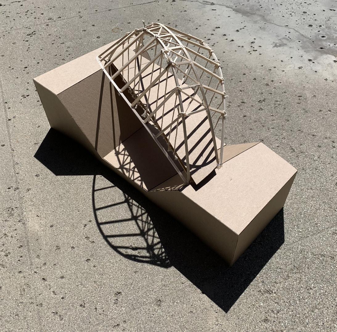
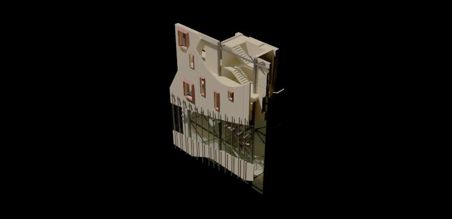
Model Photo
Axonometric
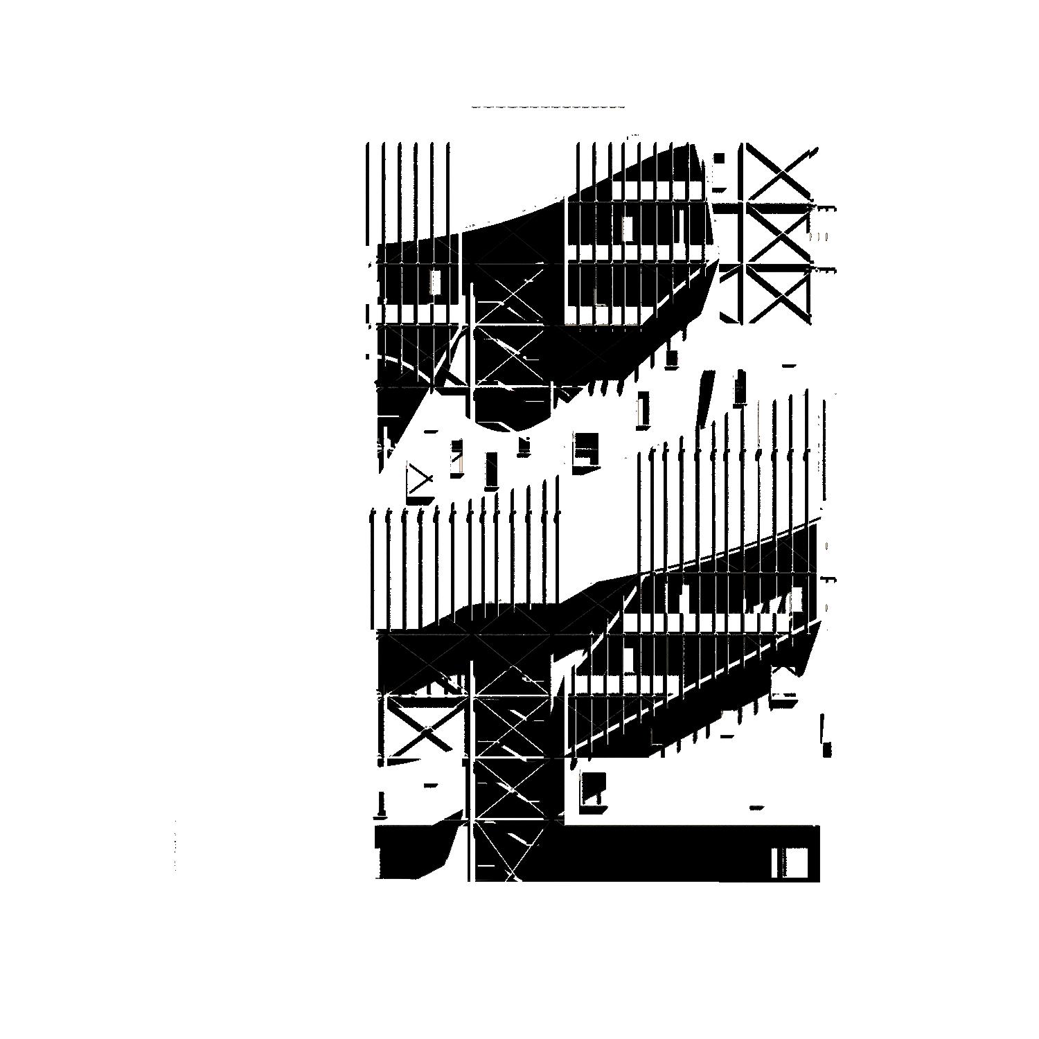
Long Section
03 School of Architecture
Cal Poly Pomona, Pomona
SECOND YEAR SPRING 2022
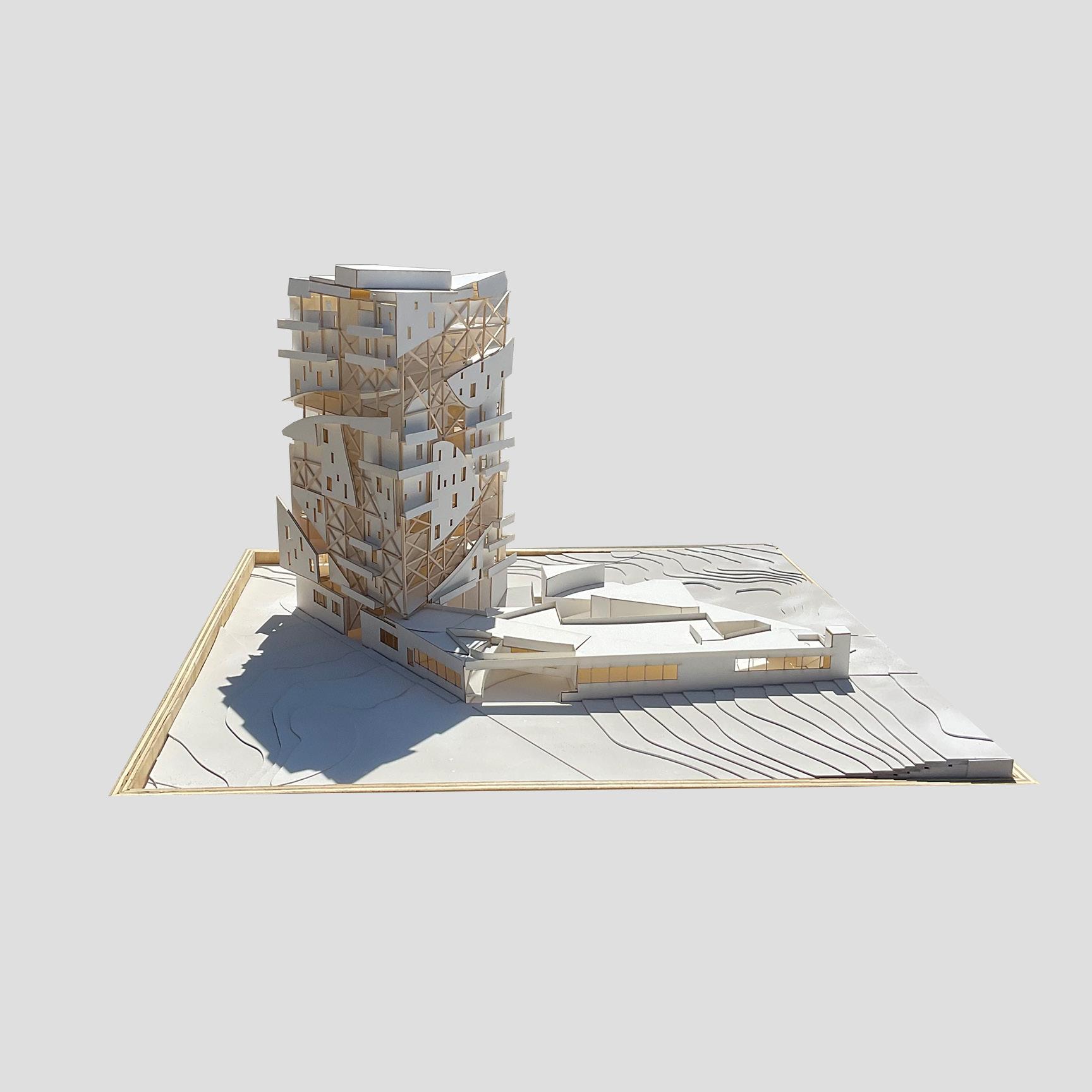
The new School of Architecture building is a building that not only represents the architecture students but the entire campus. This new tower and the new plinth, connects to the surrounding while having its own unique elements. The tower and the plinth have a couple of concepts that have made the basis of this project.
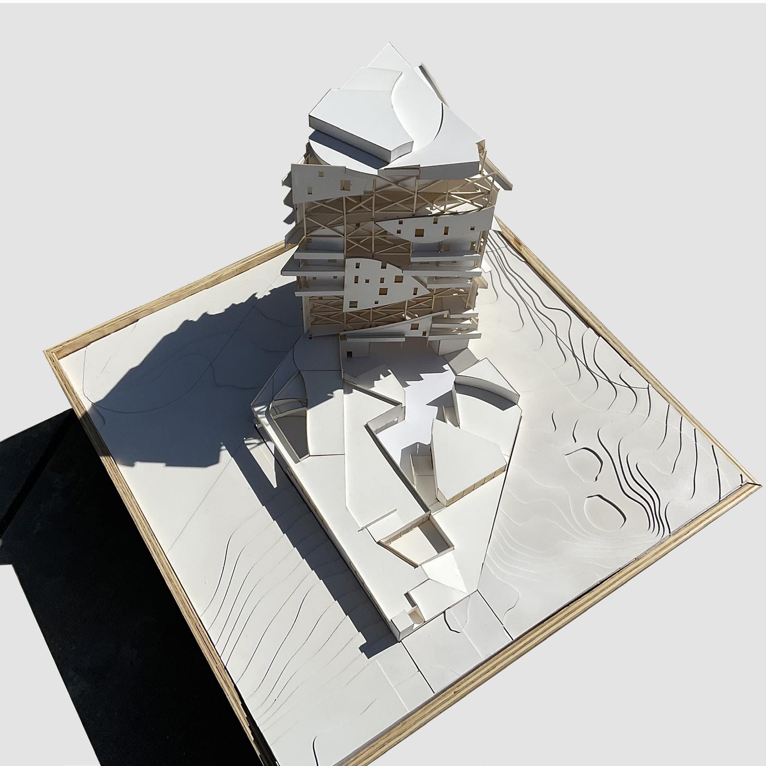
The first concept is the materiality of the tower. The tower consists of 3 different materials (glass, concrete, and metal) which creates a unique facade. The glass and concrete are used for exterior skin of the building and the metal is used for structural materials. The second concept is the circulation that wraps around the building. This circulation path starts from the second level to the roof level, connecting each floor. There are also pathways on the plinth roof that lead to this main circulation. The third concept is the use of extrusions. Each level has different types of extrusions made from the facade which creates an unique interior space for each floor. The plinth also contains this element, having many extrusions for each program. Lastly, the plinth has a concept to block the east side of the building and allow full access through the northwest side where the Japanese garden is. This deliberate connection with the garden and the building creates the connection between the site and the plinth.
With these different concepts, the tower and plinth aims to show the idea of how architecture is always moving forward but at the same time, looking back in time. The different types of materiality, the exposure of the structures, the extrusions, and circulations makes the building very iconic and at the same time, makes the plinth a connected, relaxing space.
Axonometric
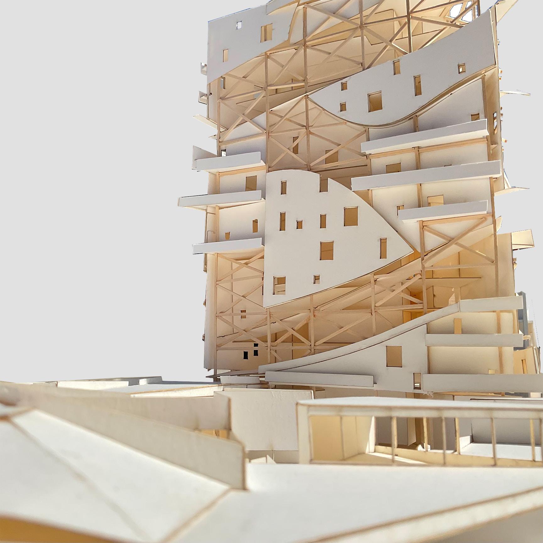 Model Close-Up VIew
Summer Sun Path Winter Sun Path Wind Pedistrian Vehicle Site
Plan Model Top View
6 3 2 5 5 4 1 5 UP UP UP UP UP UP 7 UP 7 A B 1 2 3 1 Gallery 2 Fabrication Lab 3 Model Shop 4 Lecture 5 Seminar 6 Reception 7 Storage 0 5 15 35 (ft) Hardscape Softscape Ground Floor Plan 1/16” = 1’ - 0” Ground Floor Plinth Plan
1 1 2 3 DN 1
2
2 2 DN DN UP UP UP
0
Studio Desks
Breakout Rooms
Second Floor Plan 1/16” = 1’ - 0”
5 15 35 (ft) Second Floor Plan
Ground Floor Floor 1.5 (Entrance only to Seminar) Floor 2 Floor 3 Floor 4 Floor 5 Floor 6 Floor 7 Floor 8 Floor 9 Floor 10 Floor 11 Floor 12 Roof Floor 0 5 15 35 (ft) 1 Gallery 7 Storage 1 7 Section A
Elevation 3 (North)
Elevation 2 (SouthWest)
1/16” = 1’ - 0”
Elevation 2 (SouthWest)
35 (ft)
0 5 15
Painted Contrete Facade Exterior Egress Stairs Main Circulation Glass Enclosure Steel Bars Steel Structure Columns
Facade
Detail
Model Detail Facade
04 Museum of Japanese Contemporary Art
Little Tokyo, Los Angeles
SECOND YEAR FALL 2021
This project “The Japanese Museum of Contemporary Arts” is located at Little Tokyo, Los Angeles and is about 20,000 square feet big. The new museum has several different concepts that dictate this museum including the connection of the museum to its surroundings, the different lighting effects and its special circulation.
To connect the museum to the site location, an extended plaza was created to connect the flow of the people. This allows the people to go through the museum without actually entering it and gives the people a glance of what they might see in the museum.

Throughout the museum there are several openings on the top of the museum, allowing light to pass through the different rooms. There is a very thin bay on the roof with one of them being louvers to allow light into the museum. The atrium is another source that allows lighting to enter the plaza region below
Lastly, this project has a dedicated circulation bay at the far end of the building. This circulation is not only created for simple movement but is created as another quality of the building. The circulation leads to a dramatic ending where the two different types of gallery on the top floor.
Axonometric
0 5 10 20 40 (ft)
SERVICE
STREET Site Plan
+16'-0"
ALLEY 0'-0" EAST 1st
GALLERY LOBBY SCULPTURE GARDEN CAFE AUDITORIUM BOOKSTORE CLASSROOM OFFICE BACKROOM CIRCULATION EGRESS STAIR STAFF CIRCULATION MAIN CIRCULATION Program Diagram
Circulation Diagram
A A B C B A A B C B 0 5 10 20 (ft) 1 2 3 4 5 6 DN DN DN UP DN UP UP DN DN 7 8 9 10 11 DN UP UP DN UP B C B A A A A B C B UP DN UP DN DN UP 0 5 10 20 (ft) Third Floor Plan 8 BOOKSTORE 9 PREPERATION ROOM 10 MECHANICAL 11 STORAGE Second (Plaza) Floor Plan 2 GALLERY 3 SCULPTURE GARDEN
Section B
Section C
Section A
2 3 4 0 5 10 20 (ft) 5 6 8 9 7 1 2 2 0 5 10 20 (ft) 1 2 2 6 9 3 2 4 7 8 5 0 5 10 20 (ft)
1
2
3
4
5 CLASSROOM 6
7 CAFE 8 BOOKSTORE 9 BACKROOM
LOBBY
GALLERY
SCULPTURE GARDEN
OFFICE
AUDITORIUM
2 GALLERY 3 SCULPTURE
4 OFFICE 5 CLASSROOM 7 CAFE 8 BOOKSTORE 1
2
6
9
GARDEN
LOBBY
GALLERY
AUDITORIUM
BACKROOM
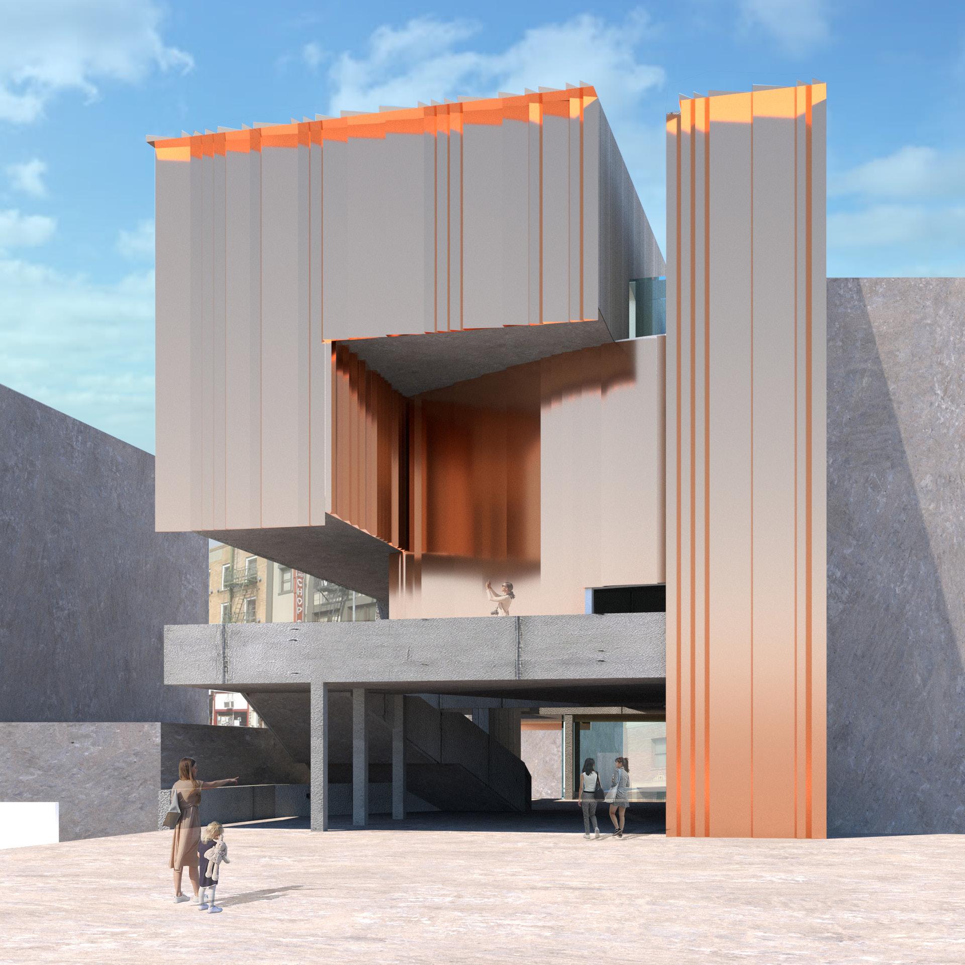
Exterior Facade
Elevation A Elevation B
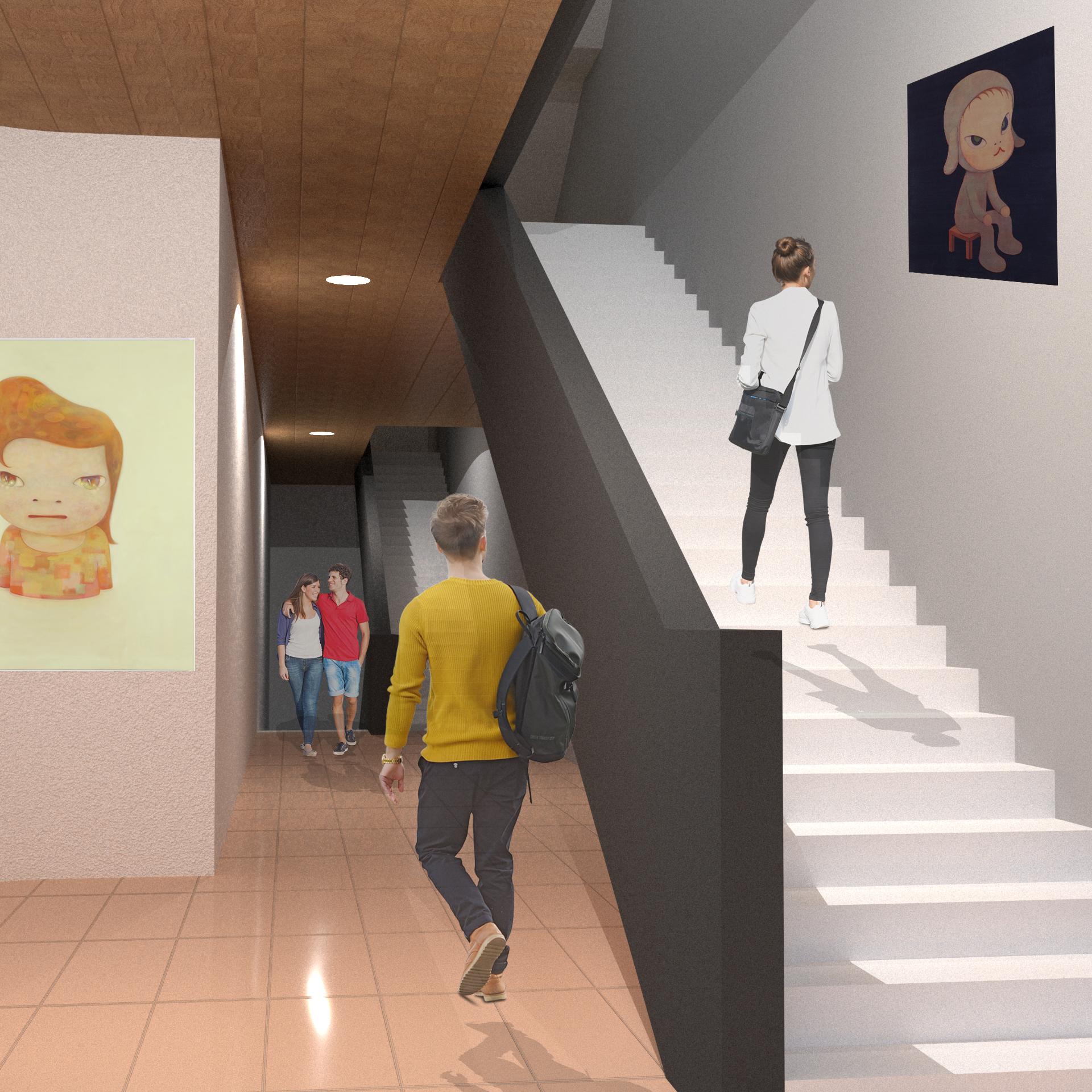 Interior CIrculation
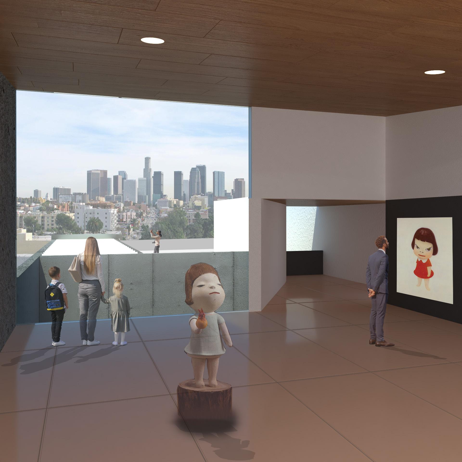
Top Gallery View
Thank You