Product: BACKHOE LOADER
Model: 432F BACKHOE LOADER PXR Configuration: 432F Backhoe Loader Side Shift PXR00001-UP (MACHINE) POWERED BY C4.4 Engine
416F, 420F, 422F, 428F, 430F, 432F, 434F and 444F Backhoe Loaders Power Train Media Number -UENR2303-02 Publication Date -01/04/2013 Date Updated -15/04/2013
Axle
SMCS - 3256-016; 3258-016; 3260-016; 4251-016
S/N - FBN1-UP
S/N - FLY1-UP
S/N - LBH1-UP
S/N - LDH1-UP
S/N - LJJ1-UP
S/N - LNR1-UP
S/N - LRH1-UP
S/N - PXR1-UP
S/N - RAK1-UP
S/N - SEJ1-UP
S/N - SJW1-UP
C 235-2784
Adjusting Tool Gp 1
E 1P-0520 Driver Gp 1
F 235-2790 False Pinion 1
G 235-2792 False Differential 1
H 6V-2012 Depth Micrometer 1
J 154-9731 Thread Lock Compound -
K 069-4707 Sealant 1 L
8T-5096 Dial Indicator Gp 1 207-0478 Socket Assembly 1 207-0485 Adjustment Tool 1 207-0481 Adjustment Tool 1
M 129-1938 Grease Cartridge -
NOTICE
Keep all parts clean from contaminants.
Contaminants may cause rapid wear and shortened component life.
Note: Cleanliness is an important factor. Before assembly, thoroughly clean all parts in cleaning fluid. Allow the parts to air dry. Do not use wiping cloths or rags to dry parts. Lint may be deposited on the parts which may cause trouble. Inspect all parts. If any parts are worn or damaged, use new parts for replacement. Dirt and other contaminants can damage the precision component. Perform assembly procedures on a clean work surface. Keep components covered and protected at all times.
Note: Check the O-ring seals and the seals for wear or for damage. Replace the components, if necessary.
Illustration 1 g01641381
1. Lower the temperature of bearing cups (67). Use Tooling (E) to install bearing cups (67) into the center housing.
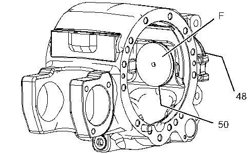
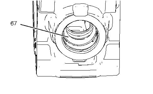
Illustration 2 g01649194
2. Install bearing cones (50) and (48). Install Tooling (F).
Illustration 3 g01649293
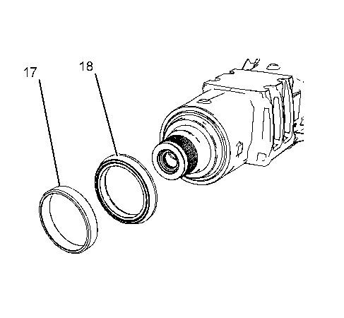
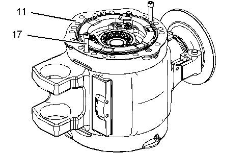
3. Align the location marks that were made during the removal procedure. Position brake cylinder assembly (11) and temporarily install bolts (17). Repeat for the opposite side.
Illustration 4 g01649294
4. Install Tooling (G) into the center housing. Make sure that Tooling (G) is inserted into both brake cylinders.


Illustration 5 g01649295
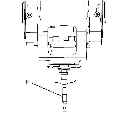
Illustration 6 g01555354
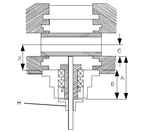
5. Use Tooling (H) to measure Distance (A). Distance (B) equals 145 mm (5.709 inch). Distance (C) equals 50 mm (1.968 inch). Use the following formula to calculate Measurement (X): A mm + C mm - B mm = X mm. Record Measurement (X). Illustration 7 g01649313
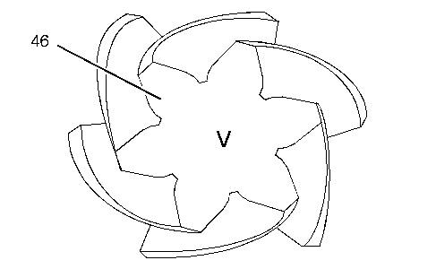
6. Measurement (V) is stamped on the head of pinion shaft (46). Use the following formula to calculate Measurement (S): X mm - V mm = S mm.
7. Among the available shims, choose the shim with the thickness of Measurement (S). The shim will be installed in Step 9.
Illustration 8 g01649314
8. Remove Tooling (G). Remove brake cylinder assemblies (11). Remove the nut and the washer from Tooling (F) and remove Tooling (F). Remove bearing cones (48) and (50).
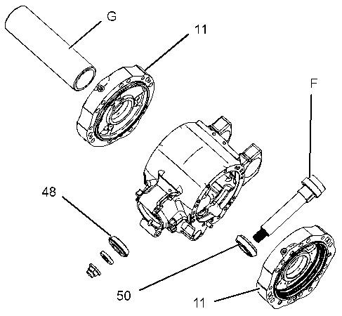
Illustration 9 g01649474
9. Install the shim from Step 7 onto pinion shaft (46). Install the shim with the chamfer against the gear. Raise the temperature of bearing cone (50) and install bearing cone (50) onto pinion shaft (46).
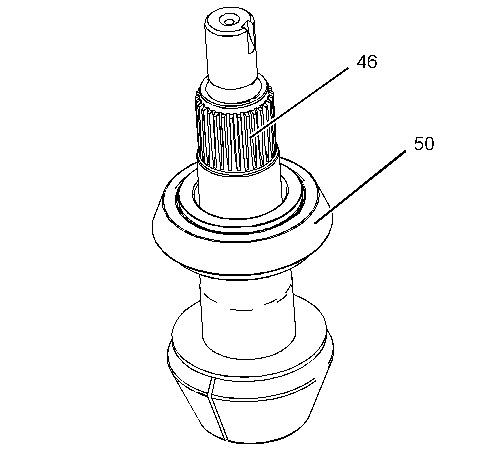
Illustration 10 g01649476
10. Install washers (49) and a new collapsible spacer (47) onto pinion shaft (46).
Illustration 11 g01649479
11. Install pinion shaft (46) into the center housing. Raise the temperature of bearing cone (48) and install bearing cone (48) onto pinion shaft (46).
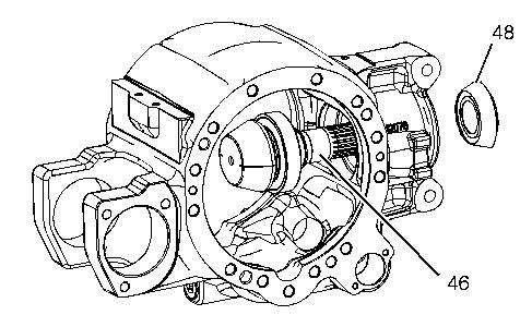
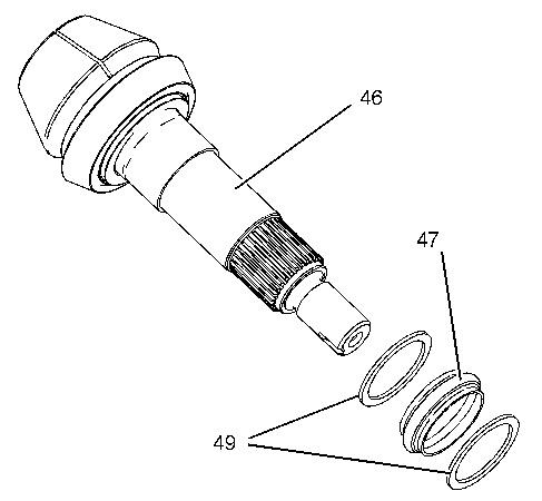
Illustration 12 g01638835
12. Install lip seal (45) into the center housing.
Illustration 13 g01641791 13. Install brake disc (42), O-ring seal (43), washer (44), and nut (41).
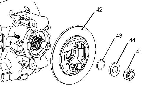

Illustration 14 g01649481
14. Use Tooling (C) to hold brake disc (42). Tighten nut (41). Continue to tighten nut (41) to achieve a rotating torque of 4.126 to 4.460 N·m (36.518 to 39.474 lb in). Illustration 15 g01638818


15. Install thrust washer (37) and side gear (38). Install spider (36), gears (35), and thrust washers (34).

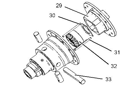
Illustration 16 g01637983
16. Install planetary shafts (33). Install locking pins (31). Install side gear (32) and thrust washer (30). Install cover (29).
Illustration 17 g01637981
17. Install pins (27), the seals, and collar (28).
Illustration 18 g01637979
18. Install bevel gear (25) onto the differential. Apply Tooling (J) to the threads of bolts (24). Install bolts (24) and tighten bolts (24) to a torque of 180 N·m (133 lb ft).

Illustration 19 g01641544
19. Raise the temperature of bearing cones (23) and (26). Install bearing cones (23) and (26).
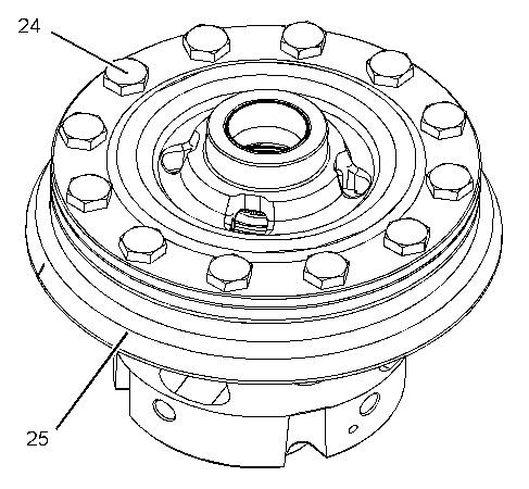
Illustration 20 g01639081
Improper assembly of parts that are spring loaded can cause bodily injury.
To prevent possible injury, follow the established assembly procedure and wear protective equipment.
20. Install fork (58) into the center housing. Install retaining ring (57) onto rod (55). Install rod (55) into fork (58).
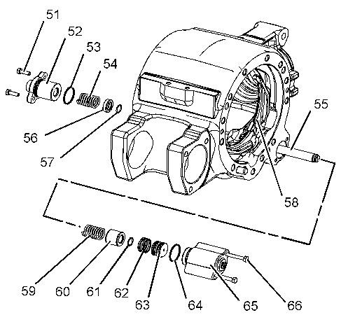
21. Install washer (56) and spring (54) onto rod (55).
22. Install O-ring seal (53) onto cover (52). Install cover (52) and bolts (51). Tighten bolts (51) to a torque of 20 to 24 N·m (15 to 18 lb ft).
23. Install spring (59), bushing (60), and retaining ring (61) onto rod (55).
24. Install O-ring seals (62) onto piston (63). Install piston (63) into cover (65).
25. Install O-ring seal (64) onto cover (65). Install cover (65) and bolts (66). Tighten bolts (66) to a torque of 20 to 24 N·m (15 to 18 lb ft).
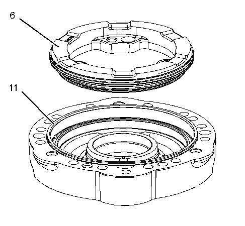
Illustration 21 g01641550
26. Apply a thin coat of Tooling (M) onto O-ring seals (5). Install O-ring seals (5) onto brake piston (6). Repeat this step for the opposite side.
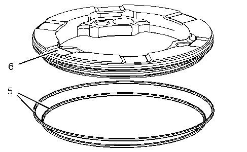
Illustration 22 g01641551
27. Install brake piston (6) into brake cylinder assembly (11). Make sure that the holes on brake piston (6) align with the holes in brake cylinder assembly (11). Make sure that brake piston (7) is installed all the way to the bottom of brake cylinder assembly (11). If necessary, tap brake piston (6) with a suitable rubber mallet to install brake cylinder assembly (11) completely to the bottom. Repeat this step for the opposite side.

Illustration 23 g01641574
28. Install bolts (16), retainers (15), springs (14), springs (13), and bushings (12), as an assembly. Install bolts (10), washers (9), bushings (8), and spacers (7). Tighten bolts (10) to a torque of 10 N·m (89 lb in). Tighten the bolts for springs (16) to a torque of 10 N·m (89 lb in). Repeat this step for the opposite side.
Illustration 24 g01641778
29. Position brake cylinder assembly (11) on a flat surface. Use Tooling (E) to install bearing cup (21). Repeat this step for the opposite side.
Illustration 25 g01641782
30. Use Tooling (A) to install spanner nut (22) into brake cylinder assembly (11). Repeat this step for the opposite side.
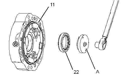
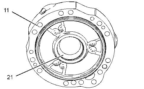
Illustration 26 g01641802
31. Apply Tooling (K) to the mating surfaces of the center housing and one brake cylinder assembly (11). Align the location marks that were made during the removal procedure. Position brake cylinder assembly (11) on the side that is opposite of the bevel gear, and onto the center housing. Install bolts (17). Tighten bolts (17) to a torque of 79 ± 4 N·m (58 ± 3 lb ft).
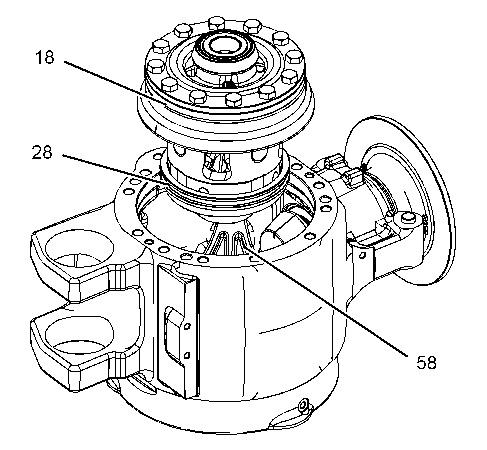
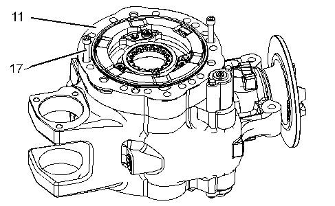
Illustration 27 g01641803
32. Install the differential and bevel gear assembly (18) into the center housing.
Note: Ensure that collar (28) engages fork (58).
Illustration 28 g01641804
33. Apply Tooling (K) to the mating surfaces of the center housing and brake cylinder assembly (11). Align the location marks that were made during the removal procedure. Position brake cylinder assembly (11) onto the center housing and install bolts (17). Tighten bolts (17) to a torque of 79 ± 4 N·m (58 ± 3 lb ft).
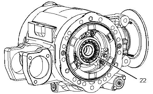
Illustration 29 g01650293
34. Oscillate the pinion shaft and use Tooling (A) to advance spanner nuts (22) until there is slight backlash with no end play.
Illustration 30 g01641805
35. Install a dial type torque wrench onto pinion shaft (46). Measure the total rotating torque. Use the following formula to calculate the total rotating torque (TRT): P equals the rotating torque that was measured in Step 14. TRT = P + 0.519 N·m (4.593 lb in) to P + 0.778 N·m (6.885 lb in)
36. If the total rotating torque (TRT) is less than the specified amount, tighten both spanner nuts equally. If the total rotating torque (TRT) is greater than the specified amount, loosen both spanner nuts equally. Be sure to always maintain slight backlash.
37. Use a suitable hammer and a punch to stake nut (32).
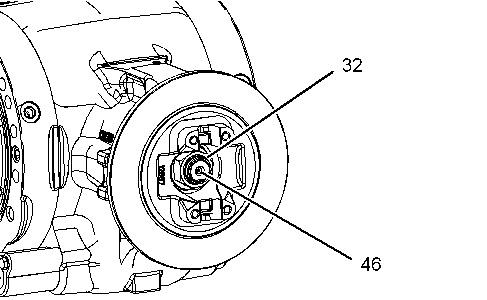
Illustration 31 g01641806
Typical example 38. Mount Tooling (L) onto the center housing. Measure the backlash between the pinion and the bevel gear. The proper backlash setting is 0.18 to 0.32 mm (0.007 to 0.013 inch).
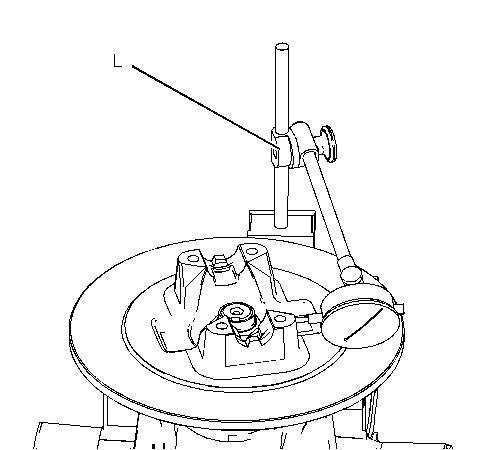
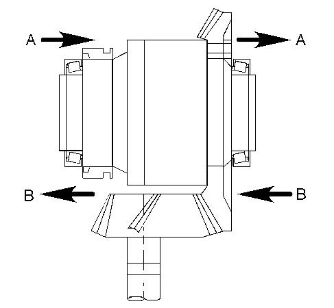
Illustration 32 g01449257
39. If the backlash is not within the specification, retract one spanner nut and advance the opposite spanner nut equally. This will maintain the bearing preload. If the backlash is less than the specified amount, move the bevel gear in Direction (A). If the backlash is greater than the specified amount, move the bevel gear in Direction (B).
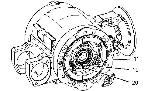
Illustration 33 g01641796
40. Install retainer (19) and bolt (20) into both brake cylinder assemblies (11). Tighten bolts (20) to a torque of 13 N·m (10 lb ft). Repeat this step for the opposite side.
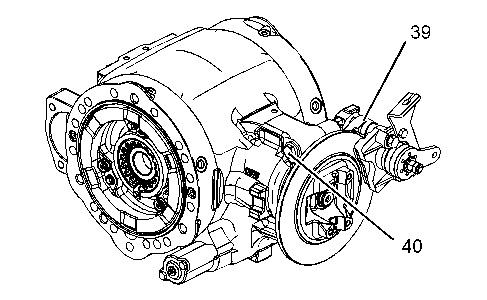
Illustration 34 g01641808
41. Apply Tooling (J) to the threads of bolts (40). Position brake assembly (39) and install bolts (40).
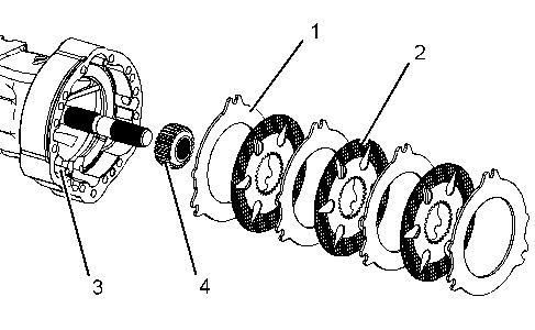
Illustration 35 g01636808
Note: Make sure that you align the tear-shaped holes in brake discs (2) to provide proper flow of oil for cooling, as shown.
42. Install dowels (3). Install brake hub (4) with brake discs (2) and plates (1) into the brake cylinder assembly.

a. Install the axle housing. Refer to Disassembly and Assembly, "Axle Housing, Axle Shaft, and Wheel Flange - Install".
Copyright 1993 - 2019 Caterpillar Inc. All Rights Reserved. Private Network For SIS Licensees.
Fri Sep 27 21:01:18 UTC+0800 2019
Previous Screen
Product: BACKHOE LOADER
Model: 432F BACKHOE LOADER PXR
Configuration: 432F Backhoe Loader Side Shift PXR00001-UP (MACHINE) POWERED BY C4.4 Engine
Disassembly and Assembly
416F, 420F, 422F, 428F, 430F, 432F, 434F and 444F Backhoe Loaders Power Train Media Number -UENR2303-02 Publication Date -01/04/2013 Date Updated -15/04/2013
Axle Housing, Axle Shaft, and Wheel Flange - Assemble
SMCS - 3260-016; 4057-016; 4234-016
S/N - FBN1-UP
S/N - FLY1-UP
S/N - JWJ1-UP
S/N - KSF1-UP
S/N - LBH1-UP
S/N - LDH1-UP
S/N - LDY1-UP
S/N - LJJ1-UP
S/N - LKH1-UP
S/N - LNH1-UP
S/N - LNR1-UP
S/N - LRH1-UP
S/N - LTG1-UP
S/N - LWT1-UP
S/N - PXR1-UP
S/N - RAK1-UP
S/N - RDF1-UP
S/N - RGS1-UP
S/N - SEJ1-UP
S/N - SJW1-UP
S/N - SKR1-UP
Assembly Procedure
Table 1
Required Tools
Tool Part Number Part Description Qty
A 230-7923 Spanner Wrench 1
B 1P-1861 Retaining Ring Pliers 1
C 1P-0520 Driver Gp 1
Note: Cleanliness is an important factor. Before assembly, thoroughly clean all parts in cleaning fluid. Allow the parts to air dry. Do not use wiping cloths or rags to dry parts. Lint may be deposited on the parts which may cause trouble. Inspect all parts. If any parts are worn or damaged, use new parts for replacement. Dirt and other contaminants can damage the precision component. Perform assembly procedures on a clean work surface. Keep components covered and protected at all times.
Illustration 1 g01546055
Illustration 2 g01546098
1. Use Tooling (C) in order to install bushing (20) and seal (19). Install bushing (20) and seal (19) to the depth of Dimension (A). Dimension (A) is measured from Surface (X) to seal (19). Dimension (A) is equal to 9.0 mm (0.35 inch).
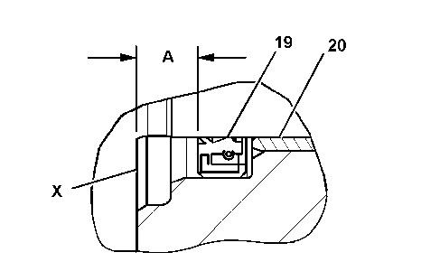
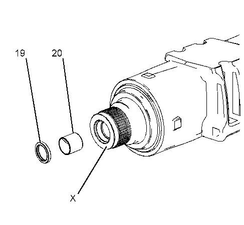
Illustration 3 g01545954
2. Raise the temperature of bearing cone (18). Install bearing cone (18). Install spacer (17).