CONTENT
ACADEMIC WORKS
01 LIVING AS YOU WANT
An attempt of Design democrization based on computation tools
02 WEAVING CLOUD
Functional Architecture Design Based On 3D Printing
03 EXTENSION OF HANDS
Robotic Arm Construction and Fabrication
04 CYBER FAIRYTALE
3D-Printing Houte Couture
Skills
Advanced Intermediate Beginner
Rhinoceros, Grasshopper, AutoCAD, Photoshop, Sketchup, InDesign, Enscapte, Microsoft Office
Python, Adobe Illustrator, Revit, Processing, Vray, Arduino, Figma
Java, C++, Unity3D, Blender
OTHER WORKS

WEAVING CLOUD
FUNCTIONAL ARCHITECTURE DESIGN BASED ON 3D PRINTING
Type: Academic Work, Collaborative Work Collabrator: Du Jian
Contribution: Concept Design, Modeling and Coding, Printing Experiment, Drawing. Instructor: Hua Hao
Date: 04/2022-06/2022
1
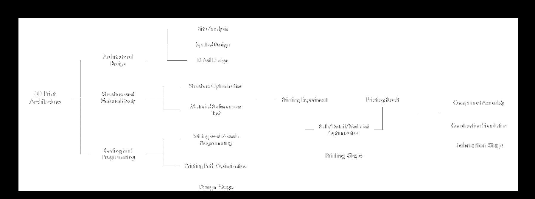
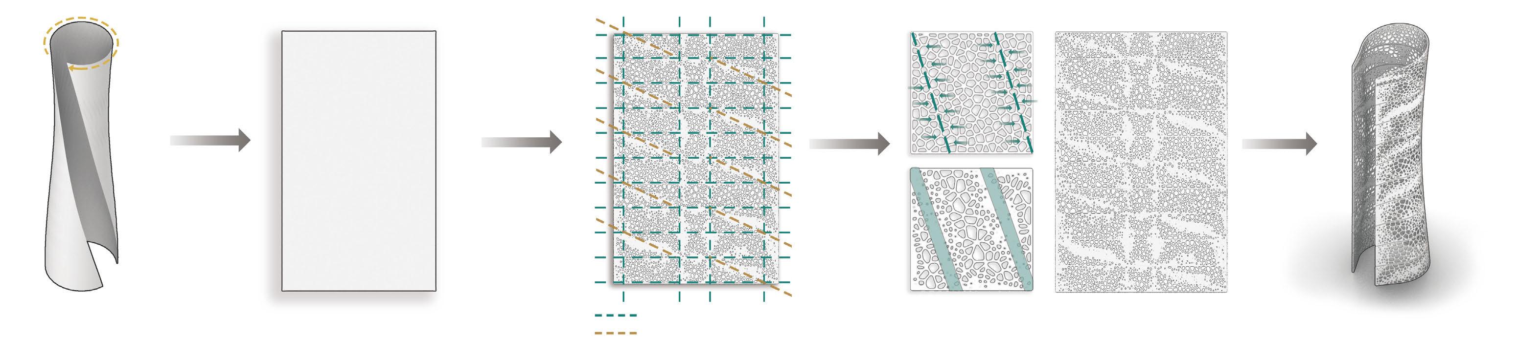
Additive manufacturing technology, also known as 3D printing technology, has great prospects in the industrial and construction fields.3D printing technology in architecture can integrate design and construction, providing a new and systematic perspective for today's architecture to study the form, material, structure and other architectural elements.
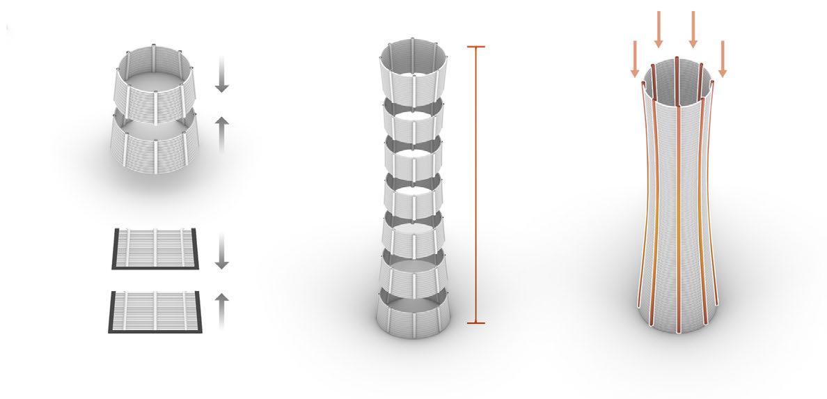
At present, conventional 3D printed architecture still have limitations due to factors such as device size, material and printing methods. In this project, we propose an 3D print method that combines multiple materials. Single-layer component sizes are controlled by slicing in layers, while using traditional architecture material for connection and reinforcement. Thus, the scale and form freedom of 3D printed buildings can be greatly improved, and the disadvantages of 3D printed materials in mechanical properties can be avoided to a certain extent.
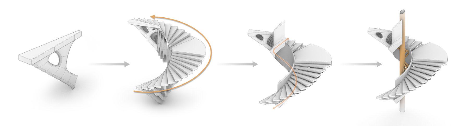
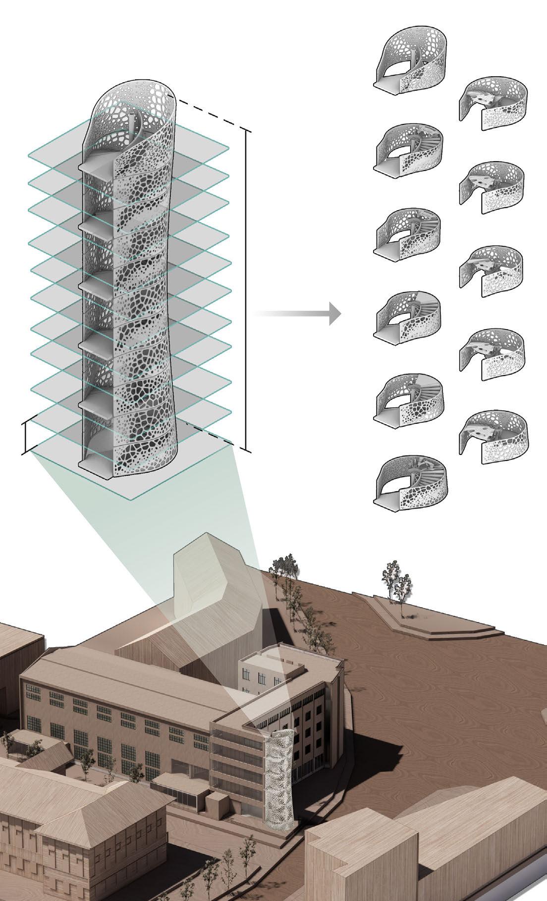
1.3 VOLUMN GENERATION
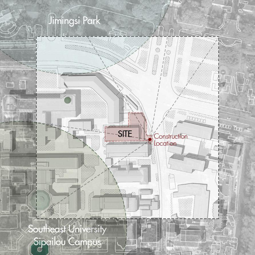
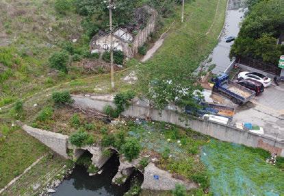
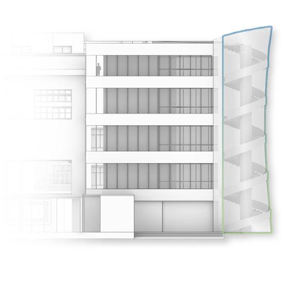
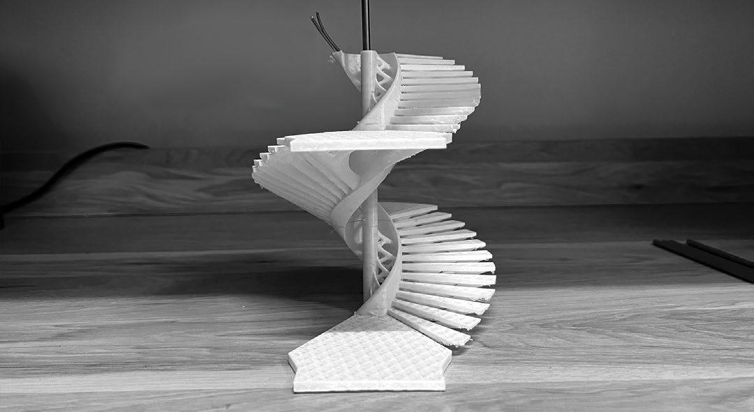
The site is located on the edge of an old building on the northeast side of the Southeast University campus, which used to be a material and structural laboratory and has been abandoned for a long time. Now the university is trying to convert the building into a new research building, and the projectl is planning to add a new stairwell as a traffic space, using 3d printing as the basic design method.
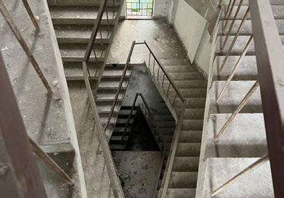
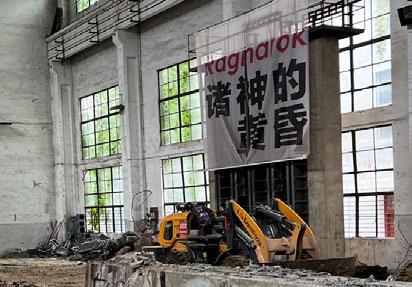
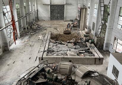
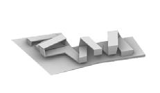
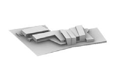
Since the stairwell to be designed was added to the side of the original building, the structure exists independently of the original building. This is reflected in the process of volume generation, where the structure and envelope of the stairwell are generated separately from the original building, and form a harmonious rhythm with the original building.
PART 2 STRUCTURE DESIGN AND FABRICATION
2.1 STEPS AND PLATFORM DESIGN
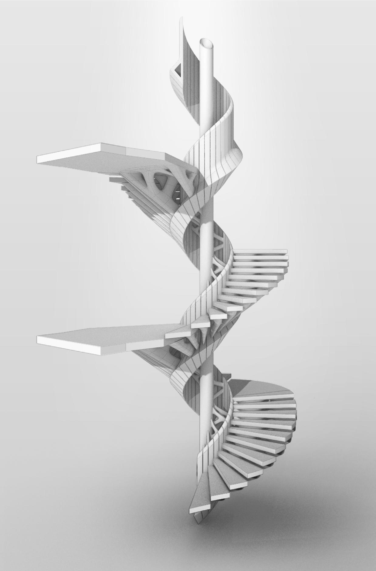
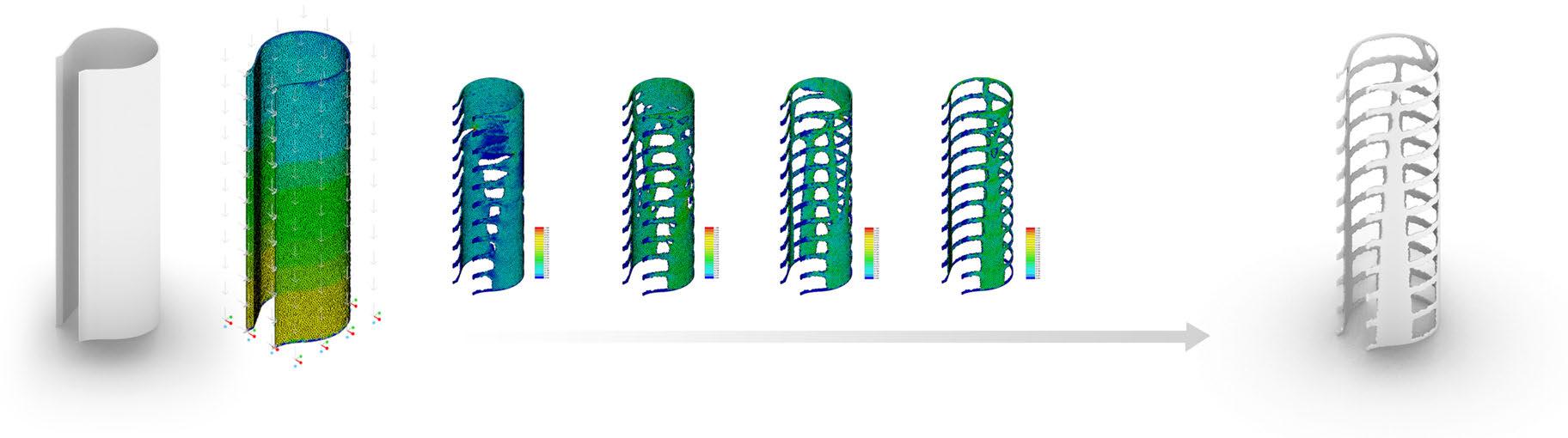
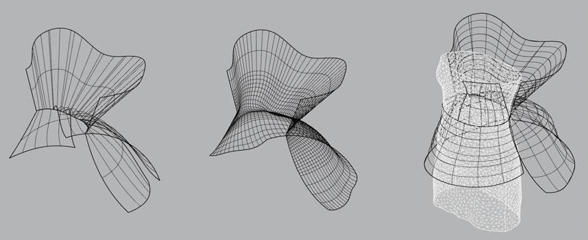
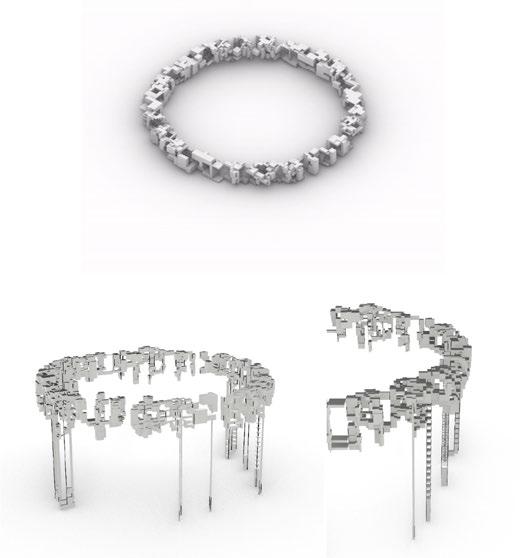
To design a staircase as a traffic space, the step is the main content of the structure design. Firstly, topology optimization and finite element analysis is used to design a step unit that meets the structural requirements and is easy to print. It then designs connections that are easy to assemble in layers and transfer loads to the core structure.
2.1.1 STEPS AND PLATFORM OPTIMIZATION
Add Steps and Platforms Reinforce and Connect to Main Structure
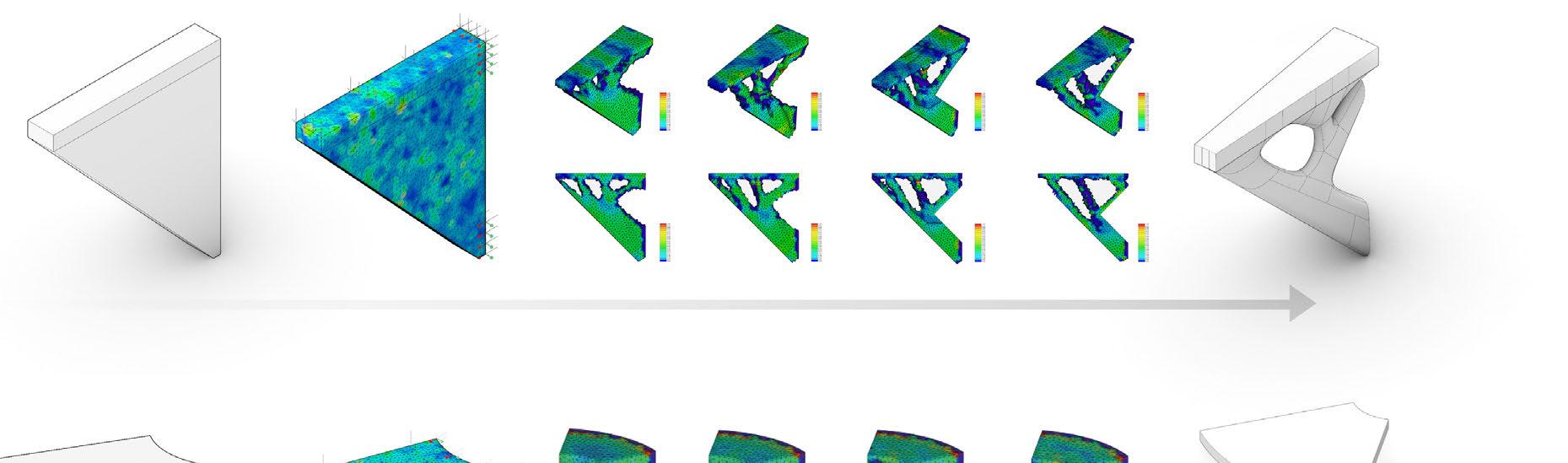
Steps & Surpport Topology Optimization Extract and Rebuild
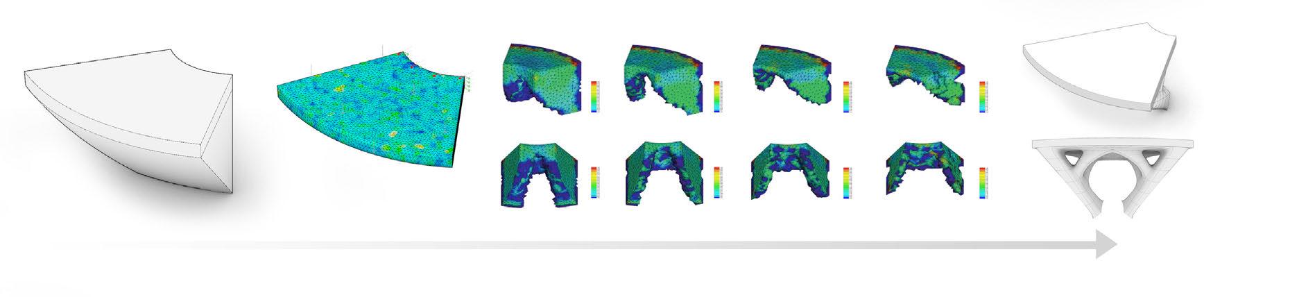
Platform Topology Optimization Extract and Rebuild
2.1.2 STRUCTURE REINFORCEMENT
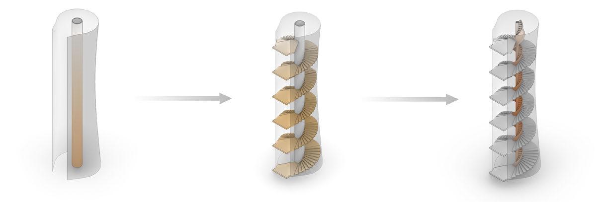
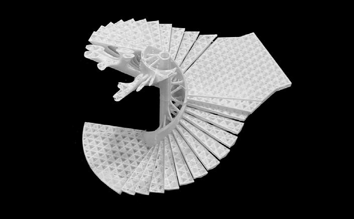
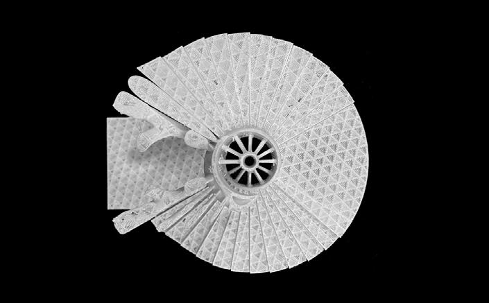
Optimized Step Unit Arrange units along the spiral upward direction
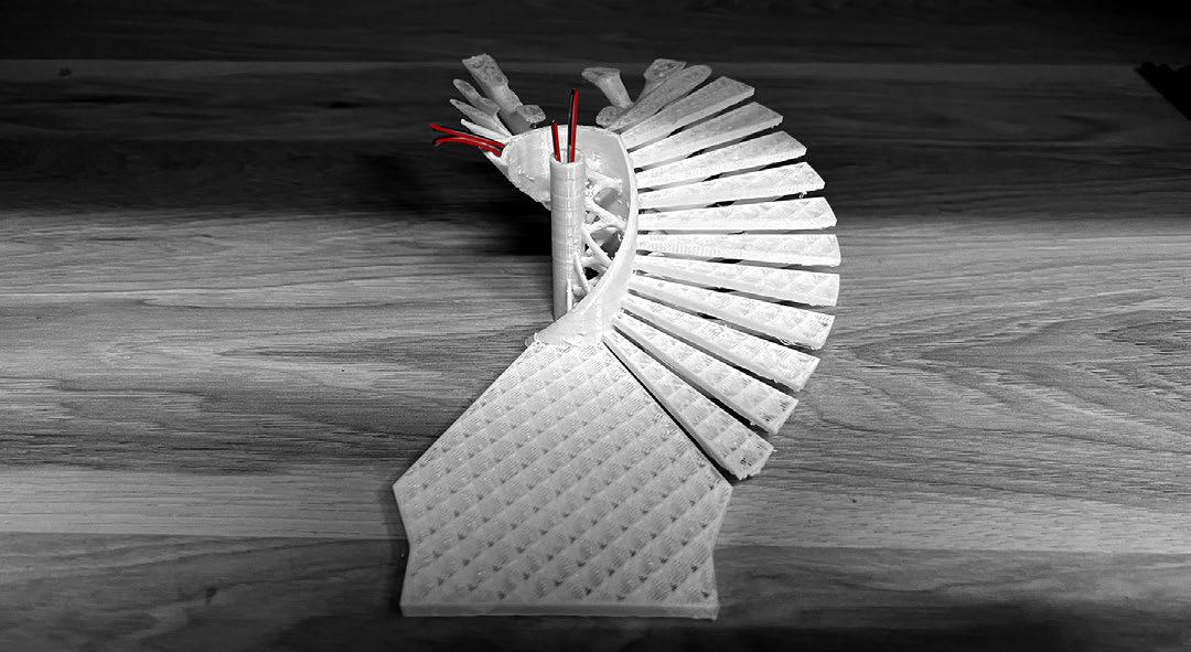
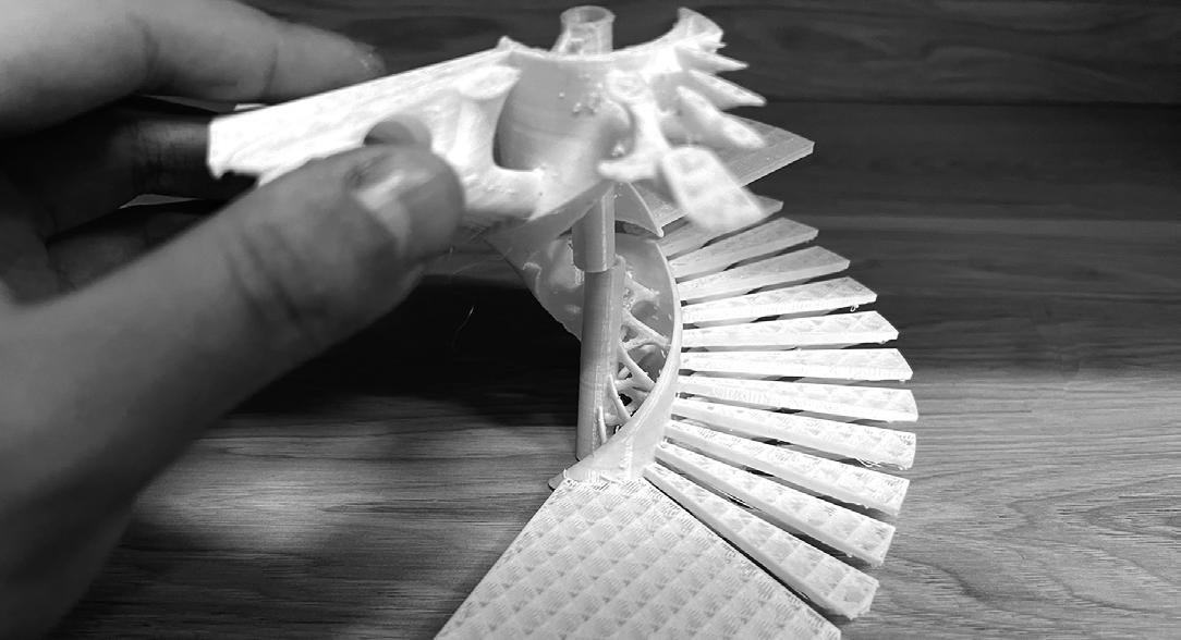
One side of the staircase is fixed and reinforced by steel cable
Connect the staircase to the main column through trusses
PART I DESIGN BACKGROUND AND CONCEPT
1.1 PROJECT BACKGROUND
1.2 SITE ANALYSIS
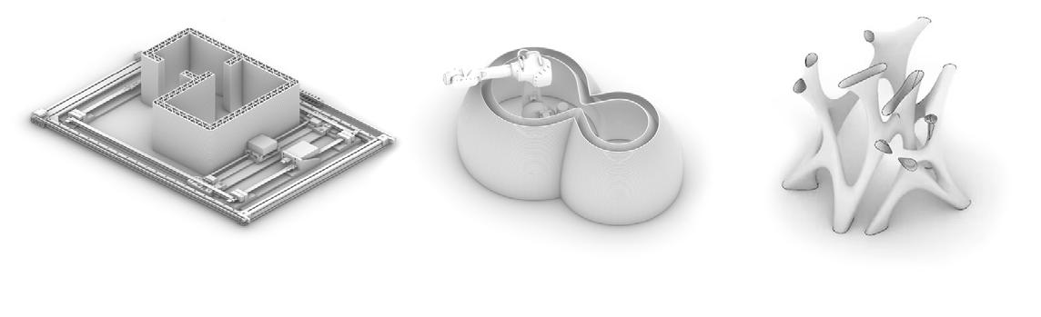
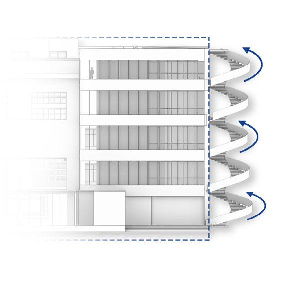
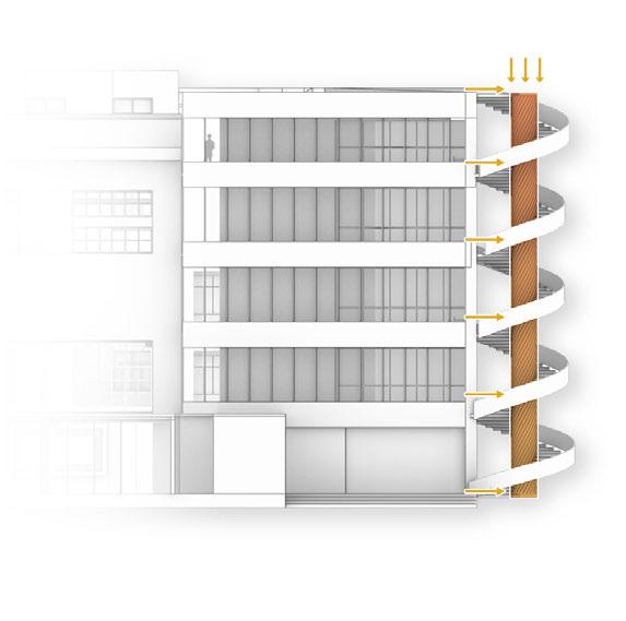
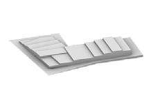
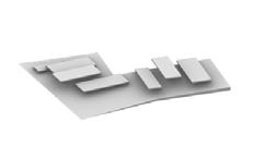
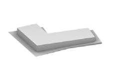
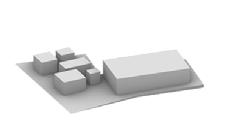
Step 1 Generating Spiral Staircases on the Side of the Existed Building. Step 2 Erecting a Pillar in the Center of the Stairs to Bear the Main Load Step 3 Erecting a Pillar in the Center of the Stairs to Bear the Main Load Concrete Formwork Print On-Site Robotic Arm Print Prefabricated Components Print 3 typical 3d printing building applications Current 3D-Print Restriction Angle restrictions prevent some parts such as floor slabs from being printed Size is Limited by printer size The material strength is limited due to the mechanical properties of the print material Assembly Layer Component Advantage
Print angles that cannot be printed in general printing methods, such as floor slabs. By stacking multiple layers, the height of the printed building can be increased By structure reinforcement, the structural performance can be improved. 2 3
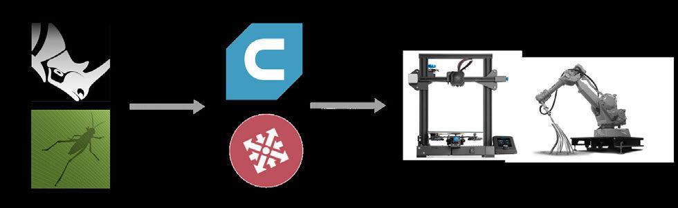
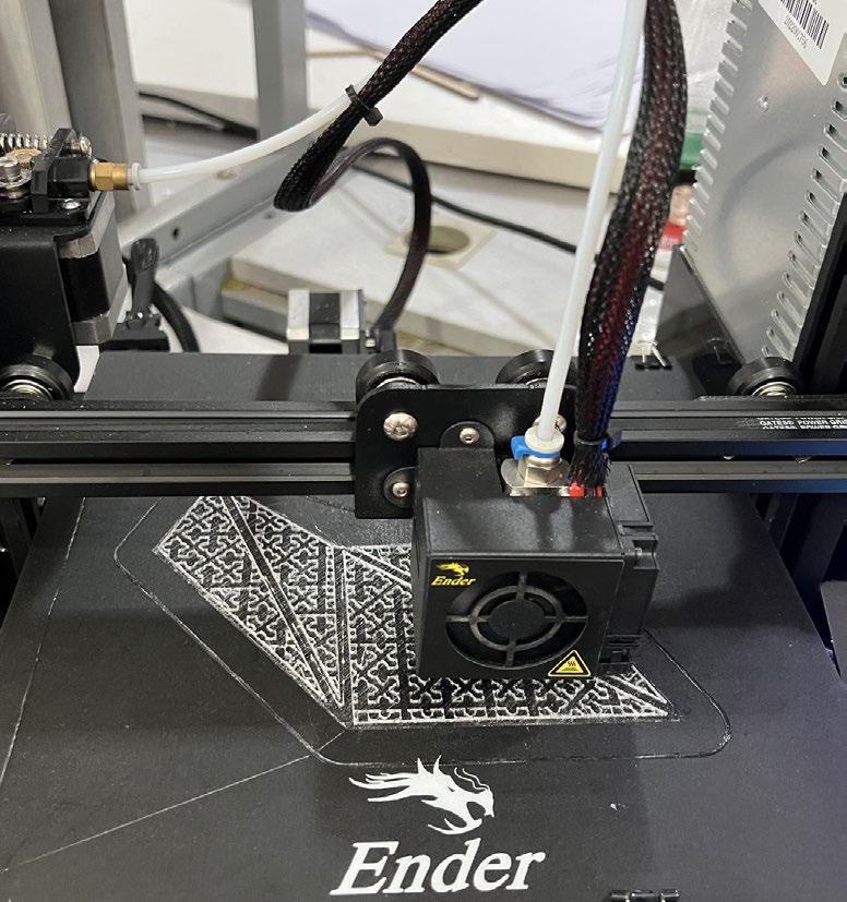
PRINTING PROCESS
Additive manufacturing technology, also known as 3D printing technology, has great prospects in the industrial and construction fields.3D printing technology in architecture can integrate design and construction, providing a new and systematic perspective for today's architecture to study the form, material, structure and other architectural elements.


ASSEMBLAGE SIMULATION
PART 3 SURFACE DETAIL DESIGN
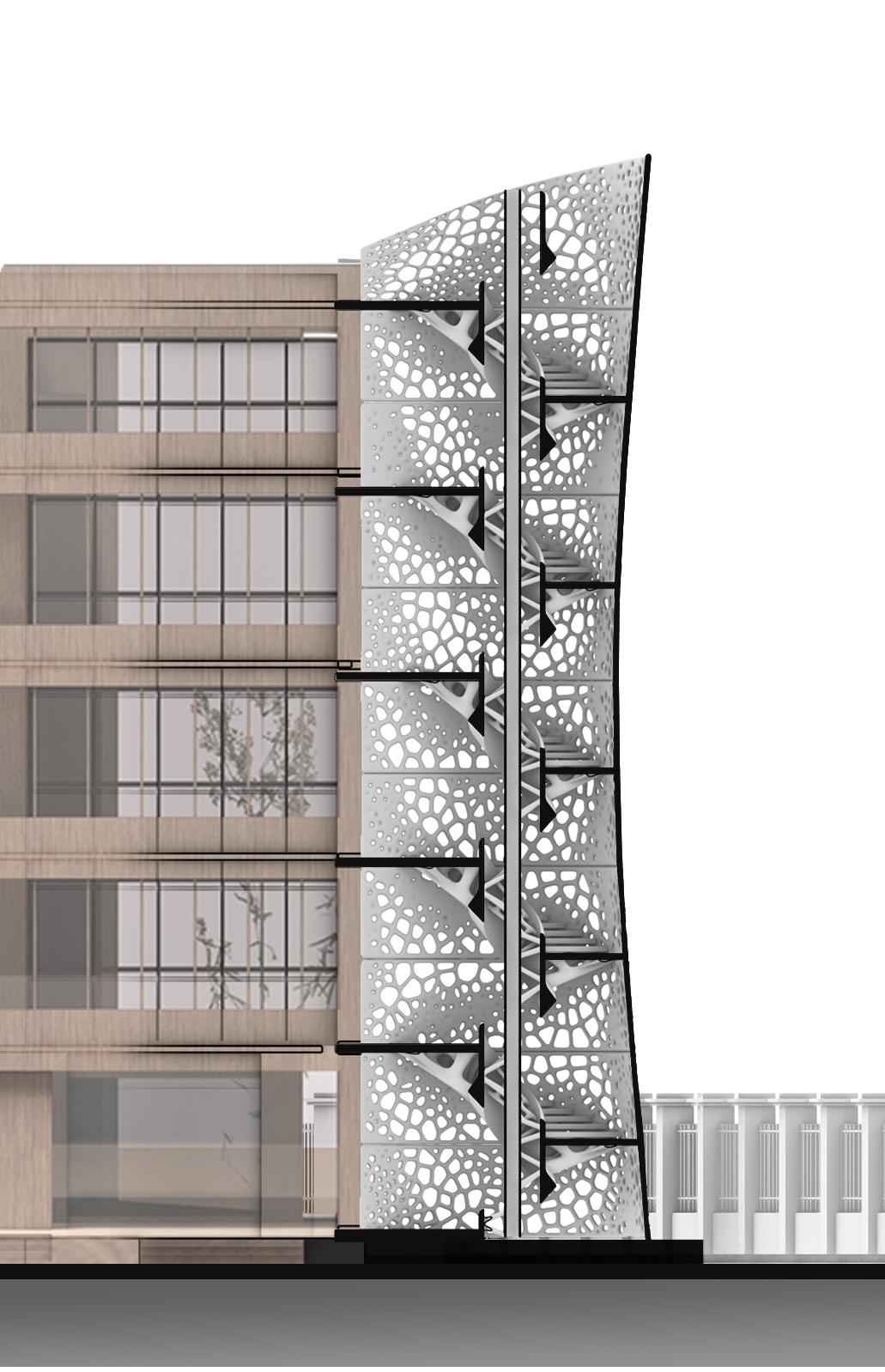
2.2 ENVELOPE DESIGN
To design a staircase as a traffic space, the step is the main content of the structure design. Firstly, topology optimization and finite element analysis is used to design a step unit that meets the structural requirements and is easy to print. It then designs connections that are easy to assemble in layers and transfer loads to the core structure.
To design a staircase as a traffic space, the step is the main content of the structure design. Firstly, topology optimization and finite element analysis is used to design a step unit that meets the structural requirements and is easy to print. It then designs connections that are easy to assemble in layers and transfer loads to the core structure.
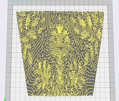
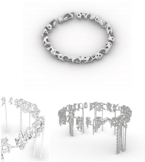
2.2.2 TEXTURE DESIGN
2.2.1 SURFACE OPTIMIZATION
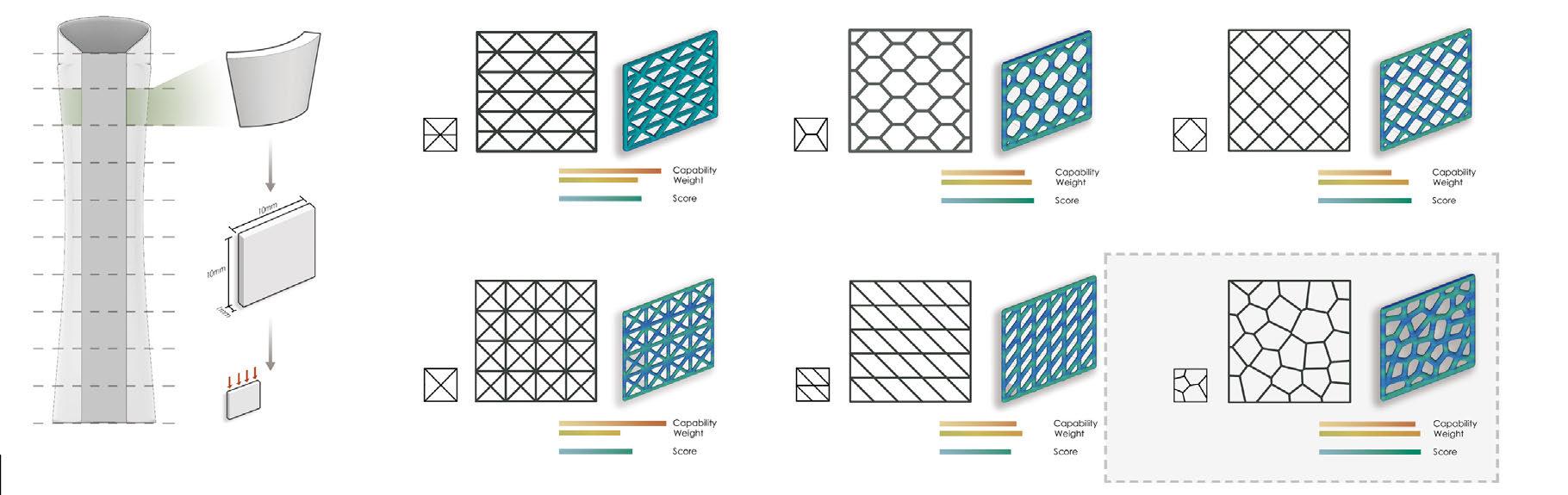
2.2.3 TEXTURE OPTIMIZATION
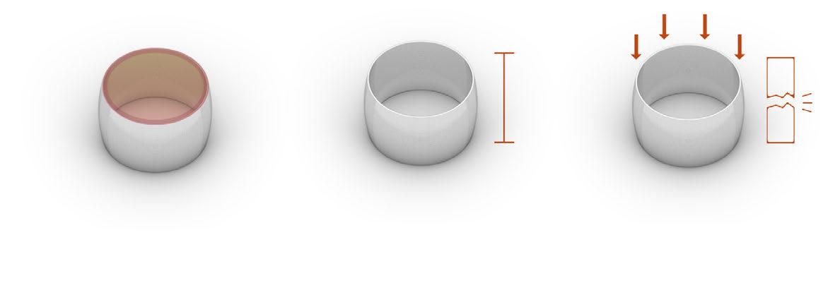
Material: Concrete Mass Density: 2500 Young's Modulus: 32500 Poisson Ratio: 0.2 Volumn Fraction: 0.4
Score = G -2/3·F G: Self Weight Maximum Load Triangle Truss Crossing Truss Hexagonal Truss Quadriateral Truss Voronoi Truss Rectangle Truss Envelope Unrolled Surface Reinforcement Staircase Trimed Surface Adjust Distribution Surface Pattern
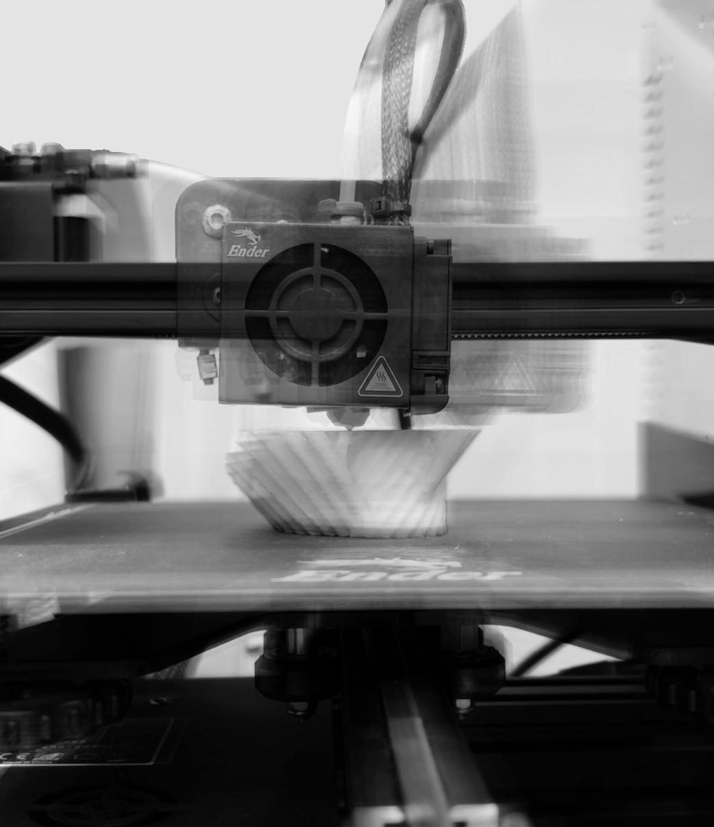
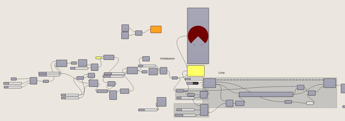
Digital Model Slicing and Path Monitoring Print Experiment Input Model Output Gcode
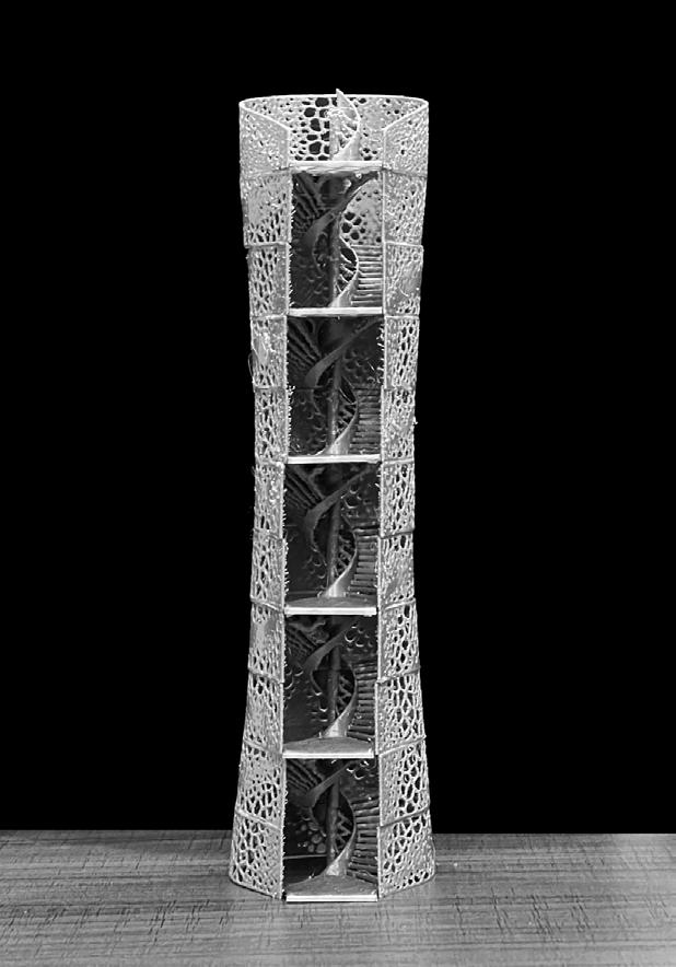
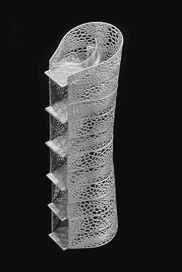
MODEL
4 5
STEP
1:10
EXTENTION OF HANDS
RESEARCH ON DIGITAL FABRICATION AND HUMAN-MACHINE
INTERACTION BASED ON SIX-AXIS DESKTOP ROBOTIC ARM
Type: Independent Study, Individual Work
Source: Studio Alpha Open Project 208
Instructor: Teng Teng
Date: 07/2022-09/2022
SLICE MODEL PRINTING 1:50 SLICING TO LAYERS 1800mm 19600mm Slice into PIeces SECTION 1:50
6 7
1.1 EXTENTION OF ARCHITECTS' HANDS
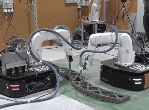
In the current era of digitalization, virtualization and automation, the construction mode of buildings is facing a huge change, and the application of robotic arms in construction is developed as a result. The operating principle of the robotic arm comes from the abstraction of the human arm, where the joint activities of the arm are reproduced in the robotic arm through mechanical structures and motors, and can therefore be controlled and operated intuitively.

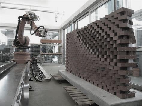
1.2 ARCHITECTURAL APPLICATION OF ROBOTIC ARM
One of the main advantages of industrial robotic arms is their versatility to support a wide range of applications in various construction scenarios. From the simplest to the most complex jobs, robotic arms are capable of handling many mechanized tasks. Through the collaboration between multiple aspects of mechanics, digital modeling and programming, the robotic arm not only allows designers to control the robot using programs that are already widely used in the construction industry, but also to digitally simulate the actual manufacturing process.


Robotic
1.2 INSPIRATION
Kinetic installation art, a branch of installation art, uses electronic technology or combines mechanical technology and uses these technical elements as an artistic language to express the artist's ideas through the artist's creations. In the late 20th century, the possibilities of kinetic architecture increased rapidly due to the rapid advances in mechanical and electronic technology.
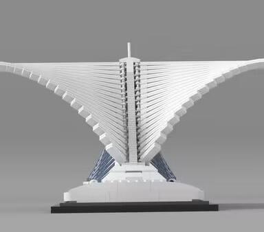
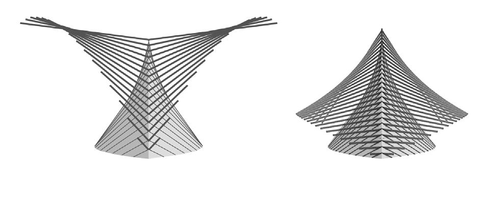
The ability of a building to move helped to enhance its aesthetic qualities, to respond to environmental conditions, or to perform functions that could not be achieved by a static structure. A more typical case is the architectural work of architect Santiago Calatrava, whose work breaks with the structural forms of traditional architecture to create unique architectural forms in a kinetic, sculptural form.
Power
Architecture Kinetic Structure
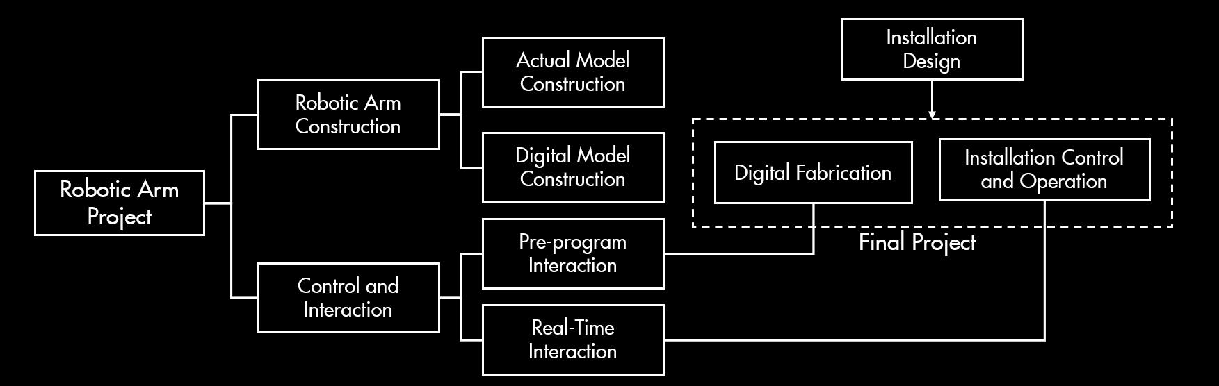
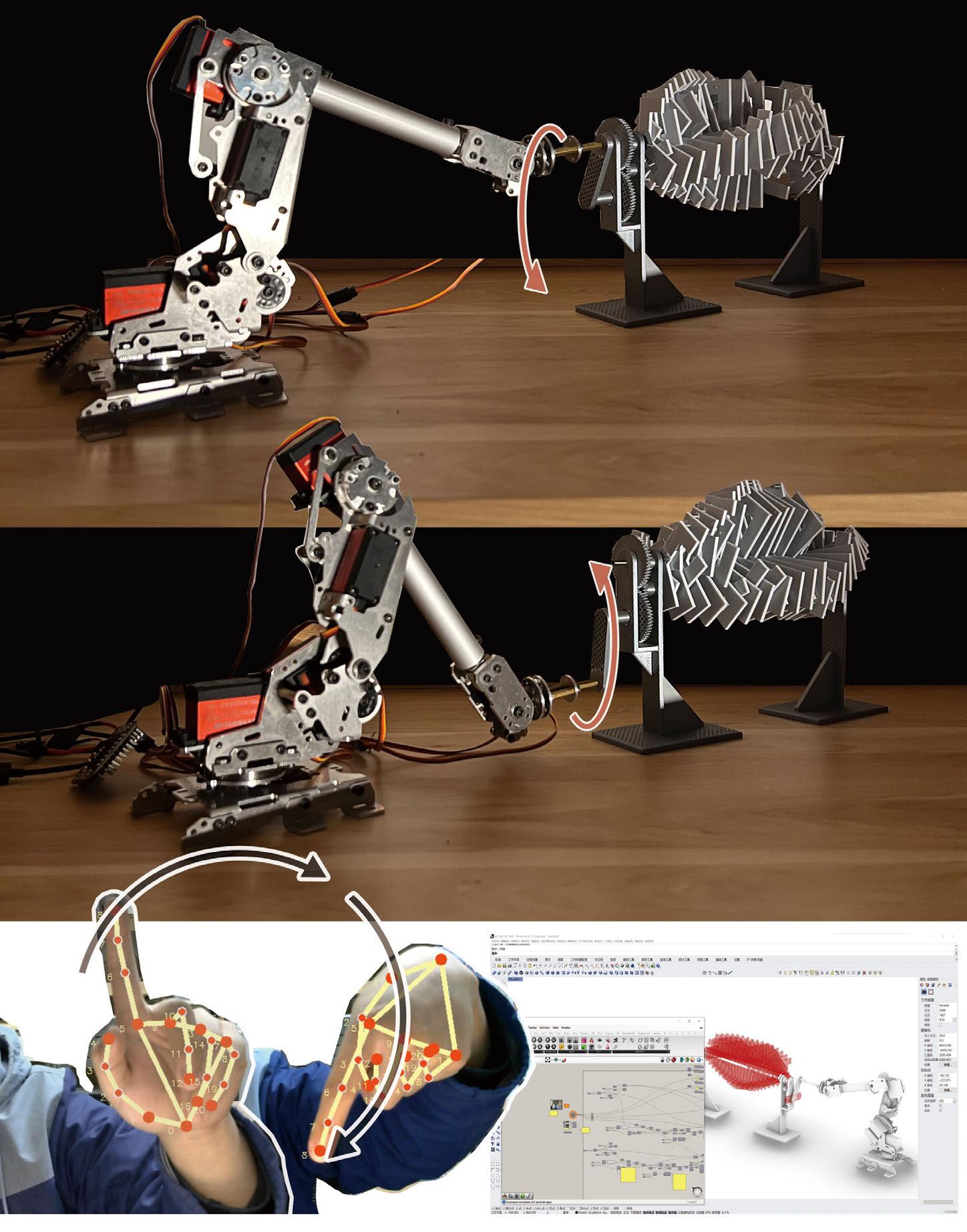
Therefore, when considering the use of a robotic arm for construction practice, it was natural for me to think of this type of form an installation piece that is digitally built and powered. Here, have divided the work into two parts: the first step is to use the robotic arm to process the components. In the second step, the robotic arm is used as a power source to feed information into the installation. These two steps also demonstrate the basic ways in which robotic arms can be used in architecture: digital processing and Human-machine interaction.
1.3 PROJECT CONCEPT
PART2 ROBOTIC ARM CONSTRUCTION
2.1 GENERAL INTRODUCTION
6-axis robotic arm is the most common type of robotic arm in practical applications, also called six degrees of freedom. In simple terms, a robot arm having six points around which motion can occur leads to the ability for the gripper to reach anywhere inside the total working radius and reach any point with the end-effector at any orientation.
Inverse kinematics refers to the reverse process. Given a desired location for the tip of the robotic arm, what should the angles of the joints be so as to locate the tip of the arm at the desired location. It calculates the angles of joints, angles of the servo motors on a robotic arm, that will cause the end effector of a robotic arm to reach some desired position (x, y, z) in 3D space.
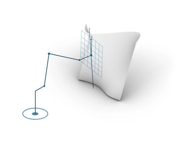
2.2 INVERSE KINEMATIC SYSTEM
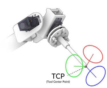
Base Point
TCP/Operation Point
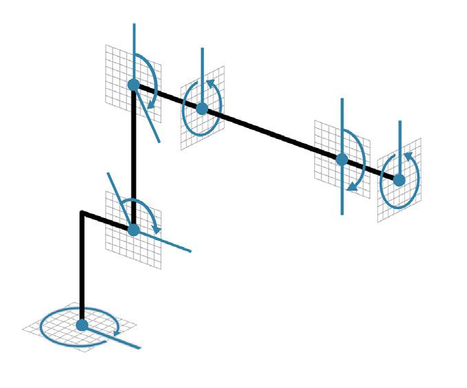
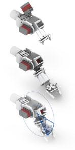
Abstract kinematic Model
The two most important points in the operation mode of the robot arm and the establishment of the digital model are the base point of the robot arm and the tool center point.
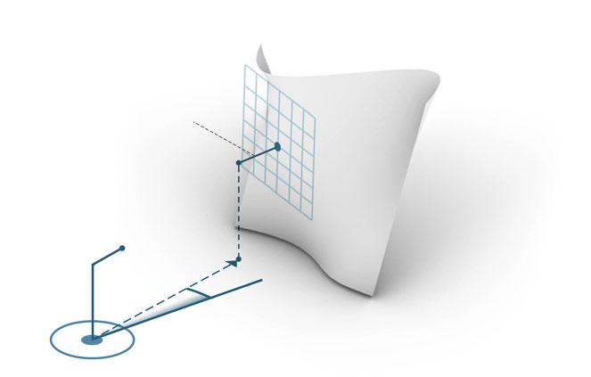
The first axis of the robotic arm is determined by the TCP's projection on the base plane and the base point. The vector direction of the line connecting the two points is the direction of the first axis.
Select the higher position of the two intersection points of the two circles as the intersection point of the upper and lower arms. The angle between the base point and the lower arm is the second axis angle, and the angle between the lower arm and the upper arm is the third axis angle.
2.3 6-AXIS ROBOTIC ARM CONSTRUCTION
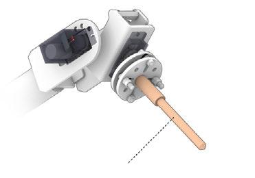
End Effector
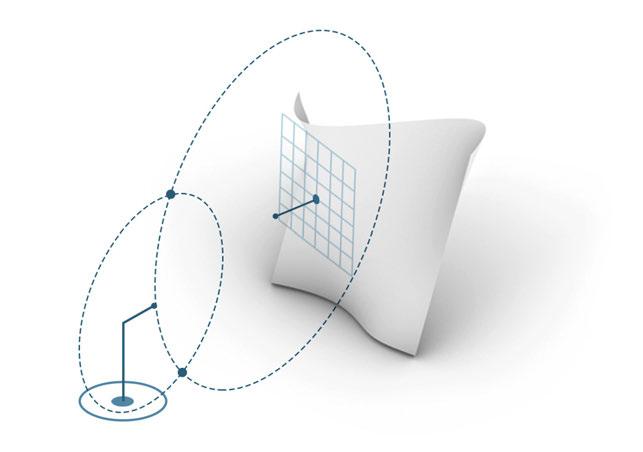
According to the base point of the and the starting point of the end effector as the center of the circle, and the lower arm and the upper arm as the radius to make a circle, the movement mode of the upper arm and the lower arm can be obtained.
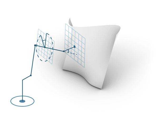
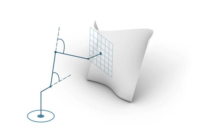
The position of each part of the robotic arm has been determined, the fourth axis is determined by the rotation angle of the upper arm, and the fifth axis is determined by the angle between the upper arm and the end effctor.
3rd Axis Servo 4
2nd Axis Servo 2&3
1st Axis Servo 1
6-Axis Robotic Arm
5th Axis Servo
6th Axis Servo 7
4th Axis Servo 5
Tangent direction of the surface
The sixth axis varies according to the function and operation of the end effector, and is also affected by the curvature of the operation plane.
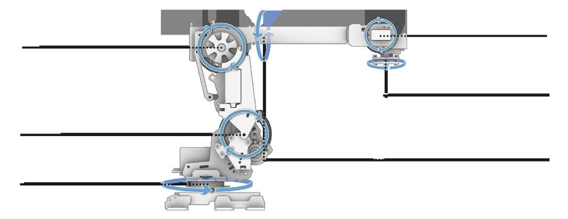
2.4 ASSEMBLE AND INSTALL 1st Axis
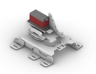
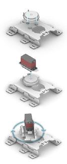
This axis, located at the robot base, allows the robot to rotate from left to right. This sweeping motion extends the work area to include the area on either side and behind the arm.
2nd Axis

This axis allows the lower arm of the robot to extend forward and backward. is the axis powering the movement of the entire lower arm.
3rd Axis
The axis extends the robot's vertical reach. It allows the upper arm to raise and lower. This axis gives the upper arm the better part access.
4th Axis
Known as the wrist roll, it rotates the upper arm in a circular motion moving parts between horizontal to vertical orientations, aiding in the positioning of the end effector.
5th Axis
This axis allows the wrist of the robot arm to tilt up and down. This axis is responsible for the pitch and yaw motion.
6th Axis
The axis extends the robot's vertical reach. allows the upper arm to raise and lower. This axis gives the upper arm the better part access.
1st Axis
End Effector Radius = Length of Lower Arm
Radius = Length of Lower Arm
2nd Axis
Axis
Axis
3rd Axis 5th
4th
6th Axis
Machinery PART I DESIGN BACKGROUND AND CONCEPT
Arm Application
8 9
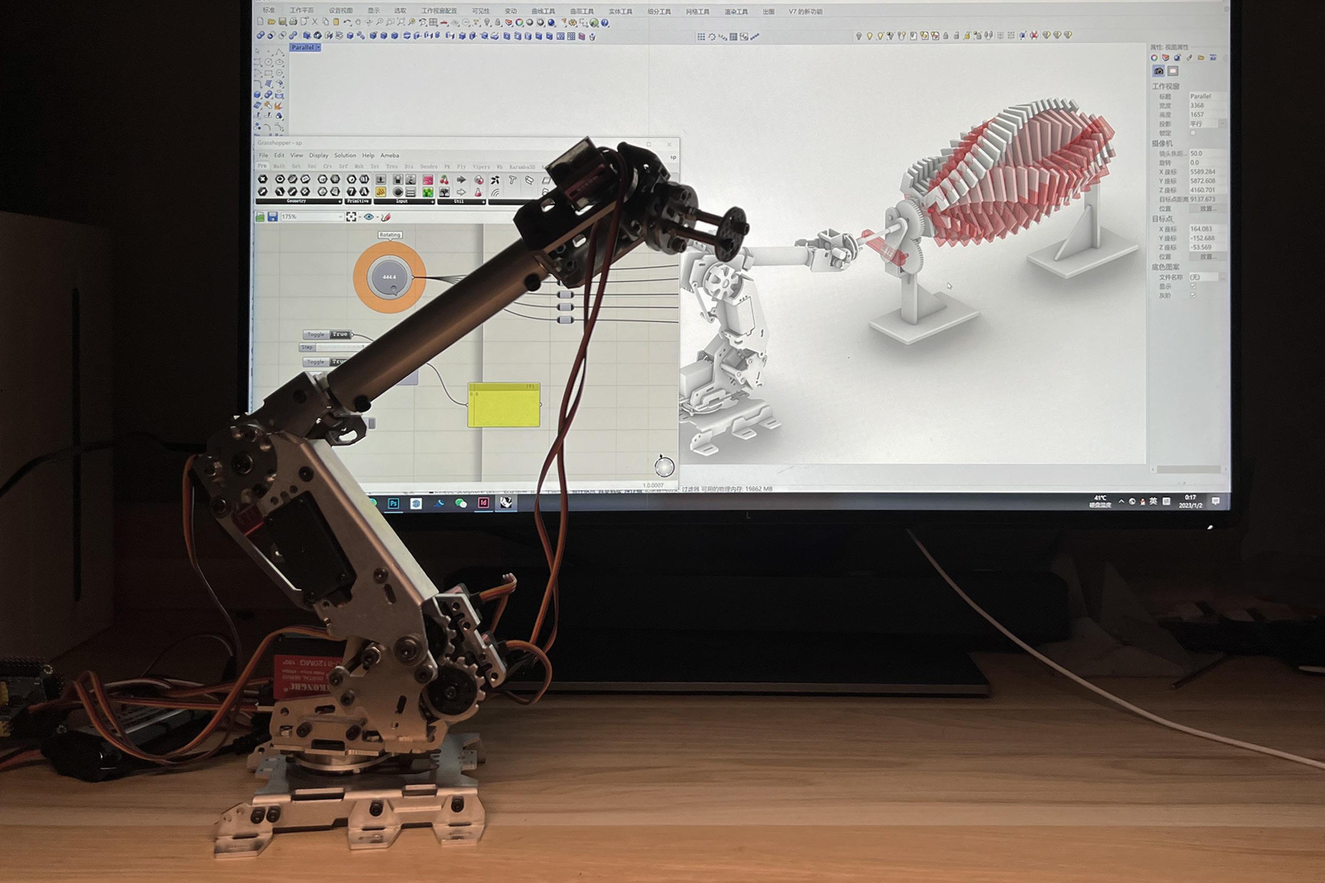
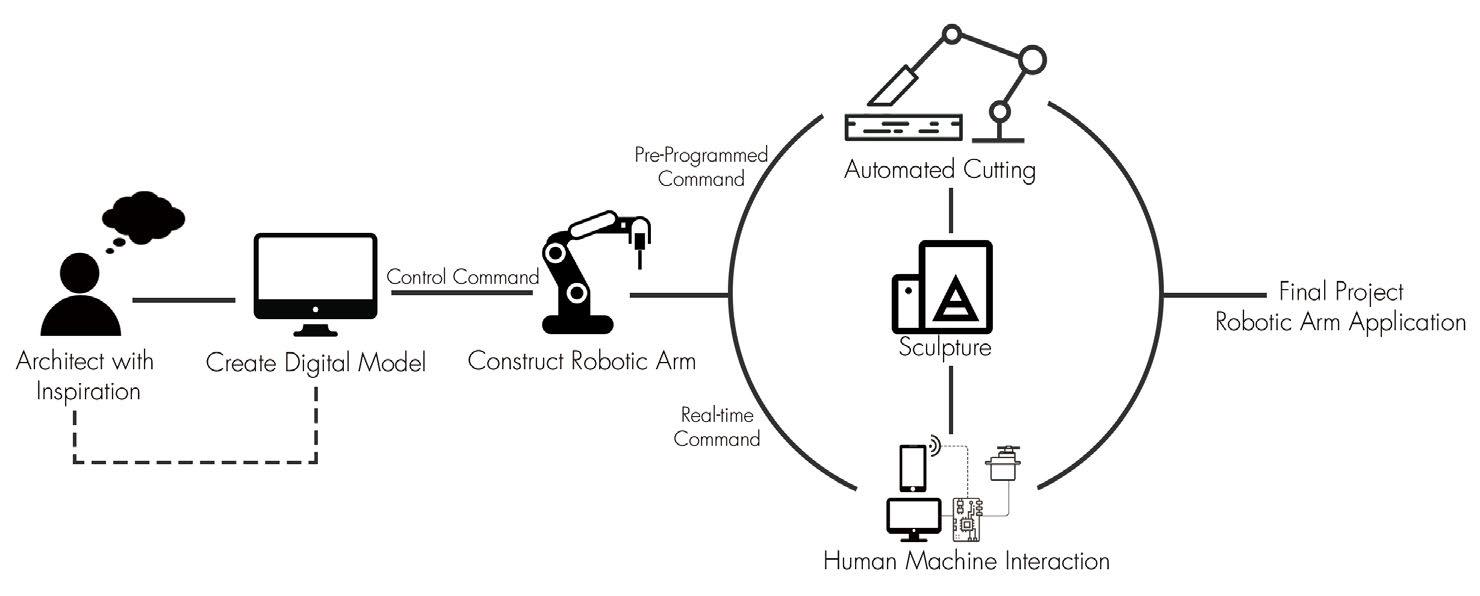
In this project, want to show an application of desktop robotic arm. Through the creation of a digital model, was able to operate the desktop robotic arm to perform processing such as cutting in order to avoid the time-consuming and laborious manual processing. At the same time, by inputting commands in the digital model, was able to interact with the robotic arm so that the final product became generated by digital processing and could be interacted with in real time, demonstrating the basic way of using robotic arms in the construction field: digital processing and interactive control.
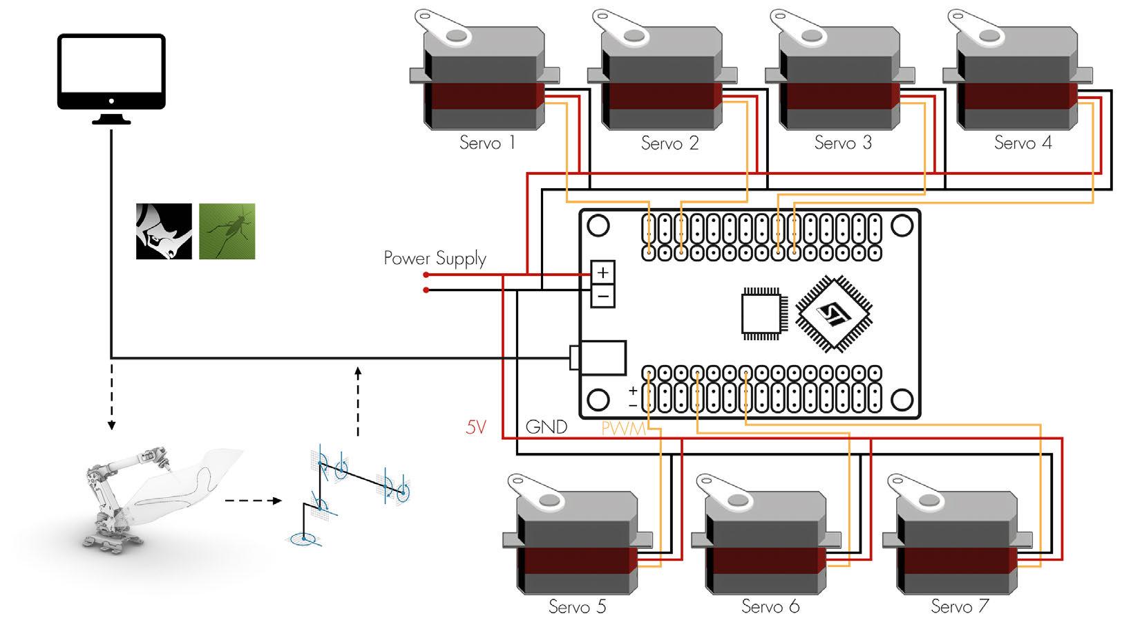
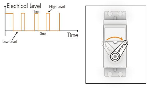
2.5 CONTROL PRINCIPLE
The next step after building the digital model is to control the robot arm. The main control process of the arm is to send the commands generated by the operation of the digital model to the servo control board, which in turn sends the commands to the servo to control the movement of the axis of the arm.
This control process can be real-time or pre-programmed, and the two types of control correspond to different application scenarios. Real-time control is used to interact with the robot arm in real time, facilitating research in human-computer interaction. The pre-programmed control method, on the other hand, can be used for digital construction, by recording the instructions of the digital model and passing the complete instructions to the robot arm at once, thereby enabling repeated processing.

Sensor
Collect Information and Convert it into Signals
Operators
Receive Signals and Send Command
Actuator
Receive Commands and Operate Servos
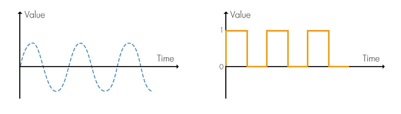
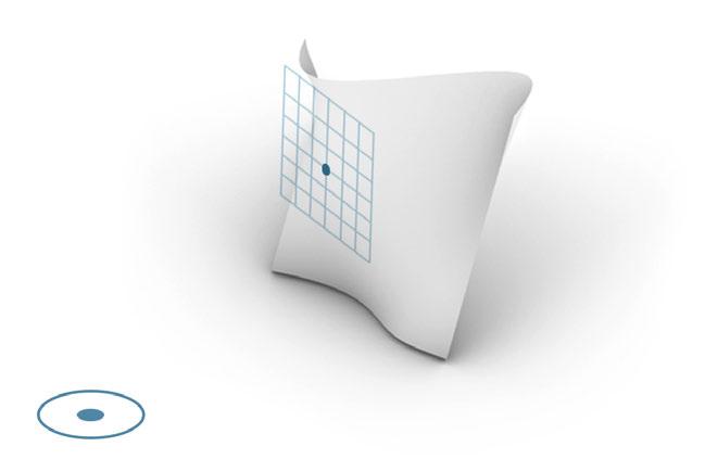
Analog Signal
Analog signal is a continuous signal in which one timevarying quantity represents another time-based variable.
2.6 SERVO CONTROL
Get Robotic Arm's Position using Digital Model
Send Command
PART 3 FABRICATION DESIGN
3.2 FABRICATION CONCEPT
Obtain the rotation angle of each servo according to the inverse kinematic model
#1P1611#2P1722#3P1278#4P1667
#5P1500#6P1111#7P1500T100/r/n
#1P1689#2P1589#3P1411#4P1833
#5P1500#6P1078#7P1500T100/r/n
#1P1333#2P1656#3P1344#4P1756
#5P1500#6P1089#7P1500T100/r/n
#1P1544#2P1778#3P1222#4P1600

Build digital models for further operation
3.3 DESIGN DETAIL
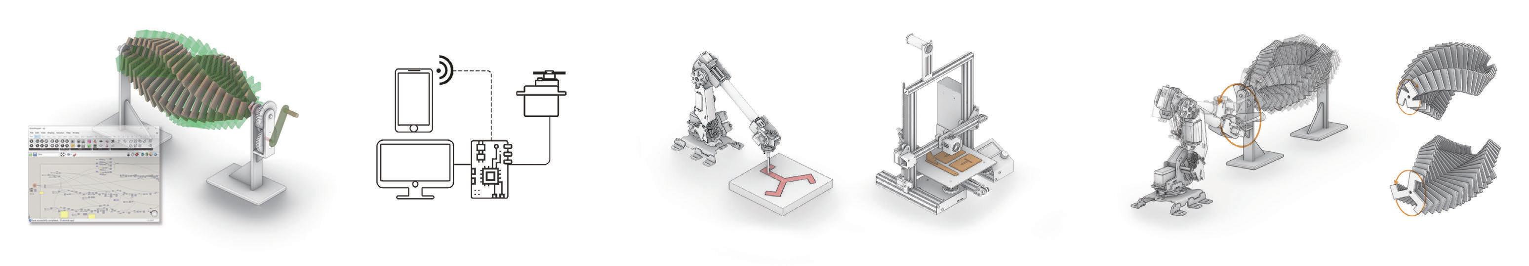
Paddles
Obtain command information based on the digital model and send it to the servo Fabrication Process
Robotic Are Cut Paddles 3D-Print Base Support
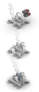
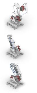
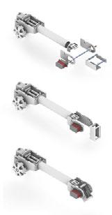
Enter real-time or preset commands to operate the installation movement using the robotic arm.
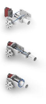
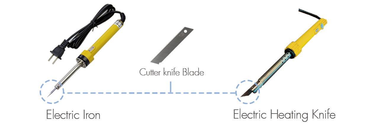
3.3 END EFFECTOR DESIGN
STEP 1
Considering the material that will be used, the use of electric heating cutting is a better way to go. therefore modified a electric iron by adding a blade to its top, making it a knife with electric heating function.
Digital Signal Original
real number within a constant range of values.
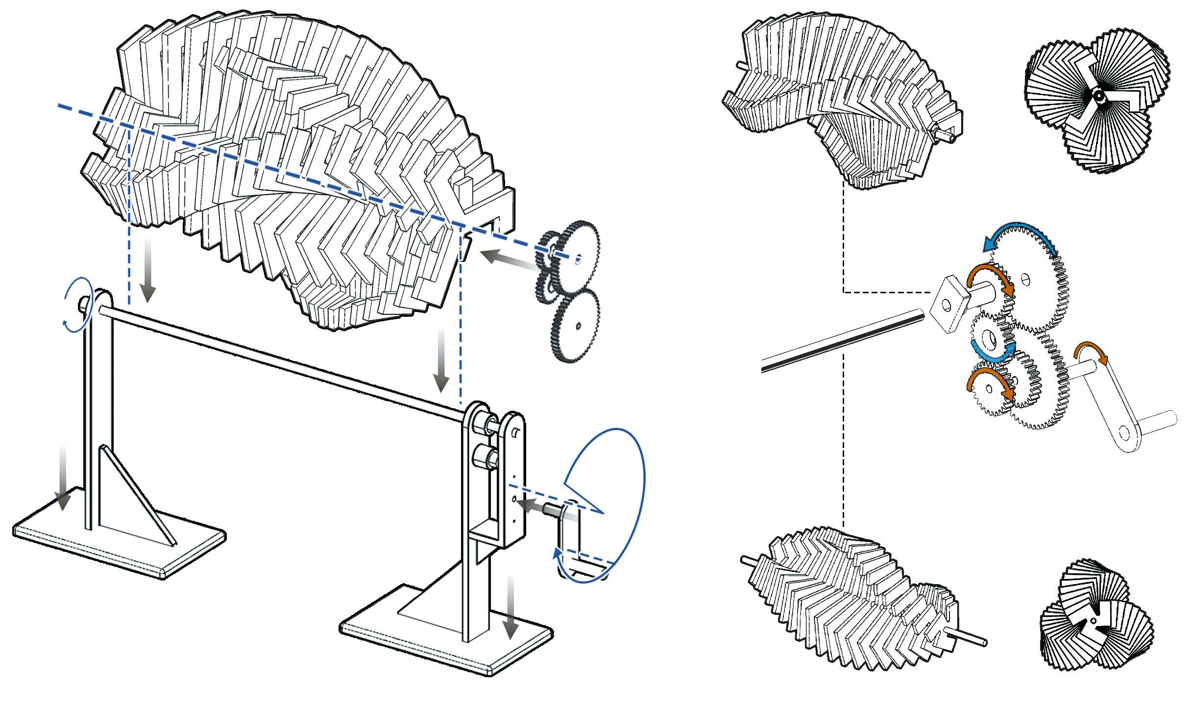
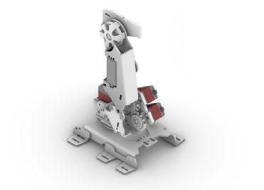
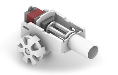
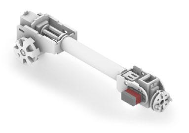
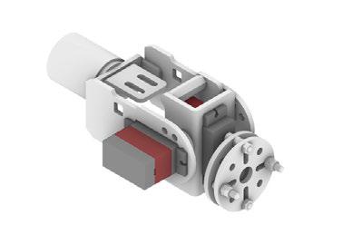
Gear Set
Rotating Axis
Counterclockwise Rotation
First Set of Paddles
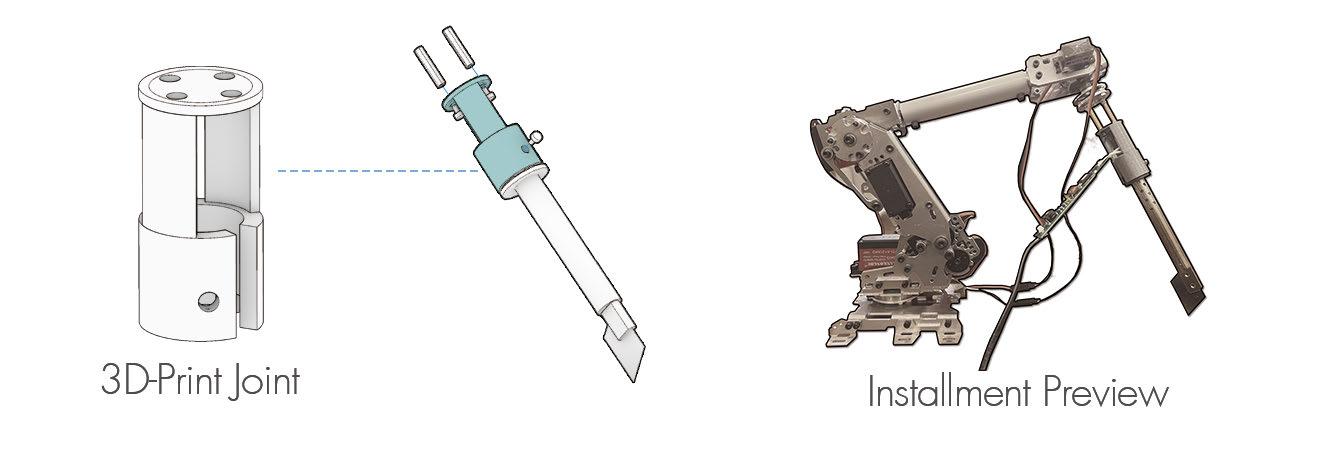
STEP 2
Clockwise Rotation
Second Set of Paddles
After the modification is completed, the electric heating knife needs to be installed on the last axis of the robot arm as an end-effector. Here designed a part for mounting the two together and used 3D printing to fabricate such a part.
Crank
Base Support
Through the crank input power, make the gear set to produce clockwise and counterclockwise two directional rotation angle, drive the two groups of blade rotation
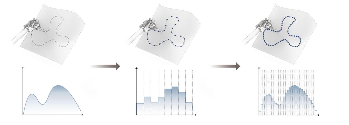
A digital signal is a signal that is used to represent data as a sequence of separate valuesat any point in time. This type of signal represents a
Signal Sample Resample
Axis 1 Axis 2 Axis 3 Axis 4 Axis 5 Axis
Servo
Servo
Servo
Servo
Servo
Servo 6 Servo 7 Angle 1 Angle 2 Angle 3 Angle 4 Angle 5 Angle 6 Angle 7
6
1
2
3
4
5
#5P1500#6P1122#7P1500T100/r/n 0.5ms 1.0ms 1.5ms 2.0ms 2.5ms 0° 45° 90° 135° 180° 10 11
In the previous process, the robotic arm assisted in the digital processing by pre-programmed instructions. And the next step is to use the robotic arm as a power source through real-time control to achieve the movement and interaction of the power unit.
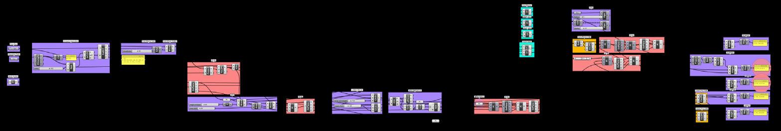
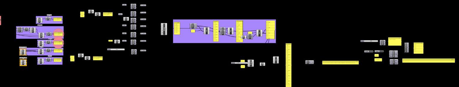
obtained my hand position data through gesture recognition tool sucha as Mediapipe and passed this data into the digital model so that it could issue commands to the servo control version in real time based on my hand motion, enabling real-time human-robot interaction
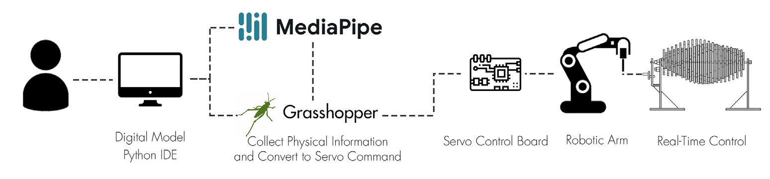
Since the python editor that comes with grasshopper is too single-featured to satisfy the function of entering location information via mediapipe. Therefore, cross-platform data transfer will be useful in solving this issue. In the client-server model, python IDE will be the server to provide the data, and the Grasshopper will be the client that receive the data. In Python, we can use the built-in library socket to achieve it.
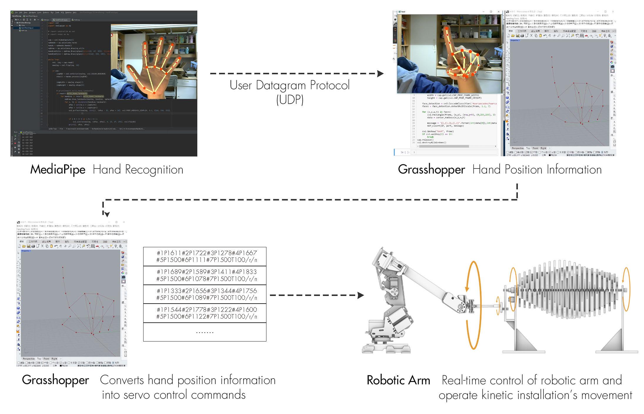
4.2 CONTROL PROCESS

LIVING AS YOU WANT
AN ATTEMPT OF DESIGN DEMOCRATIZATION
BASED ON COMPUTATIONAL TOOLS
Type: Academic Work, Collaborative Work
Collabrator: Collaborated with Wang Jiayue in 2022.4 individually refined in 2022.11
Contribution: Concept Design, Coding, Drawing.
Instructor: Li Biao
Date: 02/2022-04/2022
13
PART 4 CONTROL AND OPERATION 12 4.1 REAL-TIME CONTROL
1.1 DISAPPEARING VOICES
In the past century, as more than 800 million people moving from rural to urban areas in China, the question of how to provide housing for a rapidly growing urban population is one that the government must address. One of the most important measures is to provide pooled housing that is built uniformly and distributed free of charge or at low cost.
However, there are two sides for everything. Under the practice of market economy reform, ordinary housing tends to be homogenized and people are more and more lacking the possibility to make choices. The price growth of commercial housing has led to an oversupply of low-priced pool housing, and the quality of housing has also created an increasingly large gap with commercial housing.
At the same time, neighborhoods, once part of China's residential culture, are fading fast. From the coexistence of traditional agricultural societies based on blood and local ties to the planned economy, where people were dependent on state and unitary resources, the spiritual connection shaped by neighborhoods was an important attribute of social culture. But today, the rapid urbanization and the Internet era have changed things. People have never been so close to those who are on the other side of the earth, but never so distant from those around them.
1.2 CURRENT LIVING RESEARCH


1.3 HOUSING DEMOCRACITIZATION
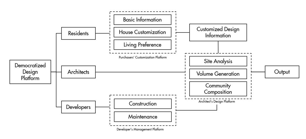
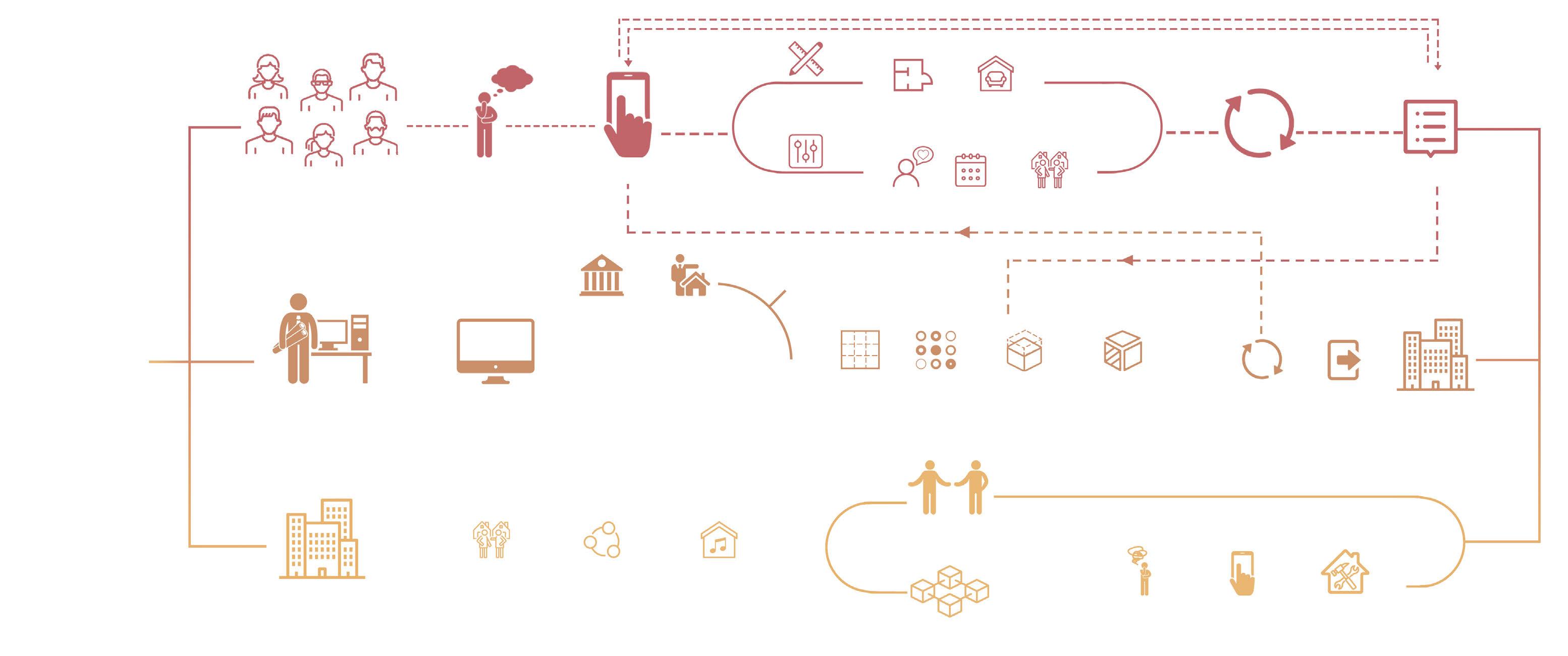
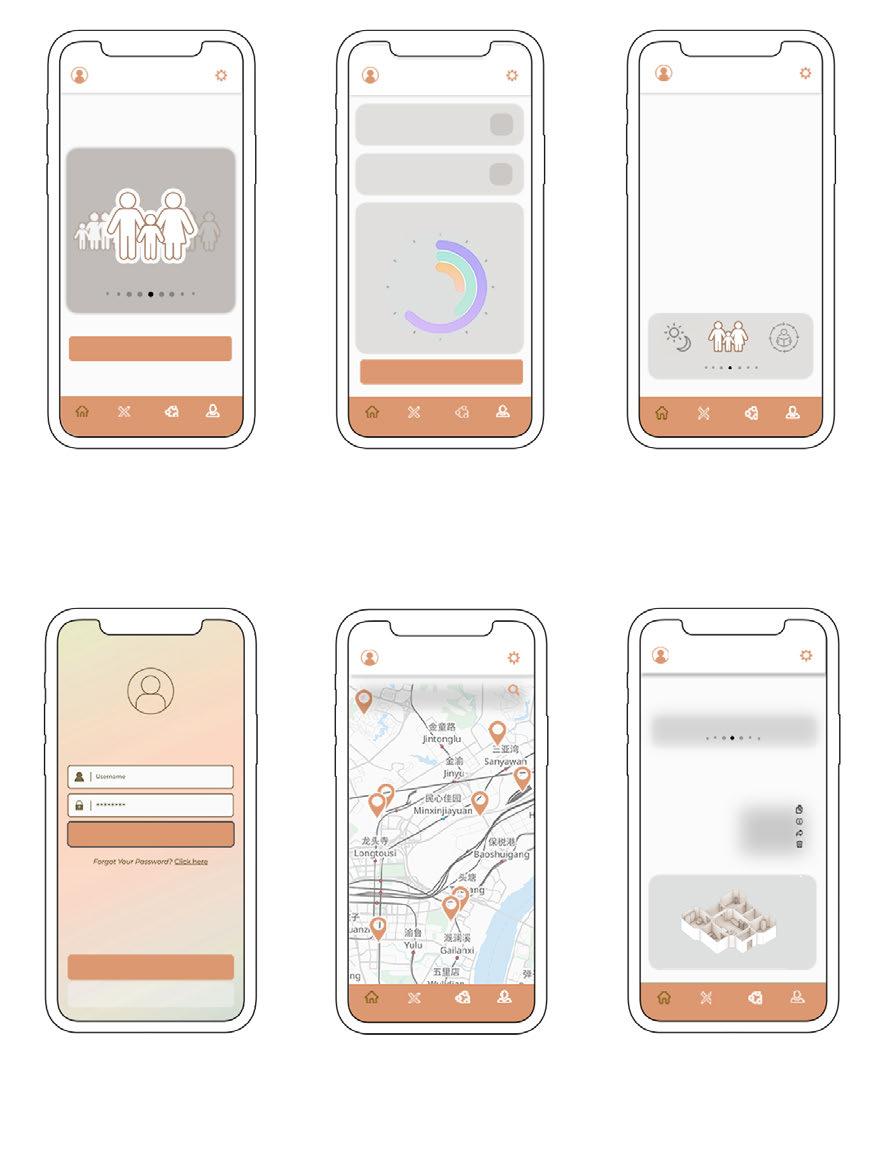
In this project, we hope to come up with a housing design platform that can be used by both the architect and the homebuyer. The homebuyer can provide information such as personal living habits and hobbies, and customize the style of the room, while the architect can quickly generate the graphic design of the house through the program, and arrange the layout of the house reasonably through the information uploaded by the user.
Computer-aided computational design methods offer this possibility intuitive, fast and adaptable. By transforming the elements of traditional architectural design into the processing of data and information, architects are able to quickly generate and select suitable solutions.
The embodiment of social culture depends on the establishment of the order of life patterns. Therefore, we hope that all people will participate in the construction of the living pattern, so that the needs of all parties can be met to the greatest extent, and the democratization of design and living can be realized
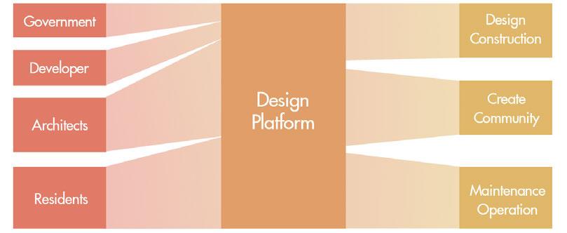
Current Developer and Architect-Led Construction Mode
The current mainstream residential construction model. The government and developers propose development needs, and architects and builders design and build the homes. In this process, the occupants are unable to make demands and have to make passive choices based on what homes are available in the market.
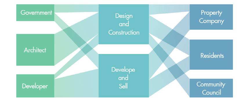
Democratized Design Mode with User Participation
We want to propose a democratized design vision in which different participants have the same status and can contribute equally to the design. In this model, the needs of the residents can be met and a good community environment created.

15
14 PART 1 DESIGN BACKGROUND AND CONCEPT
Living Condition Neighborhood Relationship Residential
Diversity
Data Resource: China Youth Daily, People's Daily
2.1 CUSTOMIZED DESIGN PLATFORM
The current residential design model led by developers and architects leaves homebuyers with only passive choices, while in this project, we want homebuyers to actively participate in the design of their homes by submitting their own house layout and decoration designs, while matching the right neighbors by filling in their preferences, personalities and living habits.
2.3.1 PLAN AND LAYOUT
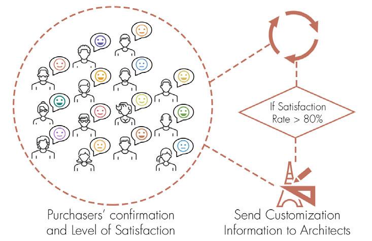
2.4.1 FEEDBACK OPTIMIZATION RESULTS TO PURCHASER
PART 3 DESIGN PLATFORM FOR ARCHITECTS
3.1 SPACE PROTOTYPE RESEARCH
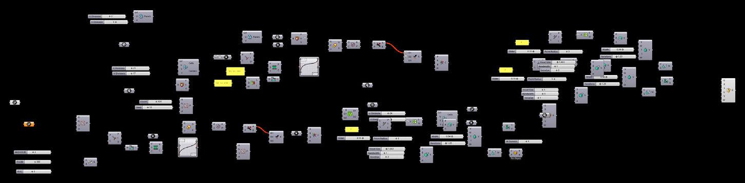
3.3 COMPUTATIONAL ARCHITECTURE GENERATION
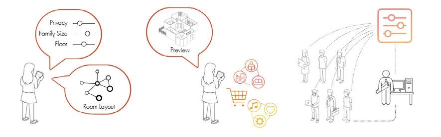
Input Customization and Preference Information
2.2 APPLICATION OPEN TO PURCHASERS
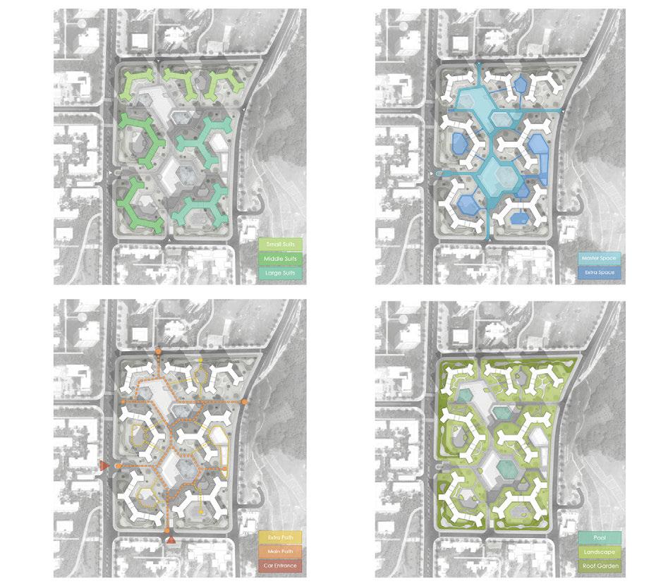
On a platform facing the use of architects, we hope to develop a method that could quickly and iteratively generate aggregate housing projects. We want to be able to study the compositional relationships and interactions of the different elements of the building in terms of topological relationships of the plane.
Collect Feedback and Cofirmation Send Design Information to Architects


Feedback and Reconfirm
2.3.2 NEIGHBORHOOD COMPOSITION

Purchasers can preview their room shape and neighborhood information in advance and give feedback on whether they are satisfied with the arrangement
2.4.2 PURCHASER CONFIRM
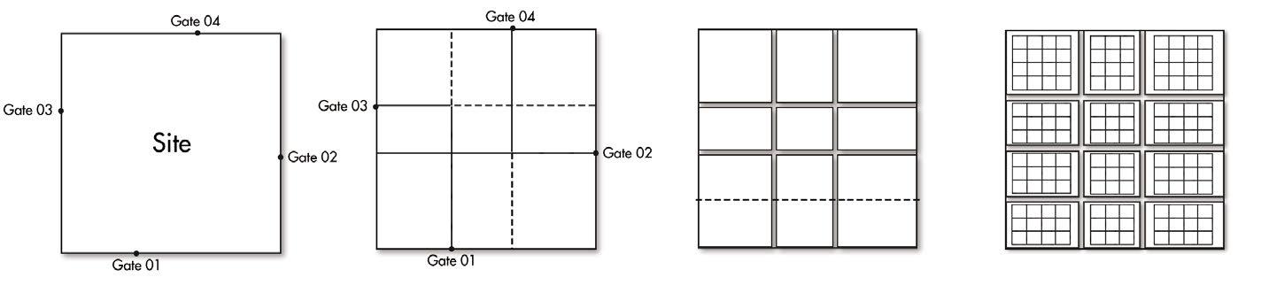
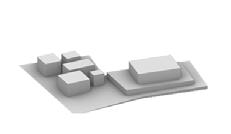
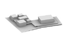
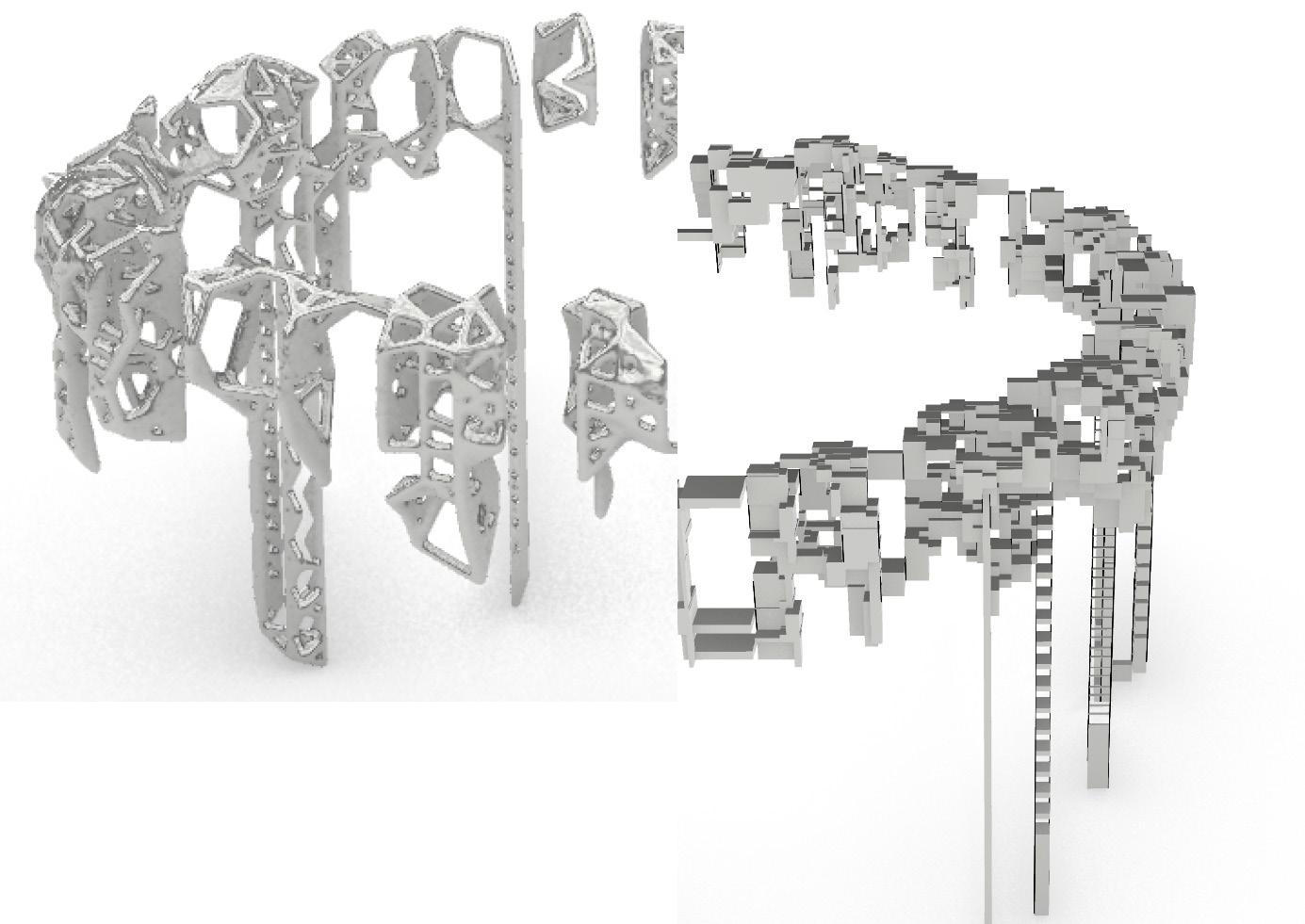
After studying existing examples of clustered housing, we believe that enhancing the connections between different buildings in a district while creating well-connected public spaces is a good means of enhancing neighborhood relationships.Based on this, we propose a method to generate building volumes based on site topological relationships. This method calculates the weights of different grid points after gridding the site, extracts the points to generate connection lines, and generates building volumes.
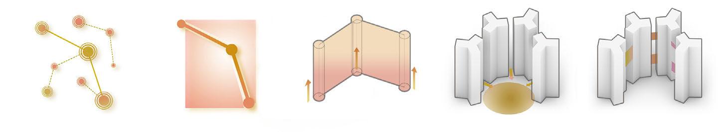
Dot—Occupation Line—Division Volume—Space Formation Enclosing the Public Space Connection
3.2 SITE PRE-PROCESSING
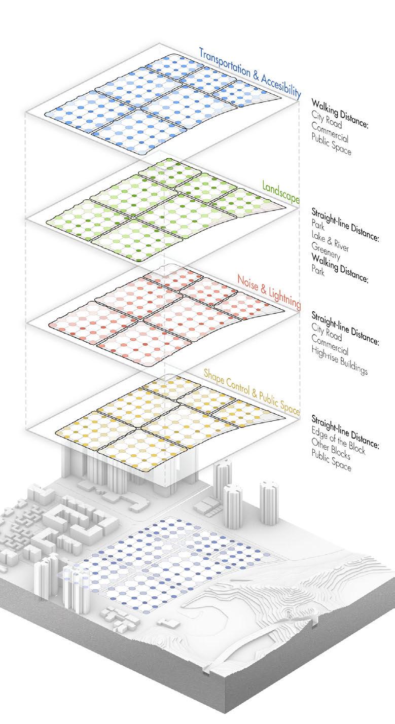
The second step is to calculate the weights of the grid points generated in the first step by inputting the environmental points of the site surroundings, and connect and generate the volume according to certain restriction rules.
Enter
Step 1
Extracting grid points
Walking Distance
Calculate the distance of the rigidpoint through the road to the target point using Dijkstra Algorithm.
Step 2
Straight-line Distance
Directly calculate the length of the line between two points.
Define distance algorithms for different elements
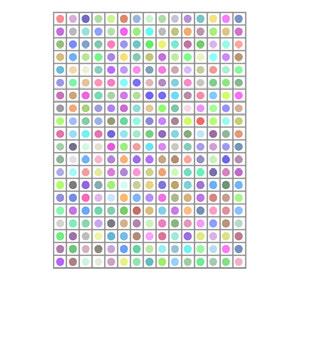
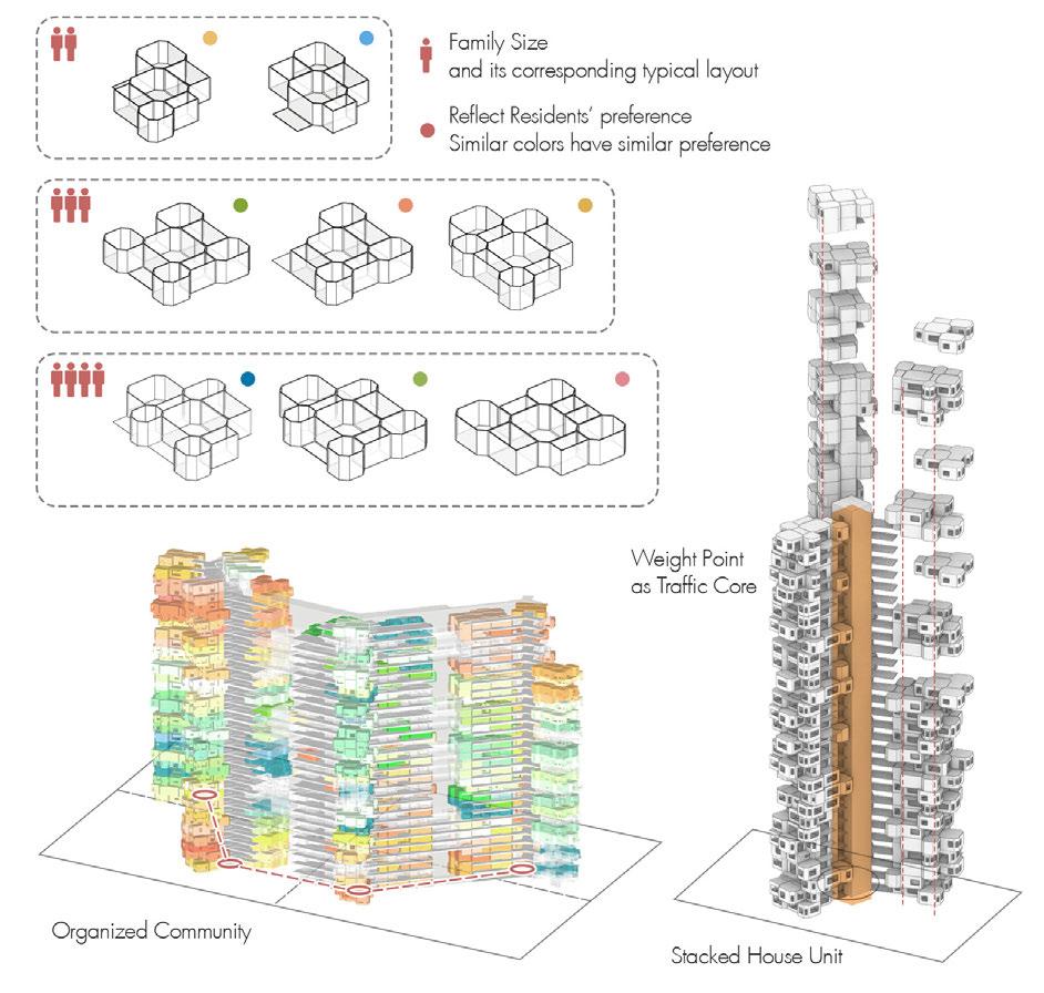
Enter personalities, hobbies, habits, etc. on the platform
Classifying users with different personalities into different types
Similarity Diversity
Unorganized Community
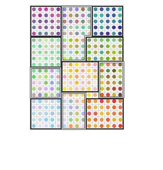
Organized Community
Similar Personalities

The first step to do is to enter the site information into the platform, including the shape and size of the site. The next step is to extract four types of elements around the site, landscape, commercial, public facilities, and other residential areas These elements will be input as POIs, which will become an important basis for generating volume afterwards.
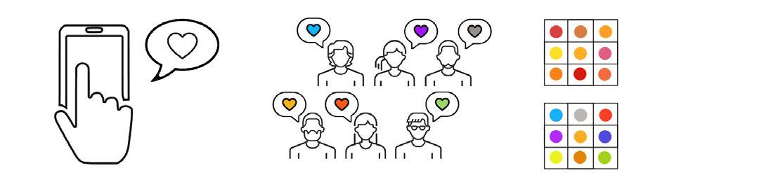
After analyzing the information provided by homebuyers, these people can be assigned to different areas based on their preferences and personalities
Different Personalities
Prefer to socialize with various people
Divided into different types of communities based on different preferences
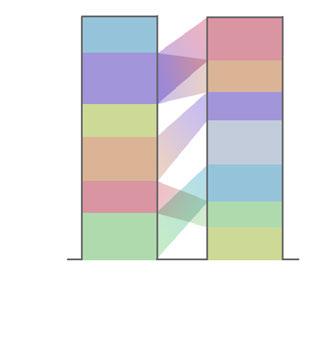
Randomly arranged neighborhoods where people do not know the hobbies and personalities like-minded
Prefer to socialize with similar people people in randomly arranged neighborhoods have difficulty meeting like-minded neighbors.
Submit customization requirements and payment
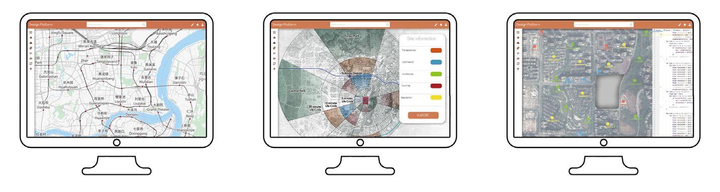
Analyze the surronding environment of the site
2.4.3 SENDING CUSTOMIZED INFORMATION TO ARCHITECTS
Extract Various types of elements of the surrondings
Input the elements as POIs into the IDE
The next step in the design is to divide the plots. First enter the site shape and dimensions into the program, and mark the entrances and exits in the site. From the entrance point, a straight line is generated inward to divide the site. Next, the larger parcels in the site are cut once more so that they do not exceed and are not smaller than a certain size.
Step 3
Calculate the weights according to the input environmental factors
Step 4
Connect points with high weight values in the block
Input the Size and shape of the site, and locate the entrances.
Make a straight line starting from the entrance to make a preliminary cut of the site
If one side of a block is longer than 120m, the side will be cut again to ensure that each block is larger than 60mx60m and smaller than 100mx100m
(3) (2) (1) (4)
Use 20mx20m grid cells to grid blocks for the next step of volume generation

tep 5
Generate volumes based on point locations and connecting lines
17 PART 2 RESIDENTS' PARTICIPATION IN DESIGN
basic information
as
Living Habits, Preferences etc.
such
Family Size,
CUSTOM NEIGHBOR PROFILE
16

3.6 ENVELOPE GENERATION
By the previous steps, the building volume is generated, and the next step is to generate the building envelope by some rules. The building generated in the previous step consists of different functions, and the different functions correspond to different rules of envelope generation.

The points extracted in the previous steps can be used as the traffic core of the residence. Meanwhile, the house layout information uploaded by the purchasers and the optimized community composition become the basis for building volume generation.
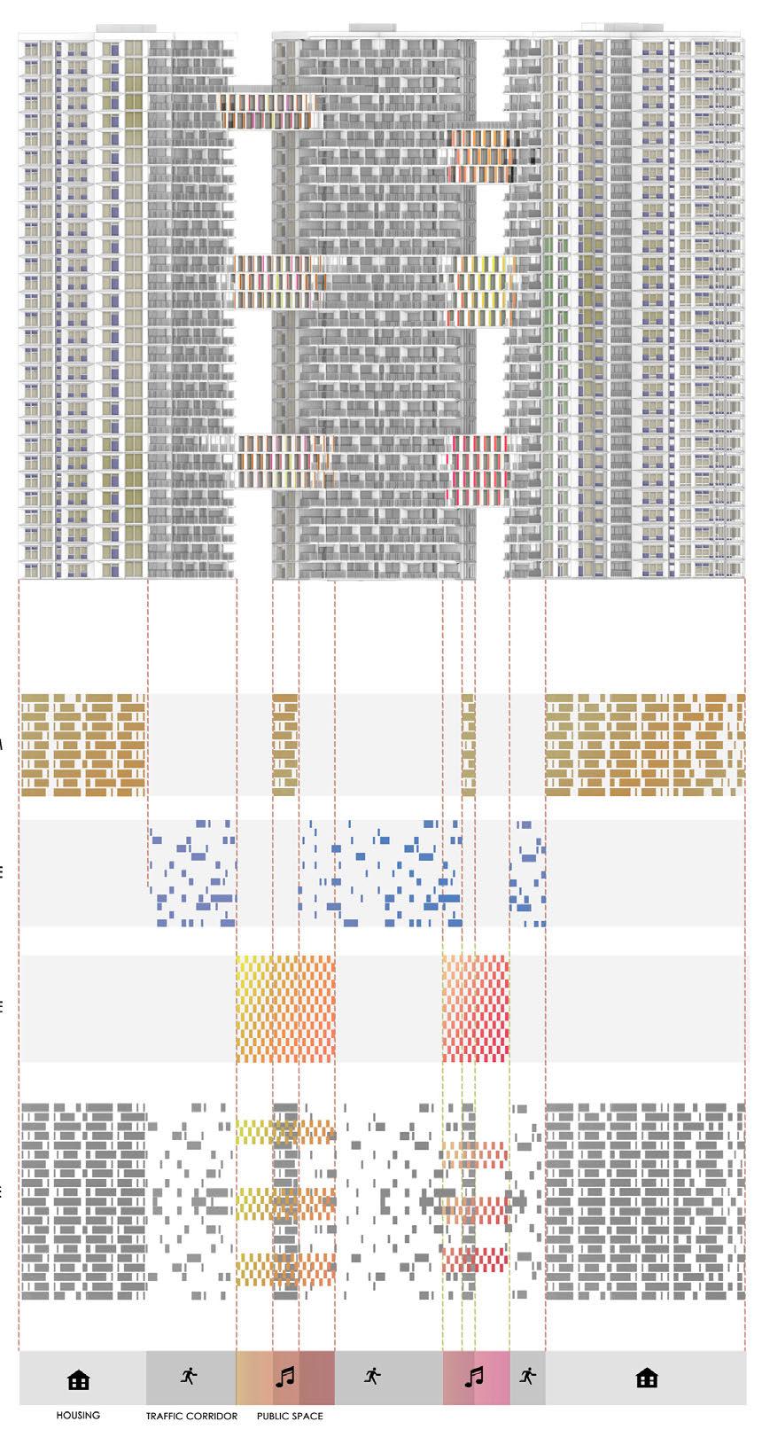
3.7 OUTDOOR AND PUBLIC SPACE GENERATION
The generated volume is offset outward as a contour on the plane, and a Boolean operation is performed with the square site to generate the roads and public spaces inside the settlement.

CYBER FAIRYTALE
3D-PRINTING HOUTE COUTURE
Type: Research, Collaborative Work
Contribution:Apparel Design, Printing Experiment, Drawing.
Instructor: Wu Lingju, Hua Hao
Date: 06/2022-07/2022
PART 1 BACKGROUND AND CONCEPT
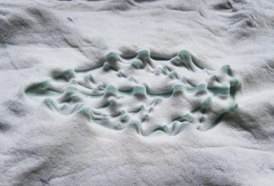
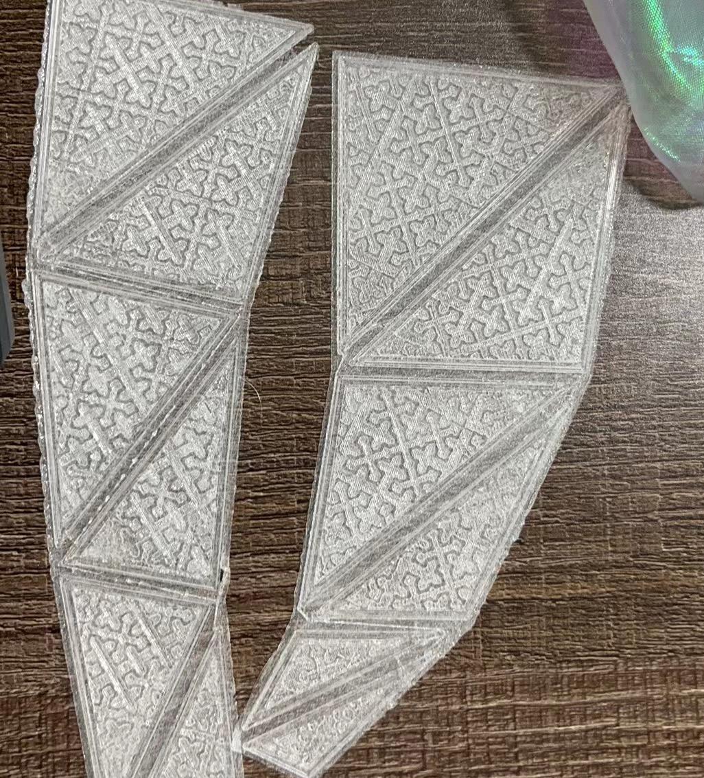
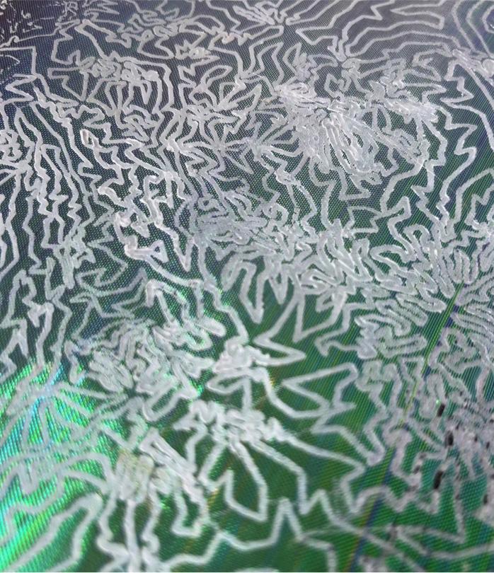
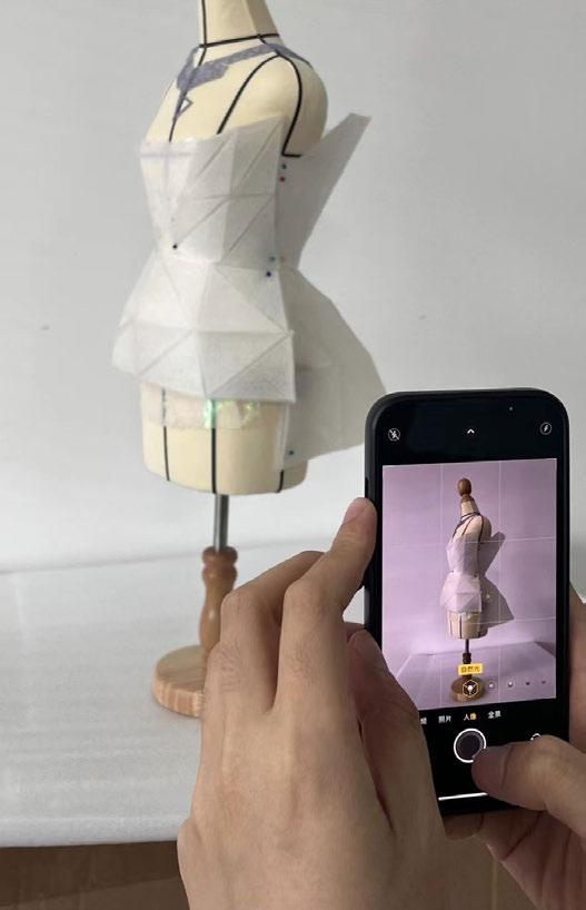
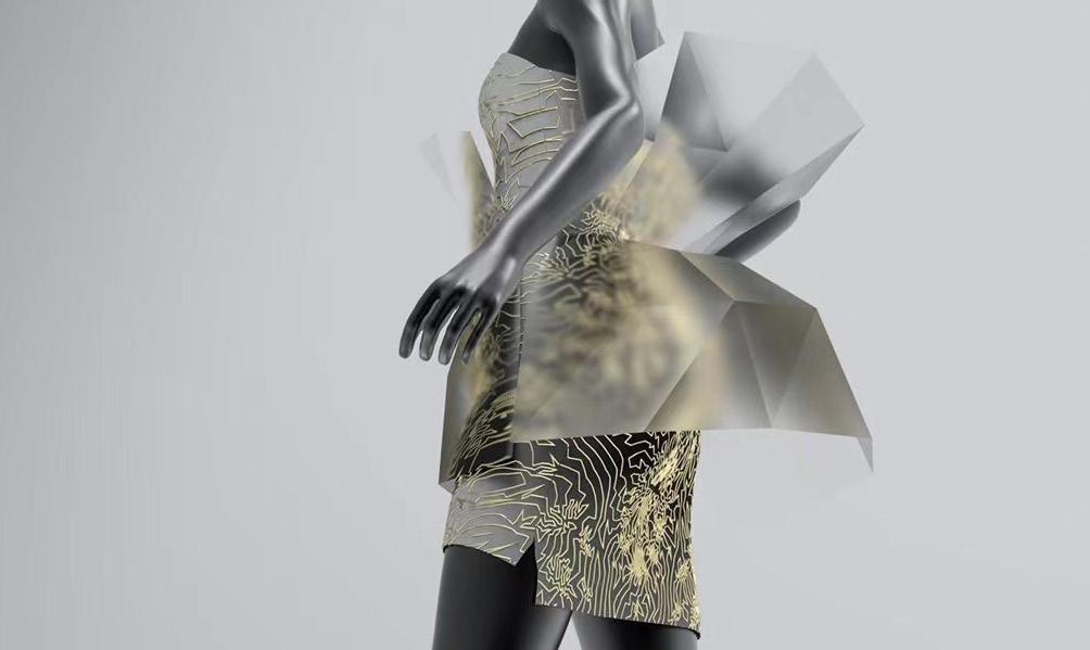
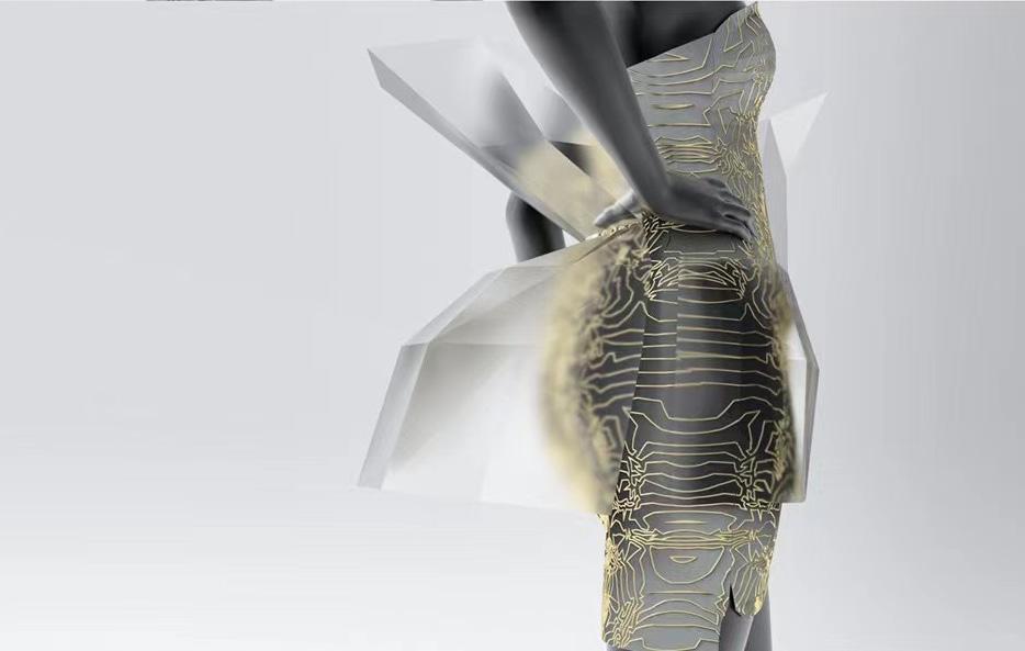
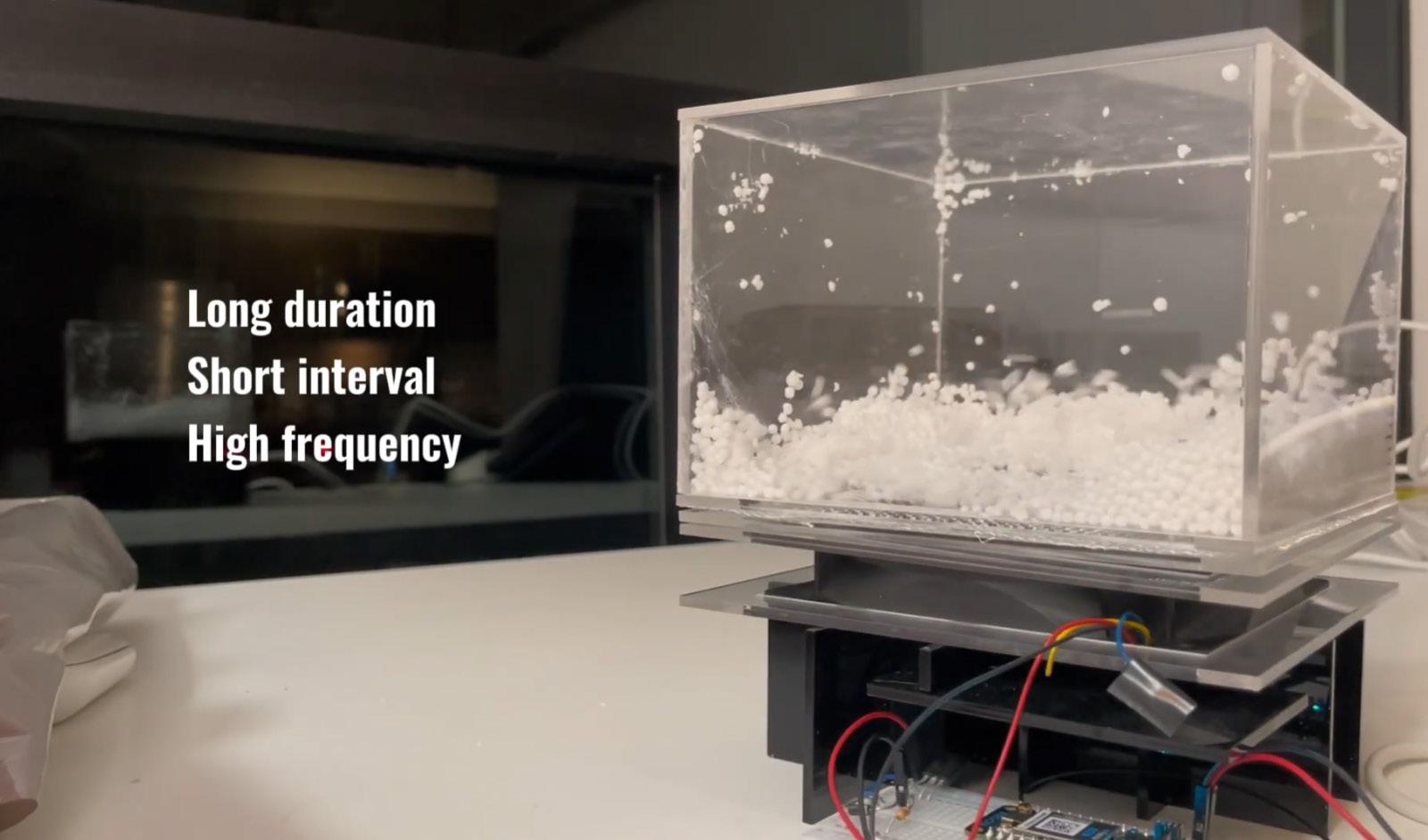
Emerging 3D printing technologies are forging unprecedented new types of fabrics, serving as a significant impetus for architects to engage in custom fashion design. Notably, the use of TPU flexible printing and FDM combined with fabric introduces novel possibilities for fashion silhouette and fabric texture. Many fabric printing experiments encounter failures or flaws, yet direct interaction with the fabric using hands or body allows for adjustments in its geometric structure or printing technique.
Designers strive to produce fabrics that meet predefined characteristics, but the iterative process of experimentation can also lead to entirely new ideas. Thus, design research and manufacturing experiments complement each other. The development of 3D fabrics based on computational design spans across architecture, fashion design, information technology, and automation technology. It also integrates cultural ethos, artistic sentiment, mathematical logic, and practical techniques. This development of 3D fabrics will become an intrinsic part of fashion design practices.
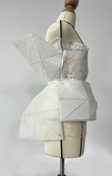
This project focuses on customized 3D printing techniques for garments, exploring how fabrics can effectively integrate with various materials to form complex self-forming mechanisms. It involves digital adjustment of the fabric's texture, performance, and appearance, innovating fashion design through customized processes.
18 3.4 OPERATION RESULTS AND OUTPUT
3.5 VOLUME GENERATION
Original Output Final Output
Shape Constraints
Add
3.8
OUTPUT FINAL RESULT
Grille Facade
Winsows of House Corridor Grille Public Spave
19
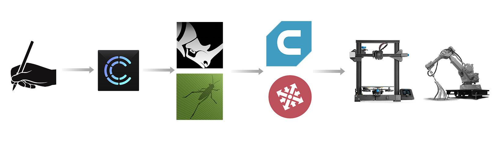
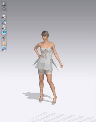
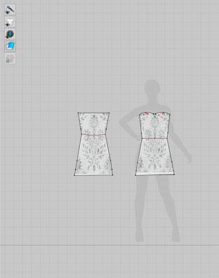
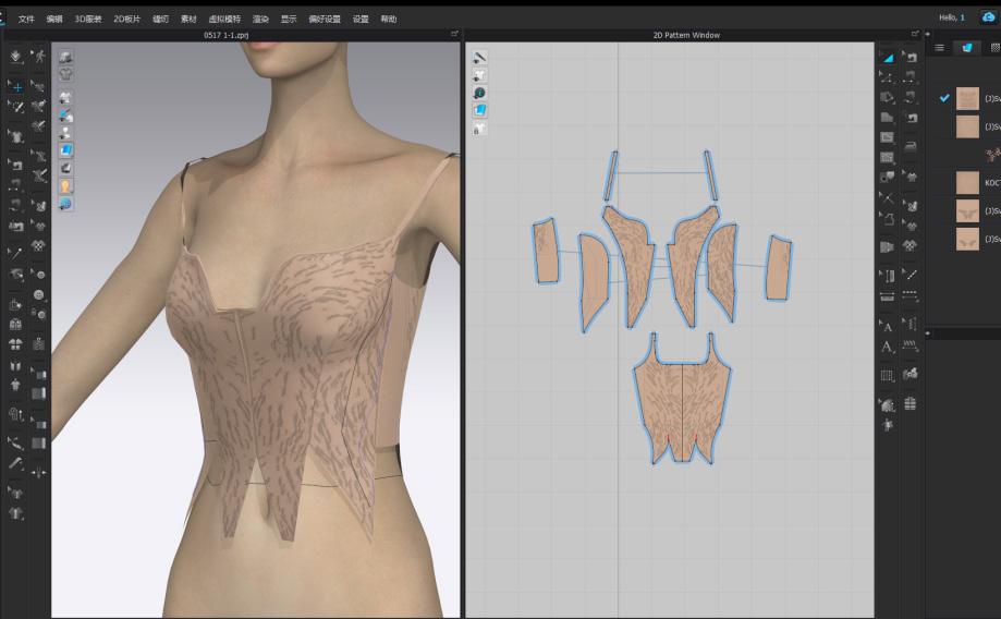
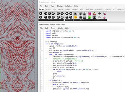
The team first used CLO3D for paneling and styling after conceptualizing the design. The pattern and fabric models were then imported into Rhino and parameterized using Grasshopper to create the digital model. The digital model was then sliced and printed.

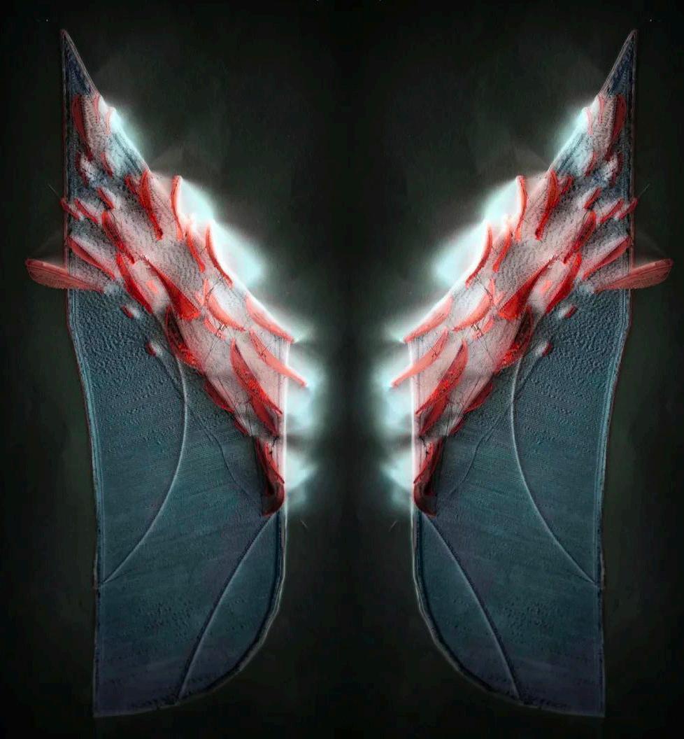
PART 3 DESIGN OUTPUT
3.1 PRINTING EXPERINMENT
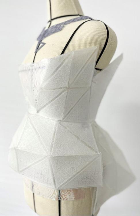
3.2 RENDERING DISPLAY

PART 2 DESIGN PROCESS
DESIGN WORKFLOW 20
2.1
EXPERINMENT CLO 3D Pattern Making/Layout Design Slicing and Path Monitoring Concept Design Rhino & Grasshopper Digital Modelling Printing & Fabrication
2.2 PRINTING
Style and Layout Design Digital Modeling Prepare for Printing
21
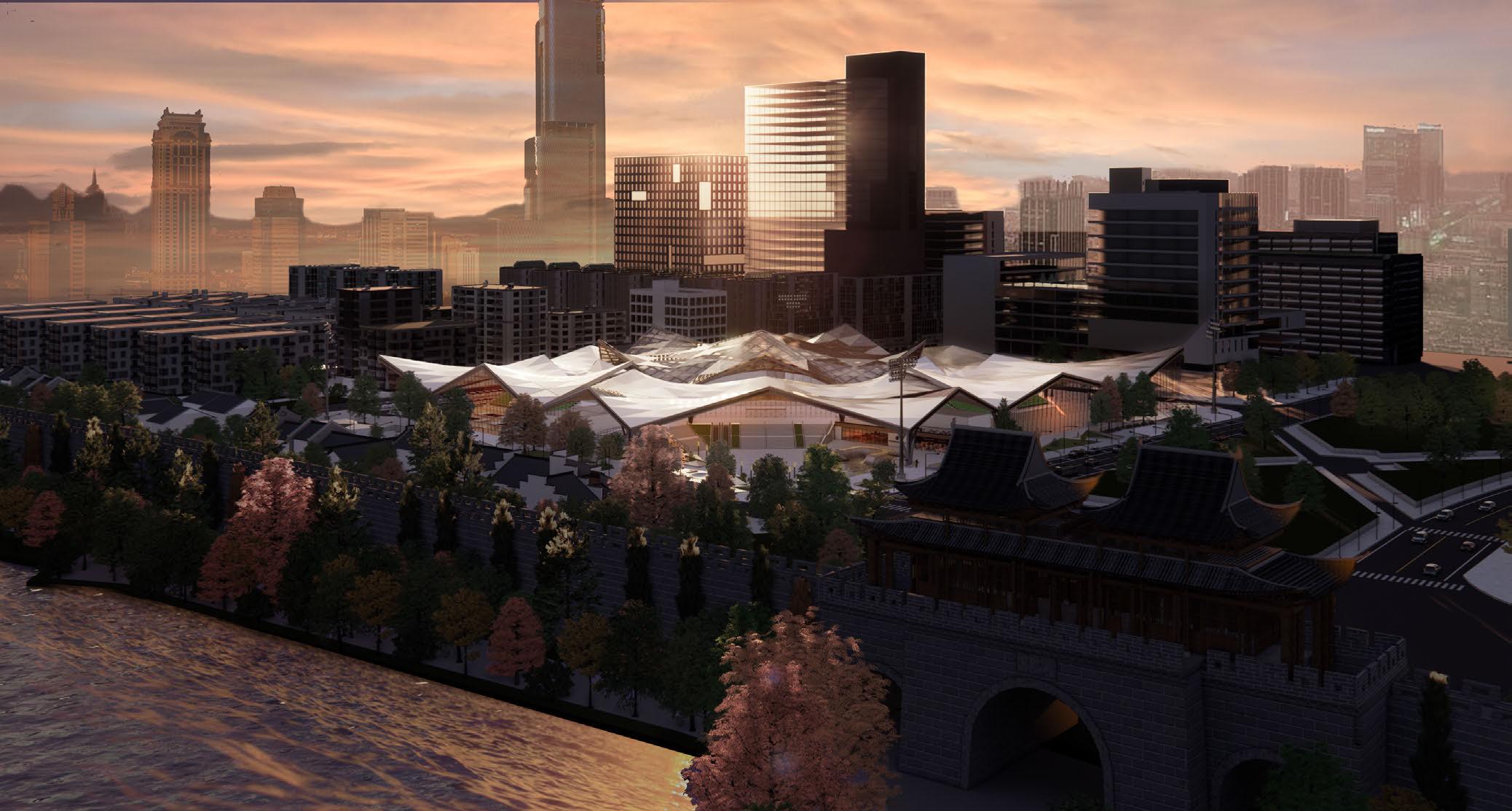
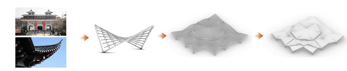
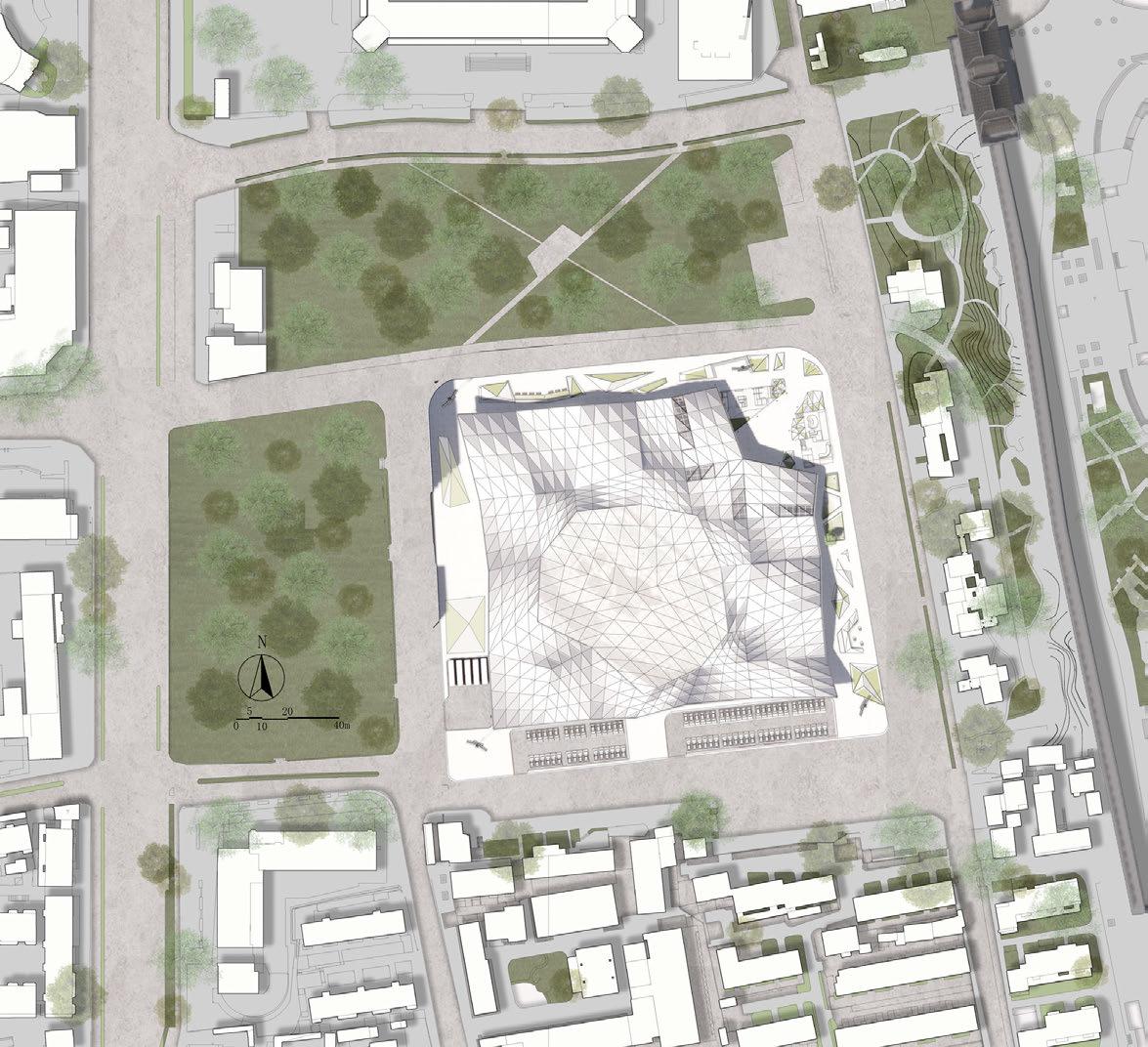
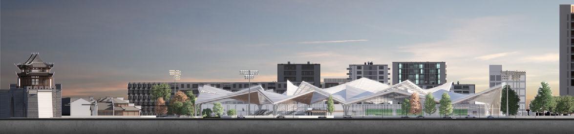
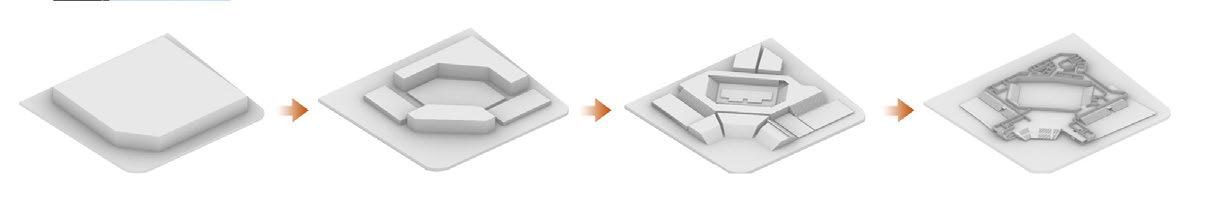
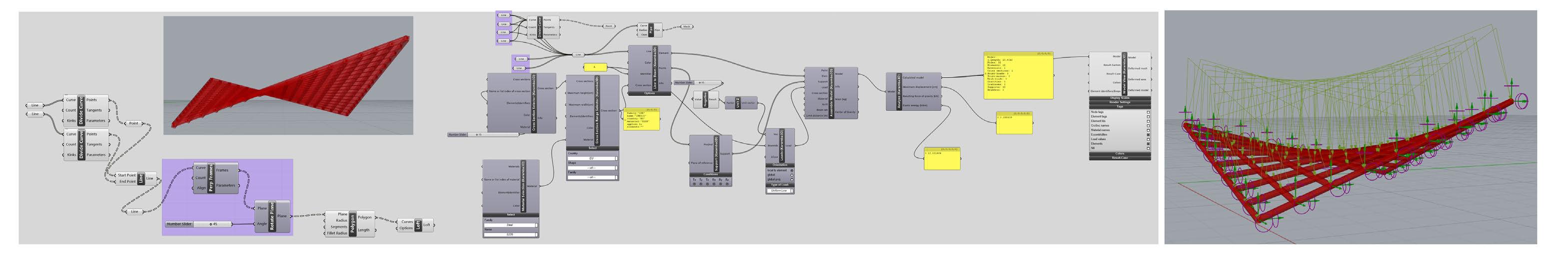
DESIGN OF LONG-SPAN
EXTREME SPORTS STADIUM
Type: Academic, Independent Work
Instructor: Xian Zhang
Date: 09/2021-11/2021

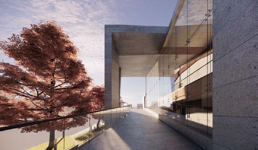
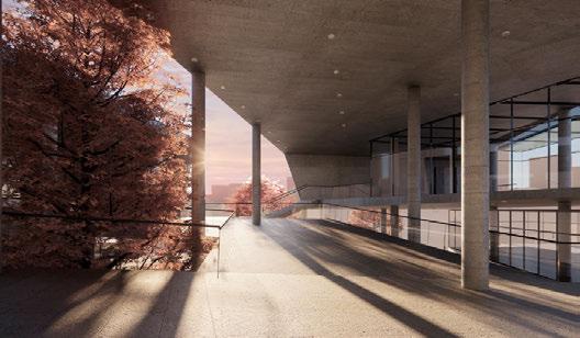
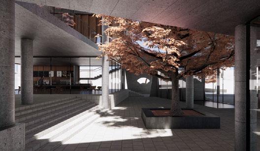
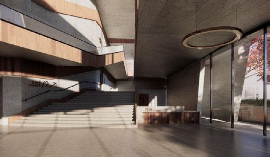
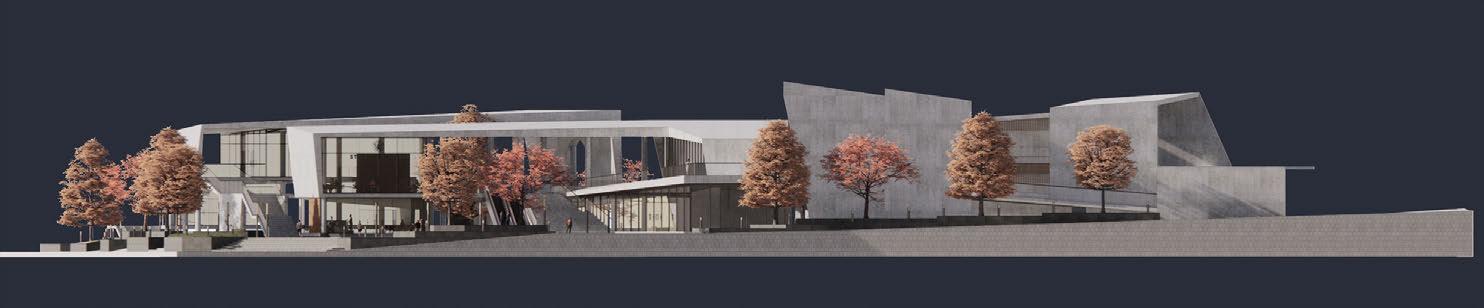
CONCERT HALL DESIGN
BASED ON TOPOGRAPHY
Type: Academic, Independent Work
Instructor: Xiaodong XU
Date: 04/2021-06/2021

ACOUSTIC
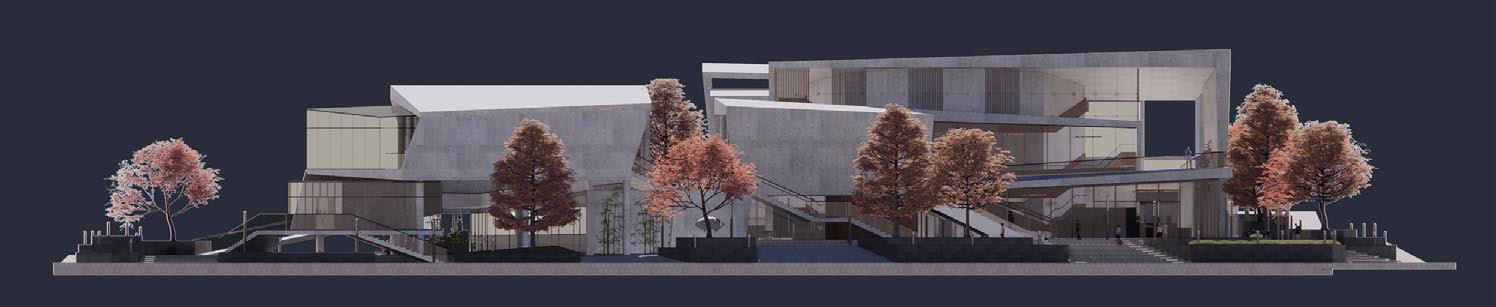


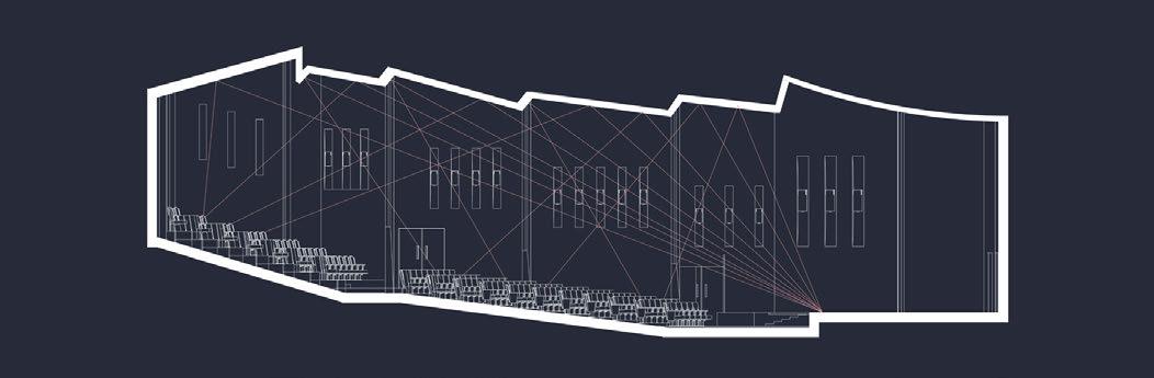
GENERATION PROCESS ELEVATION RENDERING SITE PLAN
MECHANICAL ANALYSIS OF STRUCTURE OTHER WORKS 2018-2023 OTHER
2018-2023
WORKS
ANALYSIS SECTION
ELEVATION
22 23
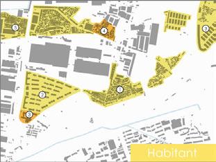
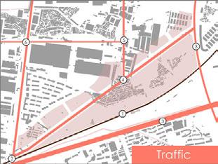
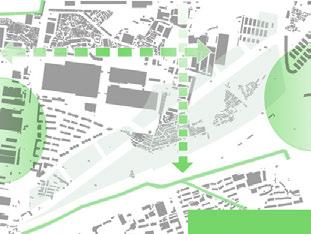
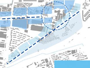
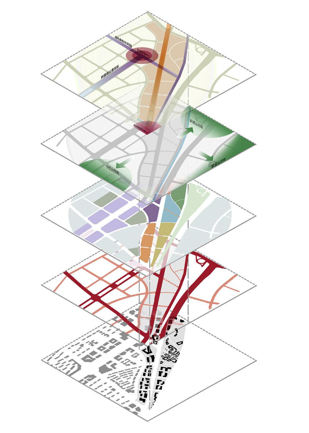
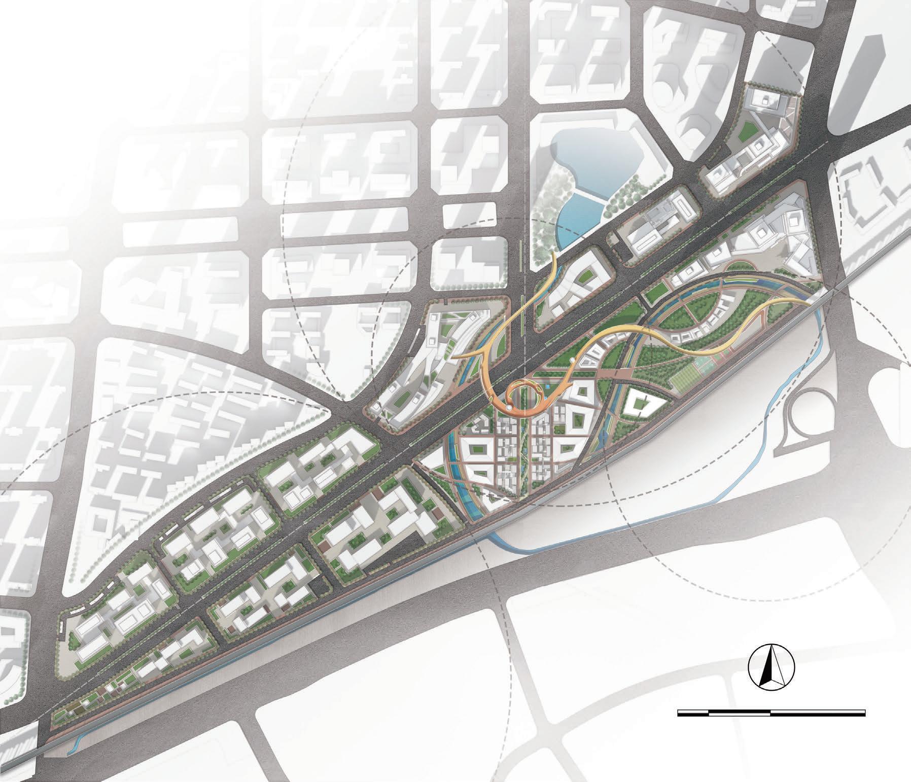
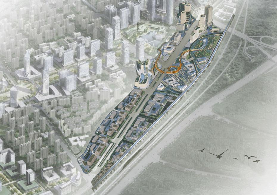
URBAN MUTUALISM - URBAN DESIGN OF THE SURROUNDING AREA OF CAOHOU VILLAGE, NANJING
Type: Academic, Collaboraive work
Instructor: Jie Liu
Date: 11/2021-12/2021


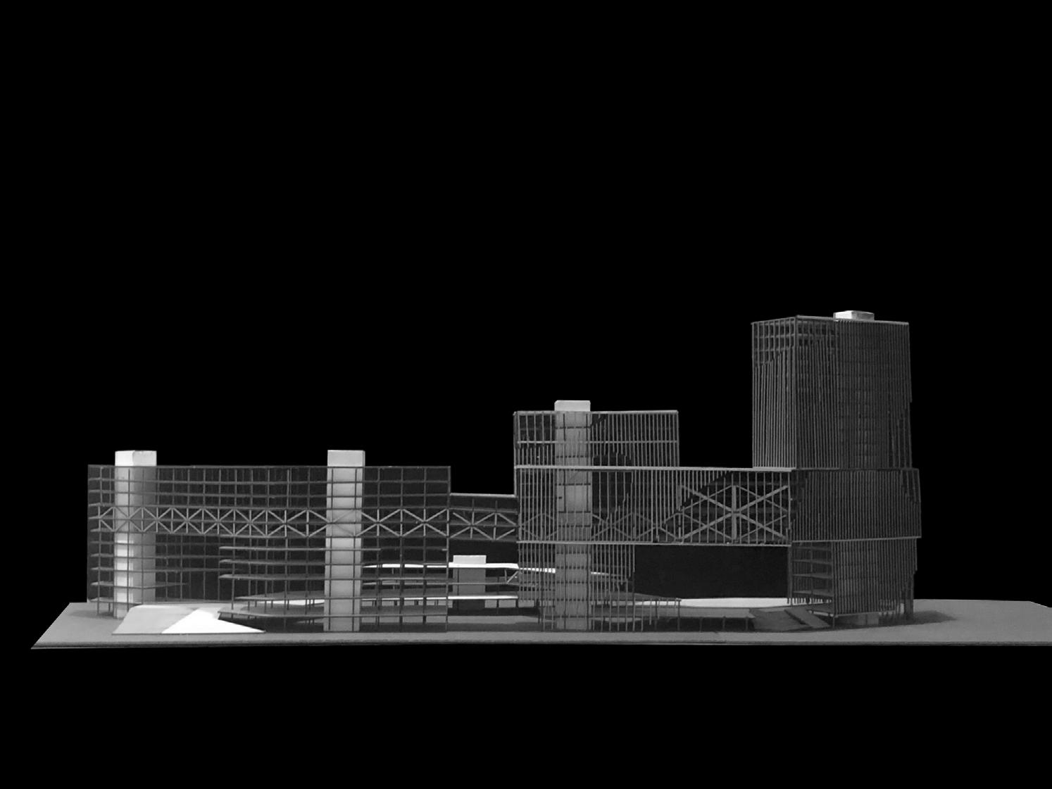
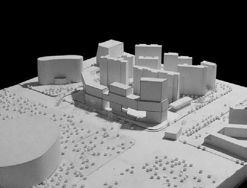
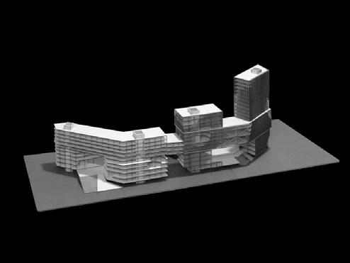
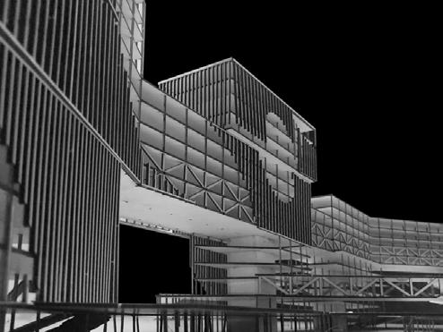
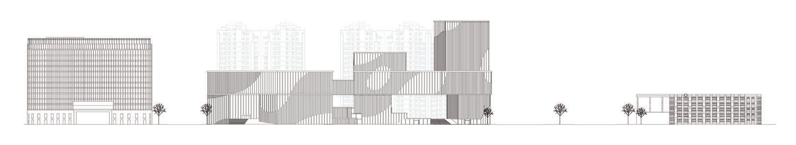
CITY COMPLEX DESIGN
Type:Academic Work, Independent Work.
Instructor:Xusheng Huang, Dietmar Eberle
Date: 11/2019- 01/2020
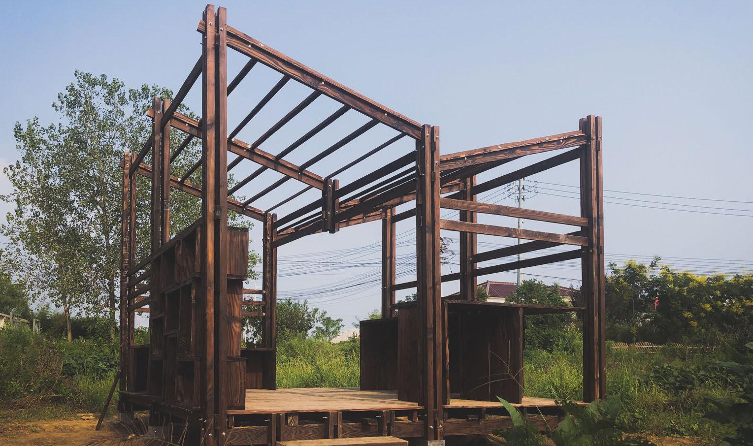
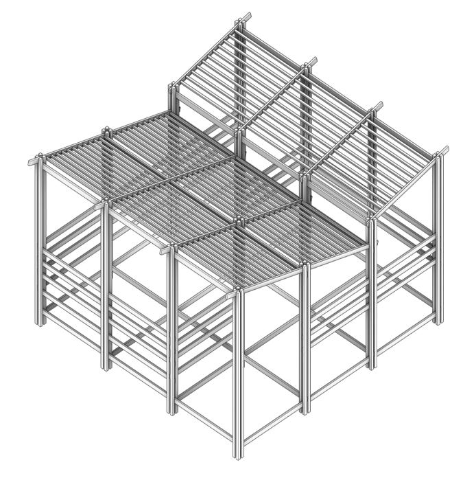
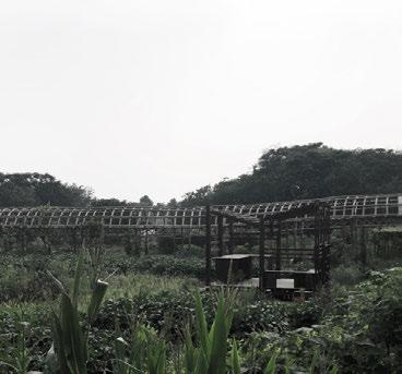
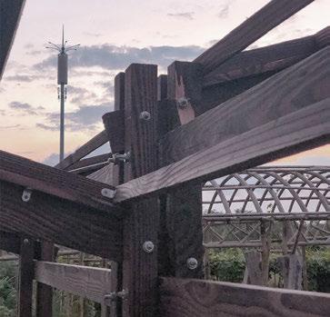
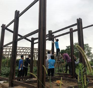
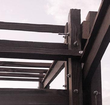
VILLAGE PAVILION
On-Site Construction in Nanjing
Type: Construction Work, Collaboration Work.
Contribution: Concept Design, Detail Design, Construction
Instructor:Wei Wang
Date: 09/2019
OTHER WORKS 2018-2023
SYSTEM ANALYSIS SITE ANALYSIS SITE PLAN BIRDEYE VIEW RENDERING 24
25
CELLULAR AUTOMATA FASHION PRODUCT DESIGN
Type:Academic Work, Collaborative Work.
Instructor:Jingyang Liu
Date: 02/2024

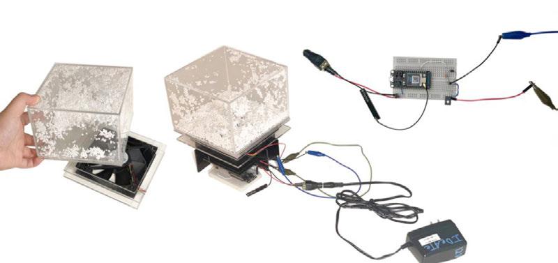
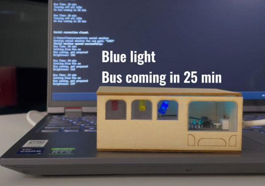
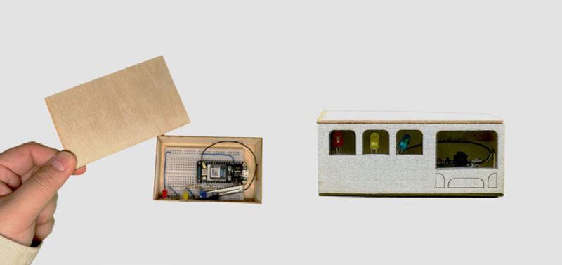
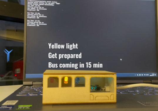
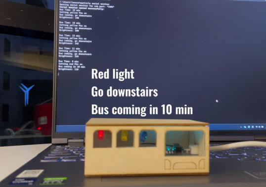
ARDUINO DEVICE FOR TRACKING COMMUTE
Type:Academic Work, Collaborative Work.
Instructor:Daragh Byrne
Date: 11/2023- 12 2023

Junke Zhao
Carnegie Mellon University
MS Computational Design
junkez@andrew.cmu.edu
THANKS FOR ATTENTION

(412)390-9219
OTHER WORKS 2018-2023
Full Introduction: http://ideate.xsead.cmu.edu/gallery/projects/bus-tracker 26