University Projects 2024
Luna Wang


I am a third-year student undertaking Bachelor of Design; majoring in architecture, diploma in music at The University of Melbourne.
This portfolio showcases a selection of my high-achieving design and documentation projects completed throughout 2024, titled:
• Design Studio: Beta
• Design Studio: Gamma
• Architectural Technologies
Over the past two years, I have developed a deep appreciation for the interplay between architecture, landscape, and urban contexts, which drives me to create harmonious spaces that acknowledge both modern lifestyles and the natural environment.
My academic journey has equipped me with a solid foundation in site analysis, spatial planning, and structural modeling, as well as a deeper understanding of real-world construction sequences and systems. This portfolio includes my recent designs, from concept sketches and site plans to detailed renderings and model prototypes. Each studio project represents my approach to design as both an art form and an amplification of functionality, addressing environmental and social needs.
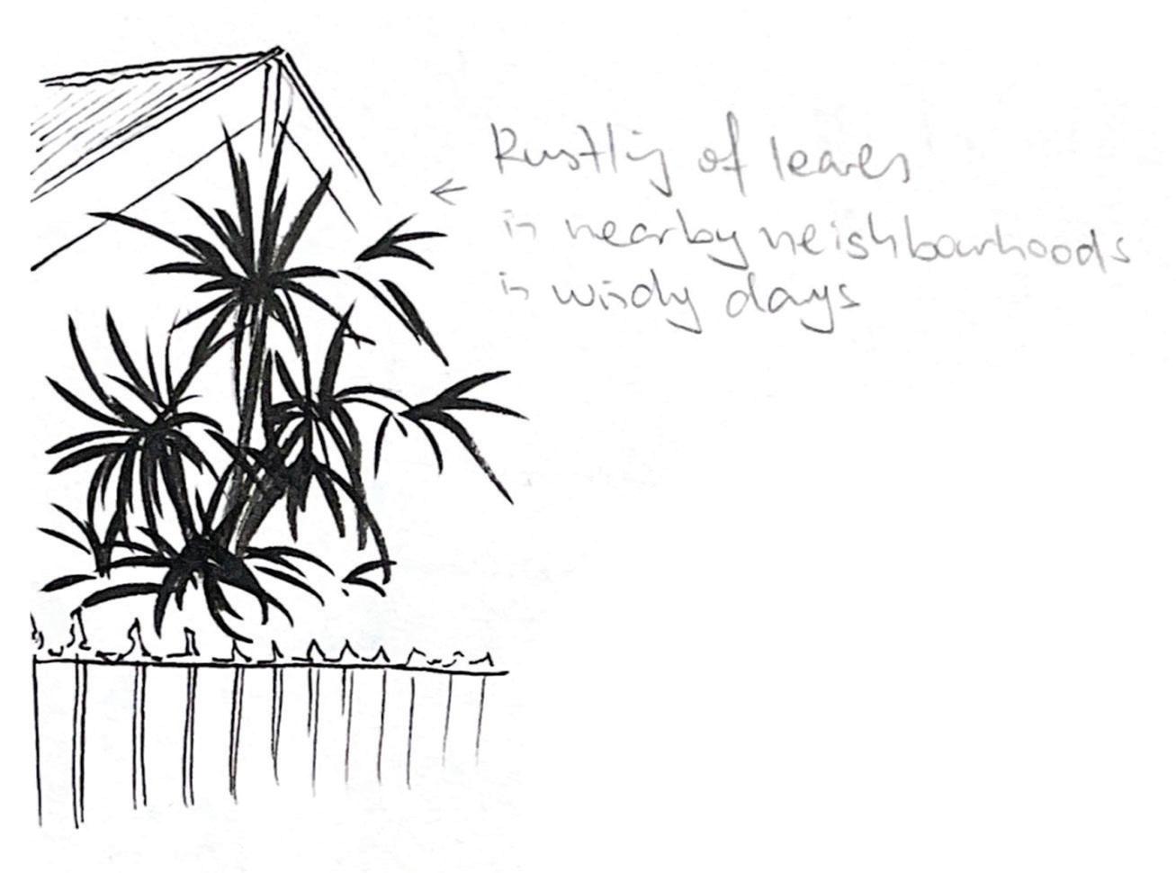
Studio Beta requires students to integrate architectural and landscape design, emphasising their interdependence in creating cohesive environments, through considering sunlight, shade, water, wind, heat, etc. The goal is to design an immersive public spaces that support contemporary social life, where gardens serve as spaces for gathering and interaction.
Site: Elwood community house reserve, 85-87 Tennyson Street
Non-Modifiable Elements
• Existing neighborhood
• Learning center and community hub
• Existing trees
• Existing access points
• Large rainwater tanks
Elements for Relocation or Redesign
• Community Garden
• Playground
New Pavilion Requirement
• Community kitchen and dining area
• Community event space
• Community reading room
• Accessible Unisex toilet with 2 separate cubicles and 2 washbasins.
• 2 x additional large rainwater tanks
New Garden Requirement
• Smaller, immersive and shaded garden spaces for quiet activities
• A sensory garden that registers seasonal change
• Open garden spaces that allow for outdoor community gatherings
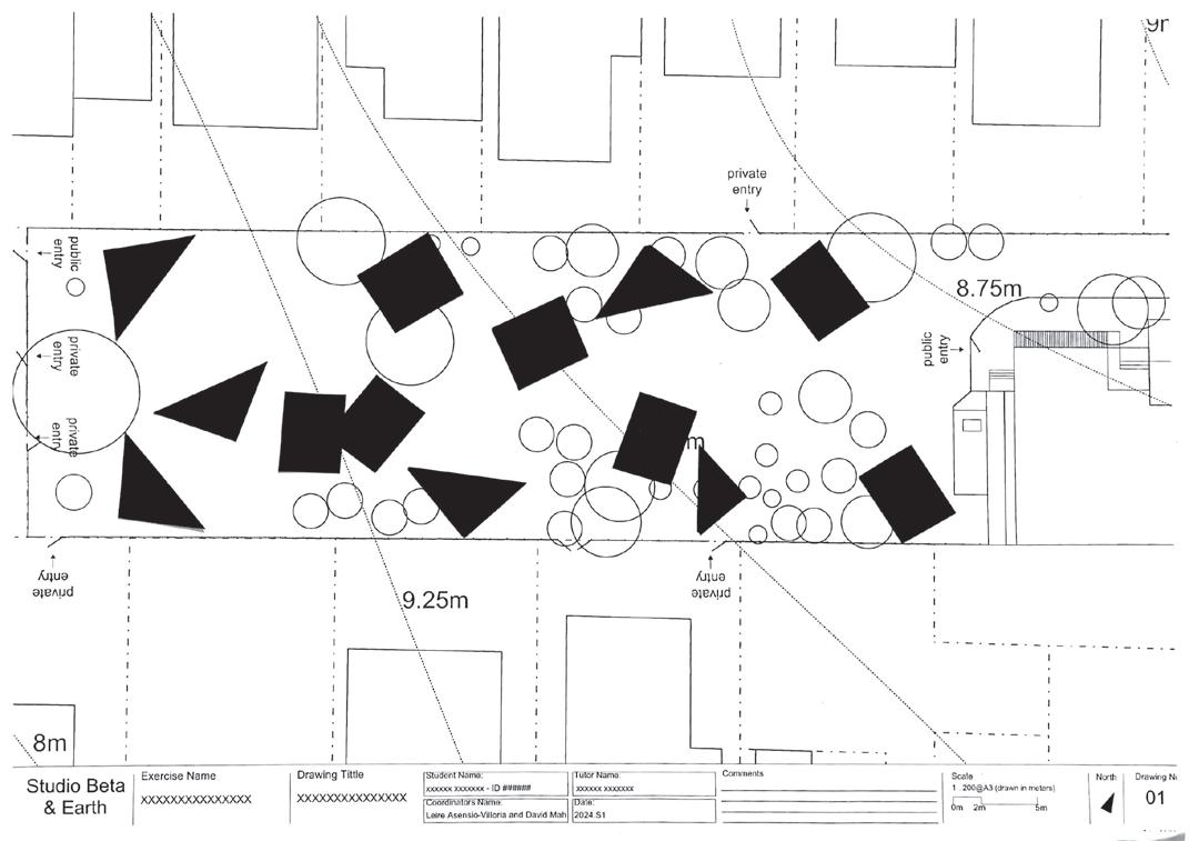
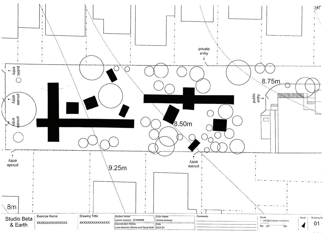
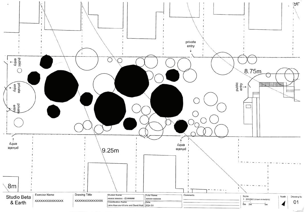
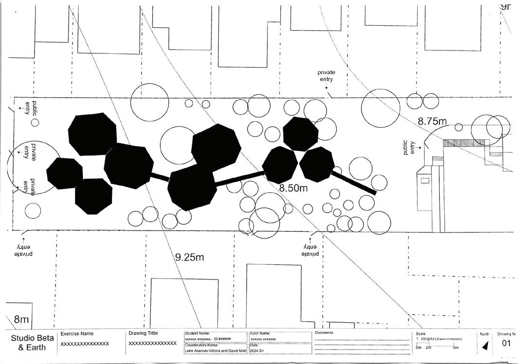
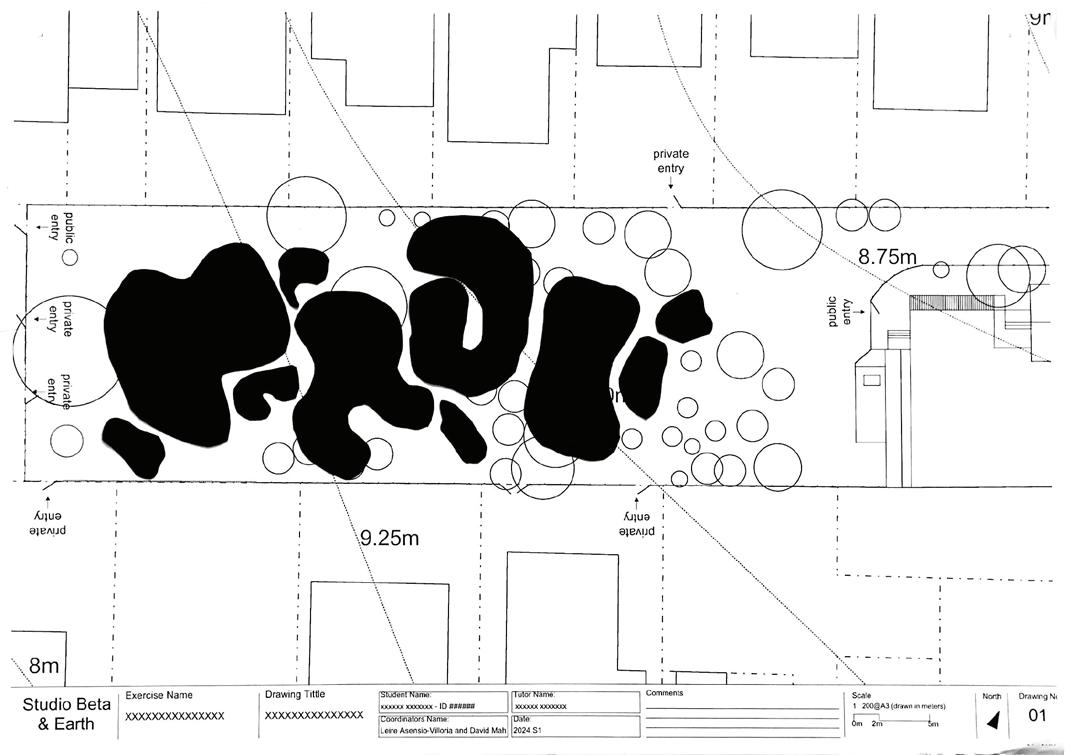
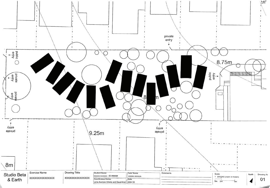
After comparing all iterations and evaluating their strengths and weaknesses, I chose hexagons as my primary geometric shape. Hexagons are highly adaptable, allowing for tight, flexible organisation and seamless connections. This shape also symbolises a close relationship with nature, as seen in natural structures like beehives, graphite, and other intricate formations. Consequently, hexagons effectively represent the integration of infrastructure and nature in my design concept. Additionally, as a polygon, the hexagon is more distinctive than circles within the context of a pleasure garden site.
Since nature remains the primary focus of the site, I wanted garden spaces to be dispersed rather than clustered in one area. Therefore, I arranged the programs to avoid distinct area divisions, creating a more seamless integration throughout the site.


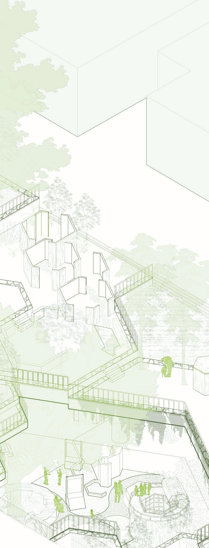
In Studio Gamma, students are tasked with designing urban greening solutions for Melbourne’s dense inner city, focusing on creating ecologically viable strategies that benefit both humans and wildlife. The project emphasises designing unique indoor-outdoor spaces, using greening strategies that support wildlife behaviors, and incorporating co-benefits like passive design, all while remaining adaptable to varying population densities.
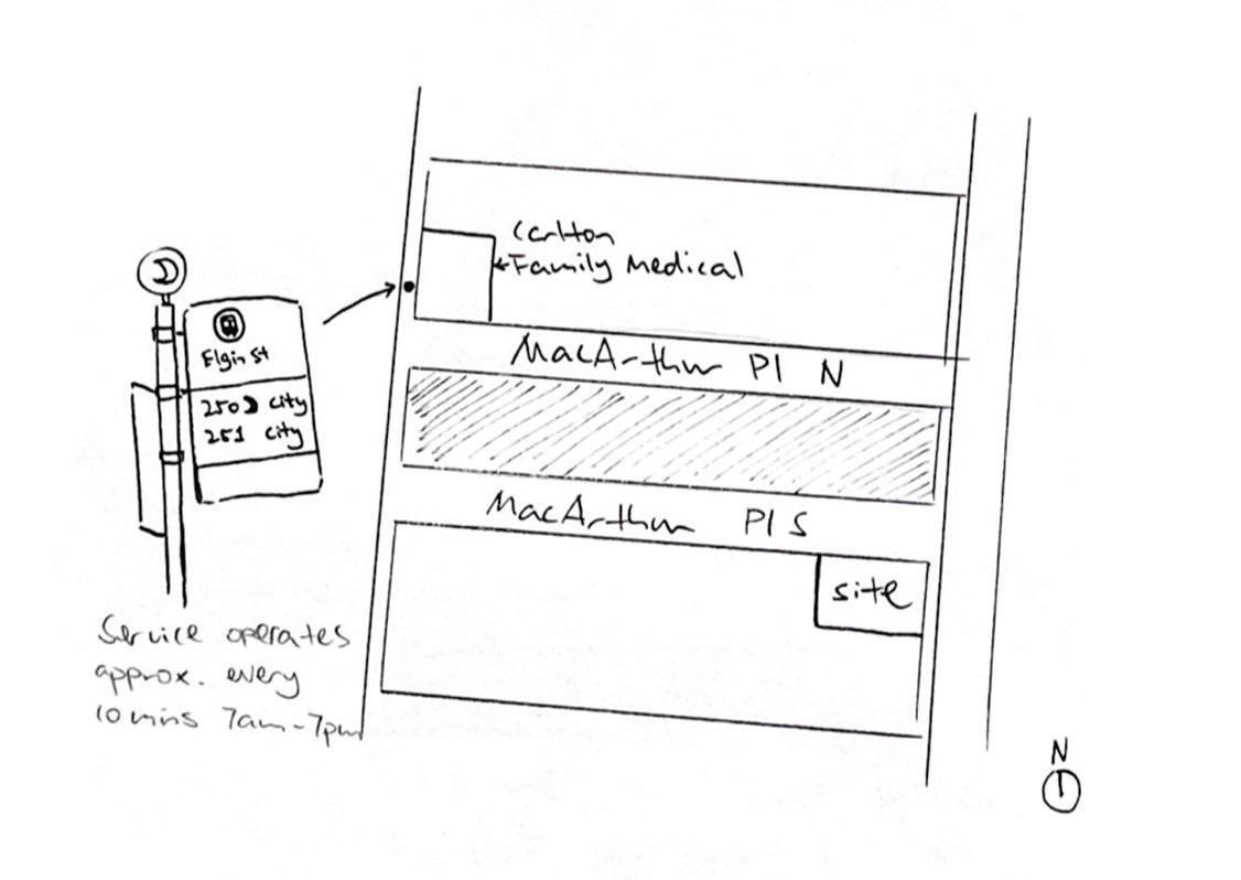
Site: 11 MacArthur Place South, Carlton
• Accommodate a minimum of at least 16 inhabitants across a minimum of 6 dwellings.
• Develop a diversity of at least 3 different apartment-types for single, two and multiple occupants.
• Create for all rooms which are for inhabitation (i.e bedrooms or living rooms), that have natural light for a minimum of 2 hours direct light on autumnal and vernal equinox.
• All dwellings must have cross ventilation to allow for healthy airflow and natural cooling during the night.
• All dwellings must have direct access to an outdoor space, e.g. balcony, terrace, ground floor garden or roof terrace.
• Leave a minimum of 30% of the site unsealed and exposed to weathering (open to the sky above it).
• Design with a minimum building height of 3 levels but do not overshadow neighbouring windows or outdoor spaces on autumnal and vernal equinox.
• Create for all rooms which are for inhabitation (i.e bedrooms or living rooms), that have natural light for a minimum of 2 hours direct light on autumnal and vernal equinox.
• All dwellings must have cross ventilation to allow for healthy airflow and natural cooling during the night.
• Include the following minimum shared facilities for communal washing and drying facilities, bicycle repair and storage, and rubbish and recycling bins. Additional shared communal space is desirable
• No car parking required, but include secure space for a minimum of 24 bicycles.
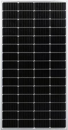
• All dwellings need to take advantage of passive solar gains; also include solar panels to generate electricity.
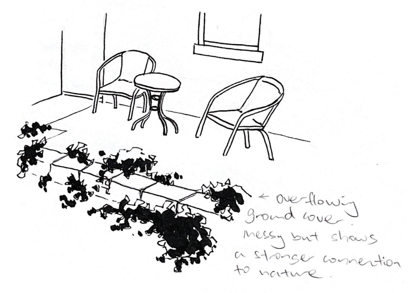
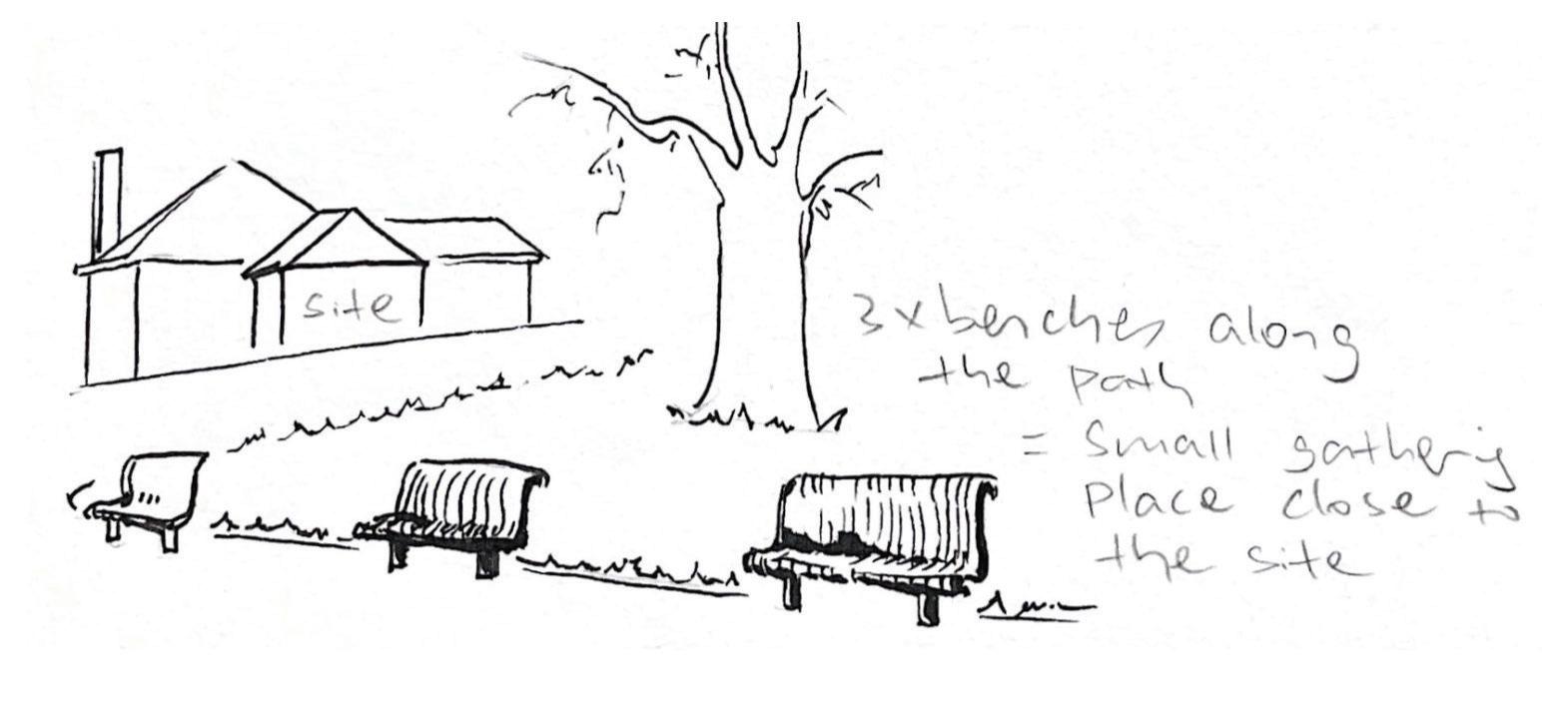
Overall, the neighborhood features abundant greenery subtly integrated into each house—whether intentional or not. This highlights a natural theme throughout the area, which will inspire my design to build upon these features.
Commonly pitch roof or block form as surrounding motif
Elevate the southern end ... ... for better solar intake
Concealed opening that enlarges internally to create privacy
Compress and extrude the south-east corner so that the western building can have better view
Trim and flatten the northern side to allow for a roof-top garden space
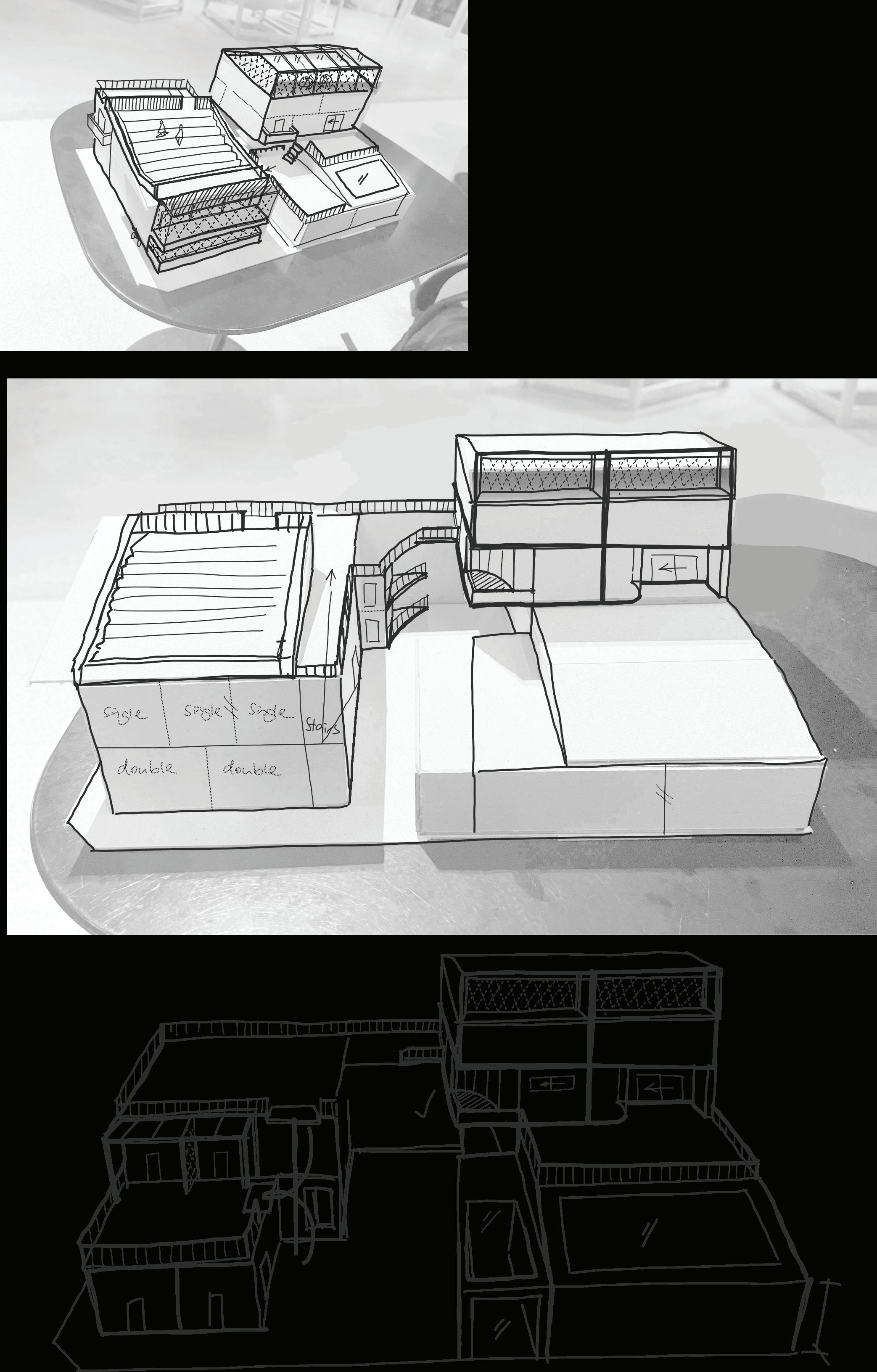
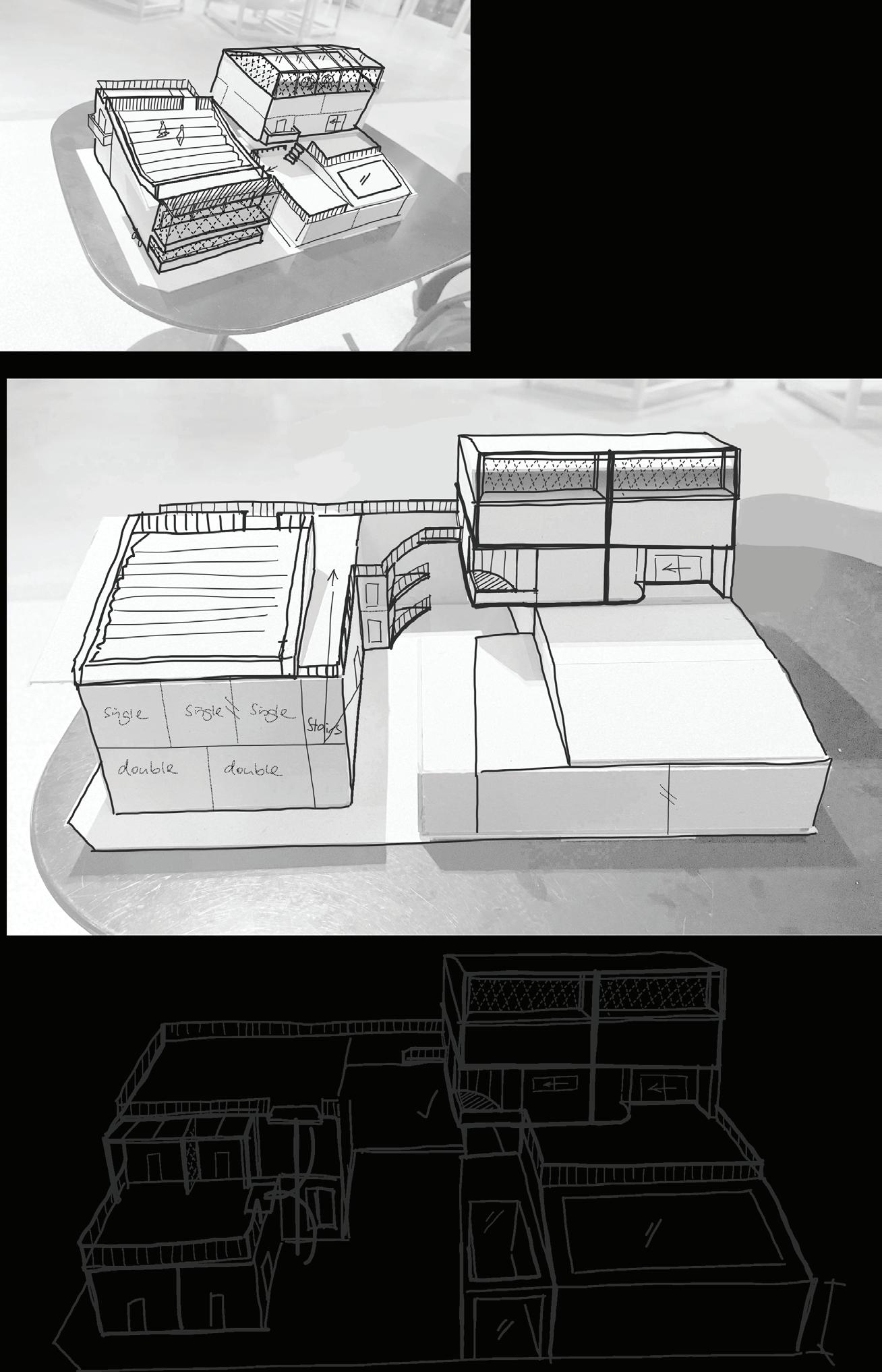
Iteration 2
• More private gardens by reducing one of the communal rooftop spaces
• Tighter incorporation of natural elements, such as hanging vines and display tree
• External spiral staircase to save space while enhancing vertical circulation
Iteration 3
• Removal of the spiral stairs due to inconvenience and tripping hazards
• Removal of Ground floor skylight due to unnecessity, for a larger communal garden above
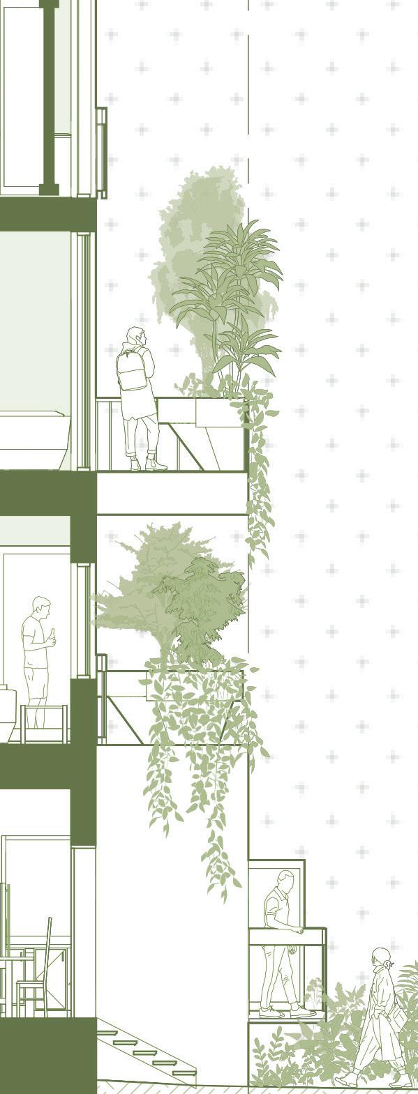
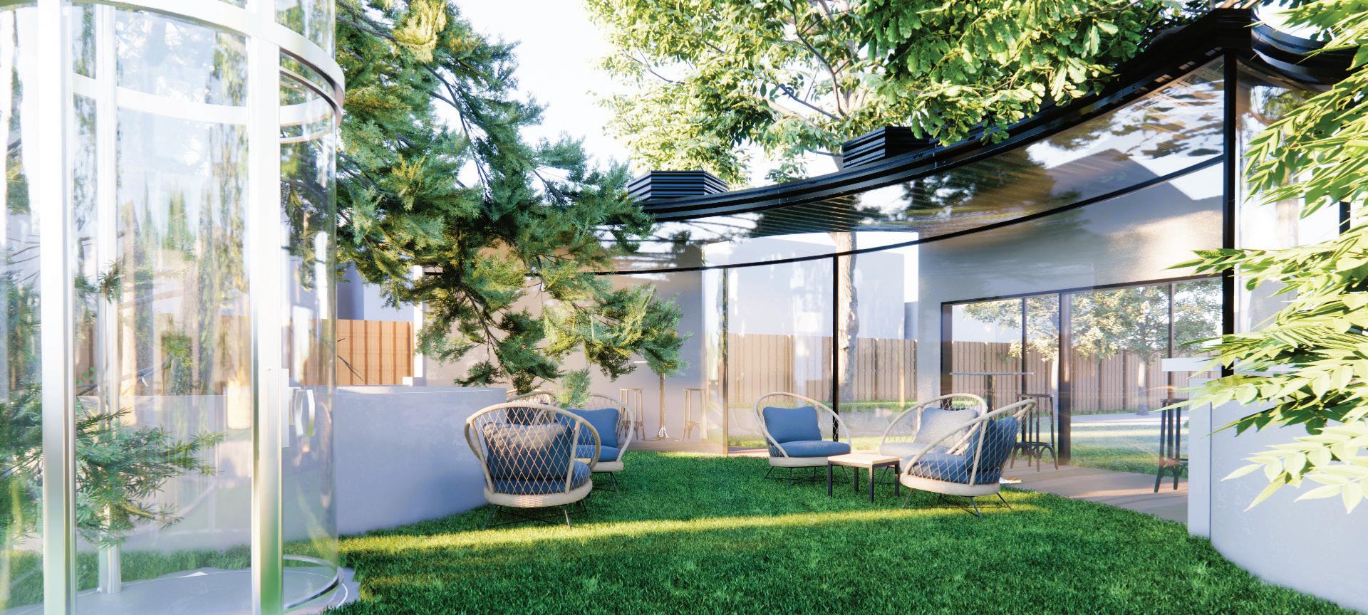
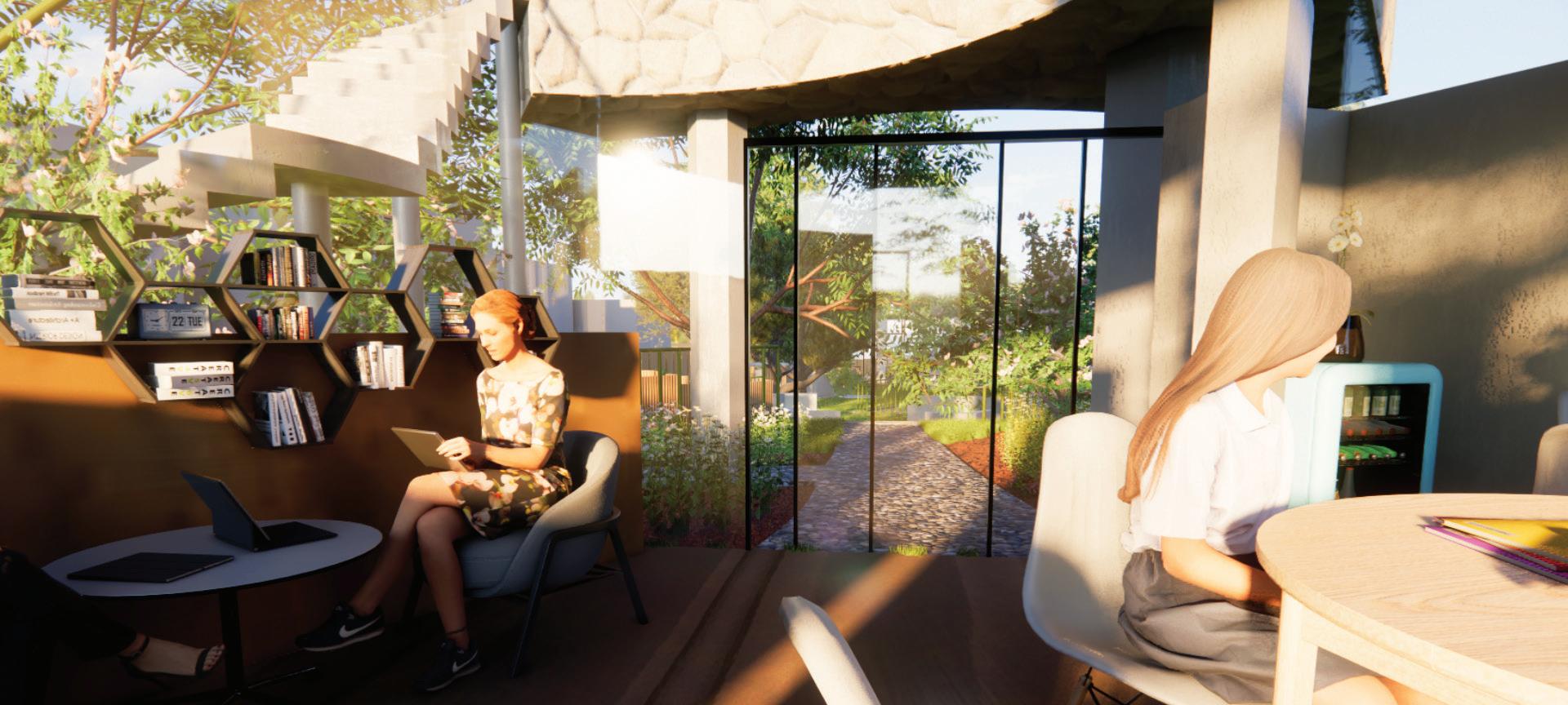
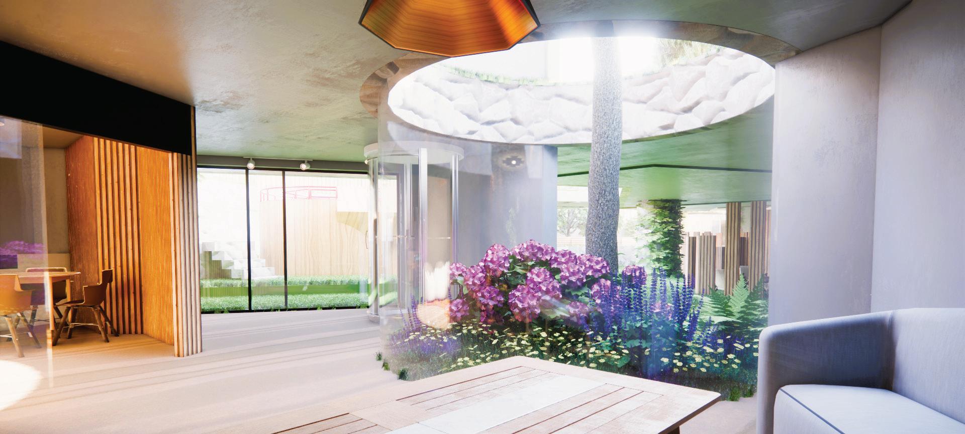
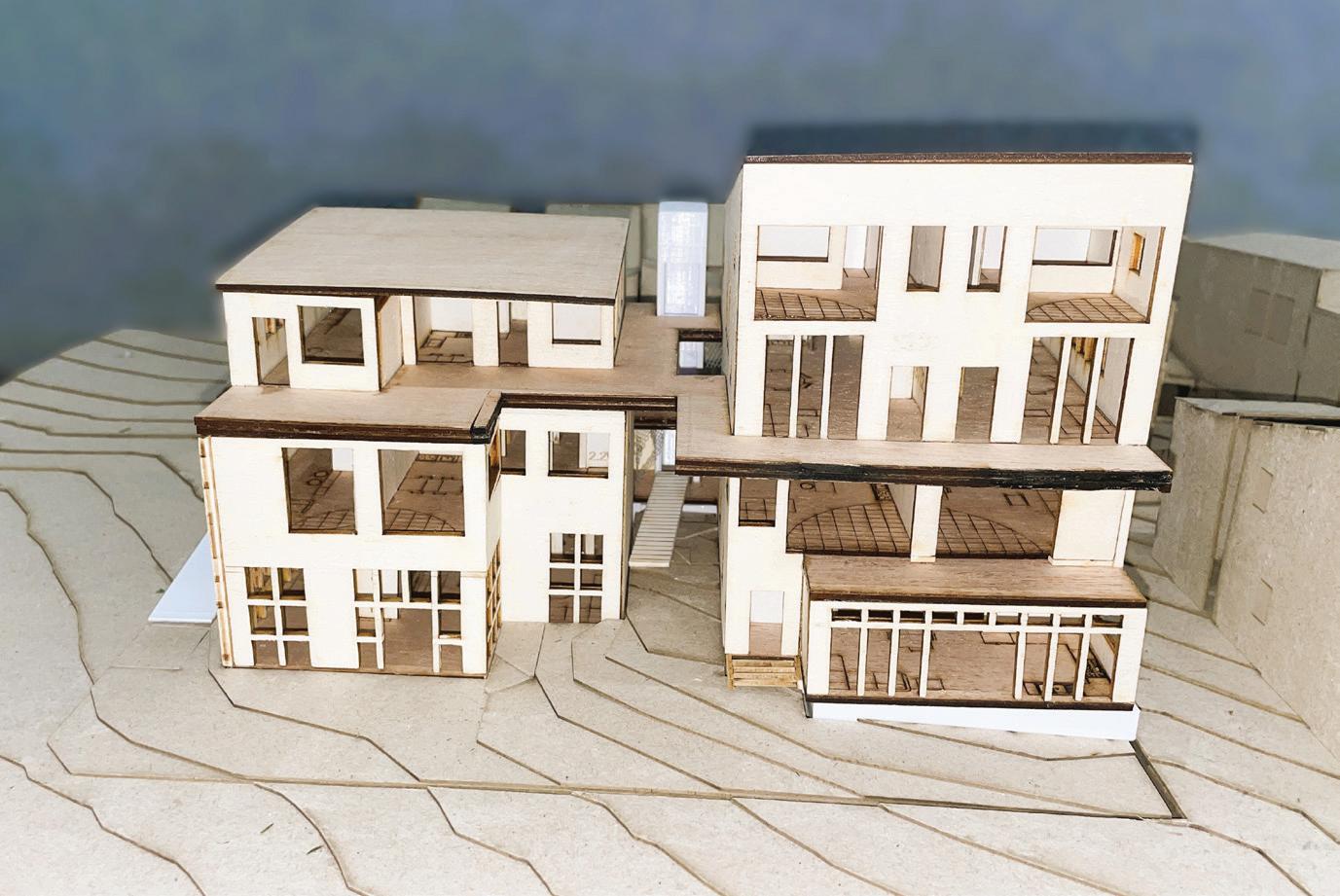
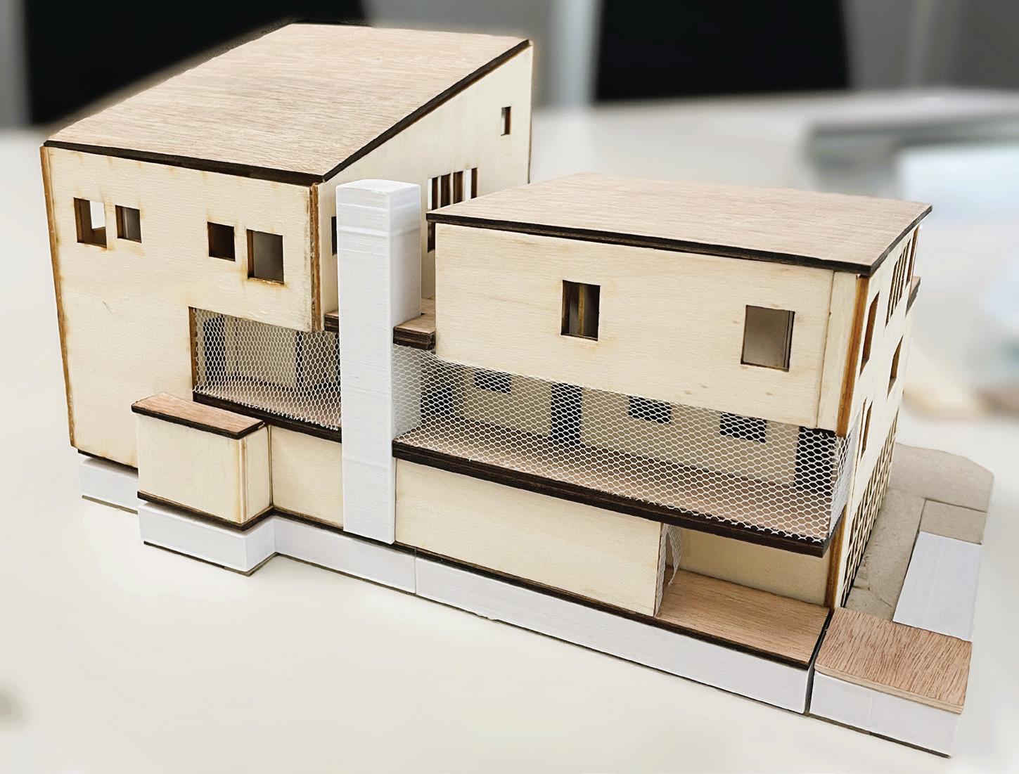
In this stage, I focused on exploring sheltered living that better suits a modern lifestyle. Inspired by precedents, natural elements are integrated into the building itself through an indoor communal garden on Level 1, potted trees, and custom landscaping on each balcony. A curved motif creates seating opportunities or other affordances. These features seek a balance between indoor and outdoor experiences, allowing for an appreciation for nature while prioritising residential preferences.
Weakening the threashold between indoor and outdoor space
Intensivly incorporated landscape at ground level near the communal space
Potted trees on upper levels to expand residents’ access to nature
Site boundary
Embedded rather than hanging balcony to promote the connection with nature, while adapting to the common indoor lifestyle
Maximum building volume
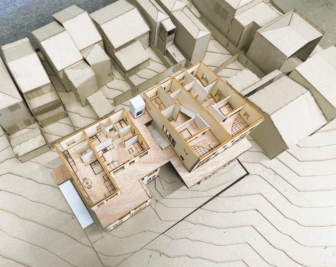
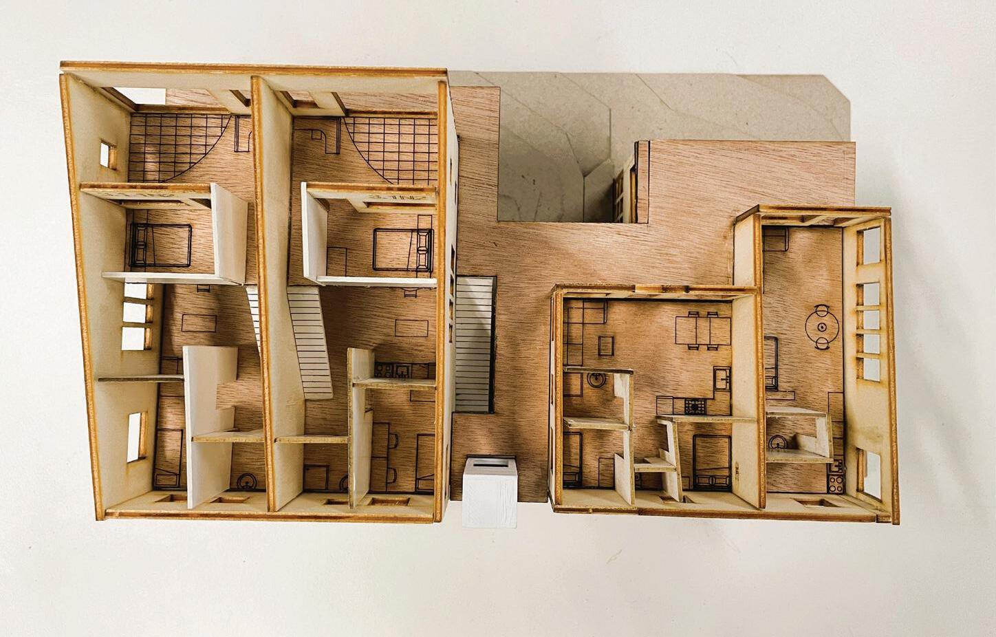
Adjusted level heights to create a flush finish with the topography regardless of the slope
Cutting through the mass to allow for one centuralised pathway, enabling larger dwelling size
Linear dwelling division to optimise North-South corss ventilation and sunlight/view
Level offset to increase sunlight intake as well as upper level pathway & ‘moments’
The massing is further divided to max. three levels, allowing for more housing diversity
Extruded edge to increase the surface count to rear areas, allowing better sun and wind access
Massing on the East is kept at two-stories tall, to avoid obscuring the views of the adjacent one
Relating to the common indoor lifestyle in modern society, my design focuses on sheltered living, investigating “how much indoor space is enough while exploring ways to incorporate natural element to enhance such style. Starting with the spatial planning, each dwelling is relatively larger sized, with approximately minimum 35 square meters for a single person studio, and can range to 100 square meters for a family unit, thus challenging the progressively decreasing size for inner Melbourne apartments.
On top of the liner shaped dwelling that maximises sunlight and north-south cross ventilation, access to greenery is provided for all levels through potted short trees and herbs, extending the garden vertically. By concealing the platform to dwellings, not only greenery enhances privacy, but also transforms mere circulation to a gazebo, allowing for small moments of interaction or appreciation. Planter boxes are used similarly to separate areas, defining the private and shared spaces, creating two entrance balconies without achieving so harshly via fences. Balconies are designed with different flooring material to define the space, yet are embedded within the unit. This space is therefore practical but also transformable, allowing for flexibility in use that is determined by the actual residents. This incorporation dissolves the harsh boundary between indoor and outdoor, highlighting the harmony between sheltered and natural space that provides a comfortable living experience.
Altogether, the concept of a ‘blurred threshold’ is solidified.


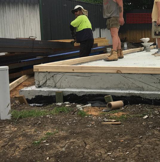
In analysing one part of the Northcote House by Star Architecture through its architectural, engineering drawings, and other associated documents, the primary building process is conveyed through both 2D and 3D drawings, offering insight into the construction logic—including the order of assembly, rationale behind material choices, and the coordination and communication throughout the project.
While PartA of this study primarily focuses on the building sequence, the subsequent section delves deeper into evaluating building performance and design intent.
Description (see Plan for more details on terms in bold)
Soil Test
• Produced to provide insight on the site’s soil quality.
• It also recommendations the footing depth depending on the bearing needs. The engineer decided for the footing to have a 250 kPa, which linking to the report, needs to be founded with “600 mm penetration into the silty clay”. [Soil Test, p.3] The silty clay has a total depth of 700mm, from 200-700mm depth into the ground. [Soil Test, p.8]
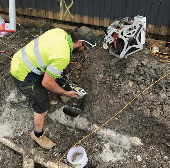
• Water, gas, electricity, Telstra, sewer, etc. are checked on site prior to commencing any work. [C01-A]
•
• Remove the existing house and their footings with a excavator.
• Site set out by Surveyor using String Lines across the site and markers on the soil.
• All trenches and holes are filled with natural clay that are compacted at an appropriate moisture level as per AS2870-2011 6.4.2(b). [S2A]
• Slab boundaries are outlined to later inform the excavator.
• A small sized boring machine is used to reach the base horizon of the clay level, which is approximately 1.5m deep **Ground level reduces during excavation, and restored by the end of Stage 1.
• Pipes are reorganised or added. Stormwater drain and sewerage are separated, referring to the
• The root of concealed down pipes are also arranged at this stage, pipes have 100mm in diameter. The excavated area above the pipes is backfilled with 3% Cement Stablized Sand. 6.1.1
• Pipes are wrapped with lagging to prevent cracking. 6.2
• Exposed opening are also covered with duck tape to prevent concrete from splashing into the pipes.
Concrete
• Temporary formworks are likely used for certain areas before the pour. 7.1
• 15MPa (low strength) blinding concrete is poured, 800mm deep, to ensure the footing is placed at the right depth, also to provide stability in case the soil is relatively soft.
Concrete Slab
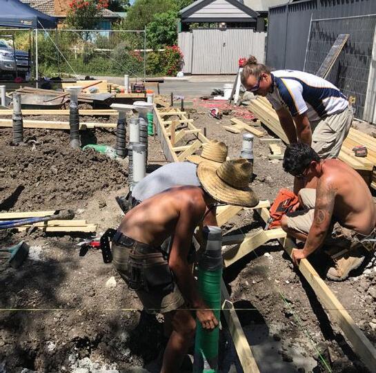
• Concrete Formwork placed with a laser level on site, using timber and plywood, in order to hold the shape of the concrete as it is being poured. The formwork will also mould the concreate to create a rebate that has a minimum depth of 230mm. The rebate is used to protect the house from water by elevating it.
**Rebate formwork in section: is for diagrammatic purpose only, to showcase its relevance to an Edge Beam. It is not used in reality due to the Edge Beam is directly next to the title boundary. For more accurate placement of formwork, please refer to the plan instead.
• The excavator is used again to scrap out some paths for Edge Beams to be fitted later.
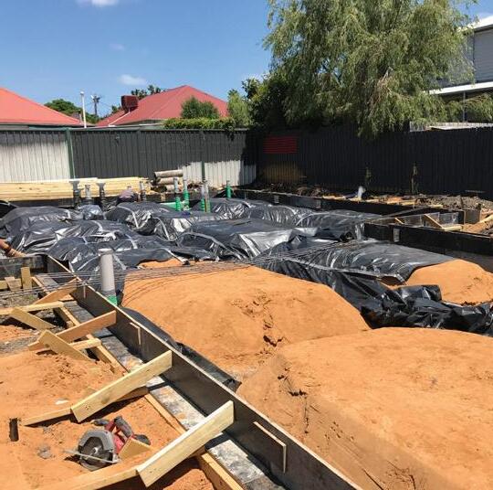
• Approximately 200mm of Engineer Fill is piled as multiple small rectangular dunes, each with 25mm compressed Sandbeds on top. They function similarly to the timber formworks, but mould the footings from underneath. They will also be directly under the slab to provide extra support. 8.3
• Waterproofing Membrane is placed over the sand beds.
• While it's not clearly stated, termite
instead. It is also likely that the project uses chemical termite treatment, that happens possibly at Stage 6.
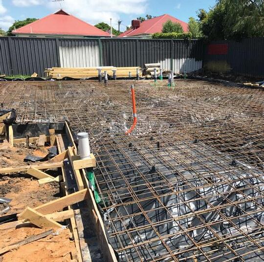
Reinforcement (ordered from bottom to top)
• 3-L12TM Trench Mesh with three rebars.
•
• 2-N12: two Rebars.
• SL92 Square Mesh, same as before.
• Bar Chairs are placed between meshes to vertically separate them, so that they are more effective at reinforcing.
•
the foundation. 10.1.1
• The Concrete Slab is 130mm thick, with 25MPa (standard strength).
• During the pour, an Immersion Vibrator is used to eliminate air bubbles.
• Worker uses shovel to spread the concrete.
• Worker uses screed to level the concrete.
• The slab surface can be further smoothed with a Trowelling Machine.
• The concrete will be dry enough to walk on in 24-48 hours; however, it requires 28days per inch of slab thickness to reach its full strength, which will be about five months in this case. 11.1
• Formwork can be removed after 3-4 days. 11.2
• Water is sprayed on to the slab continuously during its curing phase, about 5-10 time per day for the first seven days. This prevents the concrete from cracking in hot weather and ensures that both the top and bottom layers cure evenly by stopping the surface from drying faster than the bottom.
•
Name Code Description (units in mm) Building Performance & Design Intent
Trench Mesh 3-L12TM Low ductility. Has 3 rebars, each is 12 in diameter; connected cross wires. It sits 50 above the base of the footing.
Square Slab Mesh SL92 9 in diameter, 200 spacing. One sits 20 below the surface, the other sits 30 above the base of the slab.
Rebar 2-N12 2 rebars with normal ductility. Each is 12 in diameter. Sits 25 below the slab surface. It is tied to the underside of the upper Slab Mesh.
Edge Beam EB1 300wide x 600deep. Standard strength (25MPa) concrete beam. Works together with 3-L12TM and/or 2N12.
Internal Stiffening Beam SB1 300wide x 600deep.Standard strength (25MPa) concrete beam. Works together with 3-L12TM and 2N12.
Internal Pad Footing PF1 600x600x600. Standard strength (25MPa) concrete footing.
**Contradiction between Structural diagram and annotation. Reinforcement for this footing type could be either 3-L12TrenchMesh or SquareMesh81. [S3AS4A] ***3-L12TrenchMesh is drawn in my section for diagramtic purpose.
Used to reinforce the concrete footings.
N/A
Used to reinforce the concrete slab. N/A
Used to reinforce the slab near edges. N/A
Used for the edges of the slab. N/A
Used between Edge Beams to prevent deflection of the slab.
N/A
Used for shallow foundations to carry concentrated load due to columns.
N/A
Waterproofing Membrane N/A 0.2 thick polyethylene films. It is placed over the Sandbeds to prevent moisture entering the Footing and Slab.
Hydronic Heating HHM Coiled pipes with Manifold. ‘Second Pour’ system provided by H2O Heating Each pipe is 37 in diameter, that are positioned on a 37 thick polystyrene based Insulation Sheet.
N/A
The Insulation Sheet is used to create thermal break between the slab and screed, forcing the heat go up into the house, achieving better result and is more time efficient.
The Heating Pipes work by warming up thermal mass rather than blowing hot air. Since this system is slow to heat and slow to cool, it is suitable for stabling temperatures long term with even heat distribution, resulting in a comfort environment; although this system is expensive.
Waterproofing
Description (see Plan for more details on terms in bold)
Structure (details in Plan)
•
•
• Larger
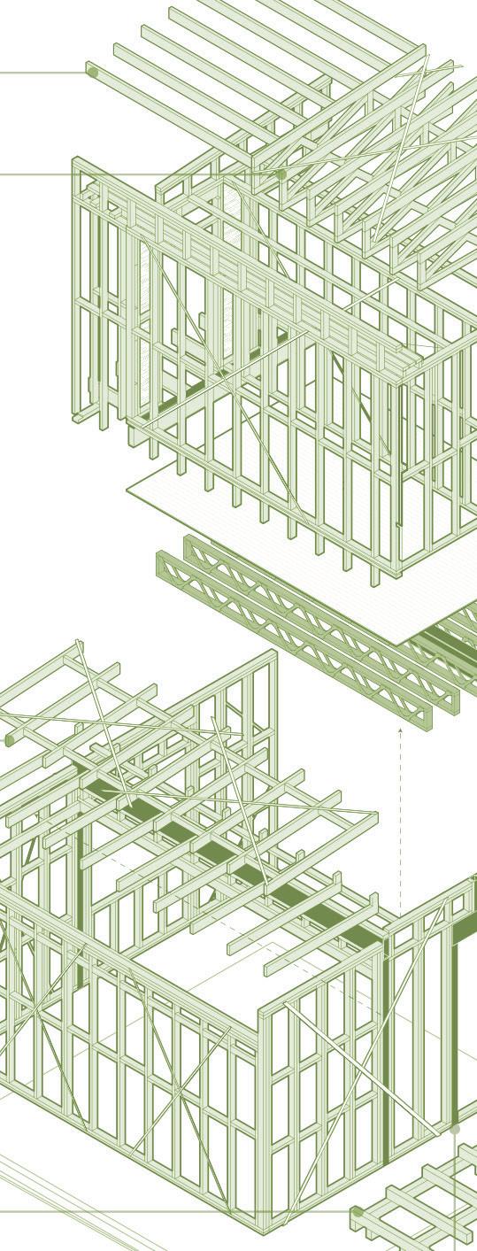
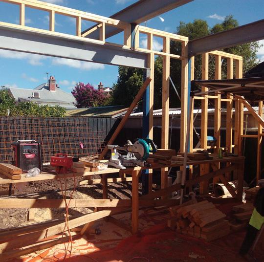
Hollow Sections, or perpendicularly to each other. These steel beams complement the existing timber structure, by providing great support to the upper level. They also allow the house to feature a large and open space on the ground level by not needing studs in between.
Roof and Upper Level Floor
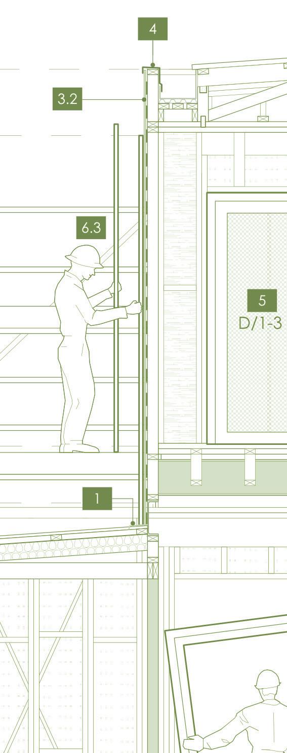
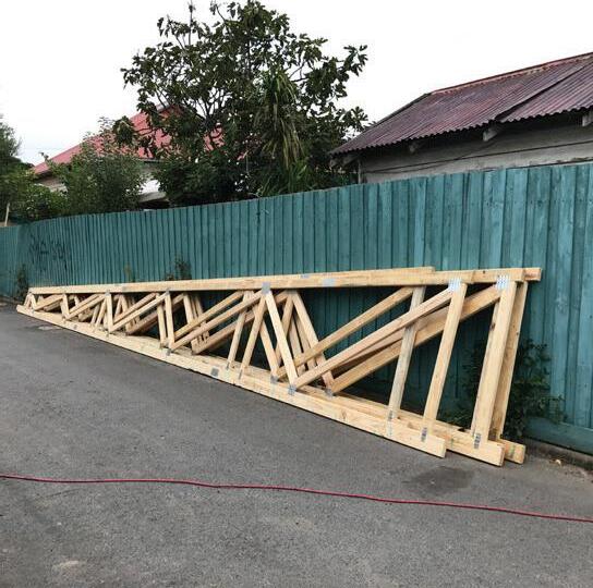
• Posi-Struts are installed between the ground and first floor. They have a top and bottom chord (flanges) of Laminated Veneer Lumber with solid webs in between. They are pre-made structures that supports the long span of the room, that are perpendicularly fixed to the packed timber piece inside of a Parallel Flange Channel. Despite being relatively more expensive than a Timber-strut, they are high quality, and more convenient for maintenance as there is more space around the steel web. [W4.1 Lecture]
4.2 • Kiln Dried Hardwood are used as joists for the upper floor balcony. 4.2.1 •
• Machine Grade Pine 10 Double Studs (90x45) are used at below the ends of all Lintels, Roof and Floor Beams. [S9B] 4.2.3 • Machine Grade Pine 10 (190x45) are used as upper floor Linterls.
4.3
• Structural Grade Particleboard Sheets are installed on top of the joists and Posi-struts as the basic flooring system.
• The
• Strap Bracings using Galvanized Metal Straps, looped over the top plate, fixed to studs and through joists. They are used to provide stability to the wall frames against lateral loads. They are used for wide wall spans.
6.2 • Ply Bracing nails plywood to the external side of the timber frame, for small walls.
6.3 • Hardboard Bracing functions similarly to Ply Brace, but for even narrower walls. 6.4 • Pryda Speed Brace is used on top of the ground level rafters. **Ground floor Bracing occurs simutaniously to upper level Structure.

Name Code Description (units in mm)
Building Performance & Design Intent
Square Hollow Section SHS: C1 89 x 89 base, 6 in thickness. They are used between studs, as additional load bearing element mostly for other steel structures above.
Machine Graded Pine 10
MGP10: GL3, FB. Strength Level 10. 2x 240high, 45deep.
the Posi-strut
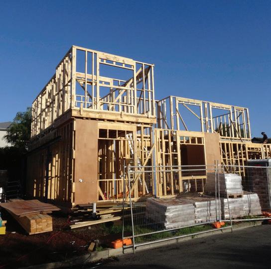
Showcasing the construction sequance: Ground floor Bracing occurs/ finishes during Upper floor Framing. Studs are used as temporary bracings.
N/A
This size of MGP10 are used in pairs for Lintels and Facia Beams on the Ground FLoor, to match the width of common studs (90). It is especially taller than other MGP10 used, to pass the upper floor load more effectively to the foundation. It could also due to the lower placement of the window {WG-8}.
N/A
Machine Graded Pine 10
Machine Graded Pine 10 Double Studs
Parallel Flange Channel
Parallel Flange Channel
Universial Beam
Posi-Strut using Laminated Veneer Lumber
MGP10: RL1; R1. 190high, 45deep; 140high, 45deep, 600centres.
The first size is as upper floor door Lintels; the second as rafters. These MGP10 are relativly shorter comparing to the previous one, but for taller window placements.
N/A
MGP10: DS. 90wide, 45deep. Common studs are replaced by MGP10 in the same dimension for better support. They are mostly used below Lintels, Roof, Floor Beams, and sides of window openings for better support.
300 PFC: GL1, B9, B10. 300high, 90wide, 16flange-thickness, 8web-thickness.
230 PFC: B5. 230high, 75wide, 12flange-thickness, 6web-thickness.
310 UB: B8. 298high, 149wide, 8flange-thickness, 5.5web-thickness.
PSJ Vary in sizes and timber grade; but likely to be 90x45 MGP10, 450centres to suit 1.5kPa live load on the upper floor.
Kiln Dried Hardwood
KDHW: J 190high, 45thick, F17 Grade.
This type of timber is processed in a kiln (oven), by controlling air, humidity, and temperature to reduce moisture without damage.
Structural Grade Particleboard Sheets
N/A ‘Yellow Tongue’ type: 19thick. It is an engineered wood product which is manufactured from wood particles and synthetic resins.
Strap Bracing WB1 Tensioned metal strap Brace. 30wide, 0.8thick, made from glavanised steel by Pryda.
Ply Bracing WB2 4thick, minimum 900length. Nailed to the external side of timber frames with 30x2.8diameter Flathead Nail.
Hardboard Bracing WB4 (May be type D or E depending on the racking capacity) 4.8thick.
Type D: M10x50mm long Coach Screw, Washer at each corner.
Type E: M12 Rod through top and bottom plates
N/A
They are used to create structurally secure support for windows and doors.
Allowing for wider glazing installation to achieve better views.
Same as above. Smaller size indicates less load bearing need. N/A
Provides great bearing capacity that is perpendicular to the PFC. It allows the architect to design a large space without studs in between.
Prefabricated roofing reinforcement system. They make more efficient use of timber by spacing their top and bottom chord at a specific distance, with webbings in between for reinforcement, to mimic the idea of a Universal Beam while remaining lightweight.
The webbings also leaves more space between the chords than a Timber-Strut, that is benificial for future roof/structure maintainance and reticulation of services.
Because KDHW has low moisture content, it is therefore more durable, resistant to warping, and have superior ability to hold nails, making it suitable for external framing.
N/A
Primarily used for interior flooring in residential construction especially those involve platforms. It is cost-effective, easy to install, and provides a stable base for floor coverings in dry areas.
N/A
They form a cross shape, nailed to the top plate and floor, and is used for wide wall spans.
This bracing type from Pryda specifically can be partially fastened without tension, allowing for plumb adjustment before applying full tension.
N/A
Unlike Strap Bracing, Ply Bracings can be used around window/ door openings, to enhance the wall strength.
N/A
While both Ply and Hardboard bracing work in a similar fashion, Hardboard is made of compressed wood fibre rather than multiple thin layers of veneer wood, making it less strong and not load-bearing by comparison.
In this case, it is used for narrower walls and lightweight application, to potentially save some budget.
This type of bracing has easier installation, as it does not require extra tensioners, thus accelerates the roof-bracing process.
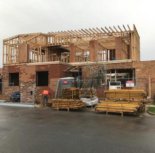
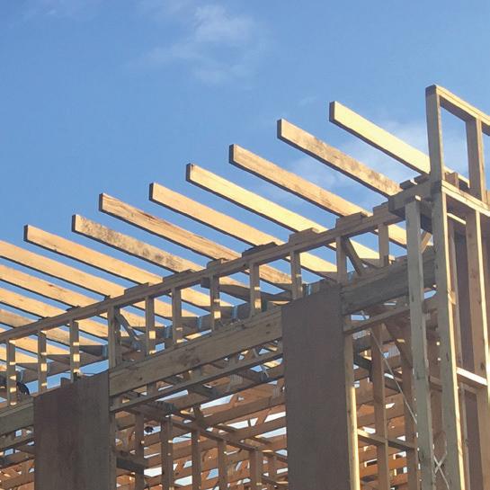
• Small and large Scaffolding are used to reach the roof level.
Rafters according to the photos. Possibly due to angle misalignment between the roof frame and prefabricated Truss during construction.
• Thermoseal reflective foil Roof Sarking is installed first before insulation to provide protection against rain during installation process. It is used to prevent condensation, by transferring water to gutter along roof. [Insulation, p.2]
4.1 • Compressed Fibre Cement Sheet is placed on top of the Ground floor Rafters - balcony area. [External Finishes, p.3]
4.2
• Flexible Polymetric Membrane is applied to the balcony, over the existing Compressed Fibre Cement Sheet.
5.1
• Place Gutter Board to fully support bottom of Gutter along its entire length.
5.2 • Flatsheet Profile Box Gutters from Colorbond are installed, to allow water flow off the roof into Down Pipes. They are concealed by Parapets for aesthetic purposes.
5.3
5.4
• Rainwater Head with Pop Overflow.
The Rainwater Head itself is installed at the top of a downpipe to collect water from gutters.
The Pop Overflow is an outlet or opening near the top of the rainwater head to let excess water spill out safely if the water level inside it ever gets too high. This is can prevent water backflow into the Gutter or dealing potential damage to the roofing system.
• Installation of Concealed Down Pipes (CDP) between the studs. The exposed Down Pipe (DP) is connected to the Rain Water Head (RWH).
The releasing end of the CDP is buried under slab, which was settled in Stage1.
• Steel roof, Spandek model from Lysaght, in ‘Colorbond Monument’ shade. The sheets are 700mm in width, 24mm thickness, various length. Each sheet slightly overlaps with another, and is always installed from left to right, bottom to top so that water does not flow into the building. [NCC 7.2.6]
• They are fixed to steel support through the crest only, using screws: Typically three threads on a screw need to be visible after protruding past the steel support to meet the penetration requirement.
**Steel Support: Not specified in the Architetcural document, and is only present on G level roof. The Shank Protection on each screw however, must not reach the steel support.
• The end result has a 4 degrees fall, following the shape of the Roof Trusses for better rainwater flow.
• Apply Roof & Gutter Silicone Sealant to any Gutter joints, to block water from entering cracks or damaged areas, thus preventing water damage to the house.
Roof Truss R.T The Truss consists of a Top Chord, Bottom Chord, and Webbings in between. Although unspecified, the Trusses are likely to be using 90x45MGP10, except for the Top Chord that is 140x45 of the same material.
Top Chord Truss (closest to the east)
BRT 140x45 Laminated Veneer Lumber.
It is used to support the weight of the roof. The Webbing is used to enhance its strength.
Provides roof profile and service space.
For more capability to support the Cantilevered Rafters. N/A
Cantilevered Rafters N/A 140x45 Kiln Dried Hardwood, 450centres. 1000 overhang, 1200 back-span. Connected to Truss Top Chord {BRT} using Pryda Joist Hangers. They will allow the roof to have a continuous extrusion over the balcony.
They allow for a more geometrical design outcome.
733MD Thermoseal reflective foil Roof Sarking
Compressed Fibre Cement Sheet
N/A Type: 733MD. It is a non-permeable vapor barrier.
CFC: CF11 18thick from HardiePanel.
Flexible Polymetric Membrane
N/A From Fastflex. Fastflex is a fast-curing, polymer-modified waterproofing membrane made of tough cement.
Lysaght Spandek RF01 700 nominal cover width, 24 rib hight. Shade: Colorbond Monument’.
It reduces moisture entering the home. When placed next to an air cavity, it also adds insulation to the roof.
The product is recommended for warmer climates, where they help block radiant heat.
Functions similar to a Particleboard Sheet (see previous page), but is typically used for flooring, external decking, wet areas, and cladding due to its durability and resistance to moisture and fire.
N/A
While is has the same waterproofing quality as a Membrane Sheet, it is first applied as liquid, allowing it to form a seamless, monolithic membrane that bonds well to the substrate and adapt to irregular surfaces. Once cured, the liquid polymer will form a rubber-like layer that is highly flexible, making it resistant to weathering and cracks; suitable for balcony.
N/A
This squar-corrugated profile allows for a contemporarylooking outcome, while being lightweight and rigid. The chosen shade is a deep grey, that is one of the most accomplished shade from the series. It is aesthetically suitable to timber and white colour.
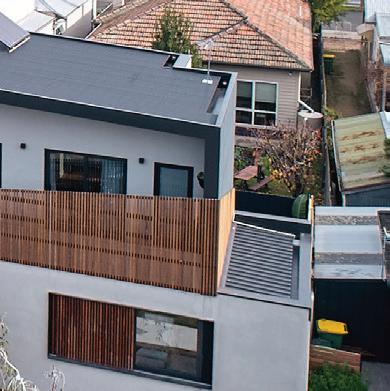
Image from the final photos. Showing the Gutter, Parapet and Roof cladding. Smooth transition from the Box Gutters to Parapet Capping.
2.3.1
2.3.2
2.3.2.1
2.3.3
• Flat Sheet profile Flashing from Colorbond. They are used to direct water away from at-risk areas (such as where roof meets the wall), and allow it to flow off the roof into the Gutter.
• The Flashing itself should either be covered by a vertically running membrane, or soft aluminium/zinc for the same reason.
• Articulation Joints [AS4773.1] is constructed during the process to allow slight movement of the building to avoid any cracks in case of thermal change in the foundation.
• A small piece of Backer Rod or compressible foam is tucked into the joint during installation, and use Flexible Sealant in front of it to fill the cavity of the Articulation Joints. [NCC 5.6]
• Weep Hole -- a small opening is created between bricks, close to the ground. They prevent structural damage to the property due to moisture and rot, by improving drainge and ventilation of the cavity. Any moisture within the cavity will also be released through the Weep Hole.
An Open-Weave Mesh may be placed in the cavity during brickwork, to prevent fallen mortar from blocking the Weep Hole. Weep Hole Protections are often applied as well, to still allow air and water flow but prevent pests nesting in the cavity through the Weep Holes.
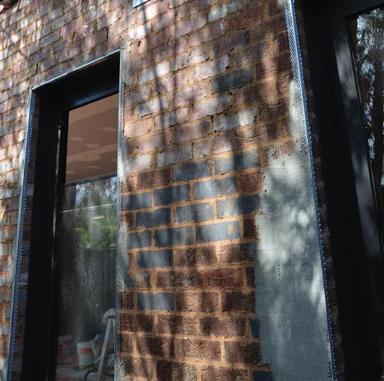
• Approximately Natural Cement Render is applied to the brick facade on Ground floor mostly for asethetic purposes.
• A Fibre Cement Base Sheet is applied to the1st Floor as external cladding. [CD4-04, WT05]
Parapet Capping
• It is an alternative form of metal Flashing for the parapet wall. It is installed to waterproof and protect the ends of vertical sheets, claddig, membrane, etc., from water.
• If the Capping is fixed using screws, they must penetrate horizontally from the sides, to effectively seal the parapet without leaving small gaps on the top for water to fall into.
** Since the Cappings need to cover the brick cladding once it is complete, it occurs at this stage instead of Stage 3.
Timber Facade and Blustrade
• Installation of Spotted Gum Timber Facades [External Finishes, p.3]
• The battens are then painted with Cutek Colourtone Oil, shade ‘Sela Brown’ for aesthethic purposes. 6.1.1
• The Facade comes with aluminium bars are to be attached to the masonry wall.
• Once the battens are ready, they are clicked onto the aluminium bars for aesthetic and/or privacy purposes.
• Standard grade Spotted Gum Decking The
and
• Before installation, the timbers are also treated with two coats of Cutek Wood Preservative - CD50. Same function as mentioned previously.
**Substages 7.3-7.4 apply to the Balcony only, following Stage3 Roof/Upper-roof Covers:
• Ceremic Floor Tiles are placed on top of the Flexible Polymetric Membrane for aesthetic purposes.
• Adjustable Pedestals from Buzon to support the Deck Joists. They allow the Decking to have a leveled finish, while the Balcony itself has a 4 degrees fall for water flow.
nails are required to be driven into the wood with the heads leveled with the surface of the decking, without protruding above or being sunk too deep. This ensures a smooth end result with no damage to the timber or tripping hazard.
Breathable Wall Sarking N/A
Enviroseal RW from Bradford. It is a light duty vapour permeable wall wrap.
It is used to reduce airflow around insulation to make it work more effectively. It can also defend the internal wall from weather-related water damages. The fact that this product is vapour permeable reduces the risk of condensation build-up and mould growth in the timber frame.
N/A
Brick Veneer Wall N/A Each brick is 230long, 110thick, 76high.
Non-structural. Provides great level of passive thermal and sound insulation. Naturally fire-proof and weather-proof. It is versatile for re-decoration. In this case, it is used to support the layer of Cement Render. It is also sustainable and affordable.
Fibre Cement Base Sheet N/A Board from HrdieTex. 7.5thick. It has a similar Cement Render appearance, without the weight/need for masonry.
Allows for a consistent wall finish across both floors, by pairing it with Cement Render -- same way as the Brick Veneer Wall.
Natural Cement Render EF02 10thick. Grey colour. Protects and enhances Brick Veneer Wall adhesion. Contributes to insulation.
Creates a smooth external surface, and the colour is chosen to suit the building’s palette.
Triple Sliding Door D/G-2 Doubled glazed, laminated.Aluminium frame. + Insect screen.
U-value: 3.9 = moderate insulation; which could result in more heat loss in winter and heat gain in summer. SHGC: 0.63 = moderate-high solar heat transmission; which can be beneficial by allowing more sunlight in. This can potentially offset the impact of the moderate U-value in winter.
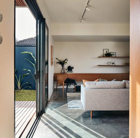
A clear, wide sliding door connects the house to the backyard decking, while providing good view. The insect screen allows better ventilation experience in summer (evenings, especially).
Sliding Door D/1-2 Doubled glazed, laminated.
Aluminium frame.
+ Heavy guage security mesh.
Inward-opening Door D/1-3 Doubled glazed, laminated. Aluminium frame.
+ Translucent glass.
Tilt & Turn Window W/G-8
Doubled glazed, laminated.
Aluminium frame.
+ Insect screen.
Fixed Window W/1-1 Doubled glazed, laminated.
Timber Batten Sliding Screen
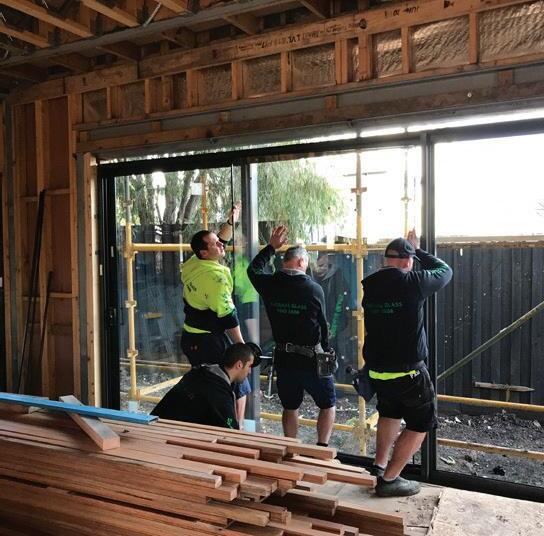
Sliding Door installation. The
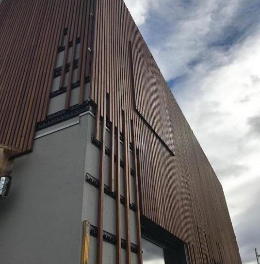
Application process of the Timber Facade. Uneven lengthed battens are clipped to the aluminium bars. This image also shows how the window screens blend with this appearance.
Timber Batten Fixed Screen
Aluminium frame.
S/G-3 Vertical Spotted Gum timber battens, 42wide, 32thick, 25spacing.
50 Square Hollow Section frame.
S/1-1 Dimension as above. Fixed to 32x32 horizontal battens at the top and bottom of a steel frame. The steel frame itself is fixed to the stud wall.
Same as above.
A clear sliding door between upper floor bedrooms and balcony, allowing smooth access and good view. Security mesh is used to enhace safety. Its bottom frame edge fitted to the slab with rebate, so that it creates a smooth and triphazards-free area.
Same as above.
A narrower single door between upper floor storage and balcony. Translucent glass can make the room look less clustered from outside.
Same as above.
A square window in the living room, facing the street. It can be opened fully or partially (in rainy days) for ventilation; both ways are insect-proof.
Same as above.
A narrow window on the upper floor looking North. Used for sun intake.
Paired with W/G-8.
Allows view when fully opened, and privacy when closed. The battens also blend with the building facade due to the same use of material and dimension.
Paired with W/1-1
Similar to above. Provides shading and privacy to the house. Also prevents over-looking the neighbour.
Spotted Gum Timber Facade EF01, standard grade Dimension as above. Product from ConceptClick. N/A Used for athesthic purposes.
Spotted Gum Decking FF11 86wide,19thick, various length, 5spacing.
Standard grade Spotted Gum has great duraibility and hardness. It is also fire and weather resistant. Suits the overall timber motif of the house.
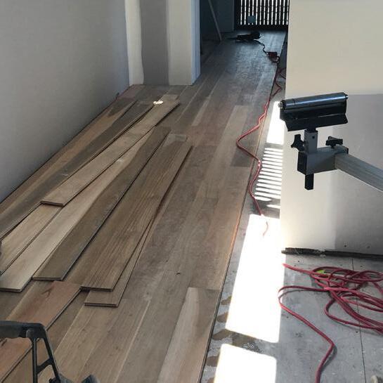
• Red rosin paper (heavy duty recycled felt paper) may be used to protect indoor floors from scratching and spills.
•
•
•
•
•
so the power is sent downstream.
• Staple the wire to the studs along the way.
• Take the sheathing off the wire groups, then strip each wire.
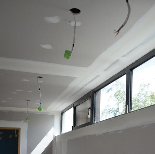
• Leave the Live (brown) and Neutral (blue) wires to the side, fit the two Ground (Green&Yellow) wires through a Crimp Sleeve. Close the sleeve and twist the wires tightly. Trim one of the wires and bend it back, leaving only one Ground wire available. When a box contains more than two sets of wires, it is recommended to use Pigtails (a cap over two wires) rather than performing Through Wire, so that a problem or loose connection will not affect any outlets downstream.
• Fold all wires inside the box, to be properly connected to devices in later Stages.
**Some ceiling wires appear connected to a green outlet in photos. They may be conversion ports for older light models, since all lights are supplied by the client.
• The inspection takes place now to ensure that everything is in order, and secured.
•
•
• Use laser to mark the desired ceiling height.
•
•
• Clip the Furring
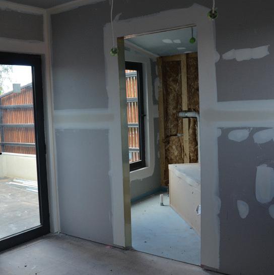
• Plasterboard applied to all internal walls and ceilings as per AS2588.
• Fixed to the top, bottom plate and noggings at 150 centres; 300 centres to the studs.
• Plasterboards are cut up to fit
• Plaster jointing on small cavities and imperfections caused by the screws:
•
•
• Smooth with sandpaper once dry; if needed.
Name Code Description (units in mm)
Glasswool Roof Insulation N/A
Made of Glasswool -an insulating material made from glass fiber. 260thick.
Building Performance & Design Intent
R6.0. Placed around Roof Trusses to poviding a very high level of thermal regulation between indoor and outdoor. This insulation with R6.0 must be applied along with foil sarking, too meet the ceiling insulation requirement. [Energy Report]
Placed around Roof Trusses. It reduces heat transfer to keep the building at an ideal temperature all year round. It also contributes to soundproofing and fire resistance.
Same as above.
Combined with the foil sarking, this insulation will allow for great energy efficiency inside the house. Gold Hi Performance Ceilin Batts N/A
Gold Wall Batts N/A Made of Glasswool, 90thick.
Gold Hi Performance Wall Batts N/A Made of Glasswool, 140thick.
Acoustic Wall Batts N/A Made Polyester, from BradfordPolymax, 90thick, R2.5.
R6.0. Poviding a very high level of thermal regulation between levels.
Provides high insulation quality to the Ground floor ceiling, since good ceiling/roof insulation can save up to 45% or more energy costs.
R2.5. Providing a low level of thermal regulation. While the R value is low for external walls, it should be sufficient, as the Brick Veneer also contributes to insulation.
R4.0. Used for the Upper floor weastern wall only. Increased thickness to guard against the west sun. A 90thick External Wall insulation [WT05] is stacked on top as space filler, to also saves material.
Thermal and acoustic ceiling batts. It is used around the Storage.
Functions in a very similar way as Glasswool Wall Batts, but further minimises noise transfer between rooms and levels. While the Storage does not require soundproofing, it is a conventional pratice to apply acoustic qualities to the internal walls.
Plasterboard CF01 10thick, likely to be 2950high. Nominal width can range from 600, 900, 1200 to 1350.
Contributes to good thermal and acoustic performance of the house.
Creates a smooth finish to the internal walls, for paint to be applied in Stage6.
Tracklight TRK Provided by Light Project Provides illumination.
A row of small spot lights. Used to possibily highlight the living room as it is the main social area.
- Pixel 2
Provided by Light Project **company website could not be accessed.
Small spot lights that illuminates the space relativly evenly and gentally.
External Wall Light EWL Provided by Light Project Same as above.
Double General Power Outlet GPO Slimline SC2000 series from Clipsal. White colour.
Provides warm lights to the balcony in an hourglass-like shape (according to the photos).
Double outlet with two switches. Mounted to the walls behind the TV cabinets for electricity.
•

Paint WF01
One coat of Resene
Broadwall Waterborne Wallboard Sealer, then two coats of Resene Zylone Sheen Zero VOC.
Delux ‘Natural White’ shade.
Repel Penetrating Sealer from FF01 Product from Crommelin.
N/A
Low sheen finish.
Used for the Burnished Concrete Floor finish. Creates a surface that is resistant to chemicals and staining agents, also inhibiting mould and algal growth. Creates a satin finish. Natural Oil
for
Reinforces the colour and texture of the timber, creating a clear, matt finish.
Timber Veneer (joinery material) JF01 True Grain Natual Blackbutt. From Briggs Veneers.
Medium Density Fibreboard (MDF) from JF01 18thick MDF E0 board from MR. Used under the Timber Veneer.
Water Based Finish from JF01 2 pac polyurethane paint. 30% satin.
Undyed wood veneer, suitable for interior, dry and lowmaintainance applications. N/A
E0 rating for low formaldehyde content, to obtain ‘Good Environmental Choice Certificate’. N/A
Enhances wear and scratch resistance, prevents discolouration.
Gloss finish, also making it easy to clean.
Blinding Concrete
Engineer Fill
Sandbag
Trench Mesh
Square Mesh
Rebar
Edge Beam
Stiffening Beam
Pad Footing
Slab
800mm deep
200mm deep
25mm thick
Q1: How have the existing site conditions and context informed the design of the house? What site-specific design choices have the architects made to respond to the existing site conditions and context?
According to the Soil Report, the Northcote House site is classified as Class P (problematic) due to its abnormal soil moisture conditions. While a standard soil profile typically exhibits a surface movement range of 75mm, the abnormal soil at this location may result in increased or unpredictable surface fluctuations.
To address these conditions, the foundation was decided to have a bearing capacity of 250kPa, appropriate for supporting a double-story structure. To meet this requirement, the foundation material needs to penetrate 600mm into the silty clay layer that is a more stable base. To further ensure the footing’s proper placement and enhance its overall stability, a 15MPa blinding concrete layer has to be poured first, ensuring the footings are supported at the required depth to overcome potential soil movement. continues... ......
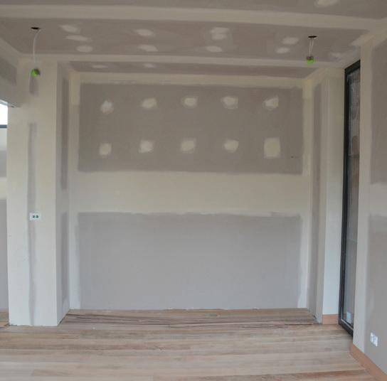
In addition to the foundational challenges, the site itself is spatially limited, covering only 377 square meters. Furthermore, an existing easement runs along the boundary, restricting any solid structures from being built on top of it yet allows for shallow pathways or driveways. To maximise the usable area, the architect extended the ground floor decking, creating a flush transition from the living room to the easement. This design choice effectively expands the usable living space, making the house feeling more spacious without violating council restrictions.
Waterproofing
Membrane
Screed
Hydronic Heating Pipe
Insulation Mat
The coiled Pipes are connected to a manifold, providing concentrated warmth though the heating up the thermal mass (Screed). This system is suitable for stabling temperatures long term, resulting in a comfort environment.
The Insulation Sheet is used to create enhance thermal break for a better result.
Engineer Fill is piled as multiple rectangular dunes, each with a layer of compressed Sandbag on top. Together they creat a formwork to mold the footings, as well as providing additional support to the slab.
300mm wide x 600mm deep
600x600x600mm
130mm thick
0.2mm thick polyethylene film
100mm thick concrete
28mm diameter coiled pipes connected to manifold
37mm thick polystyrene Insulation Sheet
Beams and Footings are laied out in crosses to support the load from below, prevting deflection of the slab. Pad Footings especially are used to carry concentrated load from columns.
All structural componants are linked together with the Concrete Slab with a smooth surface.
Rebar and Meshes are embedded to the footings and slab to enhance their stength.
The film is placed over the Sandbeds to prevent moisture entering the Footing and Slab.
2/90x45 MGP10 (Double Stud - L1)
2/90x45 KDHW (Double Stud - G)
Carries both dead and live loads; critical to building stability
load bearing but completes the Primary system
Bracing are essential for stabilising the timber structure during and after the building process. It provides lateral support to prevent buildings from swaying or compressing under loads within the building, as well as external forces such as wind.
90x45 common stud timber
190x45 MGP10 @600CTS
2/240x45 MGP10
89x89 SHS
298x149 300UB
200x75 200PFC
300x90 300PFC
190x45 KDHW @450CTS
140x45 MGP10
140x45 KDHW @450CTS
Q2. How do the structural systems help to support the design intent of the house? Why is the structural design appropriate for this house?
The building is mostly built with timbre framing for its lightweight and cost efficiency, which is a common system for residential building. Meanwhile, steel structures (columns and beams) are also incorporated, by first welding the square hollowed section to the footing, then embed it as replacement of some timber studs. The columns then support the horizonal beams, which carries the upper floor weight. The enhanced strength of the building will allow for more design incorporations such as a large balcony, balustrade, second skin, etc. In addition to having grater load bearing capacity, the steel structure can better support a larger space. This can solidify the architect’s intension and motif in creating flush areas with little boundaries in between, that contributes to both atheistic and accessibility. Especially for the ground floor living room, the parallel flange channels together with universal beam support this ideology, leading to its present design. Furthermore, the hybrid use of steel and timber framing can also create a more geometrically interesting details, such as overhangs. Once again, this links to the architectural goal to creat ‘flow’.
140x45 MGP10 @600CTS
140x45 LVL @600CTS
19mm thick Yellow Tongue
30wide
Top chord on the Eastern truss is replaced by LVL to better support the cantilevered rafters. The Truss system provides roof profile and service space.
reinforcement system. They
of
top and bottom chord at a specific distance, with reticulated webbing in between for reinforcement, to mimic the effect of an Universal Beam while remaining lightweight. The webbing also leaves more space between the chords than a Timber-Strut, that is beneficial for future roof/structure maintenance. Primarily used for interior flooring especially on the first floor, providing a stable base for floor coverings in dry areas.
by
Rafters in general are used to support the roof wright. Cantilevered rafters especially allows the roof to have a continuous extrusion over the balcony, thus a geometrical design outcome.
Steel structure is used cooperatively with the timber. Beams are either welded to the column or fixed to each other. They are more effective at transferring load downward. The Universal Beam especially allows the architect to design a large space without studs in between.
Sarking/Membrane
Flexible Polymetric Membrane
Q3. How does the design of the house incorporate environmental protections? Are they expressed as part of the architecture or are they presented more iscreetly?
Environmental Protections
Acoustic Waterproofing
Wall Cavity
Breathable Wall Sarking (Bradford)
30mm between Membrane and Brick
Weep Hole
Thermal Comfort
Gutter
Rain Water Head
Pipe
Roof Sheeting
Flashing
Capping
Fibre Cement Sheet
Greenboard
Insulation
Acoustic Wall Batts
Consistent use of double glazing, providing protection against weather as well as thermal comfort that introduces natural ventilation and heat resistance.
Insulation is thoroughly applied to the house, as they provide comfort by reducing heat tranfer and/or loss between the interior and exterior. Different thickness are used depending on the performance needs: R4.0 insulation is used for the upper floor West wall only to guard against the west sun. Their thickness may also be grealy redued near upper roof area to save material. While insulations naturally contribute to acoustics, more specific types are used to target this aspect.
Brick veneer wall in this case is mostly used for the final aesthetic, but it also has protection qualities. By sitting on the rebate, slighly away from the stud wall, its cavity can stop moisture from entering the building. Together with the weephole, any moisture within the cavity will also be released, enhancing its function.
Opening between bricks near ground
Flatsheet Profile box gutter (Colorbond)
With pop-overflow
100mm diameter, to RWH
700wide x 30thick Spandek (Lysaght)
Flatsheet Profile (Colorbond)
N/A
90x45 LVL @450CTS + steel webbing
7.5mm thick (HardieTex)
75mm thick NRG Greenboard
Sliding door Inward-opening door
Tilt & Turn window Fixed window
260mm glasswool
Gold Hi Performance Ceilin Batts
140mm glasswool
Gold Hi Performance Wall Batts
90mm glasswool Gold Wall Batts
230x110x76
90mm polyester Acoustic Wall Batts (BradfordPolymax)
Sarking is used to reduce airflow around insulation to make it work more effectively, which also prevents condensation.
The metal roof sheeting is stacked to form a slop, whch not only completes the building profile but also directs the water to the ground.
Flashing is installed to at-risk areas, such as where roof meets the wall. It then allows water to flow off safely into the gutter.
Everything above links to the gutter system, which is protected by the capping. passes water to the down pipe through the rainwater head. The Rainwater Head itself can let out excess water, preventing backflow into the Gutter.
Fibre cement sheet and greenboard are cladding alternatives that complete the facade. While fibre cement sheet is more resistant to moisture, greenboard provides extra insulation qualities to enhance the termal comfort.
The Northcote House demonstrates a detailed approach to environmental protections, particularly in terms of water management and heat proofing. Water flow is carefully directed through a cohesive system that begins with the sloped roof, guiding water into the membrane and flashing, and finally channelling it into the drainage pipes. This layered strategy ensures that the building remains well-protected under any weather, preventing potential damage to the structure.
The use of various materials and insulation types is also well considered to suit specific needs within the building: such as the thicker insulation applied to the upper west façade, as it is exposed to greater solar heat gain. Furthermore, variation in materials also reflects the architect’s design intent. The non-structural brick veneer wall, though offering little in terms of thermal insulation, is employed extensively for its aesthetic value, that can be rendered later. On the upper floor, fibre cement sheets are used, continuing the visual appearance of a cement render but in a lightweight form, connecting all levels in appearance. The strong emphasis on aesthetic goals means that environmental protections are integrated discreetly. Gutters, for example, are concealed by parapets and capping, maintaining clean rooflines without visible drainage elements. Multiple downpipes are also hidden between the stud wall, contributing to the house’s sleek and minimalistic exterior. This strategy achieves a contemporary look while ensuring the building is still highly functional.
Lighting components are placed around the house and different types are used depending on the location.
Small spot lights (Pixel 2) are most commonly used as they illuminate the space relatively evenly and gently.
External wall lights are installed to the exterior wall, providing warm glow to the balcony in an hourglass-like shape
Rows of tracklights are used in the ground floor living room to possibly highlight the living room as it is the main social area.
Q4. Are the spaces arranged to optimise the efficient use of building services? What design techniques are used to integrate services in the design of the house?
Being the closest portion of the plan to the electricity pit on site, the architect takes advantage of this position by accommodating dry areas that require more electrical devices. As a result, the living room, bedroom, and storage are clustered in this area, allowing for efficient electrical distribution. This arrangement ensures that electrical services dominate this part of the house, creating a well-balanced and consistent application of power. For the living room in particular, this setup enhances functionality, providing ample illumination and the convenience of multiple double power outlets, along with network and TV connections for modern living needs.
Additionally, the integration of a hydronic heating system under the screed on the ground floor complements the electrical design by contributing to the home's overall energy efficiency and thermal comfort. However, the same approach could not be applied to the upper floor, where timber flooring is intended. Hydronic heating directly under timber could cause warping due to frequent temperature fluctuations. To resolve this, hydronic heating panels were installed in the upstairs bedrooms instead, which is an effective solution, maximising the benefits of the hydronic heating boiler while maintaining the integrity of the timber flooring, expanding thermal comfort to both levels.
The hydronic heating under screed is a water-based heating system operating though manifolds, that is powered by gas. Concealed down pipes installed between studs. Releasing end is buried in the slab. Allows for desired aesthetic outcome. Despite being visually pleasing, this system can be risky to build as any inadequecy during installation will result in severe water damage to the house.
90mm, R2.0. Low level thermal regulation. Relatively thinner insulation possibly due to the the spacing with the brick veneer wall.
260mm, R6.0. High thermal resistance. Used with Thermoseal Reflective Foil roof sarking which further reflects radiant heat.
140mm, R4.0. Better performing insulation for the upper level west wall only; accommodating the sun orientation.
Uniformly have 3.9 U-value and 0.63 SHGC. Both values are moderat to poor in performance, which can result in heat loss.
Suitable for general and focused lighting use.
Ambient and aesthetic application.
Directional and ambient lighting, used in more open areas such as the living room.
These pipes flow to one hydronic manifolds, then get pumped to the heat source being a natural gas boiler. Create even tempture for large open spaces.
A non-structural concrete slab that has high thermal mass, great for absorbing and releasing heat.
Mainly for decorative purposes with decent soundproofing.
Provides controlled shading and glare, while allowing for ventilation.
Large sized window and doors placed on the east and west sides only.
8: The hydronic system is appropriate especially when sharing the same manifold and boiler between the heating pipes and panels. While using gas boiler is already the most popular and quick heating solution, it can be changed to electric based air-to-water heat pumps for more energy and cost efficiency. The terminal unit may also be upgraded to those more compatible with lower water temperatures, to increase the operating efficiency.
9-10: As suggested for [5-7], increased glazing will allow the concrete screed to receive better direct sunlight and radiant heat, better utilising its thermal mass properties. Similarly, reversing the brick veneer wall to the inside of insulations will also allow it to absorb and store heat from sunlight during the day, and releases it slowly at night, thus helps to maintain a more stable indoor temperature.
11: The timber battened screens are effective, but their frame and/or overhang material can be changed to wood, fibreglass, and uPVC for less heat conductivity. If the existing aluminium cannot be replaced, adjusting it to be thermally broken will also result in a better thermal insulating quality.
12: Installing windows on the north side can be challenging due to the need to avoid overlooking the neighbor's building. However, it may be possible to add more west-facing windows with good insulation values on the upper floor to promote cross ventilation without overheating the room.
Q5. How would you redesign aspects of the house to improve its energy efficiency and comfort? Consider passive design principles and active strategies.
1-3: The thermal performance of wall insulation can be enhanced by reversing the existing brick veneer walls, if not by increasing the insulation thickness. Currently, 260mm insulation is applied only to the ground floor ceiling, while the roof uses 90mm of standard insulation. By applying the 260mm insulation between the roof trusses as well, heat loss through the roof can be significantly reduced, potentially saving 45% or more in energy costs. 140mm west insulation on the first floor has effective performance that directly responds to the site orientation and client’s needs, but extending its range to the entire west wall can enhance such performance.
4: Despite being double glazed, the existing glazing panels are only moderately effective at thermal insulation. Triple glazed window with thermal bridge may be a better replacement.
5-7: Relatively small sized lights are used widely and evenly across the space, providing soft and pleasing illumination. However, more natural sunlight can be introduced to the house by expanding the glazing area on the eastern façade. continues...
As metioned previously, the roof cldding completes the profie. Its chosen shade is a deep grey, that is aesthetically suitable to timber and white colour, and corresponds to the nearby charcoal paint.
Q6. Do elements of the physical enclosure and
form express the programmatic functions of the house? Give examples where form or materiality might relate to a specific programmatic function within the house.
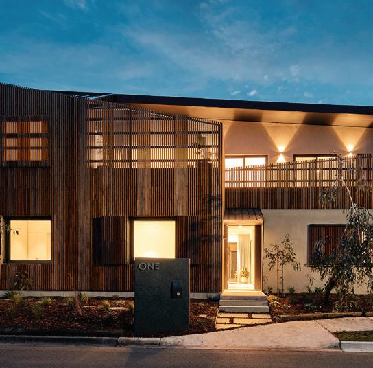
The physical enclosures all together, create a striking modern facade, that is relatively rare for a residential building. The chosen colour palette is brown, dark grey and white, that is a visually pealing pastel scheme, enhancing the character and texture of the building exterior.
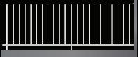
On top of the aesthetic planning, enclosures of the building also contribute to enhance living quality. While timber battens are used for decorative purposes, this appearance is recurrent throughout the architectural form. Due to the presence of small children in the client’s family, the balcony balustrade has to be greatly increased to prevent falling hazards. Because of this, the timber batten motif comes into play, creating a physical barrier as fencing, while still allowing for natural light and ventilation to the upper floor. Similarly, the same system is used for window screens that may even be operable, to provide shading or reduced glare, softer airflow as well as privacy to the building.
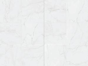
Burnished concrete floor finish is applied to the screed, resulting in a polished surface that is durable and easy to maintain for the living room, that is the main gather area in this building. Its grey satin finish also suits the overall colour scheme, drawing connection to the footing system, and enhancing the minimalistic design concept. While the texture can give a harsh and heavy impression, it juxtaposes with the timber flooring upstairs, to invoke coziness and comfort through contrast.