ARC3016
Detailed Design Report
Student: Yaoxuan Zeng 210512715
Project: Benwell Community Art Centre, Benwell, Newcastle upon Tyne
Tutors: Kieran Connolly, Ellie Gair
Studio: Studio 7 Loose Fit
Student: Yaoxuan Zeng 210512715
Project: Benwell Community Art Centre, Benwell, Newcastle upon Tyne
Tutors: Kieran Connolly, Ellie Gair
Studio: Studio 7 Loose Fit
1.Project Declaration p.3-23
Site Layout p.3
Site Photo p.4
Site Plan p.5
Building Plans p.6-9
Key Sections p.12-13,16-17,18-19
Key Elevations p10-11, 14-15,20-22
Material Palette p.23
2.Thinking Through Making p.24-27
3.Structure p.28-31
4.Sustainability and Environment p.32-51
4.1 Biodiversity p.32
4.2 Green Infrastructure p.33
4.3 Water Use p.34-35
4.4 Form Factor p.36
4.4 U-Value p.37
4.5 Sustainable Materials and Embodied Carbon Strategy p.38
4.6 Heating and Cooling Diagrams p.39
4.7 Sun Angle and Shading p.40-41
4.8 Ventilation Diagrams p42-43
4.9 Building Services p44-51
5.Fire p.52-65
5.1 Horizontal Travel Distance p.52-54
5.2 Escape Stair Design p.55-58
5.3 Exit Routes and Places of Safety p.59
5.4 Access for Firefighting Appliances p.60-61
5.5 Structural Fire Protection p62-64
5.6 Compartmentation p65
6.CDM and Risk p.66-68
7.Assembly p.69-72
7.1 1:20 Detailed Section, Part Plan and Part Elevation p.69-70
7.2 Three Stages of Construction p.71-72
7.3 Description p.72
Appendices p.73-75
Site Layout from Semester 1 p.73
Material Palette from Semester 1 p.74
Building Structure from Semester 1 p.74
Heating and Ventilation from Semester 1 p.75
Fire and Life Safety from Semester 1 p.75
List of Illustrations p.76-79
Referencing p.80
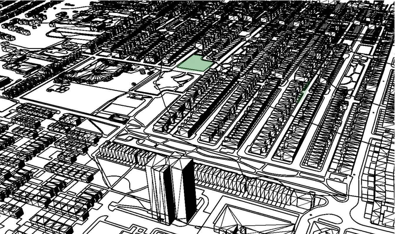
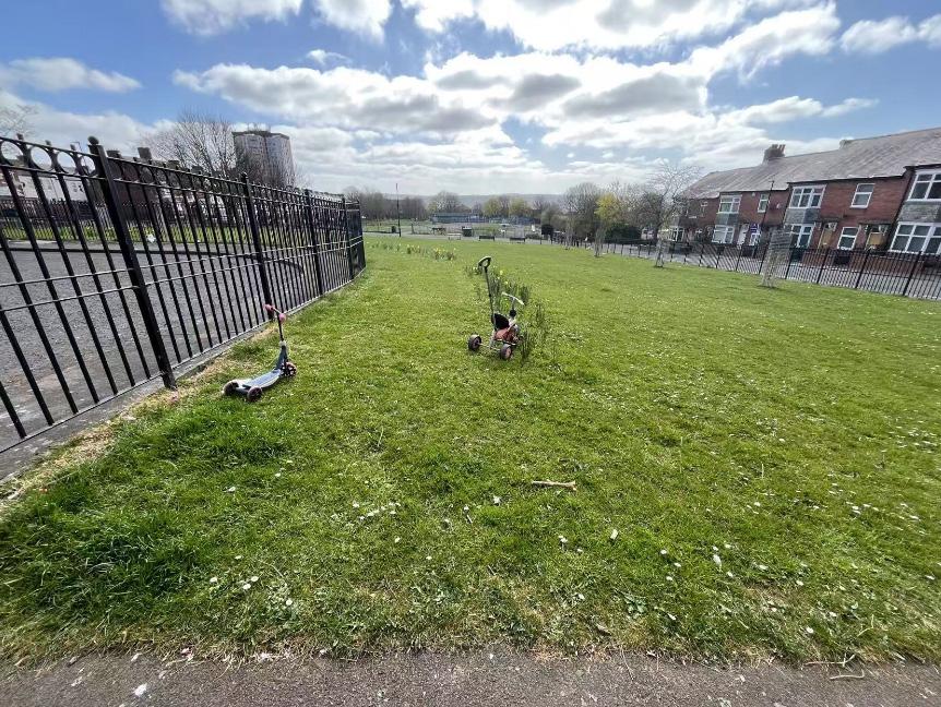
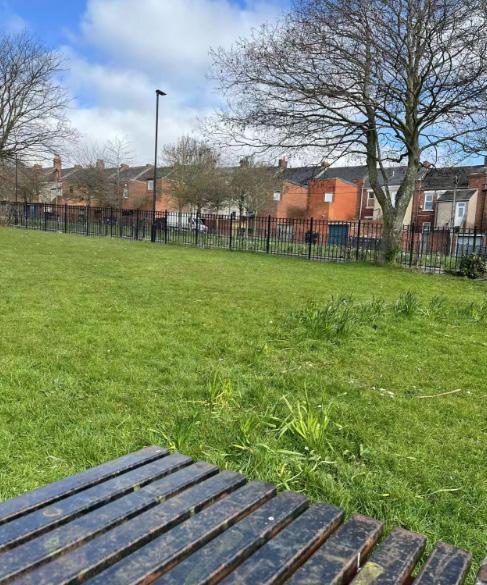
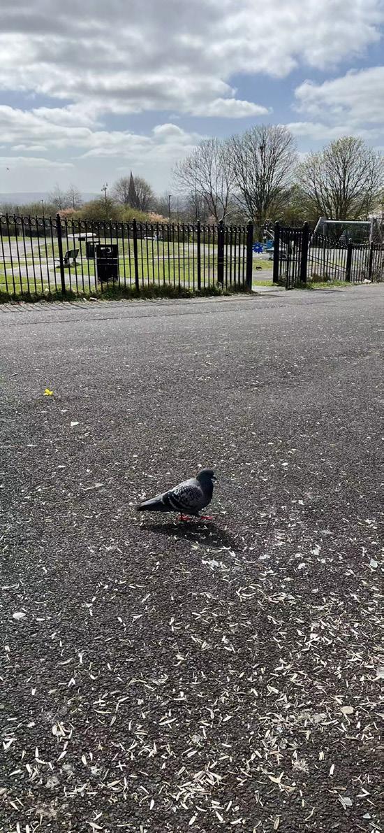
My chosen site is located on a large grassland with a two-metre height difference, just two blocks north of the main street-West Rd, adjacent to a primary school to the southewest and the area’s largest public playground to the south, and surrounded by a large residential neighborhood.
When entering from the main entrance at the north, you could see reception on your left,connecting the office and meeting room for staff.
When you turn right you could have a rest at cafe and playspace or buy food and drinks, served by the kitchen nearby; or perhaps you've already bought tickets for an exhibition or performance, so that you prefer sitting in front of Event Space, the biggest flexible space in the building, to wait for the door to be opened. It is a 6m-height space being able to accommodate both visual arts and performing arts activities.
Artists, sometimes with invited public members, who produce large installations in 5m-height art workshop located at the southeast of building, or practice their choreography at the rehearsal room located at the northeast of building, or wait at the dressing rooms,can quickly travel to Event Space by a private corridor and two private-access doors. A designed lounge are there for them to have a good rest.
BIf you come from the south of this site, you could either enter the building through the side entrance; or through the commuinnty garden with accessible ramps and stairs with a direct access to cafe. If you turn right at the foyer you could see two art classrooms. Plarfom lift and staris leading you to public toilets and event space after the fire door were designed for travelling though the two metre drop on site.
First Floor Plan 1:200
On the first floor, there are two single rooms and two double rooms with associated laoundry,communal kitchen, living and dining for six artists staying here. Flats are located at the east and north side of the building to avoid southwestern strong wind.
Art studio, with the best sunshine experience on this floor, is privately used for artists living in both first and second floor, being a peaceful space for them to have any kinds of artistic communication and collaboration with each other.
Second Floor Plan 1:200
On the second floor, another two single rooms and two double rooms are provided for artists, so as laundry, communal kitchen, living and dining.
An open-air balcony could let people enjoying sunshine and fresh air together.
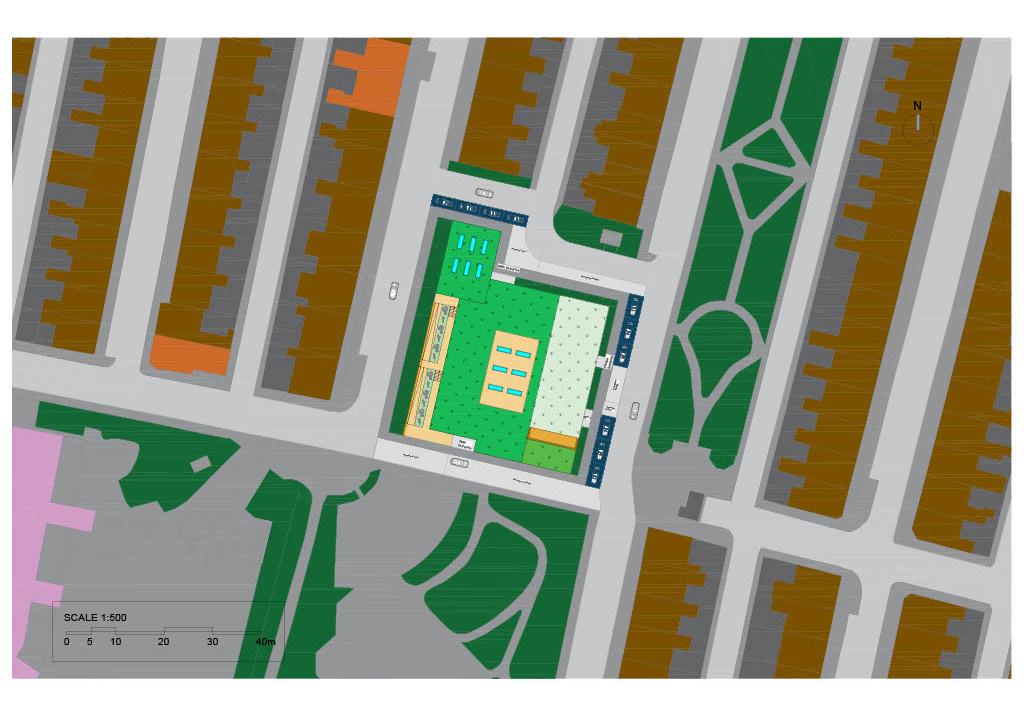
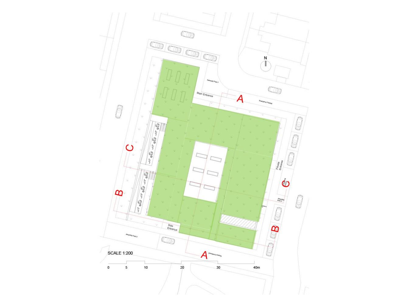
Roof Plan 1:200
From the roof plan you could see the open-air garden at the southwest of building, skylight for ground floor cafe at the northwest of building, skylight for double-height event space, second floor balcony at the southeast of building, and most importantly, a large area of green roof, space to achieve greening rate and realise building heat dissipation.
Long Section A-A 1:200
South Elevation 1:200
5 10 20 30m
SCALE 1:100 5 10 20 30m
1:100 5 10 20 30m
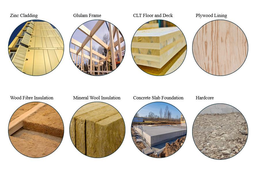
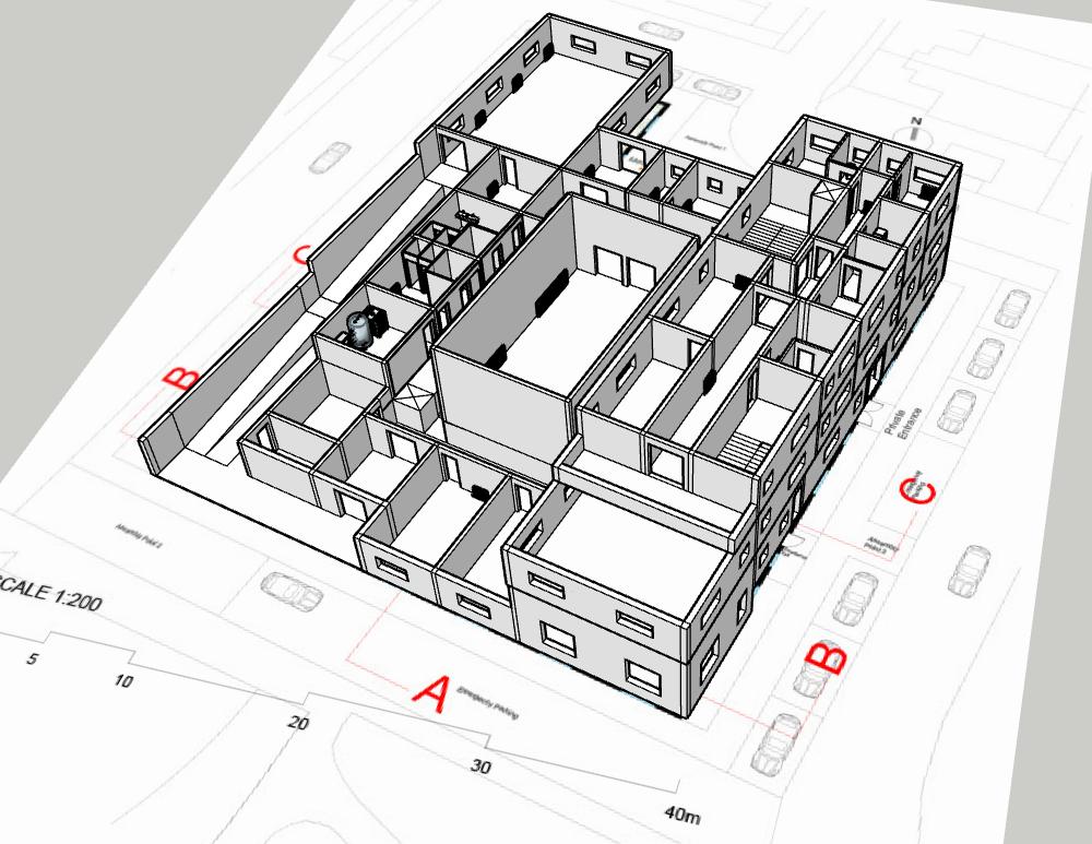
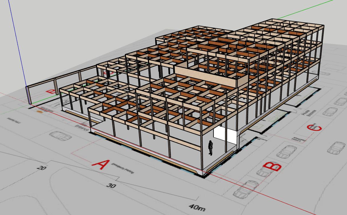
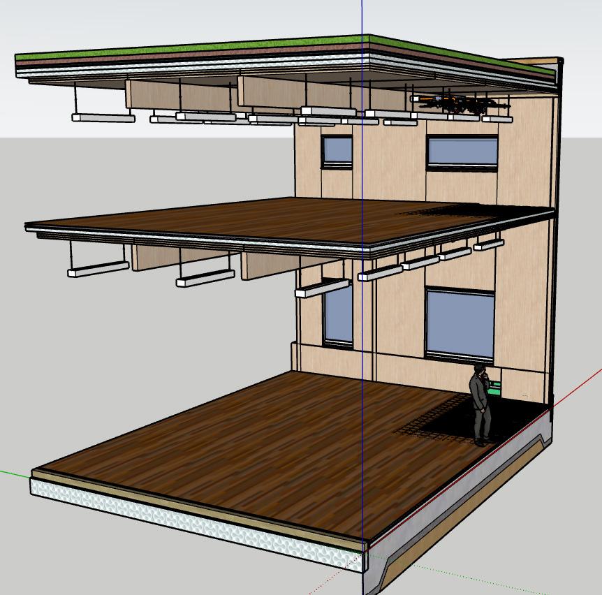
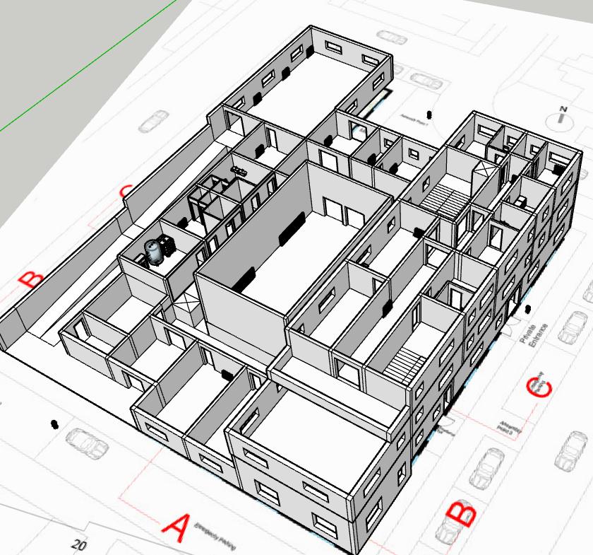
As a community art building with a ground floor of 1345.0625sqm, first floor of 364.8375sqm, and second floor of 313.0875sqm, with a total area of 2022.9875sqm, technically it requires a very strong and stable overall structure.The main structure composed of glulam frames, clt floor slab, and concrete foundation can achieve such a design. The building is mainly composed of the above eight materials, and the selection of building materials is relatively environmentally friendly.
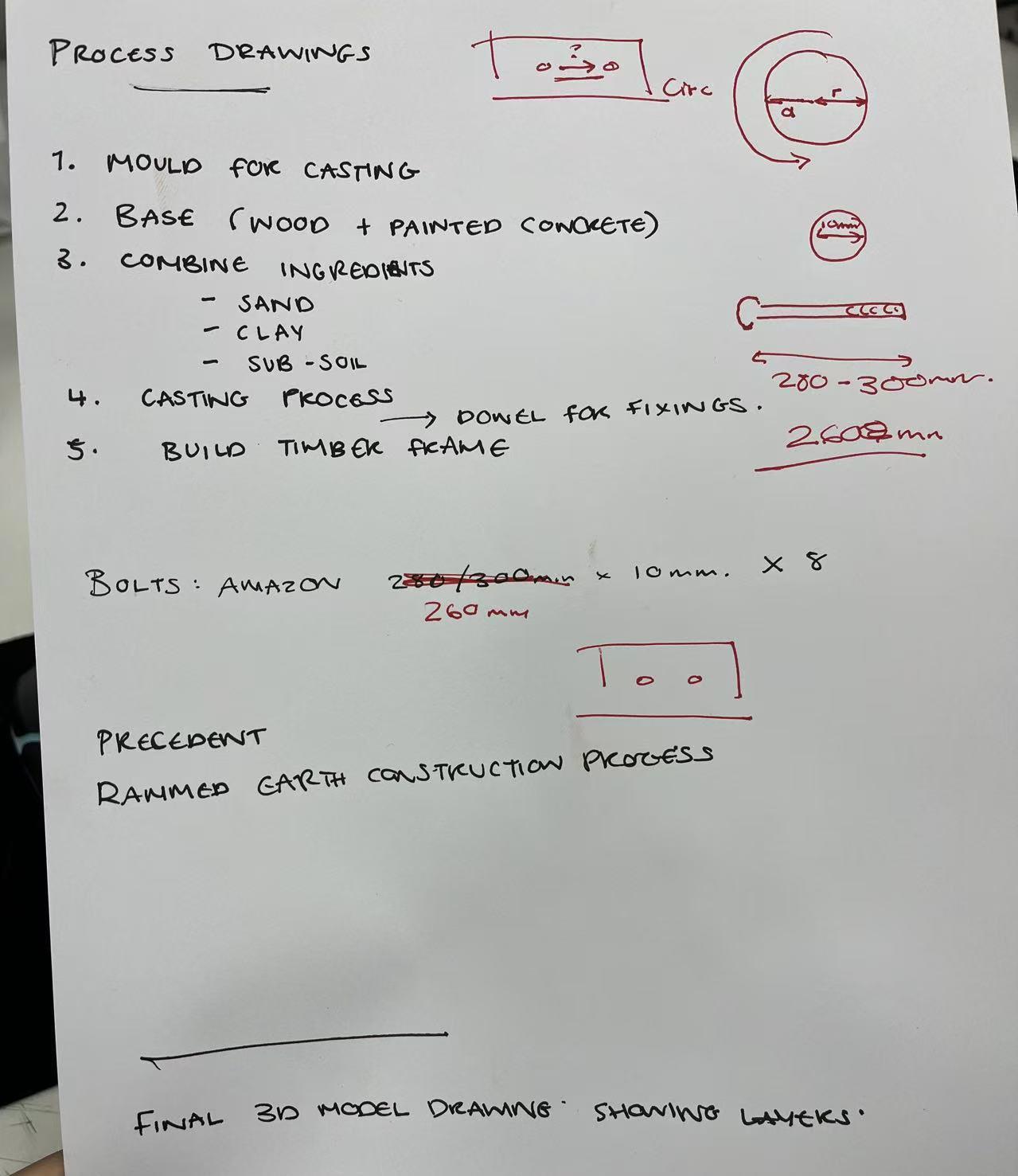
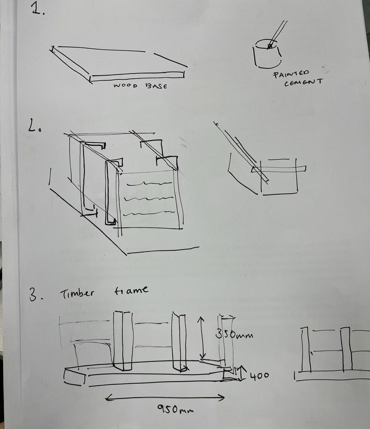
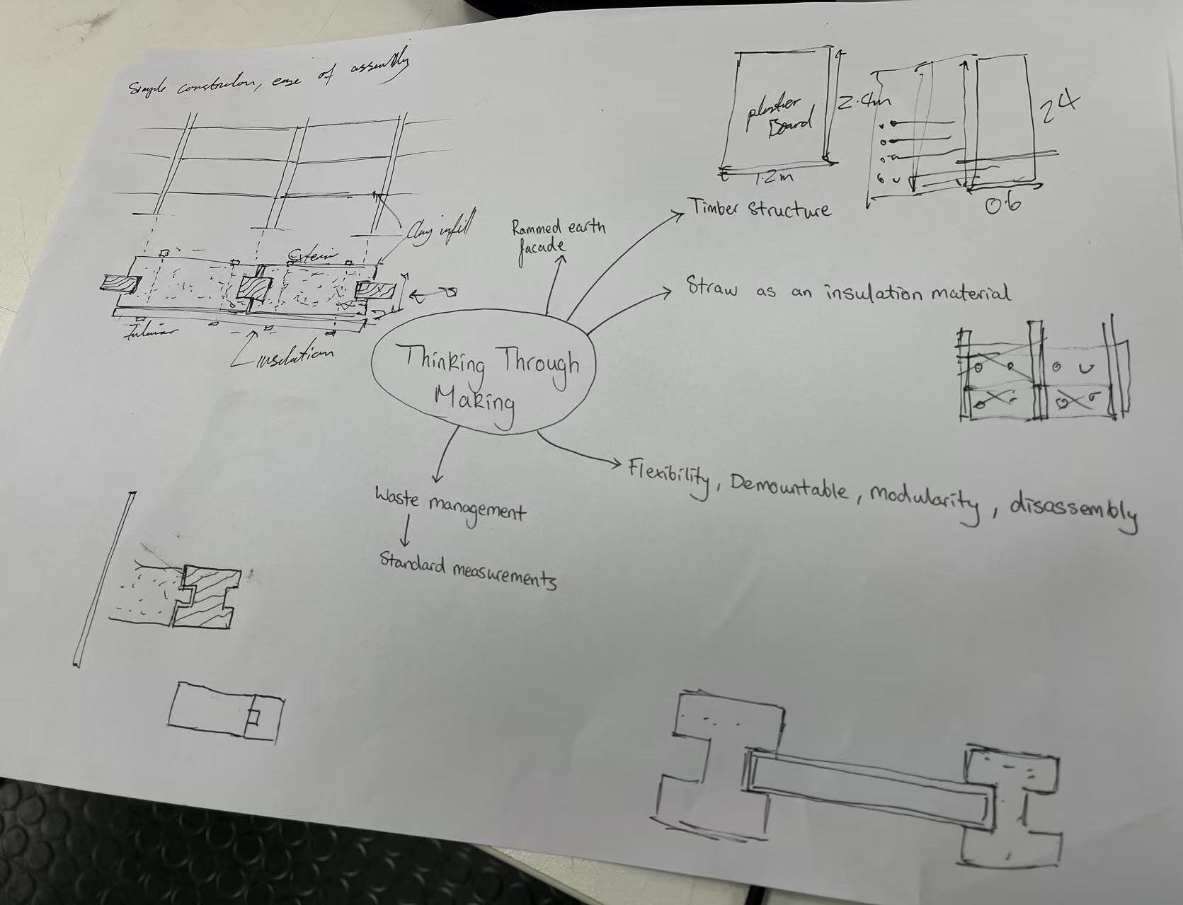
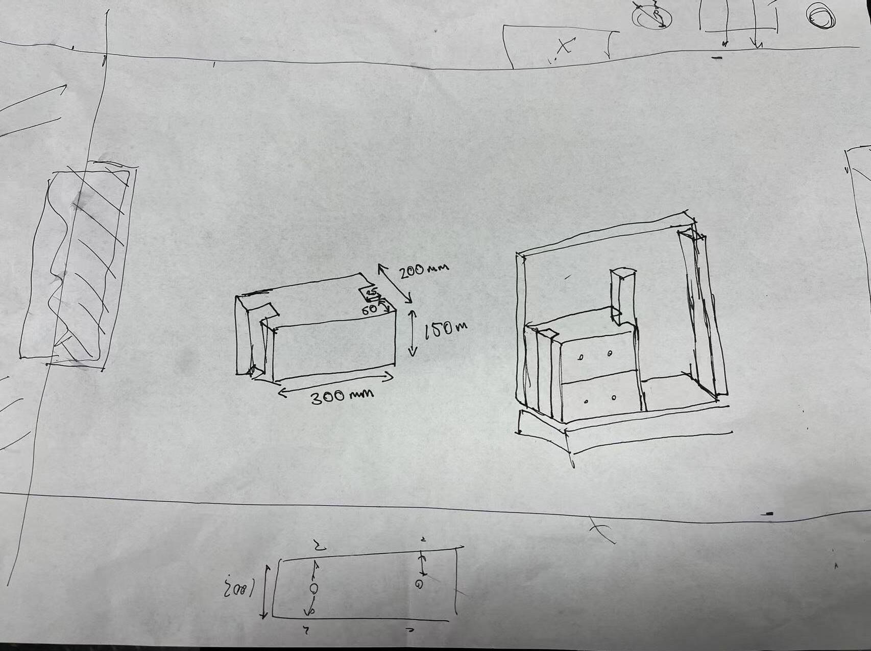
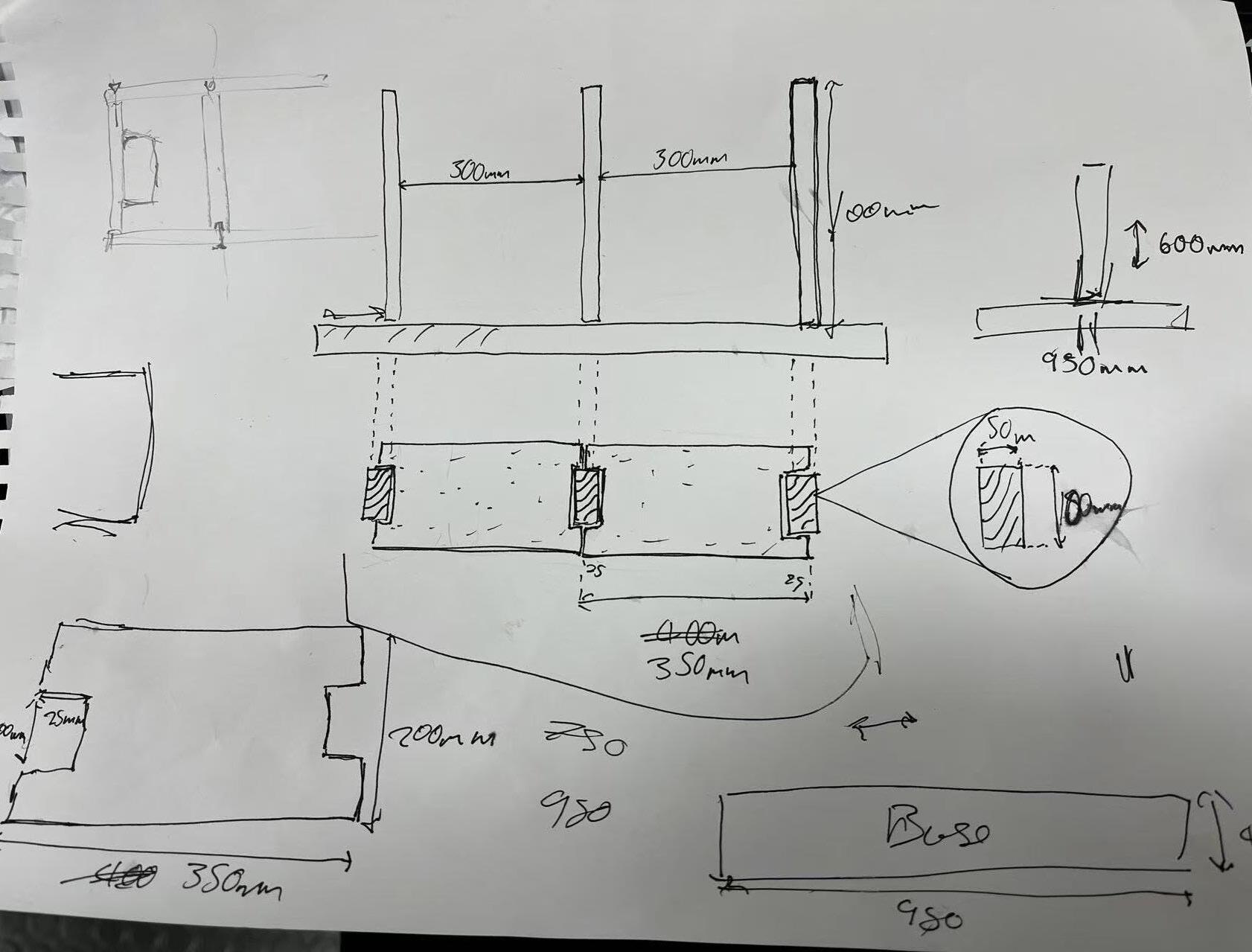
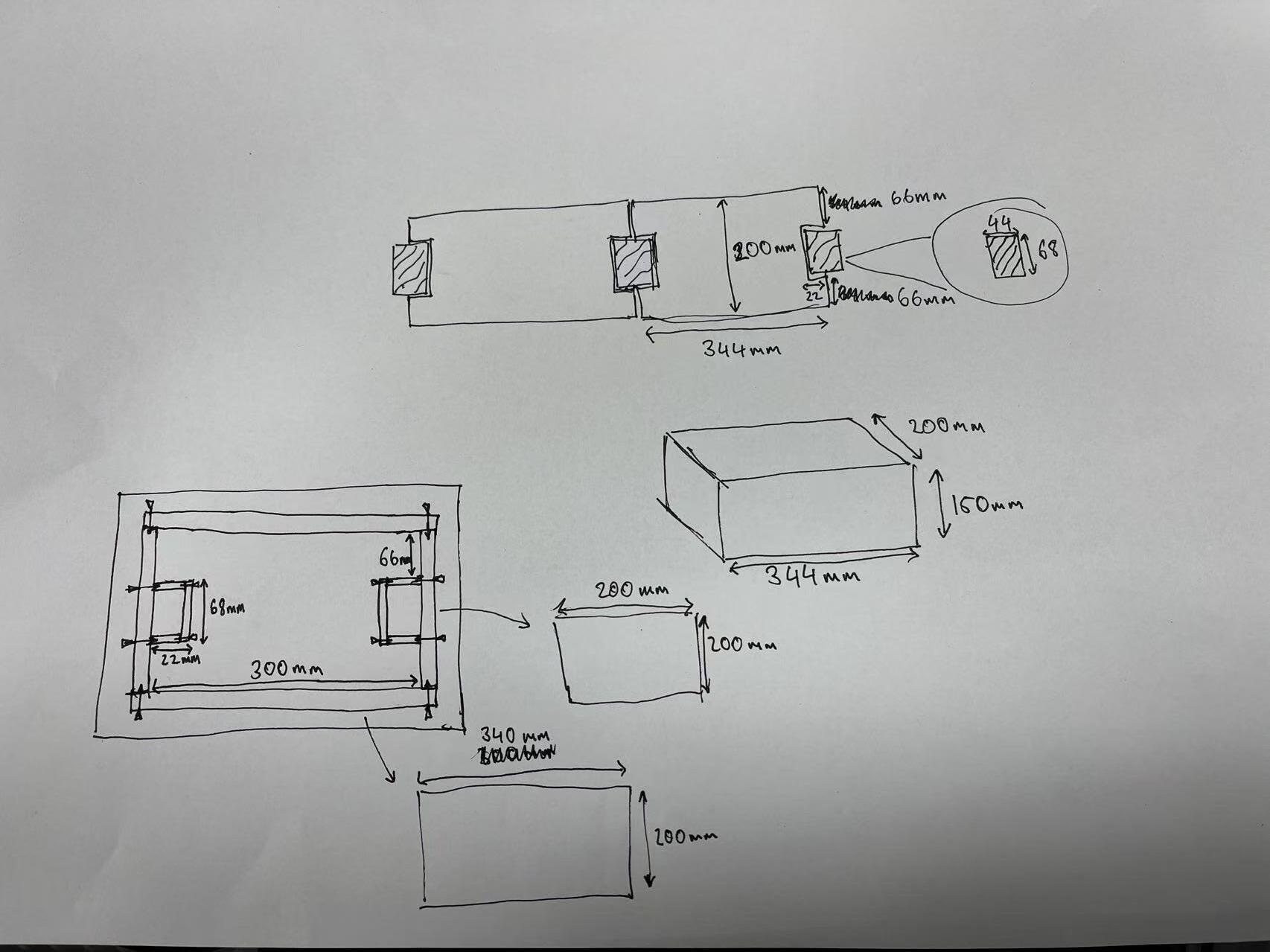
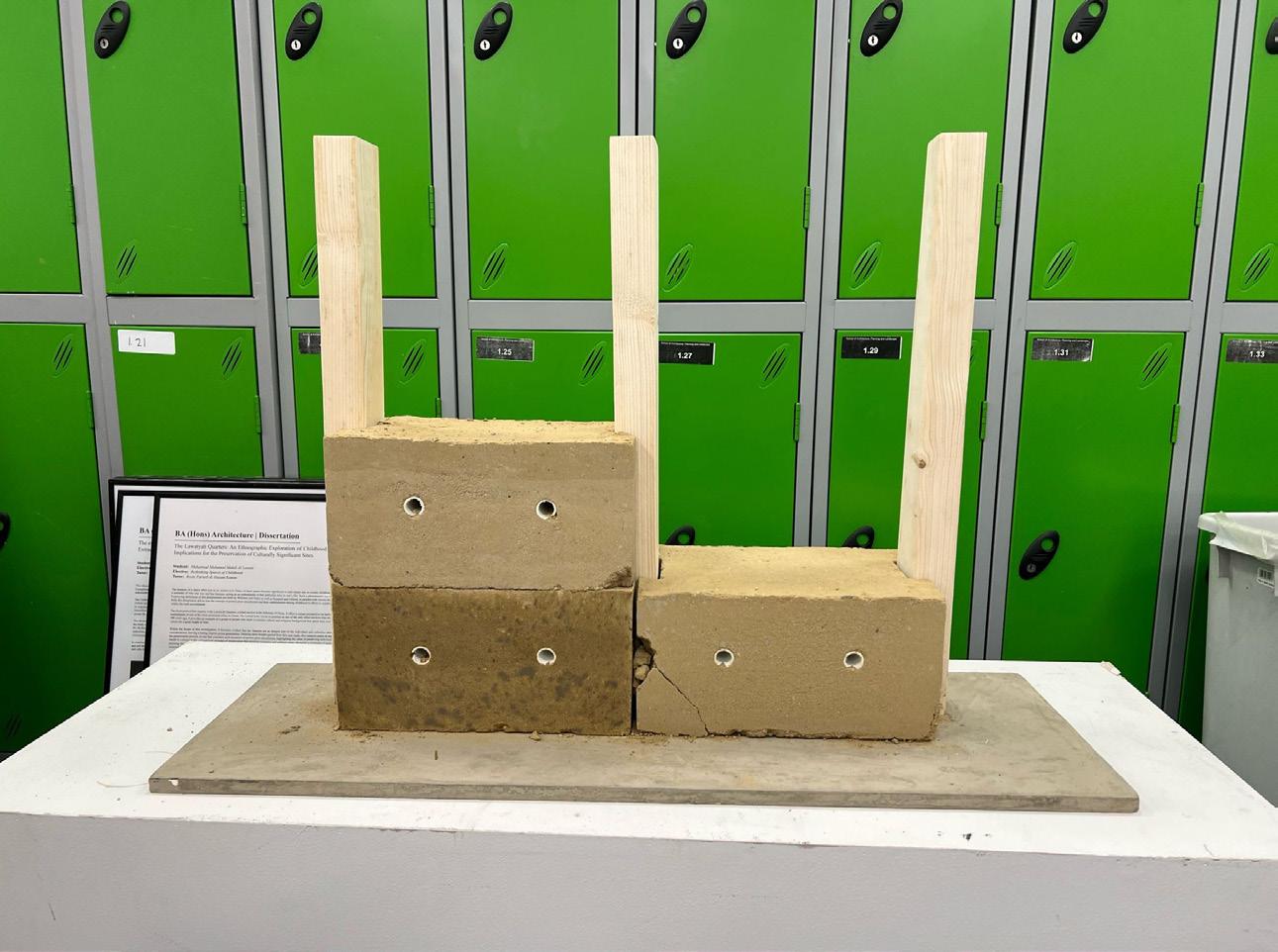
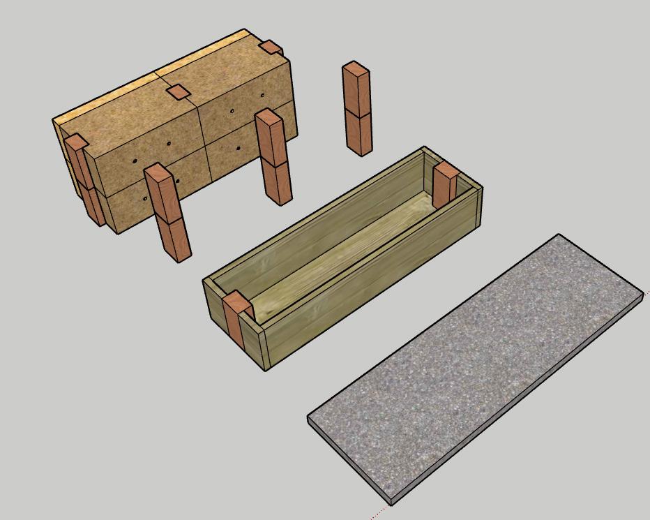
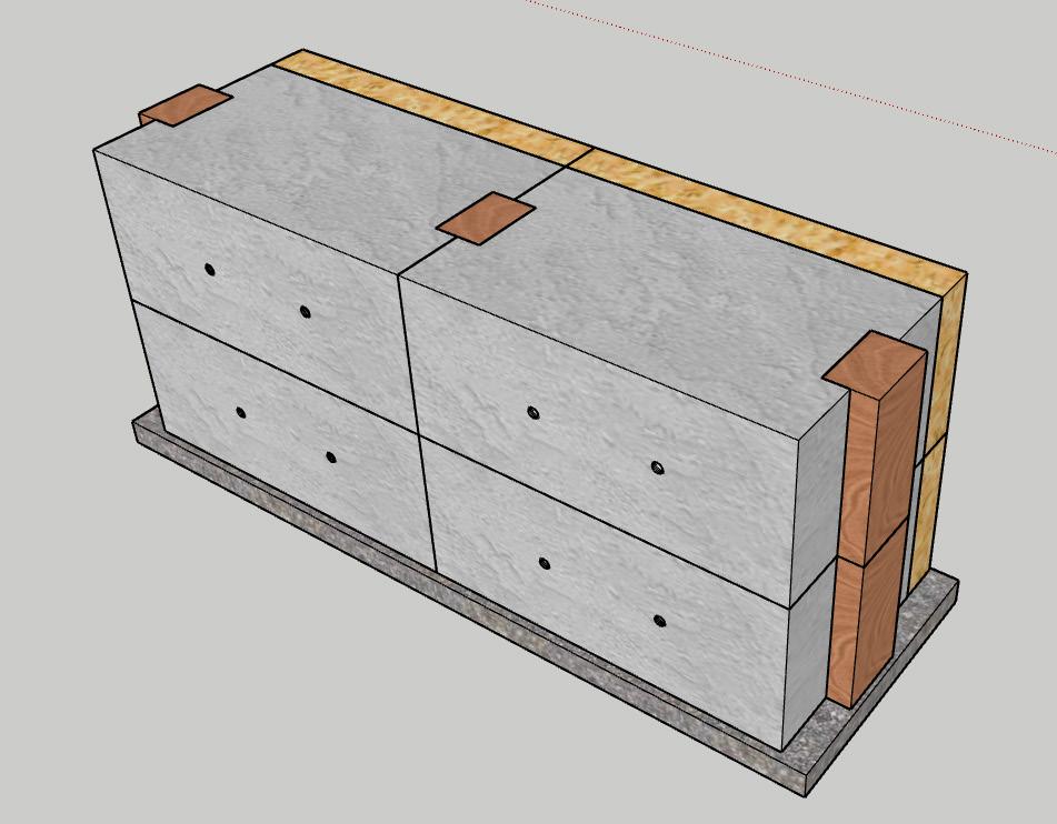
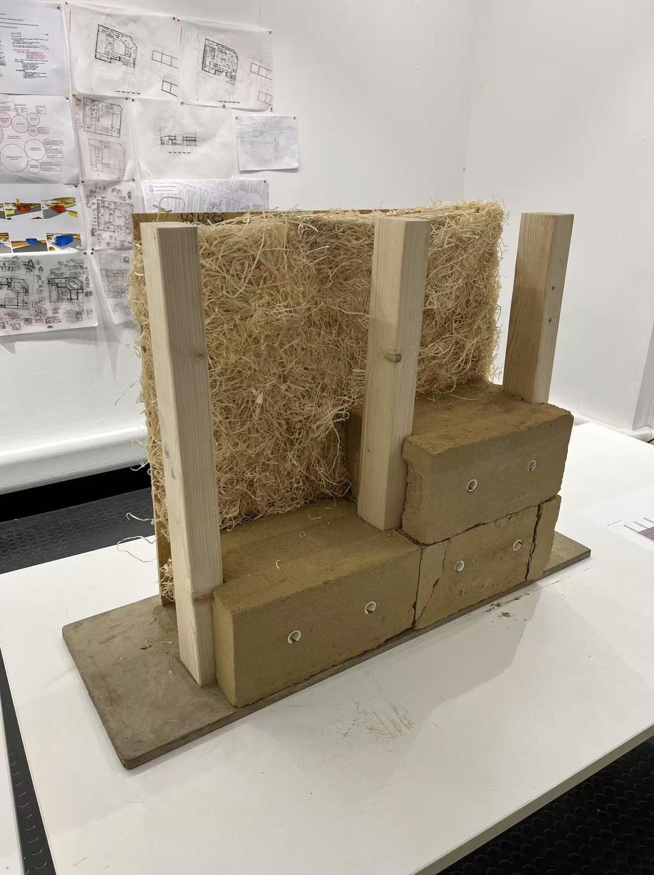
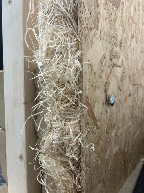
As a sub-group within the Studio 7 Loose Fit, we discussed how to use rammped earth, timber, wood fibre, and concrete slab to make a 1:1 model for modular external wall for a community building we are going to design.
2.1 How have you chosen your topic of research and how is it related to your project?
2.2 How have you undertaken the research?
2.3 What have you learned from undertaking the research?
2.4 How has your research influenced the subsequent development of your building design?
Our group initially explored the use of timber, rammed earth, wood fibre and concrete as primary materials for external wall structure. While rammed earth offers excellent thermal performance and aesthetic qualities, its longterm brittleness limits its structural applications, making it unsuitable for load-bearing walls. As a result, in my individual design, I opted not to incorporate rammed earth. Instead, I adopted glulam frame and CLT floor slabs, concrete foundation as the main structural system—both widely used engineered timber products known for their strength, sustainability, and ease of prefabrication. Additionally, wood fibre insulation is employed throughout the building envelope, including the exterior and interior walls, floors, and ceilings, contributing to both thermal efficiency and environmental performance.
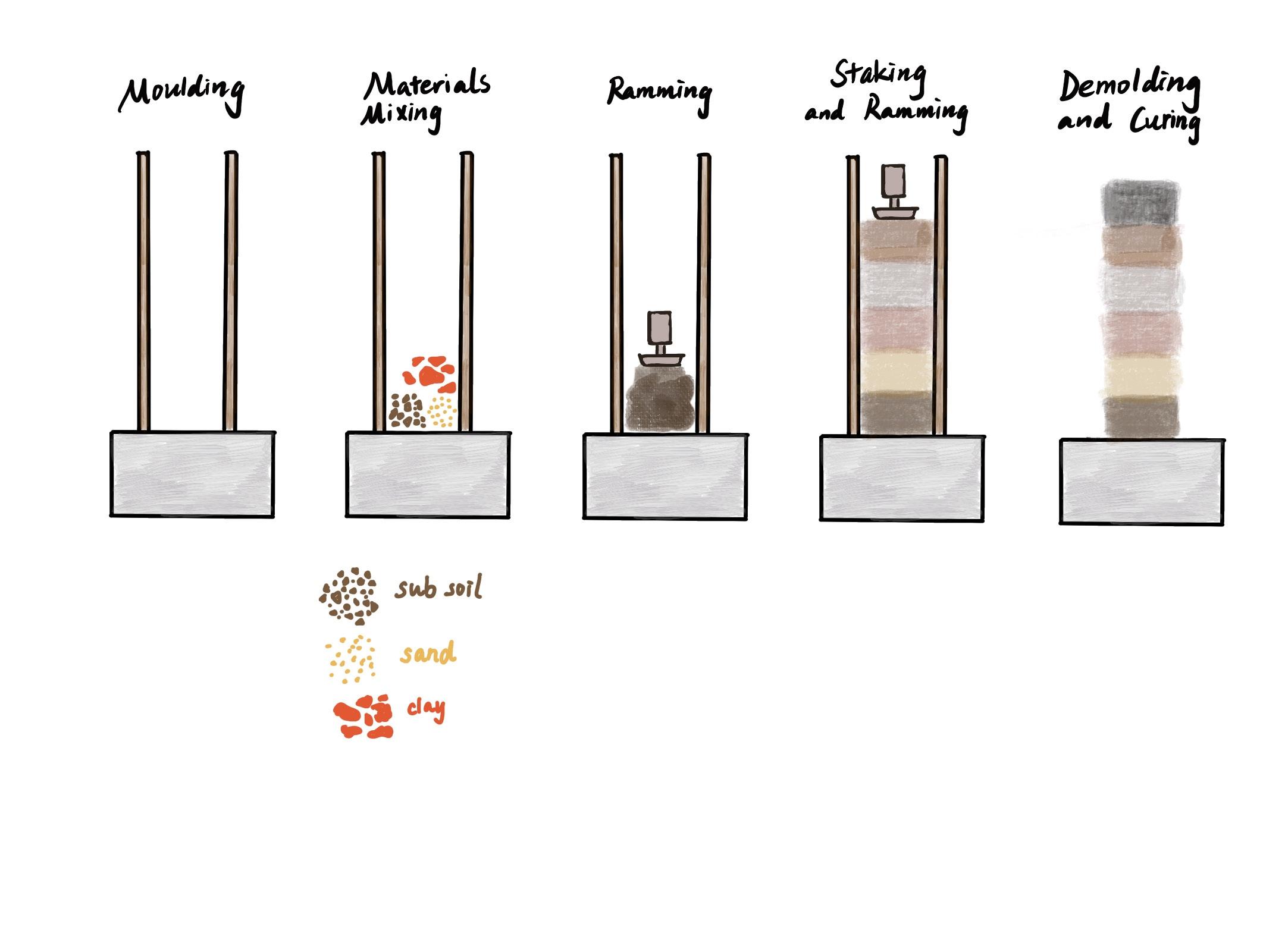
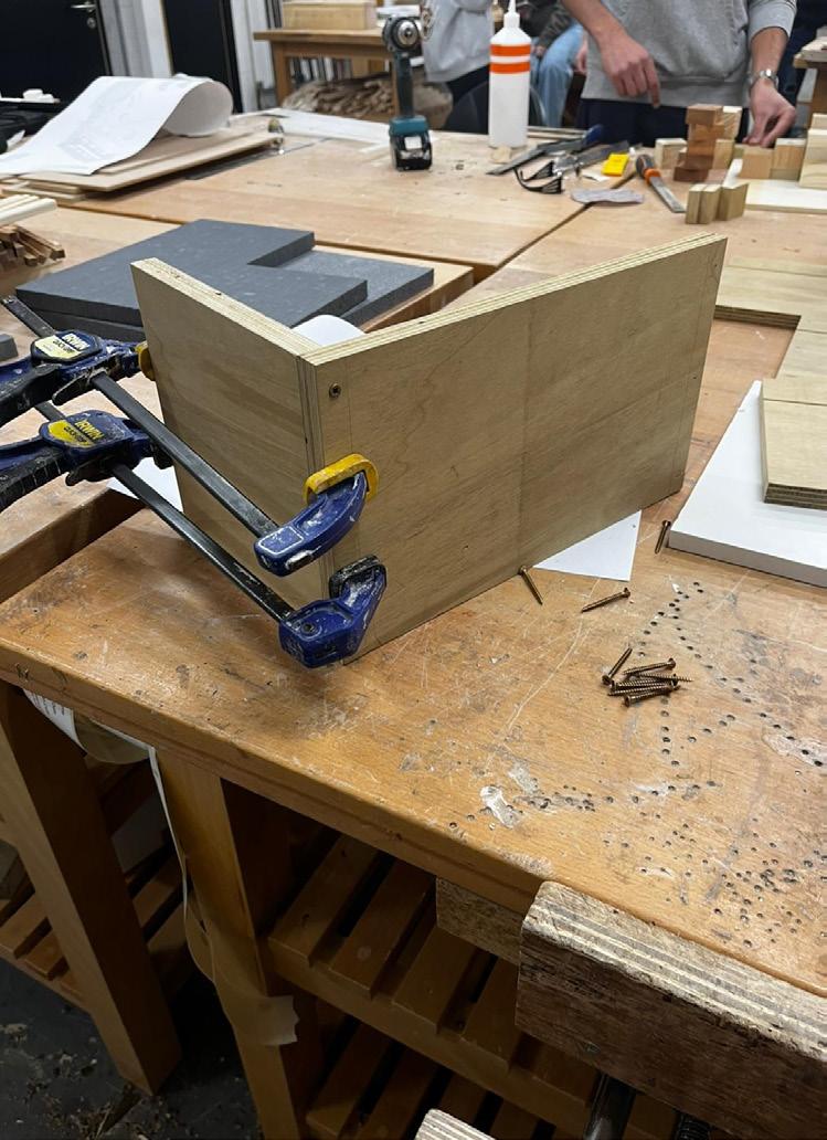
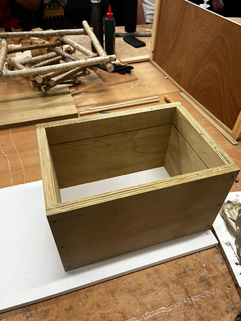
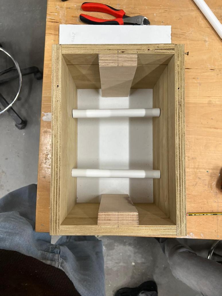
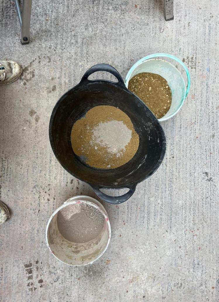
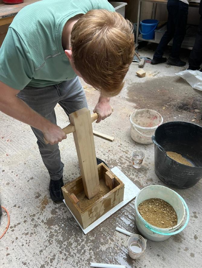
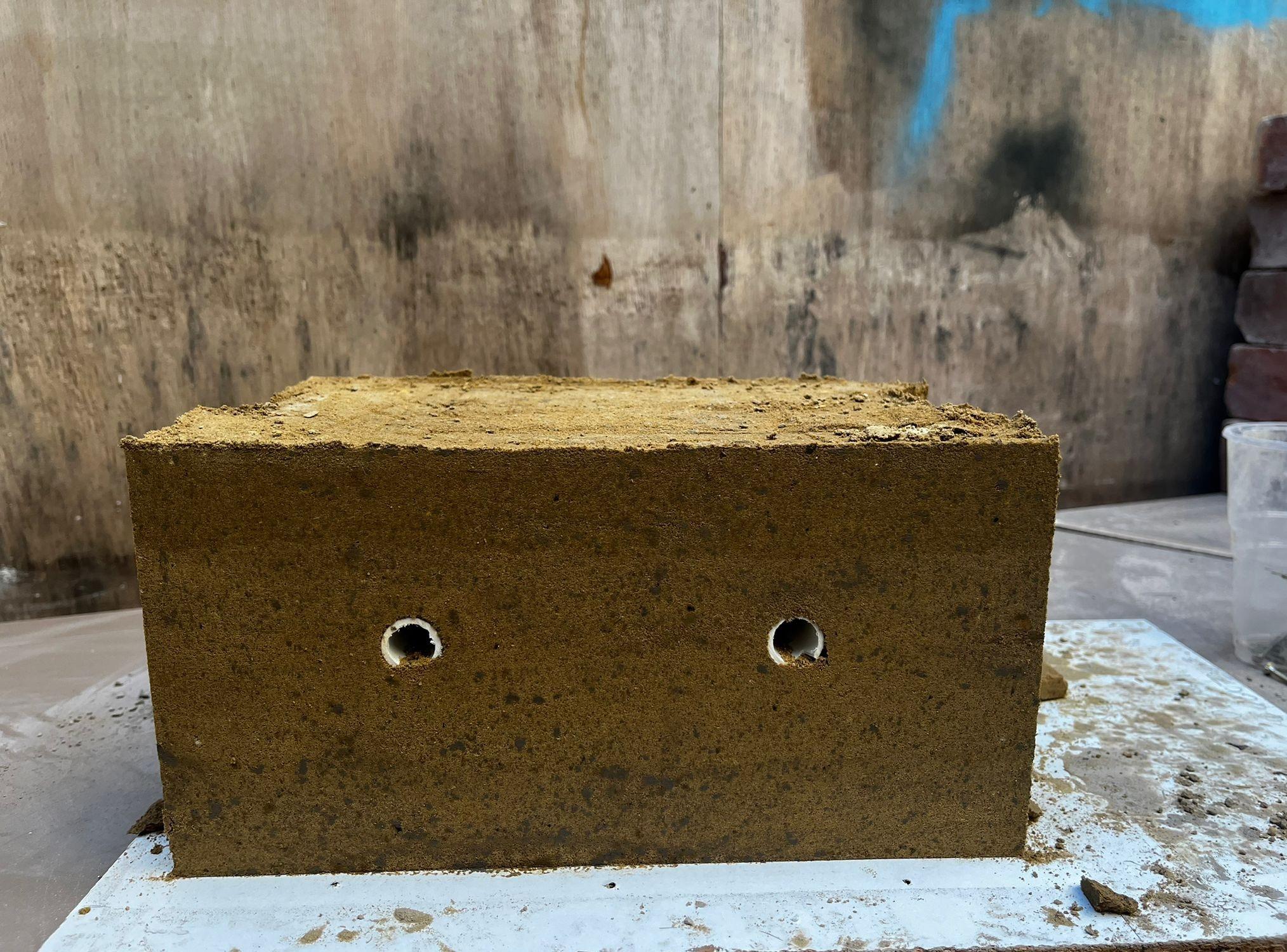
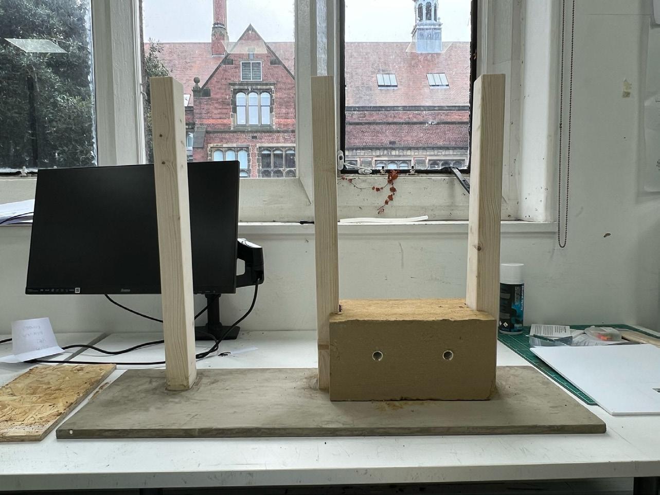
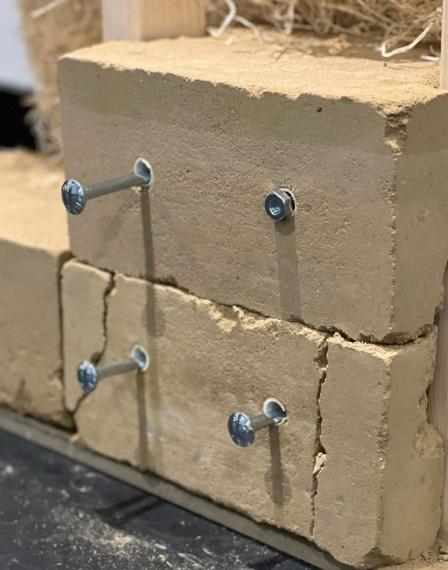
Mold for rammed earth blocks with pipes embeded for future drainage system were made first, then after having the amount of earth-sand-clay propotion tested, ideally 1:5:6 or 1:4:8, materials could be put into the mould to be rammed. When a piece of rammed earth was demolded, it became a very neat squared shape. Eventually, timber, rammed earth and concrete slab were able to be assembled together.
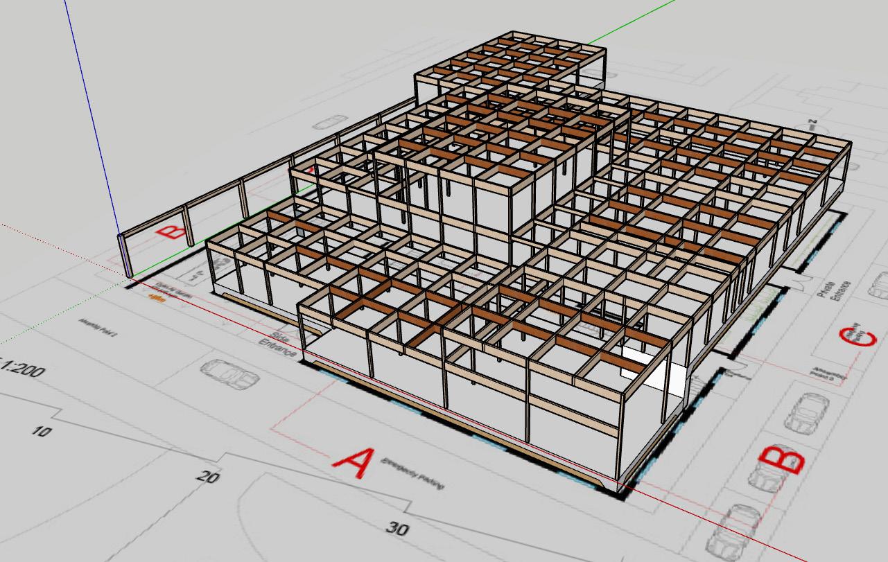
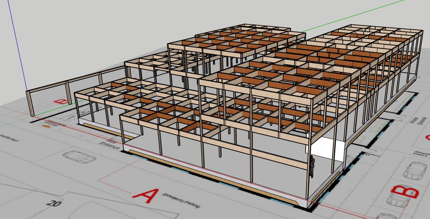
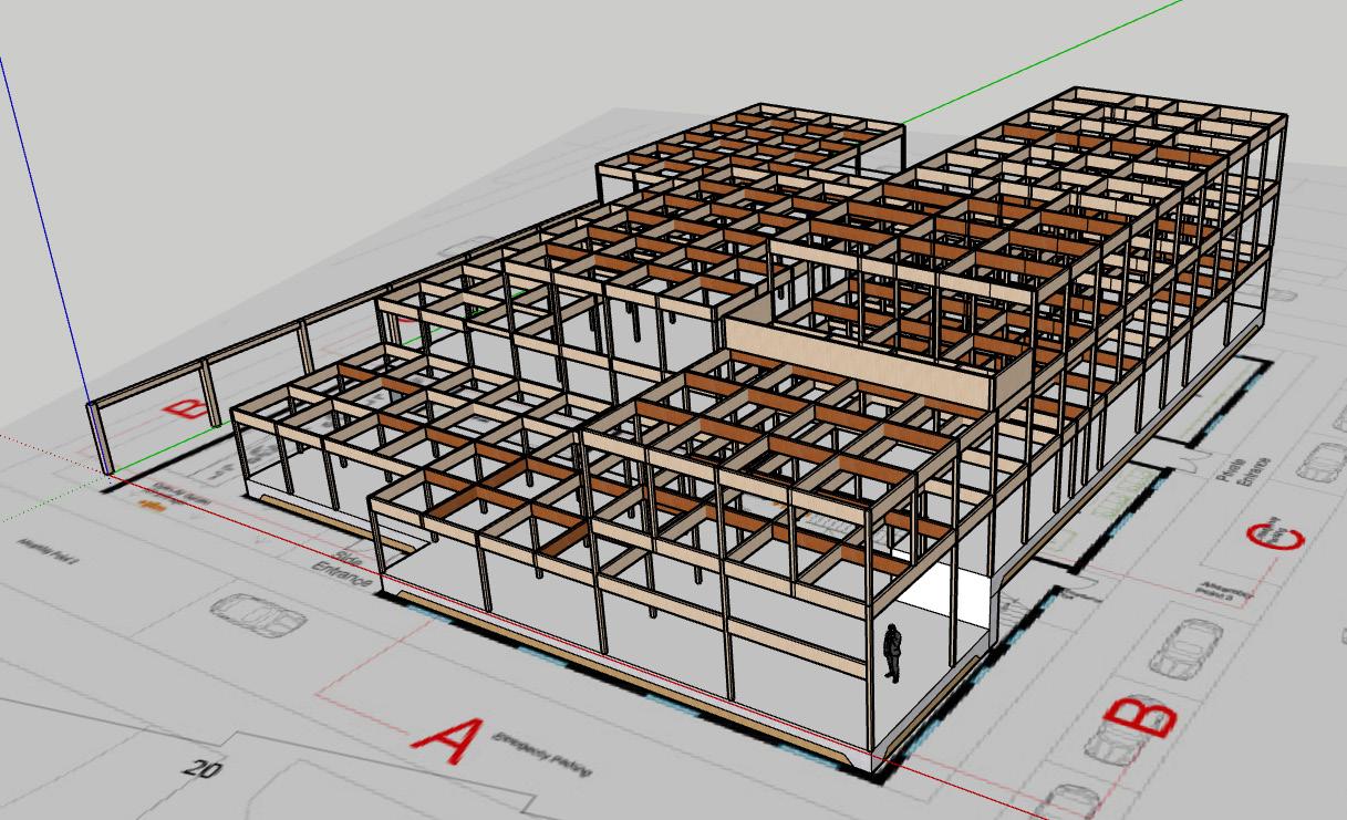
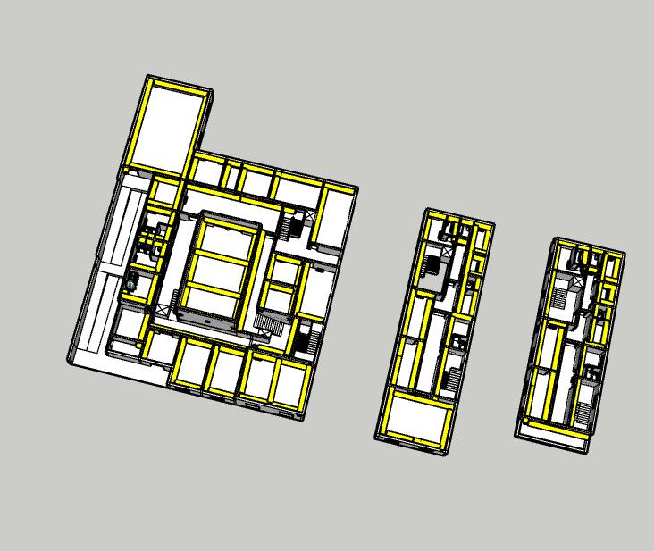
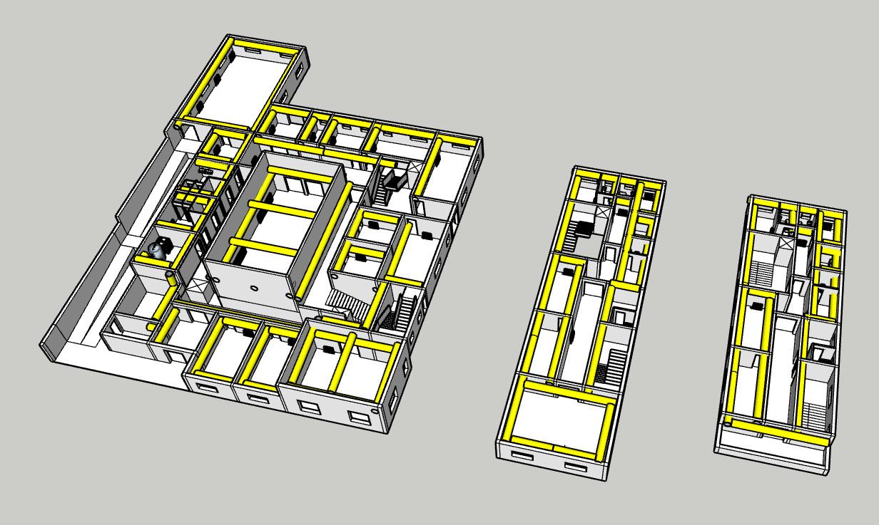
3.1 How are structural loads transferred from roof level to the ground?
Primary Structure:
Concrete Foundation (Grey)
Glulam Columns(Yellow)
Glulam Beams(Yellow)
Secondary Structure:
Small Glulam Transferring Beams (Brown)
Dimensions:
Concrete Slab-800mm thickness
Glulamn Columns-120mm*120mm*3m or 120mm*120mm*5m
Glulam Beams-5000mm*120mm*120mm
Small Glulam Transferring Beams2500mm*120mm*500mm
In such an order from higher to lower spaces: CLT Roof Deck→Second Floor Glulam Transferring Beams→Second Floor Glulam Columns; First Floor CLT Floor Slab→First Floor Glulam Transferring Beams→First Floor Glulam Columns; Ground Floor Glulam Transferring Beams→Ground Floor Glulam Columns→Ground Floor Concrete Slab Foundation.
3.2 How is the building braced against wind?
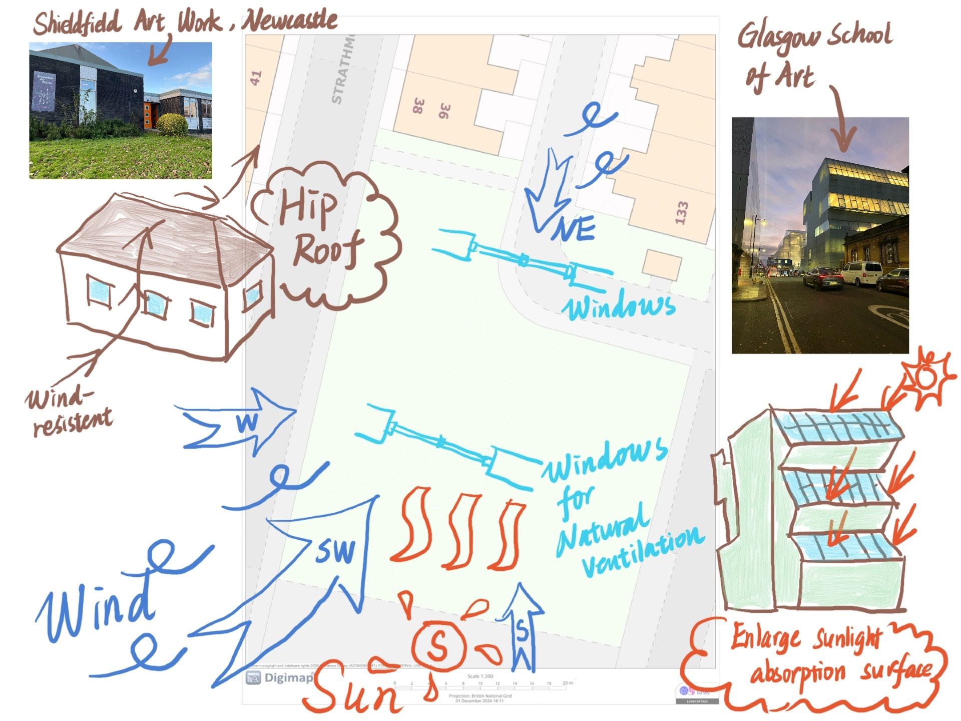
The building responds effectively to prevailing west and southwest winds through strategic orientation and robust detailing. With the more exposed functions set back from the windward side, the glulam frame and CLT floor slabs on intermediate floor provide strong lateral resistance. Concrete used in foundation is one of the most strongest wind-resisting building materials.
The zinc cladding withstands wind suction, while wood fibre insulation can not only allow air to pass through, but also prevent wind pressure from entering the structural layer. Skylights in the event space support natural ventilation ,and skylights and windows in northwest café support cross ventilation, complemented by a mechanical ventilation system that ensures controlled airflow under varying wind conditions.
3.3 How have you chosen an appropriate structure for your building?
For material, I considered the word 'mass timber' first, then decided to use glulam as frame and clt as floor slabs ,then concrete foundation for bearing a great deal of building force, due to their physical characteristics. For the shape of overall structure, I reorganised it in an orderly manner after the approximate shapes of different funcitonal spaces being designed.
3.4 What are your typical structural spans for floor, wall and roof elements, and how have you estimated structural sizes?
This building has a 5m structural grid, sometimes 2.5m, which depends on suitable sizes for different spaces, with External wall (thickness 280mm), internal wall (thickness 234mm), glulam column (thickness 120mm), glulam transferring beam (width 120mm and thickness 500mm), clt floor slab on intermediate floor and clt roof deck (thickness 120mm), concrete foundation (thickness 800mm). I determined the size of different spaces first and then considered the size of structural materals and the grid.
4.1 How does your project preserve, integrate and enhance natural habitats which encourage biodiversity?
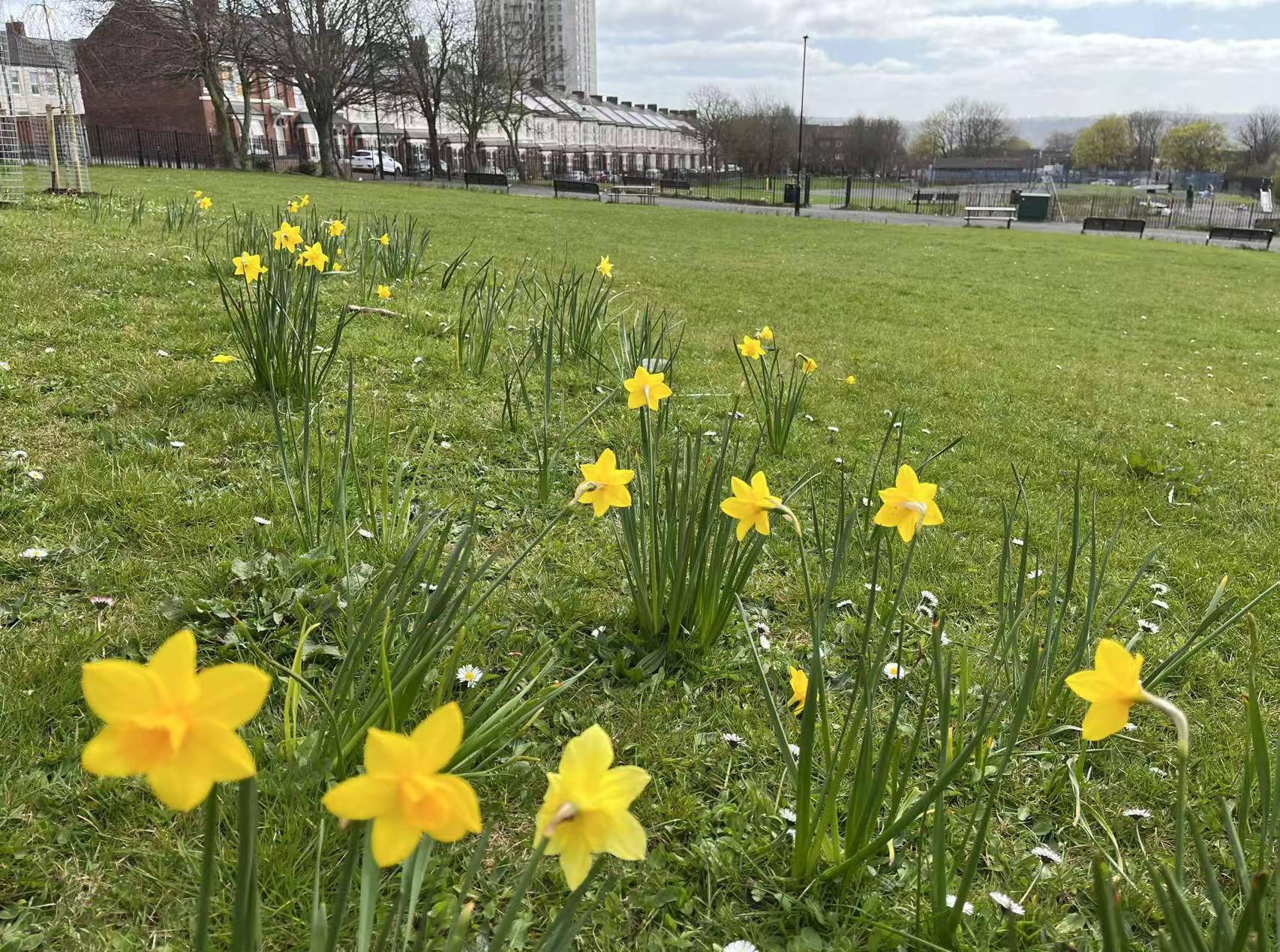
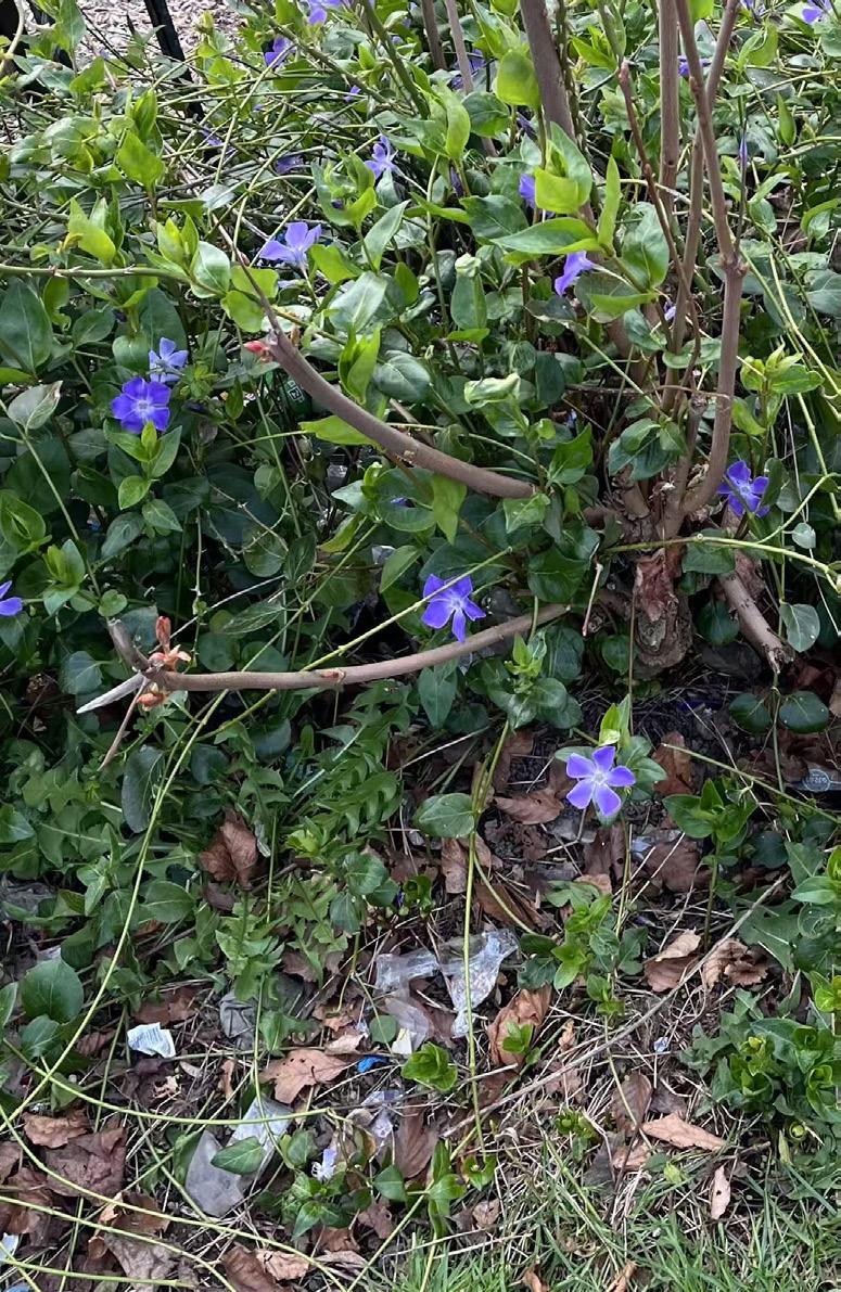
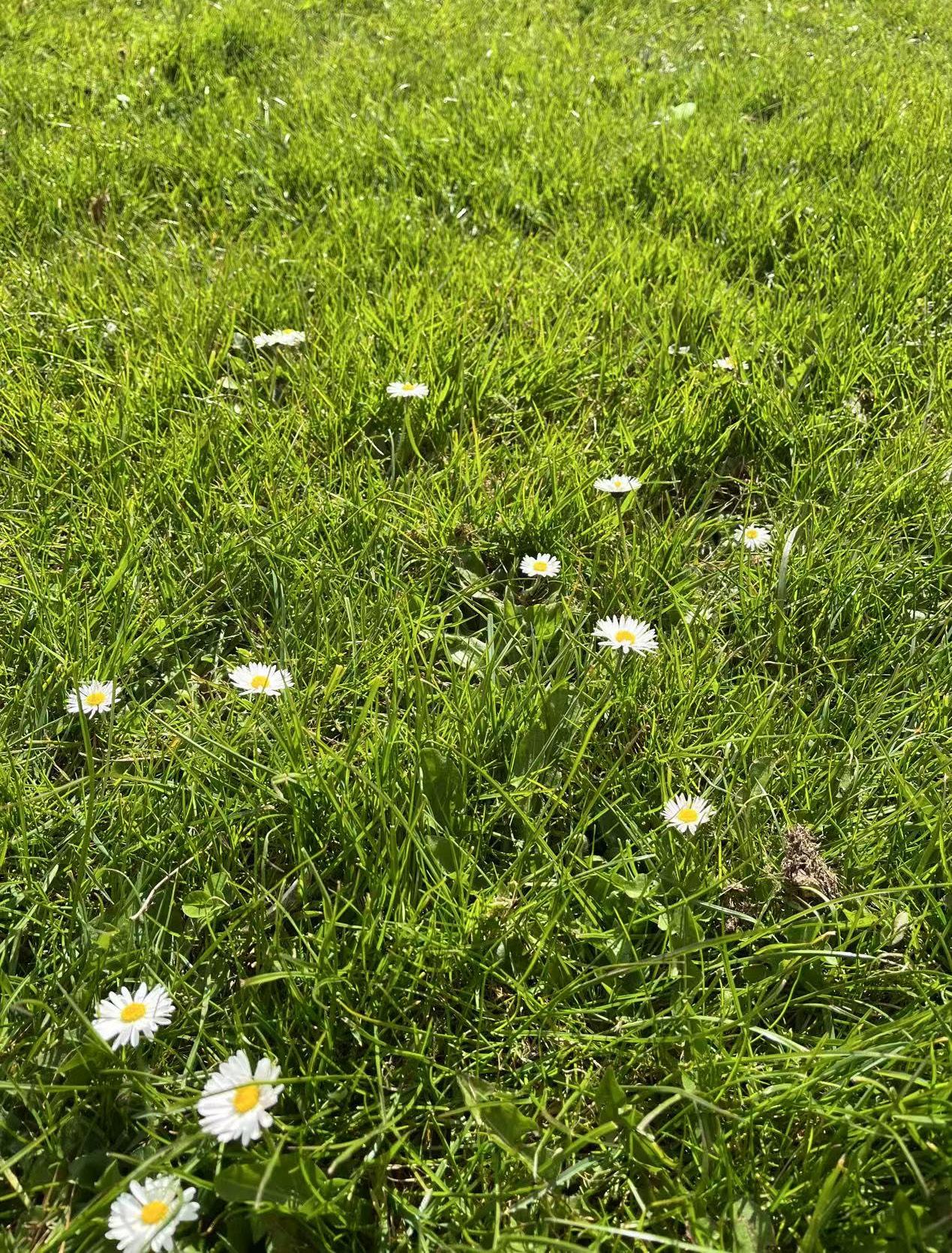
The project is designed to preserve, integrate, and enhance natural habitats that promote biodiversity through a combination of green strategies, including an open-air community garden, a green roof, and a continuous green belt surrounding the building. The open-air community garden serves not only as a shared green space for residents but also as a biodiverse habitat, featuring a rich variety of native and pollinator-friendly plants that attract bees, butterflies, and other beneficial insects. It encourages community engagement and environmental education, fostering a sense of stewardship for nature.
The green roof further contributes by providing a layer of vegetation that supports urban wildlife, including birds and insects, while also reducing the urban heat island effect and improving stormwater retention. It introduces greenery into the vertical plane of the building, increasing the total ecological surface area within the site.
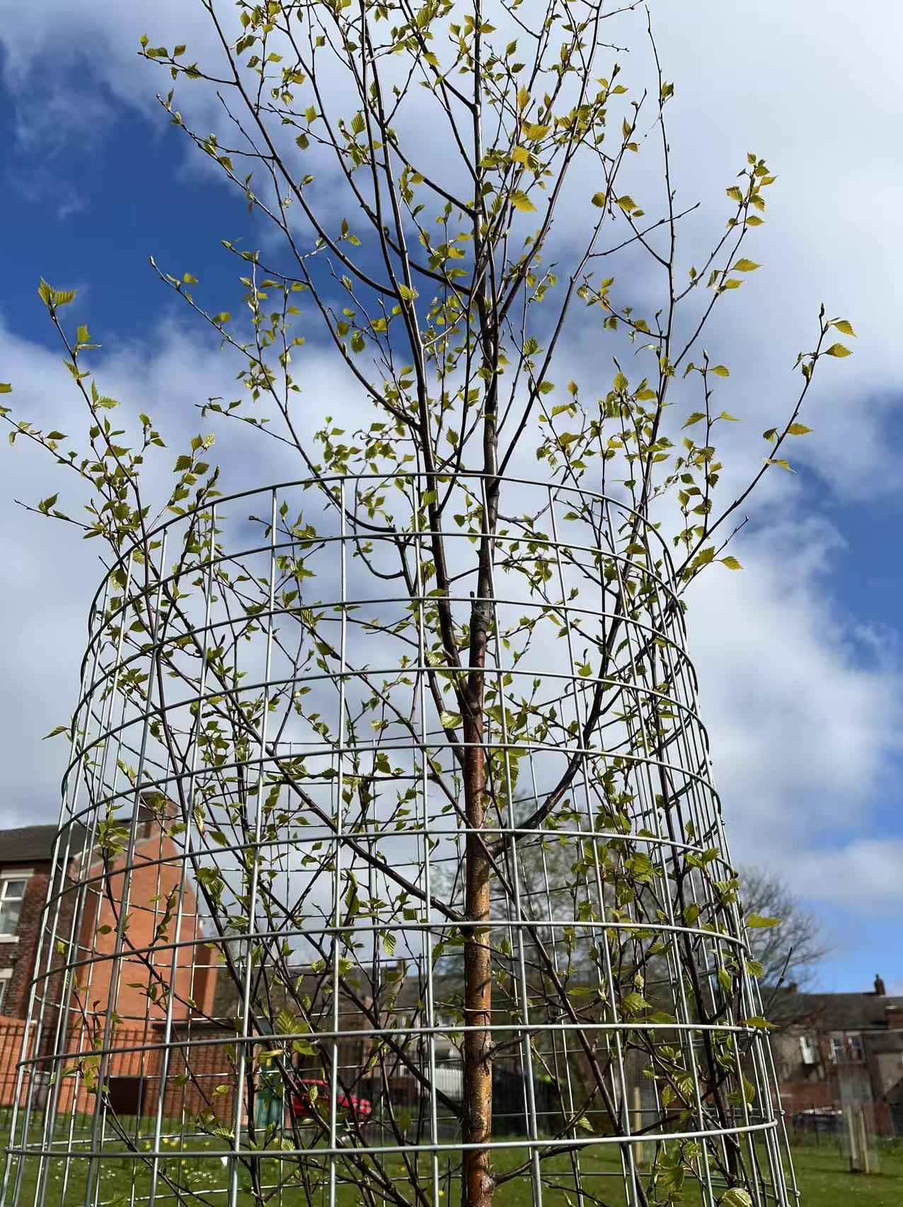
Surrounding the building, a thoughtfully designed green belt with layered planting—including trees, shrubs, and groundcovers—acts as a natural buffer and ecological corridor. This green belt connects with existing nearby green areas, allowing small animals and birds to move safely through the urban environment, enhancing habitat connectivity. Together, these elements create a resilient and multi-functional landscape that supports a wide range of species and strengthens the site's ecological value within the urban context.
4.2 How does your project support access to green infrastructure space for communities?
The project supports community access to green infrastructure through the integration of an open-air community garden, extensive green roofs, and surrounding green belts, all designed to be inclusive, multifunctional, and accessible.
Located at the southwest corner of the site, the community garden acts as a green corridor that connects seamlessly with the existing on-site grassland. It is equipped with accessible ramps and staircases to ensure ease of movement for people of all ages and physical abilities. This garden not only offers a place for relaxation and social interaction but also plays a vital role in local food production—edible plants grown here are supplied directly to the adjacent kitchen and used in the café, creating a direct link between green space and daily community life. This closed-loop system enhances environmental awareness and encourages community participation in sustainable practices.
While green roofs are less directly accessed by the public, they contribute significantly to the overall environmental quality of the community by replacing lost green space and supporting non-human life. These roofs provide important ecological functions such as habitat creation for birds and insects, and contribute to cleaner air and cooler microclimates, indirectly benefiting residents and enhancing their connection to nature.
The green belts surrounding the building offer everyday encounters with nature for residents and passersby. They visually soften the built environment, improve walkability, and provide natural resting areas for birds and small wildlife. By incorporating diverse vegetation and maintaining open access around the site, the project ensures that green space is both physically and visually accessible to the broader community
Through this layered approach, the project fosters strong connections between people and green space, making ecological infrastructure an integral and inclusive part of everyday community life.
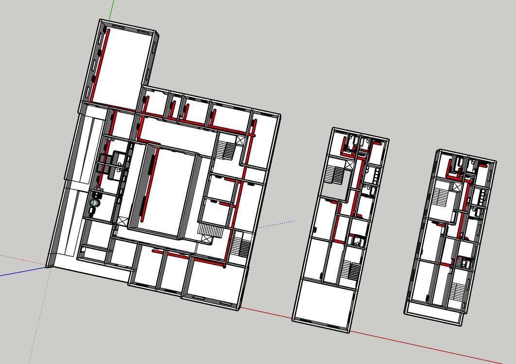
4.3 How does your project utilise water responsibly?
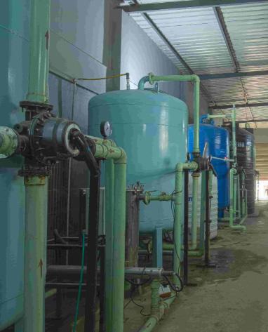
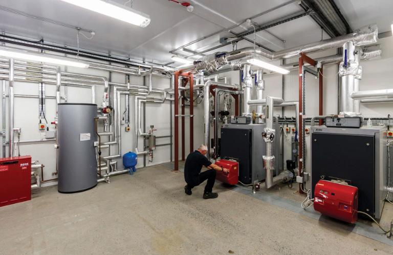
Grey Water Recycling System:
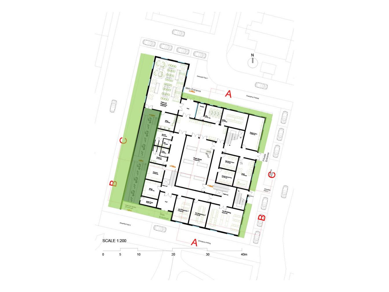
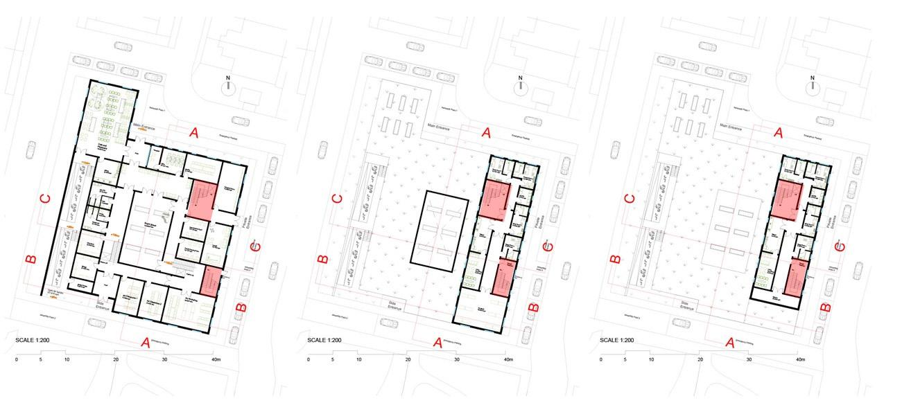
The grey water recycling system in this project is designed to promote water conservation and reduce the environmental impact of building operations by reusing water from domestic sources, excluding kitchen wastewater. In the floor plan, water-consuming spaces are highlighted in different colors: blue represents the kitchen, and grey represents bathrooms, toilets, and laundry areas. The red-marked area on the ground floor is designated as the plant room, where grey water treatment will take place.
Due to the high levels of oil and grease contamination typically found in kitchen wastewater, which require costly and complex purification processes, the recycling of kitchen water is intentionally excluded from the system. Instead, the system focuses on more manageable grey water sources, including bathwater, washbasin water, and laundry water generated on the 1st and 2nd floors.
This grey water is directed downward via gravity-fed piping to the ground floor plant room. Grey water treatment equipment performs multiple stages of purification, including filtration to remove particulates, sedimentation to allow heavier particles to settle, disinfection to eliminate harmful microorganisms, and storage in a dedicated tank. The treated grey water is then reused for non-potable applications such as flushing public toilets and irrigating gardens located adjacent to the plant room.
This system reduces the overall demand for fresh water, lowers operational costs, and supports the project's broader sustainability goals by efficiently managing on-site water resources.
4.4 How does your project minimise energy in-use?
Form Factor
=Envelope Area/ Volume
=2404.78 m²/6076.99 m³
=0.395545146
The envelope area of my building includes all the covering area of building, both top and side areas of spaces, and additionally the external surface of my second floor balcony and the open-air flooring of it.
The volume of my building includes every size of the massing in my building.
The design complies with the requirements of Approved Document L (2021 edition) in terms of insulation values, air permeability, and energy efficiency. A compact building form (form factor 0.39) reduces the overall envelope area and therefore helps to minimise heat loss, making it easier to achieve compliance with fabric energy efficiency standards.
Formula for U-Value Calculation:
U=1/ R=1/(d/λ)
A compact form factor reduces the overall external envelope area relative to the internal volume, which in turn lowers heat loss. This allows the building to meet thermal performance targets with less demanding U-values. Conversely, more complex building forms require higher-performing (lower) U-values to compensate for the increased surface area and associated heat loss.(Approved Document Part L)
Knowing the thermal conductivity (λ)of each layer of material and thickness of each layer of material (d), the thermal resistance (R) could be calculated. By summing up all the thermal resistance of all the layers of the area to get the total thermal resistance, u-value could finally be calculated.
External Wall U-Value Calculation:
R = m²K/W
U=1/R= W/m²K
0.168600799W/m²K is less than 0.26 W/m²K (Approved Document Part L)
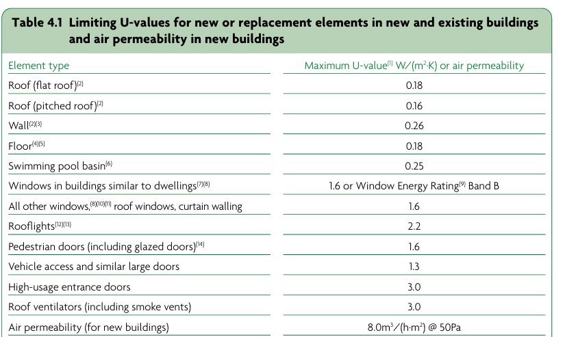
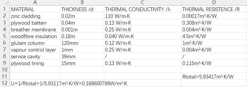
The external wall build-up achieves a U-value of 0.16 W/m²·K, exceeding the minimum requirements set out in (Approved Document Part L)
The construction comprises glulam frames, clt floor slabs and concrete foundation structure,with woodfibre insulation providing excellent thermal performance while maintaining breathability and moisture regulation. A plywood internal lining contributes to the robustness of the wall system and supports low-VOC finishes. This fabric-first approach enhances occupant comfort and reduces operational energy demand, while also ensuring good levels of airtightness when paired with appropriate detailing and membranes.
Zinc Cladding 1mm
Breather Membrane 1mm Air Gap 40mm
Woodfibre Insulation 60mm
Woodfibre Insulation 120mm
Vapour Control Layer 1mm
Service Cavity 39mm
Plywood Lining 15mm
The building has a form factor of 0.39, which is relatively compact. This results in a reduced external surface area in relation to the internal volume, lowering overall heat loss. Consequently, the external wall achieves a U-value of 0.16 W/m²K, which is well below the limiting values set by Approved Document L (0.26 W/m²K), demonstrating that the thermal envelope performs effectively. The good balance between a low form factor and low U-values ensures that energy efficiency targets can be comfortably met. (Approved Document Part L)With a compact form factor of 0.39 and highperforming external walls (U-value 0.16 W/m²K), the building envelope achieves excellent thermal efficiency and easily complies with current regulatory standards.
4.5 How does your project minimise 'upfront' embodied carbon?What opportunities are there for re-using materials in your project? What opportunities are there for using ‘carbon-negative’ materials? How might you reduce the carbon cost of transporting materials to site?
This project has been carefully developed to minimise upfront embodied carbon through both a fabric-first approach and the intentional use of renewable, durable, and low-carbon materials. The external wall construction features a zinc cladding outer layer fixed onto plywood battens over a breather membrane, followed by a generous thickness of woodfibre insulation, a vapour control layer (VCL), and an internal structural framework of glulam columns, all finished internally with plywood lining. This build-up combines robustness, material efficiency, and thermal performance. Zinc, while a higher-carbon material per kg, is used only as a thin, durable weathering skin, with a service life of over 60 years and the potential for full recyclability. Meanwhile, the predominant use of bio-based materials — such as woodfibre insulation, glulam, and plywood — significantly offsets carbon impacts, acting as long-term carbon stores within the fabric of the building.
The foundation system is a concrete slab, selected for its structural and moisture protection requirements. However, its use has been limited to where strictly necessary, and the design is being optimised to minimise its thickness and overall volume. Above the slab, the floor build-up includes a DPM (damp proof membrane), a screed layer for load distribution and thermal mass, and a thick layer of woodfibre insulation to reduce heat loss and improve floor comfort — continuing the emphasis on bio-based materials wherever feasible.
The intermediate floor structure is made from cross-laminated timber (CLT) floor slabs, providing both structural integrity and thermal performance with a much lower embodied carbon footprint compared to traditional concrete or steel floor systems. These are topped with a screed to improve acoustic separation and thermal buffering, and finished with plywood flooring, maintaining a consistent palette of renewable materials throughout the interior.
High-performance double-glazed windows ensure excellent energy efficiency and daylighting, while architectural detailing has been carefully considered to support longevity and reduce thermal bridging. Window surrounds include HPL trim panels, fibre cement board jambs, and external brise soleil shading devices constructed from timber and aluminium. This mixed-material approach balances durability with carbon impact: timber provides warmth and renewable content, while aluminium components are minimised and specified for long service life and recyclability
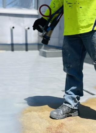
The roof build-up includes a green roof system with an integrated double-layered XPS rigid insulation below the waterproofing membrane. Above this, the roof incorporates a roof barrier membrane, protection fleece, drainage layer, and a growing substrate that supports low-maintenance planting. This system not only improves the building’s biodiversity footprint but also offers rainwater attenuation, thermal buffering, and extended roof lifespan, all contributing to long-term operational efficiency and resilience.
Throughout the design, carbon-negative materials — including CLT, glulam, woodfibre insulation, and plywood — have been prioritised, as they sequester atmospheric carbon during their growth and continue to store it throughout their lifespan. These bio-based materials form the bulk of the thermal envelope and structure, demonstrating a clear commitment to reducing both upfront and long-term embodied carbon.
In terms of material re-use, the project is exploring options for incorporating reclaimed timber, particularly in internal joinery, shelving, or feature wall elements. Plywood offcuts and unused CLT segments from the prefabrication process are also being assessed for potential reuse within secondary construction or furniture. This strategy not only supports circular construction principles but also reduces site waste and demand for original materials.
Finally, to address the carbon cost of material transportation, key construction materials — including woodfibre insulation, timber, and CLT elements — are being sourced from local or regional suppliers where possible. The use of off-site prefabrication for CLT floor slabs and glulam structural elements greatly reduces on-site assembly time, limits waste, and lowers the number of site deliveries. Combined with smart logistics planning and bulk delivery coordination, this helps to further minimise transportation emissions during the construction phase.
Overall, the material and construction strategy is grounded in passive performance, resource efficiency, and long-term environmental responsibility — reducing both the embodied carbon footprint and the operational impact of the building over its lifetime.
4.6 How is your building heated and/or cooled?
The concrete slab absorbs heat during summer days and releases it at night to stabilise indoor temperatures. Sunlight provides natural warmth on both summer and winter days. In summer, air conditioning runs day and night when needed, with windows opened for ventilation only on cooler days and nights. Brise soleil shading blocks high-angle summer sun to reduce heat gain. In winter, windows stay closed and heating is used to maintain comfort. This combination ensures efficient temperature control year-round.
During summer days, the building relies on mechanical cooling through air conditioning with windows closed, while brise soleil shading devices minimize solar heat gain and heat is absorbed into the concrete foundation.
During summer nights,cool air flushes out stored heat, preparing the building for the next day.The stored heat in the concrete is gradually released as the building is naturally ventilated.
During winter days, the building maintains warmth by keeping windows closed and using heating systems, while solar gains and internal heat contribute to maintaining temperature and minimizing heat loss.
During winter nights, heating compensates for heat loss as ventilation is minimized to retain warmth and maintain comfortable indoor temperatures.
*Original size of drawing attached
To reduce the risk of overheating during summer, the building adopts a combination of passive and active strategies.
The external walls are clad with light-coloured (light yellow) zinc panels, which provide higher solar reflectance than traditional dark-coloured claddings, thereby minimizing solar heat gain.
Behind the cladding, wood fibre insulation further limits thermal transmission into the interior.
The roof construction incorporates layers of wood fibre insulation, topped with a green roof that enhances thermal resistance and offers evaporative cooling.
Windows are fitted with brise soleil shading devices to block direct sunlight while allowing natural daylight, effectively reducing heat gain through glazing.
A mix of natural and mechanical ventilation ensures good air circulation throughout the building, while key communal areas such as the ground floor café and double-height event space feature skylights to encourage cross ventilation and maximize daylight. Additionally, the concrete ground floor provides high thermal mass, absorbing excess heat during the day and gradually releasing it at night to stabilize indoor temperatures.
These measures work synergistically to enhance summer comfort and reduce dependence on mechanical cooling.
Fresh air is delivered through multiple systems to ensure good indoor air quality year-round. The event space features skylights that can be opened during cool summer days and nights to provide natural ventilation. Additionally, a mechanical ventilation with heat recovery (MVHR) system located in the ground floor plant room operates continuously throughout the year, efficiently exchanging indoor and outdoor air while recovering heat to maintain energy efficiency. Skylights
The MVHR system operates continuously to supply fresh, filtered air while recovering heat to maintain
The MVHR system continues to run, ensuring fresh air circulation without heat loss during cold winter nights.
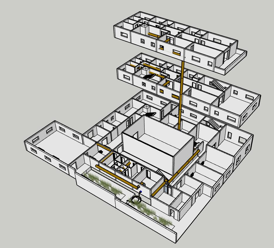
Axonometric Picture
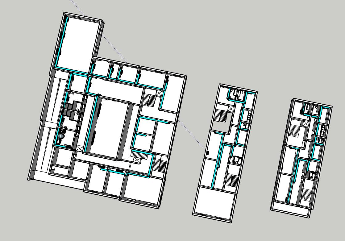
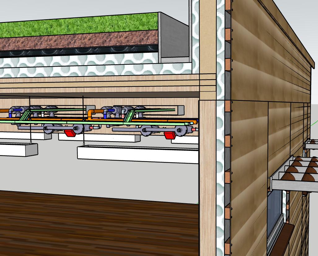
4.9 How are building services distributed through your building?
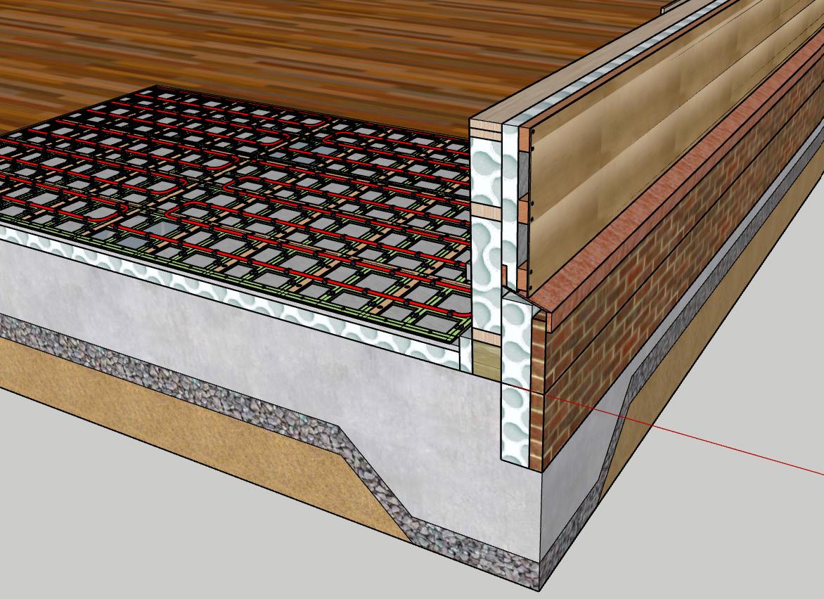
Service cavity inside external and internal walls and floors provide spaces for heating,cooling,mechanical ventilation and electrical services.Heating pipes and hot water pipes are embedded within the floors to provide efficient thermal distribution. Electronic conduits are installed inside the walls for electrical wiring and communication systems.
Cooling pipes, cold water pipes, ventilation ducts, and waste pipes are routed through the ceiling spaces to optimize space and accessibility for maintenance.
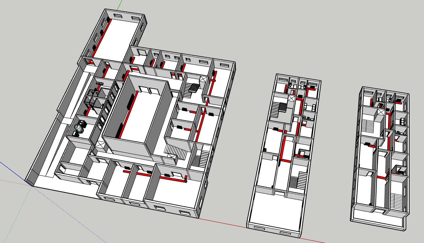
Axonometric Picture
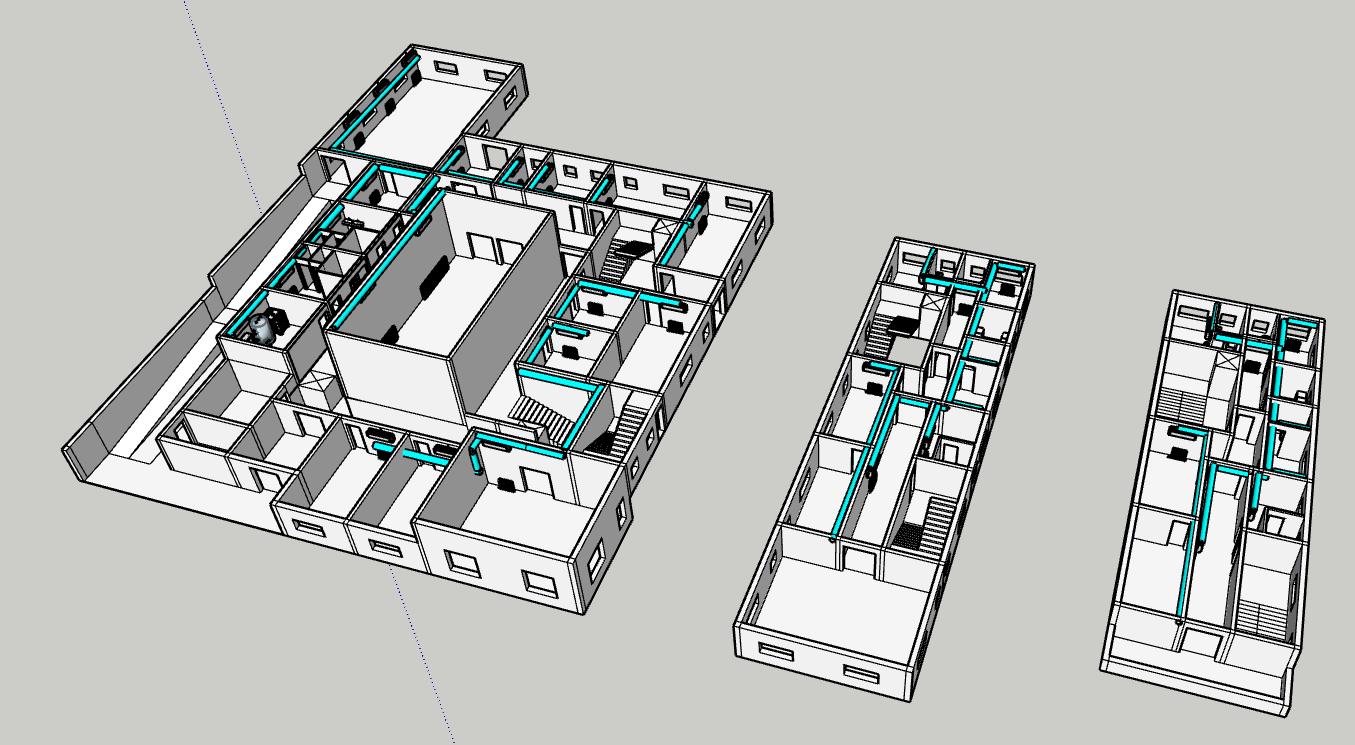
Axonometric Picture
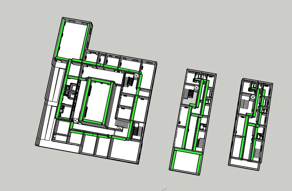
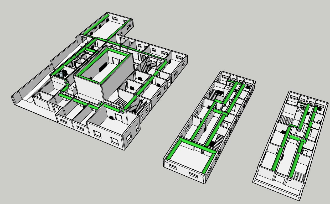
4.9 Building Service-Electrical Conduit System Axonometric Picture
4.9 Building Service-Electrical Conduit in Section Fig 123-125.Electrical Conduit System location marked on ground, intermediate and roof level of 1:20 detailed section B-B.
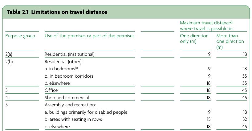
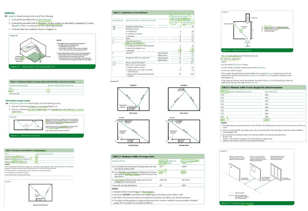
Maximum travel distances are 18 m for single-direction escape and 45 m for two-direction escape in typical buildings(Approved Document B, 2022)
All the spaces except for the art workshop satisfied either requirements of single or two direction escape. Additionally, with the following cases worth mentioning:
Satisfied but deserve improving:
1.Cafe (two-direction escape):
20.4m+3.5m=23.9m by escaping to north main entrance 17.9m+27.8m=45.7m by escaping through community garden
It has just one route satisfying the 45m requirements, but still being compliant.
Improvements for the cafe is rearranging the furnitures to make the distance within cafe become 14.5m, then 14.5m+3.5m=18m by escaping to north entrance and 14.5m+27.8m=42.3m by escaping through community garden, having both routes satisfying the 45m requirements.
2.Event Space (two-direction escape):
15.5m+4.9m+5m=25.4m by escaping to the north entrance
16m+6.8m+9.2m+1.5m+5m=49.5m by escaping to the south side entrance
It has just one route satisfying the 45m requirements, but still being compliant.
To really make both routes satisfying the 45m reequirements, another opening of event space could be designed at the female wc and male wc side.
Then 5m+5m+5m=15m by escaping to the north entrance and 10m+2.4m+5m=17.4m by escaping to the south entrance, having both routes satisfying the 45m requirements.
Unsatisfied:
Art Workshop (single-direction escape):
10.8m+4m+12.5m+5m=32.3m by escaping to the south side entrance.
To make the route satisfying the 18m reequirements, an external opening of art workshop could be designed. to make this case a two-direction escape.Then the shortest route for escaping will be just 9m.
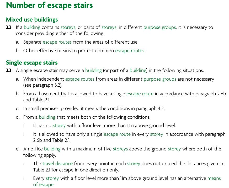
Escape stairs for 'assembly or recreation' building( this is a community art centre)must be protected (minimum 30-minute fire resistance), at least 1100 mm wide, lead to a final exit, and in buildings over 18 m high or with more than 2 storeys, at least two stairs are typically required, with smoke control (e.g. lobbies or pressurization) in taller buildings according to Approved Document B.(Approved Document B, 2022)
I have two stairs for each floor. Both are privately used by the artists living and working in the building, helping them to escape from first and second floor living area, as well as first floor art studio.The main staircase, the one with a lift beside it, is 1625mm (satisfying 1100mm requirements)wide and allows people to travel though the 3m level height, with a platform of 1450m width. The other one ,the firefighting escape stairs, located at the southeast of building is also 1625mm (satisfying 1100mm requirements too)wide and have a platform of 1450mm width.(Approved Document B, 2022)
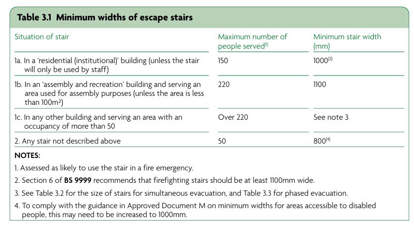
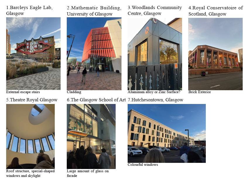
For the firefighting escape stairs, materials of it (clt floor slabs, glulam frame, wood fibre insulation, plywood lining etc.)need to satisfy class A2-s3,d2 or better, which means almost non-combustible (A2), but produces a high amount of smoke (s3) and flaming droplets or particles (d2) when burning.(Approved Document B, 2022)
To achieve the required fire resistance (e.g. REI 60), Glulam frames and CLT floor slabs for stairs should be protected with intumescent coatings approximately 0.3–0.6 mm thick or enclosed within fire-rated plasterboard layers totaling around 25 mm thickness. Plywood lining must be treated similarly with fire retardants or replaced with fire-rated materials. Wood fibre insulation certified as A2-s3,d2 generally does not require additional thickness but must be properly installed.(Approved Document B, 2022)
clear width:1525mm (with handrail 1625mm) riser:150mm
tread:300mm
flight length:1500mm
number of risers:
handrail height:1100mm
headroom:2m
exit door width:2000mm
clear width:1525mm(with handrail 1625mm) riser:150mm
tread:300mm
flightlength:1500mm
number of risers:10
handrail height:1100mm
headroom:2m
exit door width:1000mm
clear width:1525mm (with handrail
riser:150mm
tread:300mm
flight length:1500mm
number of risers:
handrail height:1100mm
headroom:2m
exit door width:2000mm
clear width:1525mm(with handrail 1625mm)
riser:150mm
tread:300mm
flightlength:1500mm
number of risers:10
handrail height:1100mm
headroom:2m
exit door width:1000mm
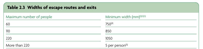
Exit routes must be unobstructed, clearly signed, at least 1050 mm wide for up to 200 people, and lead directly to a place of safety such as an assembly point located a safe distance from the building according to Approved Document B.(Approved Document B, 2022)
I used purple lines to mark all the exit routes for every space in the buildings, red words showing entrances names and exit name, purple words showing assembly point names. The building has three entrances which act as exits at the same time, main entrance at the north, side entrance at the south and private entrance at the east, and additionally an emergency exit at the east too. Each entrance links to an assembly point. Each assembly point is big enough. The distance between exit and assembly point is a safe distance without obstacles.
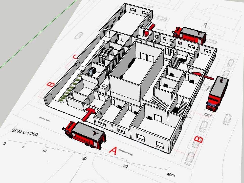
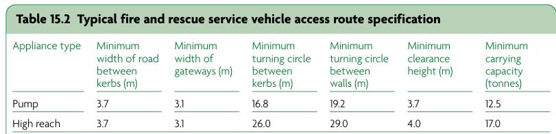
Firefighting appliances such as fire mains and hydrants must be provided in buildings over 18 m (dry riser) or 50 m (wet riser) tall, with fire hydrants within 90 m of entrances and located so fire service vehicles can get within 18 m according to Approved Document B.
I used red lines to mark the car lane surrounding the building, red circle to mark the reserved emergency vehicle spaces, brown lines to mark the route of firefighters going into the building and going upstairs.
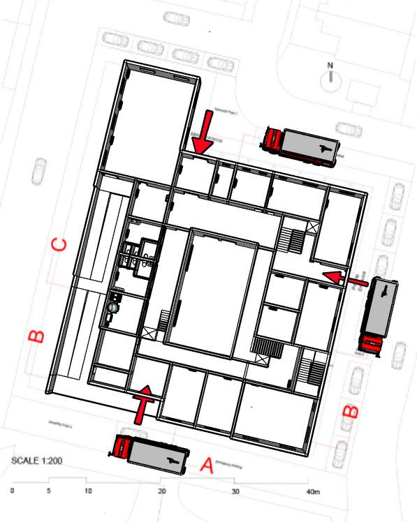
Spaces for firefighting vehicles parking is wide enough(4.4m), wider than required 3.7m by Approved Document B.
Since the highest point of my building is 9m from ground (building topography: +100m~+109m for northeast part of the building), fire hydrants are not necessary for this building. Besides, firefighting vehicles are close enough to the building, much closer than the required 18m by Approved Document B. (Approved Document B, 2022)
The nearest fire station, Newcastle Central Community Fire Station is just a 5-minute-ride away. Firefighting vehicles drive through Westgate Rd and A186 to the site as the quickest access.
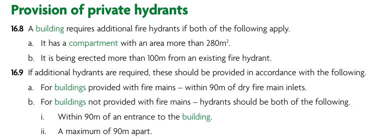
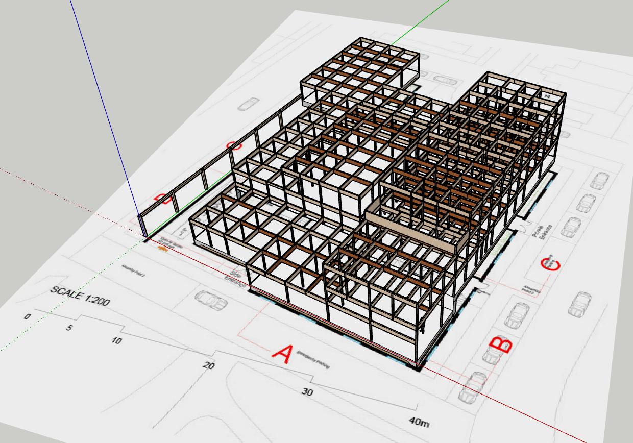
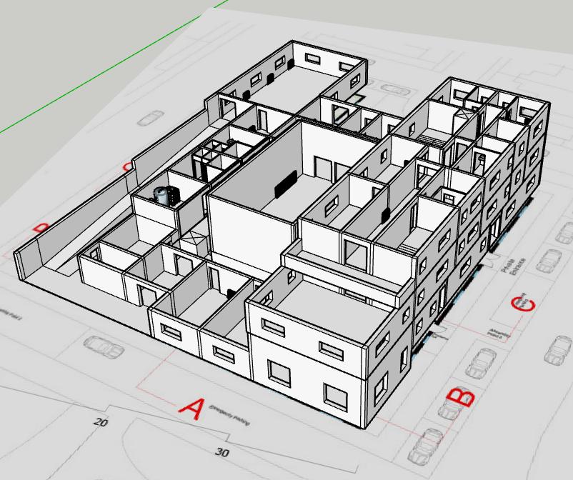
Due to the presence of a compartment exceeding 280 m² (compartmentation A shown on page 65), the building is required to provide private hydrants in accordance with fire safety regulations. To comply with this requirement, three private hydrants have been strategically installed near each main exit point. The placement ensures that no part of the building is more than 90 metres away from a hydrant, thus facilitating efficient firefighting operations and rapid water supply access in case of fire.(Approved Document B, 2022)
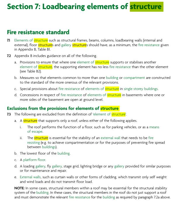
The building’s structural components have been carefully designed to meet the fire resistance criteria set out in Approved Document B. The ground floor concrete slab inherently provides excellent fire resistance due to its noncombustible nature, requiring minimal additional protection. In contrast, the CLT floor slabs and Glulam columns and transferring beams, being timber-based materials, are more susceptible to fire; therefore, they are protected with certified fire-resistant coatings or fire-rated cladding systems to achieve the required fire resistance rating, typically REI 60. (Approved Document B, 2022)
This ensures that the structural integrity and load-bearing capacity are maintained for the necessary duration during a fire event, allowing safe evacuation and effective firefighting. Furthermore, the green roof assembly is designed and installed in a manner that does not compromise the roof’s fire resistance or the overall structural fire performance, incorporating fire-retardant layers where necessary to prevent fire spread from external sources.
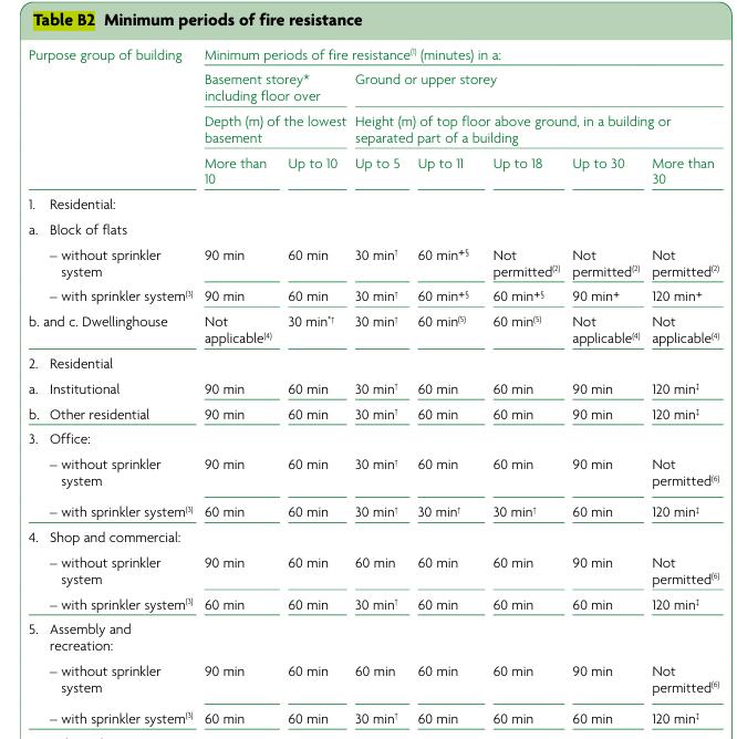
For assembly or recreation buildings with a sprinkler system installed, structural elements must achieve at least 30 minutes of fire resistance if the floor height does not exceed 5 metres.(Approved Document B, 2022)
My overall fire protection strategy made sure all main load-bearing parts meet the 30-minute fire(with sprinkler system) resistance requirement( Approved Document B 2022). The glulam frame and CLT floors rely on timber’s natural charring ability to keep strong during a fire, following BS EN 1995-1-2 standards. These elements are sized so that even after some charring, enough material remains to hold up the structure. The concrete slab at the ground floor acts as a non-flammable base. I also divide the building into fire zones to slow down fire spread, and design clear, safe escape routes with stairs and lifts for emergency use. The layout helps people evacuate quickly and safely, following fire safety rules.
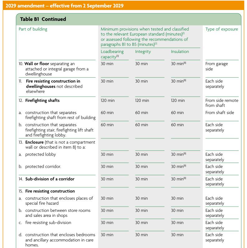
To achieve the required fire resistance (e.g. REI 60), Glulam frames and CLT floor slabs for building should be protected with intumescent coatings approximately 0.3–0.6 mm thick or enclosed within fire-rated plasterboard layers totaling around 25 mm thickness. Plywood lining must be treated similarly with fire retardants or replaced with fire-rated materials. Wood fibre insulation certified as A2-s3,d2 generally does not require additional thickness but must be properly installed.(Approved Document B, 2022)
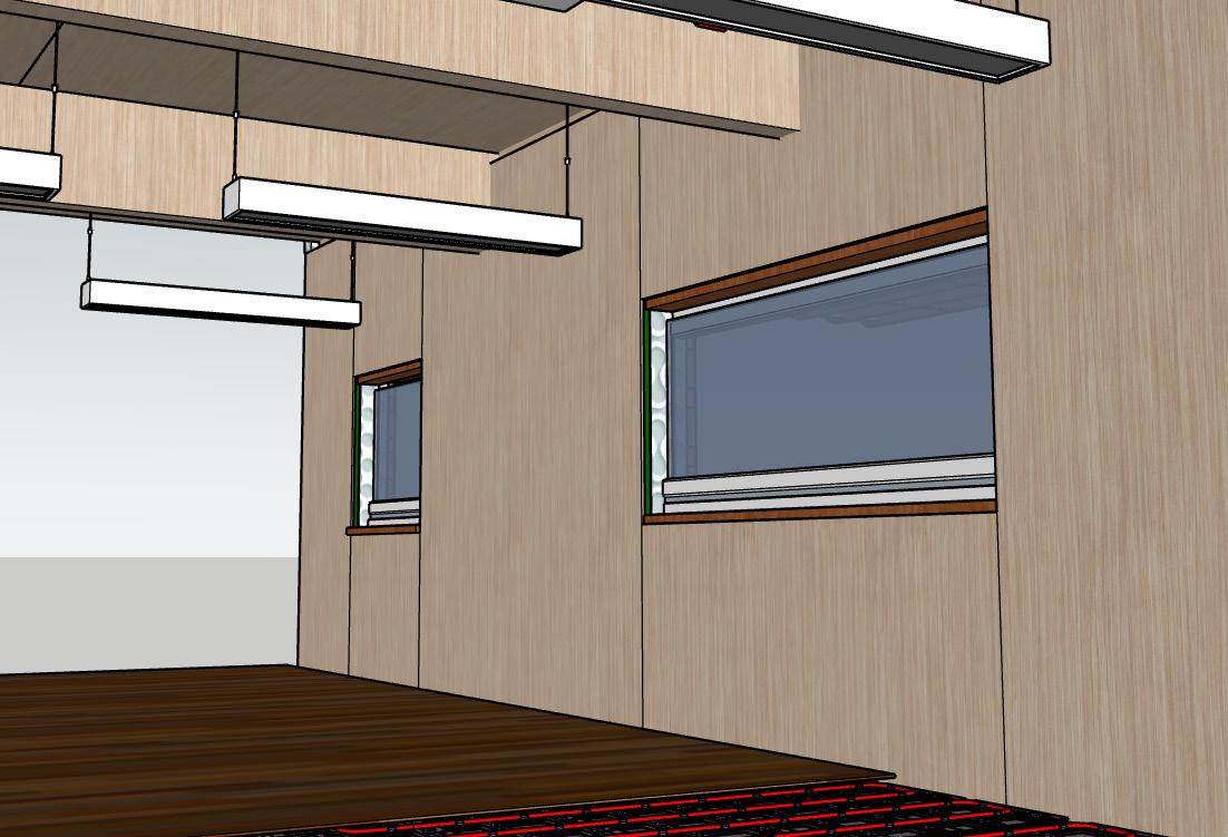
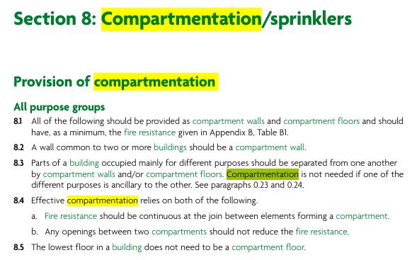
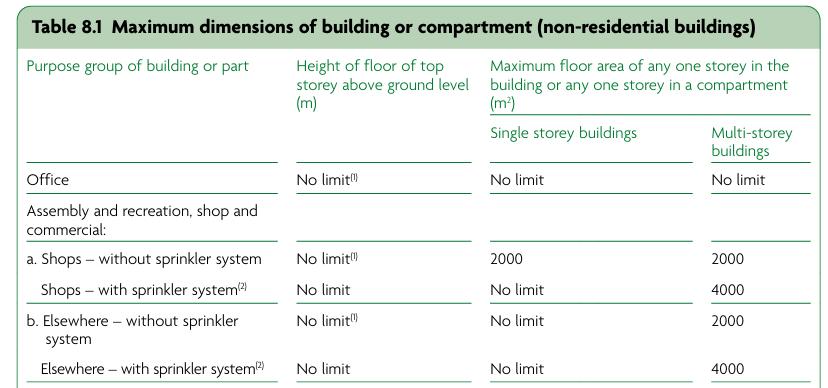
Whether a sprinkler system is required largely depends on the building’s compartmentation. According to Approved Document B (Volume 2), if any fire compartment exceeds 280 m² in floor area, an automatic sprinkler system is generally mandatory to enhance fire safety. In this building, at least one compartment surpasses this threshold, so a sprinkler system has been installed accordingly.(Approved Document B,2022)
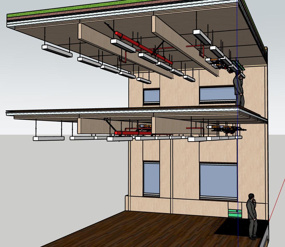
The sprinklers are positioned at ceiling level within the relevant spaces to provide effective coverage. Conveniently, the system connects directly to the existing cold water pipes routed through the ceiling void, ensuring reliable and efficient water supply for fire suppression.
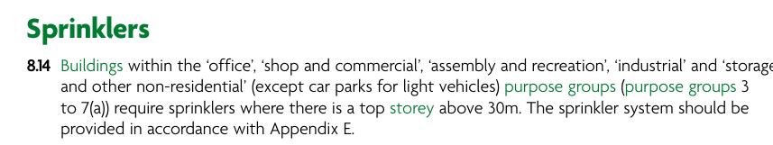

According to Approved Document B, for recreational buildings like this building, the maximum allowed compartment sizes are: 2000 m² for single-storey compartments 1000 m² per compartment for buildings with more than one storey (Approved Document B,2022)
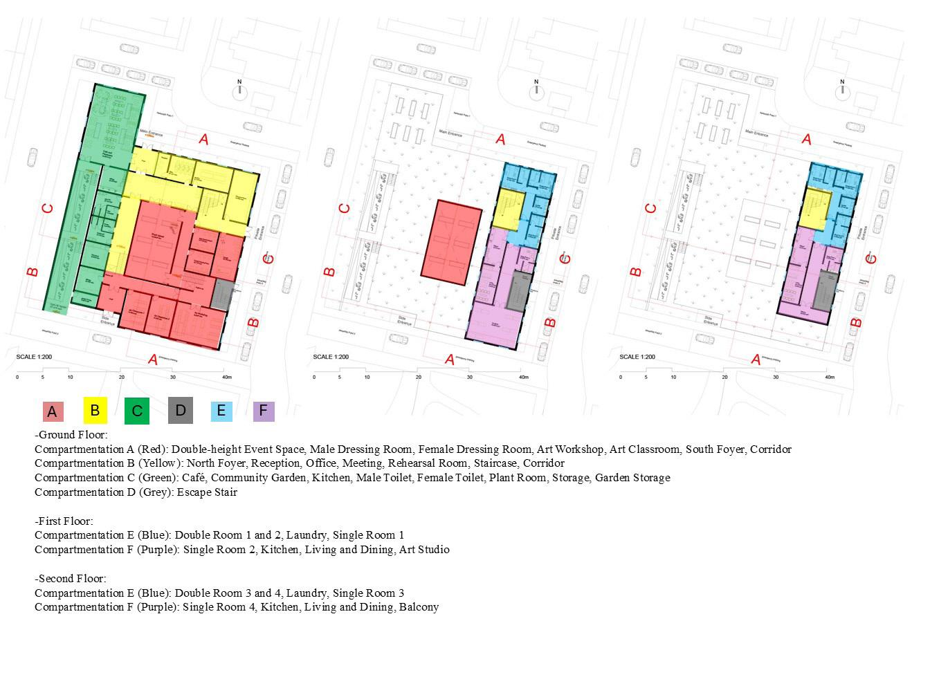
All compartments in this design are safely within these limits. High-risk spaces like kitchen and plant room are separated into different zones, and the double-height event space and its associated spaces (dressing rooms and workshop) is treated as its own compartment with fire-resistant walls and floors. Staircases and lift areas are enclosed with fire-rated construction.


iii) How have you arrived at a decision on the best method of providing access?
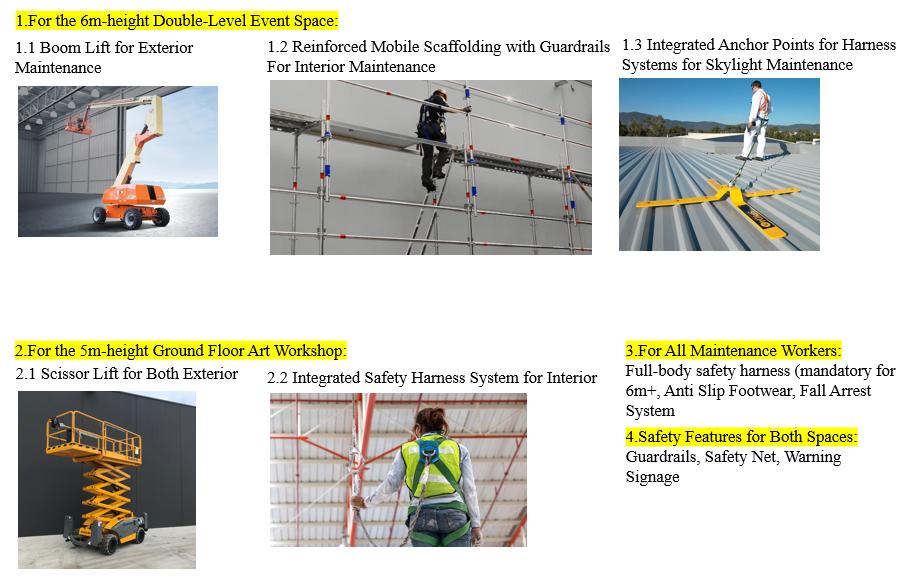
Boom lift chosen for efficient and safe access to the exterior of the event space.
Reinforced mobile scaffolding with guardrails for safe indoor access in the event space.
Integrated anchor points installed on all skylights and green roof areas to facilitate safe harness use.
Scissor lifts with harness systems selected for the art workshop’s indoor maintenance.
All solutions comply with the Construction (Design and Management) Regulations 2015 (CDM 2015), which require designers and contractors to reduce risks by incorporating safe access and maintenance strategies during design and construction stages. Specifically, CDM 2015 mandates avoiding hazardous work at height wherever possible, providing safe and manageable access routes (such as guardrails, anchor points, and mechanical lifts), and ensuring proper safety management and training for maintenance personnel.
These decisions prioritize regulatory compliance, practical maintenance needs, and worker safety to minimize risks during both frequent and occasional tasks.
i) What are the critical/most challenging areas in your project that will require access for use/maintenance?
The indoor event space at 6 m- height in the building center, where working at height poses significant risks.
The exterior of the 6m event space for façade maintenance.
The 5m -height high art workshop on the ground floor, including indoor ceiling maintenance and outdoor facade work at elevated heights.
Green roof areas at 3mand 9 m heights, requiring regular maintenance of vegetation and equipment, with the 9-m roof being more challenging.
Skylights above the event space and the 3-m rooftop skylight at the ground floor café that require safe access for cleaning and repairs.
ii) What options have you examined for providing access?
Exterior of the 6m event space: boom lift for façade and roof work.
Interior of the 6m event space: reinforced mobile scaffolding with guardrails.
Skylights (including the café’s 3m rooftop) and green roof areas: integrated anchor points for safe harness attachment.
5m art workshop interior: scissor lift combined with an integrated harness system for fall protection.
Use of personal protective equipment (PPE), fall arrest systems, and guardrails as safety measures throughout.
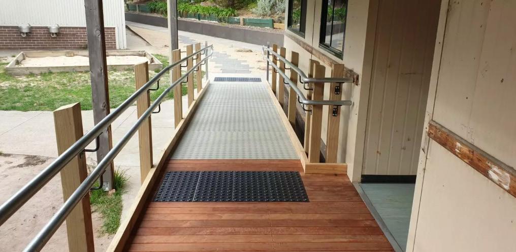
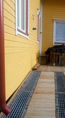
2.Slip and fall risk on outdoor ramps during rainy and snowy weather
i) What are the critical/most challenging areas in your project that will require access for use/maintenance?
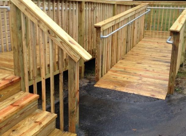
The long wooden ramps connecting different levels in the open-air garden, which are prone to becoming slippery due to water accumulation and ice formation during rainy and snowy conditions, significantly increasing the risk of slips and falls.
ii) What options have you examined for providing access?
Applying anti-slip treatments suitable for wooden surfaces, such as non-slip coatings or textured strips.
Installing effective drainage systems and partial overhead coverings to reduce water pooling on the wooden ramps.
Adding handrails and clear warning signage to enhance user safety.
iii) How have you arrived at a decision on the best method of providing access?
Anti-slip surface treatments specifically designed for wood combined with proper drainage were selected as the most effective and practical approach.
Handrails and warning signs are installed to further reduce slip risks.
Snow removal procedures will be conducted during severe weather to maintain safety. All measures comply with the Construction (Design and Management) Regulations 2015 (CDM 2015), which require that designs and maintenance plans minimize slip and fall hazards by considering environmental conditions and providing safe, accessible routes for all users.

i) What are the critical/most challenging areas in your project that will require access for use/ maintenance?
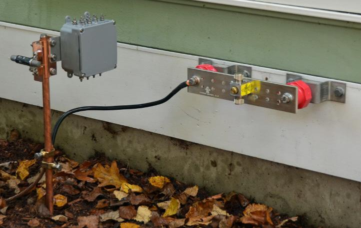
The plant room contains multiple mechanical and electrical systems in a confined space, posing risks of electrical faults and shock hazards during maintenance.
ii) What options have you examined for providing access?
Providing dedicated maintenance access routes and inspection hatches to allow safe servicing of equipment.
Ensuring proper separation between wet zones and electrical equipment to prevent hazards. Installing grounding systems and Residual Current Devices (RCDs) to protect against electrical shocks. Using waterproof and dustproof electrical components along with effective cable management.
iii) How have you arrived at a decision on the best method of providing access?
The design incorporates dedicated maintenance spaces and safe access paths in compliance with relevant safety standards.
Clear separation between wet and electrical areas is implemented with protective barriers. Electrical safety devices such as RCDs are installed to minimize shock risks to maintenance personnel. Regular inspection and maintenance schedules are planned to uphold ongoing safety.
All solutions comply with the Construction (Design and Management) Regulations 2015 (CDM 2015), which require that risk assessments and management measures be in place to protect workers from electrical hazards during maintenance and operation, including appropriate design to separate electrical and wet zones, installation of protective devices, and safe access provisions.
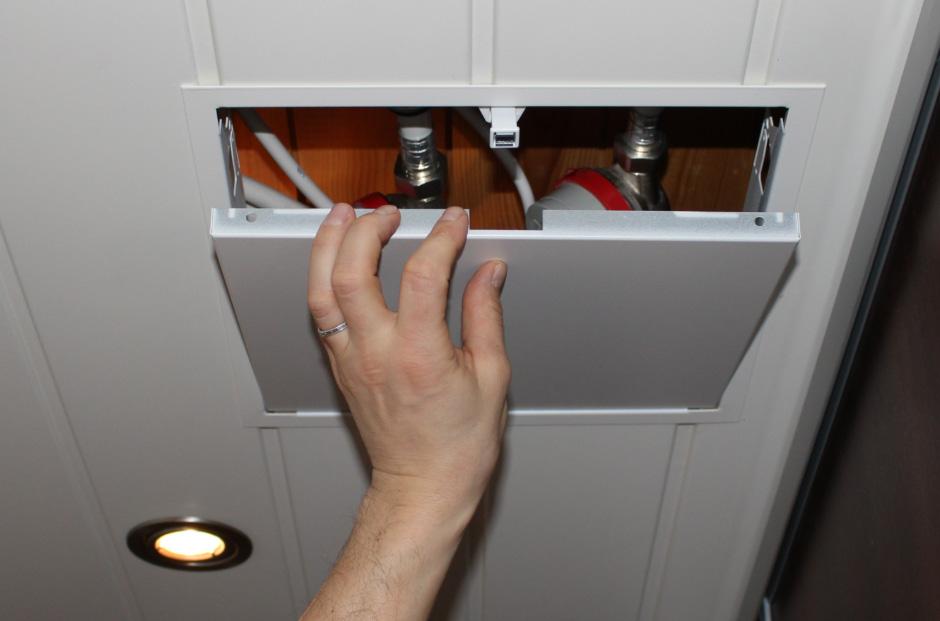
Inspection Hatch for Plant Room

for
7.Assembly- 7.1 1:20 Part Section, Part Plan, Part Elevation
*Original Size of Drawing Attached


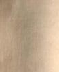

Fig 184. 1:20 Detailed Section, Part Plan and Part Elevation.
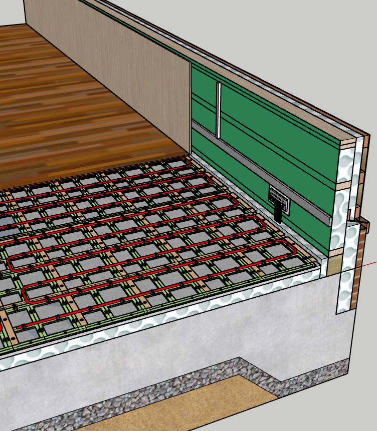
7.1 How are the various constituent parts of your building assembled and supported?
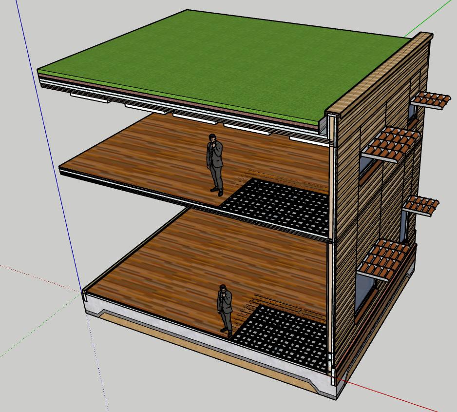
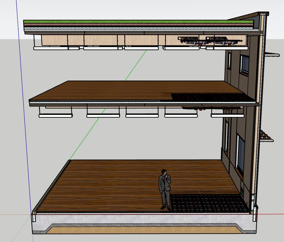
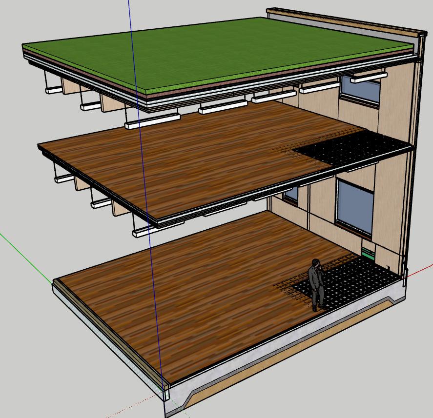
The building is assembled using a timber structural system combining CLT roof and floor panels with glulam columns and transferring beams.
External walls consist of a glulam and wood fibre insulation core, finished externally with zinc cladding fixed to battens.
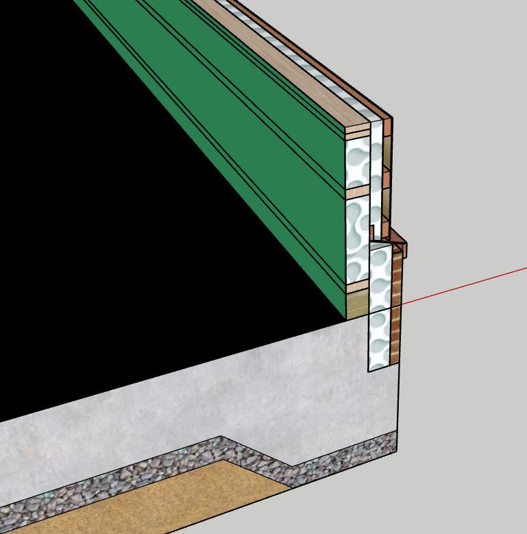
The roof build-up includes CLT, vapour control layers, wood fibre insulation, and a green roof system.
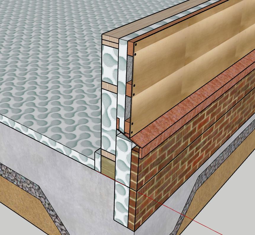
The ground floor comprises a concrete slab over XPS insulation and a hardcore base, with internal layers including wood fibre insulation, acoustic underlay, and plywood finish.
All components are prefabricated where possible and assembled on site using dry construction techniques, allowing efficient load transfer and integration of insulation and services within the construction build-ups.
*Original Size of Drawing Attached
*Original Size of Drawing Attached
7.2 In what sequence is your building constructed? Are there any factors in your choice of typology or site that require a particular sequence?
The building is constructed in a coordinated sequence beginning with site preparation and excavation to accommodate the 2-metre level change (+98m to +100m).
A stepped or split-level concrete slab is cast over compacted hardcore to provide a stable base. Glulam columns are then installed, followed by prefabricated CLT floor and roof panels. The early installation of the roof allows for a sheltered working environment for follow-on trades.
External wall build-ups—including wood fibre insulation, breather membranes, and zinc cladding—are applied once the structure is weathertight.
The green roof layers are then installed above the CLT roof. Internal services and partitions are completed last.
The use of prefabricated timber elements allows for fast, dry construction, which is especially beneficial on a site with level changes and limited flat working space.
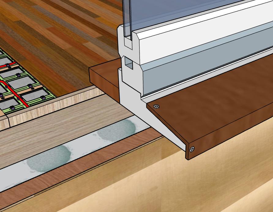
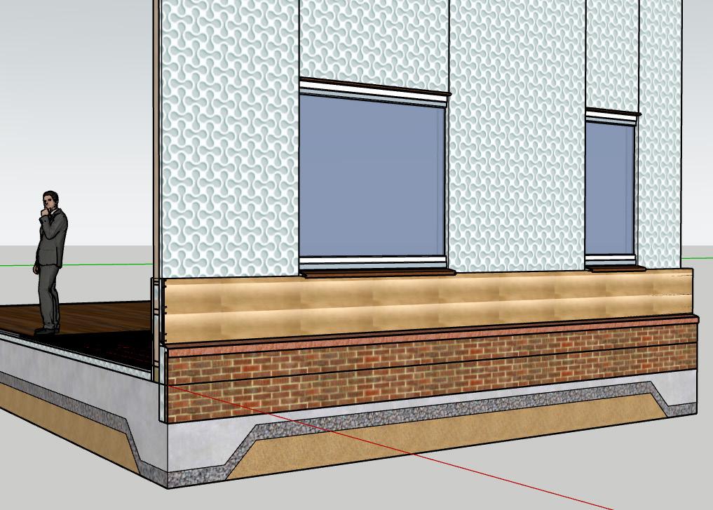
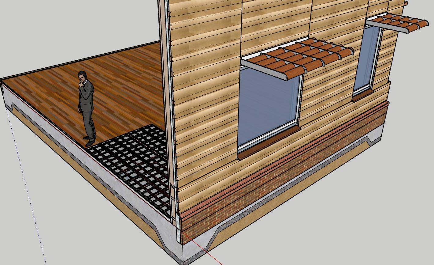
7.3 Describe using no more than 300 words, and with reference to your 1:20 drawings, how the design of your external fabric has shaped the character and atmosphere of your building.
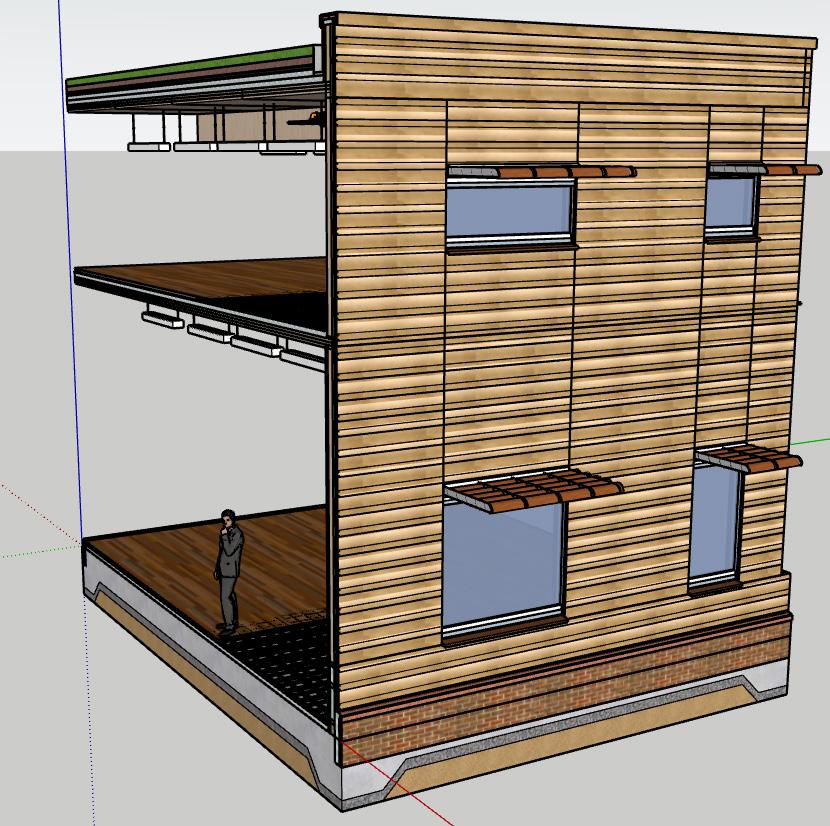
The external fabric, shown in the 1:20 section through the ground floor workshop, first floor studio, and green roof above, is a breathable timber wall construction clad in a pale yellow zinc finish. Internally, the walls are lined with plywood, contributing to a natural and warm interior atmosphere that supports creativity and focus.
The unusual pale yellow zinc cladding not only gives the building a distinctive and inviting appearance but also reflects heat in summer, reducing thermal gain. This bright, soft-metal finish complements the identity of a community art centre—welcoming, contemporary, and slightly unconventional.
The wall build-up includes modest-sized windows that bring in balanced natural light, while the wall’s depth and materials suggest both robustness and care in construction. Above, the green roof improves performance and connects the building visually to nature. The second-floor balcony, though not sectioned, contributes to a layered and active facade.
Together, these elements shape an architecture that is light yet grounded, precise yet warm. The design of the external fabric goes beyond thermal performance to define the character and atmosphere of the spaces within.
(Word Count:231)
Initial Site Analysis
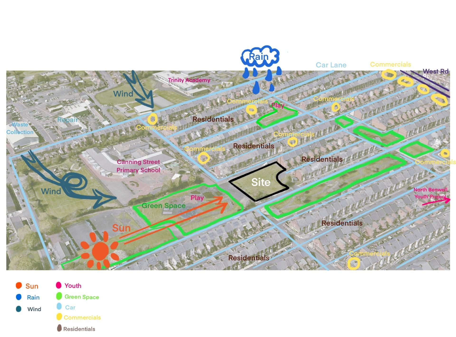
Site Plan
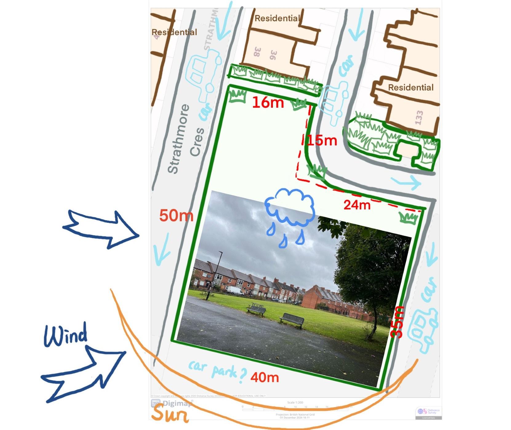
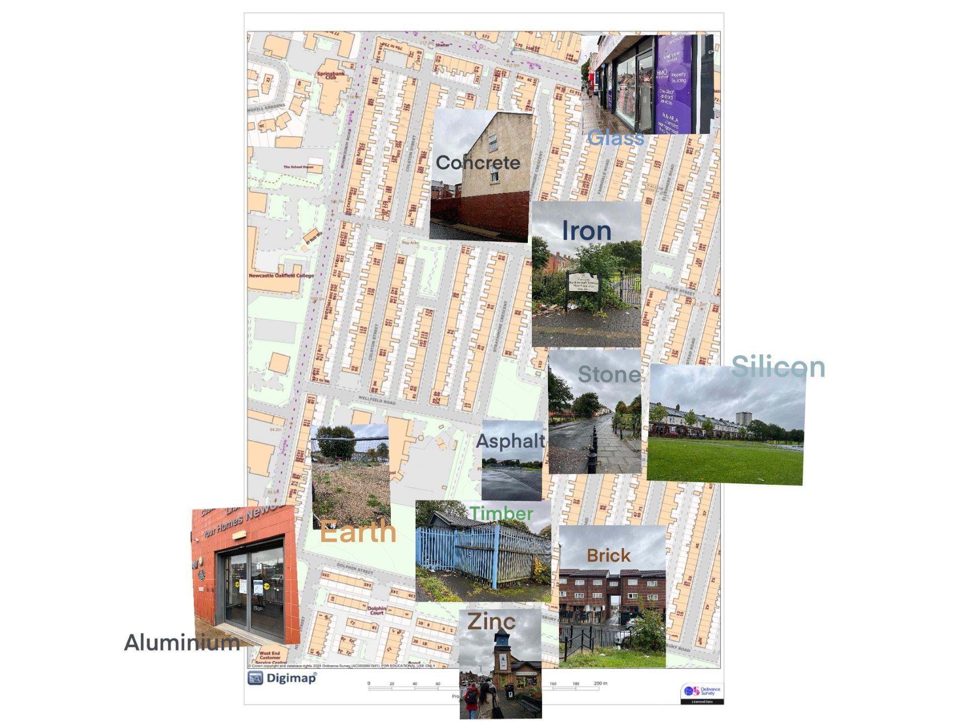
Materials around the Site
Precedents for Structure from Field Trip
Design Strategies (Semester 1)-Heating and Ventilation, Fire and Life Safety
Precedents for Heating and Ventilation References for Relevant Firefighting Regulations
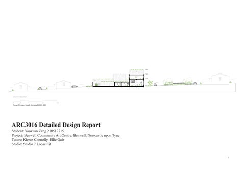
Cover Picture: South Section B-B 1:400. Author's own drawing.
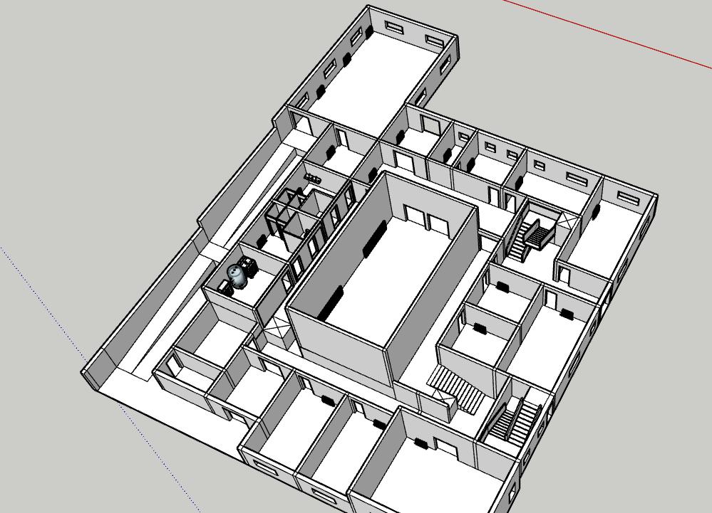
Fig.1 Site SketchUP Model. Author's own work.
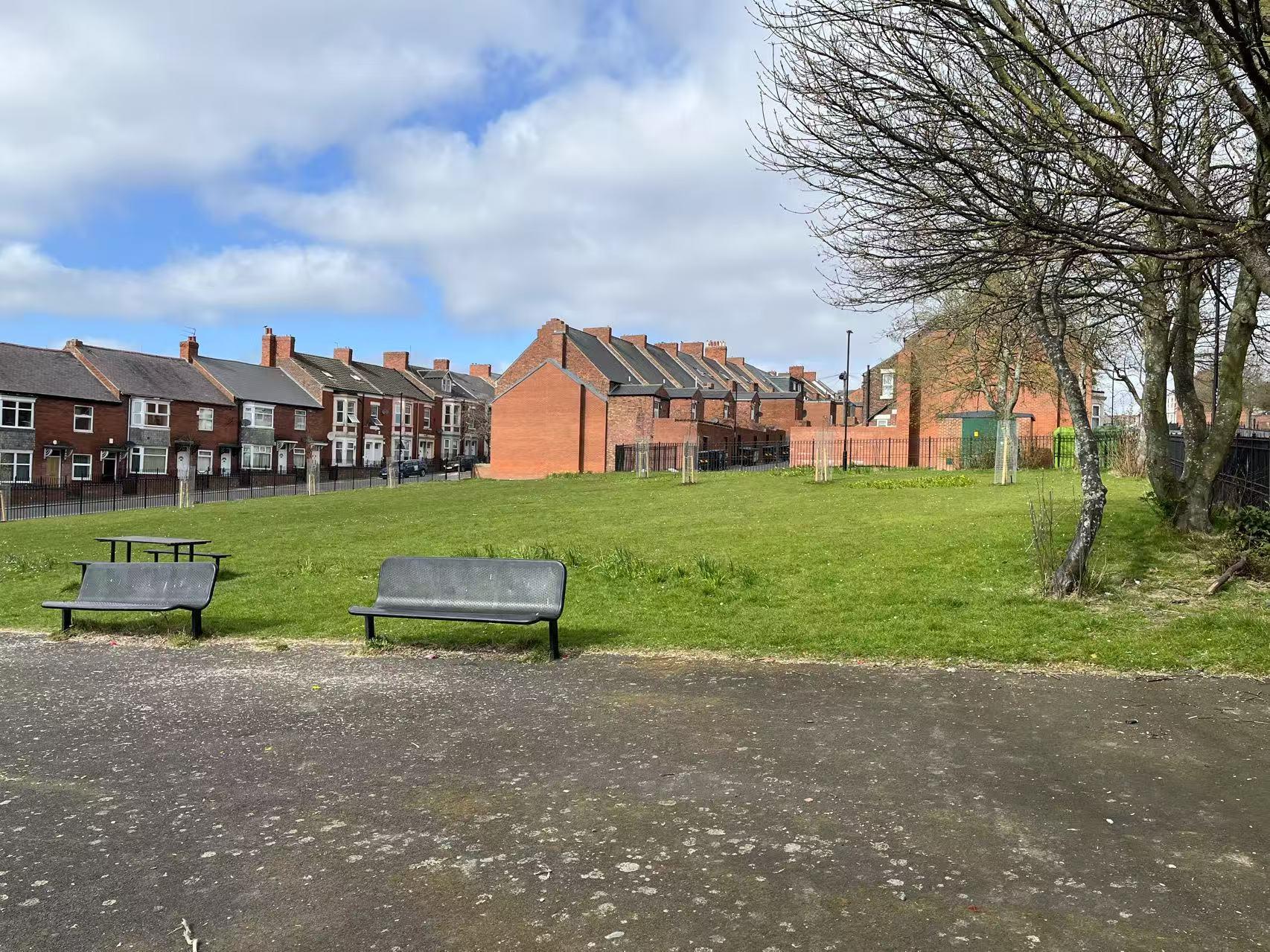
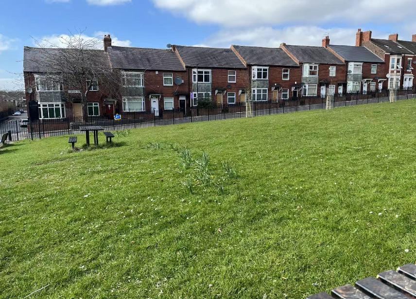
Fig.2. South View of Site. Author's own photo.
Fig.3. North View of Site. Author's own photo.
Fig.4. East View of Site. Author's own photo.
Fig.5.West View of Site. Author's own photo.
Fig 6. Site Plan 1:500. Author's own drawing.
Fig 7.Ground Floor Plan 1:200. Author's own drawing.
Fig 8.First Floor Plan 1:200. Author's own drawing.
Fig 9. Second Floor Plan 1:200. Author's own drawing.
Fig 10.Roof Plan 1:200. Author's own drawing.
Fig 11. Long West Elevation A-A 1:200. Author's own drawing.
Fig 12. Long West Section A-A 1:200. Author's own drawing.
Fig 13.Long South Elevation B-B 1:200. Author's own drawing.
Fig 14.Long South Section B-B 1:200. Author's own drawing.
Fig 15. Long South Section C-C 1:200. Author's own drawing.
Fig 16. West Section A-A 1:100. Author's own drawing.
Fig 17. South Section B-B 1:100. Author's own drawing.
Fig 18.South Section C-C 1:100. Author's own drawing.
Fig 19-26. Material Palette. zinc cladding ASTURIANA DE LAMINADOS, (2025). Zinc Cladding [photograph]. [Viewed 15 May 2025]. Available from: https://www.archiexpo.com/architecture-design-manufacturer/zinccladding-2959.html
glulam frame
Element 5., (2025). Glulam [photograph]. [Viewed 15 May 2025]. Available from: https:// elementfive.co/products/glulam/
clt floor slab and roof deck
View Floor, (2022). Cross Laminated Timber Floor Panels [photograph]. [Viewed 15 May 2025]. Available from: https://viewfloor.co/cross-laminated-timber-floor-panels/
plywood lining
Place Makers, (no date). Radiata Plywood Non-Structural Grooved Lining Untreated 2400 x 1200 x 12mm [photograph]. [Viewed 15 May 2025]. Available from: https://www. placemakers.co.nz/online/timber-plywood/plywood/lining-plywood-interior/lining-plywoodinterior/radiata-plywood-non-structural-grooved-lining-untreated-2400-x-1200-x-12mm/ p/2420321
wood fibre insulation
Natural Insulations, (2025). Steicoflex Wood Fibre Insulation [photograph]. [Viewed 15 May 2025]. Available from: https://naturalinsulations.co.uk/product/steicoflex-insulation/
mineral wool insulation
TruTeam, (2025). (TruTeam 2025) [photograph]. [Viewed 15 May 2025]. Available from: https://www.truteam.com/insulation-installation/mineral-wool-insulation/
concrete slab foundation
Stacy, (2024). The Ultimate Guide to Understanding Concrete Slab Foundations [photograph]. [Viewed 15 May 2025]. Available from: https://www.houseidea.com/blog/understandingconcrete-slab-foundations/
hardcore
WWilts, (2021). Compaction of hardcore under slab [photograph]. [Viewed 15 May 2025]. Available from: https://forum.buildhub.org.uk/topic/22985-compaction-of-hardcore-underslab/
Fig 27-32. Group Discussion Notes. Author's own photo.
Fig 33. Rammed Earth Making Process. Author's own drawing.
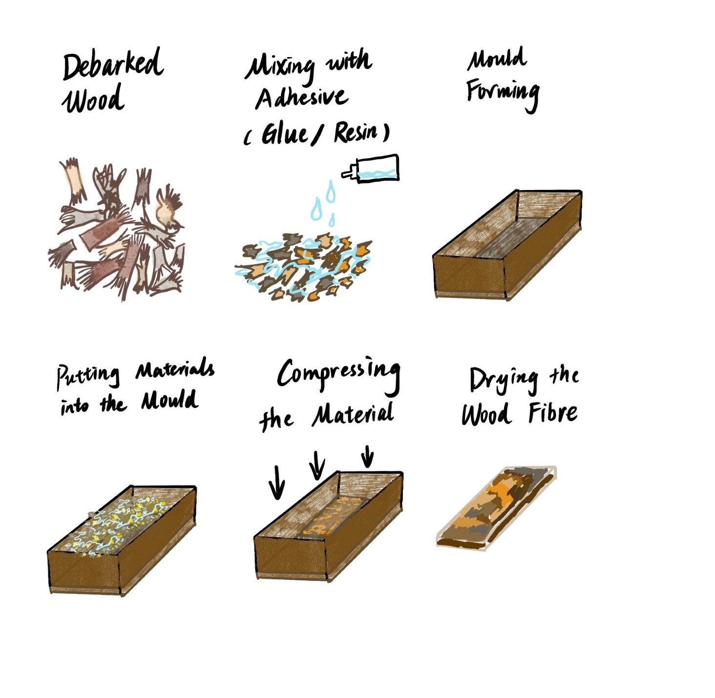
Fig 34. Wood Fibre Making Process. Author's own drawing.
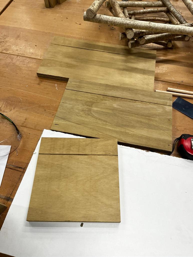
Fig 35-44. 1:1 Group Model Making Process. Photographed by Angus Donald.
Fig 45-46. SketchUp Model of Group Model. Author's own work.
Fig 47. 1:1 Group Model Making Final Outcome. Author's own photo.
Fig 48-49. Close-up Image of Wood Fibre and Rammed Earth. Photographed by Zoe Hill.
Fig 50. Building Model. Author's own work.
Fig 51.Building Structure Model. Author's own work.
Fig 52.Building Structural Bay Model. Author's own work.
Fig 53-56.Building Structural Bay Model from different perspectives. Author's own work.
Fig 57. Concrete Foundation with DPM (black). Author's own work.
Fig 58. Floor insulation added. Author's own work.
Fig 59. Heating and hot water pipes added at service cavity on the floor. Author's own work.
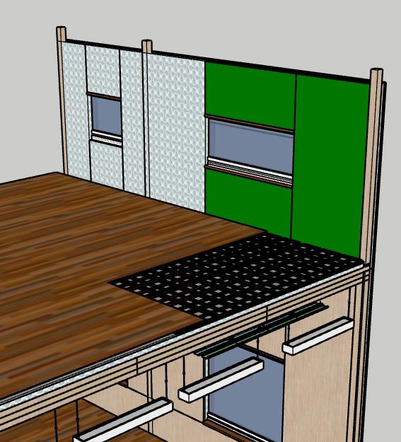
Fig 60. Electrical conduit added at service cavity in wall,and plywood lining for interior added.
Author's own work.
Fig 61. Double glazed window details. Author's own work.
Fig 62. Wall insulation added. Author's own work.
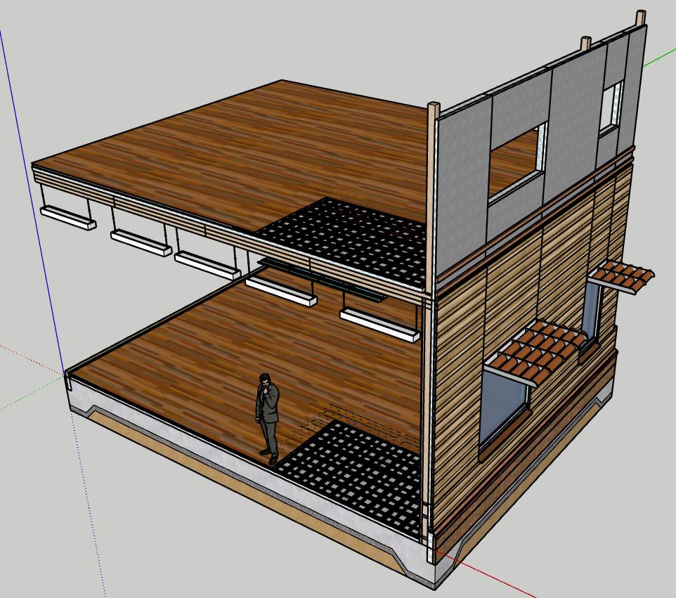
Fig 63. Zinc cladding for exterior and flying brise soleil for sun shading. Author's own work.
Fig 64. Intermediate level floor and wall built with lighting and other services attached. Author's own work.
Fig 65. VCL(green) and insulation added for intermediate level wall. Author's own drawing.
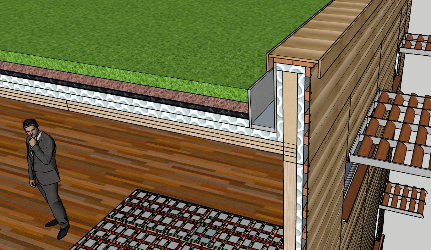
Fig 66. Roof level CLT deck built. Author's own work.
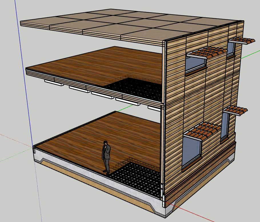
Fig 67. Green Roof details and parapet details. Author's own work.
Fig 68. Ground Floor Structure. (Yellow-Primary Structure, Brown-Secondary Structure). Author's own work.
Fig 69.First Floor Structure added. Author's own work.
Fig 70.Second Floor Structure added. Author's own work.
Fig 71-76 Site Plan 1:500 with Location of Photos on site marked.
Author's own work and photos.
Fig 77. Ground Floor Plan with Community Garden highlighted in dark green, green belts highlighted in light green. Author's own work.
Fig 78.Roof Plan with Green Roof highlighted in light green. Author's own work.
Fig 79.Grey water recycling system in plant room.
Salt, (2015). Grey Water Recycling & Demineralization (DM) Plant [photograph]. [Viewed 15 May 2025]. Available from: https:// deccanwatertreatment.com/demineralization-dm-grey-watertreatment-company-pune-india/
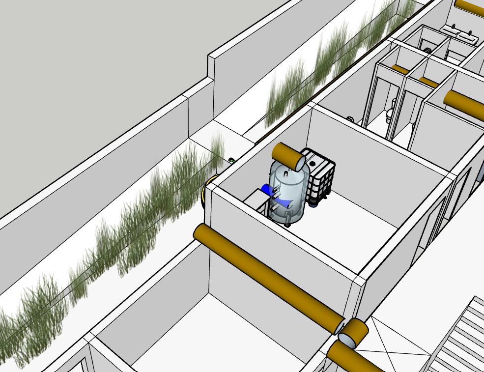
Fig 80. Axonometric picture of grey water recycling system on ground, first and second floor. Author's own work.
Fig 81.Plant Room location with water tank. Author's own work.
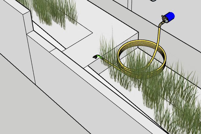
Fig 82. Community Garden irrigation. Author's own work.
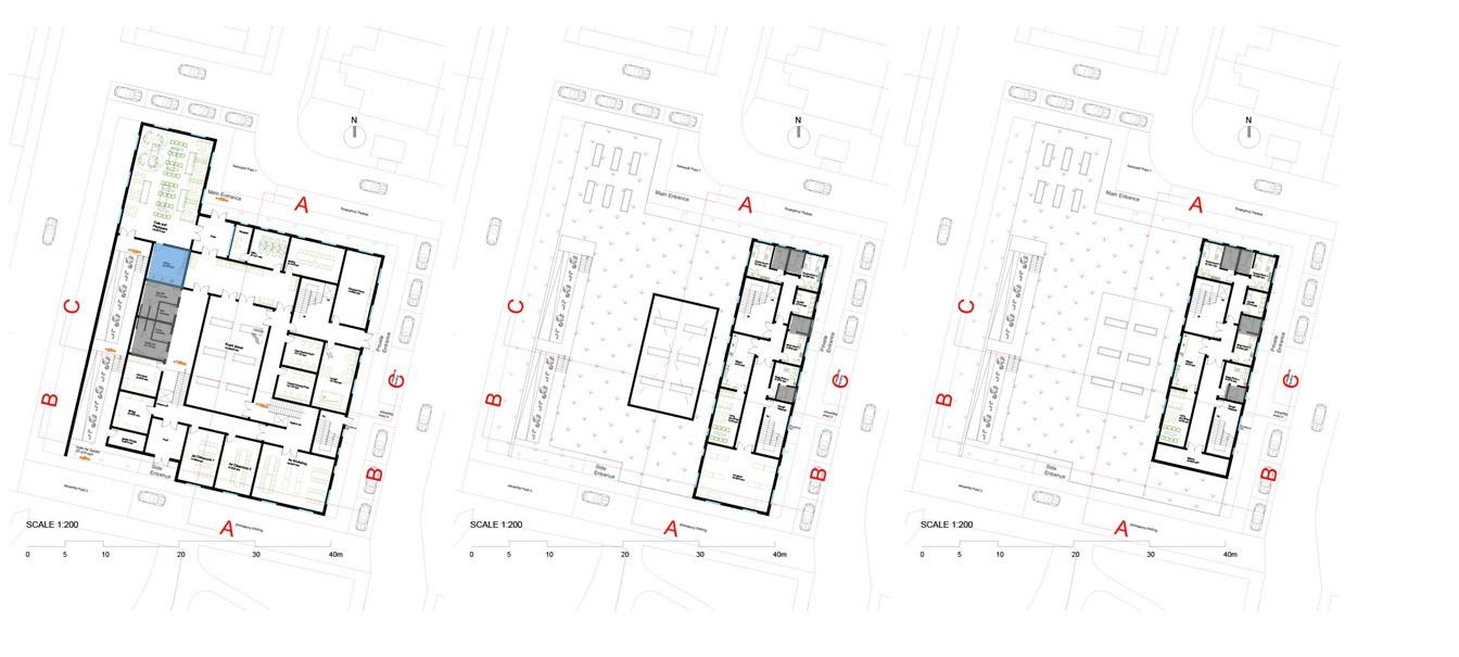
Fig 83-85.Ground, first, second floor plans with plant room highlighted in red, ground floor public toilets, first floor and second floor toilets highlighted in grey and ground floor kitchen highlighted in blue. Author's own work.
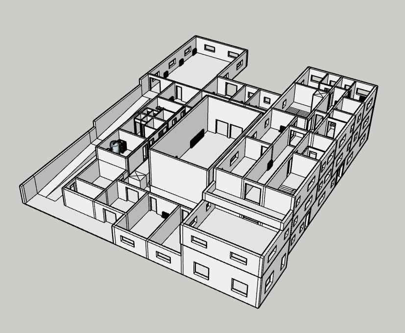
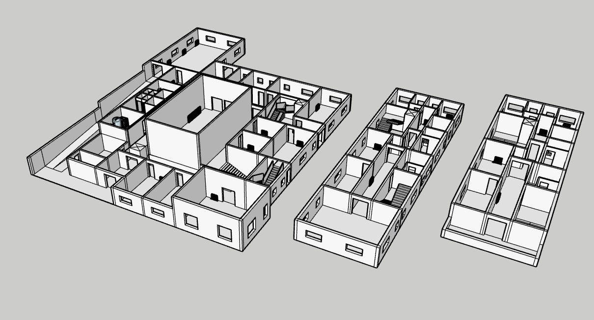
Fig 86.Buildiing model. Author's own work.
Fig 87.Buildiing model-ground, first and second floor. Author's own work.
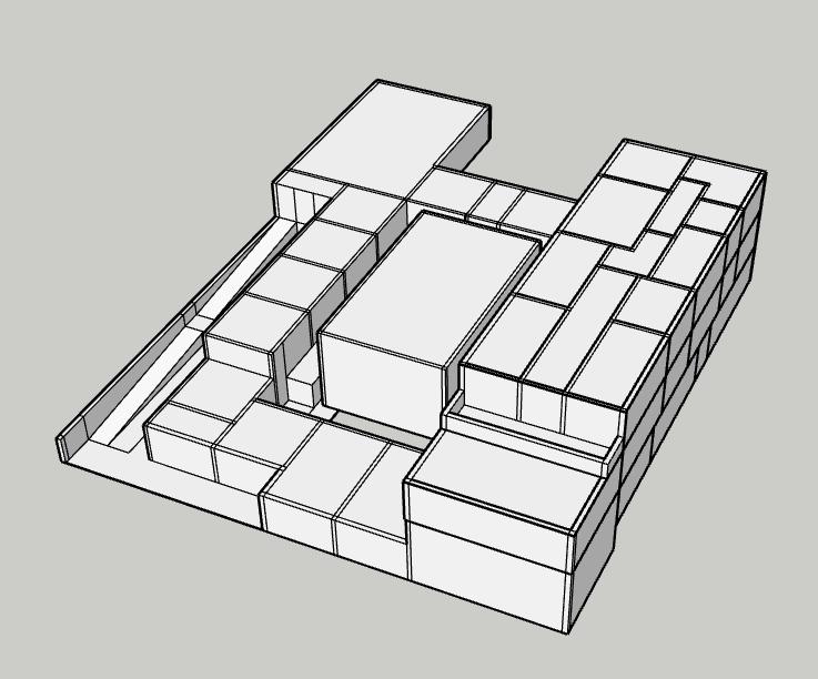
Fig 88.Building massing. Author's own work.
Fig 89. Uvalue requirements in Document L. Approved Document L, Conservation of fuel and power [online], (2021). gov.uk . [Viewed 14 May 2025]. Available from: https:// assets.publishing.service.gov.uk/media/63d8edbde90e0773d8af2c98/ Approved_Document_L__Conservation_of_fuel_and_power__ Volume_2_Buildings_other_than_dwellings__2021_edition_ incorporating_2023_amendments.pdf
Fig 90. Uvalue calculation for External Wall on intermediate level of buildiing.
Author's own work.
Fig 91. 1:5 Detail Section of External Wall on intermediate level. Author's own work.
Fig 92-95.Heating/Cooling Diagram in Summer Day, Summer Night, Winter Day and Winter Night. Author's own drawings.
Fig 96. Sun angle and Shading in Detailed Section. Author's own drawing.
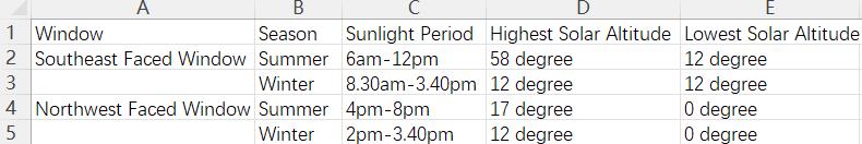
Fig 97. Excel chart showing data of solar altitudes in different time. Author's own work.
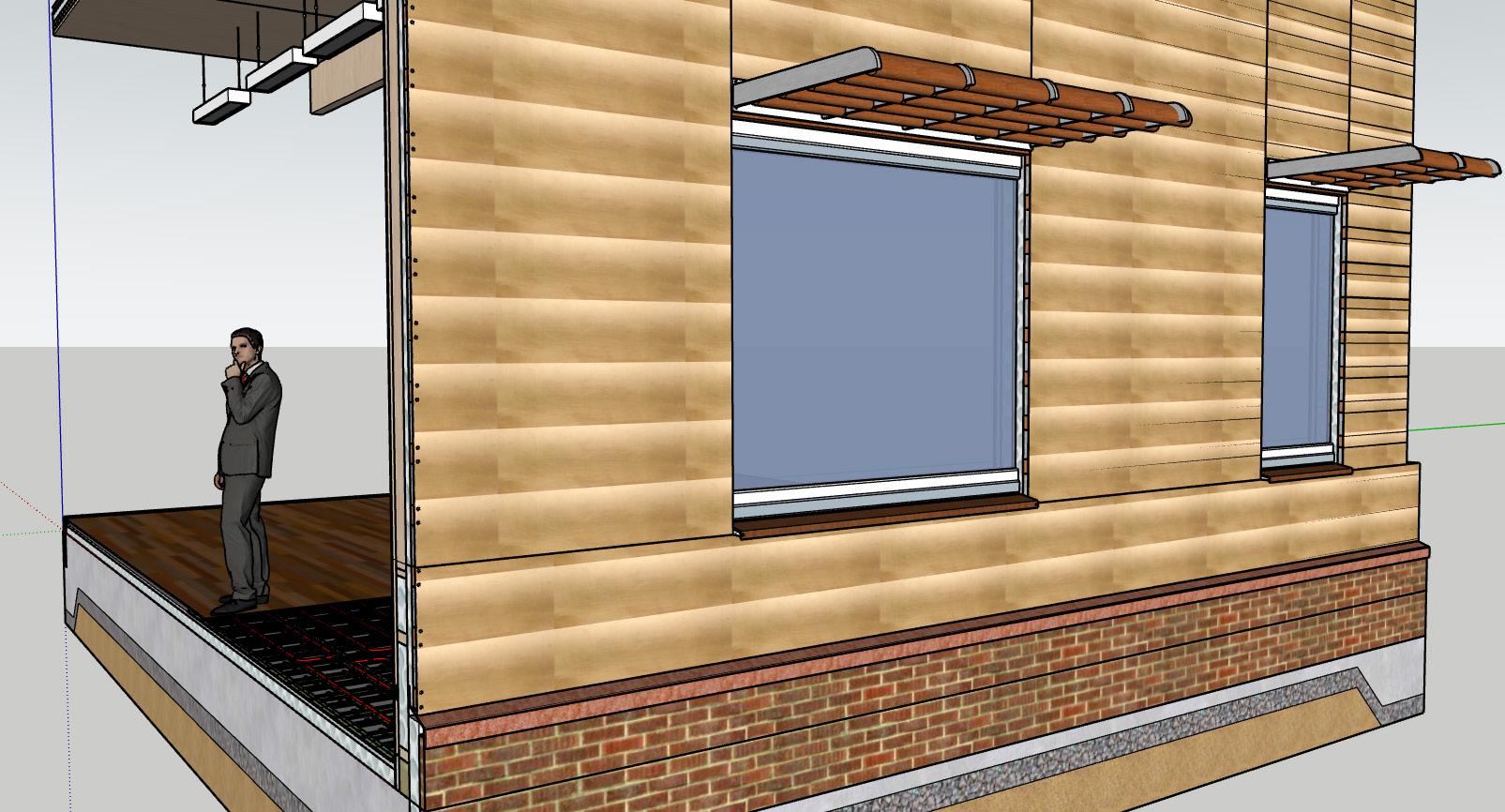
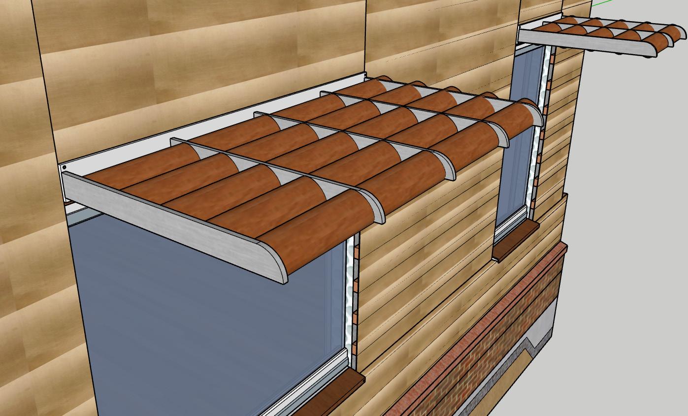
Fig 98. Windows with Flying Brise Soleil. Author's own work.
Fig 99. 1:10 Flying Brise Soleil in Detailed Section B-B. Author's own drawing.
Fig 100. Flying brise soleil 1000mm length with five Φ145mm elliptical blades. Author's own work.
Fig 101-104. Ventilation Diagram of Section B-B for Summer Day, Summer Night, Winter Day and Winter Night. Author's own drawings.
Fig 105-108. Ventilation Diagram of Section C-C for Summer Day, Summer Night, Winter Day and Winter Night.
Author's own drawings.
Fig 109-110. Axonometric pictures of Heating Pipes System. Author's own work.
Fig 111-112.Heating Pipes System location marked on ground and intermediate floor of 1:20 detailed section B-B.
Author's own work.
Fig 113-114.Axonometric pictures of Cooling Pipes System. Author's own work.
Fig 115-116. Cooling Pipes System location marked on intermediate and roof level of 1:20 detailed section B-B.
Author's own work.
Fig 117-118. Axonometric pictures of Ventilationn Duct System.
Author's own work.
Fig 119-120.Ventilation Duct System location marked on intermediate and roof level of 1:20 detailed section B-B.
Author's own work.
Fig 121-122. Axonometric pictures of Electrical Conduit System.
Author's own work.
Fig 123-125.Electrical Conduit System location marked on ground, intermediate and roof level of 1:20 detailed section B-B.
Author's own work.
Fig 126.Horizontal Travel Distances on ground floor.
Author's own work.
Fig 127.Travel distance requirements in Document B. Approved Document B,Fire Safety [online], (2022). gov.uk . [Viewed 14 May 2025]. Available from: https://assets.publishing.service.gov.uk/ media/67d17064a005e6f9841a1d50/Approved_Document_B_volume_2_Buildings_ other_than_Dwellings_2019_edition_incorporating_2020_2022_and_2025_ amendments_collated_with_2026_and_2029_amendments.pdf
Fig 128. Horizontal Travel Distances on first floor. Author's own work.
Fig 129. Horizontal Travel Distances on seocond floor. Author's own work.
Fig 130-132. Escape stairs requirements in Document B. Approved Document B,Fire Safety [online], (2022). gov.uk . [Viewed 14 May 2025]. Available from: https://assets.publishing.service.gov.uk/ media/67d17064a005e6f9841a1d50/Approved_Document_B_volume_2_Buildings_ other_than_Dwellings_2019_edition_incorporating_2020_2022_and_2025_ amendments_collated_with_2026_and_2029_amendments.pdf
Fig 133-135.Escape Stairs highlighted on plans.
Author's own work.
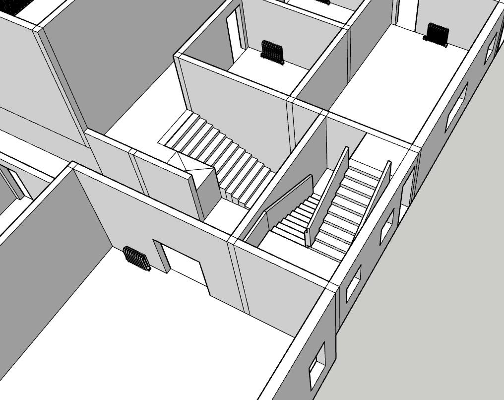
Fig 136-138.Escape Stairs locations marked in buildiing model. Author's own work.
Fig 139.Escape Stair 1 on ground floor.
Author's own drawing.
Fig 140.Escape Stair 2 on ground floor. Author's own drawing.
Fig 141-143. Exit Routes and Assembly Points of building on plans. Author's own drawings.
Fig 144.Escape routes and exits requirements in Document B. Approved Document B,Fire Safety [online], (2022). gov.uk. [Viewed 14 May 2025]. Available from: https:// assets.publishing.service.gov.uk/media/67d17064a005e6f9841a1d50/Approved_Document_B_volume_2_ Buildings_other_than_Dwellings_2019_edition_incorporating_2020_2022_and_2025_amendments_collated_ with_2026_and_2029_amendments.pdf
Fig 145.Ground Floor Plan showing car lanes, reserved emergency vehicle parkings, routes for firefighters to get into building and go upstairs. Author's own drawing.
Fig 146. Firefighting vehicles locations and entrances locations on building model. Author's own work.
Fig 147. Vehicle access routes requirements in Document B. Approved Document B,Fire Safety [online], (2022). gov.uk. [Viewed 14 May 2025]. Available from: https:// assets.publishing.service.gov.uk/media/67d17064a005e6f9841a1d50/Approved_Document_B_volume_2_ Buildings_other_than_Dwellings_2019_edition_incorporating_2020_2022_and_2025_amendments_collated_ with_2026_and_2029_amendments.pdf
Fig 148. Private hydrants requirements in Document B. Approved Document B,Fire Safety [online], (2022). gov.uk. [Viewed 14 May 2025]. Available from: https:// assets.publishing.service.gov.uk/media/67d17064a005e6f9841a1d50/Approved_Document_B_volume_2_ Buildings_other_than_Dwellings_2019_edition_incorporating_2020_2022_and_2025_amendments_collated_ with_2026_and_2029_amendments.pdf
Fig 149. Private hydrants locations on building model. Author's own work.
Fig 150.Private hydrants locations on ground floor plan. Author's own work.
Fig. 151. Building Structural Model. Author's own work.
Fig. 152. Building Model. Author's own work.
Fig. 153-154. Fire resistance requirements in document B. Approved Document B,Fire Safety [online], (2022). gov.uk. [Viewed 14 May 2025]. Available from: https:// assets.publishing.service.gov.uk/media/67d17064a005e6f9841a1d50/Approved_Document_B_volume_2_ Buildings_other_than_Dwellings_2019_edition_incorporating_2020_2022_and_2025_amendments_collated_ with_2026_and_2029_amendments.pdf
Fig. 155.Fire resisting requirements for different parts of building in document B. Approved Document B,Fire Safety [online], (2022). gov.uk. [Viewed 14 May 2025]. Available from: https:// assets.publishing.service.gov.uk/media/67d17064a005e6f9841a1d50/Approved_Document_B_volume_2_ Buildings_other_than_Dwellings_2019_edition_incorporating_2020_2022_and_2025_amendments_collated_ with_2026_and_2029_amendments.pdf
Fig. 156-157. Material details in structural bay model. Author's own work.
Fig. 158.1:50 Part Section B-B. Author's own drawing.
Fig. 159.Sprinkler systems in structural bay model. Author's own work.
Fig. 160-161. Sprinkler system mentioned in document B. Approved Document B,Fire Safety [online], (2022). gov.uk. [Viewed 14 May 2025]. Available from: https:// assets.publishing.service.gov.uk/media/67d17064a005e6f9841a1d50/Approved_Document_B_volume_2_ Buildings_other_than_Dwellings_2019_edition_incorporating_2020_2022_and_2025_amendments_collated_ with_2026_and_2029_amendments.pdf
Fig. 162-164. Compartmentation on plans. Author's own work.
Fig. 165.Compartmentation requirements in document B. Approved Document B,Fire Safety [online], (2022). gov.uk. [Viewed 14 May 2025]. Available from: https:// assets.publishing.service.gov.uk/media/67d17064a005e6f9841a1d50/Approved_Document_B_volume_2_ Buildings_other_than_Dwellings_2019_edition_incorporating_2020_2022_and_2025_amendments_collated_ with_2026_and_2029_amendments.pdf
Fig 166. West Section A-A having 6m-height event space,8m-height first floor roof , 9m-height second floor green roof.marked by warning signs. Author's own work.
Fig 167. South Section B-B having 5m-height art workshop,3m-height ground floor gren roof, 6m-height event space skylights, 3m-height ground floor cafe green roof marked by warning signs. Author's own work.
Fig 168. Boom Lift.
Civic Merchandising, (2024). The Flexible Reachability Solution: JLG Articulating Boom Lift [photograph]. [Viewed 15 May 2025]. Available from: https://civicmdsg.com.ph/heavy-equipment/lifting-equipment/boom-lifts/articulating/
Fig 169.Integratd Mobile scalffolding systems with Guardrails. Layher Limited, (2024). Advance Guardrail System [photograph]. [Viewed 15 May 2025]. Available from: https://www.layher.co.nz/scaffoldingsystems-equipment/accessories-system-free/advance-guardrail-system/
Fig 170. Integrated Anchor Points for Harness Systems. anchorsafe, (2025). Roof Anchor Points [photograph]. [Viewed 15 May 2025]. Available from: https://anchorsafe.com.au/products/roof-anchorpoint-systems/
Fig 171.Scissor Lift.
Adaptalift Group, (2025). 32ft / 10m Diesel Rough Terrain Scissor Lift Hire [photograph]. [Viewed 15 May 2025]. Available from: https://www. adaptalift.com.au/rental/32ft-10m-diesel-rough-terrain-scissor-lift-hire
Fig 172.Integrated safety harness system. erikafraga, (no date). S afety Harness | How To Ensure Safety Harness . [photograph].[Viewed 15 May 2025]. Available from: https:// www.bing.com/images/search?view=detailV2&ccid=OL5T8td%2F&id=1D4BEA3EC6C5A862CC12D6663EC89C59ECB7D0C8&thi d=OIP.OL5T8td_XTZeY1DUxZNtoAHaEc&mediaurl=https%3A%2F%2Finitiafy-website-images.s3.amazonaws.com%2Fwordpressupload%2F2014%2F04%2FHarness-safet-and-working-Warehouse-worker-with-safety-harness-secuerity-for-fall-protecti.png&exph=600&exp w=1000&q=Integrated+safety+harness+system&simid=608007992514842769&FORM=IRPRST&ck=CE404978C89F12CA8FECAAC850503 D62&selectedIndex=262&itb=0&cw=1375&ch=634&ajaxhist=0&ajaxserp=0
Fig 173. South Section B-B having wooden ramps at Ground Floor Community Garden marked by a warning sign.
Author's own drawing.
Fig 174. Anti-Slip Treatments for Ramp. adapta, (2022). Different Anti-Skid Options For Your Ramp [photograph]. [Viewed 15 May 2025]. Available from: https://adaptaramps.com.au/resources/different-anti-skid-options-foryour-ramp/
Fig 175. Drainage Systems for Ramp. Eurooppa, P., (no date). [Viewed 15 May 2025]. Available from: https://uk.pinterest.com/pin/Ab LemrsTFi2XnRQTwFyxZFPYwdBc8UoZDd_qnzyS0gCy4TrE_5xxCgI/
Fig 176. Handrails for Ramp. simplified building, (2025). How to Add ADA Railing to a Wooden Access Ramp [photograph]. [Viewed 15 May 2025]. Available from: https://www.simplifiedbuilding.com/projects/how-toadd-ada-railing-to-a-wooden-access-ramp
Fig 177. Warning Sign for Ramp. pdsigns, (2025). Caution Wheelchair Access Ramp Warning Sign [image]. [Viewed 15 May 2025]. Available from: https://www.pdsigns.ie/product/safety-disabled-access-and-parkingwarning-caution-wheelchair-access-ramp-sign/
Fig 178. South Section C-C having ground floor plant room marked by a warning sign. Author's own drawing.
Fig 179. Inspection Harch for Plant Room. Kiilax, (no date). Inspection Hatch with Push-Up Lock [photograph]. [Viewed 15 May 2025]. Available from: https://kiilax.fi/en/products/inspection-hatches/inspection-hatches/ispectionhatch-ptlms
Fig 180. Proper Seperation between Wet Zones and Electrical Equipment. Portakabin, (2025). Plant Rooms [photograph]. [Viewed 15 May 2025]. Available from: https:// www.portakabin.com/gb-en/solutions/other-building-uses/plant-rooms/
Fig 181.Grounding System for Plant Room. stationproject, (2013). grounding system [photograph]. [Viewed 15 May 2025]. Available from: https://stationproject.blog/wp-content/uploads/2013/10/grounding-system.jpg
Fig 182. Residual Current Device. ecsksa, (2023). The Importance of Residual Current Devices (RCD) in Electrical Safety [photograph]. [Viewed 15 May 2025]. Available from: https://ecsksa.com/blog/residual-currentdevice/
Fig 183. Waterseal for Plant Room. Waterseal Waterproofing, (2025). Plant Rooms and Service Decks [photograph]. [Viewed 15 May 2025]. Available from: https://waterseal.net.au/services/plant-rooms-and-service-decks/
Fig 184. 1:20 Detailed Section, Part Plan and Part Elevation.
Author's own drawing.
Fig 185-187. 1:20 Ground, Intermediate, Roof level sectiion. Author's own drawing.
Fig 188.1st and 2nd Stages of Construction. Author's own drawing.
Fig 189.3rd Stage of Construction. Author's own drawing.
Fig 190. Site Layout-Initial Site Analysis. Author's own work traced from Google Earth website contents.
Fig 191. Site Layout-Site Plan. Author's own work traced from Digimap Website contents.
Fig 192. Material Palette-Materials around the Site. Author's own photos combined with Digimap website contents.
Fig 193.Building Structure-Precedents for Structure from Field Trip.
Author's own photos.
Fig 194. Heating and Ventilation-Precedents for Heating and Ventilation.
Author's own work combined with Digimap website contents.
Fig 195.Fire and Life Safety-References for Relevant Firefighting Regulations.
Screenshots from Approved Document B:Approved Document B,Fire Safety [online], (2022). gov.uk. [Viewed 14 May 2025]. Available from: https://assets.publishing.service.gov.uk/ media/67d17064a005e6f9841a1d50/Approved_Document_B_ volume_2_Buildings_other_than_Dwellings_2019_edition_ incorporating_2020_2022_and_2025_amendments_collated_ with_2026_and_2029_amendments.pdf
Approved Document B,Fire Safety [online], (2022). gov.uk. [Viewed 14 May 2025]. Available from: https://assets.publishing.service.gov.uk/media/67d17064a005e6f9841a1d50/Approved_Document_B_volume_2_Buildings_other_than_Dwellings_2019_edition_ incorporating_2020_2022_and_2025_amendments_collated_with_2026_and_2029_amendments.pdf
Approved Document L, Conservation of fuel and power [online], (2021). gov.uk. [Viewed 14 May 2025]. Available from: https://assets.publishing.service.gov.uk/media/63d8edbde90e0773d8af2c98/Approved_Document_L__Conservation_of_fuel_and_power__ Volume_2_Buildings_other_than_dwellings__2021_edition_incorporating_2023_amendments.pdf
CDM 2015 [online], (no date). HSE. [Viewed 14 May 2025]. Available from: https://www.hse.gov.uk/construction/safetytopics/index.htm