Technology Brochure
WATTS is Astrimar's solution to integrate deflector base functionality into a simplified system for use with Neodrill’s CAN-ductor product, resulting in reduced cost and increased installation efficiency.
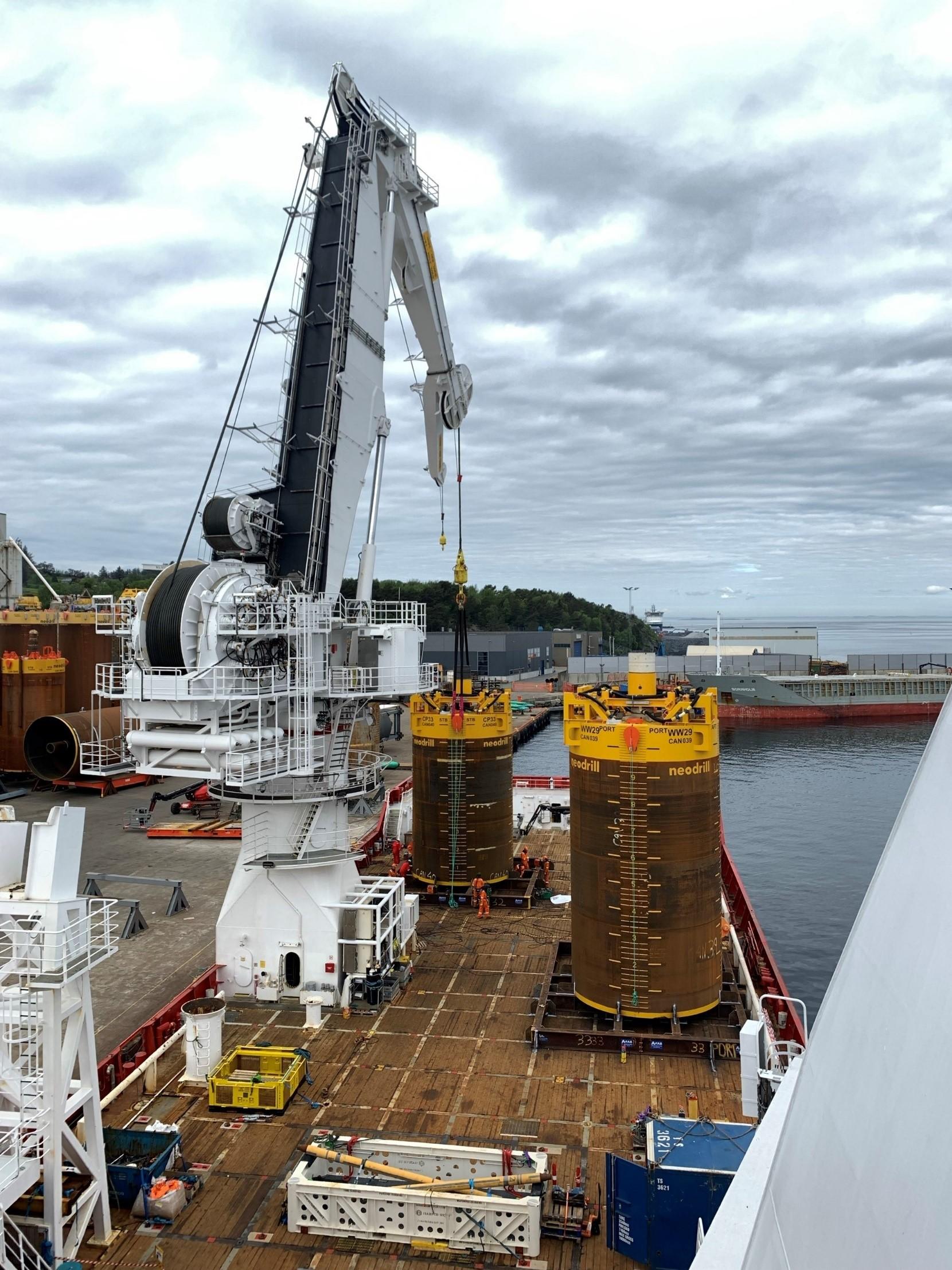
For a variety of future subsea wells, bp has elected to utilise the Neodrill (www.neodrill.com) CAN (Conductor Anchor Node)-ductor. This approach removes the need to carry out these operations from a Mobile Offshore Drilling Unit (MODU), instead enabling this to be done from a Subsea Construction Vessel (SCV). This in turn, significantly reduces installation time, costs, and carbon emissions. Note 1
A Deflector Base has historically been installed on top of the CAN-ductor. The Low-Pressure Housing (LPH) would then be installed through the Deflector Base and locked into position. bp engaged Astrimar to develop an alternative, simpler, and cheaper solution to a conventional Deflector Base design, which could be mounted on top of the CAN-ductor, utilising the available space. This alternative concept needed to provide the same system functionality as a conventional Deflector Base, but at much lower cost and with an improved tolerance stack up.
The concept was subsequently accepted by bp for detailed engineering, manufacture, testing, and subsea installation, initially on two new subsea wells. Through its development, the system has become known as: Wellhead Alignment and Torque Transfer System, or WATTS.
This document presents the key features and attributes of WATTS, as well as the developed and now proven assembly methodology.
Note 1: Further equipment integration functionality is possible with Neodrill CAN-ductor and Astrimar WATTS.

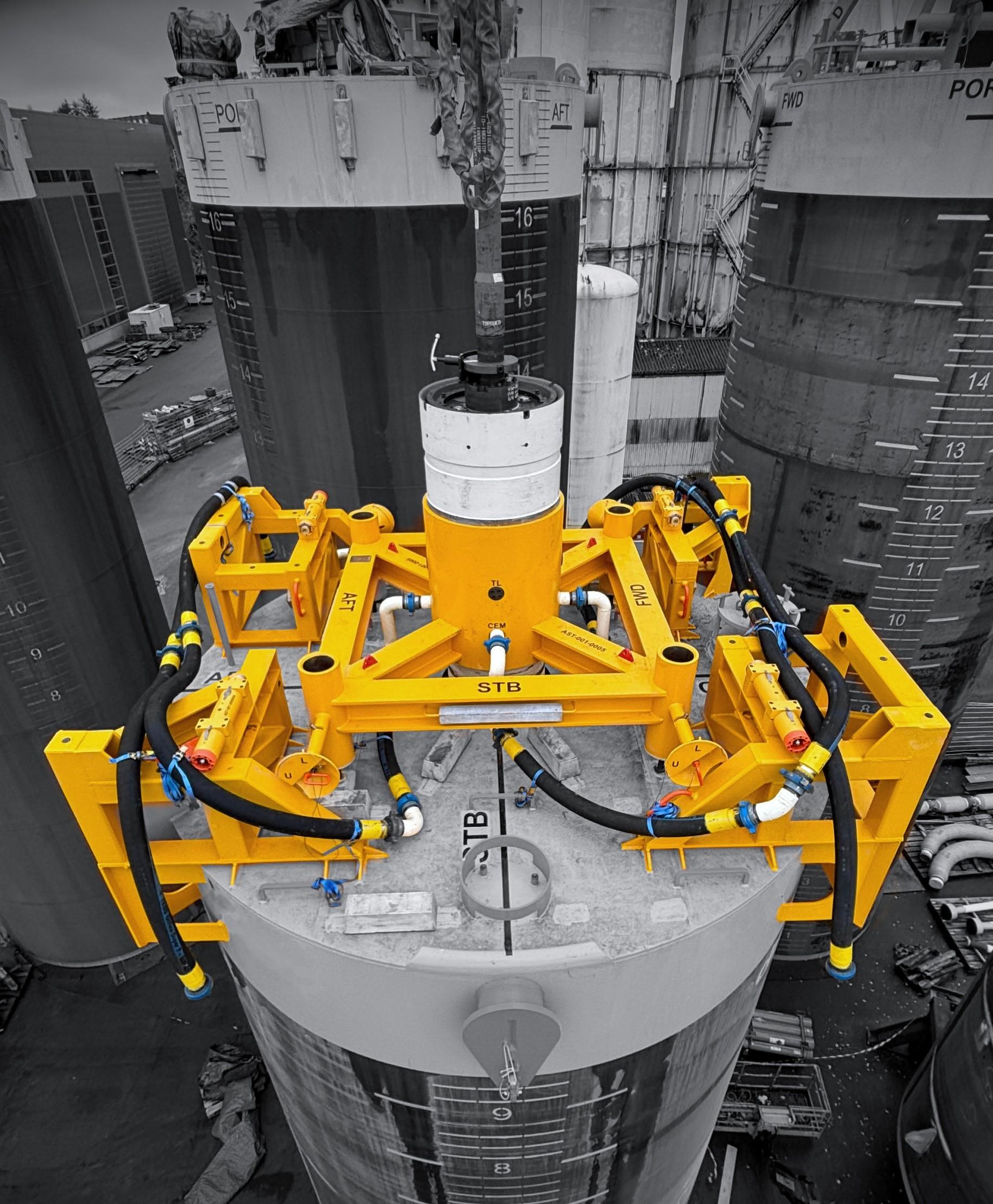
• WATTS provides effective interfacing with the outside of the Low Pressure Housing (LPH), locking into the cement ports.
• WATTS is fully assembled onshore and deployed together with the CANductor in a single operation.
• WATTS provides effective positioning and alignment of guideposts relative to the wellhead.
• WATTS provides snag-load torque-transmission functionality from XT/Flowbase into the CAN-ductor. Required capacity to resist fishing gear loads are in line with NORSOK U-101, Subsea Production Systems.
• WATTS transmits line-load and torque directly into the CAN, while the existing Deflector Base design transmits torque and line load to the LPH.
• WATTS Trawl-board and line-load snag resistance in line with NORSOK-U101.
• WATTS incorporates a trawler friendly design to reduce risk of snagging.
• WATTS provides ROV operable guidepost locking functionality.
• WATTS provides ROV docking functionality through integrated ISO13628-8 TDU interface.
• WATTS incorporates ROV grab-handles for functioning guidepost lockingpins and torque reaction pins.
• WATTS incorporates cement return lines from the LPH to the outside of the CAN-ductor envelope. Four hoses of 4” diameter.
• WATTS has minimal stiffening effect on the wellhead – hence no effect on wellhead fatigue life
• WATTS design life of 20 years (based on provided cathodic protection)
The first WATTS systems have been designed to work with a 38x36” wellhead, fitted with a standard 36” Supplementary Adaptor directly below the LPH.
• WATTS can be easily configured to interface with an alternative wellhead
WATTS provides numerous advantages over a conventional deflector base.
• Simplified design resulting in significantly reduced manufacturing costs compared to a conventional Deflector Base.
• Significantly reduced and simplified tolerance stack-up between the wellhead and guideposts, resulting in improved alignment accuracy.
• Snag loads are transmitted directly into the CAN-ductor due to the decoupled design of WATTS, bypassing the wellhead, resulting in improved system integrity and reliability.
• Modular design, enabling parallel manufacture and simplified onshore installation.
• Minimal effect on overall system stiffness with no change to the fatigue life of the wellhead system, due to the decoupled nature of the design.
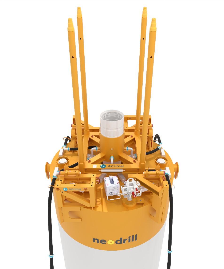
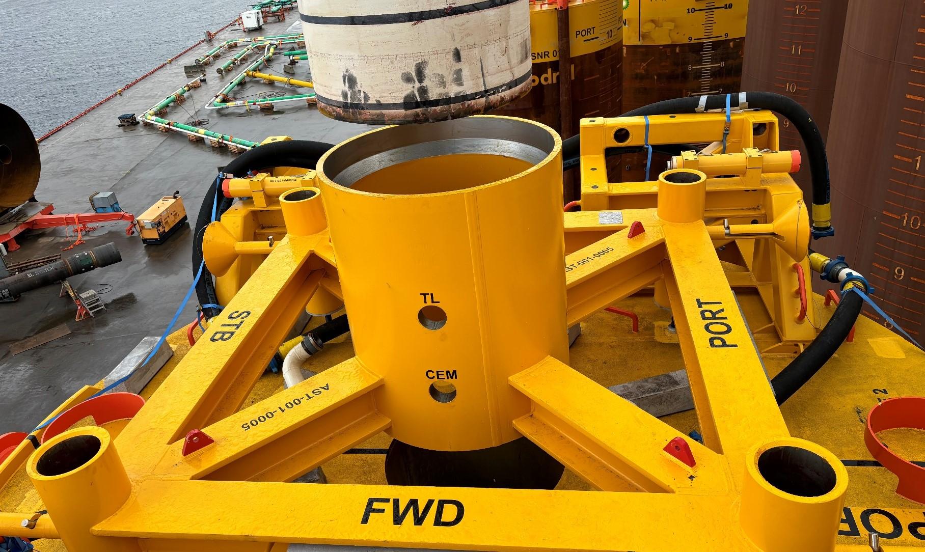
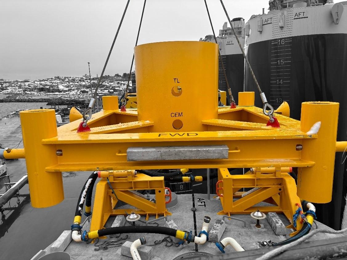
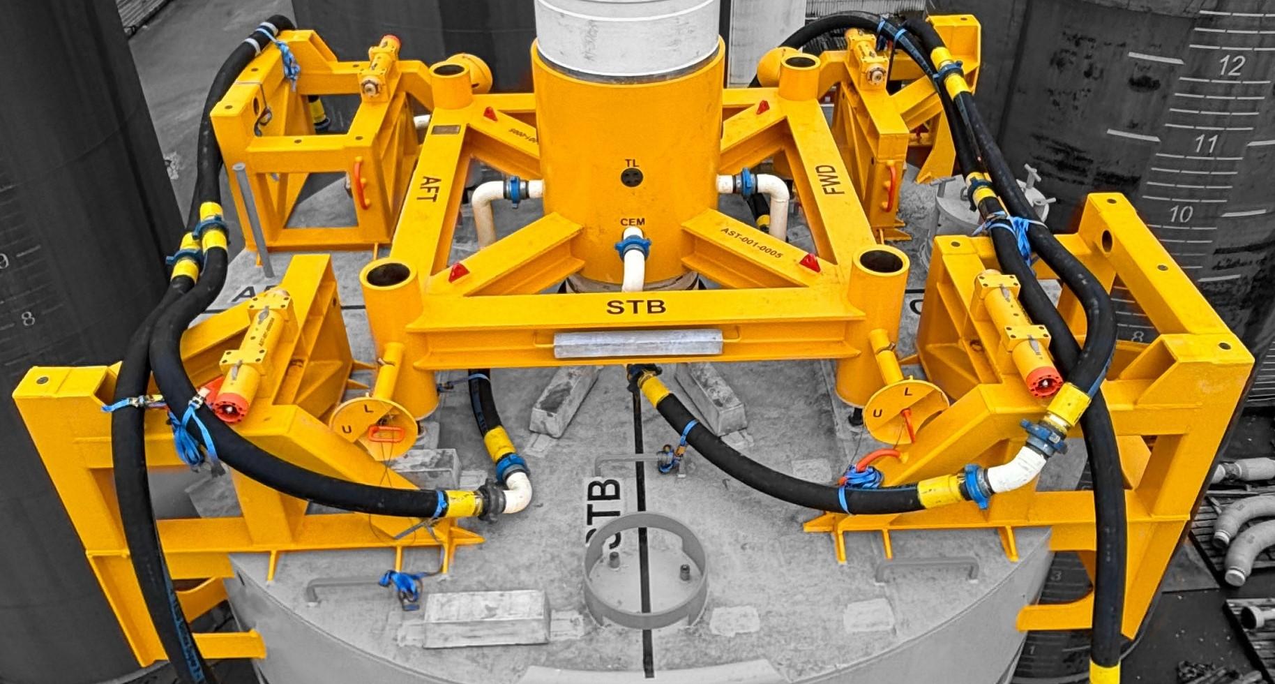
• CAF key function is to provide effective alignment between the LPH and the guideposts, located in the guidepost receptacles at the corners of the CAF, locked into place with ROV operable locking pins.
• CAF attaches directly to the LPH using four Taper-Lock assemblies.
• CAF’s machined landing-shoulder interfaces with the LPH taper profile.
• CAF incorporates two banks of machined ports.
o The upper ports use taper lock assemblies to lock the CAF to the LPH
o The lower ports provide access for the four cement spools screwed directly into the corresponding LPH threaded ports.
• CAF will not transmit snag load induced torque into the wellhead.
• CAF is welded, with precision machining of key interfaces conducted postweld.
• CAF incorporates sacrificial anodes sized for the full system design life.
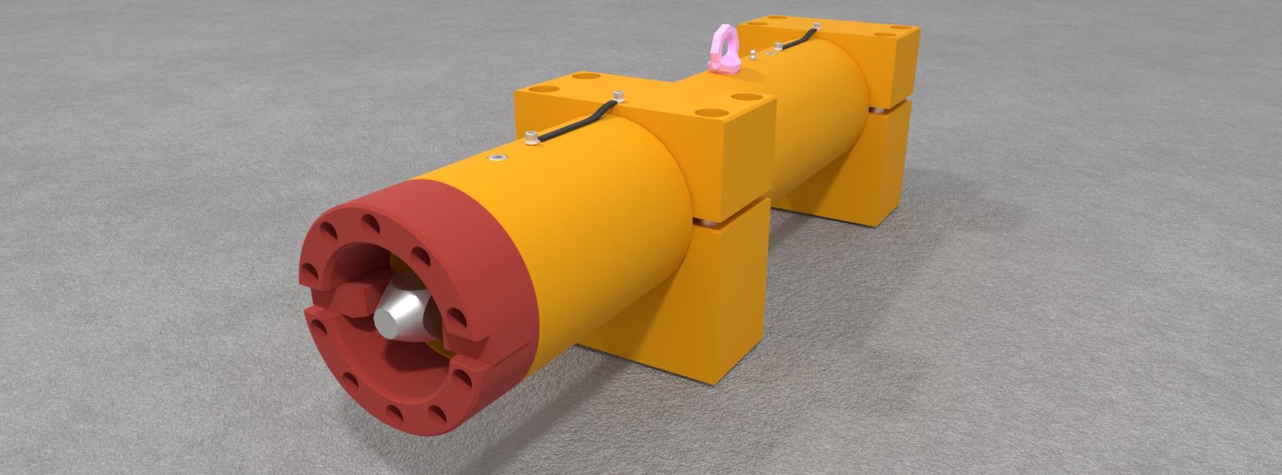
• Four TRPs (one per Corner Frame) are bolted to the Corner Frames for flexibility and ease of installation.
• TRPs react directly with the existing Flowbase torque reaction tabs.
• Snag load torque transmission is directly from the Flowbase, into the TRP’s, then into the Corner Frames and into the CAN-ductor.
• TRP assembly incorporates ISO13628-8 high-torque receptacle interface.
• TRP assembly accommodates system rotational misalignment up to 7°.
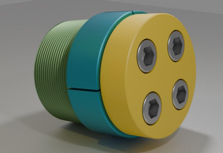
• Taper Lock Assemblies have been engineered to lock the CAF to the LPH.
• Four existing 4” tapped cement ports symmetrical around the LPH are used
• The inner part of the TLA is screwed and locked into the LPH tapped port.
• Outer taper lock segments are inserted into the TLA port on the CAF and locked into place.
• The system features four Ø4” cement return lines connected to the lower cement ports in the LPH adaptor via fabricated spools.
• The connections utilise WECO hammer unions.

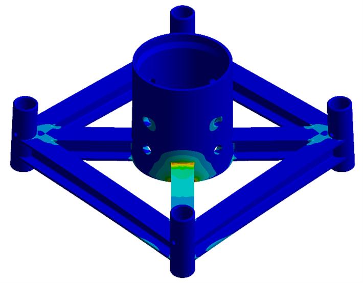
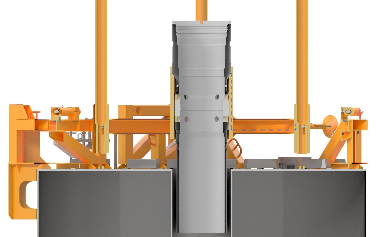
• Only the CAF contributes to the stack-up between the wellhead and the guidepost receptacles due to the simple design configuration and decoupled nature of WATTS.
• The design presents a very short tolerance stack-up path between the LPH landing shoulder, bore of the CAF and the guidepost receptacle sockets.
• The tolerance stack-up and potential misalignment is lower than that of a conventional deflector Base.
• The tolerance build-up path is indicated by the blue line in the figure below.
• Detailed tolerance stack-up calculations show the maximum predicted positional offset to be only 1.6 mm.
The key steps of the installation procedure are:
• Corner Frames are welded directly to the CAN-ductor top.
• Torque Reaction Pin assemblies are installed onto the Corner Frames.
• Pre-assembled cement lines are lifted into position.
• CAF jacking assemblies are installed.
• CAF lifted onto the CAN-ductor and lowered onto the jacks.
• LPH lifted vertically then lowered and landed on the CAF landing shoulder.
• Taper Lock Assemblies and Cement Spools would then be connected to the CAF and LPH.
• Dimensional survey
• The lower part of the LPH is welded to the base of the CAN-ductor.
• The cavity between LPH and CAN-ductor central bore is filled with cement.
• Jacking assemblies removed once cement has set.
• The system will be deployed from a construction vessel.

London area
Cranfield Innovation Centre
University Way
Cranfield
MK43 0BT
T +44 (0) 1467 620692
E info@astrimar.com
Aberdeen area
Lethenty Mill Business Centre
Lethenty Mill
Inverurie
AB51 0HQ
T +44 (0) 1467 620692 E info@astrimar.com www.astrimar.com