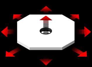
PORTFOLIO
LUOXIAN WU
EDUCATION BACKGROUND
Bangor University
2019/09-2022/06
Luoxian Wu
Product designer
About me
Name:Luoxian Wu
Date of birth:16/08/2000
Nationality:United Kingdom
Education:Master of Architectre
Fluent languages: English/Cantonese/ Mandarin
Contact
Email: Wuluoxian@hotmail.co.uk
Phone(UK):+447449588733
Phone(CN)+86 13302854553
BSc(hons) Product design First class degree with honour
University College London
2022/09-2024/01
WORK EXPERIANCE Professional
Morson Projects-Placement
MArch Design for Manufacture
Nefyn Sheds-Placement
2022/02-2022/07
During my time at Morson Projects I worked in the Part 21J DOA division. This division specialised in aircraft renovation, maintainence and airworthyness certification. My role was an intern design engineer working along side the design and engineering team generating designs from 2D sketched using Solidwork and running tests on the components before manufacturing and installation. Prior to the end of my placement I was offered a role as a freelance designer and worked on several NDA projects for the company.
Nefyn shed is a start up company located in North Wales. The company specialises in manufacturing summer houses, sheds and different wood products using timber. My role at the company was industrial and graphic designer where I promoted the company and developed a new line of design for the company.
Atelier One-Live project
2019/01-2019/08 2024-
skills
Atelier One is a well known structural engineering company based in London UK. Since graduation the company saw potential in my bamboo node design and offered resource and guidance to continue development of the node for a live project based in Tulum, Mexico. This project continued from The Arc at Green School Bali, Indonesia
Software knowledge Manufacturing knowledge
Rhino+Grasshopper
Fusion 360
Adobe suite
Solidworks Products Catia V5
Enscape
Keyshot 3D printing
Multi Axis CNC
Ceramic casting
Injection moulding
Merit
page
01. 02. 03. 04.
Content
Wifi enclosure SWA wire cutter Gwynedd Hub Bamboo node

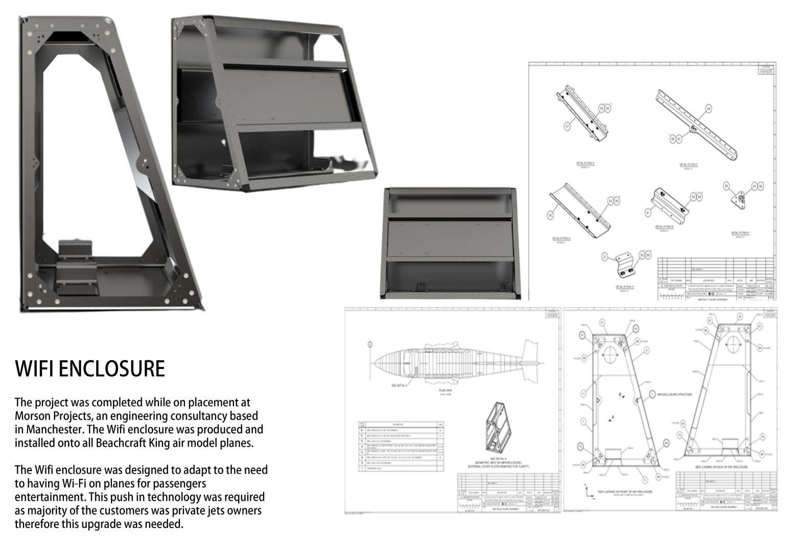
Wifi enclosure and USB hub
Project 1
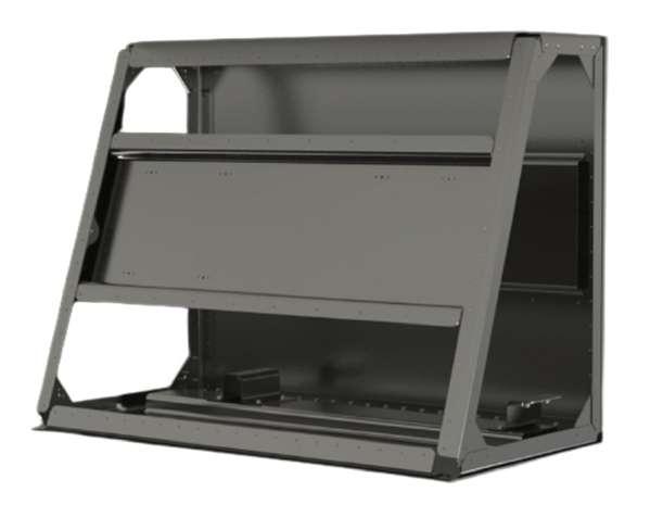
Wifi enclosesure for Beachcraft Kingsair
Project 2
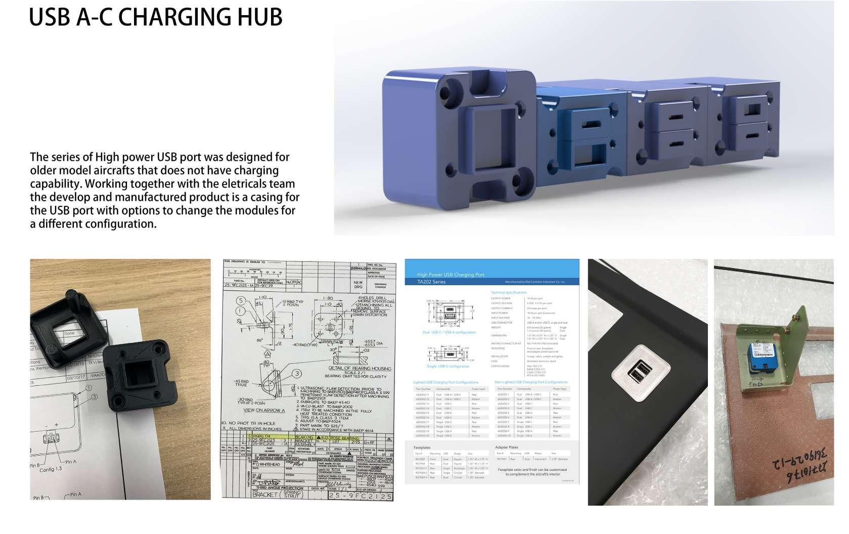
USB A-C Charging hub
01.
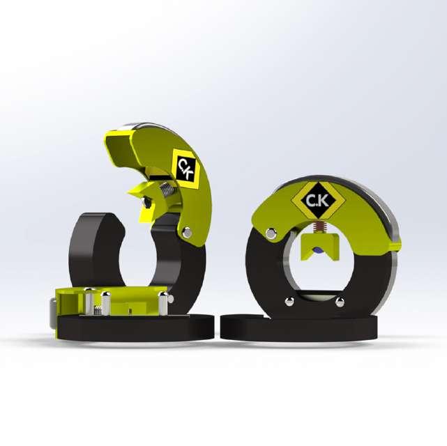

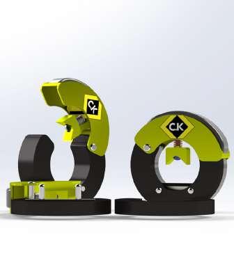
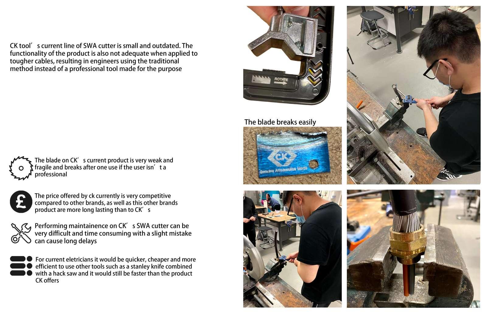
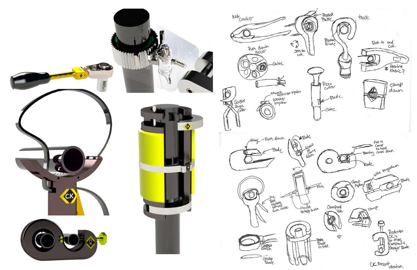
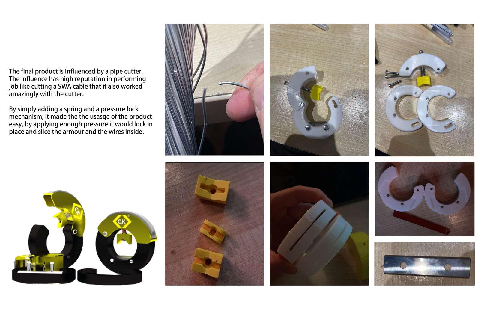
SWA wire cutter
SWA cable cutter for CK tools
02.
PROBLEM AND USER TRIAL
IDEATION
FINAL CONCEPT
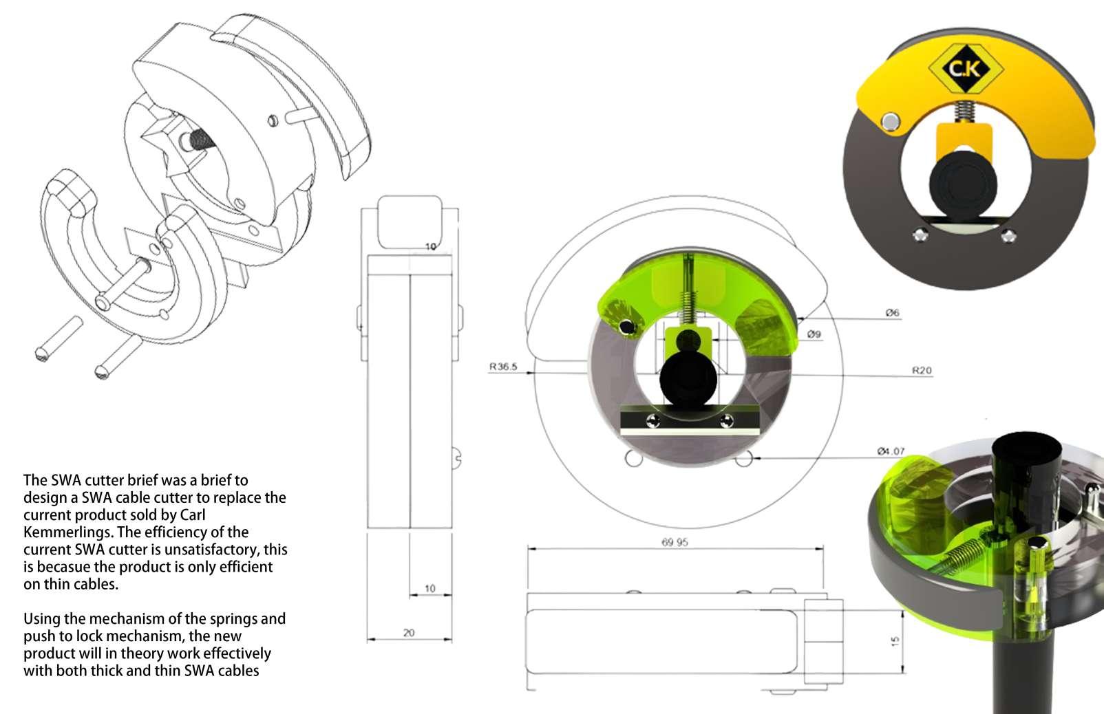
CONCEPT PROTOTYPE
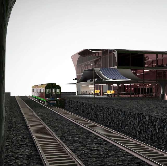

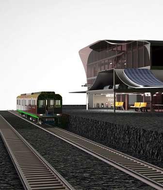
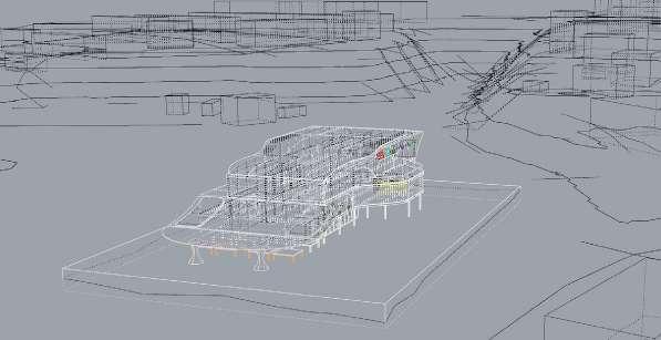
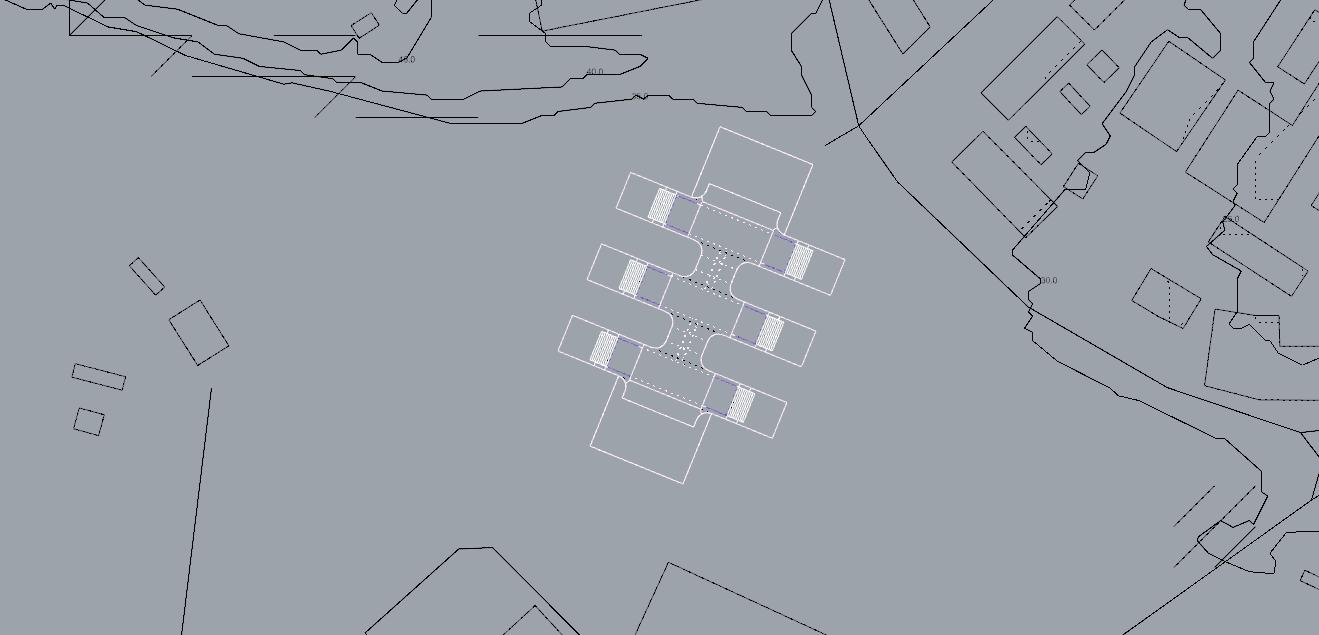
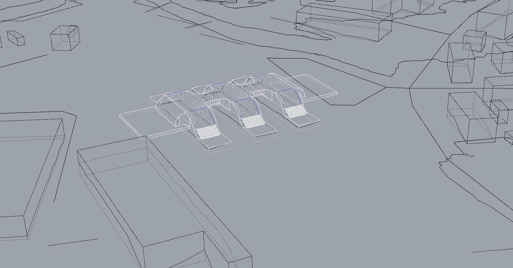
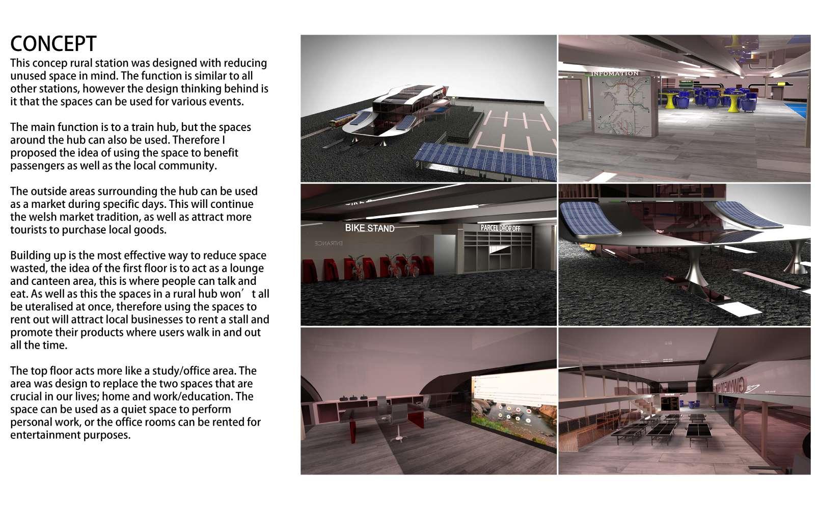
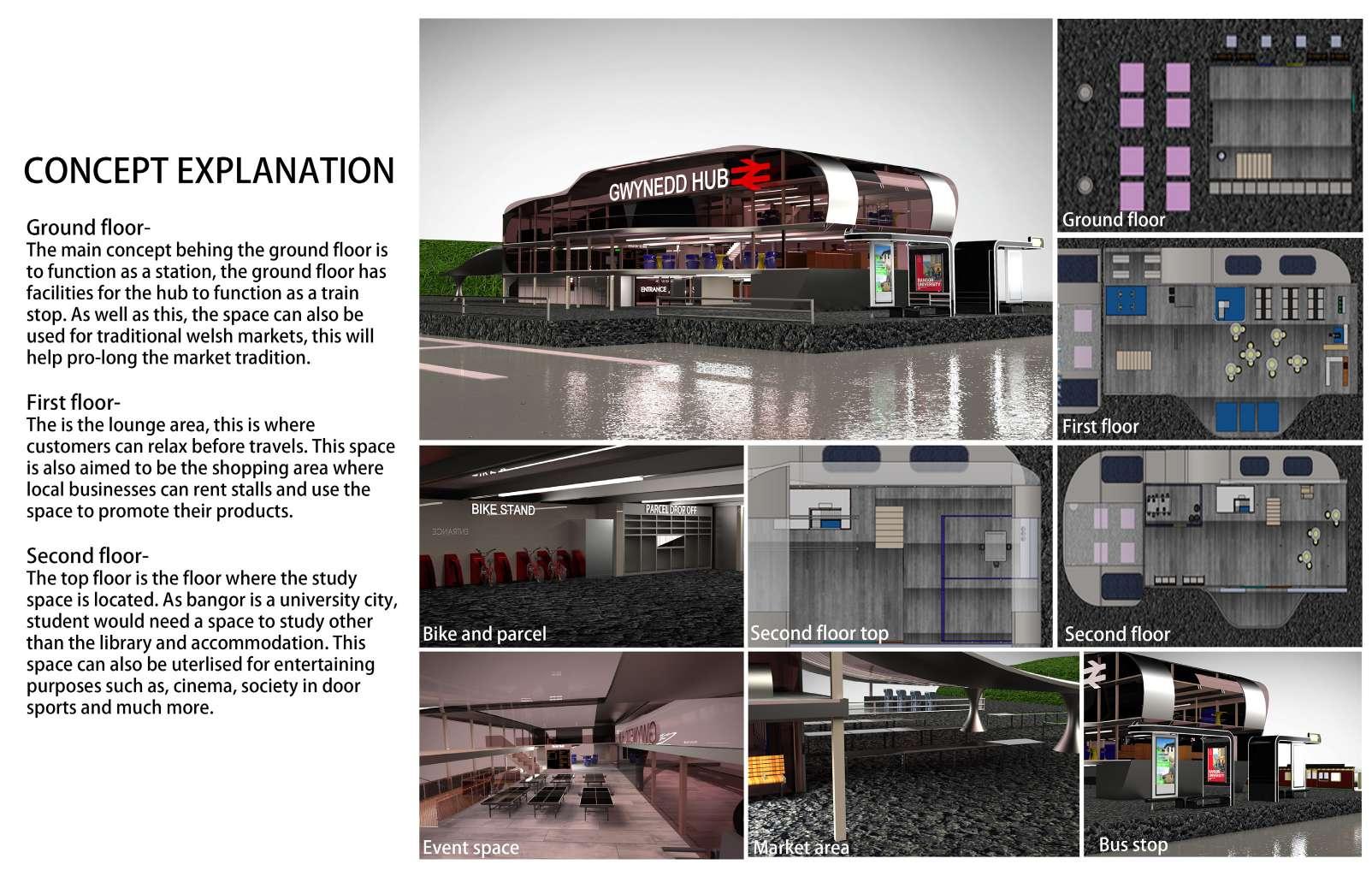
Conceptual train station for Network rails
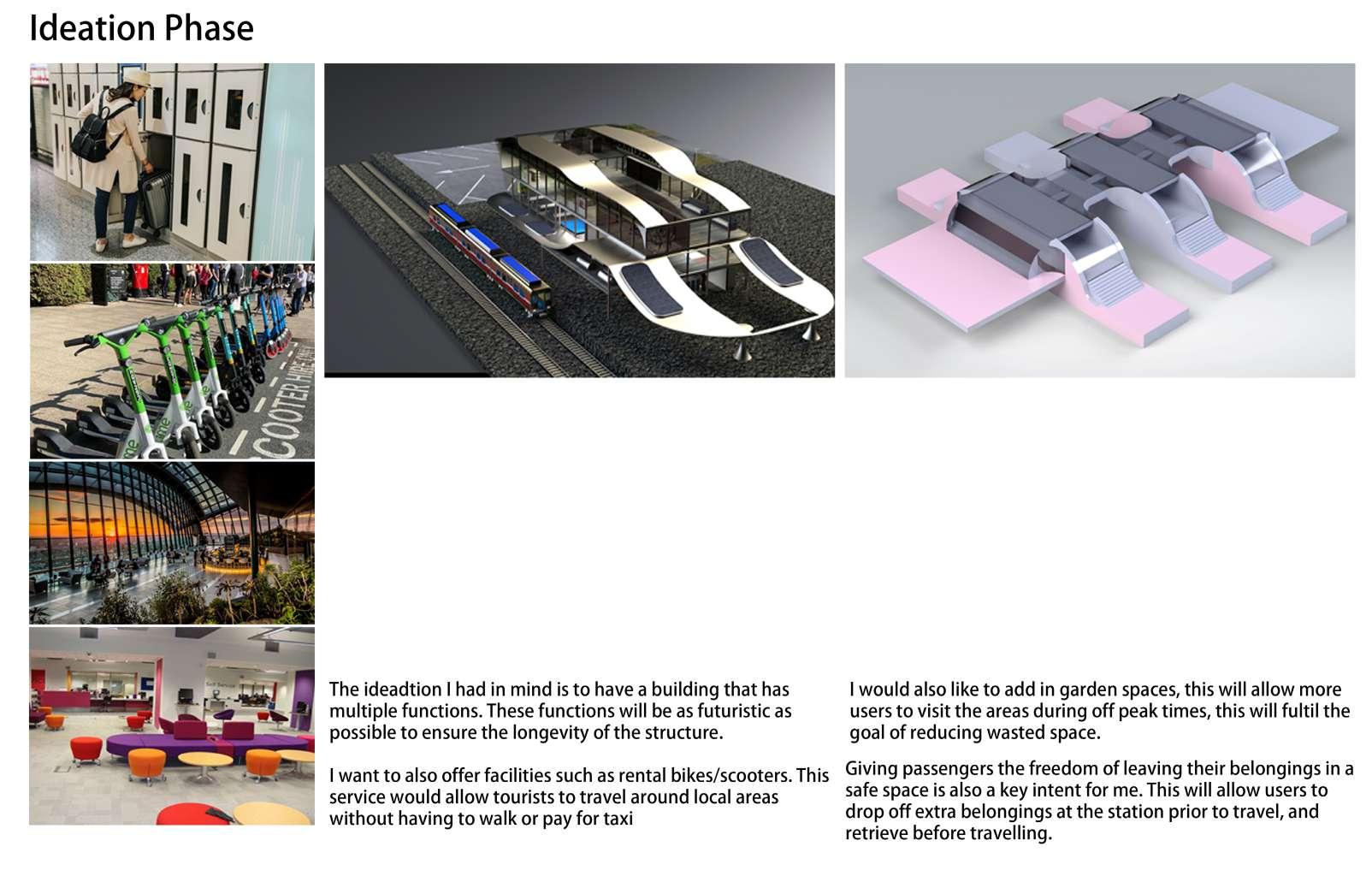
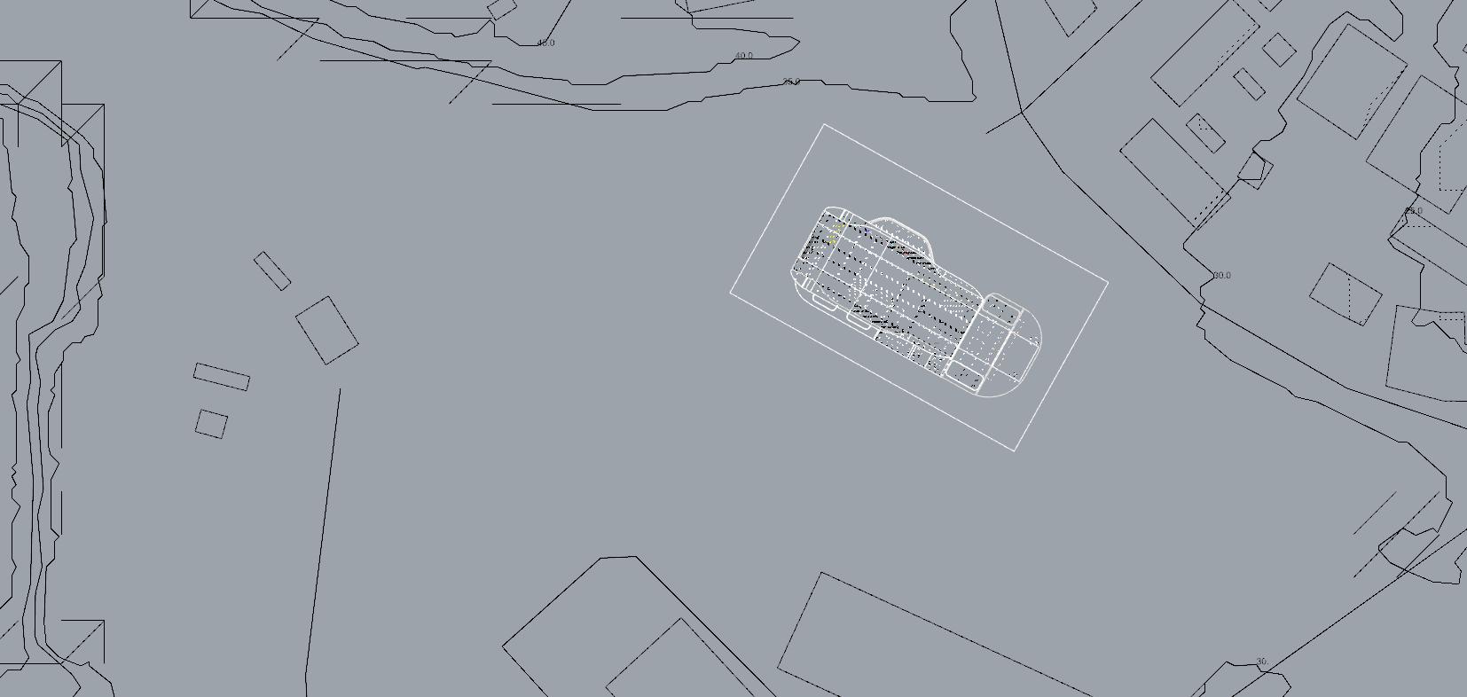
03. Gwynedd Hub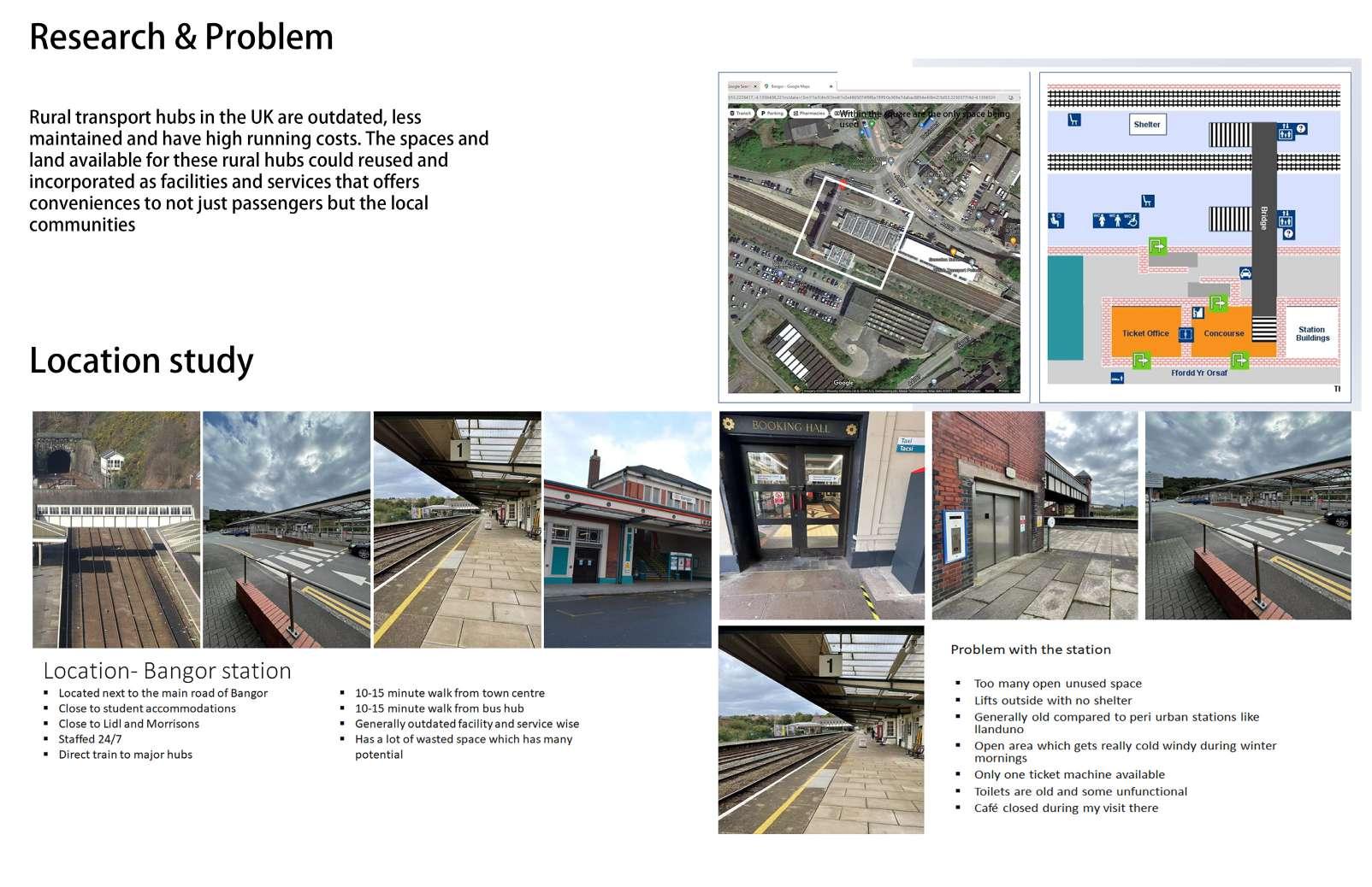
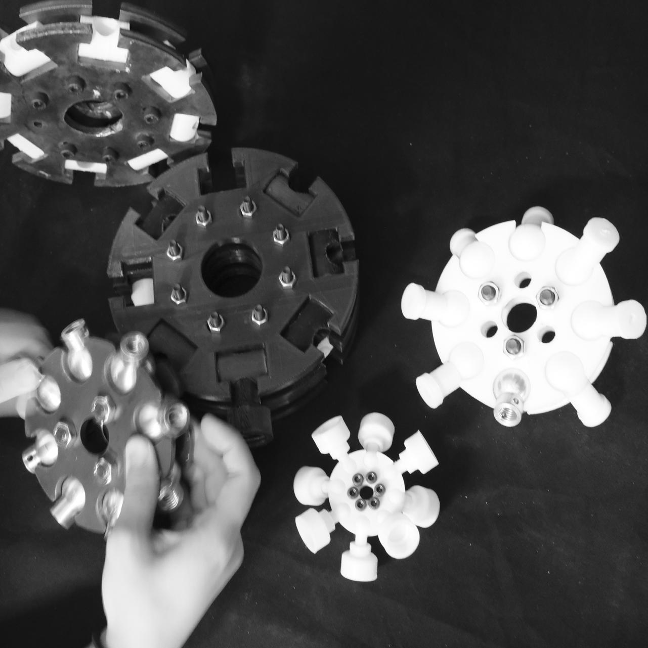
04. Adaptive bamboo structure
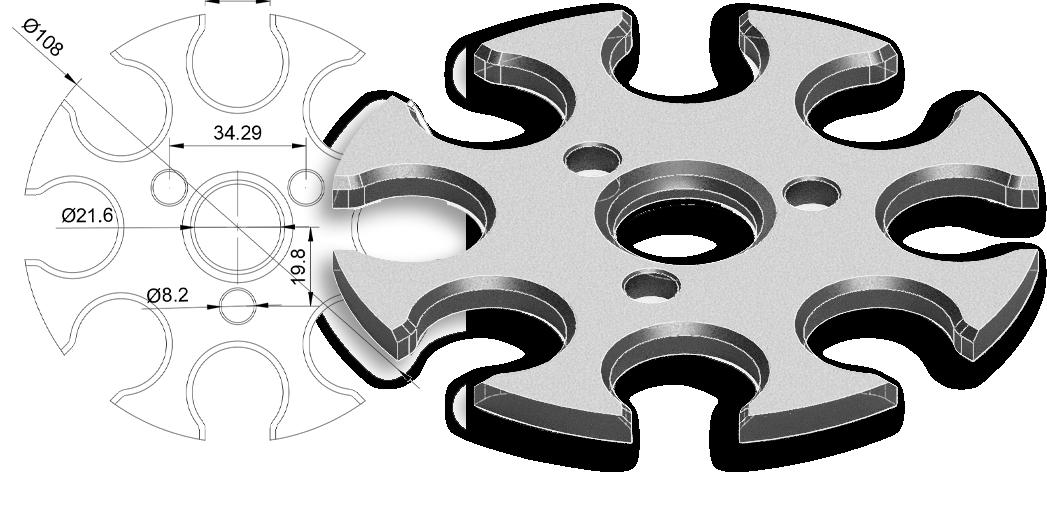
Modular component for bamboo
HUB Simplification
Design Strategy
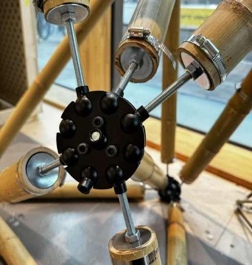
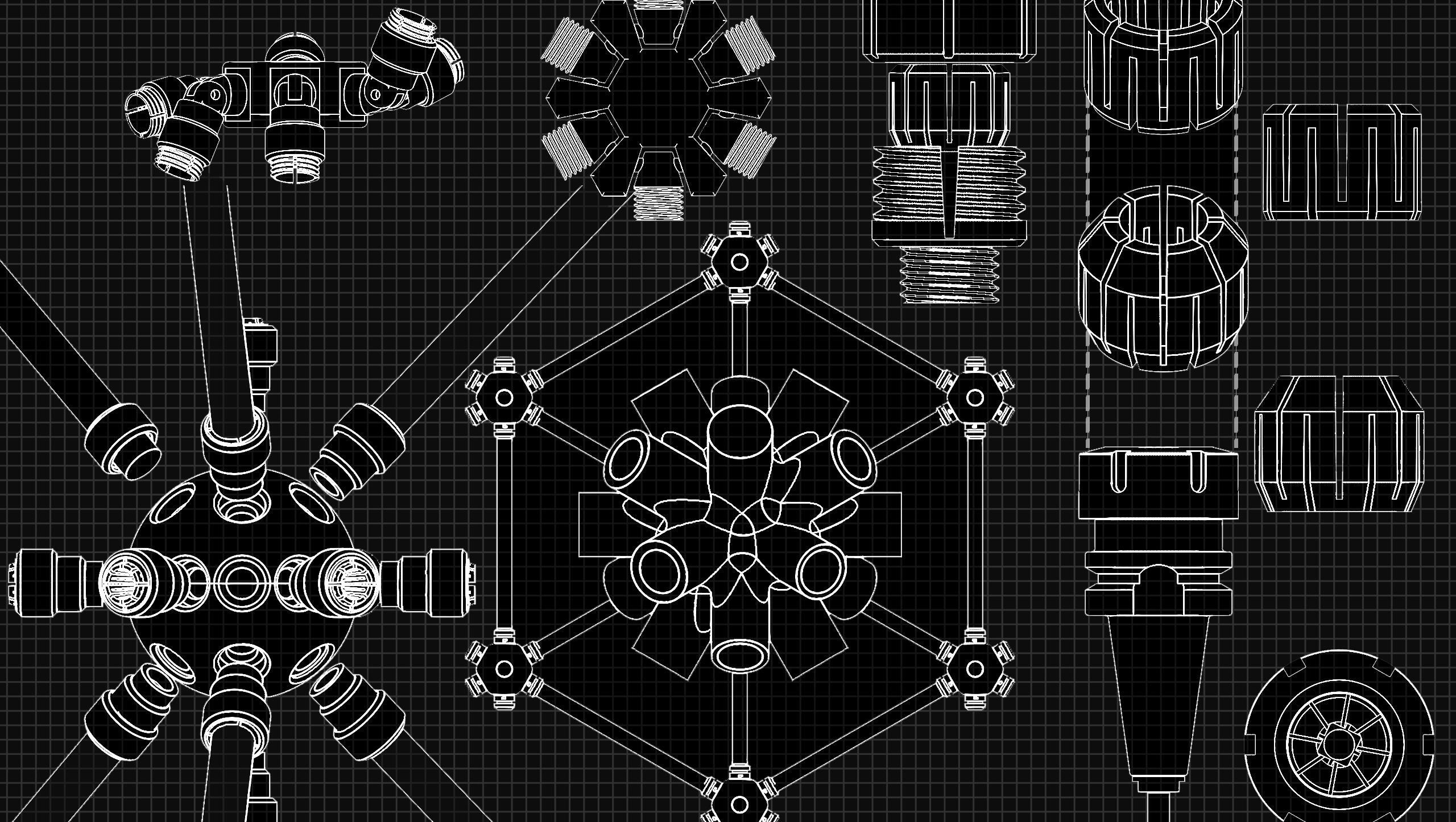
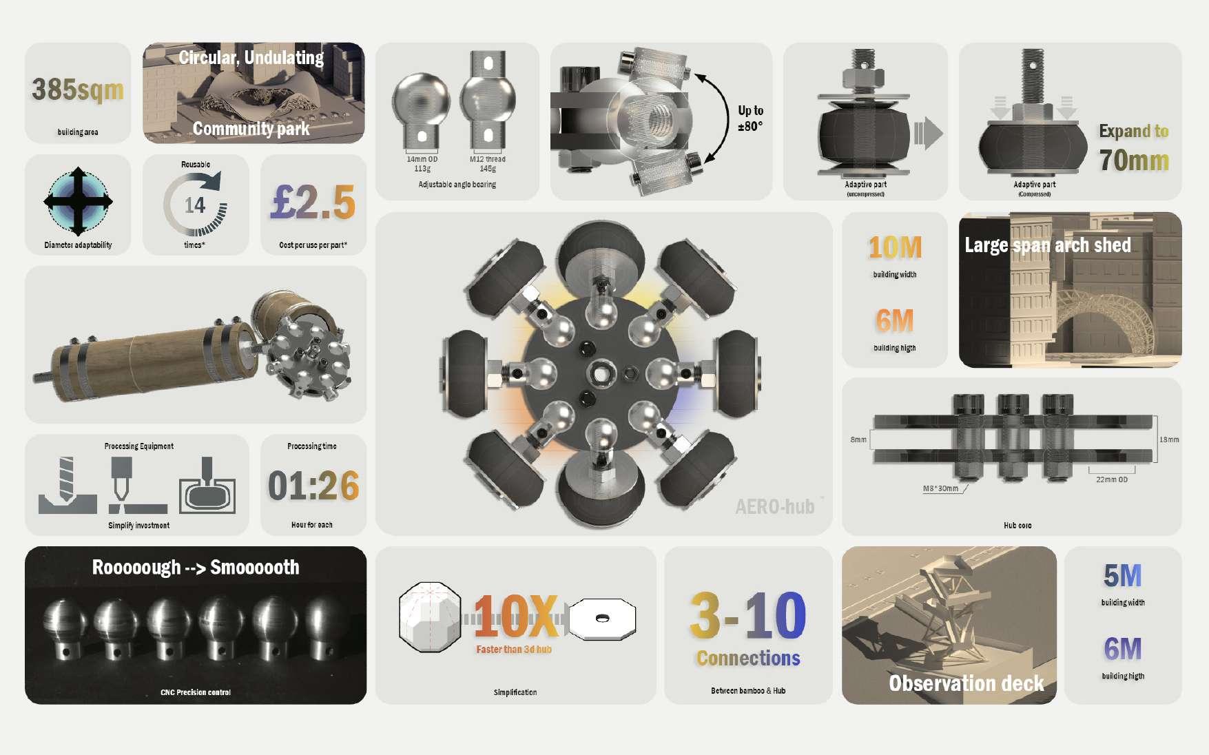
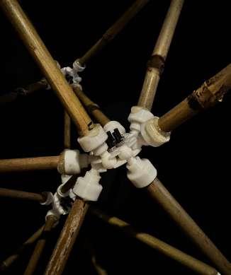
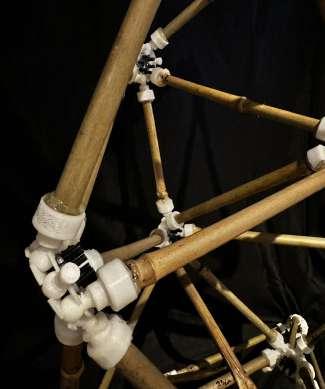
9 Axis Connection Chemical Fixed Architectural Modular Space frame Non-adjustable angle
Why research mero system?
■Mero's KK-SYSTEM demonstrates the connectivity capabilities required for space truss nodes. The use of Mero hub with its directional characteristics shows great potential in the use of hub system for bamboo space frame assemblies.
■At the same time, the processing complexity of the parts and standardized materials are the parts that need to be replaced by non-standardized materials in this solution.

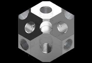
Outputs Abstraction
Simplification 13-Aixs 9-Aixs
Simplify Simplify
&
2D 9-Aixs
Building truss dome
Welding standard materials
Standardized truss nodes
Node design of bamboo structure
Design strategic
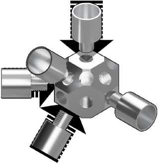
1.What are the basic requirements for a simplified version
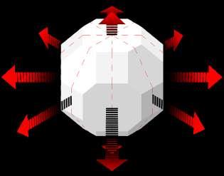
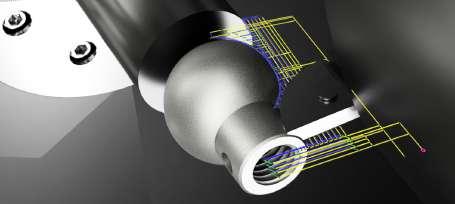
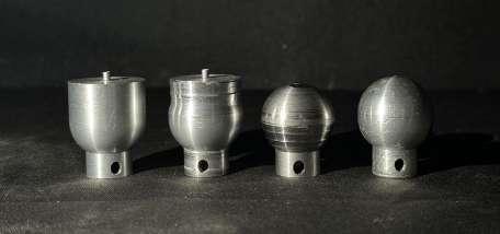
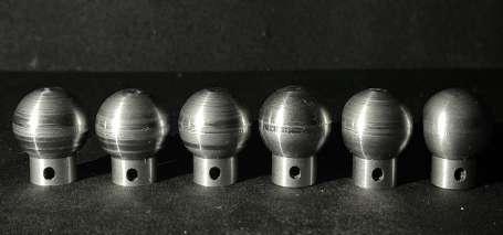
■The final design was based on the simplification of the Mero space hub, Through simplifying from 13 nodal directions to 9 nodal directions, the component still reached the maximum potential with options to sandwhich more component onto each other to generate more directions if required. From there the node design is then refined more to from a flat node to a spherical node that allwos flexible movement within the hub housing, which generated a smaller overall component.
2.Simplified approach to costs
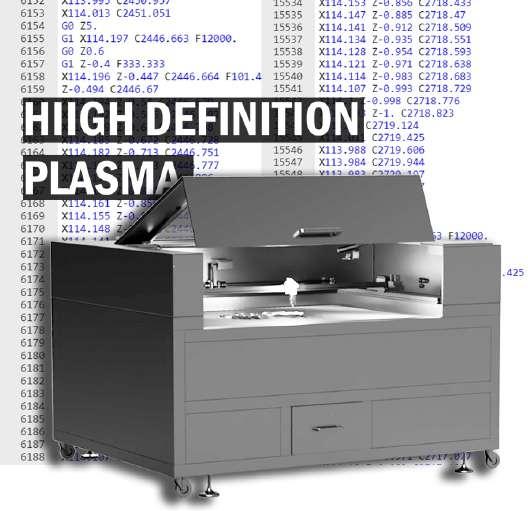
■The simpification resulted in a 2-dimentional component that houses the fuction of a 3- dimentional component, this simpification also lead to a cheaper manufacturing cost as the hub itself can be fabricated using high definition plasma technology which economically efficient compared to a 5-axis CNC machining. With the selection of steel over aluminium this also brung the price down but at the cost of weight, however when working in conjunction with bamboo this weight still performs better than steel tube.
Destination
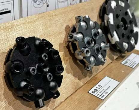
Ver 1.0 Ver 2.0 Ver 3.0 Total cost: Total cost: Total cost: £65 £40 £32 Weights: Weights: Weights: 1690g 680g 1150g
applicable:
applicable:
applicable: 9-axis connection 9-axis connection 9-axis connection
time
time
time Material: Material: Material: Steel sheet + Aluminum bar Steel sheet + Aluminum round bar Steel sheet & Steel round bar 03:15:00 01:45:00 01:45:00 Processing method: Processing method: Processing method: Plasma cutter + CNC Plasma cutter + CNC Plasma cutter + CNC
Maximum
Maximum
Maximum
Processing
Processing
Processing
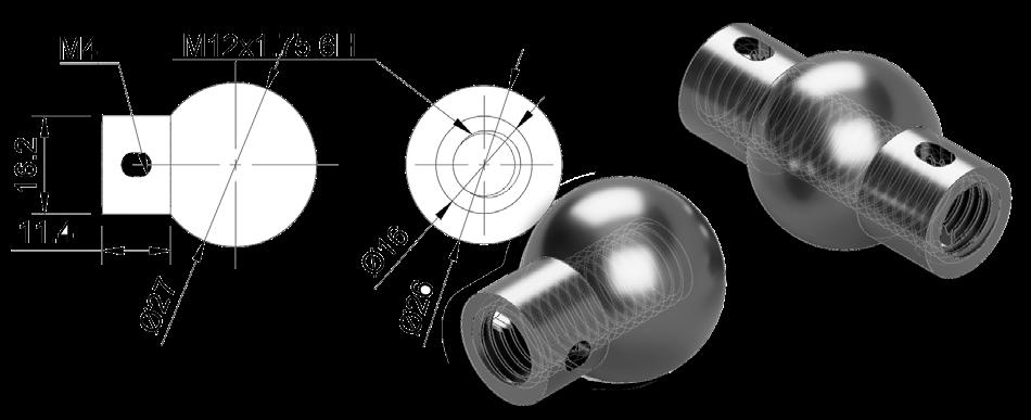
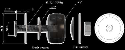
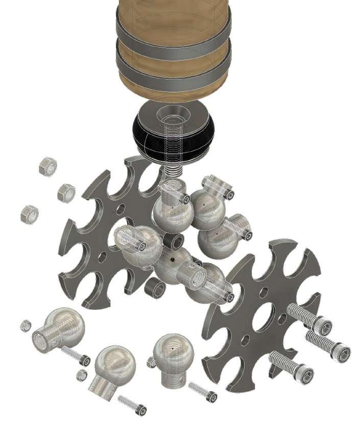

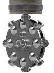
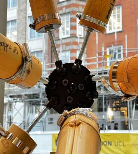
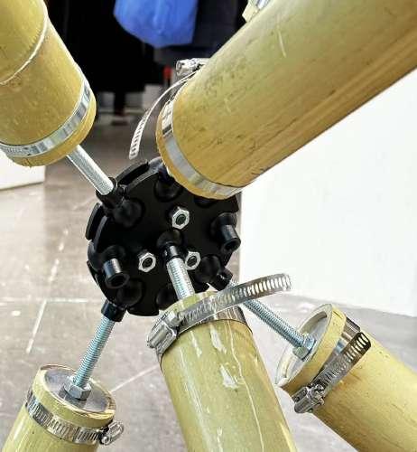
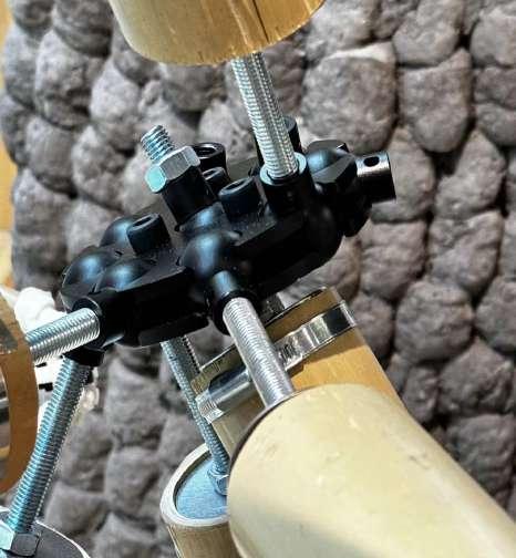
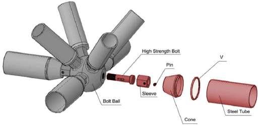
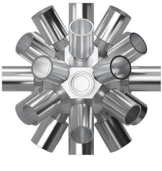
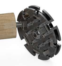
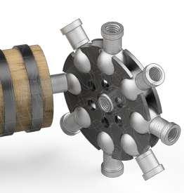
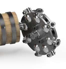
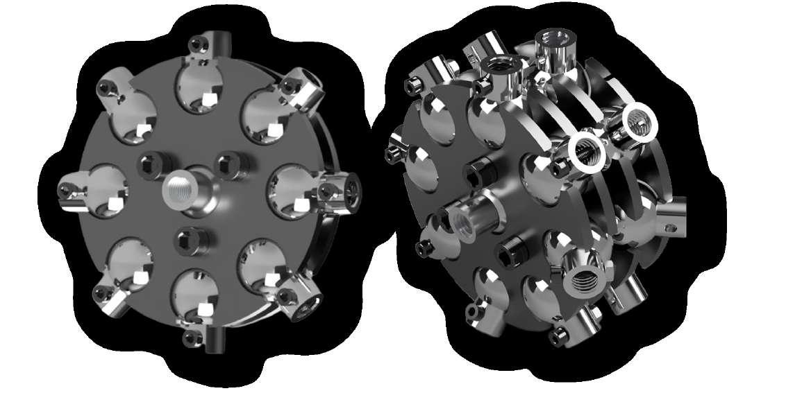
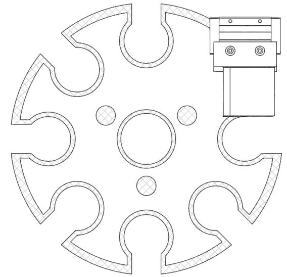
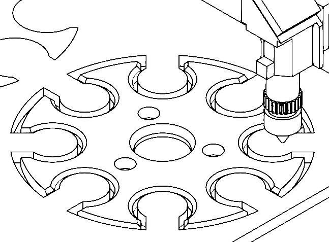
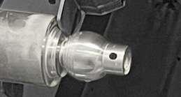
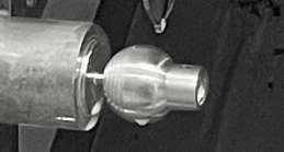
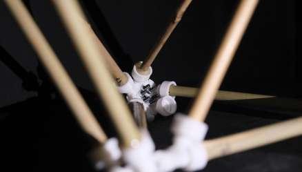
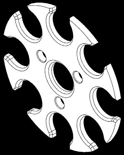
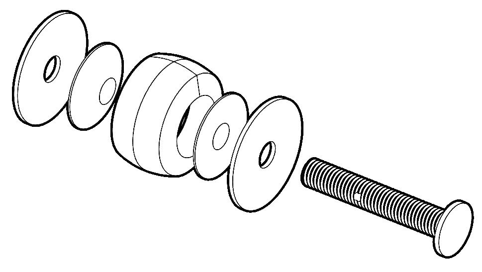
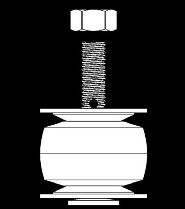
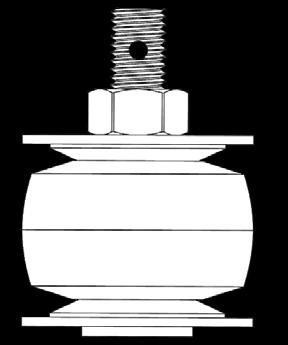
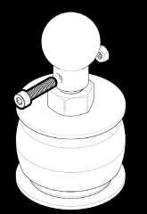
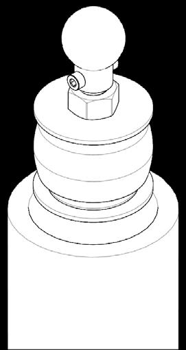
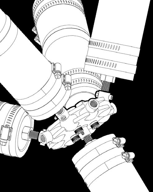
The Aero Hub, an innovative hub and node conceptual component meticulously crafted to harness the inherent strength and affordability of bamboo in both structural integrity and spatial formation. This unique design is a result of a meticulous development process focused on achieving simplicity and costeffectiveness. The fabrication process, driven by these key goals, has yielded a versatile, re-usable, reconfigurable, and adaptable component. Elevate your projects with the Aero Hub, a sustainable solution that seamlessly combines form and function.
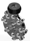
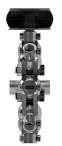
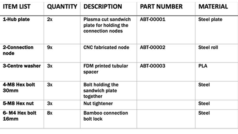
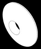
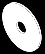
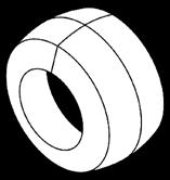
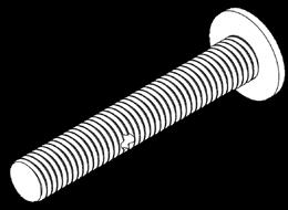
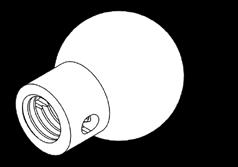
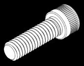
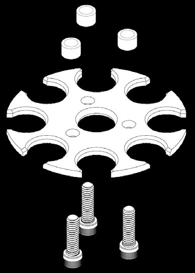
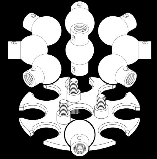
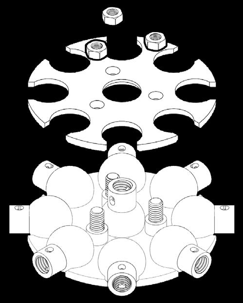
Bamboo 01:26:00 Bamboo Structure Hub Node Total processing time: Manufacturing method & material 5-axis CNC machining steel round bars 70° strength rubber injection Bamboo cutting by band saw Processing time: 00:06:00 Processing time: 00:18:00 Processing time: 00:00:30 Processing time: 00:00:30 Processing time: 00:00:20 Processing time: 00:05:00 Processing time: 00:08:00 Vertical drilling aluminium round bars Plasma cutting 5mm thick steel plate Pillar drill processing chamfering 5-axis CNC machining steel round bars Clip Screw threaded ferrule Expanded terminal M12 Threaded Slot Hub Splints Sphere connector M4 Socket head screw M4 Hex nut M8 Hex nut M8 Socket head screw Centre spindle 1-1 2-1 1-3 1-1 2-2 2-3 2-3 2-9 2-2 1-3 2-4 1-2 2-3 2-1 2-5 2-6 2-7 2-8 2-9 1-1 2-2 1-3 2-4 1-2 2-1 2-5 2-8 2-7 2-9 2-6 2-3 AERO-Hub Manufactural time:01:26:00 Component List Hub Node Expansion Hex m8 screw Bamboo B1.3 WEIJUN ZHU LUOXIAN WU Plasma cutter- Plates CNC-Node Injection moulding- Expansion rubber Expander Connector Hub Plate
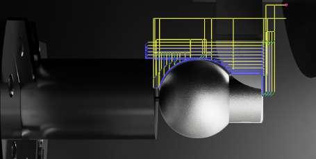
HUB diagram
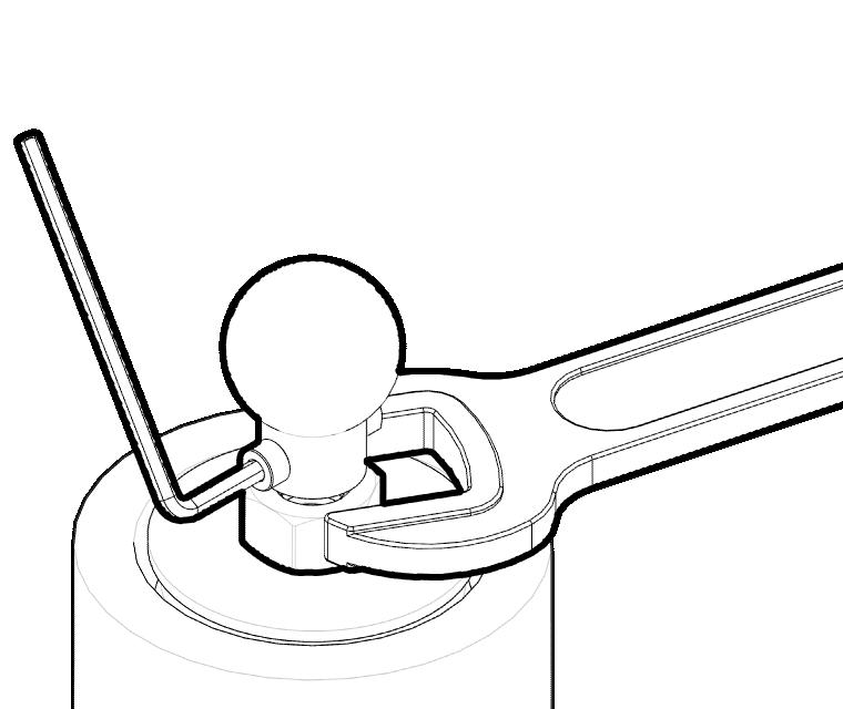
Assembly component list
■ Assembly of the final component requires 3x M8 threaded bolt partnered with 3x M8 threaded nut to sandwhich the two steel hub plate and 9x steel node together, partnered with 3x M8 threaded nut to assemble into the final hub. The hub evolved from a 3 dimentional concept into a 2 dimentional prototype which can be manufactured efficiently and cost effectively. At the same time having the potential to achieve the same function and form as the 3 dimentional concept.
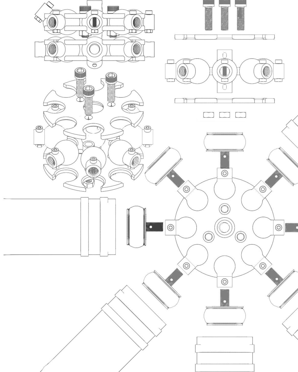
HUB
diagram
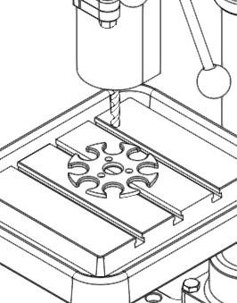
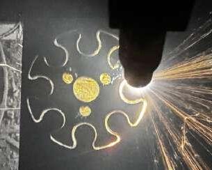
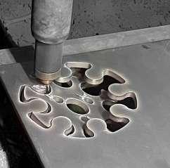
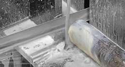
NODE fabrication - Plasma cutter Processing
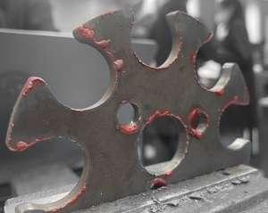
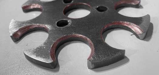
■The chosen mehtod of hub fabrication was using high definition plasma cutting technology. The use of plasma meant that the hub can be manufactured efficently and economically.
■Them sandwhich plate was fabricatied using steel sheet and plasma cutting technology. the process took less than a minute for a single plate. A single plate of steel (300x300) can cut up to 5 hubs
■After cutting the hub out from the plate, another process is required, inorder to have the nodes pivot freely, the node connection point must be champfered allowing more space to freely move. However if this is done by CNC it can be processed in one single machine operaion
Cutting perspective Pillar drill-
Cutting top view
Chamfing
1.
Plasma cutting
2.
Rough outcome
3.
Drilling-site
5. 4.
diagram
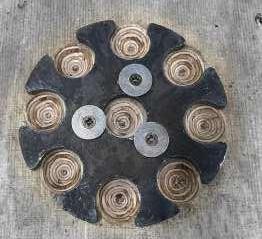
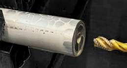
NODE fabrication - 5-Aixs CNC
■The most efficient method to manufacture the node was to CNC using a 5-axis CNC. This fabrication process is also the only process within this design that requires an expensive machine to produce the part. However it was neccessary as it is the most efficient method to manufacture the node.
Machining
40mm OD steel round bar cutting
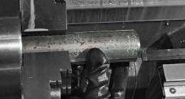
Facing operation

Drill and threading
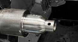
Cutting the node into shape
Parting tool were used to create the sphere
parting the node from the stock
Toolpath optimisation
Precision control
Step
Step
Step
Step
HUB
Step 1.
2.
3.
4.
5. Step 6.
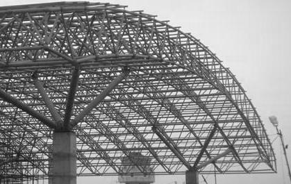
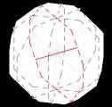
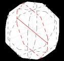
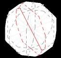
Space truss design
1.Force
analysis-Observation Tower
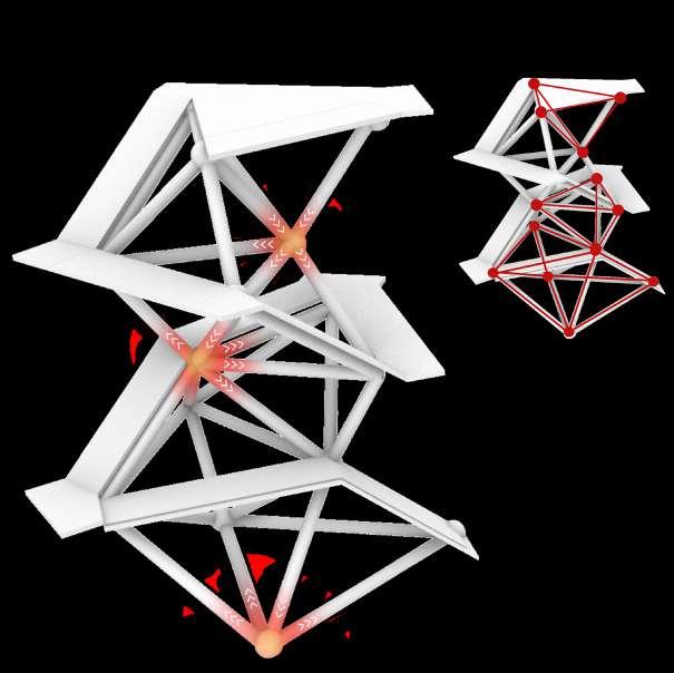
■ Using the theory of warren truss system of equilateral prism to generate a self standing structure where compress is formed at the top but released through out the structures system. This also follows the kuratowski’s and wagner’s theorems where even if the points were to move the structure would still be able to stand without issues

Compression begins to build up from the top of the structure. Top is where the pressure is situated.
As the pressure makes way downward the tension is released through the prismatic structure.
The tension release continues as it makes it way downward to the bottom where its fully released.
The tension is fully released at the bottom of the structure where the energy is released into the foundation.

1
2
3
4
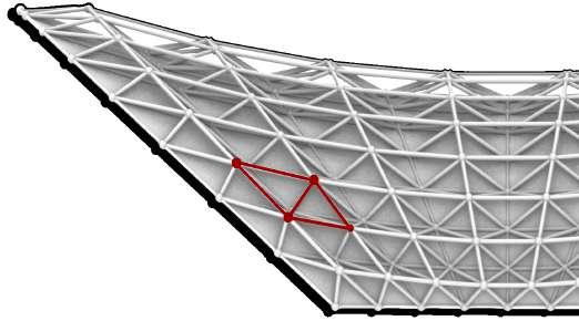
Space truss design
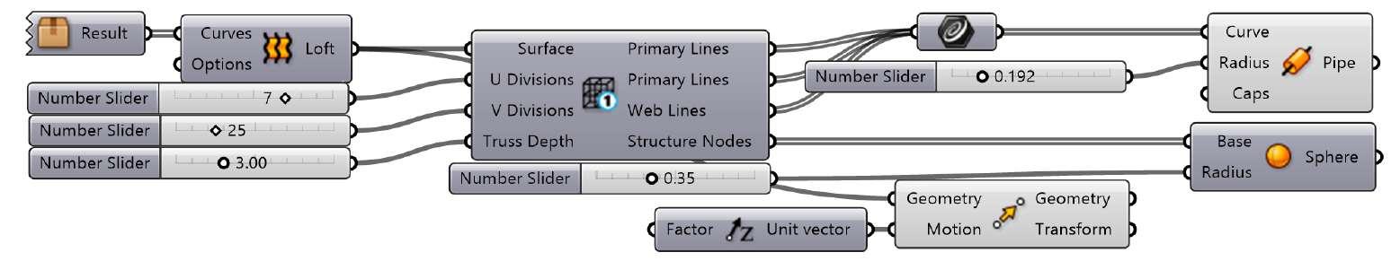
2.Structure generation-Undulating roof
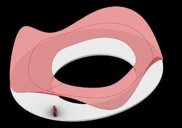
1.Set up surface
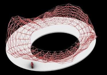
2.Generate Truss system
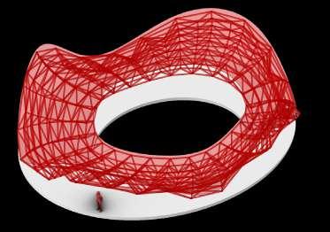
3.Adjust part size
Lofting the surface to generating the overall pavillion shape.
Space truss structure code fransfers the lofted surface to lined forming the shape of the pavilliobn in points and lines format.
Join curve joins the Z axis line and X axis line together to form the outer frame
■ Testing the pipe and node to simulate the hub and bamboo joint and where location of both node and hub. At the same time this can also show the lengths that the bamboo needs to be in preparation toward the possible model assemblies.

Selected attempt
2.Aim of design
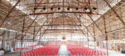
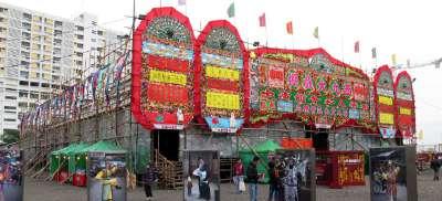
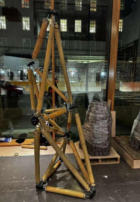
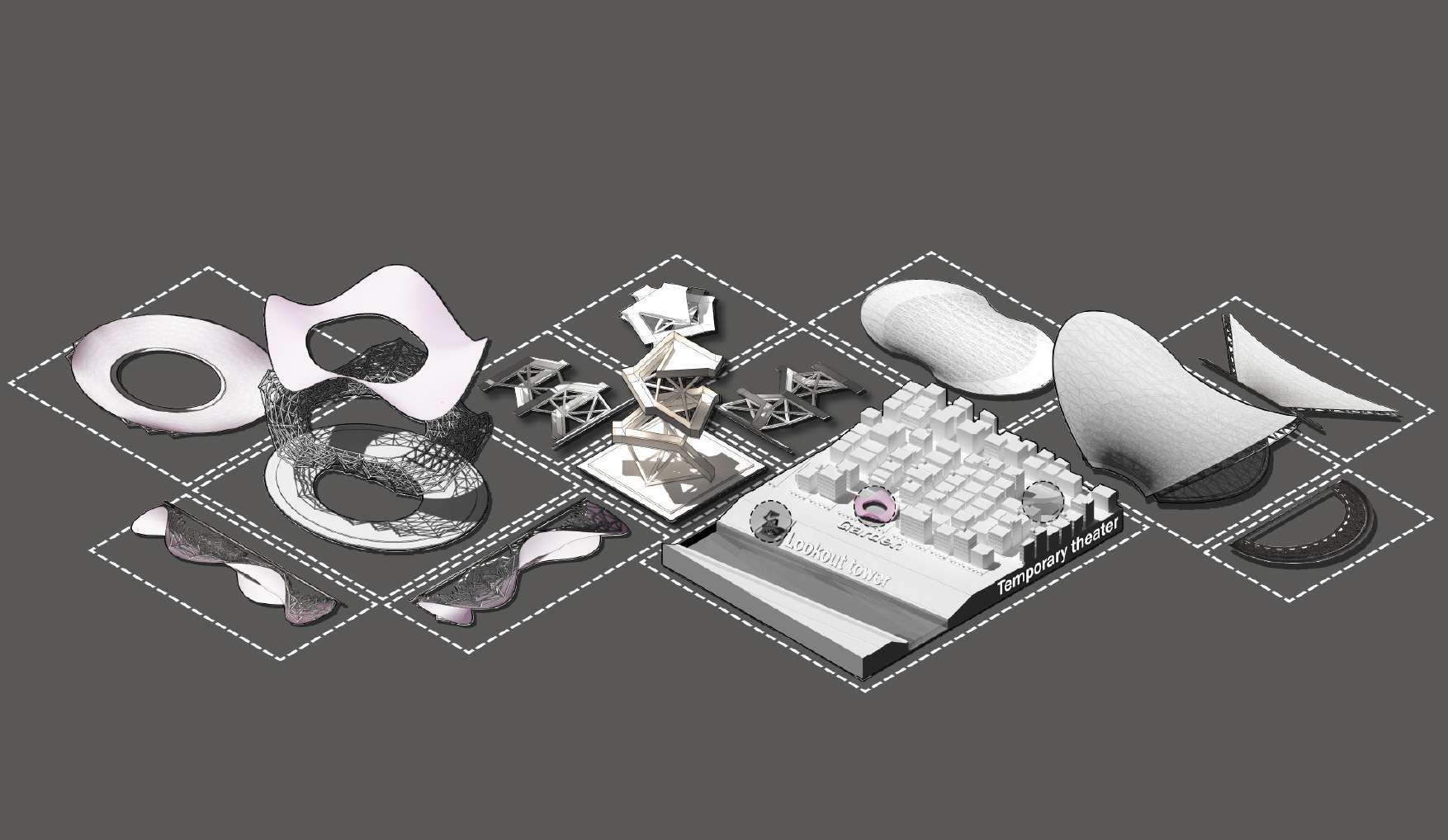
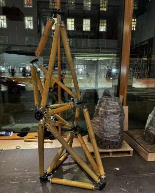
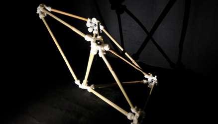
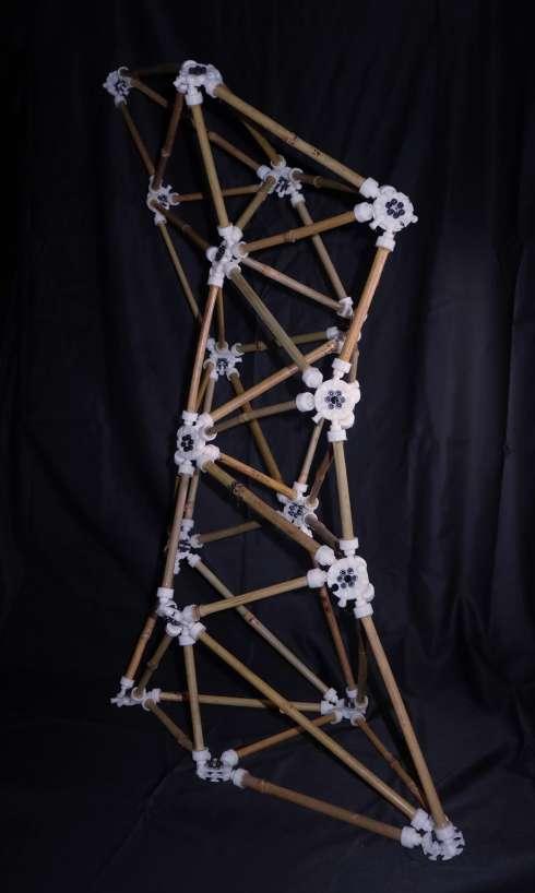
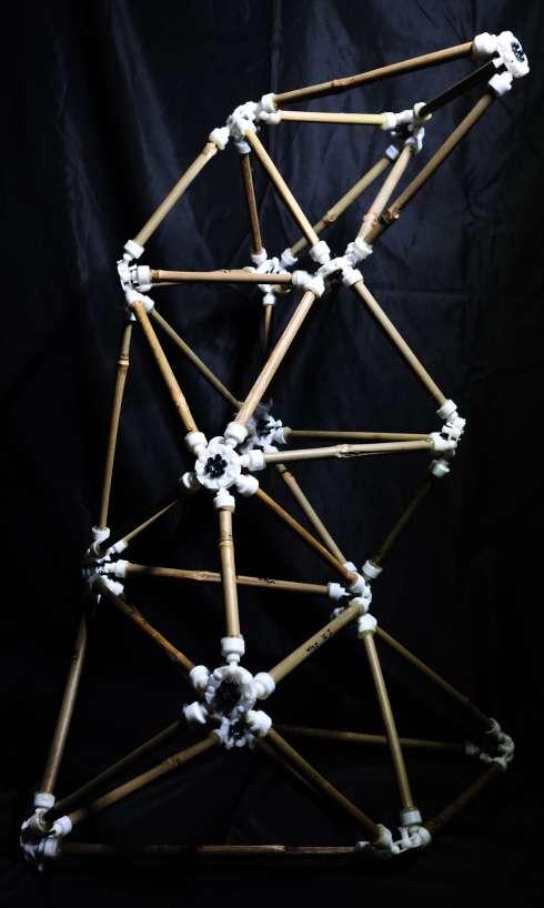
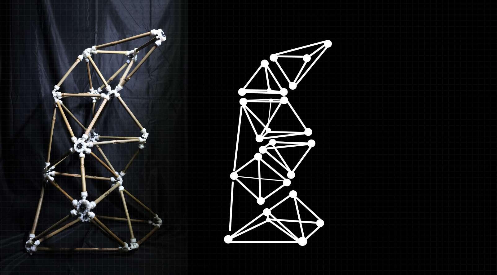
■A section of the full scale theatre was pulled out and simplified to tial with the components potentials in response to the design theory. The scale was then further simplified to create a 1:1 scale model using the developed component. This results in a 1.8 meter high 1:1 scale assembly.

Arch space
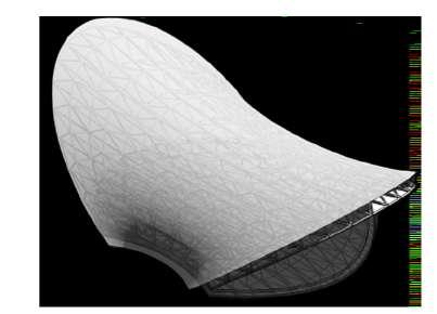
■The chosen design is a large spatial area formed using the space truss code along side the warren truss system.
■This section was randomly chosen to explore its potential for standalone assembly, testing its ability to self-stand and reach capacity.
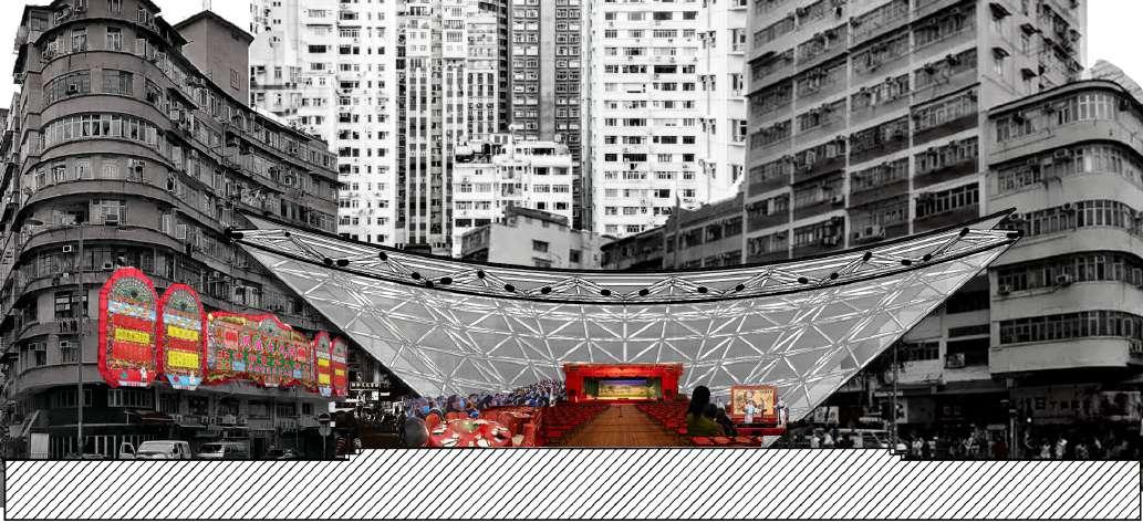

0.50M 4.80M 5.30M 15.50M 9.50M
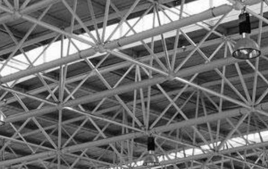
Assembled prototype
Initial prototype
Showing node potential
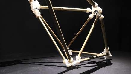
 Testing model
Render of section of full scale model
3
8-Connecting Hub
The triangle prism is then built section by section once the shape is formed the components will lock in place
As the structure gradually builds up, gravity and the weight of the top of structure will begin to apply pressure on the foundation which will then form the structure and stand on its own Step 1
Building the foundation of the model. This
6-Connecting Hub
Step 2 Step
was built
to support the entire structure 8 4 4 4 3 7 7 6 5 6 6 5 5 4 3 7
part
first
●
●
●


1 6 6 7 7 8 8 8 9 9 10 10 11 13 13 14 15 16 16 15 14 Bamboo - Terminal Parts Assembly △WARNING △CAUTION △警告 △注意 50-70外径自适应竹用空间节点 Parts list Feedback form Number. 12345678 Adaptive Bamboo Spcae Hub Adaptive Bamboo Spcae Hub comments or questions TEL: ( )-( ) Date: ( )-( ) -( ) 70mm Outside diameter Bamboo 70mm Diameter Jubilee Clip(additional purchase) Holding Expanding Tel: +86 1234567890 Please contact for order and cooperation Mail: 1030087197@qq.com Address: Queen Elizabeth Olympic Park, 14 E Bay Ln, London E15 2GW Swallowing small parts may cause breathing difficulties, suffocation and other dangers, and children are prohibited from using them. Use age over 16 years old 16岁以上使用 represents the installation steps, the order in which the instructions are instructed. Represents the part number, please pay attention to the distinction, and install it in 小零件吞入会有呼吸困难、 窒息等危险,儿童禁止使用 ●请注意零件的尖锐部分, 以免划伤。 ●请不要切割预制部件,以 免造成无法组装。
sharp parts of
parts to avoid scratches.
Please pay attention to the
the
Please do not cut prefabricated parts to avoid assembly.
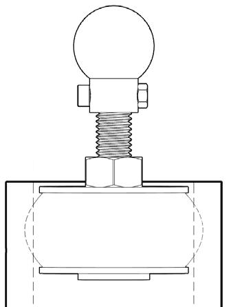
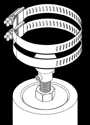
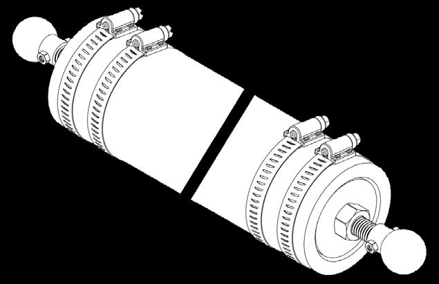
This product is designed for use in mini-compact houses, easy to build, free to choose the site location, and reusable after dismantling. 1 1 2 2 x31 3 3 4 5 3 5 8 8 8 8 8 8 8 4 x7 6 7 5 8 9 10 12 13 11 12 AERO-Hub 50-70 OD bamboo component 竹子-末端零件 组装 1 1 3 2 4 x20 x20 x20 x20 x20 x20 x20 x20 x20 x20 x20 x20 x20
1:1 Model at the bartlett fiftheen show