FUNDAMENTALS Josh Cosford • Contributing Editor
Hydraulic symbology 202 — stacked and piloted industrial valves In Hydraulic Symbology 201, I discussed directional valve symbols from basic construction to valve transitions. For the most part, these symbols pertain to industrial stack valves, although cartridge valve symbology is similar. When the stack valve — aka CETOP, ISO or “D-something” valve — is drawn in a circuit, however, it looks much different. Shown below in Figure 1 is a simple circuit employing two cylinders assisted by various accessory valves. I haven’t covered the design and function of pressure, flow or check valves, so ignore them for now. What’s important to observe is the relatively linear method of drawing each subcircuit, with the pump pushing through all the valves and then eventually onto the cylinder.
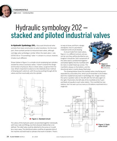
no way to know, and from a design standpoint, how it is plumbed is irrelevant to the circuit drawing. A circuit made from stack valves, Figure 2, is a different animal, and you can be sure they will be plumbed as you imagine it should be. Each component of the valve stack is sandwiched together and bolted tightly into the manifold with Figure 2. tie-rods or socket head cap screws. The Stack valves manifold is always on the bottom, and the | Hengli America directional valve is nearly always fixed atop. The drawing below shows the stacked valves interfacing and separated by a boundary line, which you’ll remember is the brokendash line I explained way back in Symbology 101. Image 3 shows the same 2-position valve on the left with the 4/3 valve again on the right. Fluid enters the left side of the manifold at the P port and feeds oil equally to each valve station. This manifold has two stations, but I’ve seen up to as many as 16 stations machined into a single bar.
Figure 1. Standard circuit
The valves of this hydraulic system are plumbed together individually with hose, tube and fittings, but their physical relationship is not defined. The relief valve could be attached to the pump or it could be a room away. The directional valves could be at opposite ends of the machine and both lead to cylinders that work in tandem. There’s 24
FLUID POWER WORLD
2 • 2020
www.fluidpowerworld.com
Figure 3. Stack valve circuit