






Get the components needed for your material handling system from AutomationDirect, a trusted supplier in the industry for over 30 years. Check out our selection of mechanical and pneumatic components, as well as our wide array of control and automation products.


Industrial vision systems can improve the operation of material handling applications. Sometimes these are used in place of barcode scanners, where the accuracy of reading labels of potentially poor quality is favored over speed. Many times these products are used in quality control applications as well. Like barcode scanners, these systems can range from simple to very complex.

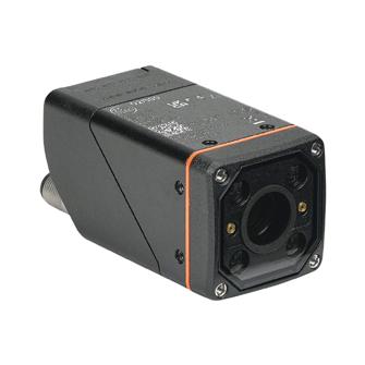


2D Machine Vision Cameras Starting at $995.00 (CS60-BM28-EP15/300)


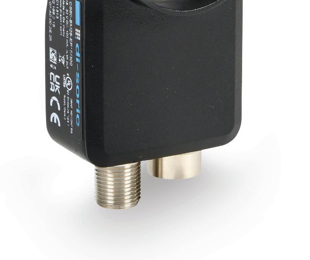


The di-soric CS-60 series 2D cameras have an integrated lighting system and interchangeable S-Mount lenses, which allow for the use of various filters and accessories. In conjunction with the free nVision-i software, these cameras provide an ideal solution for applications that require increased flexibility or handle complex inspection tasks. Common applications include quality inspection of components, vision-assisted robotic grasping, and other related tasks.
di-soric 2D machine vision cameras feature:
• A wide variety of focal lengths through M12 interchangeable lenses
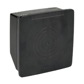
2D machine vision cameras offer precise, high-speed inspection and measurement in manufacturing. Their advanced image processing capabilities ensure accurate defect detection, part positioning, and quality control. Easy integration and user-friendly software reduces setup time and complexity.
• Image correction and calibration
• Reliable and fast, high-performance image processing tools
• Ethernet communications support for TCP/IP, FTP Client, SFTP Client, PROFINET Client, and EtherNet/IP
• 3 inputs and 5 discrete outputs (NPN/PNP)
• Integrated high-power white or red LED illumination
• Onboard logic engine
• Robust, compact housing with IP67 rating





Successful engineering teams know that diverse perspectives lead to better outcomes. The value of diversity was a common theme among this year’s Top Workplaces for Engineers, announced on our sibling publication, Engineering.com.
As we enter a new season, we’re looking for more organizations where engineers love to work and can thrive in career and life. If you believe your company deserves such recognition and meets the criteria, be sure to nominate it at topworkplaces.com/ engineering-com. Our 2026 winners will be announced in the spring.
Additionally, during this month, our publications celebrate diversity in the workplace by sharing stories of successful engineers from various walks of life. Design World’s annual Engineering Diversity + Inclusion special issue highlights some of these stories, and you can find many more timeless tales of engineering successes on engineering.com/category/edi. This year, we feature engineers who remain steadfast in pursuit of their goals and consistently exceed expectations:
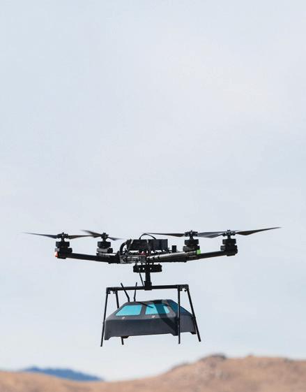
• Harsh Zala designs AI-enabled drones to detect landmines and save countless lives.
• Juniyali Nauriyal built a company focused on sustainability, diversity, and the future of photonics.
• Roy Steinberg inspires engineers with ADHD to excel and leverage their creativity.
• Candis Polite creates enriching, career-launching experiences for engineering interns.
• Ferdando Sarmiento makes aircraft materials and components and encourages engineers to be brave.
• Danna Jensen leads with integrity and designs electrical systems for complex health care projects.
• Maryam Rofugaran designs and manufactures semiconductors for mmWave communications.
• Nikki Maginn is a nuclear engineer who teaches emotional intelligence to engineers so they can soar.
We welcome inspirational stories like these all year round, so if you or someone you know would like to pass wisdom along to aspiring and seasoned engineers alike, email me or any editor on our team.
Thank you to all the remarkable individuals and companies that continue to value diversity, creativity, and excellence in their daily lives. You make the world a better place and elevate us all. DW

Rachael Pasini
rpasini@wtwhmedia.com
linkedin.com/in/rachaelpasini


Rolling bearings’ low-friction characteristics make it possible to reduce bearing friction by half, offering the construction machinery sector the opportunity to achieve significant carbon dioxide savings.
Advances in electronics, battery technologies, and motors themselves have spurred electrification in various industries. Off-highway applications lead.

How maintenance technologies are helping teams identify failure points faster, solve problems more accurately, and implement smarter long-term fixes.
Choosing between grease and oil — it depends on factors such as speed, load, temperature, orientation, and contamination. Here, we explore the advantages and limitations of each lubrication method.
These

EDITORIAL
VP, Editorial Director Paul J. Heney pheney@wtwhmedia.com
Editor-in-Chief Rachael Pasini rpasini@wtwhmedia.com
Managing Editor Mike Santora msantora@wtwhmedia.com
Executive Editor Lisa Eitel leitel@wtwhmedia.com
and
Senior Editor Miles Budimir mbudimir@wtwhmedia.com
Senior Editor Mary Gannon mgannon@wtwhmedia.com
PRINT CREATIVE SERVICES
VP, Creative Director Matthew Claney mclaney@wtwhmedia.com
Art Director Allison Washko awashko@wtwhmedia.com
AUDIENCE DEVELOPMENT
Director, Audience Growth Rick Ellis rellis@wtwhmedia.com
Audience Growth Manager Angel Tanner atanner@wtwhmedia.com

DIGITAL MARKETING
VP, Operations Virginia Goulding vgoulding@wtwhmedia.com
Digital Marketing Manager Taylor Meade tmeade@wtwhmedia.com
PRODUCTION SERVICES
Customer Service Manager Stephanie Hulett shulett@wtwhmedia.com
Customer Service Rep Tracy Powers tpowers@wtwhmedia.com
Customer Service Rep JoAnn Martin jmartin@wtwhmedia.com
Customer Service Rep Renee Massey-Linston renee@wtwhmedia.com
Customer Service Rep Trinidy Longgood tlonggood@wtwhmedia.com
DIGITAL PRODUCTION
Digital Production Manager Reggie Hall rhall@wtwhmedia.com
Digital Production Specialist Nicole Johnson njohnson@wtwhmedia.com
Digital Design Manager Samantha King sking@wtwhmedia.com
Marketing Graphic Designer Hannah Bragg hbragg@wtwhmedia.com
Digital Production Specialist Elise Ondak eondak@wtwhmedia.com
WEB DEVELOPMENT
Web Development Manager B. David Miyares dmiyares@wtwhmedia.com
Front End Developer Melissa Annand mannand@wtwhmedia.com
Software Engineering Manager David Bozentka dbozentka@wtwhmedia.com





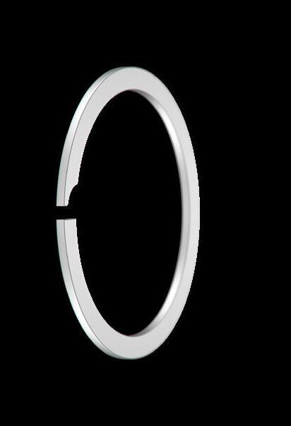
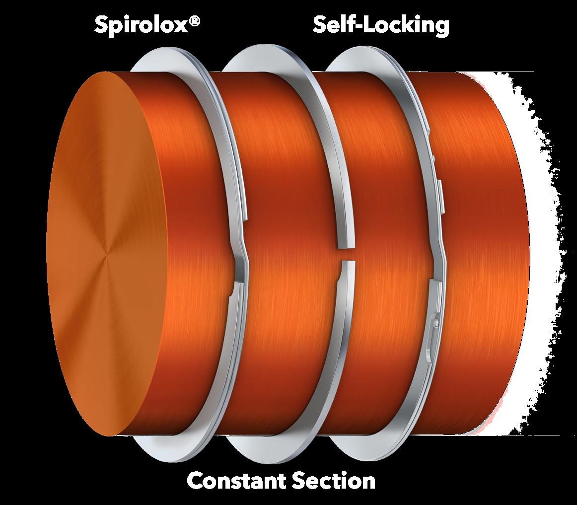
As the inventor of the spiral retaining ring with 100+ years of innovation, here’s why Smalley is The Engineer’s Choice®:
ᘩ 11,000+ standard parts in stock
ᘩ Customizable with No-Tooling-Charges™
ᘩ Trusted performance in 25,000+ applications
ᘩ Award-winning quality backed by leading industry certification
Smalley Retaining Rings
ᘩ No Ears to Interfere®
ᘩ High RPM Capacity
ᘩ Easy install and removal
ᘩ Diameters from .118" to 120" in 40+ materials


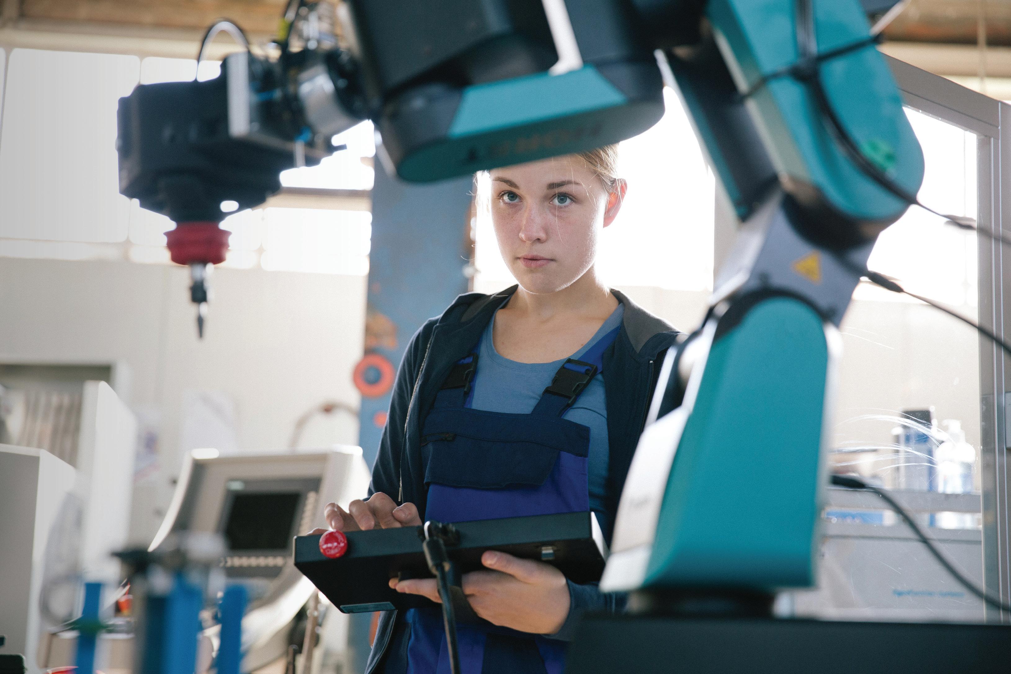
Earlier this year, Festo added new sizes and capabilities to its EHMD line of compact grippers. These grippers are suitable for life science automation applications that require gripping and rotating small objects in confined spaces. An optional module with Z-compensation automatically adjusts to cap thread pitch without moving the Z-axis, eliminating changeover times. EHMD grippers come in 40-mm and now 50-mm sizes.
The EHMD is used in applications such as in vitro diagnostics, cell or genomic research, and quality inspection in the biotech and pharmaceutical industries. This gripper line can also be used in the preparation and analysis of samples; loading centrifuges; gripping, rotating, and placing microwell plates; and opening and closing varioussized vials.
Combined with a 3D gantry and a camera, the EHMD can be integrated into systems that perform quality inspections, read barcodes, and print labels. Outside of lab device applications, EHMD can be used in light assembly and in the electronics industry.
The EHMD comes in a fully electric version or with a pneumatic gripper. When powered by the Festo multi-protocol servo drive CMMT-ST, EHMD grippers can grasp and turn with variable levels of force. DW
Festo • festo.com

WHITTET-HIGGINS manufactures quality oriented, stocks abundantly and delivers quickly the best quality and largest array of adjustable, heavy thrust bearing, and torque load carrying retaining devices for bearing, power transmission and other industrial assemblies; and specialized tools for their careful assembly.
Visit our website–whittet-higgins.com–to peruse the many possibilities to improve your assemblies. Much technical detail delineated as well as 2D and 3D CAD models for engineering assistance. Call your local or a good distributor.
Battery production requires fast, efficient, and repeatable processes. Linear guides play a crucial role here, as they must dynamically move and position different loads with precision. The following tips from Bosch Rexroth show how engineers can optimally meet the industry’s diverse requirements along the value stream.
1. Select resistant materials for dry rooms and electrolyte contact For electrolyte and cell production, the materials used must be suitable for dry rooms and withstand the electrolytes’ corrosive effect. To prevent plastics from becoming porous
and aging prematurely due to the highly dehumidified air, Bosch Rexroth uses materials such as polyacetal (POM) or thermoplastic elastomers (TPE), including suitable adhesives, lubricants, and sealants, for nearly all components. Guideways made with corrosion-resistant materials (NR 2) and hard chromium plating are also part of the portfolio.
2. Use high-performance components for higher productivity
Linear guides must perform extremely well, for example, in the precise guidance of distance control in roll-
to-roll processes such as calendering (rolling) or slitting (cutting). The highperformance ball rail systems BSHP from Bosch Rexroth carry out such tasks with exact rail surfaces and vibration-optimized runner blocks. For short cycle times, belt-driven Rexroth ball rail systems achieve acceleration values of up to 50 m/sec² and speeds of up to 5 m/sec. Versions with cam rollers and high-speed runner blocks achieve 10 m/sec.
When laser cutting electrode foils for any type of battery cell, the IMS position measuring system integrated into the linear guide, combined with linear motors, helps ensure maximum

efficiency with minimum tolerances. The non-contact and wear-free measuring principle with decoder integrated into the runner block is insensitive to contamination and achieves comparable repeatability to glass scales of up to ±0.25 µm. The shock and dynamic characteristics correspond to the respective underlying linear guide.
3. Cover a wide range of requirements with a single source
Bosch Rexroth has a finely graduated portfolio of linear axes with ball screw assemblies or toothed belt drives, various types of seals, and accessories. Laser welding or contacting machines, for example, can be realized compactly and economically with the complementary linear motor modules.
4. Go for flexibility in usage and integration
Module and pack assembly benefits from highperformance linear guides, which can be combined to form ready-to-use linear axes and Cartesian robots. Compared to industrial robots, linear robots often boast higher precision, dynamics, and compactness due to their mechanical properties. Their range of applications covers handling, screwing, and dosing processes as well as camera transport in end-of-line testing.
Engineers can use Bosch Rexroth’s e-tools to select, size, and configure components. With the Smart Function Kits, pre-installed user software can reduce commissioning and program time. The company also creates customer-specific solutions, such as gantry robots for loading, filling, sealing or gluing, screwing or welding.
5. Find sustainable solutions
Linear components and solutions for battery production must also offer a high degree of reliability and sustainability. Look for long-life linear guides that implement the required movements with minimal energy loss and lubricant consumption. Maintenancefree applications, flexible interchangeability, and the exact calculation of relubrication intervals up to the total service life contribute to lower resource consumption.

Solid or hollow shaft, high performance, housed and frameless, brushless motors and matching drives for demanding applications.
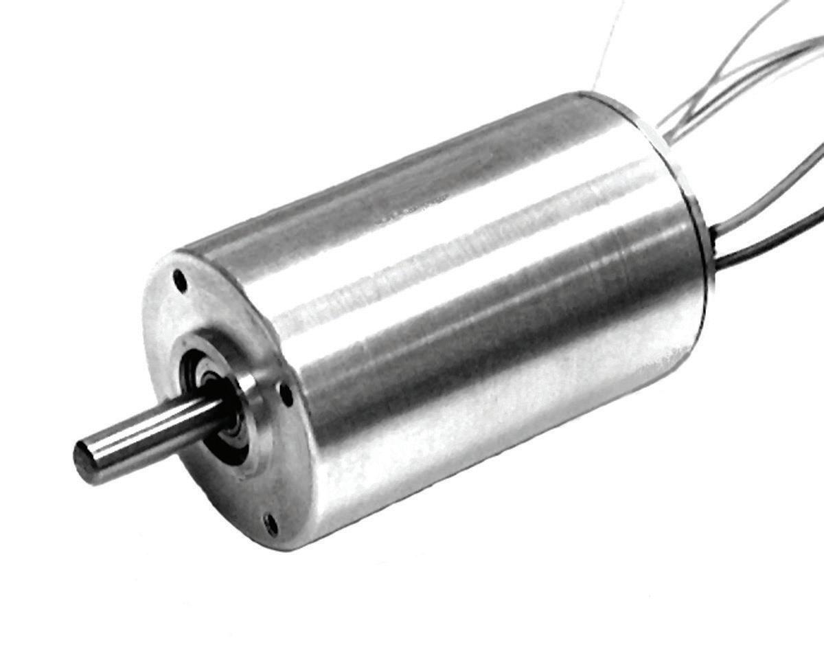
Hall or sensorless motors and drives for surgical tools, aerospace, military, and scientific instrument applications. Custom drive programing and designs available.
Motors up to 95% efficient, power up to 1,500 watts.
Highest power density in the industry.
Operating temperatures from -73C to 150C
Slotless and slotted designs. Available with encoders and gearheads and separate or integral electronics.
Quantities 1 to 5,000.

www.koford.com
Contact us at mail@koford.com
Bosch Rexroth • boschrexroth.com



Radial shaft seals are a wellestablished machine component that is used millions of times across various industries. They ensure dynamic and static sealing on the shaft and help distribute lubricant effectively. However, even with all the routine, many aspects of what exactly happens in the contact between the seal and the shaft have been unclear because it is impossible to observe the relevant areas in practice.
A recent advance comes from Freudenberg Sealing Technologies and Freudenberg Technology Innovation, which jointly developed the Freudenberg Integrated Radial Shaft Seal Simulation Tool (FIRS³T). FIRS³T offers a new level of insight through simulation by delivering precise,
traceable predictions of sealing performance under varying loads and conditions, which enables the development of an optimum design and functionality.
To this end, FIRS³T contains considerable and complex knowledge. Numerical descriptions include realistic surfaces in contact between the sealing ring and shaft, macroscopic aspects (such as contact pressure distribution), the distortion of the seal during dynamic operation, and lubricant simulation with viscosity and flow factors on the surfaces. All influencing variables can be adjusted flexibly in the calculation model, offering a simulated view into the system.
The process also accelerates development and eliminates the time-consuming, labor-intensive, and therefore costly steps of multiple prototype iterations with the associated tooling and physical validation, which can take months for complex seals when using conventional methods.
In addition to performance gains, simulation reduces development timelines from months to days, with only one physical prototype typically needed for validation. This efficiency is particularly valuable for large-scale applications such as wind turbine seals, where testing is costly. Such seals have a diameter of around two meters, which means high prototype and testing costs. FIRS³T can reduce these factors, but
above all, it can offer seal designs with superior performance in this case as well.
Using its FIRS³T solution, Freudenberg’s new radial shaft seal is now a reality. It is designed for a wide range of hydraulic pump and motor applications operating at varying pressure levels. It has a redesigned sealing lip with an optimal contact width under all pressure conditions, ensuring excellent wear behavior at pressures of up to 5 bar while also providing robust sealing at lower pressures. The seal offers a longer service life and even greater reliability, which translates into lower maintenance costs and longer intervals between servicing. For hydraulic systems, the result is a seal designed to meet demanding operating requirements more effectively and more quickly than before.
FIRS³T is set to be a standard tool at Freudenberg Sealing Technologies in the future. The company is continuously refining the simulation model as their practical experience accumulates, so they can obtain increasingly precise information about the sealing performance and properties. DW
Freudenberg Sealing Technologies fst.com

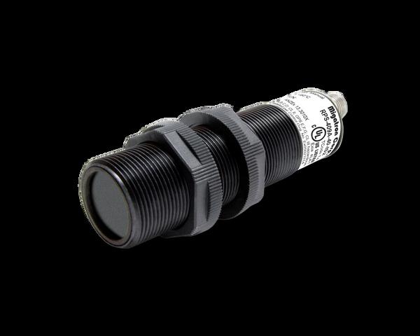
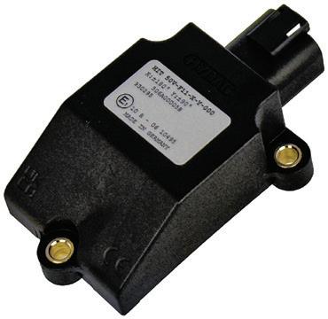
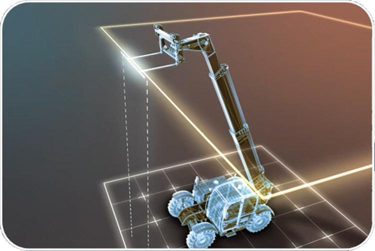
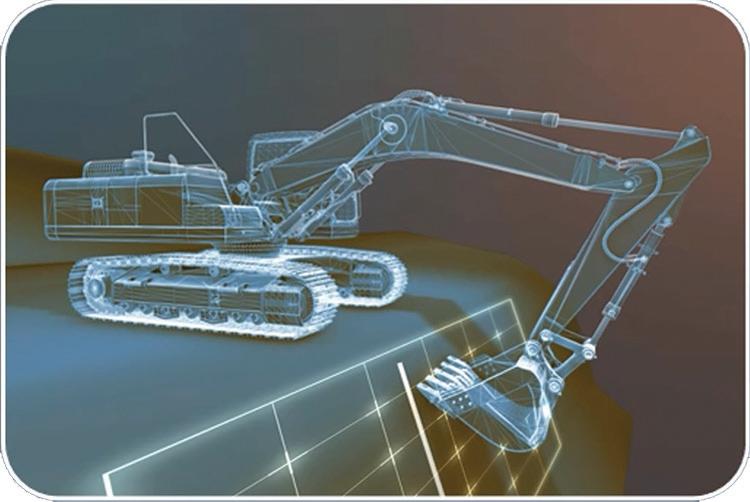
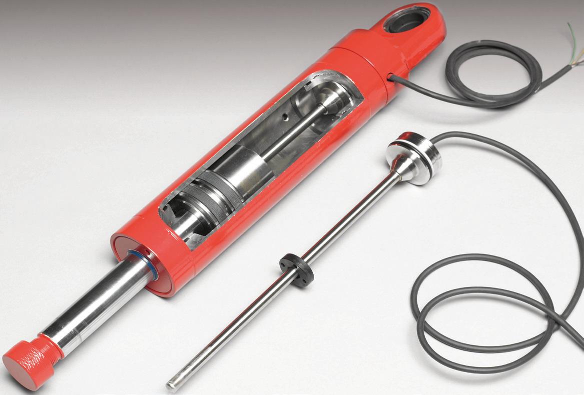
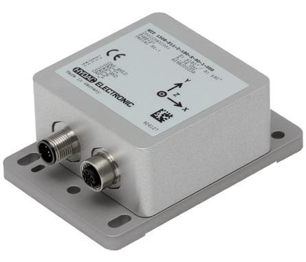
Are you looking for sensors that are easy to integrate, safe and, above all, precise?
The optimum combination of position sensors depends on a wide range of factors, including mechanical integration, the available installation space, the performance dynamics and the respective costs.
HYDAC’s comprehensive approach involves developing the right sensors and the optimum solution for your machine type.


Environmental testing is crucial for packaging design as packaging must protect products from extremes of temperature, humidity, and physical impacts during transportation and storage. Testing can help in selecting materials that are not only effective but also reduce the environmental impact of packaging.
Renishaw recently made a multimillion-dollar investment in a new dedicated facility to test its products under the environmental and electrical conditions encountered during transportation. The new testing facility includes a variety of equipment, including a large electromagnetic compatibility (EMC) chamber, devices
for testing electrical safety, and environmental simulation systems, such as accelerated life testing. The latter includes electrodynamic shakers that identify the resonant frequency of Renishaw products and then subject them to many years of use in just a few hours.
The new testing facility also houses equipment designed to simulate a wide range of conditions faced during transportation. This includes temperature ovens, climatic chambers, a negative-pressure vessel, and a positive-pressure vessel.
Transport temperature testing is designed to replicate the extreme temperature cycles, from -25 to
70° C, with each temperature maintained for 16 hours. This test cycle is repeated to give a combined 32 hours at each temperature extreme. Temperature ovens simulate the harshest environments, such as an unpressurized hold on an air freight journey. If a plane ascends to a high altitude, the air temperature can drop significantly, whereas upon landing in a warm country, the package might experience much higher temperatures.
Renishaw also conducts humidity testing using climatic chambers, which maintain a constant temperature of 42° C and a relative humidity of 93%. Humidity testing is crucial for checking the integrity of vacuum-sealed
products and ensuring that moisture does not penetrate the packaging. This is particularly important for products that might be exposed to varying humidity levels during transit through different countries.
The company also tests products for their ability to withstand negative and positive pressure environments. Negative pressure testing is conducted in a vacuum chamber to simulate highaltitude, non-pressurised conditions equivalent to 55 kPa (550 mbar) for 16 hours. This is particularly important for sealed product packaging that might be transported inside aircraft cargo holds with large pressure differentials at high altitude. Positive pressure testing is also performed on products that require IPX8 certification using a pressure vessel that simulates immersion in water at an equivalent depth of 10 m (an absolute pressure of 2 bar) for a period of 24 hours.
Another critical aspect of environmental testing is vibration testing, which simulates the g-forces that a package might experience during transit, whether by road, sea, or air. The lab is equipped with three electrodynamic shakers that can apply various vibration profiles to the product packaging. The tests are conducted over three axes to replicate the worst-case scenarios. The vibration profiles include sinusoidal, random, and pulse shock tests, each designed to simulate different types of vibration and impact.
All the package tests include packaging with a product inside, and the sign-off criteria for a successful test is the powering up of this product without any observed degradation in performance. DW


• EDITED BY MIKE SANTORA
3D Systems recently announced that the Company is collaborating with researchers from Penn State University and Arizona State University on two projects sponsored by NASA. The projects are intended to enable alternatives to current thermal management solutions. Severe temperature fluctuations in space can damage sensitive spacecraft components, resulting in mission failure. By combining applications expertise with 3D Systems’ additive manufacturing solutions comprising Direct Metal Printing (DMP) technology, tailored materials, and Oqton’s 3DXpert software, the teams are engineering sophisticated thermal management solutions for the demands of next-generation satellites and space exploration.
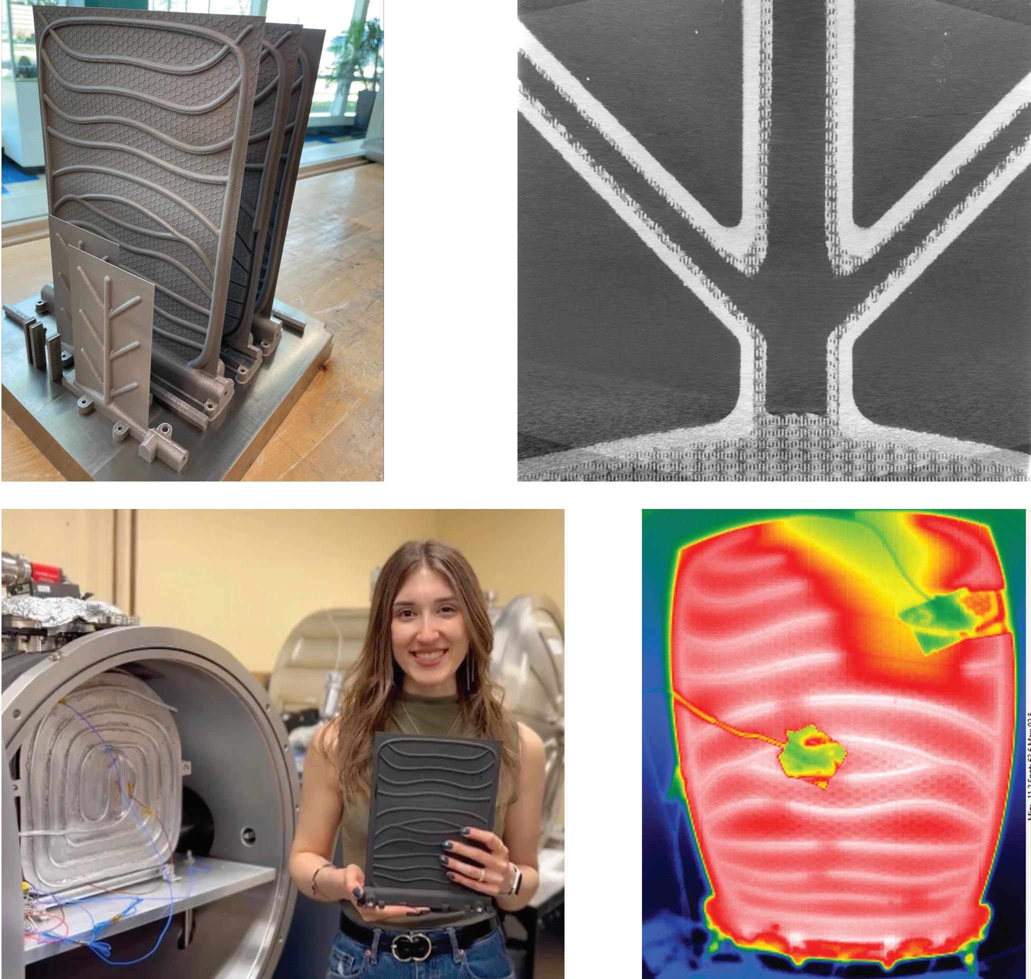
The project, led by researchers with Penn State University, Arizona State University, and the NASA Glenn Research Center in collaboration with 3D Systems’ Application Innovation Group (AIG) has resulted in processes to build embedded high-temperature passive heat pipes in heat rejection radiators that are additively manufactured in titanium. These heat pipe radiators are 50% lighter per area with increased operating temperatures compared with current state-of-theart radiators, allowing them to radiate heat more efficiently for high power systems. Additionally, a project led by researchers at Penn State University and NASA Glenn Research Center with 3D Systems’ AIG yielded a process to additively manufacture one of the first functional parts using nickel titanium (nitinol) shape memory alloys that can be passively actuated and deployed when heated. This passive shape memory alloy (SMA) radiator is projected to yield a deployed-to-stowed area ratio that is 6× larger than currently available solutions, enabling future high-power
communications and science missions in restricted CubeSat volume. When deployed on spacecraft, such as satellites, these radiators can raise operating power levels and reduce thermal stress on sensitive components, preventing failures and prolonging satellite lifespan.
Traditionally, heat pipes have been manufactured with complex processes to form porous internal wick structures that passively circulate
AC
B
fluid for efficient heat transfer. Using Oqton’s 3DXpert software, the Penn State/Arizona State/NASA Glenn/3D Systems project team embedded an integral porous network within the walls of the heat pipes, avoiding subsequent manufacturing steps and resulting variability. Monolithic heat pipe radiators were manufactured in titanium and nitinol on 3D Systems’ DMP technology. The titaniumwater heat pipe radiator prototypes
D

A. Concept for additively manufactured shape-memory-alloy (SMA) radiator with radial heat pipe branches deploying from compact stowed form.; B. Prototype SMA demonstrator with highly compliant bellows heat pipe arms.; C. Thermal image of SMA branching bellows heat pipe, showing nearly isothermal operation. Penn State University
were successfully operated at temperatures of 230°C and weigh 50% less (3 kg/m2 versus over 6 kg/m2), meeting NASA goals for heat transfer efficiency and reduced cost to launch for space-based applications.
The Penn State/NASA Glenn/3D Systems team is also pushing the boundaries of what is possible with metal AM by developing a process to 3D print passively deployed radiators with shape memory alloys. The chemistry of these materials can be tuned to change shape with application of heat. SMAs can withstand repeated deformation cycles without fatigue and exhibit excellent stress recovery. The team again used 3DXpert to design the deployable spoke structure of the radiator. This was then 3D printed in nitinol (NiTi), a nickel-titanium shape memory alloy, using 3D Systems’ DMP technology. When affixed to a spacecraft such as a satellite, this device can be passively actuated and deployed when heated by fluid inside, thus removing the need for motors or other conventional actuation in space. The passive shape memory alloy radiator developed by the team offers transformative advances with projected deployed-to-stowed area ratio that is 6× larger than what is currently considered stateof-the-art (12× versus 2×) and 70% lighter (<6 kg/m2 versus 19 kg/m2).
“Our long-standing R&D partnership with 3D Systems has
enabled pioneering research for the use of 3D printing for aerospace applications,” said Alex Rattner, associate professor, The Pennsylvania State University.
“The collective expertise in both aerospace engineering and additive manufacturing is allowing us to explore advanced design strategies that are pushing the boundaries of what is considered state-of-theart. When we complement this with the software capabilities of 3DXpert as well as the low oxygen environment in 3D Systems’ DMP platform, we can produce novel parts in exotic materials that enable dramatically improved performance.”
According to Research and Markets, the global market for additive manufacturing in the aerospace industry was estimated at $1.2 billion in 2023 and is projected to reach $3.8 billion by 2030. Additive manufacturing is making a significant impact by enabling the production of airworthy parts with reduced weight and improved performance. In the last decade alone, 3D Systems has worked alongside aerospace industry leaders to produce more than 2,000 structural titanium or aluminum alloy components for space flight, and over 200 critical passive RF flight parts. There are currently more than 15 satellites in orbit with 3D Systems-produced flight hardware on board. DW
3D Systems • 3dsystems.com

® ® Interpower® manufactures North American and international cords, cord sets, and IEC 60320 components with over 2 million products in stock. Need cord clips molded onto your cords to prevent tripping? Need your cords hanked, coiled or tied? Bagged and boxed? Want barcodes to place your cords in the exact aisle and bin for storage? Need filters, ferrites or ferrules? Ring or spade terminals? Heat-shrink tubing? NO minimum order requirements? Try Blanket or Scheduled orders for one calendar year—Blanket ordering: lock in your price, and order cords throughout the year when you need them. Scheduled orders: set predetermined dates year-round to receive your cords.
Toll-Free Phone: (800) 662-2290
E-mail: info@interpower.com
Business Hours: 7 a.m.–5 p.m. CST Order Online! www.interpower.com
Volkswagen’s digital trajectory reveals both the promise of technology adoption and the hurdles of industrial-scale implementation.
the line
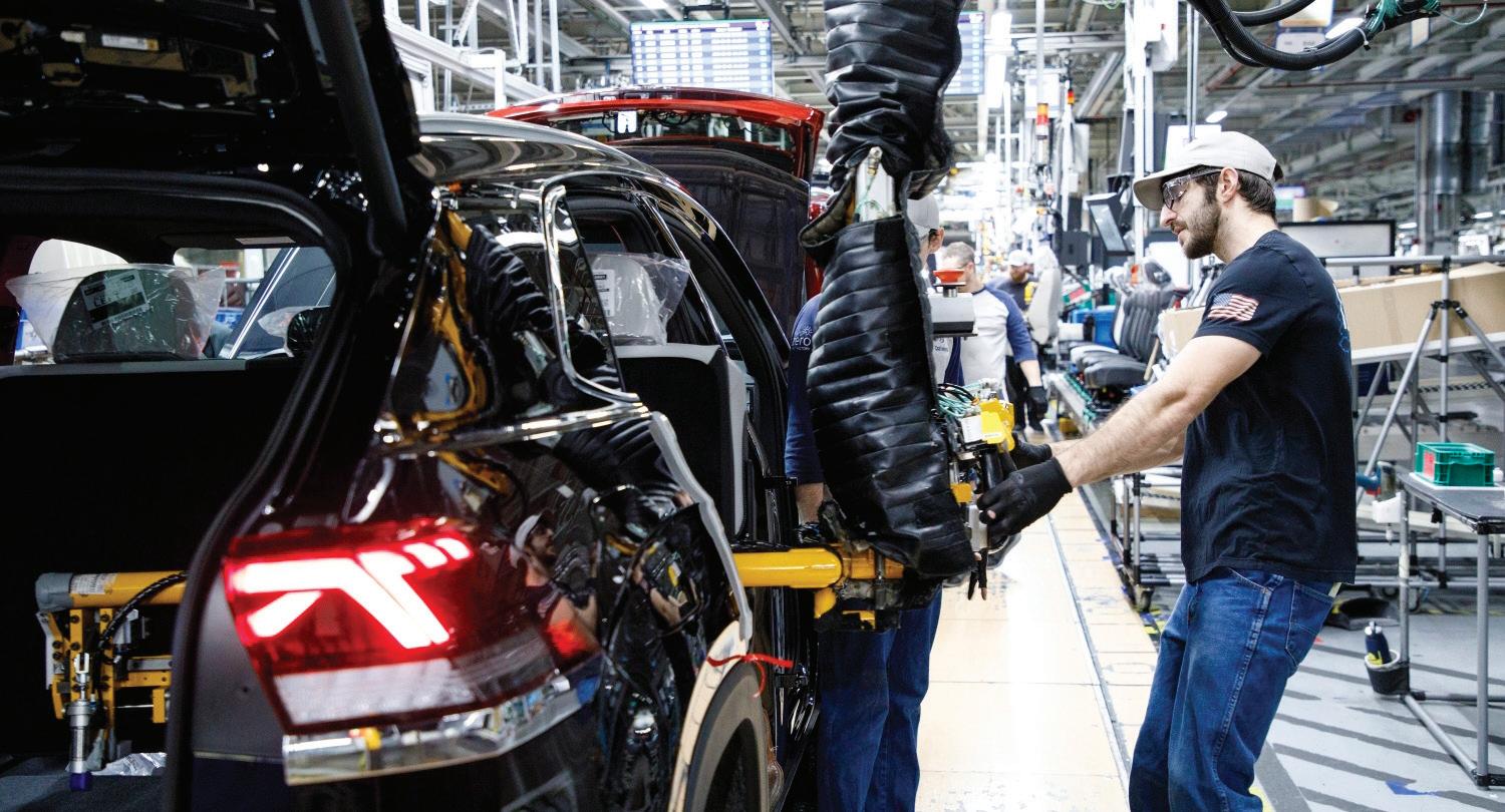
Volkswagen’s recent strategic moves highlight a company at the crossroads of transformation. On one hand, VW is making bold investments in AI-driven engineering and forging strategic alliances to position itself as a leader in next-generation automotive innovation. On the other, it faces the stark realities of largescale execution—rising manufacturing costs, operational challenges, new electric vehicle (EV) entrant competition, and financial pressures.
To stay competitive, VW has embraced generative AI, digital twins, and software-defined vehicles. Announced in December 2024, its partnerships with PTC and Microsoft to develop Codebeamer Copilot aims
to revolutionize Application Lifecycle Management (ALM) with AI automation. Meanwhile, the adoption of Dassault Systèmes’ 3DEXPERIENCE platform signals a commitment to integrating model-based engineering (MBE) for optimized vehicle development.
At the same time, Volkswagen’s $5.8 billion investment in an alliance with Rivian showcases a strategic bet on the future of electric mobility. However, alongside these forwardlooking investments, Volkswagen must grapple with fundamental execution challenges—managing rising production costs, navigating supply chain disruptions, and ensuring that its transformation efforts deliver tangible business outcomes.
Volkswagen’s collaboration with PTC and Microsoft to develop Codebeamer Copilot signals a strong commitment to leveraging generative AI in Application Lifecycle Management (ALM). Codebeamer is being augmented with AI-driven automation to enhance software development efficiency, a critical step as automotive manufacturers increasingly shift towards software-defined vehicles. Software is no longer just an enabler; it is now at the heart of automotive product differentiation. For Volkswagen, a legacy automaker, competing with software-native disruptors requires a
fundamental shift in how vehicle development is structured.
Codebeamer Copilot represents more than an AI-enhanced ALM tool—it is part of a broader shift toward agile, continuous software deployment, ensuring that VW’s vehicles remain at the forefront of digital innovation.
Simultaneously, VW’s adoption of Dassault Systèmes’ 3DEXPERIENCE platform aims to optimize vehicle development processes. This move reinforces the industry’s pivot towards integrated digital twins, where real-time collaboration and modelbased engineering (MBE) accelerate product lifecycle governance. The 3DEXPERIENCE platform aligns with the growing need for crossfunctional collaboration between mechanical, electrical, and software engineering teams, bridging gaps that have historically slowed down the development process. While these investments showcase Volkswagen’s intent to streamline development, execution remains key—successful deployment will hinge on cultural adoption and seamless integration with legacy systems.
Volkswagen’s $5.8 billion partnership with Rivian announced in November 2024 signals a strategic hedge against legacy constraints.
The alliance provides VW with access to Rivian’s advanced EV architecture, allowing the German automaker to accelerate its EV portfolio without reinventing the wheel. In return, Rivian gains the financial backing and industrial scale necessary to compete in an increasingly saturated EV market.
This collaboration is emblematic of a broader trend in the automotive industry: the shift from closed innovation models to open collaboration. OEMs are recognizing that building everything in-house is neither cost-effective nor agile enough for the rapid technological shifts defining the industry. By working with Rivian, VW positions itself to benefit from the startup’s agility while bringing its own massproduction expertise to the table. However, alliances alone are not enough. To realize the full potential of this partnership, VW must overcome

Codebeamer is an ALM platform for advanced product and software development. PTC

® Get the exact cord set you need with Interpower North American and international cord set customizations. From country-specific wall plugs to IEC 60320 connectors, plug connectors, inlets and outlets, to cord lengths, packaging, labeling and barcoding, and cord clips for safety, Interpower has the customization options you need while still maintaining their 1-week U.S. lead times. And, if what you need is in stock, those stocked items ship the same day as ordered. Currently Interpower has nearly 2 million cords and components in stock. Interpower—cords made your way.
Toll-Free Phone: (800) 662-2290
E-mail: info@interpower.com
Business Hours: 7 a.m.–5 p.m. CST Order Online! www.interpower.com
internal friction—balancing traditional automotive development processes with the more iterative, software-driven approach championed by Rivian. Success will depend on VW’s ability to integrate new ways of working without disrupting existing operations.
While Volkswagen continues to push forward with its digital and electrification strategies, operational challenges remain a persistent theme. Rising material costs, supply chain bottlenecks, and production inefficiencies have placed significant financial pressure on the company. In 2024, VW reported 4.8 million vehicle deliveries—an impressive figure, but one that comes against the backdrop of increasing competition from Tesla, Chinese
automakers such as local market leader BYD, and emerging EV startups.
Manufacturing complexity is another hurdle. Unlike Tesla, which designs its vehicles with highly streamlined production methods, VW is contending with legacy platforms that require significant re-engineering to accommodate next-generation propulsion systems and digital architectures. This tension between past and future is not unique to VW but serves as a reminder that digital transformation is as much about unlearning as it is about innovation.
To bridge this gap, Volkswagen must double down on operational efficiency while ensuring that its transformation investments deliver clear, measurable returns. This means refining its global production footprint, streamlining supplier relationships,
Longer lasting Belts, HEHT Split Spools -- no regrind wide_Layout 1 8/22/2023 6:05 PM
Round, Flat, Vee and Poly-V belts and pulleys

We use 100% virgin urethane (no regrind waste). Makes stronger, longer lasting belts.
« Abuse Resistant Belts work where others fail.
« Super Strong Joints are virtually unbreakable.
« High Tension Belts move heavier loads.
« HEHT black belts double capacity.
Split Line-shaft Spools
« Low cost, highly efficient, elastic flat belts. Dura-Belt
l High precision. Reasonable price. l Easy to install. Zero downtime.
Round, Flat, Vee and Poly-V Belts and Pulleys
800-770-2358 614-777-0295 Fax: 614-777-9448 www.durabelt.com
and investing in workforce upskilling to ensure that its employees are equipped for the future of mobility.
Volkswagen’s trajectory exemplifies the duality of digital transformation: bold investments in AI-driven engineering and strategic alliances, juxtaposed with the realities of industrial-scale execution. The success of these initiatives will depend on VW’s ability to navigate integration complexities, mitigate disruption risks, and sustain operational resilience.
For manufacturing engineering leaders, the key takeaway is clear: transformation is not just about adopting new technologies but ensuring their successful convergence with business imperatives. It requires a relentless focus on execution—aligning investments in AI, ALM, PLM, and EV strategy with pragmatic, scalable implementation roadmaps. The future of Volkswagen, and indeed the broader automotive industry, will be defined by those who can master this balancing act.
As digital and physical converge faster than ever, Volkswagen’s journey serves as a crucial case study that highlights both the promise and pitfalls of large-scale digital reinvention. The automaker’s success will hinge on its ability to harmonize technology adoption with industrial pragmatism, ensuring that innovation is not just pursued but effectively realized at scale. DW
• EDITED BY MIKE SANTORA
At EMO 2025 last month, Siemens introduced its Optimize MyProgramming /3D Scanner, a new software solution that the company expects to fundamentally transform shop floororiented CNC programming. This software combines new 3D analysis technologies with programming right on the CNC control, maximizing efficiency, precision, and quality in production. Optimize MyProgramming /3D Scanner is part of the Siemens Xcelerator portfolio and enhances it with advanced technologies for process optimization in manufacturing.
Programming right on the control
The solution is distinguished by its direct integration into Sinumerik Operate, which allows users to create and optimize programs on the control. Seamlessly transferring geometric information from 3D CAD models into programs eliminates the need for cumbersome and errorprone manual input. This function saves significant time and costs while minimizing sources of error.
Efficiency and quality thanks to automatic data transfer
The 3D Scanner offers customized suggestions for manufacturing strategies based on geometric features. This function not only leads to time and cost savings, but it also allows better parameterization of machining cycles. This prevents programming errors, which means a consistently high quality in production. By integrating Optimize MyProgramming /3D Scanner, machine manufacturers can increase the attractiveness of their products in a competitive market and convince customers through measurable efficiency and quality advantages in production.
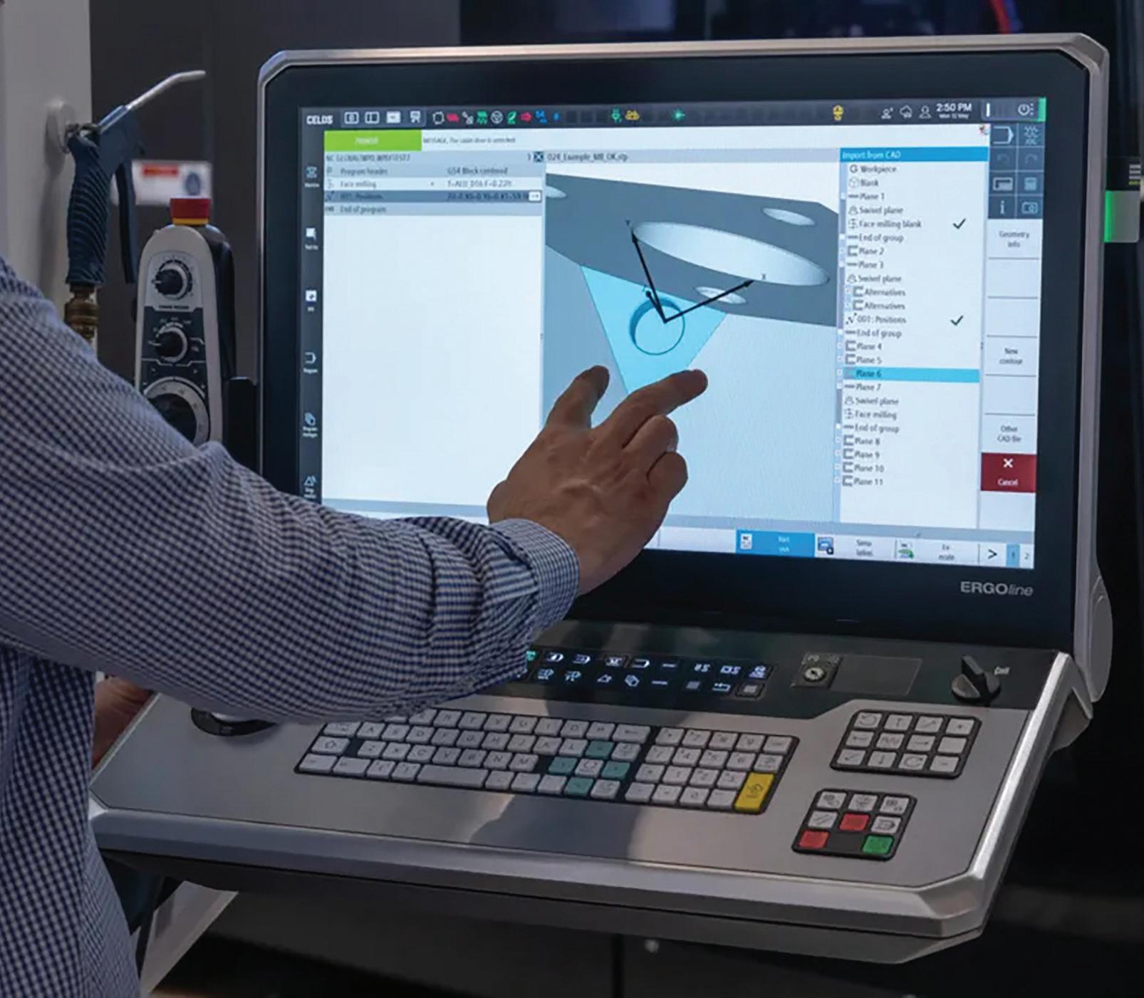
With Optimize MyProgramming /3D-Scanner, users can create and optimize programs right on the controller.
The software’s successful pilot with machine manufacturer DMG MORI demonstrated that the 3D Scanner is a powerful complement for optimizing manufacturing processes and can be seamlessly integrated into existing systems. Optimize MyProgramming /3D Scanner is integrated as a standard option in all DMG MORI machines equipped with Sinumerik One. The software will be available for purchase starting in autumn.
Optimize MyProgramming /3D Scanner is offered as a perpetual license for real machine tools and as an option for their digital twin based on Run
MyVirtual Machine. Experienced service providers offer support with comprehensive consulting and implementation. This ensures seamless integration of the software into modern production environments.
With Optimize MyProgramming /3D Scanner, Siemens reinforces its commitment to shaping the future of the manufacturing industry with advanced technologies and efficient solutions. The software enables manufacturing companies to make higher-quality products with more efficient production processes. DW
Siemens • siemens.com
• EDITED BY MIKE SANTORA
A growing population means an increase in energy consumption. However, refineries often need to operate from their existing footprint. Because of this, sites can become congested as existing space is allocated for new process equipment.
Over time, this makes maintenance more complex. With a facility full of live and tightly packed critical equipment, safety becomes the key priority; closely followed by efficiency.
When a refinery undergoes maintenance activity, some operations at the site must halt while essential work is carried out. Therefore, any unnecessary downtime can add significant cost to a project.
As part of maintenance activity at ExxonMobil’s Fawley Refinery in the
As part of maintenance activity at ExxonMobil’s Fawley Refinery in the UK, Mammoet recently supported with the exchange of a reactor head in the FCC (Fluid Catalytic Cracker) unit.
UK, Mammoet recently supported with the exchange of a reactor head in the FCC (Fluid Catalytic Cracker) unit.
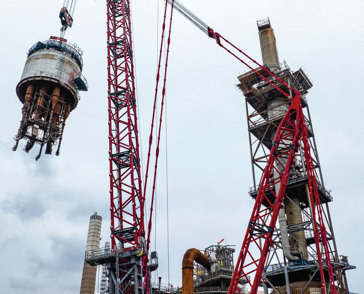
Mammoet used its self-erecting FOCUS30 pedestal crane, replacing the old 356t reactor head in less time than other cranes while taking up a footprint slightly larger than a five-a-side football pitch.
In 2006, Mammoet supported the exchange of a regenerator at the same site. The PT50 ring crane was used, which had a significantly higher load moment and smaller footprint than commercially available crawler cranes at the time.
Despite this, its boom had to be carefully assembled over live pipework as there wasn’t enough free space to construct it at ground level.
Eighteen years on, with even less site space to carry out this project, Mammoet’s engineers suggested using the FOCUS30. Dubbed ‘the crane that builds itself’, it has been specifically designed to perform heavy lifting in facilities with complex infrastructure and limited space.
This high-capacity pedestal crane has a boom that is erected vertically in sections, instead of horizontally. Each boom section is inserted like a jacking cartridge before being lifted to make room for the next underneath.
This not only allows for faster assembly, but for the crane to be
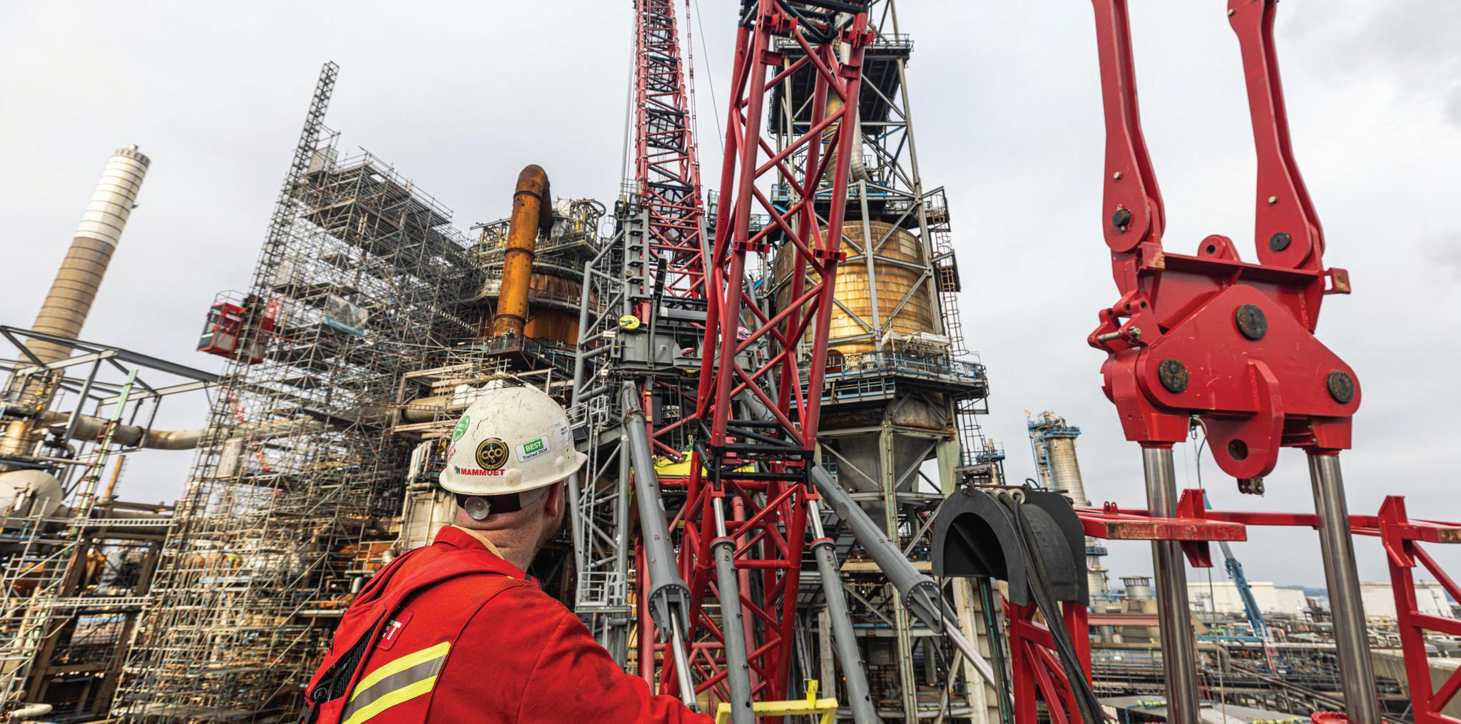
The FOCUS30 is also much less susceptible to high winds than alternative crawler cranes, which would typically have to boom down at around 16 m/s wind speeds, causing significant disruption on site.
built in a footprint measuring just 34 by 42 meters. It also means that the crane’s boom does not need to be laid flat before erection, potentially blocking access roads on site.
At the planning stage, Mammoet’s engineers conducted a full 3D scan of the refinery’s reactor and, using in-house planning software Move3D, created a visualization of the project to show how the pedestal crane would be positioned on site.
By using this software in combination with 3D scan data, it was possible to identify any clashes in the highly congested site. The lift’s proximity to an absorption column demanded a level of scrutiny and accuracy that couldn’t be provided by a traditional 2D approach.
By carefully positioning the FOCUS30 crane around existing infrastructure, hardly any alterations were needed in the field. Only one large pipe was identified early in the engineering process, and this was able to be removed without delay.
Mammoet designed a specialist lifting beam that could be inserted through the top nozzle of the reactor head and
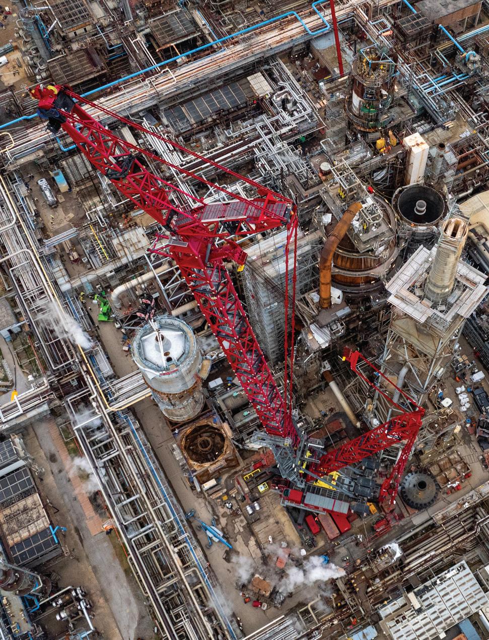
This pedestal crane’s boom is erected vertically in sections, instead of horizontally.
This not only allows for faster assembly, but for the crane to be built in a footprint measuring just 34 by 42 meters. Additionally, the crane’s boom does not need to be laid flat before erection, potentially blocking access roads on site.
clamped to its interior. The lifting beam had two large lifting pads that carried the reactor top from the inside of its plenum. This methodology provided a sure grip of the reactor head as it was lifted.
The FOCUS30 was configured with a divisible superlift tray of 900t and 400t sections, which made movement of the ballast fast and simple, while making sure that the crane did not need to slew over live pipe racks with the load.
The FOCUS30 is also much less susceptible to high winds than alternative crawler cranes, which would typically have to boom down at around 16 m/s wind speeds, causing significant disruption on site. By storm anchoring itself to its own outriggers, the FOCUS30 can withstand conditions more than twice as harsh, giving owners peace of mind projects will not suffer significant wind delays.
The FOCUS30 demonstrates Mammoet’s commitment to supporting its clients in overcoming heavy-lift challenges through innovation and
considered design. It is helping to make refinery maintenance significantly easier, faster, and safer — even as sites grow more complex.
Its use alongside Move3D allows maintenance projects at sites that have existed for many decades, changing year-by-year, to proceed with confidence that every millimeter has been accounted for.
The FOCUS30 has 30,000 tonnemeters of load moment, yet has only one-sixth of the footprint, compared to currently commercially available crawler cranes with comparable strength.
It solves three of the biggest challenges that plant owners face: lifting capacity, space, and time — as Koen Totté, Sales Manager at Mammoet, explained:
“It takes around three to four weeks to assemble the FOCUS30. By comparison, a heavy lift crawler crane would have taken around five weeks.” DW
Mammoet • mammoet.com
• JOSH COSFORD • CONTRIBUTING EDITOR
Preventing hydraulic motor failure involves a combination of proper design, maintenance, and operation practices. Despite resembling hydraulic pumps, motors are unique in that they convert hydraulic energy (in the form of pressure and flow) into rotational energy (in the form of running torque). Hydraulic motors drive winches, wheels and pulleys, to name a few, making them a versatile actuator like none other.
However, when hydraulic motors’ needs are not met, failure is all but guaranteed. Compared to many
other components, hydraulic motors face the most drastic conditions, harsh operating environments and most extreme pressures. To prevent hydraulic motor failures, I’ve compiled a list of 7 steps to help you keep you and your machine happy.
1. Ensure your hydraulic oil is clean, dry and properly viscous. Just as with other hydraulics, contamination is still the number one cause of hydraulic motor failure. Monitor the filter condition by observing its bypass
indicator or changing the element at regular intervals if one is not present.
Motors are the most likely hydraulic component to be entirely submerged in water, such as those used in drive wheels for various mobile machines. Send oil samples regularly to analysis labs to check for water contamination, and use desiccant breathers to prevent excessive moisture.
Finally, employ tactics to maintain the oil within the ideal viscosity range, which requires cooling in warm climates and heating in cold climates. The extremes

of temperature allow for metal-on-metal wear in the heat or possible cavitation and loss of lubrication in the cold.
2. Do not overload your hydraulic motor. Avoid exceeding the torque and speed rating of the motor, which can lead to excessive heat, cavitation due to flow demand when over center, and physical breakage when torque overloads the mechanical and physical capacity of the motor. Side loading should also be monitored since damage to bearings,

seals, and the shaft itself could result in catastrophic failure.
3. Properly install and align your hydraulic motor. Motors use shafts and usually turn other shafts, but they could also insert into gearboxes or other devices with a female interface. When possible, use alignment couplers with an isolating rubber insert to help absorb instant forces. Solid connections, such as with a metal sleeve, don’t allow for differences in axial, parallel and angular misalignment. Also, the pilot fabricated on the machine side should be precise, axially true, and parallel, as this prevents the same issues described above. Doing so prevents wear to bearings, seals and pump internals.
4. Keep the temperature moderate. It’s not enough to keep the temperature of the hydraulic oil cool, but care should be taken to warm up a cold machine as well. Hydraulic oil and the machinery it powers prefer an operating window of viscosity, so in cold climates, ensure you install reservoir heaters when needed. Additionally, heat does more than reduce lubricity and increase oxidation; it also softens and damages seals, accelerates oil wear, and increases metal-to-metal wear inside your motor. Hydraulic coolers are cheap insurance compared to motors running in the thousands.
5. Clean and inspect your hydraulic motor. It sounds easy and simple, but it's the same reason a clean engine bay in your car makes for a reliable engine. When you clean and inspect your machine as a whole, you can identify leaks, cracked hoses, and heat discoloration that would otherwise go unnoticed with a greasy and dirty machine.
6. Route your case drain properly. You'll know you got this one right within the first ten minutes of machine startup since an incorrectly installed and routed drain results in near-immediate failure. Some hydraulic piston motors, for example, include two case drain ports to improve installation flexibility. Using the bottom-most oriented port allows the case to drain entirely, leaving the pump dry of critical lubrication. Install the uppermost drain on the motor, and then fill the pump case with oil before startup. Although even with the correct orientation, the pump's internal leakage will still fill the case, the damage done by running the pump dry at startup will reduce the expected life by ninety percent within the first few minutes.
7. Select the correct motor for your application. It’s a non-starter if you’re either selecting or replacing a motor with the incorrect design for your application. If you require a highspeed motor to drive a drill, you must know that a bent-axis piston motor is a better choice than a gerotor motor, which is low-speed and inefficient. When replacing a motor, always select the correct pressure and flow range that matches your factoryinstalled design. A larger motor will run more slowly with higher torque, and a smaller motor will run higher speed with less torque, for any given system pressure and flow rating.
With these seven tips, you will be sure to cover the required steps to prevent hydraulic motor failure, from new applications to repairs and maintenance. By doing so, you will avoid wasted time and costs now and in the future. DW
Rolling bearings feature especially low friction characteristics, making it possible to reduce bearing friction by half, and offering the construction machinery sector the opportunity to achieve significant carbon dioxide savings without imposing high development costs.
STEFAN SCHARTING SCHAEFFLER KG SCHWEINFURT, GERMANY
Rolling bearings with optimized friction and performance characteristics can have a significant influence when it comes to reducing the power loss, design envelope, and weight of hydraulic motors and pumps, as well as gearboxes and axles in construction machinery. If correctly designed, rolling bearings can make a significant contribution to reducing carbon dioxide emissions.
Reduced friction, higher dynamic load ratings
The vast majority of today’s construction machinery is still operated conventionally, using diesel engines and hydraulic components. In the widely used adjustable axial piston pumps and motors, the input and output shaft are usually supported by two tapered roller bearings that

are adjusted against each other. When designing the bearing support, it’s advisable to reduce the preload to precisely the required minimum allowed by the load spectrum. The lower bearing preload leads to permanently lower axial forces between the tapered roller end face and inner ring rib and, therefore, to a corresponding reduction in frictional torque.
Tapered roller bearings in X-life quality from Schaeffler are another option for reducing friction without making a design change. Friction can be halved compared to conventional bearings through specially machined raceway and roller surfaces as well as optimized geometry in the contact between the end face of the rolling element and the inner ring rib. Even at the low speeds during the startup process, an elastohydrodynamic lubricant film forms due to the improved surfaces and osculations, which reduces the wear and friction under the already low viscosity lubrication conditions.
The optimizations to the internal design also led to a significant noise reduction along with approximately 25 percent higher dynamic load ratings as compared to standard tapered roller bearings, resulting in a calculated rating life increase of more than 100 percent. Similar progress can be achieved by using cylindrical roller bearings in X-life quality. The high dynamic load ratings allow a changeover from fullcomplement cylindrical roller bearings to cage-guided cylindrical roller bearings with significantly less friction.
For rolling bearings and, in particular, for cylindrical roller bearings with radial and axial loads as well as tapered roller bearings, specialized coatings can be used to reduce friction. For instance, Schaeffler offers its proprietary frictionreducing coating known as Triondur C. This diamond-like carbon coating is specifically optimized for loads in the rolling element contact and reduces the friction in a dry steel-to-steel contact by around 80%.
There are other methods for reducing friction as well. For example, downsizing or a higher power density is not only associated with a lower consumption of materials and energy during manufacturing; it also leads to reduced friction in drive systems. As described above, rolling bearings in X-life quality offer the required reserves thanks to their load ratings. With highperformance rolling bearing steels, such as Cromadur from Schaeffler, it’s possible to unlock further potential for increasing the power density.
These friction-reducing methods can be complemented by the use of CAE tools. Case in point: using specialized simulation software, Schaeffler is able to achieve efficiency improvements as early as during the product-development phase. For example, with the aid of computational fluid dynamics (CFD) simulations, it’s possible to reduce the churning losses in hydraulic units and gearboxes to a minimum. Schaeffler’s
Bearinx design and simulation software allows efficient optimization of bearing supports. Bearinx’s “OptiKit” optimization module can compare various load case analyses or also determine suitable parameters for specific target values, so that, for example, the optimum bearing preload can be calculated.
By using X-life tapered roller bearings in combination with optimized preload, it was possible to increase the efficiency of hydraulic pumps and hydraulic motors by approximately 2 percent in efficiency projects. Accordingly, a wheel loader equipped with such an optimized hydraulic pump and two hydraulic motors could yield a significant 6 percent energy savings. For a drive power of 140 kW, this corresponds to around 9 kW. Extrapolated to 1,000 wheel loaders working for eight hours per day, this results in an annual savings potential of around 26,000 MWh, which

An example showing an adjusted bearing support. If the bearing preload is precisely matched to the load spectrum, it helps to reduce bearing friction.

The graph shows friction levels of tapered roller bearings.
amounts to a savings of approximately 16,000 tons of carbon dioxide.
The solutions for not only hydraulic drives as described above, but also for gearboxes, differentials and axle drives, allow the frictional torque generated by rolling bearings to be reduced by half using standard catalog products. By exploiting all the possibilities, including a bearing design that is based on the load spectrum of the customer’s application, Schaeffler has verified a friction reduction of more than 71 percent as compared to conventional catalog bearings.
Bearings transmit motion and forces and are usually mounted on axles or shafts and inserted in housings. If a bearing transmits rotary motion, it’s called a rotary bearing. Linear bearings are used for longitudinal motion. The type of friction involved distinguishes plain bearings from rolling bearings.
Plain bearings are components with a sliding layer between two parts. This
sliding layer may be a solid layer that is fixed to the bearing, such as plastic or bronze layers. Otherwise, a lubricating film separates the surfaces.
Rolling bearings are bearings with two components that move in opposite directions. These parts are the inner and outer ring, and are separated by rolling elements. The rolling elements roll between the two rings during operation. This occurs on hardened steel surfaces called raceways. What’s more, the friction generated here is significantly lower compared to plain bearings.
Rolling elements are the most important parts in a bearing, because they carry most of the loads. Rolling elements come in different shapes such as balls, cylindrical rollers, needle rollers, tapered rollers or spherical rollers. The names of many bearing types are based on the kind of rolling element used, such as “ball bearing” or “needle roller bearing.”
In modern bearings, a cage is used to provide even spacing for the rolling elements, which prevents them from
contacting each other. Cages can be made from sheet steel, plastic or brass. Additional components may include sealing shields or seals. Another important part of a bearing is the lubricant. Rolling bearings are lubricated with grease or oil to extend operating life. The seal keeps the lubricant in the bearing and prevents dirt and moisture from entering.
Rolling bearing components and materials can be combined in numerous ways to produce a wide range of bearing designs. Special bearings are designed for special applications that are tailor-made for the specific needs of an application. Examples include bearings with several rings for high loads, combined ball and roller bearings, wheel bearings with built-in measuring systems, or high temperature bearings for aviation and aerospace applications. DW
Schaeffler KG • schaeffler.com



Advances in electronics, battery technologies, and motors themselves have spurred electrification in various industries. Off-highway applications lead.
LISA EITEL EXECUTIVE EDITOR
In the first installment of this series, we covered the reasons why offhighway applications are primed for electrification — especially those vehicles with lots of axes that deliver relatively slow yet high-torque (or force) motion.
Where the axes on a piece of off-highway or other equipment are linear, electric actuators have in some cases replaced those based on fluid power. One reason is because electromechanical systems consume energy only when actually moving an axis, and they’re 82% efficient on average at converting input power into output work. 45% end-to-end efficiency is common for hydraulics. In addition,
utility electricity tends to be cheaper than fossil fuels in many areas.
So, what are the options for linear motion if electrifying an application?
Except for pneumatic, solenoid, piezo, electrohydraulic, and linear-motor designs, the core of all linear-motion systems is a rotary electric motor paired with some mechanical rotary-to-linear device. The latter converts the high-rpm rotary motor output into linear stroke.
More common options include ballscrews, roller screws (including planetary and differential types), jack screws, belt and chain drives, and rackand-pinion.
If a ballscrew-based actuator is used in an electrification application, what
form does it take — carriage or rod?
Carriage-type actuators are the common and quintessential variation; motion stays within the limits of a housing and load mounts to a carriage taking the form of a saddle or table. In contrast, rod-type actuators deliver motion via a rod that extends out of and retracts back into a housing. The load may mount to the rod end … or the rod can be used to push the load.
Carriage-type actuators can be guided by recirculating or plain bearings, depending on the load for which they’re designed. In contrast, rod-style versions are not typically designed for radial loads from downward or sideways force vectors.

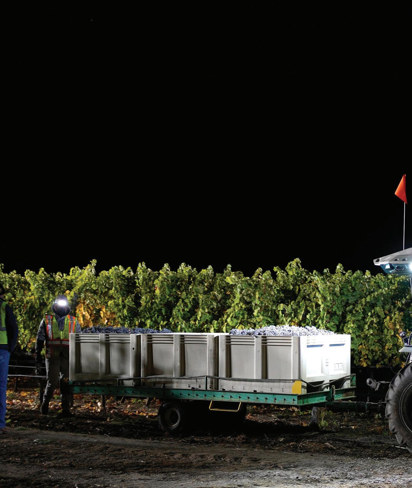
Here, an all-electric MK-V Monarch Tractor can be driven or operated autonomously with up to 14 hours of runtime and a swappable battery.
Tractor
Instead, they usually include simple plain bearings to provide guidance to the rod without significantly contributing to load-carrying capacity.
Ballscrew rod-type electric actuators more often replace fluid-power cylinders due to their similar form factor, force transmission, and mounting. Rod-type actuators output thrust or plunge in extension or retraction — a lot like fluidpower cylinders. So, they can be easy to retrofit into legacy machine designs.
High axial force and stiffness are other benefits … especially over short to moderate strokes. Plus, rod actuators support clevis, trunnion, or foot mounting just like fluid-power cylinders do. Plus, during the design-engineering
phase, their strokes are specified in comparable ways.
Many rod-style electric actuators are also IP-rated and sealed to satisfy the same requirements as fluid-power cylinders to withstand challenging environments.
To be clear, traditional carriagetype ballscrew actuators are applied in electrification efforts and even to replace fluid power. But more often they’re used in previously manual applications or in totally new designs needing accurate and repeatable positioning such as pickand-place tasks.
Out of all the pneumatic actuator types, rodless cylinders (complete with linear bearings to address
moment loads in X, Y, and Z) are most likely to be a competing technology to electromechanical solutions. They have higher power densities than sizeequivalent electric actuators so can output more force than comparable electric actuators. Plus, rodless pneumatic cylinders are extremely fast — capable of meters per second.
That said, compressed-air power characteristics mean upsizing pneumatic cylinders for high force generally diminishes their speed and vice versa.
Long strokes also diminishes cylinder top speed … though ballscrew whip imposes similar speed limits on extra-long axes.
Electromechanical designs (especially ballscrew-based actuation of linear axes)


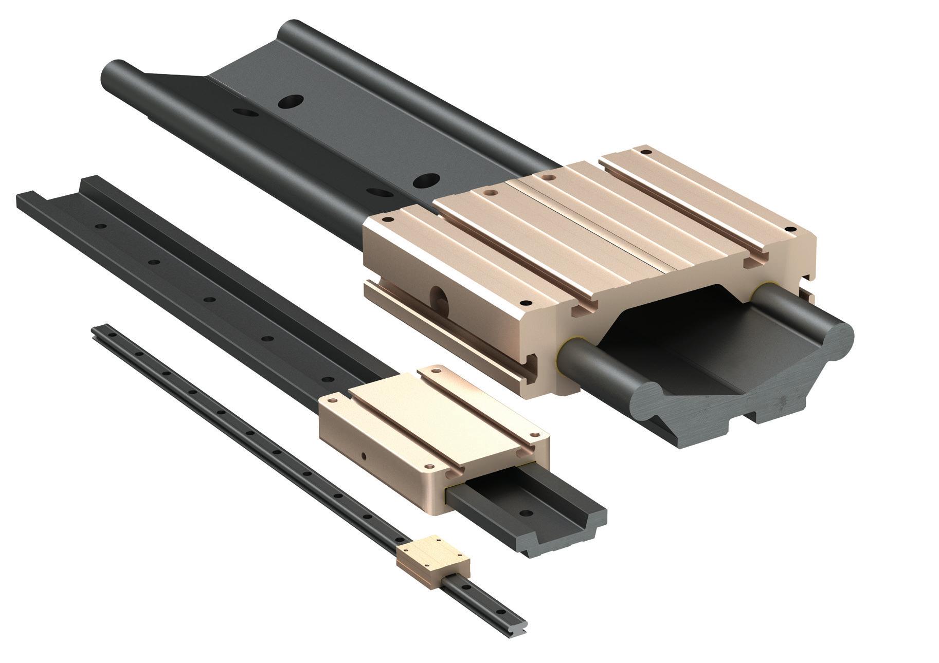


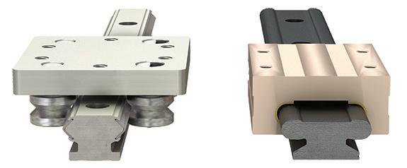
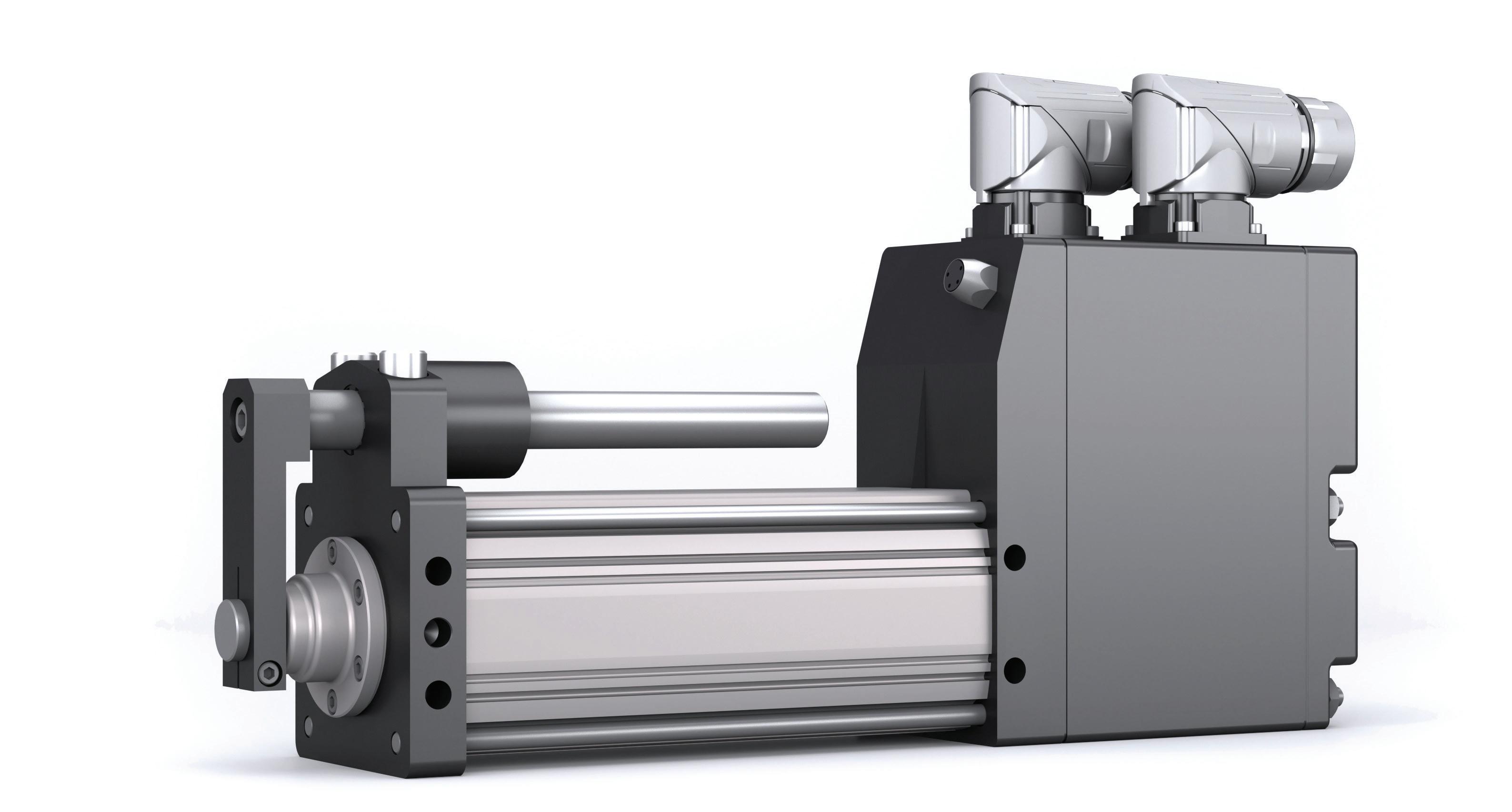
also offer the two benefits of efficiency and simple physical architecture. Pneumatic cylinder needs clean air via hose, compressor, valves, filter, regulator, lubricator, and fittings. Electromechanical designs only need an electrical supply and control. The efficiency differences can in many cases be considerable.
So how to know whether a ballscrewtype electric actuator (of any subtype) is the correct choice for a given electrification design? What if it’s more suitable to specify a roller-screw-based electric actuator — a component type we’ll cover in a moment?
An industry rule of thumb us that ballscrews generally compete against pneumatics and roller screws compete against hydraulics. But no such rule of thumb should ever be followed blindly — especially given the wide variety of adaptations of all four of these technologies.
What’s more, especially with electrification of very established designs such as farm equipment, quantification of the machine axes’ performance values may be needed.
Typically, an application’s required forces, speeds, and precision are more or less known. But sometimes full definition involves reverse engineering the function and feel of existing equipment in real-world environments.
Only after such investigations and analysis in simulation software can sizing and specification happen to ensure the electric drive, motor, and mechanical componentry satisfies power and speed requirements especially.
Or consider ballscrews’ somewhat rarer cousin — roller screws. Planetary, recirculating, differential, and inverted roller screws excel where high speeds and loads are present … even while maintaining efficiencies of 80% or better. These mechanical rotary-to-linear devices work in an increasing number of electromechanical actuators. Satellite roller-screw geometry especially includes far more internal contact between load-bearing subcomponents than their ballscrew cousins, and that boosts rigidity and dynamic load capacities. What’s more, fine pitches of their subcomponents’ grooves
or threads often impart unbeatable mechanical advantage … so less input torque is needed to move a given load. Roller screws often compete with ballscrews and fluid-power-based cylinders for linear motion. Forces are comparable to those of similarly sized hydraulics — typically from 20,000 lbf to 800,000 lbf depending on size and design — and high thrust capacity thanks to the numerous and relatively large (line) contacts between nut rollers and screw. In addition, actuators based on roller screws maintain efficiencies to 90% compared to hydraulic-cylinder efficiencies to 50% or so.
Speeds and accelerations are comparable to those of pneumatics … exceeding 40 in./sec and 3 g in some cases. Such output is possible because the load-carrying rollers in roller screws don’t contact one other. That’s unlike the balls in ballscrews that collide and strike recirculation end caps which in turn unwanted generates forces and heat. So even where the high forces of roller screws aren’t required, their high speeds and acceleration is useful: Roller
screws (instead of ballscrews) to replace pneumatics gives designs heightened ability to withstand continuous-duty and frequent cycling conditions.
Two drawbacks of roller screws include their higher cost (even to 100% more than comparably sized ballscrews) and their being less common than other technologies.
One final note about the motors of electrification. As covered in a recent Design World podcast at designworldonline.com/podcasts, one might assume that for battery-powered vehicles, dc-driven motors are the only viable option. In fact, power electronics and advanced control algorithms are now letting engineers use ac-based systems for mobile equipment. Such ac systems offer better controls and efficiencies than many dc systems.
The electric linear actuators (and other electromechanical solutions)
here need ruggedized and sealed housings to withstand the challenges of operating outdoors. As of now, most all actuators in these designs also have at their core a dc motor for easy integration into battery-powered and onboard power-generation systems. But change is coming.
Consider garbage-collection trucks driven slowly and subject to lots of stops. Regenerative braking (and the electric systems to leverage its benefits) is perfect here. Certain ac electricmotor systems on container handlers at shipping ports are another example. Instead of direct current, the drive motors on these vehicles might better employ permanent-magnet ac motors. In contrast with sinusoidal input to threephase ac motors, the motors accept the finessed square waves of pulse-width modulation adaptations generated by specialty inverters. Efficiency is highest when such drives feature semiconductors to optimize magnetic flux to the motor windings in realtime.
IGBT transistors dominate but siliconcarbide transistors for drive
switching could one day take over — especially for electrified off-highway equipment — because they’re slightly more efficient … by 5 to 10% or so. Even such tiny gains help a batterypowered vehicle. DW
“More nut-assemblyto-roller-screw contact equates to higher load capacity than ballscrews — as well as better rigidity and less deflection. Crowned threads (or grooves) renders efficiency about that of ballscrews.”


The margin for error in industrial maintenance is shrinking, with just a few minutes of equipment downtime costing companies tens of thousands of dollars. Manufacturers, processors and operators of complex systems are facing growing pressure to keep machinery running at optimal levels while simultaneously reducing operating costs. It's a balancing act, and
it has brought new urgency to tools that improve responsiveness, accelerate troubleshooting, and support better long-term decision-making. At the center of that evolution is diagnostic technology.
Fluid power systems in particular are experiencing a transformation. These systems, often the backbone of industrial machinery, rely on
components that must function within tight performance thresholds to maintain safety and reliability. When a hydraulic system fails, the consequences are rarely contained to a single machine. Ripple effects can disrupt entire production lines, delay delivery schedules and significantly impact a company's bottom line. This has made fast, data-driven problem

solving a key part of any modern maintenance strategy.
Traditional maintenance practices have typically relied on technician intuition alongside scheduled intervals and historical data. These methods can be and have been effective to an extent,
but they often fall short in accurately identifying the root cause when something goes wrong. Reactive maintenance, where components are repaired or replaced only after a failure has occurred, is still widespread despite its well-documented drawbacks: high emergency repair costs, increased downtime and potential safety risks.
This is where diagnostic tools provide a critical advantage. Rather than relying on guesswork or lengthy trial-and-error inspections, teams can use precise, real-time data to isolate faults faster and act with greater certainty. These tools don’t just help in the moment — they also enable longterm corrective actions that reduce the risk of repeated failures down the line.
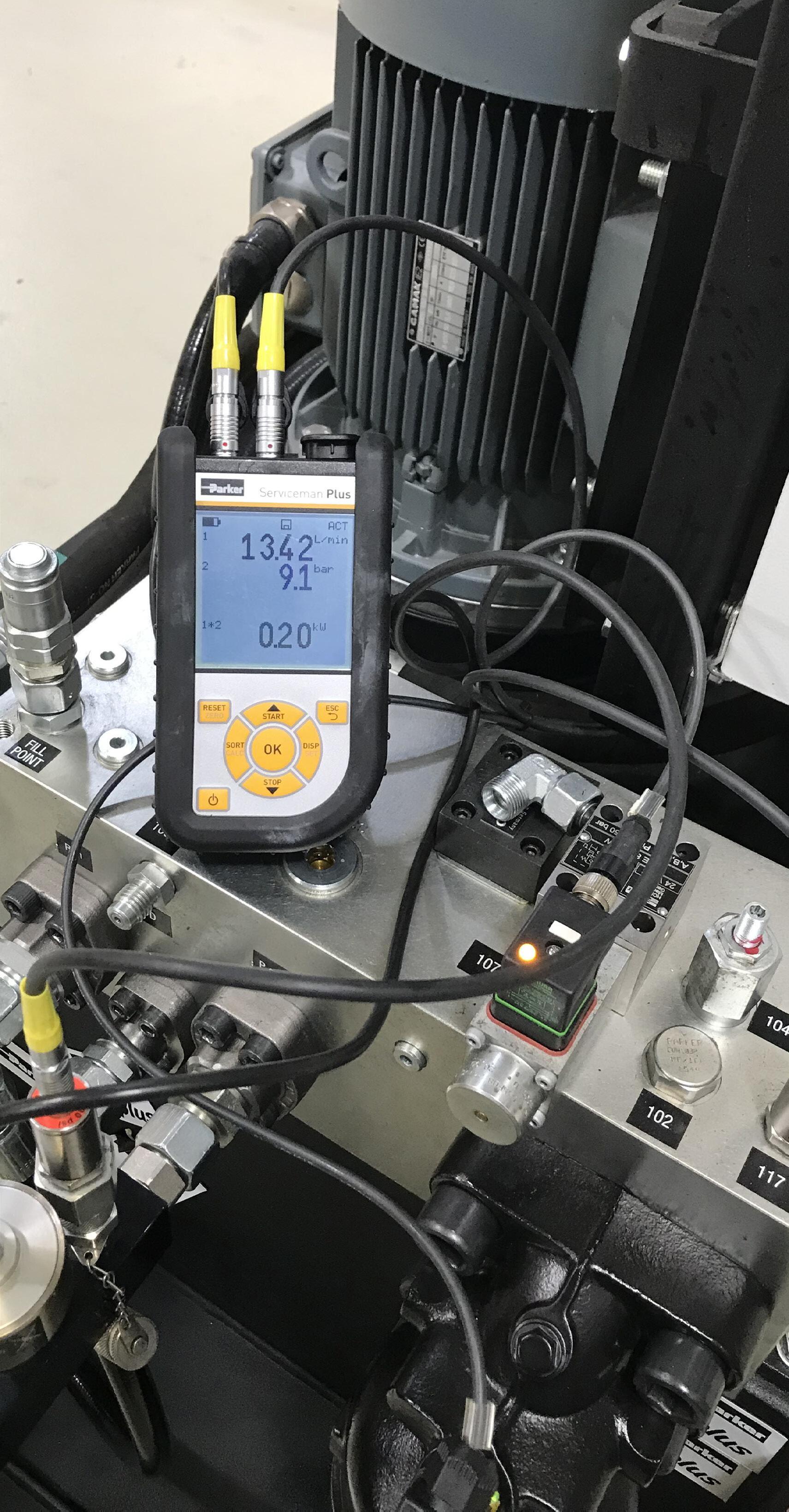
Smart diagnostics technology has emerged as a critical tool for identifying the root causes of performance issues and system failures. By monitoring key indicators such as pressure, temperature and flow, these systems provide immediate insight into the health and behavior of fluid power and hydraulic circuits.
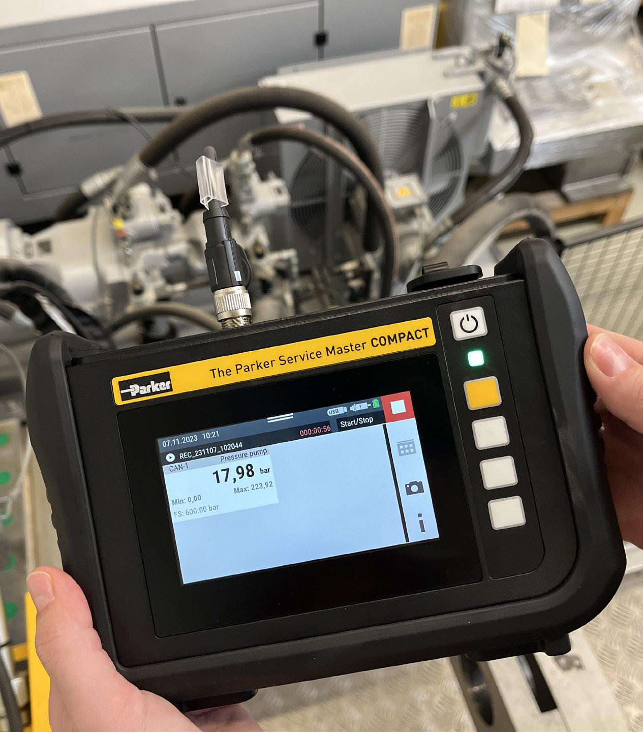
For example, Parker Hannifin's SensoControl diagnostic solutions enable technicians to capture dynamic measurements directly from hydraulic systems without disrupting operations. These measurements can then be analyzed to detect anomalies and pinpoint failure modes with speed and precision.
This visibility allows maintenance teams to isolate problems efficiently, validate assumptions, and implement data-backed solutions that address the real issue, not just the symptoms. Just as importantly, these diagnostics help ensure that corrective actions prevent the same failure from happening again.
The value of diagnostic tools lies not just in detecting a problem, but in equipping teams with clear, defensible data to act on. When sensor data is aggregated and analyzed, it helps teams confirm hypotheses, validate repair effectiveness, and design more reliable systems for the future.
Imagine a scenario where pressure fluctuations in a fluid power system’s hydraulic line are occurring more frequently than usual. Without diagnostic data, identifying the source might require days of disassembly, inspections and guesswork. With accurate sensor input, however, a technician can quickly verify if the issue is linked to valve performance, contamination, or some other factor, making the path to resolution faster and more effective.
In larger facilities, the ability to compare diagnostic trends across

machines or locations enables systemwide improvements. It also reduces the time spent on recurring issues by informing better training, design updates or maintenance scheduling.
Industry 4.0 has accelerated the push for integrated, real-time maintenance data. As more assets become digitally connected, teams expect faster answers, better insights and clearer paths to resolution. Diagnostic technologies support this shift, not only by predicting failure in advance, but by delivering the right data at the right time when issues arise.
These tools are often integrated into broader IIoT platforms, where their data can inform team discussions, support compliance reporting, or influence next-generation equipment design. Diagnostics, in this context, are not just repair tools. They’re decision tools.
Some companies are even using diagnostic data to enhance digital twins, testing how future system changes
might prevent a known issue from repeating. These lessons feed into smarter component selection, adjusted operating thresholds or revised specs.
Smart diagnostics aren't just theoretical — they’re actively transforming how companies troubleshoot, test and develop products across sectors. Below are several examples of how organizations are leveraging diagnostic tools in meaningful, measurable ways.
In one case, a customer was experiencing intermittent field failures within their hydraulic fluid power system and needed help identifying the root cause. By using Parker Service Master Plus to set up multiple pressure measurement locations throughout the system, they were able to monitor performance parameters in real time. Once specific pressure thresholds were hit, the system triggered data recording, allowing an analyst to run the simulation passively while attending to other tasks.
The collected data was later exported and analyzed, ultimately leading to the identification of a root cause and changes in system design to prevent future failures.
In another example, a customer used SensoControl to complement existing test equipment. While they already operated an industry-standard testing machine — calibrated annually — they leveraged SensoControl in between calibration cycles to validate measurement accuracy. When one of their clients requested testing with a proprietary fluid, which differed from the one in the main testing equipment, switching fluids in the machine would have been time-consuming and expensive. Instead, they installed a few supplemental components within the system and used SensoControl alongside the proprietary fluid. Although the new fluid changed the calculation ratios, combining data from both systems allowed them to deliver accurate, timely results without overhauling their core equipment.
Smart diagnostics also support innovation at the design level. One customer in the agricultural machinery market uses SensoControl in the early phases of new product development to help define performance limits and failure modes. By capturing precise measurement data during validation tests, the engineering team can refine technical specifications
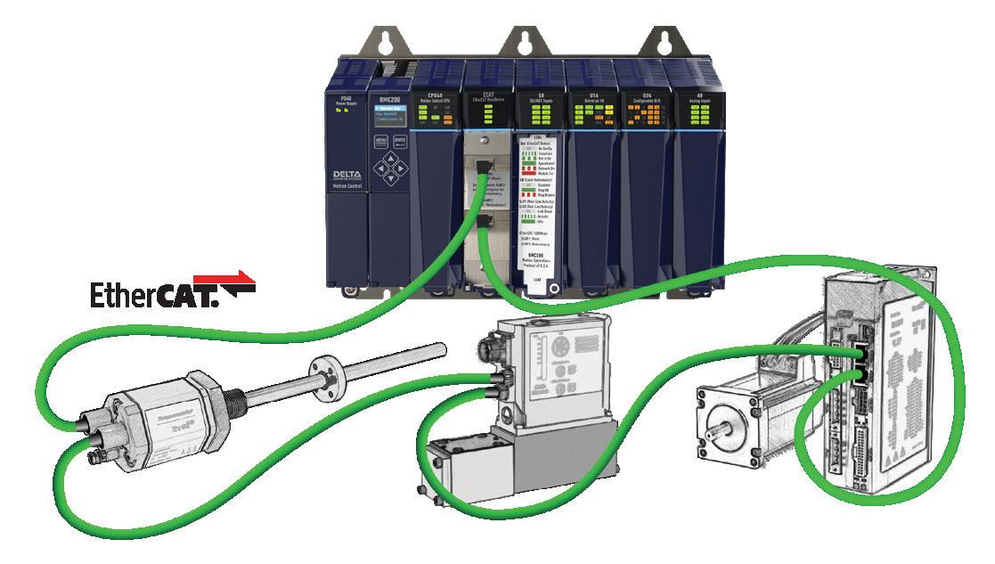
axis or fifty. Servo hydraulic or servo electric. Position, velocity, or force control. Direct connection or through EtherCAT.

and inform future design iterations. This approach results in better, more reliable products and fewer redesign loops down the road.
These are not isolated examples. Across industries such as automotive manufacturing, aerospace, material handling and heavy equipment, diagnostic technologies are helping organizations pinpoint issues faster and lower operating costs in hydraulic and fluid power applications.
Maintenance budgets are no longer just about labor and parts. They're increasingly shaped by how quickly teams can isolate problems, how accurately they can fix them, and how confidently they can prevent them from happening again.
By using smart diagnostics to guide troubleshooting, organizations can reduce costly delays and develop better long-term strategies. Instead of reacting blindly or over-maintaining systems, they can allocate resources more precisely and with greater confidence.
This approach doesn’t eliminate the need for hands-on expertise; rather, it enhances it. Technicians are empowered with the tools and data they need to be more effective. Meanwhile, management gains a clearer view of recurring issues, repair timelines and system-wide performance.
The adoption of smart diagnostics is accelerating, driven by the daily need to solve problems faster and smarter. As fluid power systems become more complex and uptime becomes more critical, maintenance teams will increasingly depend on diagnostics that deliver clarity in moments of uncertainty.
Smart diagnostics are not a silver bullet, but they are an essential part of a modern maintenance strategy. By capturing, analyzing, and acting on equipment data, companies can unlock new levels of performance and bring greater stability to their operations and their budgets.
In a time when every dollar counts and every minute matters, tools that guide smarter response and support lasting system improvements aren’t just helpful. They’re essential. DW

According to Siemens report The true cost of downtime, the annual cost of an idle production line at a major automotive facility has surged to $695 million — one and a half times higher than five years ago. In heavy industry, downtime now costs $59 million annually, a 1.6-fold increase since 2019. While bearing failures are relatively rare, improper lubrication remains a key contributor. Choosing between grease and oil isn't straightforward — it depends on factors such as speed, load, temperature, orientation, and contamination. Here, Chris Johnson, managing director of bearing specialist SMB Bearings, explores the advantages and limitations of each lubrication method.
These rising costs underscore just how critical it is to prevent avoidable equipment failures — but how often do production managers consider the critical role of industrial bearings in ensuring equipment longevity?
When applying industrial bearings, few choices are as important as the choice between grease and oil lubrication. Grease and oil share the same fundamental purpose, and each play an essential role in reducing friction, minimizing wear, and extending bearing life. That said, the conditions
in which they operate best are very different.
Put simply, making the wrong bearing lubrication choice can lead to overheating, premature failure, or unplanned downtime. To avoid these consequences, let’s look at how production managers can choose the best lubricant — and avoid the cost of equipment downtime.
Where grease excels
Grease has a thicker consistency than oil. It is usually a base oil suspended in
a soap-like thickener, which helps it stay in place more easily — especially in vertically mounted or hard-to-reach locations.
These characteristics make grease ideal for applications like electric motors, conveyor systems, or food processing equipment where protection from washdown or particles is essential. Grease also acts as a sealant, helping to keep out dirt, moisture, and other contaminants.
It is typically easier to apply and less prone to leakage, which makes it a cost-
effective solution for sealed or shielded bearings that aren’t regularly maintained. Grease is often the preferred choice in applications that require simplicity, longer service intervals, or operate in environments where lubricant retention would otherwise be a challenge.
However, grease also has its limitations. It doesn’t dissipate heat as efficiently as oil and can break down faster in high-speed or hightemperature environments. In such cases, excessive heat can cause the thickener to degrade, which reduces lubrication effectiveness and potentially damages the bearing.
Oil is often favored in very highspeed or low torque applications where better cooling and continuous circulation are needed. Unlike grease, oil can be pumped, filtered and monitored as part of a closed lubrication system — which allows contaminants to be removed and fresh lubricant to be supplied continuously.
Typical examples include gearboxes, machine tools, and high-speed spindles. In these cases, the superior heat transfer properties of oil reduces the risk of thermal damage and prolong bearing life. Oil also provides lower friction in many situations, making it well-suited to precision applications that demand tight tolerances and consistent performance.
That said, oil systems are more complex and require careful design. They need pumps, reservoirs, filtration units, and regular monitoring. Some applications require a continuous oil mist or oil spray — all of which add to maintenance requirements and cost. They’re also less effective in vertical or exposed environments where leakage or oil migration can become problematic.
Several operating parameters should guide the decision between grease and oil lubrication, each with a direct impact
on bearing performance. Speed is one of the most critical considerations — as rotational speed increases, so does friction and heat. In many high-speed applications, oil is preferred for its ability to circulate and dissipate heat more effectively than grease.
Temperature is another key factor. In environments where bearings are exposed to elevated operating or ambient temperatures, oil typically provides better thermal stability and cooling capacity with much less resistance than high temperatures greases.
Heavily loaded systems may benefit from oil’s superior film strength and flow characteristics, though grease formulations with extreme pressure additives can also perform well in lowspeed, high-load conditions.
In environments where contamination is a concern — such as dusty, wet, or chemically aggressive settings — grease tends to be the better option, as its consistency helps seal out harmful debris and moisture.
Finally, maintenance accessibility must be considered. In applications where regular relubrication is difficult or
impractical, sealed bearings pre-filled with grease offer a more reliable and maintenance-free solution.
Ultimately, the choice between grease and oil comes down to balancing performance needs with practical constraints. Grease offers simplicity, sealing, and lower maintenance — ideal for many standard industrial and automotive applications. Oil, on the other hand, delivers superior cooling and lubrication under extreme conditions but requires a more involved setup and monitoring process.
By carefully assessing the demands of the application and understanding the strengths and limitations of each lubrication type — engineers and maintenance teams can make informed decisions that improve bearing life, reduce downtime, and optimize operational efficiency. DW

October 2025
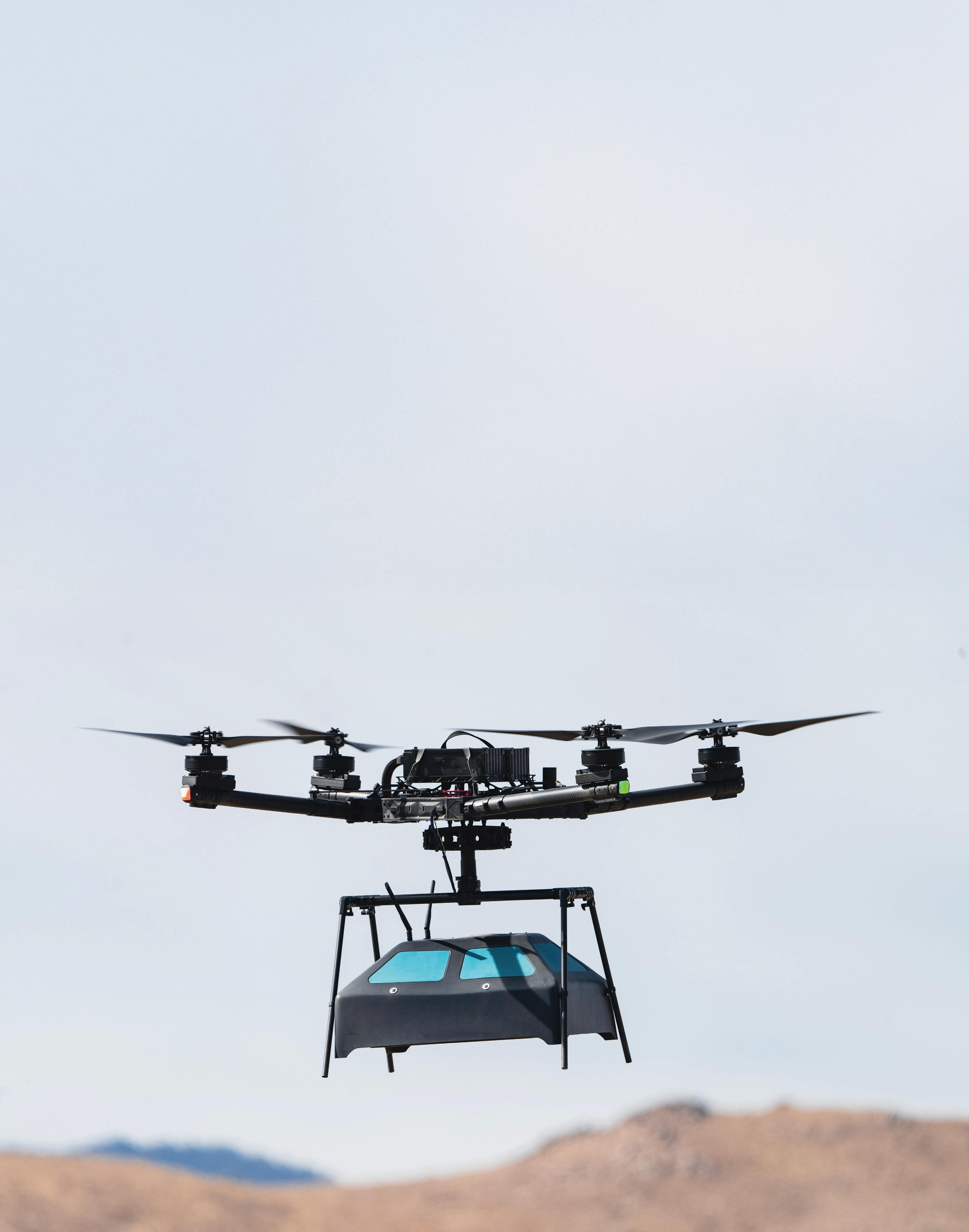
Millions of landmines remain undetected in active and former conflict areas. Harsh Zala and his team at Aerobotics7 have built an AI-enabled solution to detect these threats and save lives.
RACHAEL PASINI EDITOR-IN-CHIEF

Millions of landmines remain undetected in active and former conflict areas. Harsh Zala and his team at Aerobotics7 have built an AI-enabled solution to detect these threats and save lives.
When people think about landmine detection, they might envision soldiers sweeping metal detectors across battle-ridden terrain — a painstakingly slow and dangerous process that has remained mostly unchanged for decades. Though other methods using vehicles and technology exist, they have varying efficacy and still pose significant dangers to operators.
Harshwardhan Zala, founder of Aerobotics7, has a new demining solution with a drone-mounted radar system that can detect buried threats 600 times faster than traditional methods while achieving 96% accuracy on nonmetallic explosives.
The engineering challenge Zala tackles stems from a fundamental shift in explosive device construction. While traditional metal detectors excel at finding metallic components, modern threats increasingly rely on plastic casings and minimal metal signatures, making them nearly invisible to conventional detection methods.
The consequences of not detecting such threats extend beyond the battlefield, taking civilian lives and damaging communities and economies struggling to recover from war.
“Companies in aerospace and defense have been so focused on how we provide the best capabilities when conflicts happen, whether it’s preventing war or winning or attacking or better defense, but they are not incentivized for what happens after these conflicts are ended, to the communities, to the countries, and the
industries being damaged,” said Zala. Determined to work toward his vision of “a world without landmines,” Zala and his team built an innovative system, the Eagle A7, that has caught the attention of governments worldwide.
The Eagle A7 system is a custom radar design that diverges significantly from traditional groundpenetrating radar approaches. While conventional systems are bistatic, with one transmitter and one receiver, Zala's team developed an antenna array architecture.
“Our radar system is an antenna array which creates a 3D point cloud under the surface of the Earth with a broader spectrum of frequency range, from radio waves or RF range to microwave,” Zala said.
This approach enables the system to achieve detection depths of up to three meters from ground level as the drone operates one meter above the surface and generates high-resolution subsurface mapping.
The system includes electro-optical sensors for RGB imaging, thermal cameras for infrared detection, and LiDAR for terrain mapping. This multisensor approach enables sensor fusion, which feeds real-time data to the AI model.
Traditional detection systems often rely on basic threshold logic: signals

The Eagle A7 is an AI-enabled drone with a custom radar system that detects threats three meters below the Earth’s surface. Aerobotics7

Harwin’s connector products are proven to perform in extreme conditions, with shock, vibration and temperature range rigorously tested.
WITH OUR QUALITY, SERVICE, SUPPORT, AND HIGHLY RELIABLE PRODUCTS, YOU CAN DEPEND ON HARWIN.


When product performance matters, it's critical to select a coating partner who can solve your tough engineering problems - eliminate friction, sticking, abrasion and more. With Orion Industries, you get peace of mind that your products and parts will be coated correctly the first time, every time
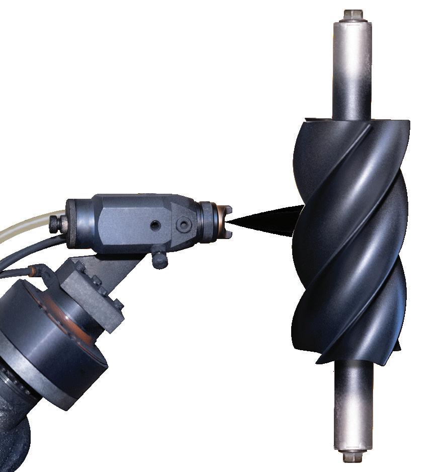


above a certain level indicate potential threats, while those below suggest clear terrain. Zala’s approach abandons this binary method in favor of a multimodel AI architecture that analyzes specific signature patterns.
“We're going after a very specific signature pattern that we collect for each of these target types, and our AI model is trained around that,” said Zala. “We have several layers within our AI model. We’ve built a multimodel AI suite which doesn’t operate in a single CNN [convolutional neural network] architecture, for example. Rather, multiple architectures are built in, which helps us first do sensor fusion and then run the AI model specifically around that.”
The system processes sensor data in real-time, building a threat library that adapts to new explosive types as they arise. This adaptive capability addresses a key limitation of static detection systems that struggle with evolving threat signatures.
Zala’s team developed their current AI model through an unconventional path that began in 2015, well before the current AI adoption trends emerged. Working initially without formal engineering education — Zala is mainly self-taught, having learned programming languages and electronics through research papers downloaded at internet cafes in his small hometown in India — he built early prototypes using Ardupilot flight controllers for quadcopter designs.
The sophisticated sensor package and onboard computing power create significant electrical demands. The Eagle A7 system achieves approximately 22 minutes of flight time using two heavy lithium-polymer batteries, which is substantially less flight time than typical drone operations.

“It takes a lot of power — the radar system itself and our computer. Our next milestone is, how can we reduce the power requirements? The power is one of the challenges that we are trying to solve right now,” said Zala.
Despite the power limitations, Zala claims the system’s speed advantages compensate for shorter flight durations. According to his research data, traditional demining operations require approximately one hour to detect and clear a single square meter of terrain. In comparison, he states the Eagle A7 system covers the same area in two to five seconds, providing detection data directly to ground-based deminers.
Autonomous navigation enables pattern recognition
The Eagle A7 incorporates autonomous navigation capabilities that allow single-operator control while the drone
executes predetermined search patterns. The system creates its own navigation protocols and flight maneuvers based on terrain characteristics and mission requirements.
“The great thing about our software is not only a single operator interface, but it has autonomous navigation and autonomy built in. So, we create our own navigation inside that, and the drone flies and creates maneuvers around where it’s most applicable or needed, and runs patterns accordingly,” Zala said.
Operators can select target areas remotely, with the drone executing autonomous scanning while providing real-time threat identification through a ground control interface.
Rather than developing proprietary drone hardware, Aerobotics7 focused its engineering resources on the detection system itself. This strategic decision allows integration with existing drone platforms
that customers already operate, reducing adoption barriers and enabling scalability.
"Building a drone is reinventing the wheel at this point in time, and if we want to have the scalable effect we want, we want to join hands with someone who's been in this, and our customers are already using their technologies," Zala said.
The modular approach extends beyond aerial platforms. Zala said he can install the sensor package on uncrewed ground vehicles, tractors, and autonomous underwater vehicles for maritime mine detection.
Testing and validation results pique government interest
Aerobotics7 has achieved Technology Readiness Level 7 (TRL-7) by demonstrating its capabilities in an operational environment with military partners. Testing included both replica The AI model collects and analyzes real-time
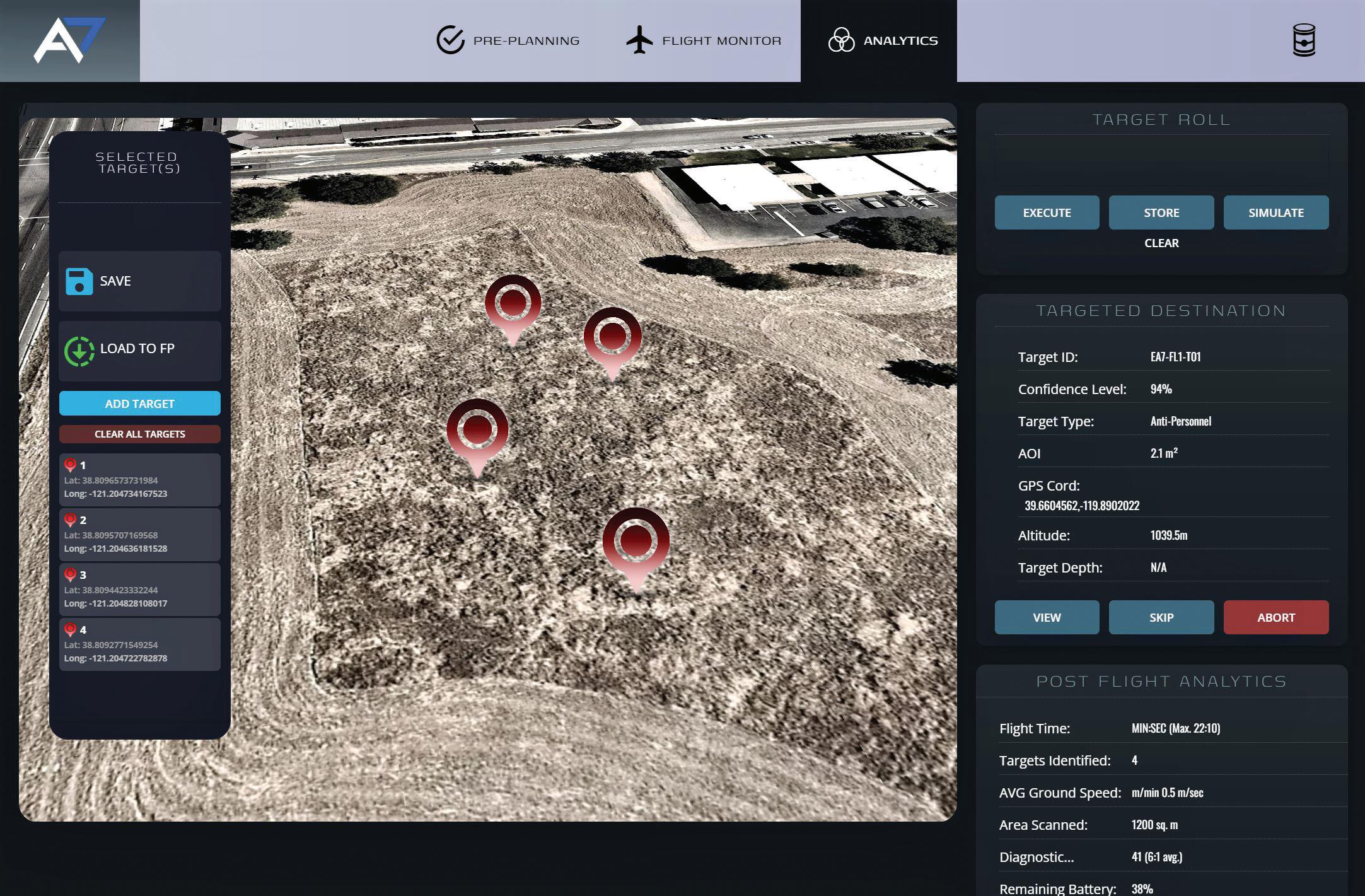

Rotor Clip Wave Springs are engineered to save space and weight by reducing spring heights up to 50%. Our experienced engineering team is ready to assist you in specifying a standard spring or developing a custom design in the material and size you require. From prototype to production, we'll provide you with the perfect spring solution for your application.


landmines and actual explosive devices (some with charges removed).
The company’s claimed 96% accuracy rate specifically applies to nonmetallic threats found in Ukraine, piquing the interest of Ukraine’s Ministry of Defense. However, Zala notes that detection performance varies based on environmental characteristics, soil conditions, and threat types.
The engineering motivation behind Aerobotics7’s development stems from the massive scale of global landmine contamination. Zala cites estimates of more than 100 million active landmines buried across 60-plus countries, with traditional clearance methods proving inadequate for the scope of contamination.
Ukraine’s situation exemplifies the challenge: Zala states that 25% of the country’s territory is contaminated or suspected of being contaminated, with half of that area consisting of farmland. According to Zala’s Ukrainian partners, clearance efforts have addressed less than 0.2% of contaminated areas despite spending more than $1 billion in the past few years.
“Compare that with our technology, or what we are able to achieve right now ... it takes us two to five seconds to cover a square meter of area, sense, detect,
and provide the data to the deminer,” Zala said. “So that saves a lot of effort, a lot of time for these deminers, almost 600 times faster.”
The technology addresses both postconflict cleanup and active battlefield scenarios. Zala notes that more than half of military casualties result from IEDs (improvised explosive devices) and buried threats rather than direct combat engagement, creating operational demand beyond humanitarian demining applications.
Aerobotics7 received recognition as the winner of the 2024 Kluz Prize for PeaceTech, an award that highlights what founder Artur Kluz terms “triple-use” technology companies. This concept extends beyond traditional dual-use (defense and commercial) applications to include peace technology use cases.
“Triple-use is very interesting. It’s companies that are doing applications and supporting defense use cases, using their technology as well as commercial ones. But on top of that, they also have a really strong use case on social impact PeaceTech as well,” Zala said.
This approach enables defense contractors to address postconflict remediation while maintaining commercial viability and defense capabilities, thereby encouraging broader industry
With an antenna array architecture and multiple sensors, the system creates high-resolution subsurface mapping and detects threats with 96% accuracy. . Aerobotics7
participation in peace technology development.
Engineering a path forward
Looking ahead, Aerobotics7's primary engineering challenges center on power optimization to extend flight duration and continued refinement of the AI model for emerging threat types. The company plans to deploy multiple drones simultaneously to cover larger areas more efficiently, following robotics trends toward swarm deployment rather than single large-system approaches.
The modular sensor architecture positions the technology for integration across multiple platform types, potentially enabling coordinated air, ground, and maritime detection operations using the same core detection algorithms and signature libraries.
For Zala, whose informal engineering education path began with dismantling electronics in his grandfather's workshop and progressed through self-directed research and tinkering, the technical challenges represent a pathway toward what he describes as "a world without landmines."
"The only thing that will keep me going is the purpose of why I started this," he said. "How can we utilize the power of technology to safeguard these countries and safeguard lives at a massive scale?" AD
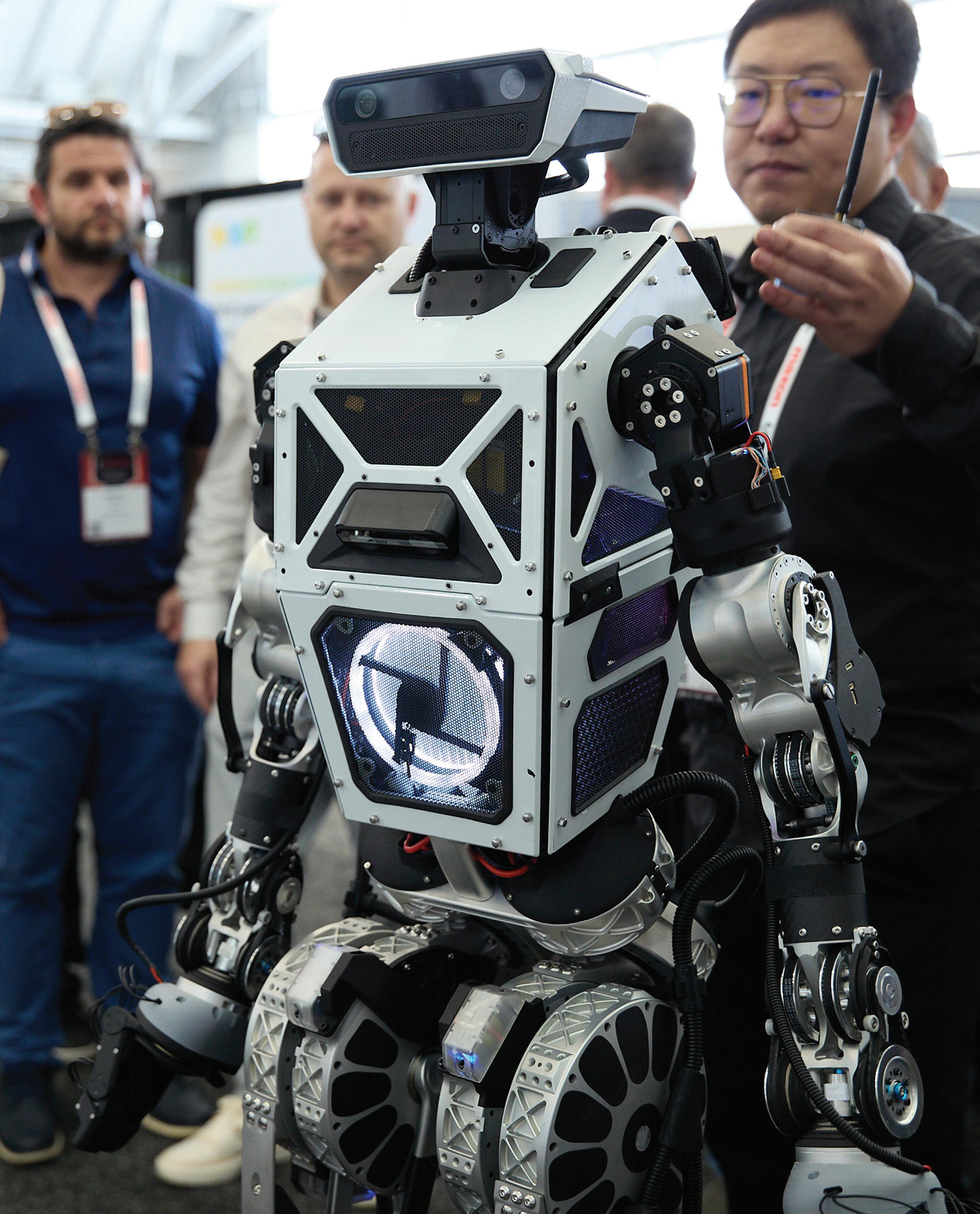

Hospitals are under increasing pressure to do more with fewer resources. Both inside the operating room and in the halls of hospitals, robotics could reduce this pressure and help hospitals make the most of their staffs.
By 2030, there will be a global healthcare worker shortage of at least 10 million workers, predicted the McKinsey Health Institute. Healthcare providers are struggling to find people to do repetitive, laborious tasks that keep hospitals running, Ting Ming Ling, the founder and CEO of OTSAW, told The Robot Report
This workforce shortage exists at every level of healthcare. According to the Association of American Medical Colleges (AAMC), the U.S. will be short between 13,500 and 86,000 physicians by 2036.
At the same time, cuts in federal
support are leaving hospitals, particularly those in rural areas, with tighter budgets.
A report from the National Rural Health Association and Manatt Health found that rural hospitals will lose 21 cents out of every dollar they receive from Medicaid due to recent federal cutbacks. Ling, who has led OTSAW to deploy logistics robots in hospitals, and Dr. Sudhir Srivastava, founder, chairman, and CEO at SS Innovations International Inc., shared their insights on how robotics can help hospitals tackle these challenges.
In recent years, surgical robotics adoption has increased, more surgical providers have entered the field, and costs have started to come down, according to Srivastava.
“Initially, Intuitive Surgical was dominating — currently, it has over 10,000 systems,” he said. “Now there are other companies in the pipeline, including SS Innovations, Medtronic, Cambridge Medical Robotics, Moon Surgical, Distalmotion, and others that are in various stages of either development or the approval processes.”
With a more competitive field, Srivastava said he expects costs to come down, making surgical robotic systems easier to deploy. “As new technologies are introduced, the features are becoming increasingly advanced, particularly with the integration of artificial intelligence and machine learning,” he said.
In addition, advances in telesurgery, present many new opportunities, said Srivastava.

“At SS Innovations, we have found that surgeons who are new to the robotic system can be guided by the expert surgeons, sitting wherever, using their highspeed connectivity and the technology that we have developed,” he said. “There is also an option in telesurgery where the expert surgeon can take over and finish the procedure if there is any challenge.”
“This is drastically changing the scene in terms of access for patients to whom surgical expertise would otherwise not be available,” Srivastava noted. “It also builds confidence in the operating teams because they can learn remotely as the surgeries are taking place and try again under supervision through teleproctoring.”
COVID brought robots into hospitals, and they’re here to stay
While surgical robots have pushed new bounds in recent years, the operating room isn’t the only place embracing new technology.
Round, Flat, Vee and Poly-V belts and pulleys

We use 100% virgin urethane (no regrind waste). Makes stronger, longer lasting belts.
« Abuse Resistant Belts work where others fail.
« Super Strong Joints are virtually unbreakable.
« High Tension Belts move heavier loads.
« HEHT black belts double capacity.
« Low cost, highly efficient, elastic flat belts.
l High precision. Reasonable price.
l Easy to install. Zero downtime.
Round, Flat, Vee and Poly-V Belts and Pulleys

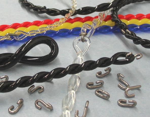


According to Ling, COVID-19 was a major turning point for implementing logistics robots in hospitals. Many people left the healthcare industry, and at the same time, it was risky for the staffers who remained to constantly be exposed to airborne diseases.
Surgical robots offer precision and ergonomics, but cost is still a challenge. SS Innovations
“The fatigue definitely is a big factor. We saw lots of attrition, people leaving the healthcare sector due to the high risk and fatigue,” Ling said. “There were so many things going on, and now you suddenly see that there’s a vacuum or a lack of supply of this workforce.”
Now that COVID-19 has passed, interest in automation hasn’t slowed, he added. Unlike other robotics sectors, which saw a bump in sales around the pandemic but have since seen those sales slow, healthcare is just getting started, asserted Ling. And workforce shortages are only making logistics robots more important.
“From a U.S. perspective, it’s really exciting, because people are just opening up. A lot of budget or money was going to the infrastructure of hospitals during those years of COVID,”

Ling said. “Right after COVID, they were still busy trying to get [hospitals] all ready in case another pandemic came. Now that all this has been settled, you look at the logistics sites and the infrastructure of the logistics.”
Logistics robots require thoughtful workflow changes
Ling said the key to deploying logistics robotics into hospitals is not to look at automation as just replacement for human workers.








“A modern U.S. hospital is a very complicated operation,” he said.
“I would say it’s one of the most complicated operations in the world from a business perspective, because in the hospital you have so many various departments, and they need to intertwine and interlock and work with one another.”
This means that if one department drops the ball, this could delay care for a patient. Ling found that each department in a hospital often worked


Position, angle and speed measurement
Contactless, no wear and maintenance-free High positioning accuracy and mounting tolerances
Linear and rotary solutions
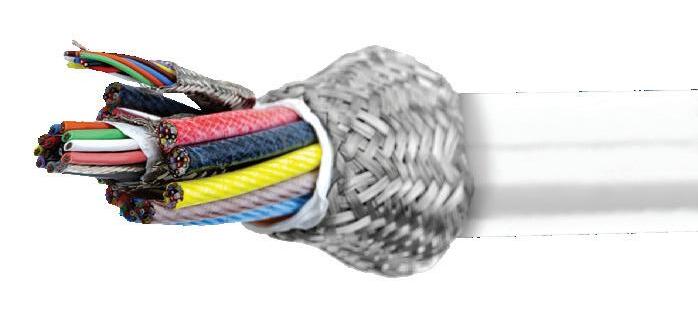




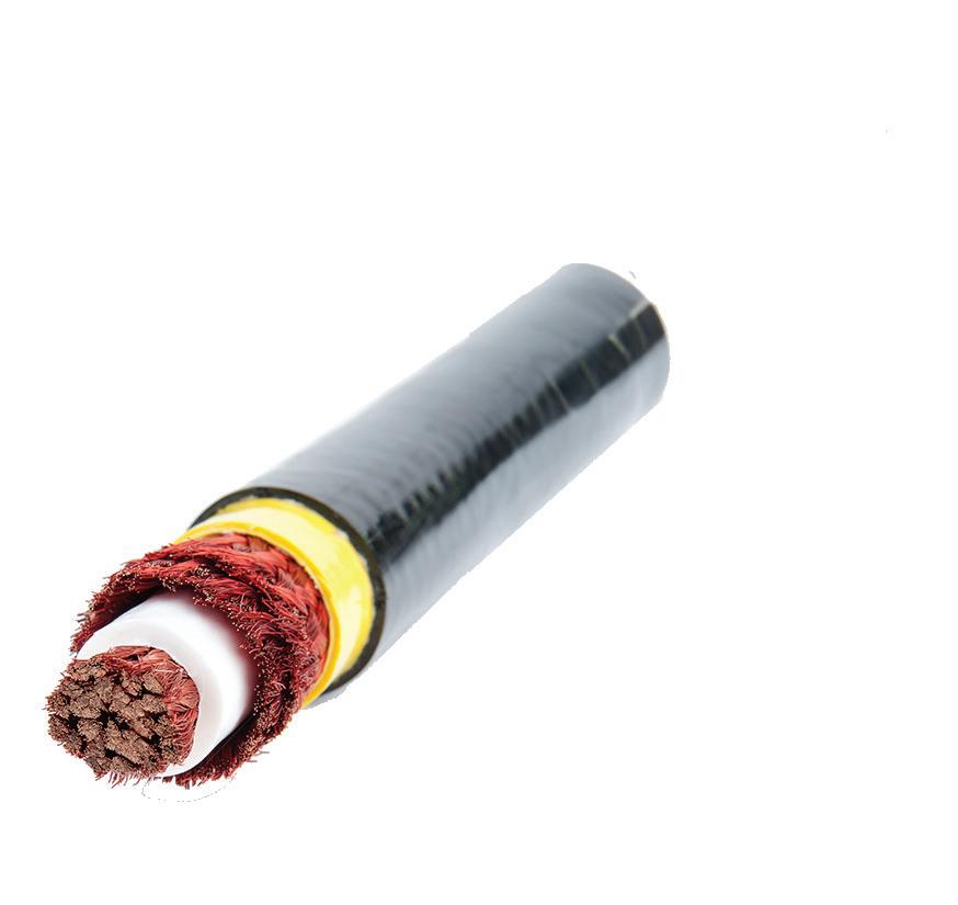


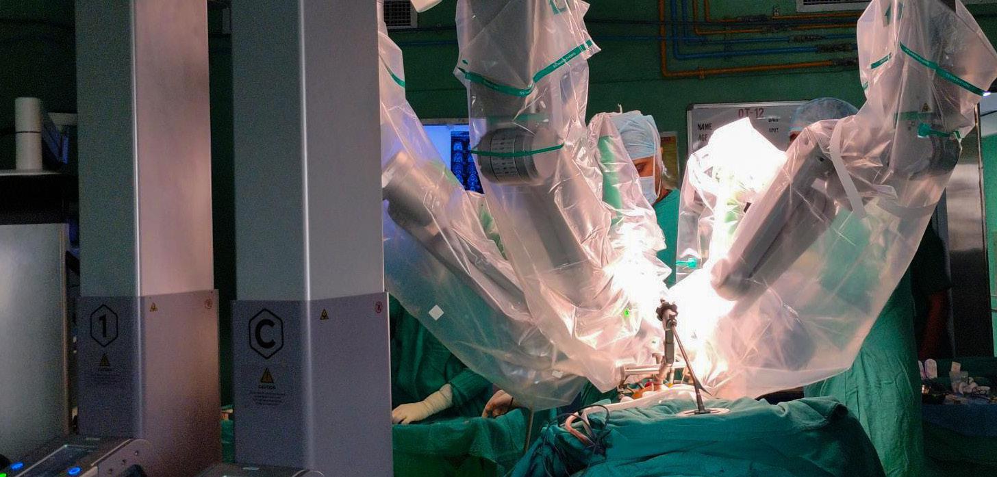
on its own, resulting in overlapping staffing in each department.
When OTSAW deploys robots, it works across departments to turn transportation into a horizontal function. This allows the hospital to take multiple people in charge of transportation in each department and upskill them to a different task.
“Then you can repurpose and upskill the human to do something else nearer to the bedside, where they can add more value and show more care and concern to the patient,” Ling said. “I think we have to rethink how we use that manpower wisely; that’s something I feel very strongly about. We need to educate. We need to look at it from a more constructive angle.”
Both Ling and Srivastava highlighted the importance of bringing costs down to make robotics more accessible.
Ling said OTSAW has been focusing on producing robots at scale, which can help bring costs down. The Singaporebased company also offers a leasing model for its robots to further reduce barriers to adoption.
“You don’t need to buy it. You just lease it from us. And from the first day you save money,” said Ling. “We will invest. We put in the infrastructure, we put in the robot, we will train your people, and we will put in the technicians there to maintain the fleet of robots.”
Ling asserted that hospitals can save money quickly when implementing
logistics robots. OTSAW customers see a return on investment (ROI) in just 30 days, and they can save $2.6 million a year in operating costs, he said.
Bringing down the costs of surgical robots is much trickier, and something that Gurugram, India-based SS Innovations has worked hard to do.
“SS Innovations has created a very advanced and different type of robotic system, which ultimately is very costeffective compared to others,” Srivastava said. “Since the cost factor has been addressed, it will lead to much greater penetration, ultimately translating into access by the patients.”
However, as SS Innovations grows, the company has faced its own workforce challenges.
“With so many companies entering the space, recruiting experienced robotics engineers has become increasingly difficult. I believe this will remain a challenge as competition grows,” Srivastava said. “However, with education and robotic institutes where engineers can be trained from the beginning, the industry can face these challenges head-on. This would make finding talent much easier, and robotic technologies could continue to evolve.”
While there are many opportunities for robotics to improve healthcare, humans will still be at the center of it all. When it comes to surgical robotics, Srivastava said surgeons will always be involved to some degree for the foreseeable future.
Telesurgery and robot-assisted procedures promise to democratize care, one goal of this SS Innovations demo of head and neck surgery in Delhi. SS Innovations
“Even when semi-automation and automation come into practice, the surgeon must remain actively involved,” Srivastava said. “We cannot leave everything to the machine without compromising the safety of the patient due to the complexity of variable anatomy and different findings that may be unanticipated.”
“I think, in the next five to 10 years, as the machines become more available, it will upscale surgeons’ skill levels and enhance their surgical careers,” he added. “Moreover, using robotic surgery with features like magnified 3D vision, filtered cameras, precise translation of patient emotions, and a lot of the procedures that otherwise are very challenging will become accessible to patients.”
On the logistics side, Ling said he believes robots will ultimately free up hospital workers to spend more face time with patients, and less time doing repetitive manual tasks.
“There is so much that we can do to empower and uplift and upskill our people. I think more should be said about that,” Ling said. “If we just talk about the technology and the world without the human, then the equation isn’t correct, and that puts fear into humans today. We need to be sensitive, we need to be inclusive, we need to put that human in the equation.” RR

KHK USA offers the broadest selection of stock metric gearing in North America. Designed for use in industrial automation applications, conveyor systems, packaging equipment, robotics, and general machinery applications, KHK’s selection of spur gears, helical gears, internal ring gears, gear racks, bevel gears, screw gears, worms & wormwheels, ratchets & pawls, gear couplings, right-angle gearboxes, and gear lubrication systems are available in various materials and sizes. KHK’s website offers free 3D CAD models for all gear products, complete product specifications, and 24/7 shopping. With KHK USA, stock gears are delivered from stock, with no minimum order or credit card surcharges.
KHK USA Inc.
259 Elm Place, Mineola NY 11501 516-248-3850
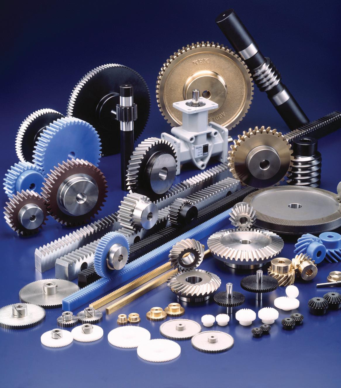
Why accept a standard product for your custom application? NEWT is committed to being the premier manufacturer of choice for customers requiring specialty wire, cable and extruded tubing to meet existing and emerging worldwide markets. Our custom products and solutions are not only engineered to the exacting specifications of our customers, but designed to perform under the harsh conditions of today’s advanced manufacturing processes. Cables we specialize in are LITZ, multi-conductor cables, hybrid configurations, coaxial, twin axial, miniature and micro-miniature coaxial cables, ultra flexible, high flex life, low/high temperature cables, braids, and a variety of proprietary cable designs. Contact us today and let us help you dream beyond today’s technology and achieve the impossible.


PUBLICATION TITLE PUBLICATION NO. FILING DATE Design World 025-146 9/22/25
ISSUE FREQUENCY NO. OF ISSUES PUBLISHED ANNUALLY ANNUAL SUBSCRIPTION PRICE Monthly 12 USA $125, Canada/Intl $195
COMPLETE MAILING ADDRESS OF KNOWN OFFICE OF PUBLICATION
WTWH Media, 1111 Superior Ave, Suite 1120, Cleveland, OH 44114
COMPLETE MAILING ADDRESS OF PUBLISHER’S HEADQUARTERS
WTWH Media, 1111 Superior Ave, Suite 1120, Cleveland, OH 44114
FULL NAMES AND COMPLETE MAILING ADDRESSES OF PUBLISHER, EDITOR, AND MANAGING EDITOR
PUBLISHER: Courtney Nagle, WTWH Media, 1111 Superior Ave, Suite 1120, Cleveland, OH 44114
EDITOR: Rachael Pasini, WTWH Media, 1111 Superior Ave, Suite 1120, Cleveland, OH 44114
MANAGING EDITOR: Mike Santora, WTWH Media, 1111 Superior Ave, Suite 1120, Cleveland, OH 44114
OWNER COMPLETE MAILING ADDRESS
WTWH Media, LLC, 1111 Superior Ave, Suite 1120, Cleveland, OH 44114
Mountaingate Capital, 1225 17th St, Suite 2575, Denver, CO 80202
KNOWN BONDHOLDERS, MORTGAGEES, AND OTHER SECURITY HOLDERS
OF TOTAL AMOUNT OF BONDS, MORTGAGES, OR OTHER
OR HOLDING
Ryan Ashdown rashdown@wtwhmedia.com 216.316.6691
Jami Brownlee jbrownlee@wtwhmedia.com
POSTMASTER: Send address changes to: Design World, 1111 Superior Ave., Suite 1120, Cleveland, OH 44114 STATEMENT OF OWNERSHIP, MANAGEMENT AND CIRCULATION
DESIGN WORLD does not pass judgment on subjects of controversy nor enter into dispute with or between any individuals or organizations. DESIGN WORLD is also an independent forum for the expression of opinions relevant to industry issues. Letters to the editor and by-lined articles express the views of the author and not necessarily of the publisher or the publication. Every effort is made to provide accurate information; however, publisher assumes no responsibility for accuracy of submitted advertising and editorial information. Non-commissioned articles and news releases cannot be acknowledged. Unsolicited materials cannot be returned nor will this organization assume responsibility for their care.
DESIGN WORLD does not endorse any products, programs or services of advertisers or editorial contributors. Copyright © 2025 by WTWH Media, LLC. No part of this publication may be reproduced in any form or by any means, electronic or mechanical, or by recording, or by any information storage or retrieval system, without written permission from the publisher.
Subscription
By Mark Jones


The knife drawer in the borrowed vacation house didn’t contain knives. It contained knife-shaped hunks of dull steel. The only explanation for the overflowing drawer was that the owner didn’t understand that knives could be sharpened. I didn’t have my knife-sharpening paraphernalia with me — I was, after all, on vacation. Fortunately, a previous trip to the hardware store introduced me to something I hadn’t seen before. The hardware store had a robotic knife sharpener. I carry a pocketknife. I have for decades. I feel lost without it. My knife is always sharp, very sharp. I’ve long prided myself on being able to put on a keen edge the oldfashioned way, by hand. Diamond sharpeners have replaced the whetstones and oil of my youth. I’ve also, when I’ve really mangled an edge, resorted to the knife sharpener — a person — at the farmer’s market. It is common to see knife sharpeners at the markets we attend sitting behind a 1-in. belt sander generating sparks. I didn’t realize their days were numbered. I hadn’t realized knife sharpening had gone robotic until I encountered Resharp at a hardware store in Cedarville, Mass. If you’ve bought hardware, you’re likely familiar with Hillman. Bagged nuts and bolts frequently bear the Hillman name. Same with the nuts, bolts, and other assorted hardware
that comes out of pullout drawers. I found Hillman to be more than just nuts and bolts. It’s robotics, too.
The Resharp was acquired by Hillman. It is a patented system for robotically sharpening knives. It consists of a vise, a vacuum system, and a moving head that contains optical inspection and two grinding stations. All are under the control of a computer reported to be a Raspberry Pi. The vise holds the knife and moves it up and down. The head moves back and forth while grinding and inspecting the knife. The vacuum system keeps it clean. I took four knives to be sharpened, ranging from 4 to almost 12-in. Three were curved blades, one straight. Kayla left the checkout to sharpen the knives. She is clearly a generalist, not a knife technician. She cheerfully locked each in series into the vice, used a laser to set the location of the heel of the knife, and pressed start. The head started moving in the deliberate way that robotic systems do and scanned the blade with the red laser. A spin of the head and the first grinding pass commenced. It was followed by several more before the head moved to home position and signaled Kayla that it was done. One by one, sharp edges were produced, very sharp edges. Each knife took minutes, far less time than it would take me or at the farmer’s market.
Looking into the patents made it clear this is not the first robotic sharpening system. It does appear to be the first specifically designed with a focus on consumers rather than professional knife-wielders. I found several companies selling industrial systems designed for the meat-packing industry. All purveyors of robotic knife sharpening tout the speed and reproducibility. Surprisingly, safety is also mentioned. Every company, including Resharp, that sells knife sharpening tooling, whether robotic or manual, claims a sharp knife is safer than a dull knife. I’m not sure what to think of the robots coming to knife sharpening. Most people can’t hand-sharpen a knife. Robots in hardware stores bring sharp knives to the masses. Assuming sharp is safer, that’s a good thing. Sharpening rather than replacing is also a good thing. I’m no Luddite, but I do find satisfaction, maybe even pride, in my ability to put a good edge on a knife. There is something primal about it. Perhaps it is because sharp edges have been important to humans for more than two million years. I don’t have the same affinity for key making or engraving, the other areas where robotics has crept into the hardware store. I have no sense of loss when duplicating a key at a kiosk. Standing in front of the Resharp, my sense of amazement was replaced by a sense of loss. DW


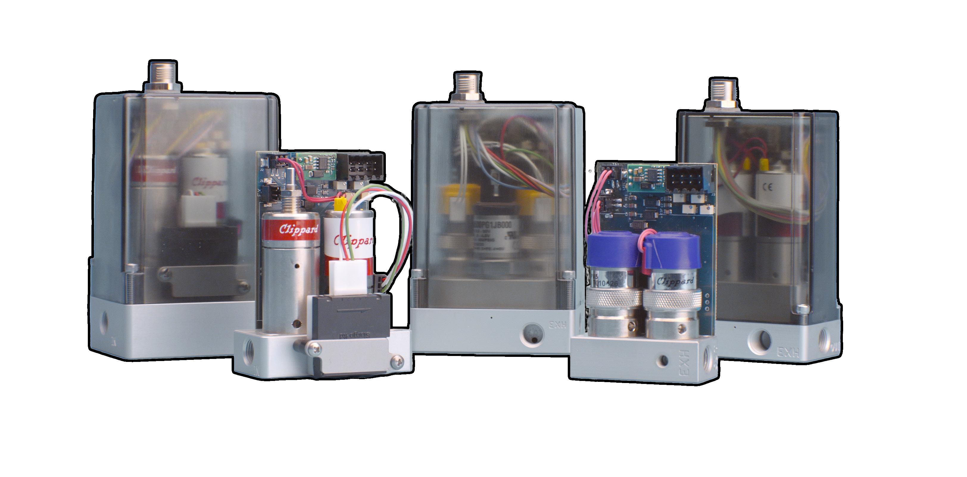
• Real-time adjustable PID control
• Integrated 0 to 10 VDC, 4-20 mA signal, or 3.3 VDC serial communication
• 0 to 10 VDC feedback pressure monitor
• Virtually silent
• No integral bleed required
• Multiple pressure ranges from vacuum to 150 psig
• 2.7 to 65 l/min flow control

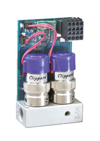

digital. Clippard’s Cordis products are revolutionary microcontrollers primed for escape velocity from a proportional control market that has grown stagnant.
With unparalleled performance and flexibility not possible with current analog proportional controllers, the Cordis makes everything from calibration, to sensor variety, to future development opportunities more accessible and less complicated.
Contact your distributor today to learn more about how the Cordis can provide precise, real-time control for your application, or visit clippard.com to request more information.