WILLIAM TALAMANTES
Portfolio
William Talamantes
Email: wbilltalamantes@gmail.com
EDUCATION PROFILE

I am a 26 year old California Polytechnic San Luis Obispo Grad, with two years of experience working as an Architectural Designer for Kava Massih Architects. I was responsible for generating and managing 3D Revit Architectural Models, in addition to producing Architectural Drawing sets for Sb330 and Zoning Applications.
Linked in: https://www.linkedin.com/ in/william-talamantes-978178146
CALIFORNIA POLYTECHNIC BACHELOR’S OF ARCHITECTURE
DIABLO VALLEY COLLEGE
WORK EXPERIENCE
ASSOCIATES IN SCIENCE IN ARCHITECTURAL DESIGN
KAVA MASSIH ARCHITECTS ARCHITECTURAL DESIGNER
Sep 21, 2022 - Aug 23, 2024
Use of Revit to generate Architectural Drawing sets for submital to the city of Berkeley Planning Department.
PYATOK ARCHITECTURE FIRM INTERN DESIGNER
Feb 16, 2021 - April 23, 2021
SKILLS
DIGITAL
Use of Revit for development of project sheets, attending meetings, and generating Land Use maps using Adobe Illustrator.
ANALOGUE


RHINO
REVIT
ENSCAPE
LUMION PHOTO SHOP
V RAY ILLUSTRATOR
IN DESIGN


WATER COLOR
HAND DRAFTING
GRAPHITE
MODEL MAKING


RENDER
GRAPHITE
WATER COLOR

KMA 1408 Milvia
3-18
KMA 2550 Shattuck 31-42 43-48 3. 4. In Service (Student Project)

KMA 1408 Milvia
Proposed 8 story 209,309 square foot mixed use mutli family housing project in Berkeley, Ca.
AND STUDY SPACE (FLOORS ABOVE 1ST FLOOR).
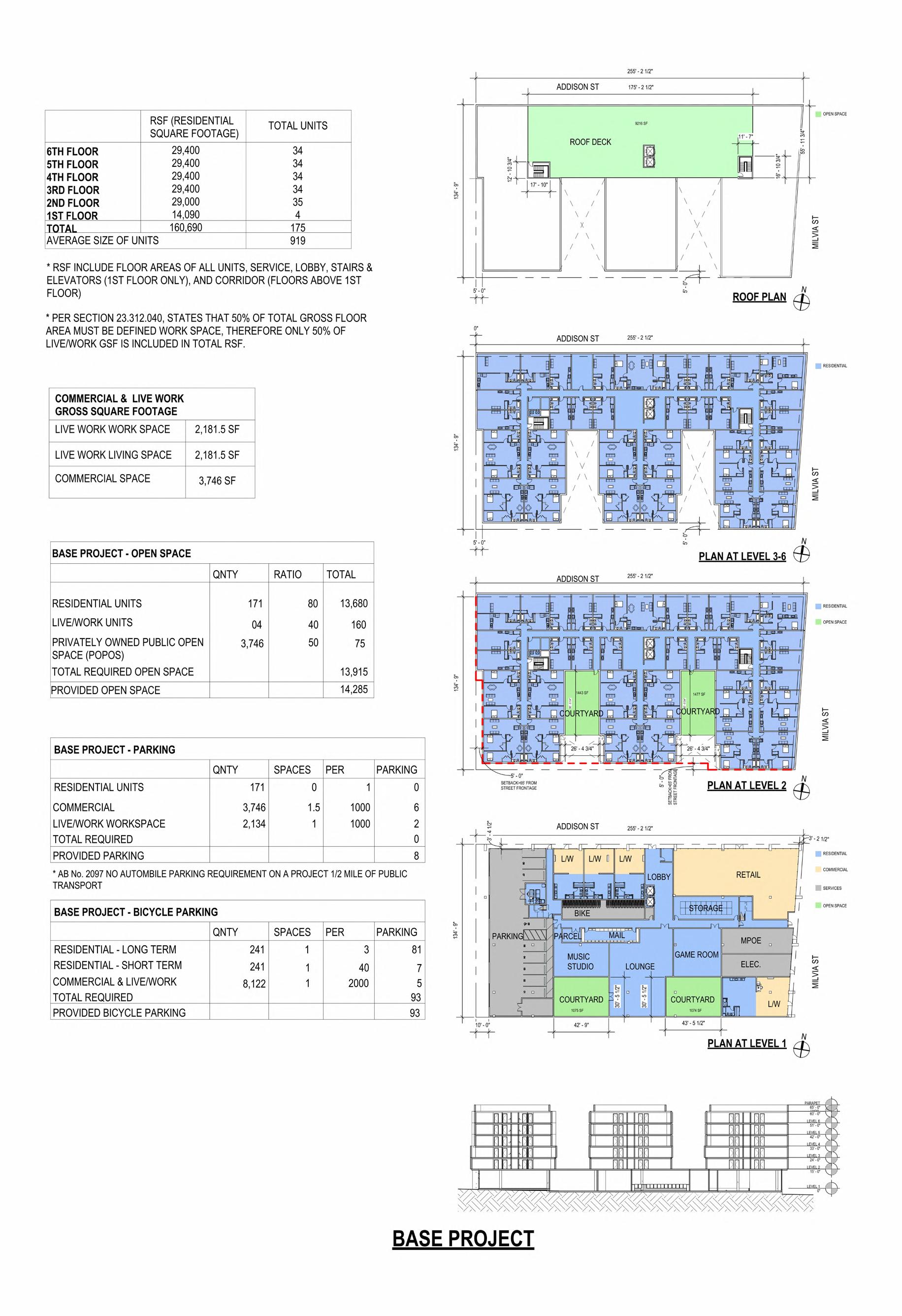

• I began each project by looking through the Berkeley Municipal code, and then provide a table breaking down the code to the Principal Architect.
• I would then generate a Base project in Revit, based off of the principal Architects design.
• The next step was to create a seperate Proposed project, increasing the height of the building and make slight design adjustments. This model would then be used as the final file to produce the drawing sets.
• The density bonus sheet allowed us to compare the base and proposed project, and show to the planning department how our project is a solution for the housing problem.
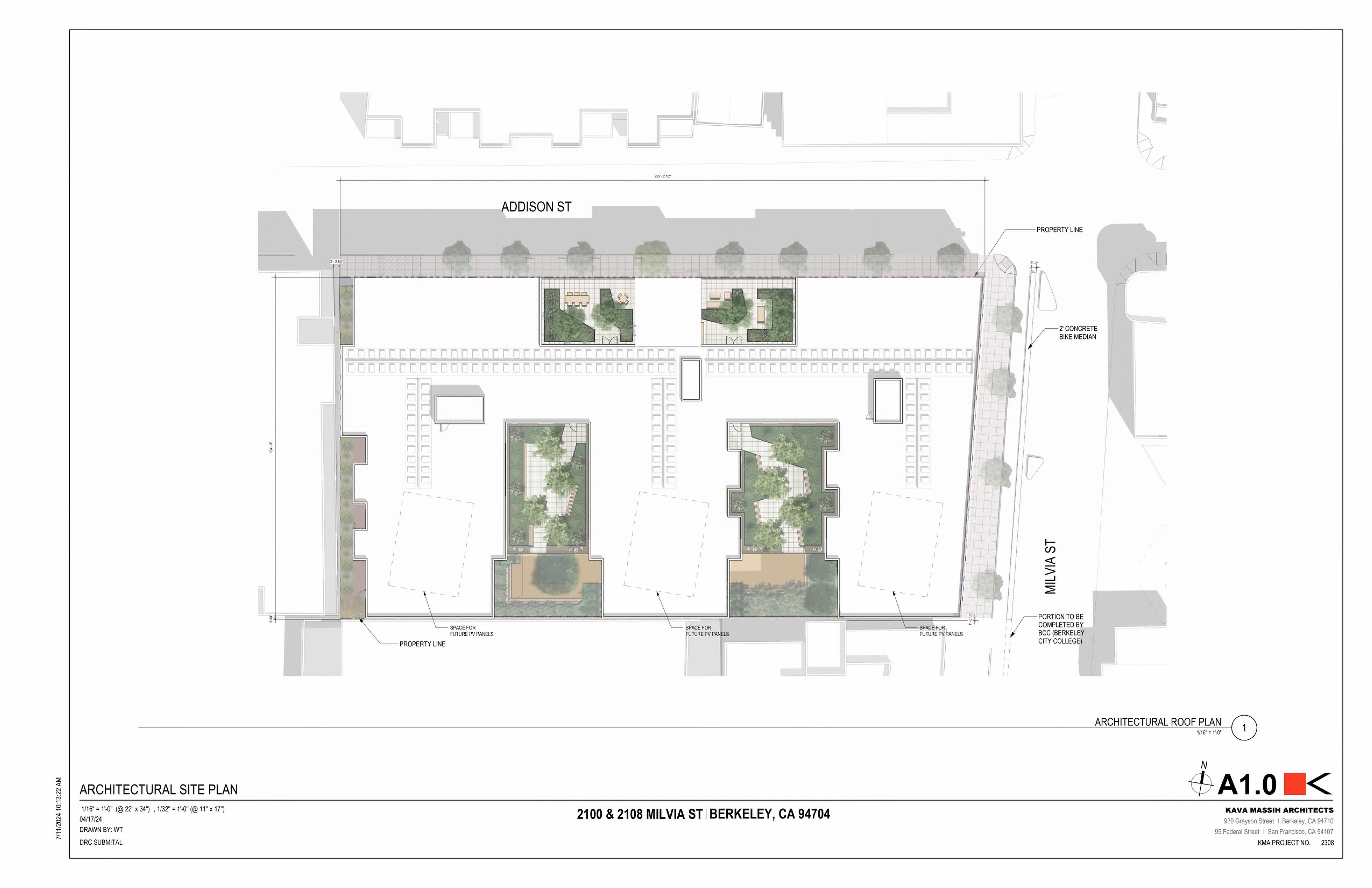

• With further completion of the Revit model, I would create an aerial plan to show the projects relationship to the surrounding buildings.
• The Landscape was developed by GLS Landscaping.
• To create this sheet I combined the Landscaping drawings and our aerial view in photoshop and then imported that jpeg file back into Revit for the Architectural Site Plan.
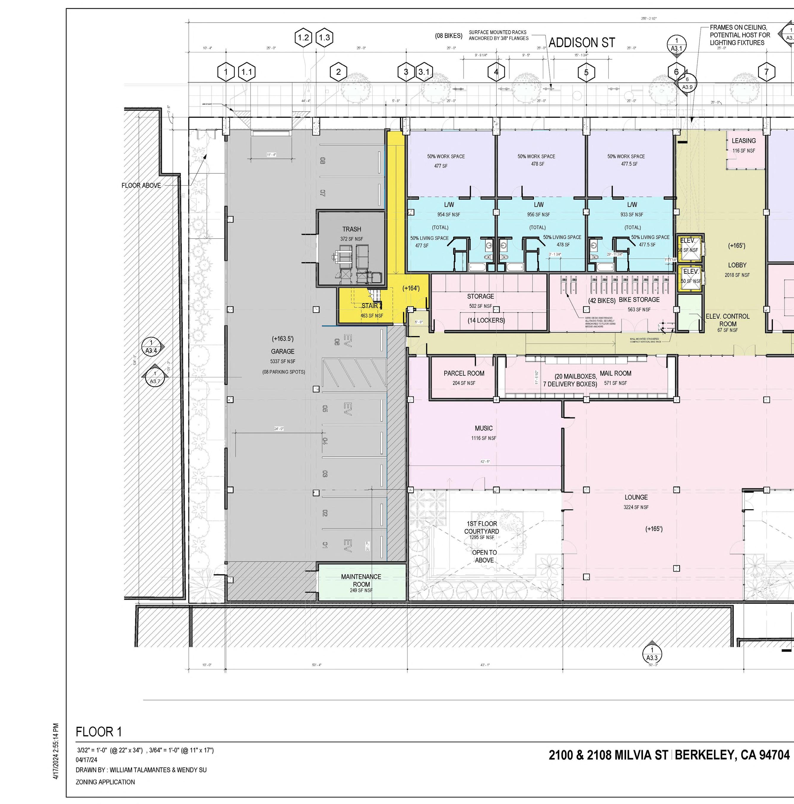
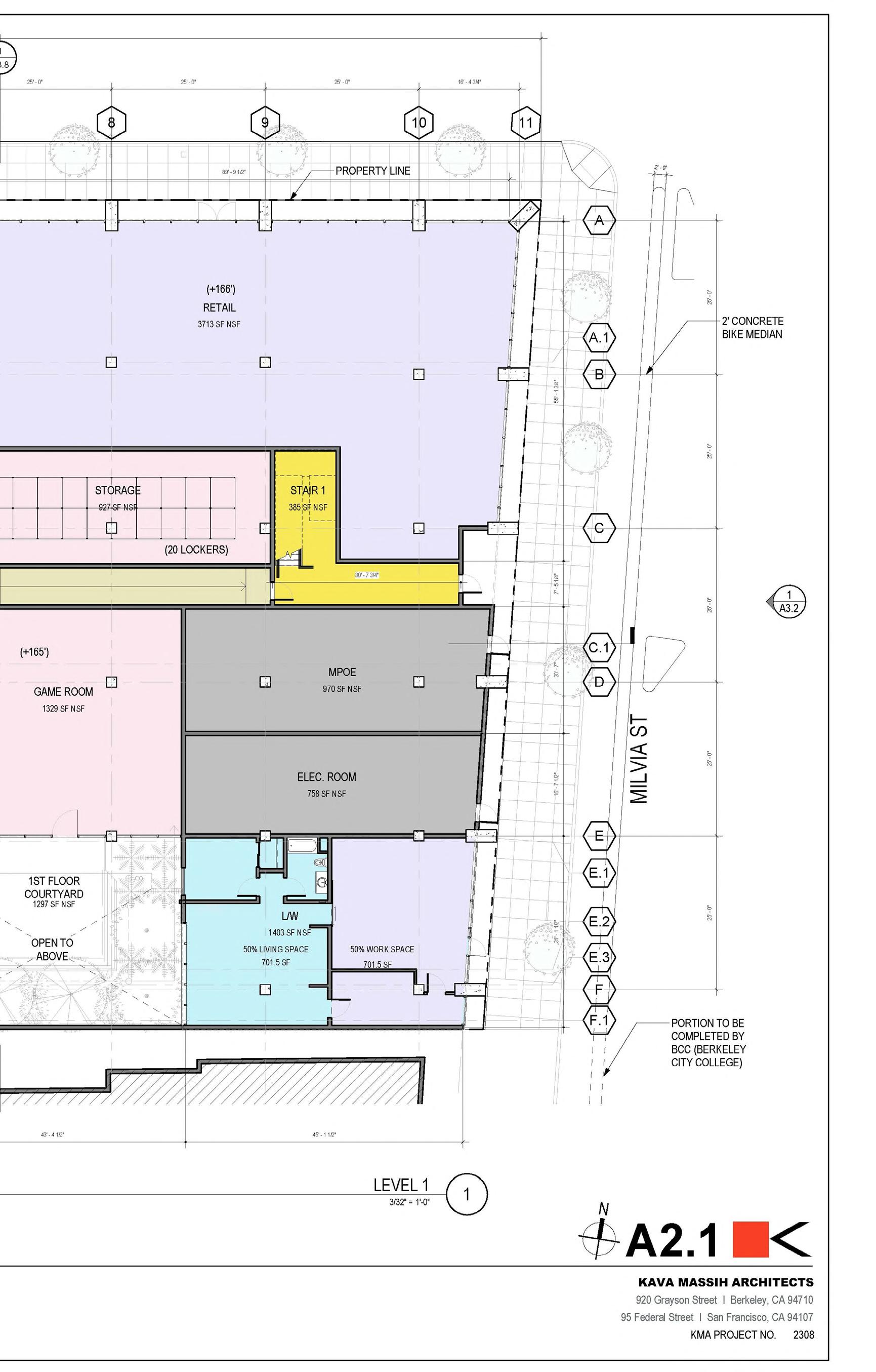
• After creating the floor plan in Revit based on the Principal Architects layout, I then imported the Auto CAD landscaping files produced by GLS to create a more comprehensive Ground floor.
• The color scheme used was a KMA standard Zoning application color scheme.
• The Principal Architects would look over the sheet at least once a week to make sure I was keeping with KMA standards, and meeting the zoning requirements.
• The zoning requirments included but were not limited to making sure that 10% of parking was EV designated, with an addition EV space being ADA accesible.
• There was also at least a single bike parking for every 3 units. But, this could be reduced in our waiver requests.
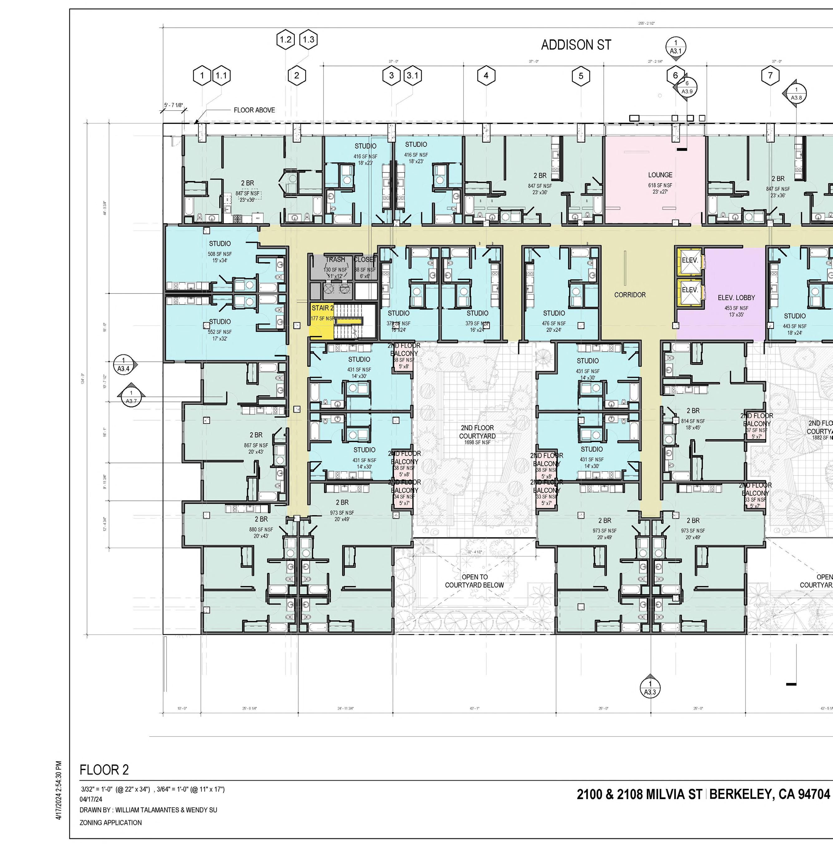
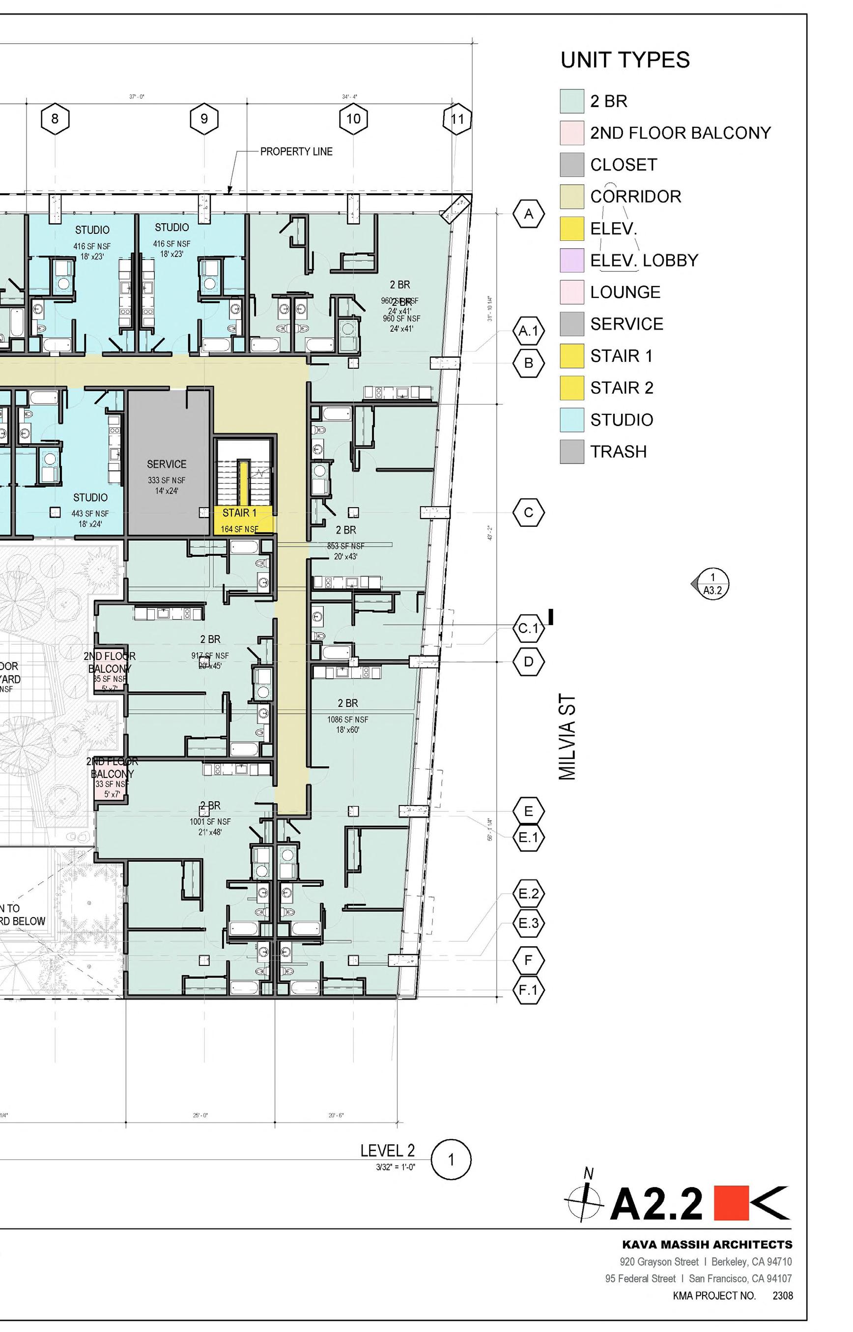
• The unit layout was decided by the principl Architect, and the client. I would then create their vision in Revit.
• Most of the unit make up was studio and 2 bedrooms because this seemed to be the most profitable model for student housing.
• For this and other plans I would place the dimensions, but it would be looked over by the Principal Architects. Then I would tidy them up.
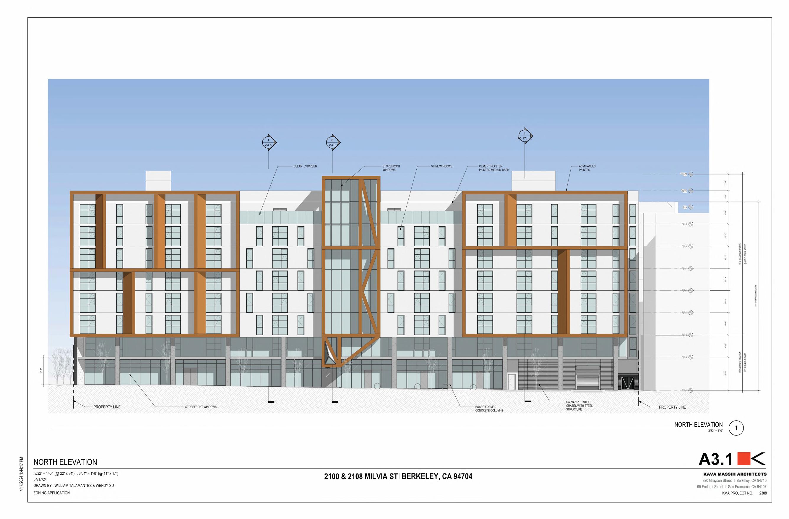
• The design choices for the elevations were entirely crafted by the Principal Architect. But, it was my responsibilty to them generate in Revit.
• With each design choice/update, I would submit the Principal Architect views of the project sometimes 2D or 3D, and then he would tell me where to make the adjustments.
• With an especially long facade we wanted to create a rhythm that would get rid of the monotony that comes with a 255’ long wall.
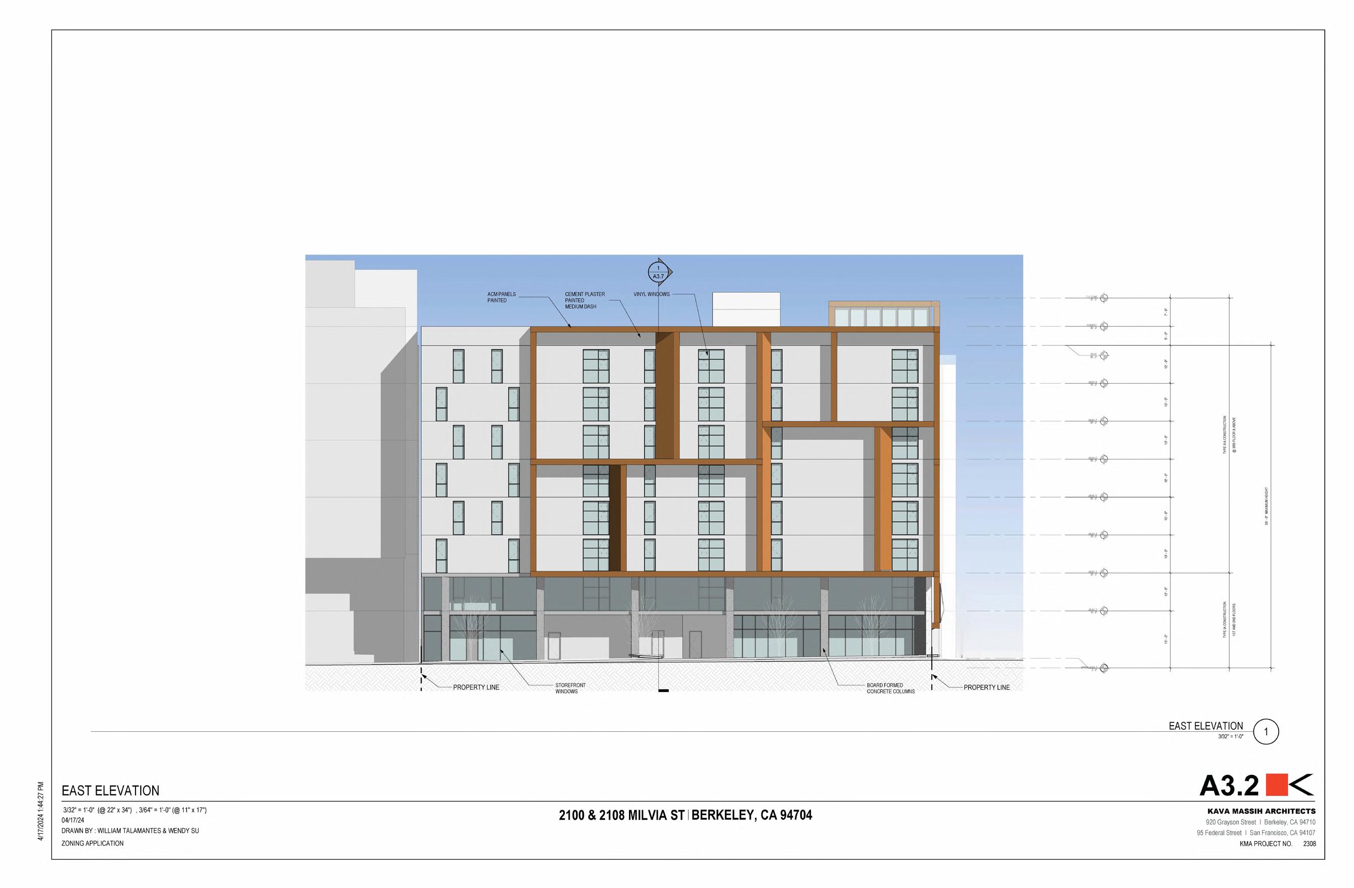
• In these elevations I would also include the surrounding proposed projects, to better represent the relationship of the project with the surrounding buildings in the near future.
• The elevation also showed that our building was not exceeding the height requirement of 85’ from the lowest point of entry/exit. This was especially important on sites with slopes, because that would impact the final height of the project.
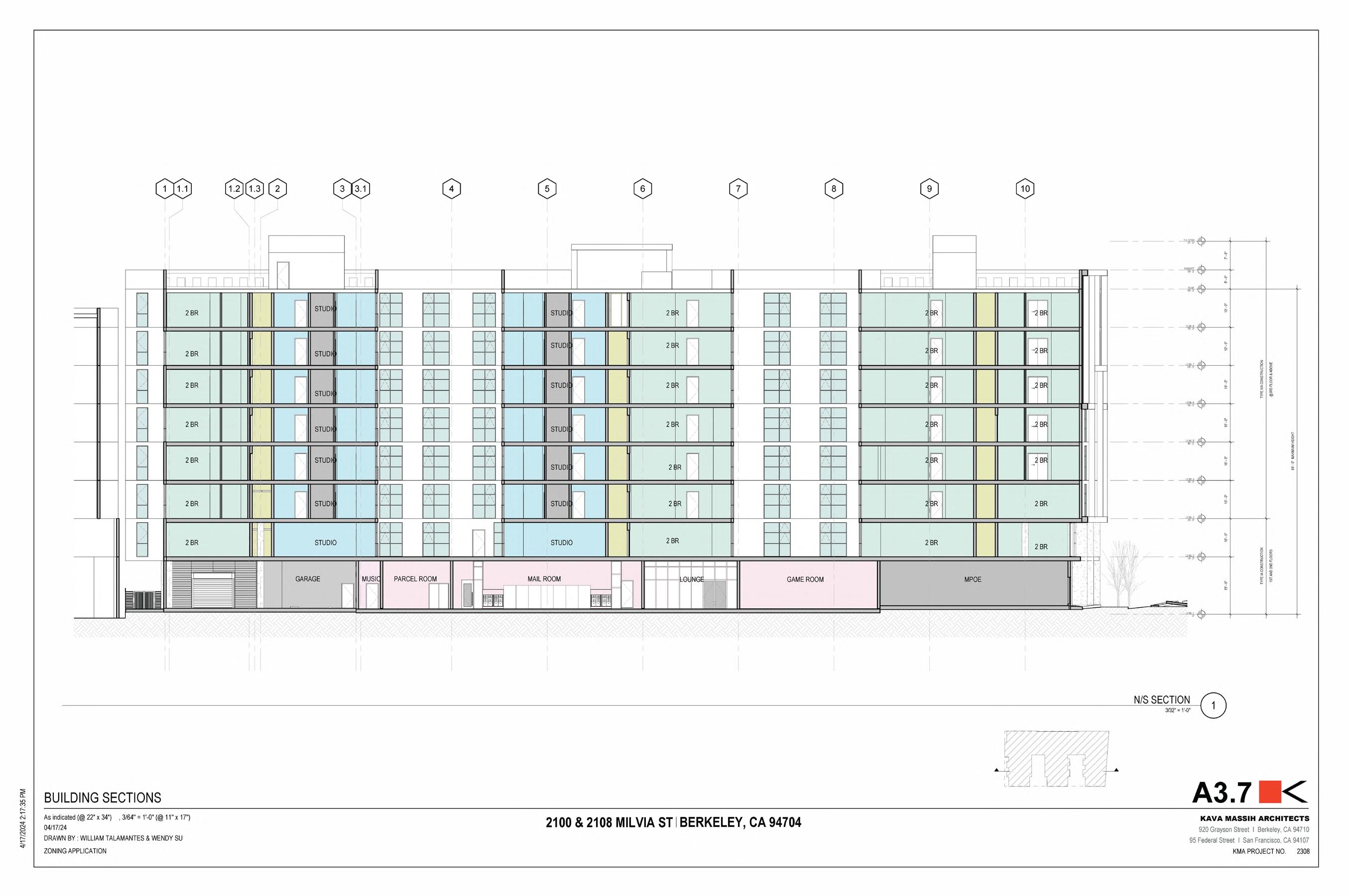
• When I would generate the sections I would always make sure the color scheme would match the color scheme represented in the floor plan.
• These sections were especially important to show the relationship between the second floor courtyard and the units around it.
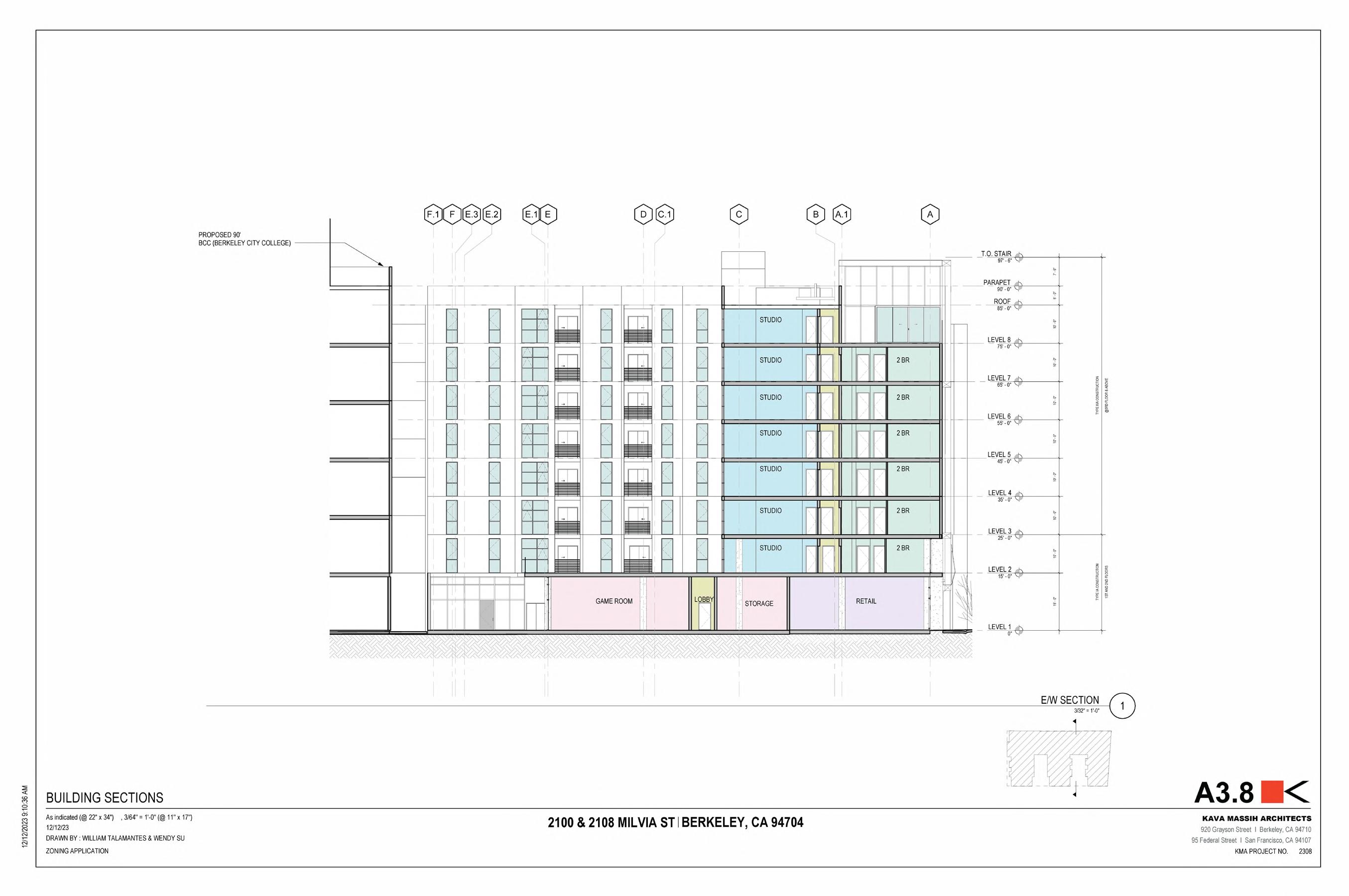
• The principal architect made sure that for this section I would cut through the open spaces at three different levels. With there being an open space on the ground floor, second floor, and eigth floor.
• In addition, this section shows the proposed 95’ building sitting directly south of our project.
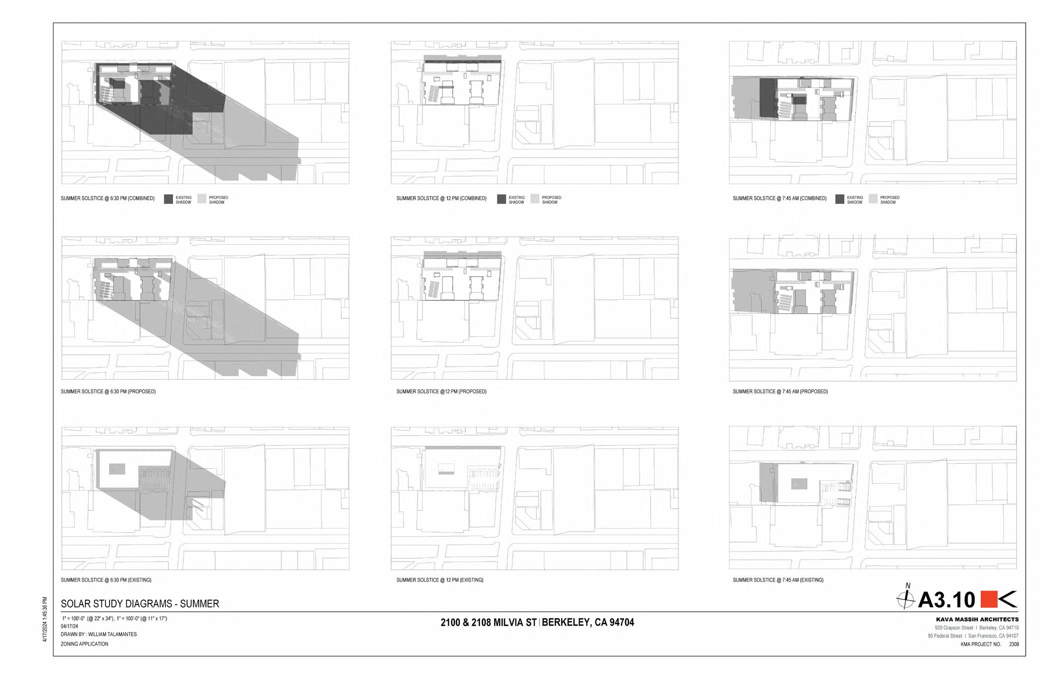
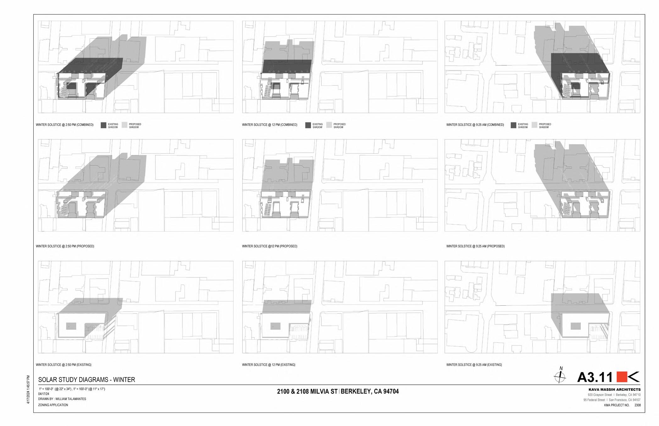
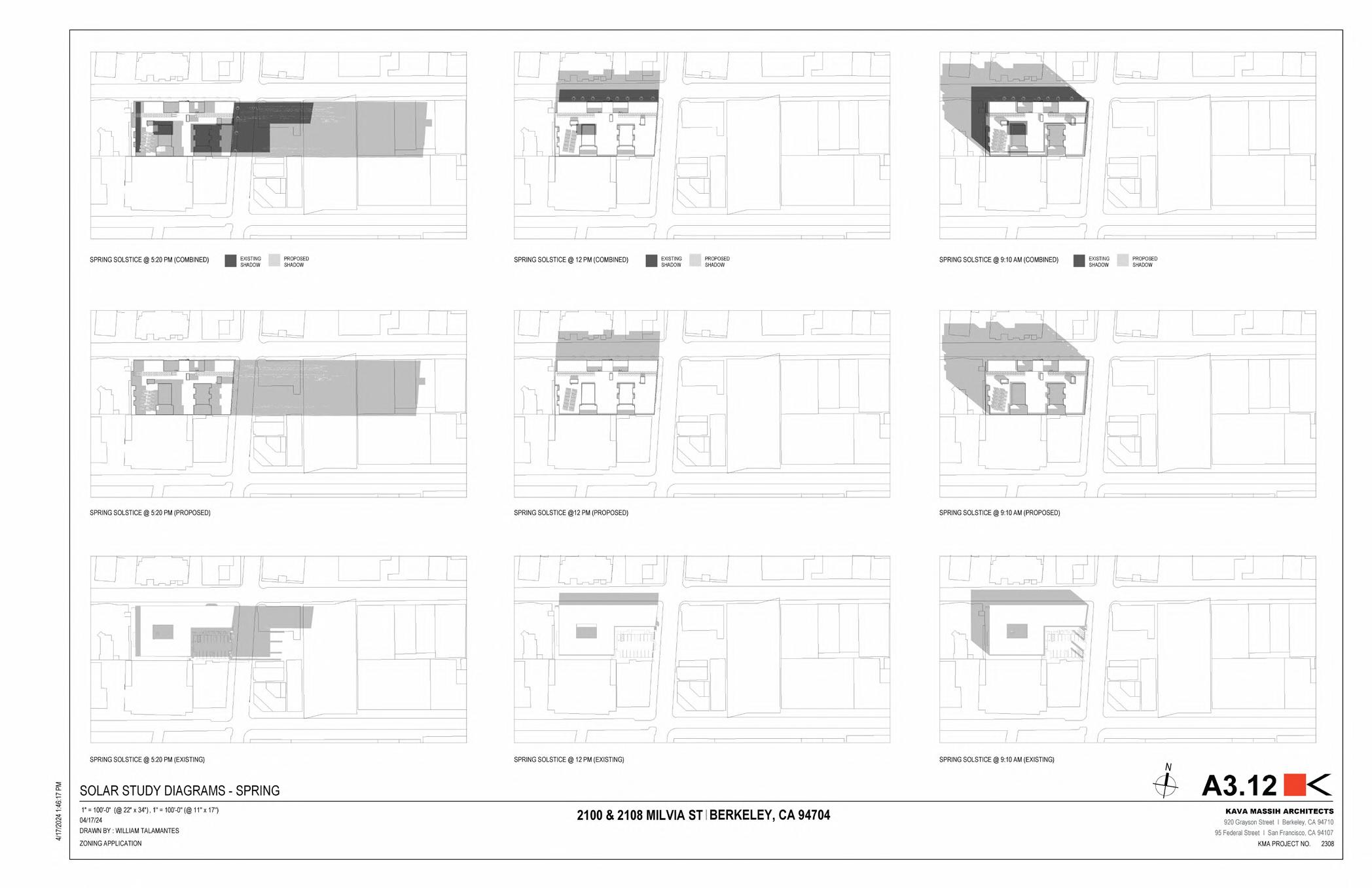
• I created these sun study diagrams entirely in Revit, using the cast shadow option and filled regions.
• The city would ask for the shadows casted by the base project, the shadows casted by the propsed project and then finally to overlay the two images.
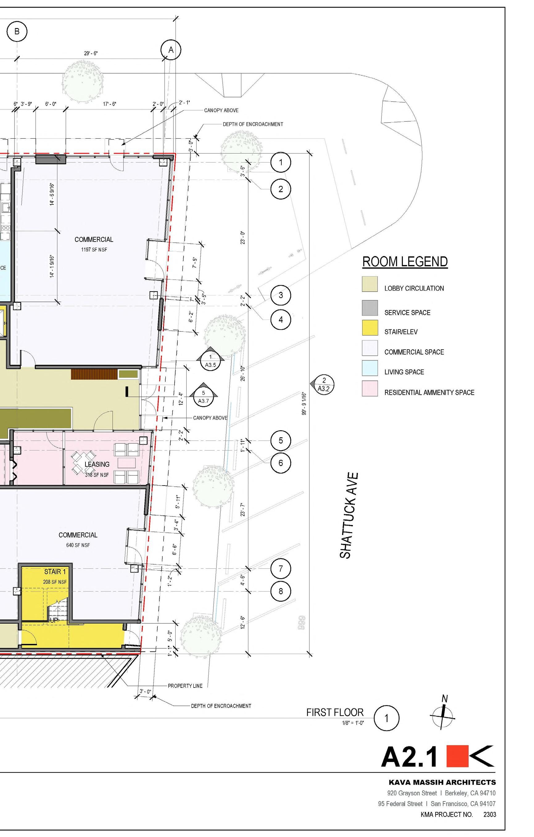
KMA 2550 Shattuck
Proposed 7 story 75,000 square foot mixed use multifamily housing project in Berkeley, ca.
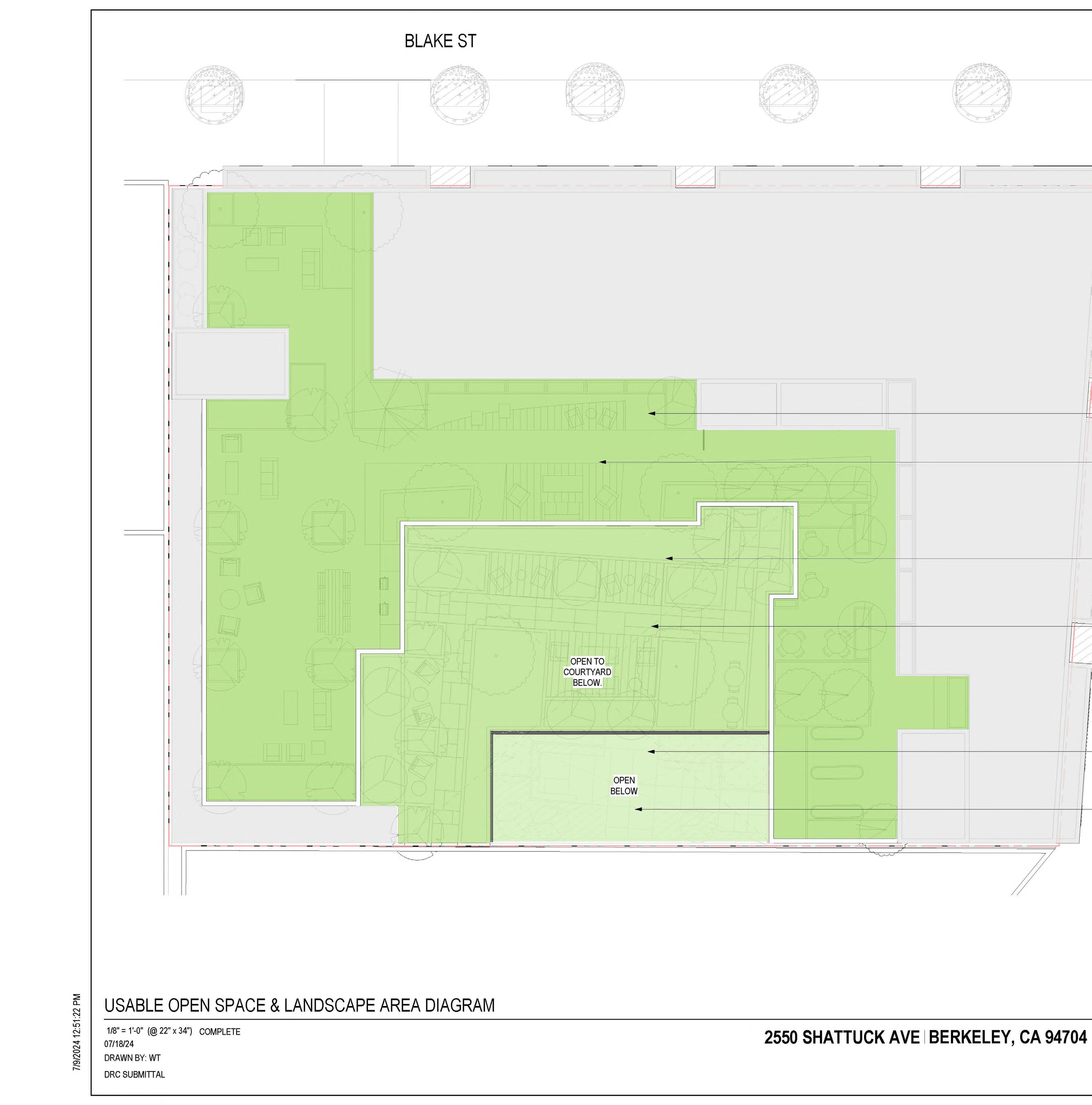
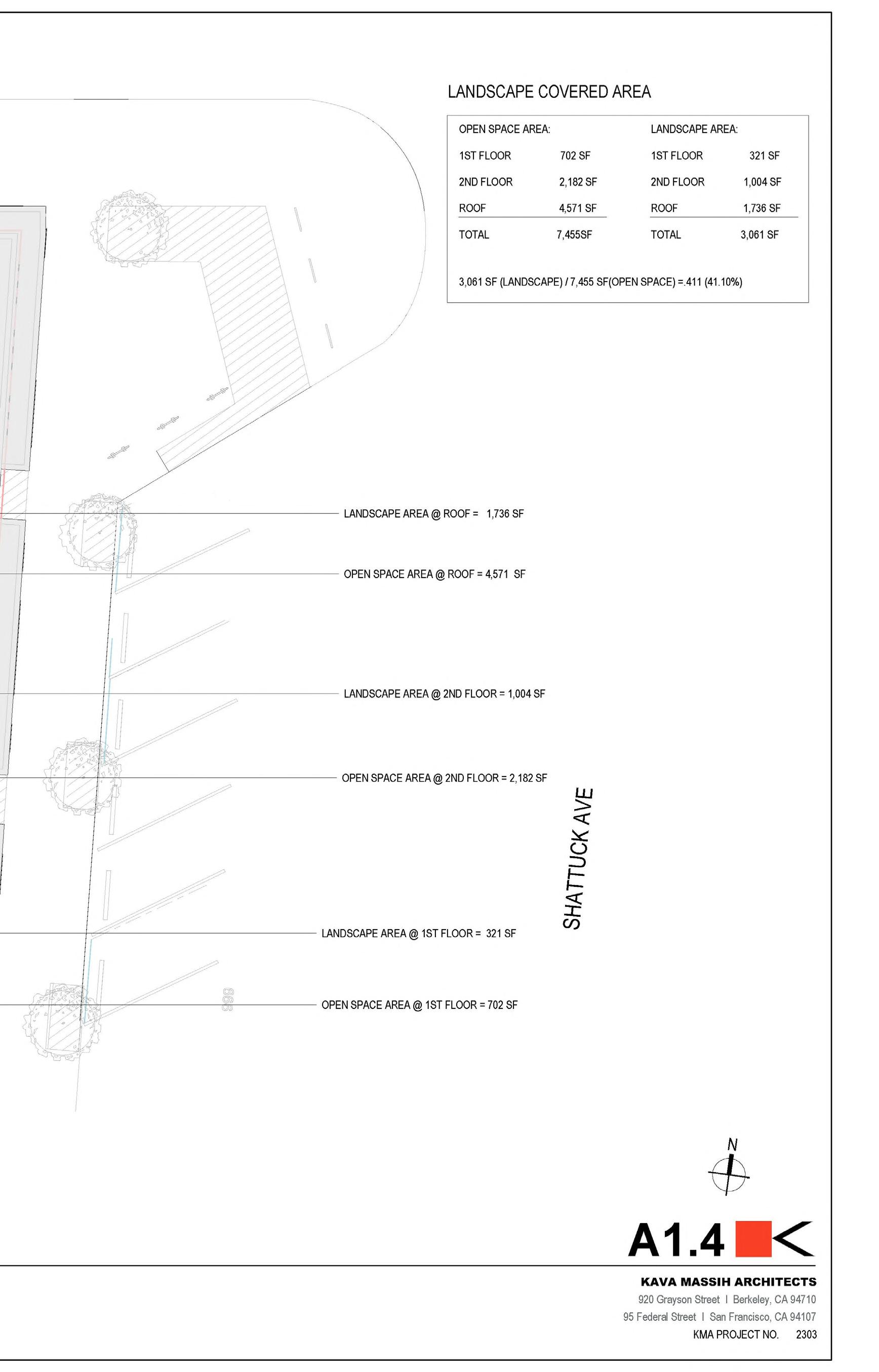
• Once the landscaping of the project was heavily figured out, I would then begin creating a Landscape Area Diagram.
• This sheet would express how much of the open space was landscaped. We were required to hit a 40% minimum.
• Those figures however would be calculated by the Landscaping firm we worked with, and then I would include them in this sheet.
• In addiiton, it showcased that three level open space theme we were implementing in our projects.
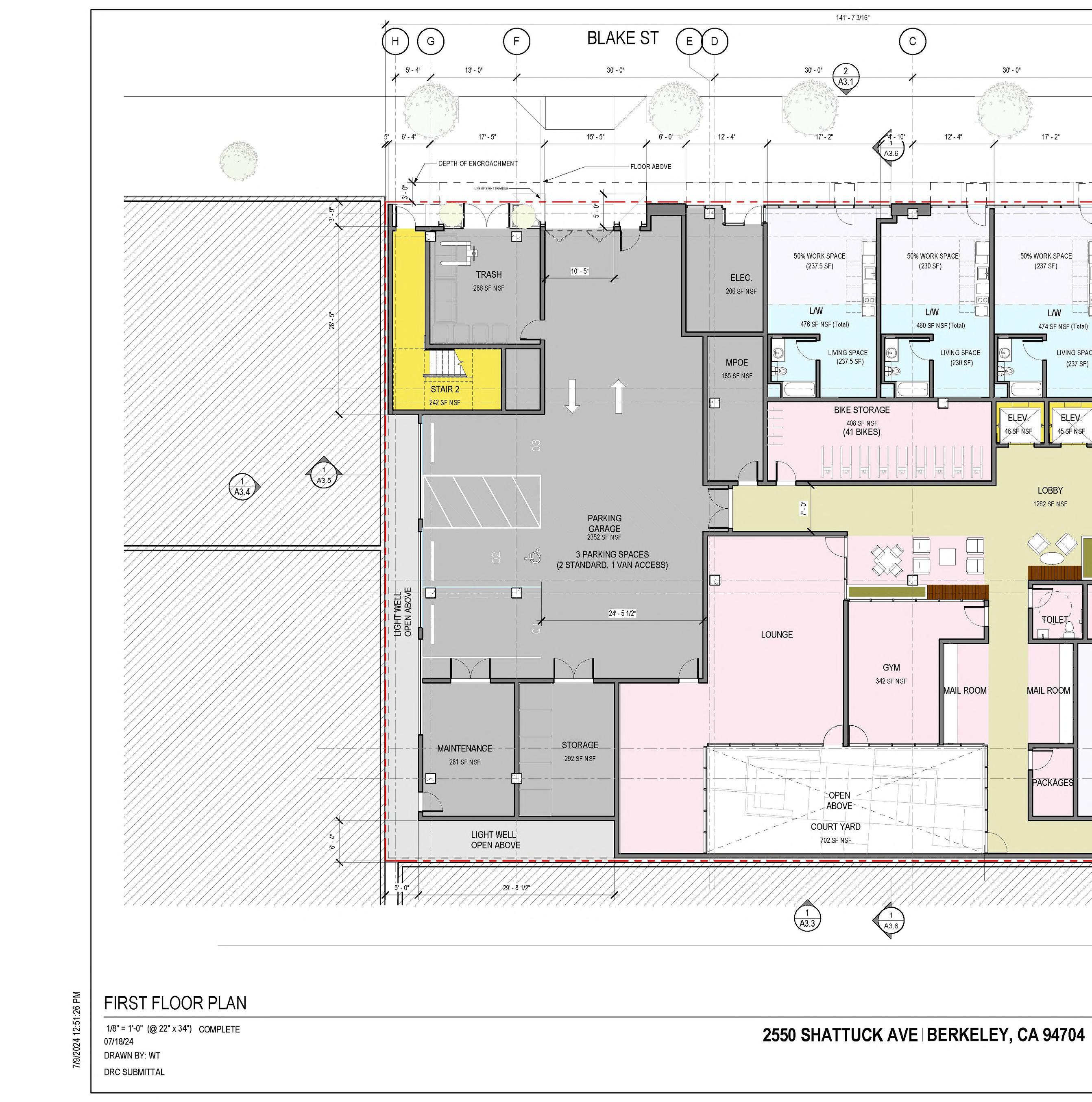
• I would constantly improve the floor plans further and further based on the Principal Architects feedback.
• The dimesnions were especially important to showcase to the city how much the bay windows were encroaching on the sidewalk.
• In addition, the dimesnions had to be included on the ground floor live work units to show that 50% of the units were work space, and the other 50% was for living accomodations.
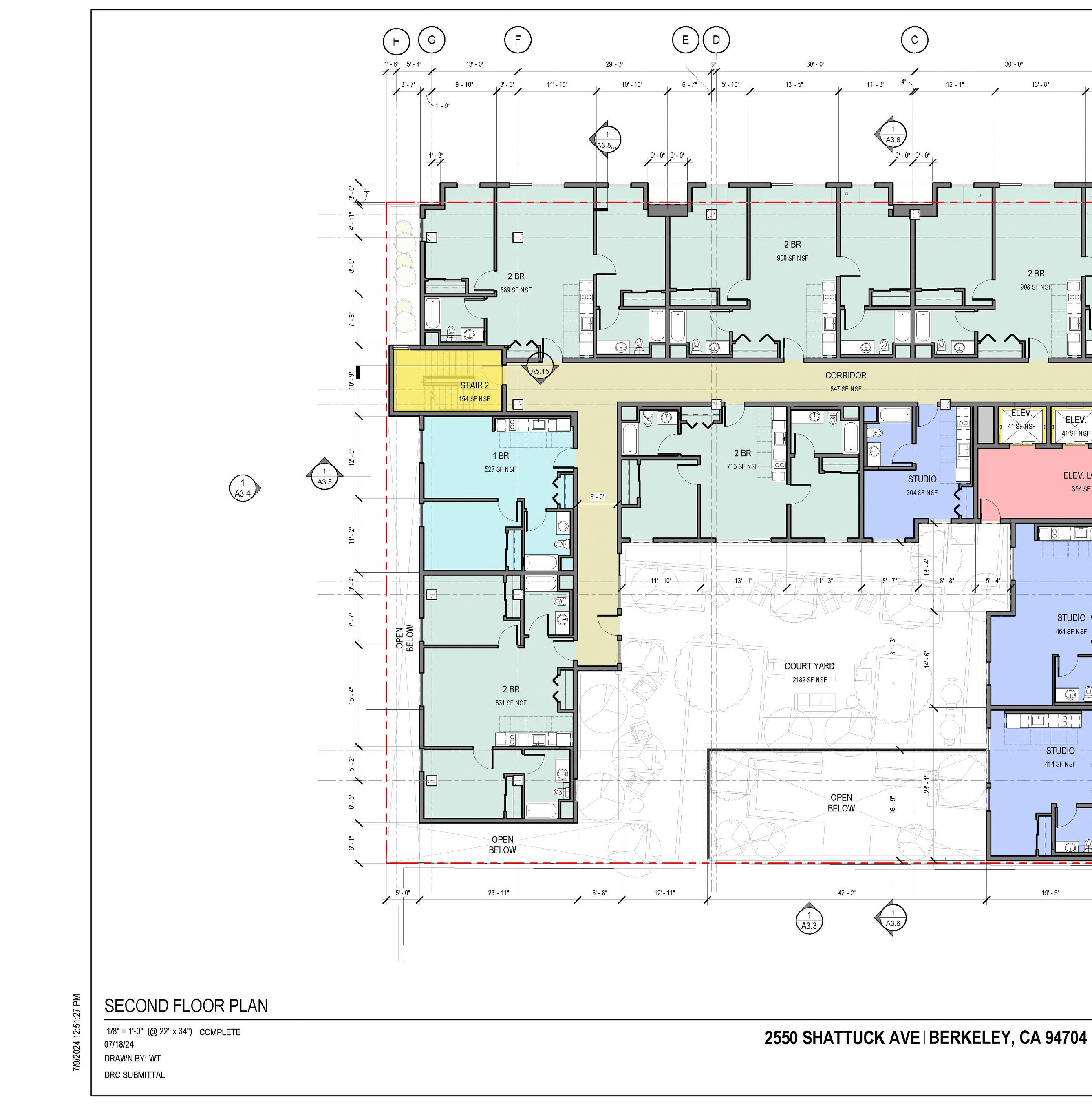
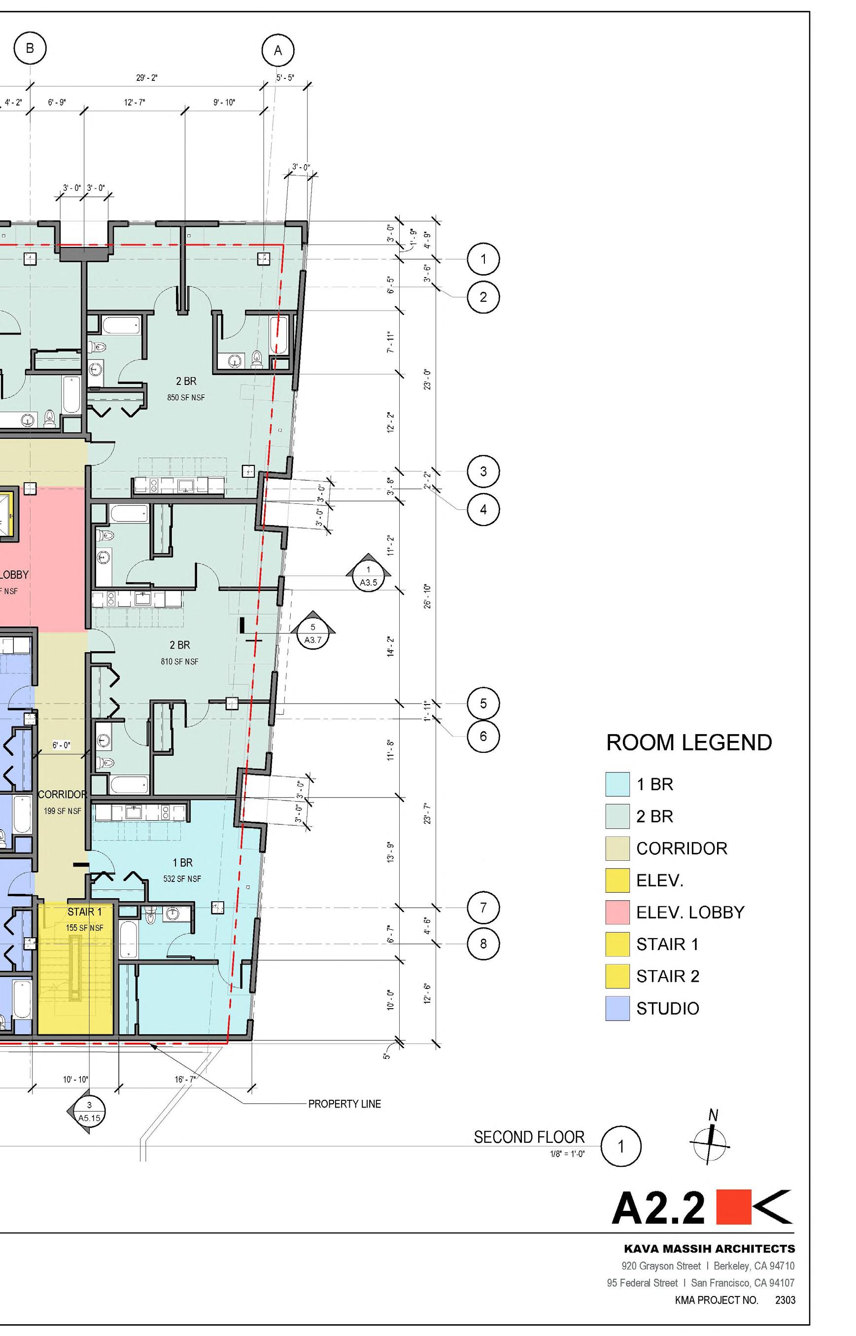
• The Principal Architect would decide all massing decisions and movements, as well as unit placement and then I would move those decisions into Revit.
• I would create unit layouts based on previous projects, and then the Principal Architects would mark them up for me to make adjustments.
• The dimension tags had to be especially accurate in the outdoor spaces and match the figures the Landscape Architects generated. City planning department would notice any of those discrepancies.
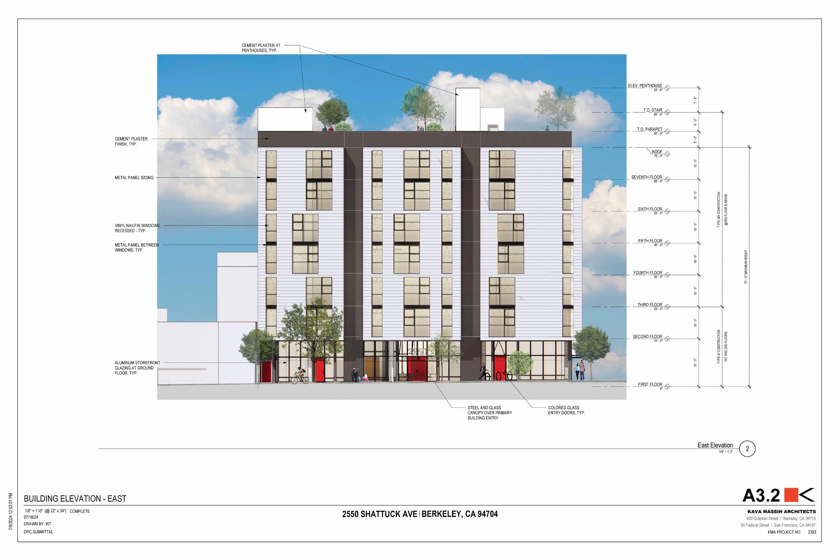
• I created these elevations in Revit, based on the Princiapl Architects design choices.
• Once the color and material was fairly thought through, I would then create Renderings to showcase the materiality until a final decision was made.
• I first used enscape to render these images, and then took them into photoshop to further develop them.
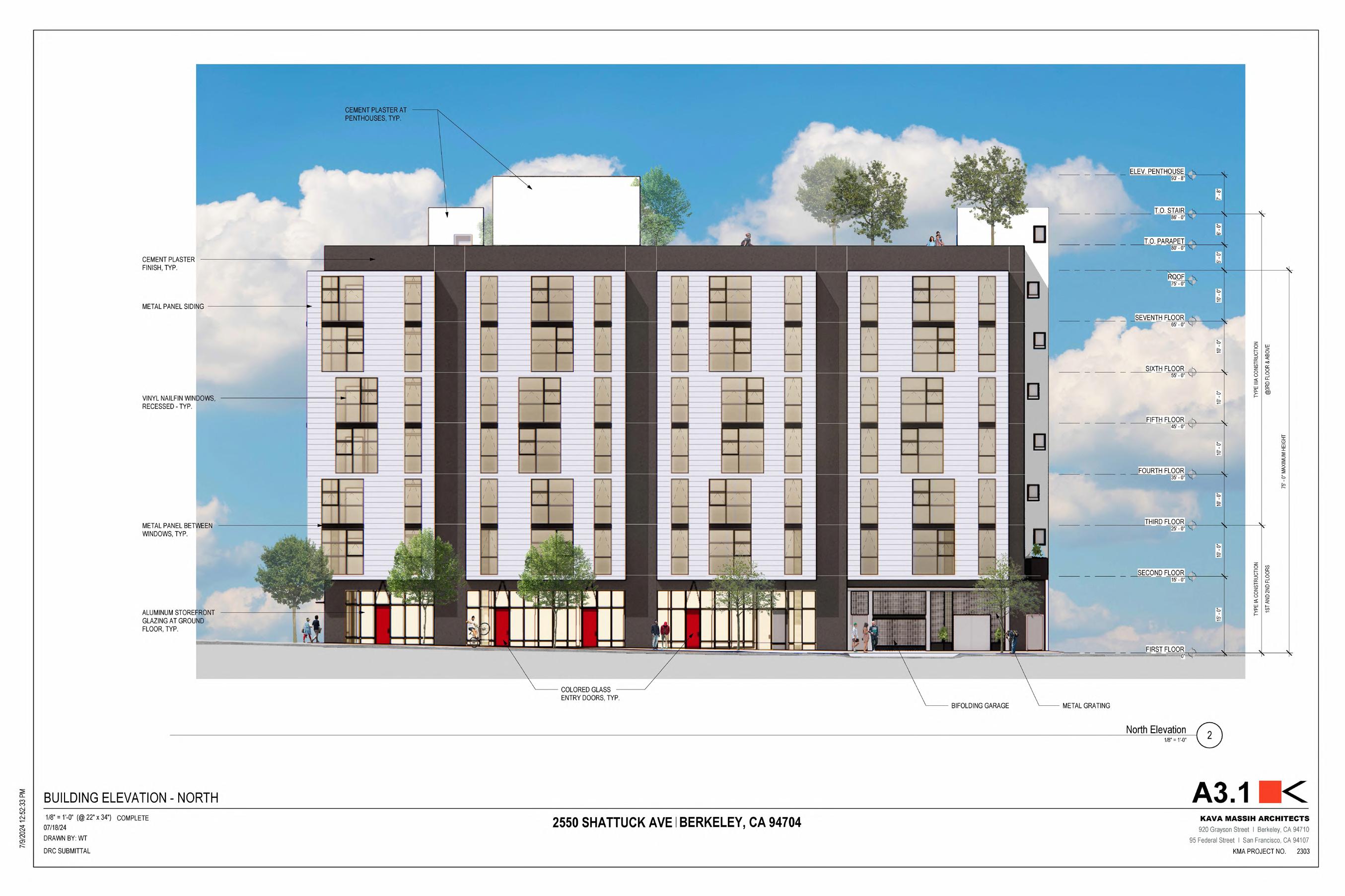
• The elevations did not need to be this developed for the SB330 application and Zoning application. But, rather for the Design Review board who are appointed members who approve commercial, manufacturing and some residential projects.
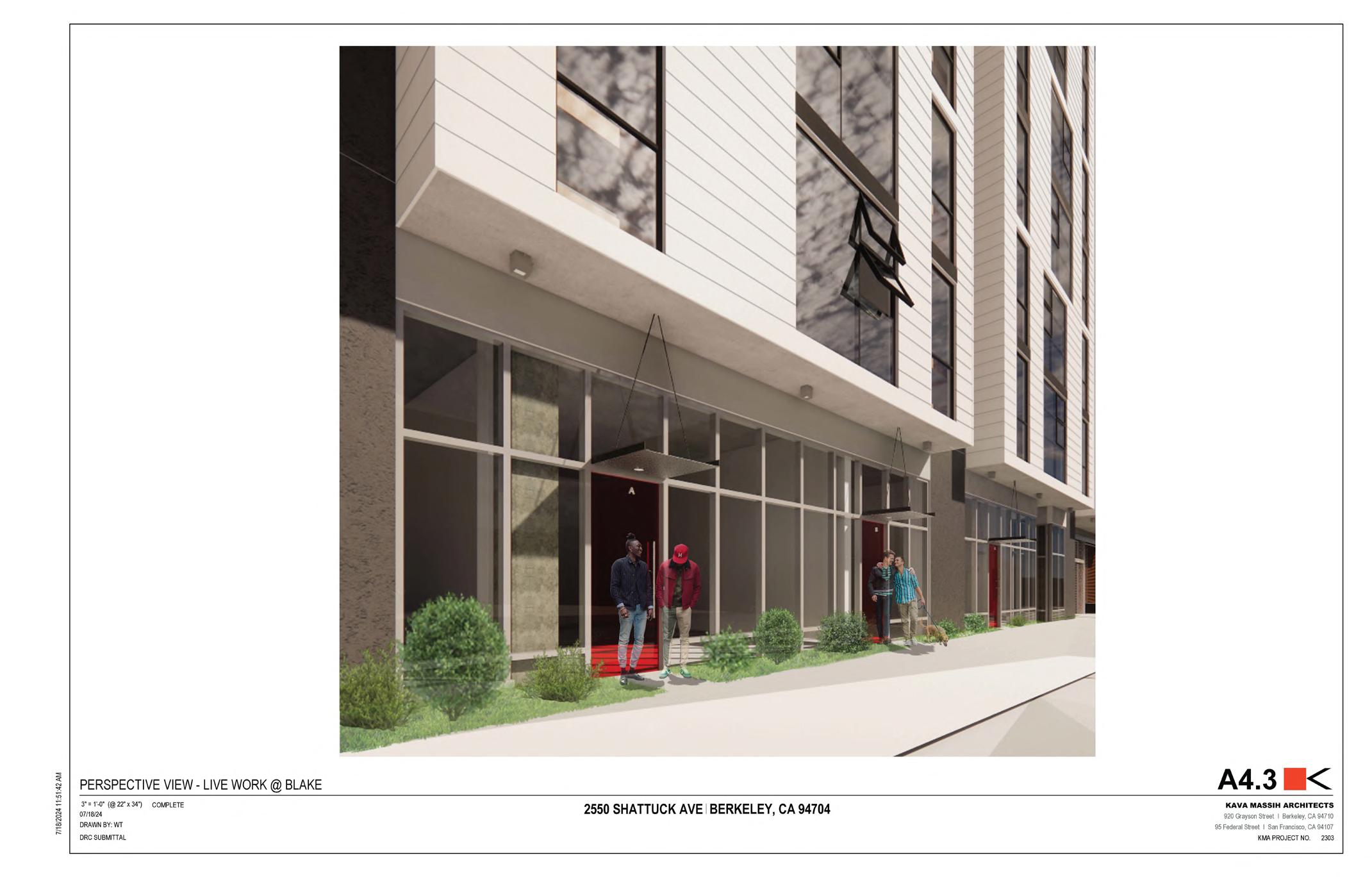
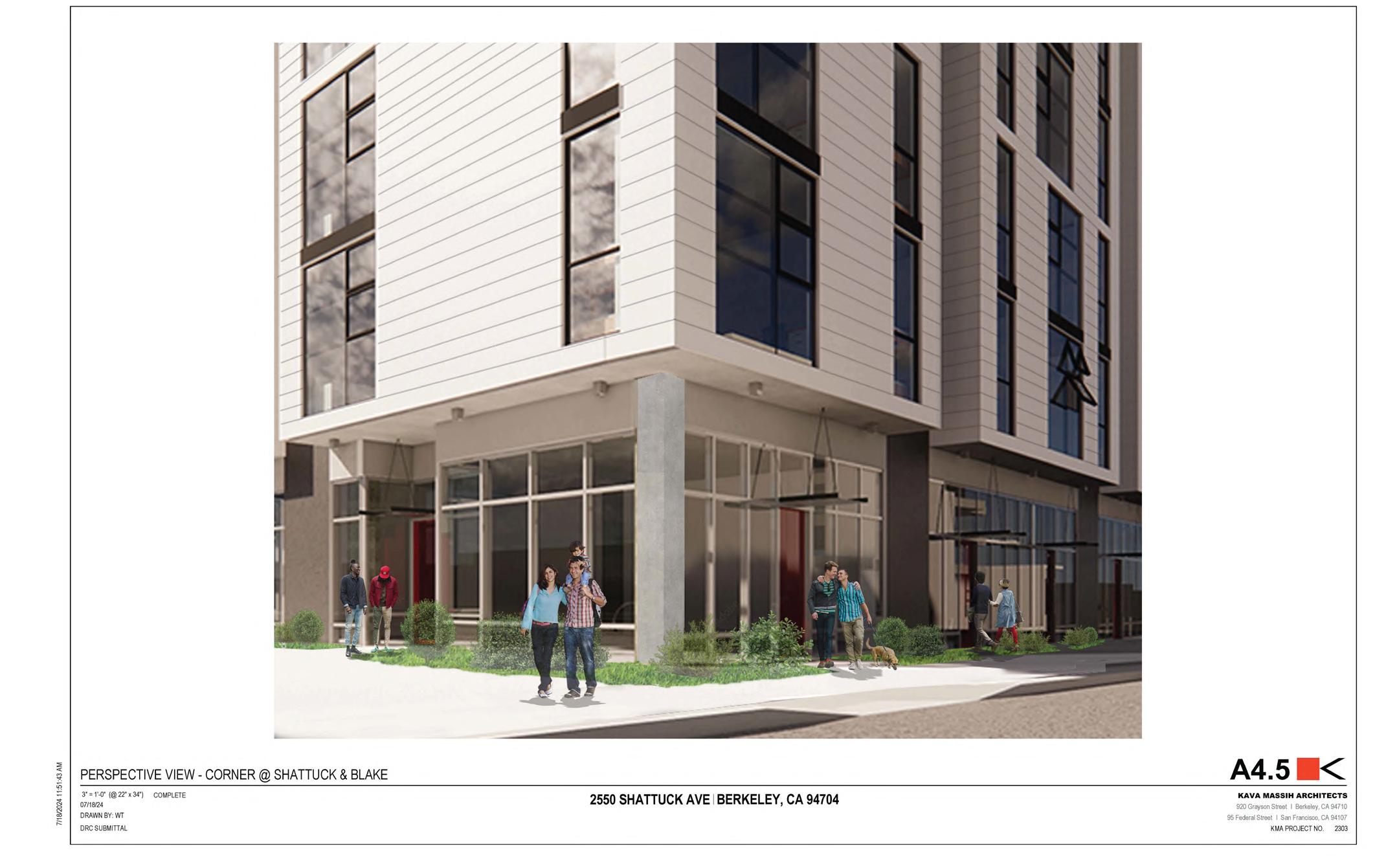

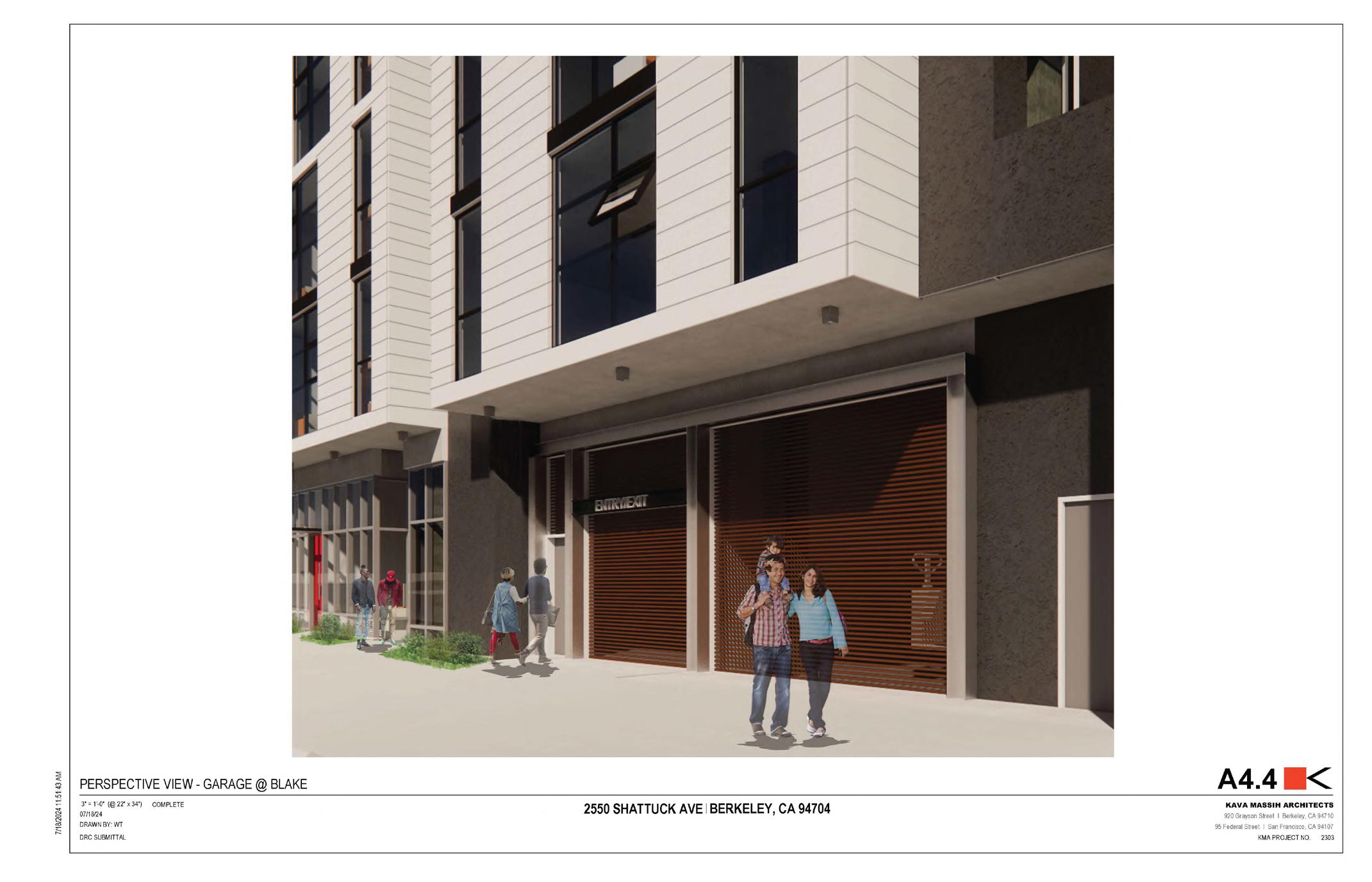
• I made these Renderings using Revit, Enscape and then Photoshop.
• Photoshop allows for a better inclusion of people, vegitation and texture.
• These views were asked for by the Design Review Board, and were not included in SB330 and Zoning application.
• These renderings were to showcase the relationship of the bays to the sidewalk below, and that they do little to no interfering to the sidewalk.
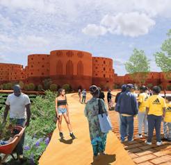
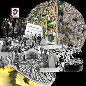
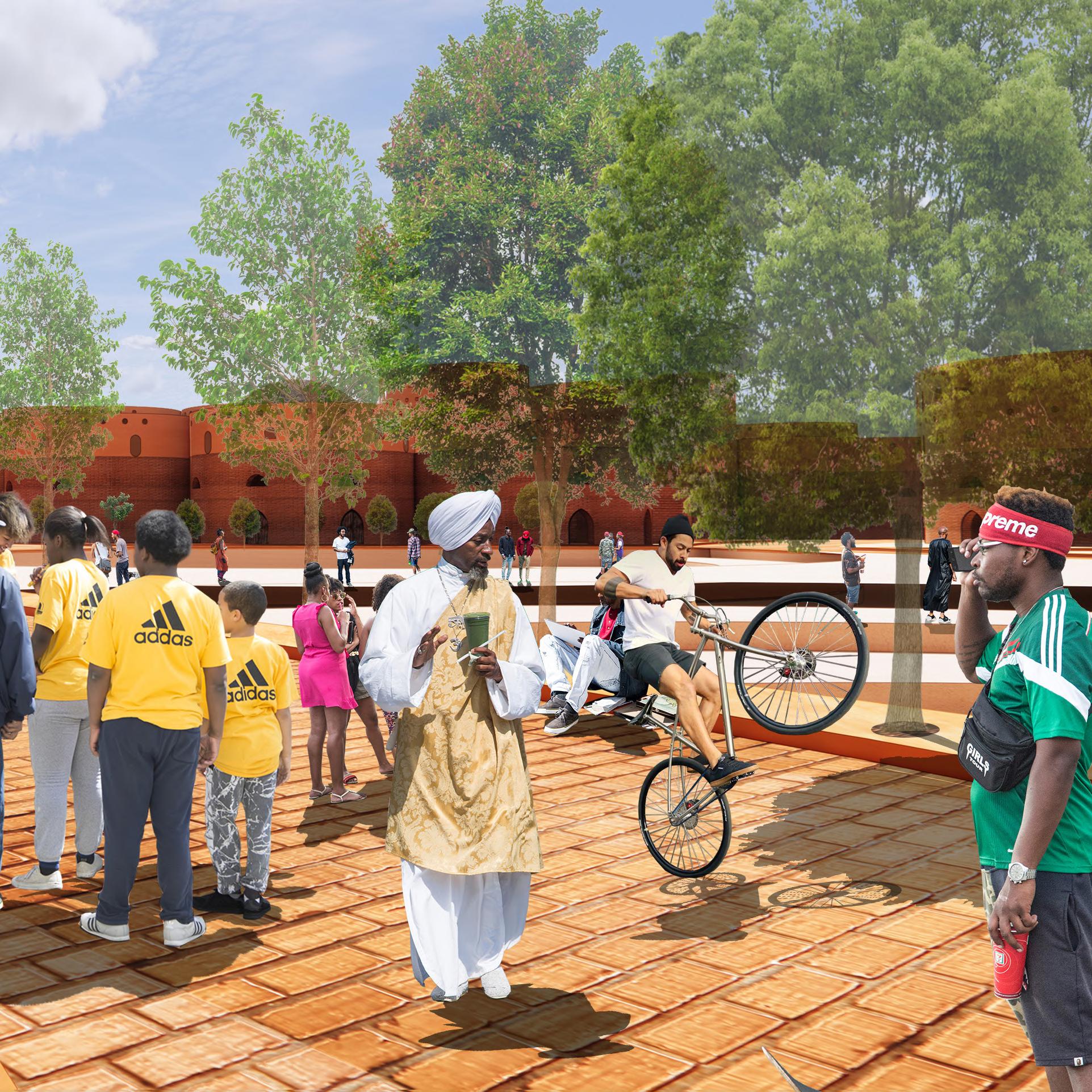
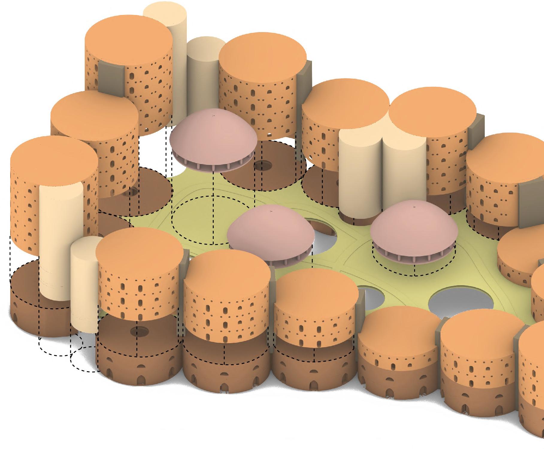
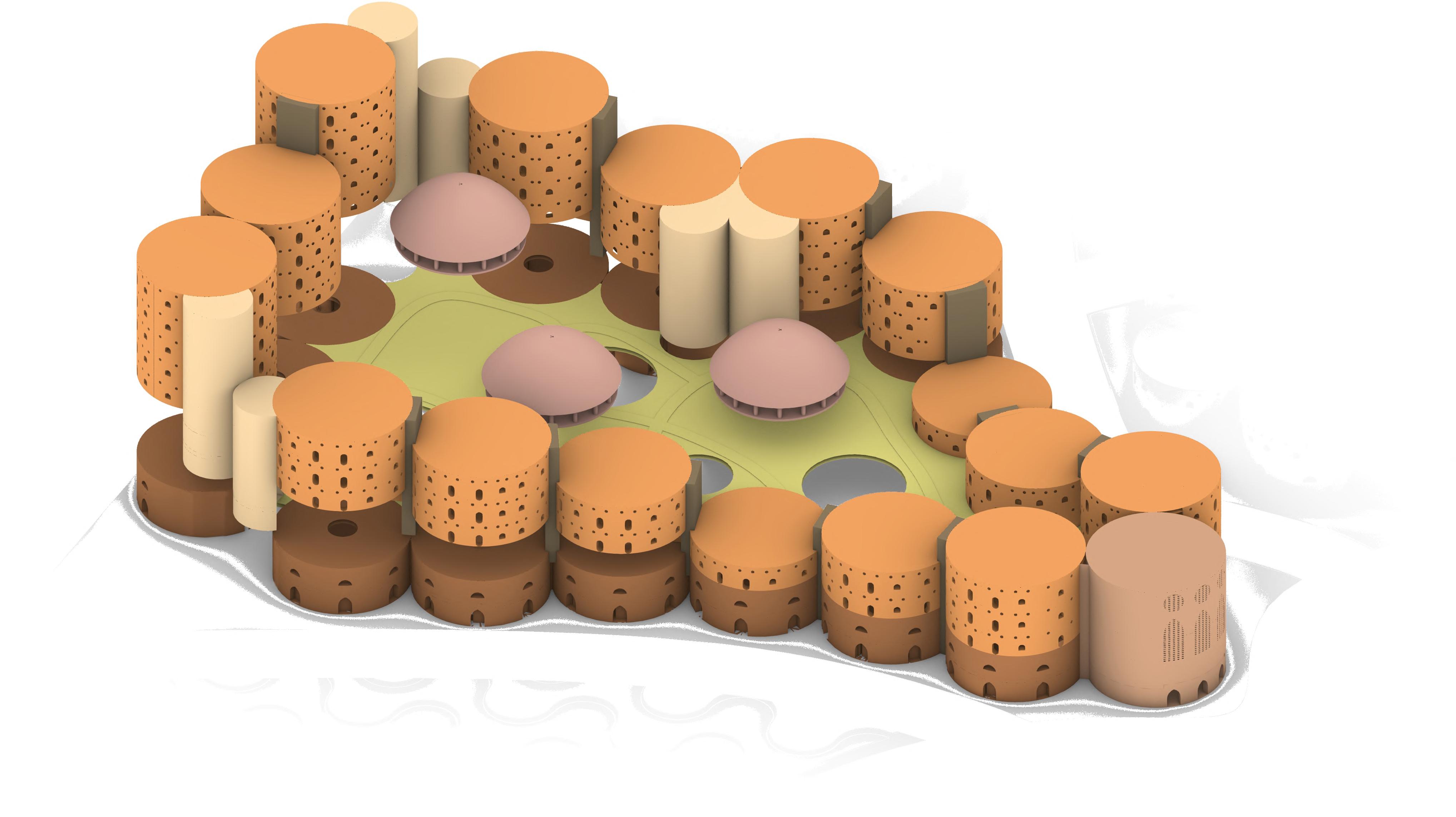
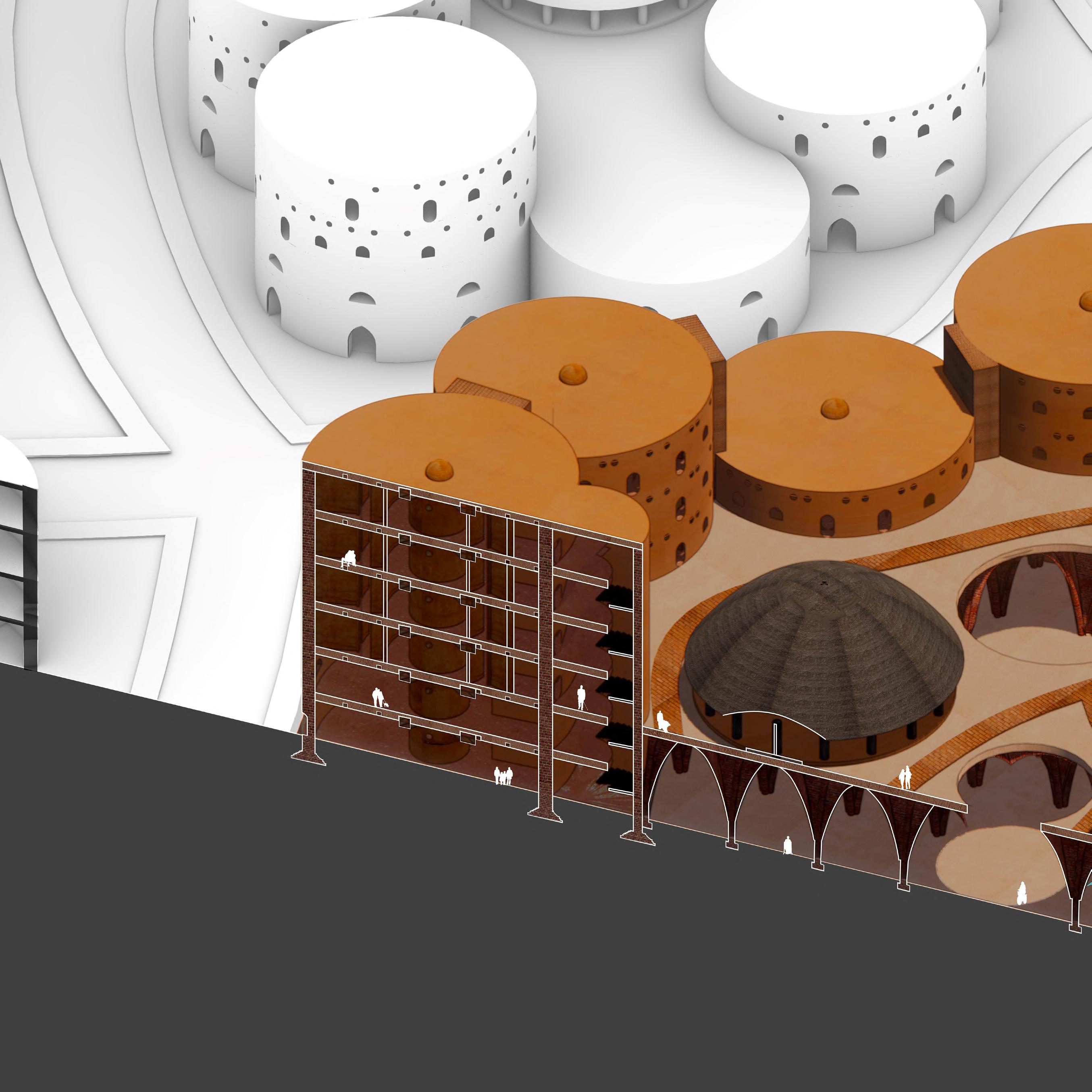
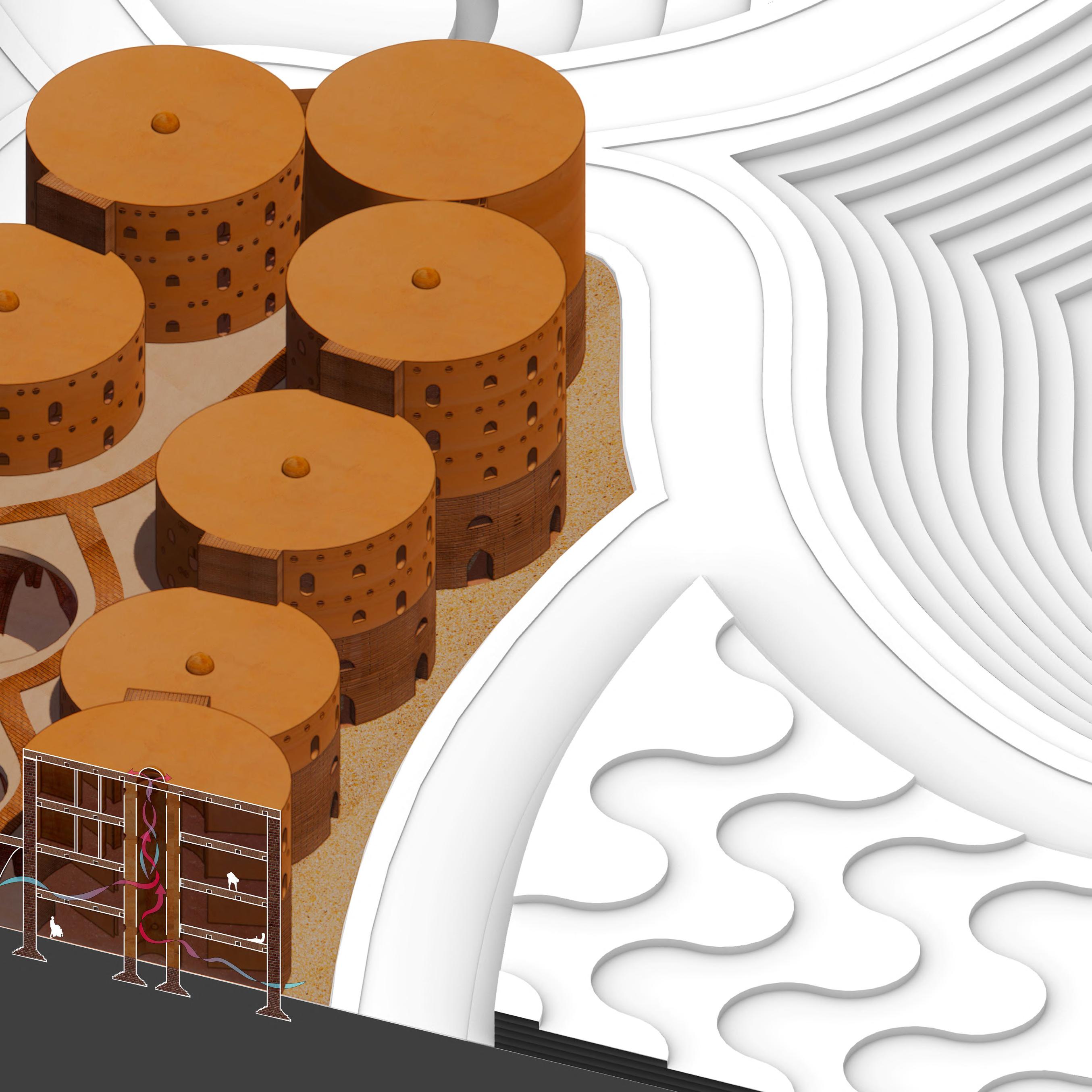
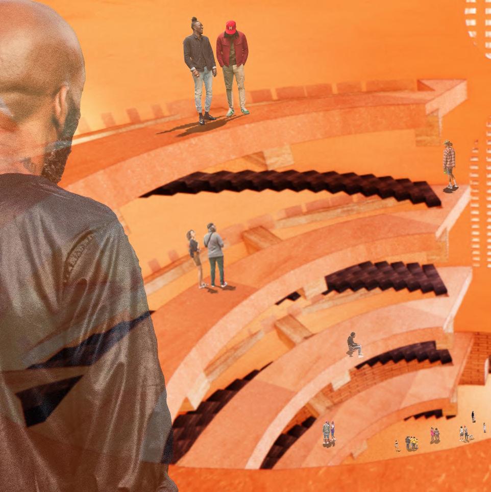
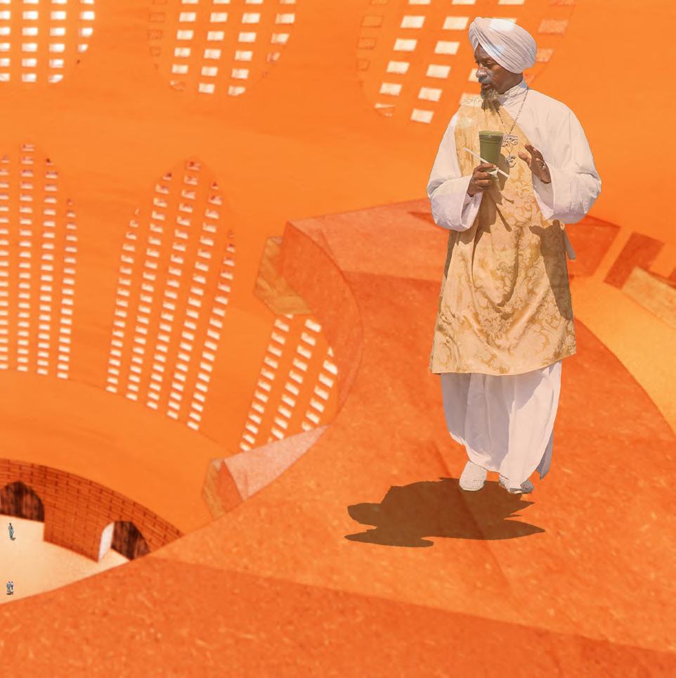
In Service (Student Project)

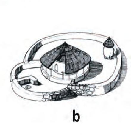
South Africa, a nation stratified. Where for the last 200 years architecture was used as a tool to control and dehumanize the Black, Indian and Colored populations. Therefore, in order to create a more equitable society one must begin by assisiting the most desinfranchised of a community. That is why I propose a mix use multifamily housing in a township (slum) of South Africa, built using local materials and labor. Thus creating a secure space where families and communities can grow, and further solutions can be generated to solve the ills plaguing society today.
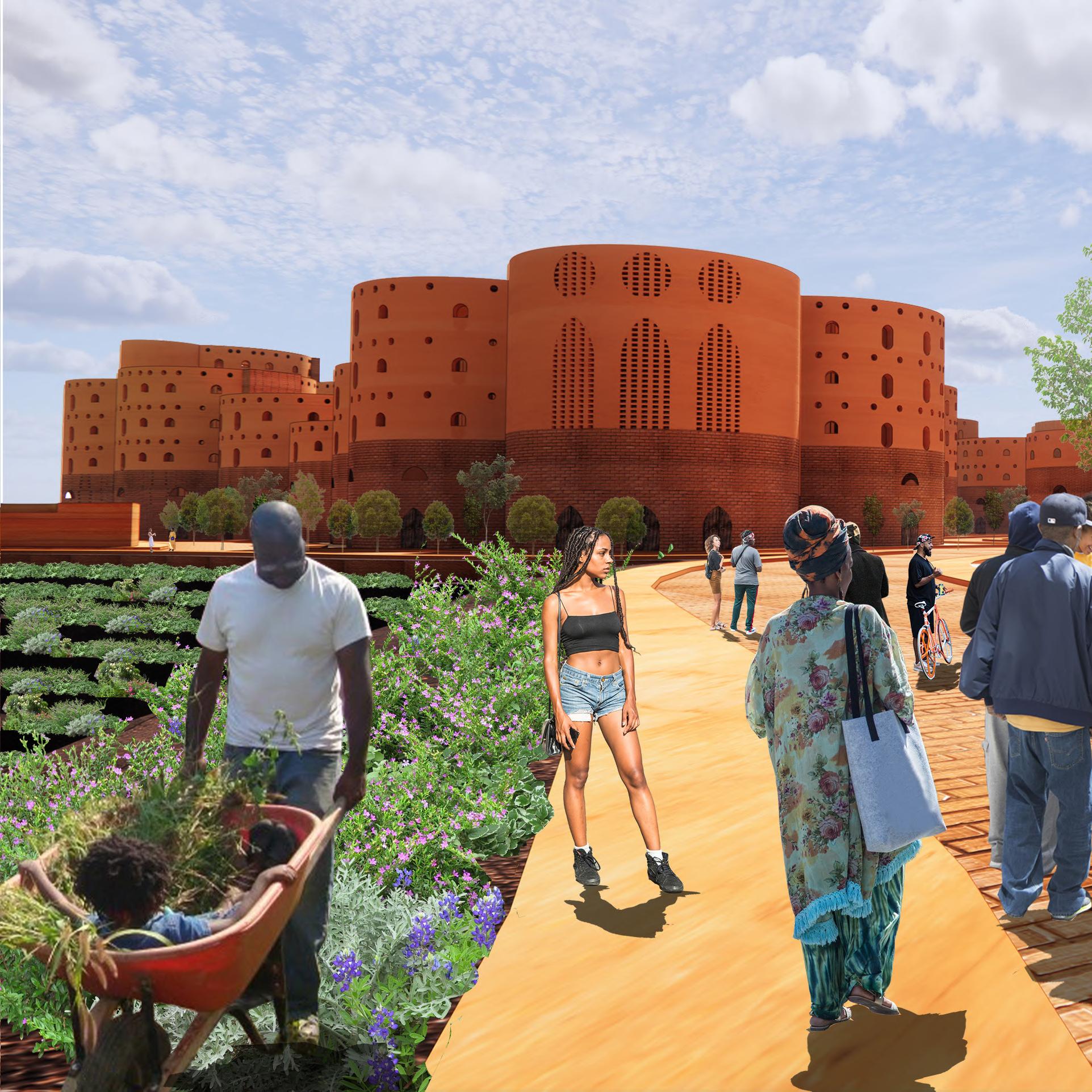


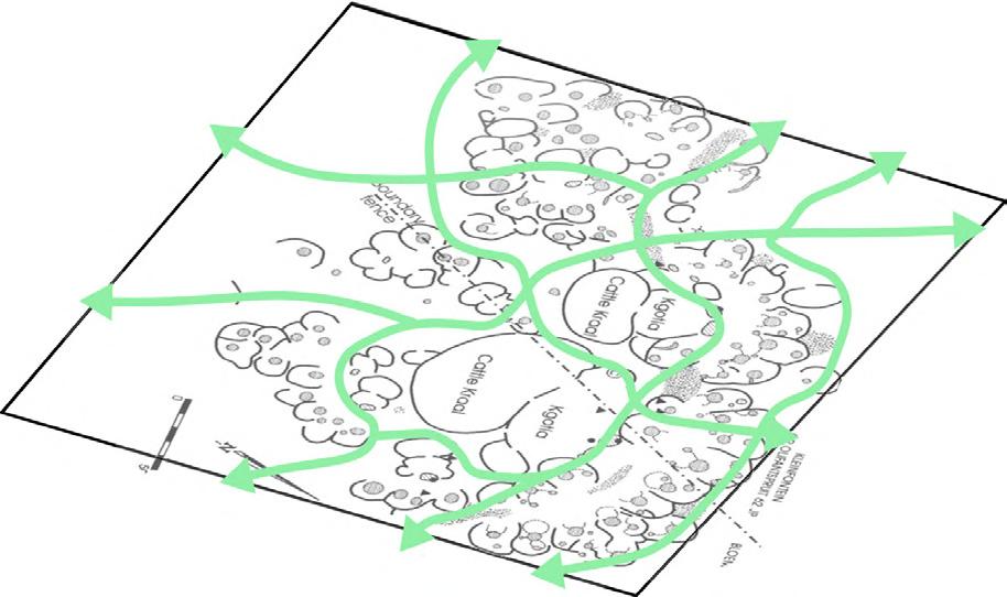
Mapping footpaths to generate circulation through site
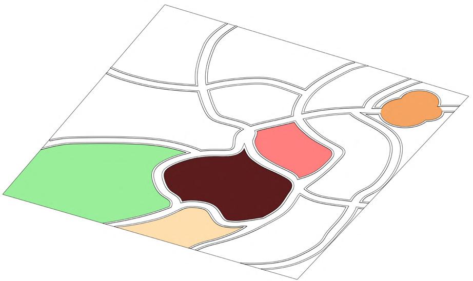


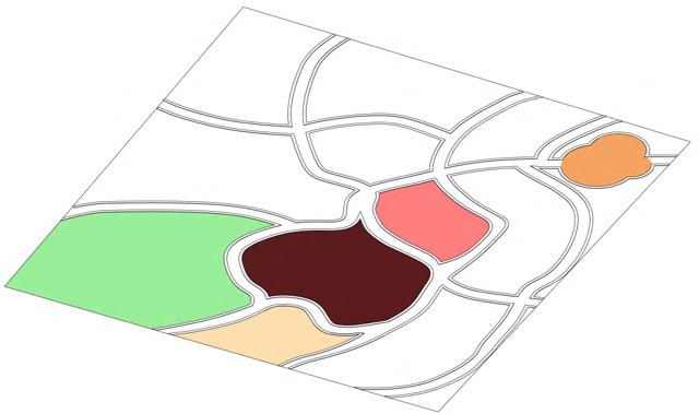
Public spaces designated throughout master plan
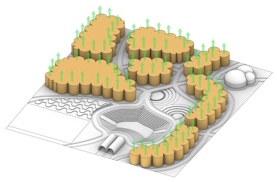
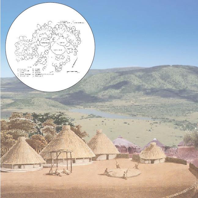
Foot prints raised and massing generated
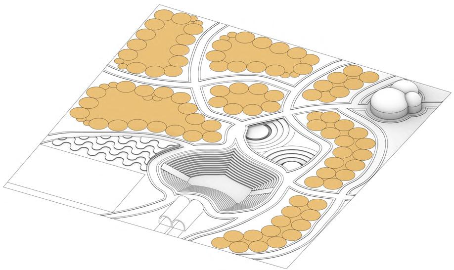
Housing foot print developed based on circular units
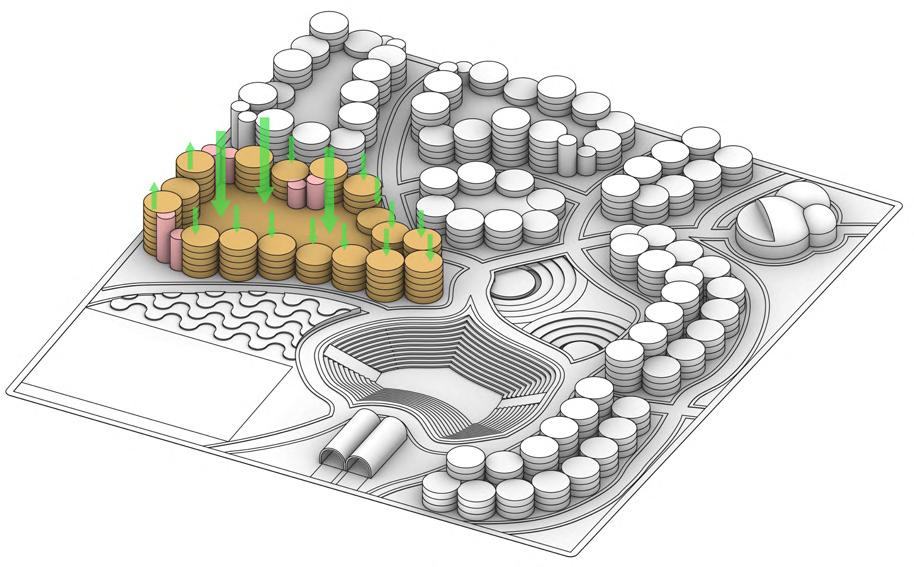
Pushing and pulling of mass for increased sun exposure and generation of communal space
Football Field/ Seating Terraced Farm Garage Library Ampitheatre
2.
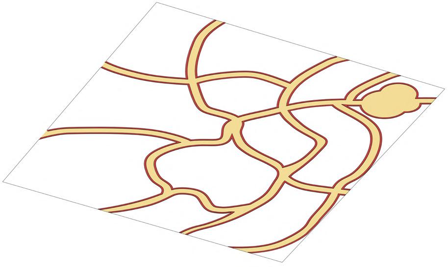
Walkways and Sidewalks generated
PROGRAM PLANS
Retail Housing
Communal Kitchen
Egress
2nd story Podium
Breezway
Lobby
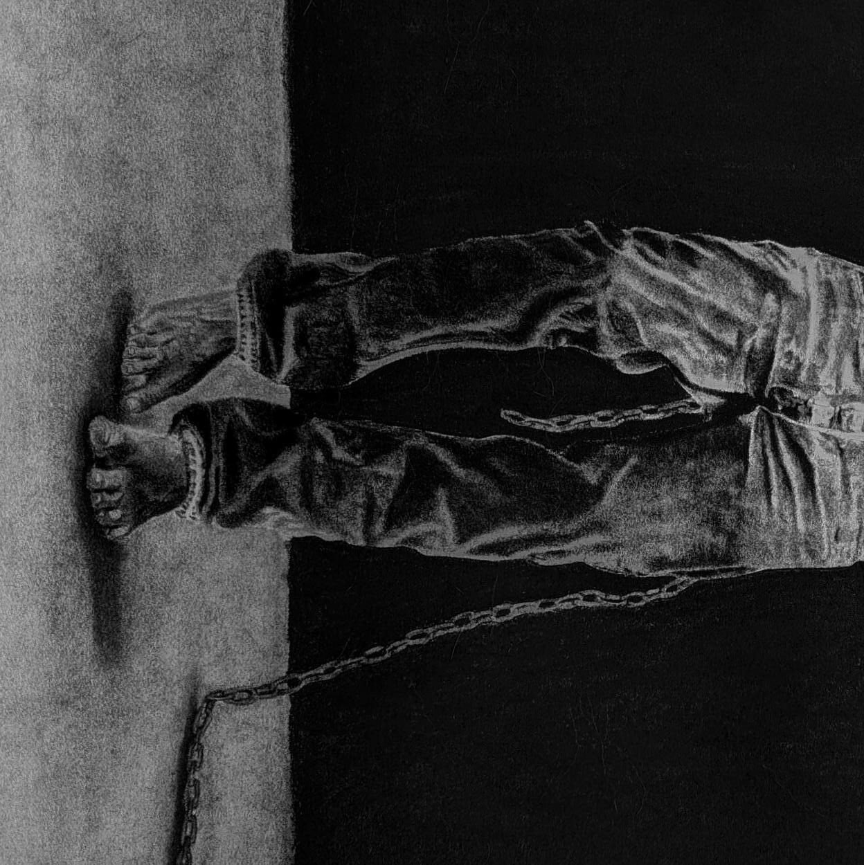
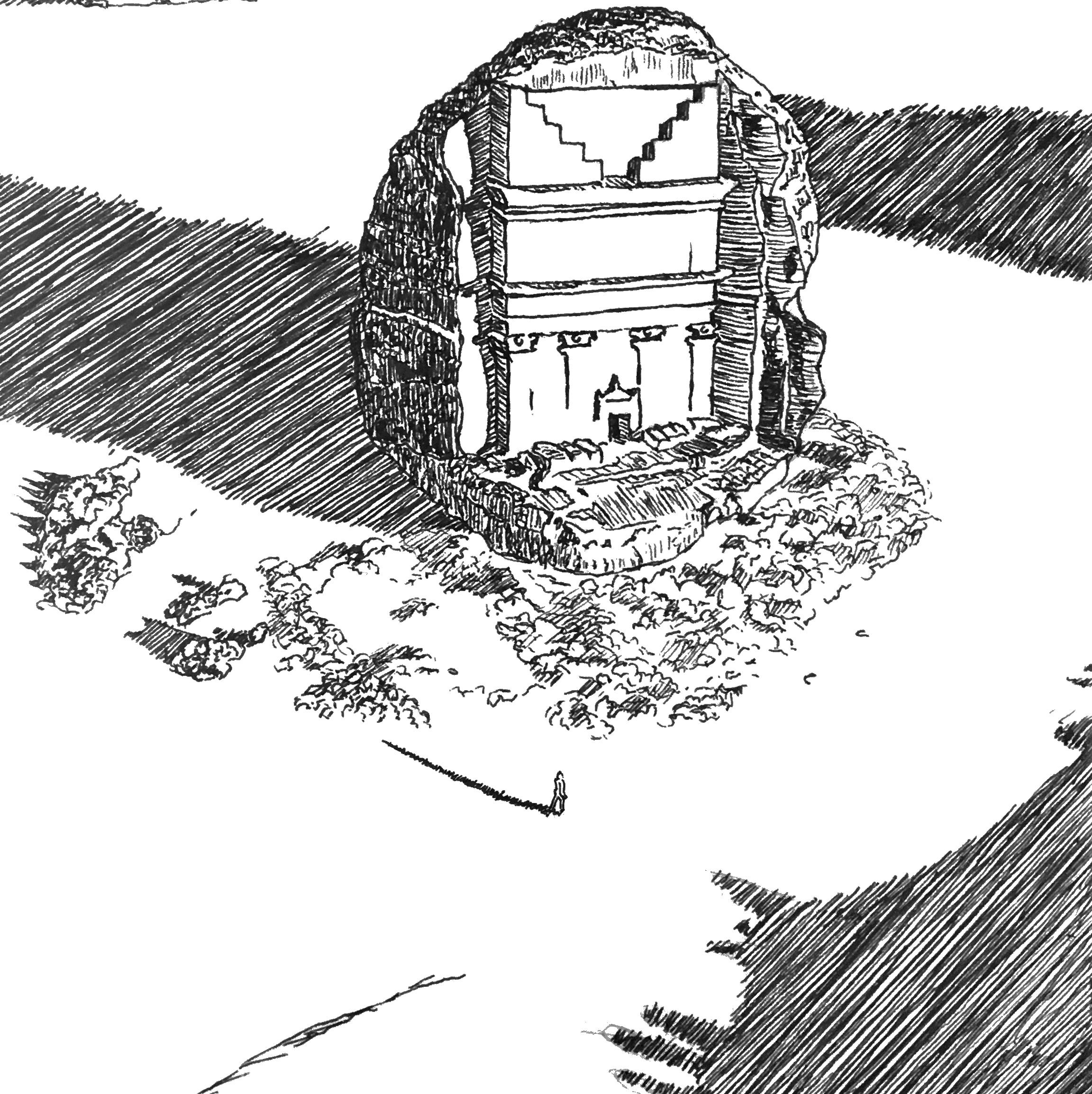
Personal Work

My Drawings...