
Engine Tier 3 introduction
Self
Pilot
Pilot
Pilot
Self
Pilot
Pilot
Self
Pilot
Pilot
Pilot
Self
Pilot
Pilot
Pilot

Document Title: Function Group: Information Type: Date: Engine for MC60B and MC70B, description 200
Service Information 2014/3/20
Profile:
SSL, MC60B [GB]
Go back to Index Page
Engine for MC60B and MC70B, description
The engine is a vertical in-line, four cylinder, four stroke, water-cooled diesel engine with a direct injection system. The engine for MC70B is also equipped with a turbocharger of radial flow type. The valve mechanism receives its movement from the camshaft via rods and rocker arms. Turning direction is counter-clockwise seen from the flywheel. Firing order is 1-3-4-2 and the first cylinder is on the flywheel side.

The fuel system is direct injection via a rotary high pressure pump, a so called MP pump. It has only one plunger cylinder to pressurize the fuel and a distribution shaft which regulates the fuel flow to each cylinder. The lubrication system consists of forced lubrication with a trochoid pump. The air system consists of a dual element, self cleaning air cleaner. The cooling of the engine is performed by a high capacity radiator and a hydraulic oil cooler. The type of fluid used in the cooling system consists of 50% ethylene glycol and 50% water, which gives an anti-freeze protection.

Document Title: Function Group: Information Type:
Date:
Engine, description 200 Service Information 2014/3/20
Profile:
SSL, MC60B [GB]
Go back to Index Page
Engine, description
MC60B (D2.2DCBE3)
The engine is a vertical in-line, four cylinder, four stroke, water-cooled diesel engine with a direct injection system. The valve mechanism receives its movement from the camshaft via rods and rocker arms. Turning direction is counter-clockwise seen from the flywheel. Firing order is 1-3-4-2 and the first cylinder is on the flywheel side.

The fuel system is fed by an electric fuel pump that supplies the fuel to the (mechanical) fuel injection pump. The lubrication system consists of forced lubrication with a trochoid pump.
The air system consists of a dual element, self cleaning air cleaner.
The cooling of the engine is performed by a high capacity radiator and a hydraulic oil cooler. For type of fluid used in the cooling system, see section 260 Engine cooling system, specification
Document Title: Function Group: Information Type: Date: Engine, removing 210 Service Information 2014/3/20
Profile: SSL, MC60B [GB]
Go back to Index Page
Engine, removing
Op nbr 210-070
11668023 Lifting tool
9993902 Disassembly tool

9993903 Disassembly tool
WARNING
Hot oil and hot engine coolant can cause severe burns!
NOTICE
Always handle oils and other environmentally hazardous fluids in an environmentally safe manner.
1. Put the machine in service position 1, see 191 Service position 1
2. Switch the battery master switch off.
3. Open the drain valve and drain the coolant to a suitable container.

5. When the radiator is drained, close the drain valve

6. Applies to engine equipped with high flow: Open the drain valve and drain the hydraulic oil in a suitable container.
8. Remove the screw, moulding, stop, clamps and cover that holds the engine cover onto the chassis.
9. Remove the engine cover from the crossmember.
 Figure 2
7. Remove the gas spring from the upper radiator support.
Figure 3
1. Gas spring
Figure 2
7. Remove the gas spring from the upper radiator support.
Figure 3
1. Gas spring
NOTE!
Some
may still be
 Figure 4
1. Engine cover mounting
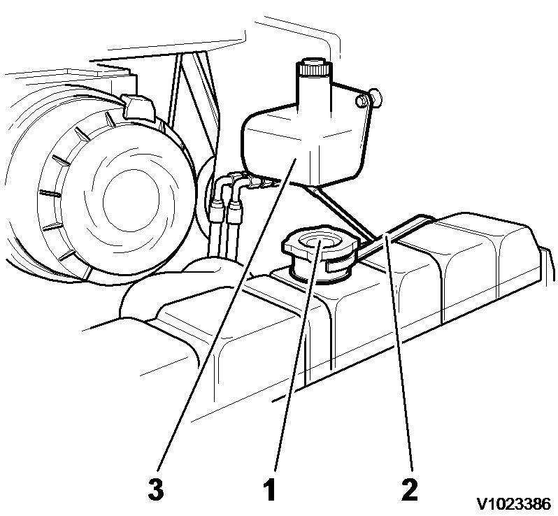
10. Disconnect the radiator overflow hose from the radiator and drain the overflow bottle into the container.
Figure 5
1. 2. 3.
Radiator fill cap Over flow hose Over flow bottle
11. Transfer the coolant to a container with a cover and label the container as "Used Antifreeze". Dispose of the coolant at an approved recycling facility.
12. Disconnect and plug up the return hose from the hydraulic cooler. Use 9993902 Disassembly tool and 9993903 Disassembly tool.
hydraulic oil
in the system.
Figure 4
1. Engine cover mounting
10. Disconnect the radiator overflow hose from the radiator and drain the overflow bottle into the container.
Figure 5
1. 2. 3.
Radiator fill cap Over flow hose Over flow bottle
11. Transfer the coolant to a container with a cover and label the container as "Used Antifreeze". Dispose of the coolant at an approved recycling facility.
12. Disconnect and plug up the return hose from the hydraulic cooler. Use 9993902 Disassembly tool and 9993903 Disassembly tool.
hydraulic oil
in the system.


 Figure 6
13. Disconnect and plug up the swivel connection on the right side of the radiator.
Figure 7
14. Unbolt the cable from oil cooler.
15. Open the latches holding the cooling assembly together. Lift the oil cooler from the radiator. Carefully place the oil cooler on a flat surface.
Figure 8
1. 2. Oil cooler Radiator
Figure 6
13. Disconnect and plug up the swivel connection on the right side of the radiator.
Figure 7
14. Unbolt the cable from oil cooler.
15. Open the latches holding the cooling assembly together. Lift the oil cooler from the radiator. Carefully place the oil cooler on a flat surface.
Figure 8
1. 2. Oil cooler Radiator
 3. 4. Cable Latch
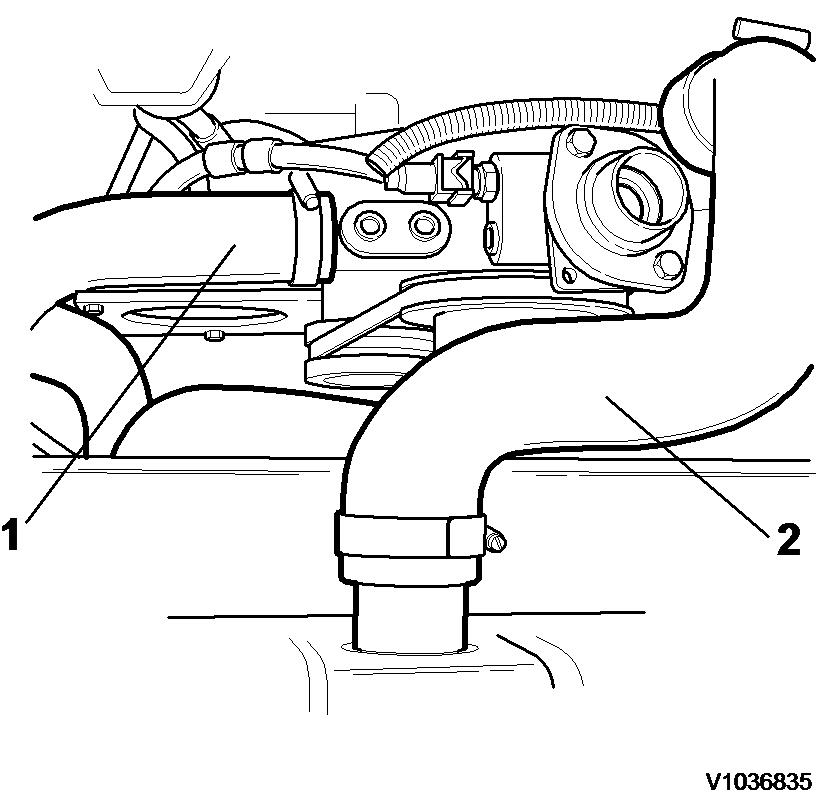
16. Disconnect the upper radiator hose from the engine block.
Figure 9
17. Remove the fan guard.
18. Disconnect the lower radiator hose from the engine block.
Figure 10
1. 2. Lower radiator hose Upper radiator hose
19. Remove the locknuts and the washers from the bottom of the radiator.
20. Remove the capscrews, washers and locknuts from the top of the radiator.
3. 4. Cable Latch
16. Disconnect the upper radiator hose from the engine block.
Figure 9
17. Remove the fan guard.
18. Disconnect the lower radiator hose from the engine block.
Figure 10
1. 2. Lower radiator hose Upper radiator hose
19. Remove the locknuts and the washers from the bottom of the radiator.
20. Remove the capscrews, washers and locknuts from the top of the radiator.
NOTE!
Use care when handling the
assembly. To prevent damage to the radiator drain valve, do not place the


on its bottom surface without support blocks used on each side.
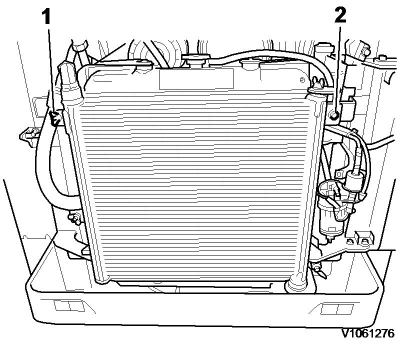
 Figure 11
1. 2. Lower radiator mounts Upper radiator mounts
21. Carefully lift the radiator assembly.
radiator/oil cooler
radiator
Figure 12
22. Disconnect the wires to the air cleaner restriction sensor.
Figure 13
Figure 11
1. 2. Lower radiator mounts Upper radiator mounts
21. Carefully lift the radiator assembly.
radiator/oil cooler
radiator
Figure 12
22. Disconnect the wires to the air cleaner restriction sensor.
Figure 13
23. Loosen the hose clamp that secures the air intake hose to the engine induction manifold and remove the intake hose. Plug or cover the induction manifold intake port to prevent entry of dirt or debris into the engine. Remove the air cleaner assembly out of the frame. Engine equipped with turbo remove the hose between air cleaner and turbo charger. NOTE!
Remove the hose between the air cleaner and the turbo charger on engines equipped with turbo.

24. Loosen the capscrews holding the muffler and the capscrews holding the exhaust mainfold. On engine equipped with turbo remove the exhaust manifold between muffler and turbo charger.
 1. Restriction sensor
Figure 14
Picture shows MC60B
Figure 15
1. 2. Muffler Exhaust manifold
25. Remove the muffler assembly.
1. Restriction sensor
Figure 14
Picture shows MC60B
Figure 15
1. 2. Muffler Exhaust manifold
25. Remove the muffler assembly.


 Figure 16
Picture shows MC70B
26. Disconnect the engine harness from the main chassis harness.
Figure 17
27. Tag and remove the wires from the positive (+) terminal on the starter.
Figure 18
1. 2. 3.
Positive (+) terminal Starter flange Negative (-) cable
Figure 16
Picture shows MC70B
26. Disconnect the engine harness from the main chassis harness.
Figure 17
27. Tag and remove the wires from the positive (+) terminal on the starter.
Figure 18
1. 2. 3.
Positive (+) terminal Starter flange Negative (-) cable
28. Tag and remove the negative (-) cable and ground wire from the starter flange.


 29. Tag and remove the wire to the alternator.
Figure 19
30. Tag and remove the wire to the pre-heater.
Figure 20
1. Pre-heater
31. Close the valve on the fuel supply line at the water separator.
Figure 21
29. Tag and remove the wire to the alternator.
Figure 19
30. Tag and remove the wire to the pre-heater.
Figure 20
1. Pre-heater
31. Close the valve on the fuel supply line at the water separator.
Figure 21


 1. Crane fuel supply
32. Tag, disconnect and plug the fuel supply– and fuel return line at the engine block.
Figure 22
1. 2. Fuel return Fuel supply
33. Disconnect the throttle cable from the fuel injection pump lever.
Figure 23
1.
2. Throttle cable Govenor lever
34. Applies to engine equipped with high flow. Remove the high flow hoses.
1. Crane fuel supply
32. Tag, disconnect and plug the fuel supply– and fuel return line at the engine block.
Figure 22
1. 2. Fuel return Fuel supply
33. Disconnect the throttle cable from the fuel injection pump lever.
Figure 23
1.
2. Throttle cable Govenor lever
34. Applies to engine equipped with high flow. Remove the high flow hoses.
35. Connect the lifting equipment 11668023 to the front (1) and rear (2) lift eyes. Remove all slack in the lift equipment to prevent the engine from unintended movement during removal of the engine mounting hardware.


NOTE!
The engine must be lifted using an overhead or frame type hoist and lift sling or frame, rated at a minimum capacity of 500 kg (1100 lb)
Figure 24 Figure 25 36. Remove capscrews from the rear engine mount. Figure 26 37. Remove the capscrews from the front engine mount.38. Lift and move the engine slightly toward the rear of the machine until the transmission universal drive joint drops free of the splined transmission drive shaft. Weight, approximately: 240 kg (530 lb)
39. Slowly and carefully lift the engine from the machine.

40. Place the engine on engine stands or similar, strong and stable enough to support the weight of the engine. NOTE!
If this engine is to be replaced, it may be necessary to remove all the hardware that will be used on the replacement engine. These components may not be included with the replacement engine.
 Figure 27
Figure 28
Figure 27
Figure 28
Document Title: Function Group: Information Type: Date:
Engine, removing 210 Service Information 2014/3/20
Profile: SSL, MC60B [GB]
Go back to Index Page
Engine, removing
Op nbr 210-070
11668023 Lifting tool
WARNING
Hot oil and hot engine coolant can cause severe burns!
NOTICE
Always handle oils and other environmentally hazardous fluids in an environmentally safe manner.
1. Park the machine in service position 1, see 191 Service position 1
2. For lifting the loader arm when engine is not running see 191 Manual lifting of loader arm
3. Switch of the battery.
4. Open the drain valve and drain the coolant to a suitable container.

5. Carefully open the fill cap on the radiator to speed up the draining.
6. When the radiator is drained, close the drain valve
7. Transfer the coolant to a container with a cover and label the container as "Used Antifreeze". Dispose of the coolant at an approved recycling facility.
8. Remove the right cover over the engine.
9. Remove the gas spring from the lower support.

10. Remove the engine cover from the crossmember.
11. Disconnect the radiator overflow hose from the radiator. Secure the hose so that the coolant remains in the over flow bottle.
 Figure 2
1. Coolant drain hose
Figure 3
1. 2. Engine cover Right side cover
Figure 2
1. Coolant drain hose
Figure 3
1. 2. Engine cover Right side cover
 Figure 4
1. 2. 3.
Radiator fill cap Over flow hose Over flow bottle
12. Disconnect and plug up the hydraulic hose on the left side of the radiator.
Figure 5
13. Disconnect the upper radiator hose from the engine block.
Figure 6
Figure 4
1. 2. 3.
Radiator fill cap Over flow hose Over flow bottle
12. Disconnect and plug up the hydraulic hose on the left side of the radiator.
Figure 5
13. Disconnect the upper radiator hose from the engine block.
Figure 6
1. 2. Lower radiator hose Upper radiator hose
14. Disconnect the lower radiator hose from the engine block.

15. Disconnect the two hoses for cab heating from the engine (Option).
1. Hose for cab heating
16. Remove the fan guard.
17. Remove the capscrews, locknuts and the washers from the radiator.
18. Close the valve on the fuel supply line at the water separator.
Figure 7 Figure 8 1. 2. Capscrews Capscrews

 Figure 9
1. Fuel line supply
19. Carefully lift the radiator and oil cooler assembly aside
Figure 10
20. Disconnect the fuel filter hoses.
Figure 11
21. Disconnect the cable connection to the air cleaner restriction sensor (SE2501).
Figure 9
1. Fuel line supply
19. Carefully lift the radiator and oil cooler assembly aside
Figure 10
20. Disconnect the fuel filter hoses.
Figure 11
21. Disconnect the cable connection to the air cleaner restriction sensor (SE2501).
Suggest:
If the above button click is invalid.
Please download this document first, and then click the above link to download the complete manual.
Thank you so much for reading


 Figure 12
1. Cable connection
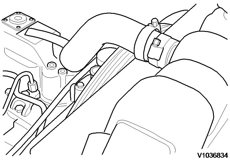
22. Loosen the hose clamp for the air intake hose. Plug or cover the pre heating to prevent entry of dirt or debris into the engine.
Figure 13
1. Hose clamp
23. Remove the air cleaner assembly out of the frame.
Figure 12
1. Cable connection
22. Loosen the hose clamp for the air intake hose. Plug or cover the pre heating to prevent entry of dirt or debris into the engine.
Figure 13
1. Hose clamp
23. Remove the air cleaner assembly out of the frame.

 Figure 14
24. Remove the four nuts that connects the exhaust system (one not visible on picture).
Figure 15
1. 2. 3.
Exhaust system nut Exhaust system nut Exhaust system nut
25. Remove the capscrews holding the muffler and remove the muffler assembly.
Figure 16
1. 2. 3. 4.
Capscrew Capscrew Capscrew Capscrew
26. Disconnect the engine harness from the main chassis harness.
Figure 14
24. Remove the four nuts that connects the exhaust system (one not visible on picture).
Figure 15
1. 2. 3.
Exhaust system nut Exhaust system nut Exhaust system nut
25. Remove the capscrews holding the muffler and remove the muffler assembly.
Figure 16
1. 2. 3. 4.
Capscrew Capscrew Capscrew Capscrew
26. Disconnect the engine harness from the main chassis harness.