
Document Title: Function Group: Information Type: Date:
Engine, description 200 Service Information 2014/7/2 0
Profile:
EXC, EC360B LC [GB]
Go back to Index Page
Engine, description
Machine serial no. EC330B: 10001 ~ 10235, EC360B: 10001 ~ 10828
The engine is a straight six cylinder, four stroke, direct injection diesel with 9.6 liter cylinder volume, turbocharged, inter cooled and electronic controlled fuel injection, EMS (Engine Management System), with a cast iron block and cylinder head. The cylinder block and head are designed with internal passages formed as sets for lubrication and cooling.

An engine driven power take off for a hydraulic pump can be provided for the D10 as extra equipment
Structure, fuel filter side view
Engine, fuel filter side view
Fuel feed pump
Fuel filter
Engine oil filter (bypass)
EMS (Engine Management System)
Fuel inlet
Water outlet
Engine PTO (Power Take Off)
Fan drive and pulley

Oil cooler
Engine oil filter (full)
Breather
Structure, turbocharger side view
Fuel pump
Turbocharger


Cooler block heater (1 3/4″ -16UN - 2B)
Cab heater supply (1/2″ - 14UPSI)
Engine lifting eye
Coolant filter heater (1/2″ - 14UPSI)
Starter
Fuel shut off solenoid
Dipstick
Oil drain valve
Oil pan
Coolant filter return (M 22 × 1.5)
Cab heater return (M 22 × 1.5)
Structure, top view
Figure 2Engine, top view


Air intake port Oil filter (bypass) Coolant vent Air exhaust port
Structure, front side view
Engine, front side view
Dipstick gauge Water inlet Alternator
Structure, rear side view
1. 2. 3. 4. Figure 4 1. 2. 3. Figure 5Engine, rear side view
1. 2. 3. 4. Fuel filter Oil filter (bypass) Oil cooler Flywheel housingDocument Title: Function Group: Information Type: Date:
Engine, description 200 Service Information 2014/7/2 0
Profile:
EXC, EC360B LC [GB]
Go back to Index Page
Engine, description
Machine serial no. EC330B: 10236 ~ 10712, EC360B: 10829 ~ 12151
D12C EC(D,E)E2 is the model number of the volvo 12 liter engine for the EC330B/360B excavator.
The engine is a 6-cylinder, 4-stroke, direct injection diesel with a 12 liter cylinder volume, turbocharger, charged air cooler and electronic controlled fuel injection, EMS (Engine Management System).
The serial number of the engine is to be found stamped in the cylinder block on the rear left side.
The cylinder head is of cast iron and manufactured in one piece which is necessary in order to provide stable bearings for the overhead camshaft.
The cylinder liner is sealed against the coolant casing with rubber rings.
The D12C EC(D,E)E2 has a four-valve system and overhead camshaft.
The engine timing gear transmission is located at the front of the engine on a 10 mm thick steel plate bolted to the cylinder block.
The crankshaft is drop forged and has induction hardened bearing surfaces and fillets.
The engine is force fed lubricated by an oil pump which is gear driven from the engine crankshaft via an intermediate gear
The fuel system for D12C EC(D,E)E2 has electronic control with unit injectors one for each cylinder and which operate at a very high pressure.
The fuel feed pump is a gear driven type and is driven from the engine timing gear with the same gear.
Engine, structure

 Figure 1

 Figure 2
Document Title: Function Group: Information Type: Date:
Engine, description 200 Service Information 2014/7/2 0
Profile:
EXC, EC360B LC [GB]
Go back to Index Page
Engine, description
Machine serial no. EC330B: 10713 ~ , 80001 ~ , EC360B: 12152 ~ , 80001 ~
D12DEBE2 and D12DEBE3 are the model number of the Volvo 12 liter engine.
The engine is a 6-cylinder, 4-stroke, direct injection diesel with a 12 liter cylinder volume, turbocharger, charged air cooler and electronic controlled fuel injection, EMS (Engine Management System).
The serial number of the engine is to be found stamped in the cylinder block on the rear left side.
The cylinder head is of cast iron and manufactured in one piece which is necessary in order to provide stable bearings for the overhead camshaft.
The cylinder liner is sealed against the coolant casing with rubber rings.
The D12DEBE2 and D12DEBE3 have a four-valve system and overhead camshaft.
The engine timing gear transmission is located at the front of the engine on a 10 mm thick steel plate bolted to the cylinder block.
The crankshaft is drop forged and has induction hardened bearing surfaces and fillets.
The engine is force fed lubricated by an oil pump which is gear driven from the engine crankshaft via an intermediate gear
The fuel system for D12DEBE2 and D12DEBE3 have electronic control with unit injectors one for each cylinder and which operate at a very high pressure.
The fuel feed pump is a gear driven type and is driven from the engine timing gear with the same gear.
 Figure 1
 Figure 2
Document
Profile:
EXC, EC360B LC [GB]
Basic check, Engine
NOTE!
Certain tests and checks are performed with unlocked safety locking lever. Make sure that the machine cannot operate unexpectedly when the safety locking lever is unlocked.
Purpose of the basic check
The purpose of the basic check is to provide fast and accurate information about the general condition of the engine. The basic check should be performed and evaluated according to instructions in the PC-tool VCADS Pro. Tests included in the basic check
The basic check which is divided into the following tests should be performed after reading out error codes and checking parameters
Tests:
1.
Cylinder compression, test
The purpose of the test is to show if any cylinder has a deviating compression pressure. The test replaces the old pressure check method but does not give any absolute values.
2.
Cylinder balancing, test
The purpose of the test is to show if there is any deviation in the fuel injection to a cylinder.
3. 4.
Feed pressure, test
The purpose of the test is to check that the feed pressure is as per specification. Sensor, test
The purpose of the test is to check the function of all sensors.
Troubleshooting
General about troubleshooting
When a malfunction is suspected or has been confirmed, it is important to identify the cause as soon as possible. The starting point for all troubleshooting is that there is some type of trouble symptom or malfunction. Malfunctions can be indicated by:
generation of error codes detection of a malfunction symptom.
Troubleshooting work
The first step in troubleshooting is to gather information from the operator concerning the malfunction symptoms, see Electrical and information system, Collection of basic data. Then, attempt to pin-point the cause by checking in a certain order, for more information, see Electrical and information system, troubleshooting strategy. The different checking steps are:
Check error codes
Check parameters
Perform basic check
Troubleshooting information
The following is included in Electrical and information system and is used when troubleshooting:
Troubleshooting strategy
Describes troubleshooting work, step by step.
Troubleshooting, assistive devices
Brief summary of the assistive devices that are available for troubleshooting.
Functional checks and tests, VCADS Pro
Brief description of VCADS Pro. For a detailed description, see VCADS Pro User’s Manual.
Error code information
Contains information regarding error code design, lists of all error codes and error code information about each error code.
Components, troubleshooting and specifications
Contains methods and measuring values for troubleshooting of components. Also includes wiring diagrams and certain specifications. Parameters
Incorrectly set parameters may cause malfunction symptoms. The parameter list includes all limit and command values for parameters.
Control units, functional description
Describes the functions of the control units, inputs and outputs as well as communication between the various control units.
Control units, active and passive measuring
Contains measuring values for active and passive measuring of the ECUs.
Software functions
Describes the pre-requisite conditions for the control and monitoring functions that are performed by the software in the ECUs.
Profile: EXC, EC360B LC [GB]
Valves, adjusting

Op nbr 214-012
88820003 Setting tool 9993590 Gear wheel
Feeler gauge
WARNING
Risk of burns - stop the diesel engine and allow it to cool down before starting any work.

1. Place the machine in service position B. See 091 Service positions
2. Open the engine hood.
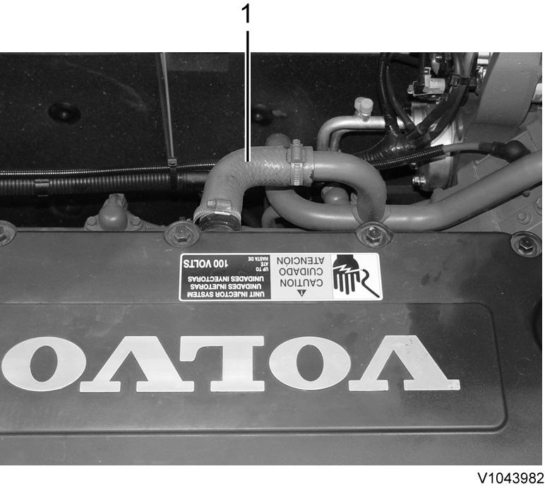
3. Remove step (1).
4. Remove crankcase ventilation hose (1).
5.
Removal, crankcase ventilation hose
Adjusting inlet valve
7. Turn the flywheel with tool 9993590 until the nearest dash marking on the camshaft is between the marks on the bearing cap.

NOTE!
The number identifies the cylinder for which both inlet and exhaust valves are in correct position for adjusting.

NOTE!
Cylinder 1 is closest to the engine timing gear.
Figure 2 Remove valve cover (1). Figure 3 Removal, valve cover 6. Remove the protective cover on the flywheel housing and install tool 9993590, an extension and a ratchet handle. Figure 4 9993590, extension and ratchet handle8. Loosen lock nut (2) on the rocker arm and adjust screw (1) to get the correct valve clearance according to and tighten the lock nut. Tightening torque: see 214 Valve mechanism, double rocker arm


214 Valve mechanism, tightening torques
9. Loosen lock nut (2) on the rocker arm and adjust screw (1) to get the correct valve clearance according to and tighten the lock nut. Tightening torque: see 214 Valve mechanism, double rocker arm
214 Valve mechanism, tightening torques
 Figure 5 Camshaft marking
Figure 6
1. 2. 3.
Adjusting screw Lock nut Feeler gauge
Adjusting exhaust valve
Figure 5 Camshaft marking
Figure 6
1. 2. 3.
Adjusting screw Lock nut Feeler gauge
Adjusting exhaust valve
10. Check-measure the valve clearance according to . 214 Valve mechanism, double rocker arm NOTE!

Before checking the double rocker arm's clearance, check that the exhaust valve clearance is correct according to . 214 Valve mechanism, double rocker arm
Checking, double rocker arm (IEGR)
11. Loosen the drain nipple and drain air and oil from the double rocker arm.
 Figure 7
1. 2. 3.
Adjusting screw Lock nut Feeler gauge
Figure 8
Figure 7
1. 2. 3.
Adjusting screw Lock nut Feeler gauge
Figure 8
12. Insert the go-side of gauge 88820003 between the double rocker arm's contact surface and the camshaft's basic circle. The go-side must be able to pass between the arm contact surface and the camshaft, if the IEGR-"lift" is not too great.

13. Insert the stop-side of 88820003 between the double rocker arm's contact surface and the camshaft's basic circle. The stop-side must not be able to pass between the contact arm surface and the camshaft. If it does, the IEGR-"lift" is too small.
NOTE!
If the go-side of the gauge passes between the double rocker arm's contact surface and the camshaft's basic circle and if the stop-side does not, the clearance for the double rocker arm is correct. If not, the double rocker arm must be adjusted as follows:
14. Tighten the drain nipple. Tightening torque: see 214 Valve mechanism, tightening torques
15. Adjust the other valves and check-measure the double rocker arm clearance in the same way.
NOTE!
The drain nipple on the double rocker arm must be open during the adjustment procedure.
1. Draining nipple Figure 9 Go-and-stop gauge 88820003 1. 2. Stop-side of gauge Go-side of gaugeSuggest:
If the above button click is invalid.
Please download this document first, and then click the above link to download the complete manual.
Thank you so much for reading

Sleeve
Nipple
Lock nut
Piston
Adjusting, double rocker arm (IEGR)
16. Keep the camshaft in the same position as when adjusting the valve clearance. Hold piston (7) and loosen lock nut (6) with an Allen head wrench.
17. Insert adjusting tool 88820003 between the double rocker arm's contact surface and the camshaft's basic circle. Turn piston (7) with an Allen key so that zero clearance is obtained between the double rocker arm, the tool, and the camshaft.


NOTE!
Zero clearance means that the adjusting tool does not slide smoothly between the double rocker arm and the camshaft.
18. Tighten lock nut (6) while firmly holding piston (7) in the correct position. Tightening torque: see 214 Valve mechanism, tightening torques
Figure 10 Double rocker arm 1. 2. 3. 4. 5. 6. 7. Follower arm (IEGR-rocker arm) Exhaust rocker arm Stop nut Figure 11 Adjusting tool 88820003