
Structural Analysis 9th Edition Hibbeler Solutions Manual Full Download: http://testbanktip.com/download/structural-analysis-9th-edition-hibbeler-solutions-manual/
© 2014 Pearson Education, Inc., Upper Saddle River, NJ. All rights reserved. This material is protected under all copyright laws as they currently exist. No portion of this material may be reproduced, in any form or by any means, without permission in writing from the publisher.
2–1. The steel framework is used to support the reinforced stone concrete slab that is used for an office. The slab is 200 mm thick. Sketch the loading that acts along members BE and FED. Take a = 2 m , b = 5 m . Hint: See Tables 1.2 and 1.4.
Solution
Beam BE. Since b a = 5 m 2 m = 2.5, the concrete slab will behave as a one-way slab. Thus, the tributary area for this beam is rectangular, as shown in Fig. a, and the intensity of the uniform distributed load is
200 mm thick reinforced stone concrete slab: (23.6 kN>m3)(0.2 m)(2 m) = 9.44 kN>m
Live load for office: (2.40 kN>m2)(2 m) = 4.80 kN > m 14.24 kN > m
Due to symmetry the vertical reactions at B and E are B y = E y = (14.24 kN>m)(5)>2 = 35.6 kN
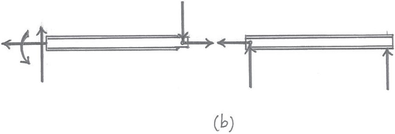
The loading diagram for beam BE is shown in Fig. b
Ans.
Beam FED. The only load this beam supports is the vertical reaction of beam BE at E, which is E y = 35.6 kN. The loading diagram for this beam is shown in Fig. c


ThisworkisprotectedbyUnitedStatescopyrightlaws andisprovidedsolelyfortheuseof instructorsinteachingtheircoursesandassessingstudentlearning. Disseminationor saleofanypartofthiswork(includingontheWorldWideWeb) willdestroytheintegrityoftheworkandisnotpermitted.
Beam BE. Since b a = 4 3 6 2, the concrete slab will behave as a two-way slab. Thus, the tributary area for this beam is the hexagonal area shown in Fig. a, and the maximum intensity of the distributed load is

200 mm thick reinforced stone concrete slab: (23.6 kN > m3)(0.2 m)(3 m) = 14.16 kN > m
Live load for office: [(2.40 kN>m2)(3 m)] = 7.20 kN > m
21.36 kN > m Ans.
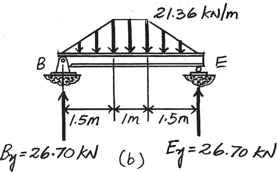
Due to symmetry, the vertical reactions at B and E are B y = Ey = 2 c 1 2 (21.36 kN > m)(1.5 m) d + (21.36 kN > m)(1 m) 2 = 26.70 kN
The loading diagram for beam BE is shown in Fig. b
Beam FED. The loadings that are supported by this beam are the vertical reaction of beam BE at E which is E y = 26.70 kN and the triangular distributed load of which its tributary area is the triangular area shown in Fig. a. Its maximum intensity is

200 mm thick reinforced stone concrete slab: (23.6 kN > m3)(0.2 m)(1.5 m) = 7.08 kN > m
Live load for office: (2.40 kN > m2)(1.5 m) = 3.60 kN > m
10.68 kN > m
The loading diagram for beam FED is shown in Fig. c
Ans.
andisprovidedsolelyfortheuseof instructorsinteachingtheircoursesandassessingstudentlearning.
2–3. The floor system used in a school classroom consists of a 4-in. reinforced stone concrete slab. Sketch the loading that acts along the joist BF and side girder ABCDE. Set a = 10 ft , b = 30 ft . Hint: See Tables 1.2 and 1.4.
Solution
Joist BF. Since b a = 30 ft 10 ft = 3, the concrete slab will behave as a one-way slab. Thus, the tributary area for this joist is the rectangular area shown in Fig. a, and the intensity of the uniform distributed load is
4-in.-thick reinforced stone concrete slab: (0.15 k > ft3) a 4 12 ft b (10 ft) = 0.5 k > ft

Live load for classroom: (0.04 k > ft2)(10 ft) = 0.4 k > ft 0.9 k > ft Ans.
Due to symmetry, the vertical reactions at B and F are B y = F y = (0.9 k > ft)(30 ft) > 2 = 13.5 k Ans.
The loading diagram for joist BF is shown in Fig. b

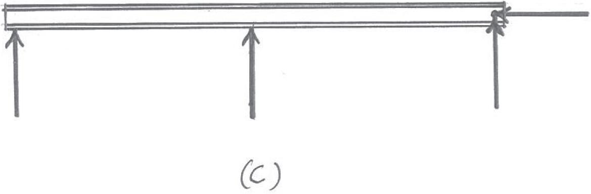
Girder ABCDE. The loads that act on this girder are the vertical reactions of the joists at B, C, and D, which are B y = C y = D y = 13.5 k. The loading diagram for this girder is shown in Fig. c


ThisworkisprotectedbyUnitedStatescopyrightlaws andisprovidedsolelyfortheuseof instructorsinteachingtheircoursesandassessingstudentlearning. Disseminationor saleofanypartofthiswork(includingontheWorldWideWeb) willdestroytheintegrityoftheworkandisnotpermitted.
*2–4. Solve Prob. 2–3 with a = 10 ft, b = 15 ft
Solution
Joist BF. Since b a = 15 ft 10 ft = 1.5 < 2, the concrete slab will behave as a two-way slab. Thus, the tributary area for the joist is the hexagonal area, as shown in Fig. a, and the maximum intensity of the distributed load is

4-in.-thick reinforced stone concrete slab: (0.15 k > ft3) a 4 12 ft b (10 ft) = 0.5 k > ft
Live load for classroom: (0.04 k > ft2)(10 ft) = 0.4 k > ft
Due to symmetry, the vertical reactions at B and G are
The loading diagram for beam BF is shown in Fig. b
Girder ABCDE. The loadings that are supported by this girder are the vertical reactions of the joist at B, C and D, which are B y = C y = D y = 4.50 k, and the triangular distributed load shown in Fig. a. Its maximum intensity is


4-in.-thick reinforced stone concrete slab: (0.15 k > ft3) a 4 12 ft b (5 ft) = 0.25 k > ft
Live load for classroom: (0.04 k > ft2)(5 ft) = 0.20 k > ft 0.45 k > ft
The loading diagram for the girder ABCDE is shown in Fig. c
ThisworkisprotectedbyUnitedStatescopyrightlaws andisprovidedsolelyfortheuseof instructorsinteachingtheircoursesandassessingstudentlearning. Disseminationor saleofanypartofthiswork(includingontheWorldWideWeb) willdestroytheintegrityoftheworkandisnotpermitted.
© 2014 Pearson Education, Inc., Upper Saddle River, NJ. All rights reserved. This material is protected under all copyright laws as they currently exist. No portion of this material may be reproduced, in any form or by any means, without permission in writing from the publisher.
2–5. Solve Prob. 2–3 with a = 7.5 ft, b = 20 ft
Solution
Beam BF. Since b a = 20 ft 7.5 ft = 2.7 7 2, the concrete slab will behave as a one-way slab. Thus, the tributary area for this beam is a rectangle, as shown in Fig. a, and the intensity of the distributed load is
4-in.-thick reinforced stone concrete slab: (0.15 k > ft3) a 4 12 ft b (7.5 ft) = 0.375 k > ft

Live load from classroom: (0.04 k > ft2)(7.5 ft) = 0.300 k > ft 0.675 k > ft Ans.
Due to symmetry, the vertical reactions at B and F are
B y = Fy = (0.675 k > ft)(20 ft)
2 = 6.75 k Ans.
The loading diagram for beam BF is shown in Fig. b
Beam ABCD. The loading diagram for this beam is shown in Fig. c.


ThisworkisprotectedbyUnitedStatescopyrightlaws andisprovidedsolelyfortheuseof instructorsinteachingtheircoursesandassessingstudentlearning. Disseminationor saleofanypartofthiswork(includingontheWorldWideWeb) willdestroytheintegrityoftheworkandisnotpermitted.
2–6. The frame is used to support a 2-in.-thick plywood floor of a residential dwelling. Sketch the loading that acts along members BG and ABCD. Set a = 6 ft, b = 18 ft Hint: See Tables 1.2 and 1.4.
Solution
Beam BG. Since b a = 18 ft 6 ft = 3 7 2, the plywood platform will behave as one-way slab. Thus, the tributary area for the beam is rectangular and shown shaded in Fig. a. The intensity of the uniform distributed load is


2-in.-thick plywood platform: a 36 lb ft3 ba 2 12 ft b ( 6 ft ) = 36 lb > ft

Live load for residential dwelling: a 40 lb ft2 b ( 6 ft ) = 240 lb > ft 276 lb > ft Ans.
Due to symmetry, the vertical reaction at B and G are
B y = Gy = ( 276 lb > ft )( 18 ft ) 2 = 2484 lb Ans.
The loading diagram for beam BG is shown in Fig. b.
Beam ABCD. The loads that act on this beam are the vertical reaction of beams BG and CF at B and C respectively, which are Cy = B y = 2484 lb. The loading diagram of this beam is shown in Fig. c.
ThisworkisprotectedbyUnitedStatescopyrightlaws andisprovidedsolelyfortheuseof instructorsinteachingtheircoursesandassessingstudentlearning. Disseminationor saleofanypartofthiswork(includingontheWorldWideWeb) willdestroytheintegrityoftheworkandisnotpermitted.
2–7. Solve Prob. 2–6, with a = 10 ft, b = 10 ft
Solution
Beam BG. Since b a = 10 ft 10 ft = 1 6 2, the plywood platform will behave as a two-way slab. Thus, the tributary area for this beam is the shaded square area shown in Fig. a, and the maximum intensity of the triangular distributed load is


2-in.-thick plywood platform: a 36 lb ft3 ba 2 12 ft b ( 10 ft ) = 60 lb > ft
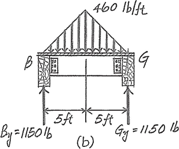
Live load for residential dwelling: a 40 lb ft2 b ( 10 ft ) = 400 lb > ft 460 lb > ft Ans.
Due to symmetry, the vertical reaction at B and G are B y = Gy =
1 2 ( 460 lb > ft )( 10 ft ) 2 = 1150 lb Ans.
The loading diagram for beam BG is shown in Fig. b
Beam ABCD. The loadings that are supported by this beam are the vertical reaction of beams BG and CF at B and C respectively, which are B y = Cy = 1150 lb and the triangular distributed load contributed by the dotted triangular area shown in Fig. a Its maximum intensity is
2-in.-thick plywood platform: a 36 lb ft3 ba 2 12 ft b ( 5 ft ) = 30 lb > ft
Live load for residential dwelling: a 40 lb ft2 b ( 5 ft ) = 200 lb > ft 230 lb > ft Ans.
The loading diagram for beam ABCD is shown in Fig. c
Beam ABCD. 1150 lb at B and C, w max = 230 lb > ft
ThisworkisprotectedbyUnitedStatescopyrightlaws andisprovidedsolelyfortheuseof instructorsinteachingtheircoursesandassessingstudentlearning. Disseminationor saleofanypartofthiswork(includingontheWorldWideWeb) willdestroytheintegrityoftheworkandisnotpermitted.
*2–8. Solve Prob. 2–6, with a = 10 ft, b = 15 ft
Solution
Beam BG. Since b a = 15 ft 10 ft = 1.5 6 2, the plywood platform will behave as a two-way slab. Thus, the tributary area for this beam is the shaded octagonal area shown in Fig. a, and the maximum intensity of the trapezoidal distributed load is


2-in.-thick plywood platform: a 36 lb ft3 ba 2 12 ft b ( 10 ft ) = 60 lb > ft
Live load for residential dwelling: a 40 lb ft2 b ( 10 ft ) = 400 lb > ft
Due to symmetry, the vertical reactions of B and G are B y = Gy =
1 2 ( 460 lb > ft )( 15 ft + 5 ft )
The loading diagram for beam BG is shown in Fig. b
Beam ABCD. The loadings that are supported by this beam are the vertical reactions of beam BG and CF at B and C respectively which are B y = Cy = 2300 lb, and the triangular distributed load contributed by the dotted triangular area shown in Fig. a. Its maximum intensity is
2-in.-thick plywood platform:
36
Live load for residential dwelling: ( 40 lb > ft2 ) (5 ft) = 200
The loading diagram for beam ABCD is shown in Fig. c.
ThisworkisprotectedbyUnitedStatescopyrightlaws andisprovidedsolelyfortheuseof instructorsinteachingtheircoursesandassessingstudentlearning. Disseminationor saleofanypartofthiswork(includingontheWorldWideWeb) willdestroytheintegrityoftheworkandisnotpermitted.
2–9. The steel framework is used to support the 4-in. reinforced stone concrete slab that carries a uniform live loading of 400 lb > ft2. Sketch the loading that acts along members BE and FED. Set a = 9 ft, b = 12 ft. Hint: See Table 1.2.


Solution
Beam BE. Since b a = 12 ft 9 ft = 4 3 6 2, the concrete slab will behave as a two-way slab. Thus, the tributary area for this beam is the shaded octagonal area shown in Fig. a, and the maximum intensity of the trapezoidal distributed load is

Due to symmetry, the vertical reactions at B and E are
The loading diagram of beam BE is shown in Fig. a
Beam FED. The loadings that are supported by this beam are the vertical reactions of beam BE at E, which is Ey = 15.19 k and the triangular distributed load contributed by dotted triangular tributary area shown in Fig. a. Its maximum intensity is
The loading diagram of beam FED is shown in Fig. c.
ThisworkisprotectedbyUnitedStatescopyrightlaws andisprovidedsolelyfortheuseof instructorsinteachingtheircoursesandassessingstudentlearning. Disseminationor saleofanypartofthiswork(includingontheWorldWideWeb) willdestroytheintegrityoftheworkandisnotpermitted.
2–10. Solve Prob. 2–9, with a = 6 ft, b = 18 ft
Solution
Beam BE. Since b a = 18 ft 6 ft = 3 7 2, the concrete slab will behave as a one-way slab. Thus, the tributary area for this beam is the shaded rectangular area shown in Fig. a, and the intensity of the uniform distributed load is

4-in.-thick reinforced stone concrete slab: ( 0.15 k > ft3 ) a 4 12 ft b (6 ft) = 0.30 k > ft
Floor live load: ( 0.4 k > ft2 ) (6 ft) = 2.40 k > ft 2.70 k > ft
Due to symmetry, the vertical reactions at B and E are
B y = Ey = ( 2.70 k > ft ) (18 ft) 2 = 24.3 k
The loading diagram of beam BE is shown in Fig. b.
Beam FED. The only load this beam supports is the vertical reaction of beam BE at E, which is Ey = 24.3 k

The loading diagram of beam FED is shown in Fig. c

ThisworkisprotectedbyUnitedStatescopyrightlaws andisprovidedsolelyfortheuseof instructorsinteachingtheircoursesandassessingstudentlearning. Disseminationor saleofanypartofthiswork(includingontheWorldWideWeb) willdestroytheintegrityoftheworkandisnotpermitted.
2–11. Classify each of the structures as statically determinate or indeterminate. If indeterminate, specify the degree of indeterminacy.

Solution
(a) r = 3 3(1) = 3
Statically determinate Ans.
(b) r = 5 3(1) 6 5
Statically indeterminate to the second degree Ans.
(c) r = 6 3(2) = 6
Statically determinate Ans.
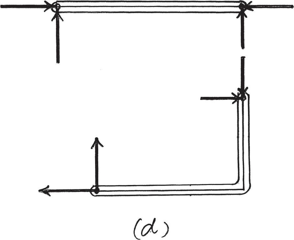
(d) r = 10 3(3) 6 10

Statically indeterminate to the first degree Ans.
(e) r = 7 3(2) 6 7
Statically indeterminate to the first degree Ans.

*2–12. Classify each of the frames as statically determinate or indeterminate. If indeterminate, specify the degree of indeterminacy. All internal joints are fixed connected.

Solution
r = 6 3n = 3(1) = 3
r - 3n = 6 - 3 = 3
Stable and statically indeterminate to third degree.
r = 12 3n = 3(2) = 6
r - 3n = 12 - 6 = 6
Stable and statically indeterminate to sixth degree.
r = 5 3n = 3(2) = 6
r 6 3n
Unstable.
Unstable since the line of action of the reactive force components are concurrent.


ThisworkisprotectedbyUnitedStatescopyrightlaws andisprovidedsolelyfortheuseof instructorsinteachingtheircoursesandassessingstudentlearning.
2–13. Classify each of the structures as statically determinate, statically indeterminate, stable, or unstable. If indeterminate, specify the degree of indeterminacy. The supports or connections are to be assumed as stated.

Stable and statically indeterminate to first degree.
(b) r = 6 3n = 3(2) = 6 r = 3n
Stable and statically determinate
Stable and statically indeterminate to first degree
andisprovidedsolelyfortheuseof instructorsinteachingtheircoursesandassessingstudentlearning.
2–14. Classify each of the structures as statically determinate, statically indeterminate, stable, or unstable. If indeterminate, specify the degree of indeterminacy. The supports or connections are to be assumed as stated.


Solution
(a) r = 5 3n = 3(2) = 6
r 6 3n
Unstable
(b) r = 9 3n = 3(3) = 9
r = 3n
Stable and statically determinate
(c) r = 8 3n = 3(2) = 6
r - 3n = 8 - 6 = 2
Stable and statically indeterminate to the second degree
© 2014 Pearson Education, Inc., Upper Saddle River, NJ. All rights reserved. This material is protected under all copyright laws as they currently exist. No portion of this material may be reproduced, in any form or by any means, without permission in writing from the publisher.

2–15. Classify each of the structures as statically determinate, statically indeterminate, stable, or unstable.


Solution
(a) Unstable (support reactions concurrent) Ans.
(b) r = 3 3n = 3(1) = 3
(c)
Statically determinate Ans.
r = 3 3n = 3(1) = 3
Statically determinate Ans.
ThisworkisprotectedbyUnitedStatescopyrightlaws andisprovidedsolelyfortheuseof instructorsinteachingtheircoursesandassessingstudentlearning. Disseminationor saleofanypartofthiswork(includingontheWorldWideWeb) willdestroytheintegrityoftheworkandisnotpermitted.
Solution
(a) r = 6 3n = 3(1) = 3
r - 3n = 6 - 3 = 3
*2–16. Classify each of the structures as statically determinate, statically indeterminate, or unstable. If indeterminate, specify the degree of indeterminacy. (a)
Stable and statically indeterminate to the third degree


(b) r = 4 3n = 3(1) = 3
r - 3n = 4 - 3 = 1
Stable and statically indeterminate to the first degree
(c) r = 3 3n = 3(1) = 3 r = 3n
Stable and statically determinate
(d) r = 6 3n = 3(2) = 6 r = 3n
Stable and statically determinate
© 2014 Pearson Education, Inc., Upper Saddle River, NJ. All rights reserved. This material is protected under all copyright laws as they currently exist. No portion of this material may be reproduced, in any form or by any means, without permission in writing from the publisher.

Solution
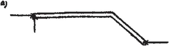
a)
r = 9, n = 3
2–17. Classify each of the structures as statically determinate, statically indeterminate, or unstable. If indeterminate, specify the degree of indeterminacy. (a) (b)


r = 3n 9 = 3(3)
Statically determinate Ans.
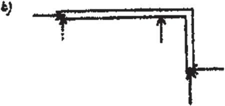
b)
r = 12, n = 4
r = 3n 12 = 3(4)
Statically determinate Ans.
c)
r = 3, n = 1
r = 3n 3 = 3(1)
Stable and statically determinate Ans.
d)
r = 5, n = 2
r 6 3n

5 6 3(2)
Unstable Ans. (d)
ThisworkisprotectedbyUnitedStatescopyrightlaws andisprovidedsolelyfortheuseof instructorsinteachingtheircoursesandassessingstudentlearning.
saleofanypartofthiswork(includingontheWorldWideWeb) willdestroytheintegrityoftheworkandisnotpermitted.
*2–18. Determine the reactions on the beam.

Solution
Equations of Equilibrium. Referring to the FBD of the beam in Fig. a, A y and By can be determined directly by writing the moment equations of equilibrium about B and A respectively.
a+ M B = 0; 60(10) + 120(15) - A y (30) = 0 A y = 80.0 k Ans.
a+ M A = 0; B y (30) - 120(15) - 60(20) = 0 B y = 100 k Ans.
Write the force equation of equilibrium along x axis,
S + Fx = 0; B x = 0 Ans.
andisprovidedsolelyfortheuseof
theircoursesandassessingstudentlearning.

ThisworkisprotectedbyUnitedStatescopyrightlaws andisprovidedsolelyfortheuseof instructorsinteachingtheircoursesandassessingstudentlearning.
