
Honda Cb900f 919 Service Manual Converted Full download: http://manualplace.com/download/honda-cb900f-919-service-manual-converted/ This is the cut pages sample. Download all 432 page(s) at: ManualPlace.com

The ser vice and repai r information conta ined in this manual is intended for use by qualified, profess iona l technicians Attempting service o rr epairs without the proper t raining, tools, and equipment could cause i njury to you or others. It could also damage theveh icle orcreateanunsafe condition .
Th is manual describes the pr ope r methods and procedu res for perform ing serv ice, maintenance , andr epairs.S ome procedures require the use of specially designed tools and dedicated equipment Any pe rson who intends to usea replacement part, service procedure ora tool that i snot r ecommendedbyHonda , must determine ther isks to their personal safety andthesafe operation of the vehicle.
If you needtor eplace a part use gen uine Honda parts with t he correc t part numbe r o r an equivalen t part West rong ly r ecommend that you do not use replaceme nt parts of inferior qu ality.
Properse rv ice a nd maint enancearee ssentialt o th e cu sto mer's safety and the re liabili ty o f the vehicle Any error o r oversig ht w hile servic ing ave hicle ca n resu lt in faul ty ope ration, damage tot he veh icle, or injury to others
Because this manual is i ntended for the profess ional service technician , we do not p rov ide warn ings about many bas ic shop safety p racti ces(e g ., Hot parts - wear glo ves). If you ha ve not received shop safety tra in ing ordo not feel confident about your knowledge of safe serv icing practice, we recommended that y oudo not attempt to perform the procedures described i n this manua l.
S ome of the most important genera l service safety preca utions are given be low. However, we cannot wa rn yo u of eve ry conceiva ble hazard that canar isei npe rforming service a nd re pair p rocedure s O nly yo u ca n decide w hether o rn ot you s hould pe rfor m a give n t ask.
Improper se rvice o rr epairsc an c reate a nun safe co ndi tion t hat can cause you r custo me r or others tobese rious ly hurt orki lled
Follow the procedures and precautions in this manual and o the r service materials carefully

Failureto prope rly fo llow inst ructions and p recautions canc ause you tobe serious ly h urt or k illed
Foll ow the proce dures and p recautionsinth is ma nual ca refully.
•
•
Make s ure yo uh avea clear u nderstanding o fallbas ic s hop sa fe ty p ractices andt hat you a re wear ing ap propr iate c lothing using safety equ ipment When per forming any serv icet ask, b e especia lly careful of the f ollowing:
Readall of the in structions before yo u beg in, and make sure you have the tools, the replacement or repair parts , and the sk ills required to perform the tasks safely and completely.
Protect your eyes by using proper safety glasses goggles o r face shields any time you hammer, d rill grind pry or wo rk around pressur ized a ir or liquids , and springs or other stored-energy components If there is any doubt, put oneye protection
Use other protective wear w hen necessary, for examp le g loves or safety shoes. Handling hot o r sha rp parts ca n cause severe bu rns o r c uts Before you grab someth ing that l ooks like itcan h urt you stop and p ut on gloves
Protect you rself a nd ot hers wheneve r you have the vehicle up i nt he ai r Any time yo u lift the vehicle , e ithe r wit h a h oisto r ajack, make su re that it i sa lways secure ly supported Use j ack stands
M akesu re t he e nginei so ff be fore yo ub eg in a ny se rv ic ing p rocedures, u nlessth e in structionte lls yo u to doo t herwise. ,. This will h elpe lim inate severa l pote ntialh azards : ,.
Carbon mo nox ide poisoning from engi ne exhaust. Be sure t hereis adequate ve ntila tion wheneve r you run t he engine
Burns from hot parts or coo lant Let the engine and exhau st system cool before working in those area s I njury from moving parts . If the inst ruction te lls you to run the engine , be sure you r hands, fingers and clot hing are out the way
Gasoline v ap orsand hydrogen gases from batter ies are explosive To reduce the poss ibility of a f ireor exp losion, be careful w hen working around gasol ine or batter ies
Use only a nonflammable solvent, not gasoline , to clean p arts
Ne ver drain or store gasoline inan open container
Keepall cigarettes. sparks andf lames away from the battery and all fuel -related parts.
Thisserv ice manual descr ibes the service procedures for theCB900F.

Follow t he Maint enance Sched u le (Sect ion 3) recommendat ionsto e nsure thatth e vehicle is i npeakope rating condition
Perfo rming the fir st schedu led maintenanc e i s ver y important. It compensatesfo r thein itialw ear that occurs during thebreak -in per iod.
Sect ions 1 and3 apply to the w hole motorcycle Sect ion 2i llustrates procedures for remo val/ins tallation of components that ma y be r equiredto p erfo rm se rv ice descr ibed inthe follo wing sect ions Sect ions 4 through 19 descr ibep artsofth e moto rcycle,g rouped according to lo cation.
Find the section y ou want on t hispage.then t urntothe table ofcont ents on t he first pageof that section
Most sect ions start w ithan assemb ly o r systemi llustration,se rvice informationand trou bles hoot ing forthe se ct i on.Thesub sequent pagesg ive detailed proc edu re.
Ifyou don't kno w the source of the trouble, gotosect ion 22, Troub leshoot ing
Your safety,andthesaf ety of others, isvery important. To help youmake inform ed decisions weha ve p rovided safety messages and other informatio n thro ugho ut th is manual. Of course, it i s not pract ical orposs ible towarnyou about allthehazard s assoc iated with se rvic ing th is v eh i cle. Youm ust us e your o wn good judgemen t. Youw ill find impo rtant safety informa tion inava r iety offo rms i ncluding: • SafetyLabe ls- onthe vehic le •Safety M essages-prece ded bya safety a lert symbol &. andoneof thr ee s ignal words, DANGER, WARNING, o r CA UTION These signal w ords mean :
YouW ILL be KILLEDorSERIOUSLY HURT if you don't fo llo wi nstructions.
YouCANbeKILLED o r SERIOUSLY H URT if you d on't f o ll ow i nst r uctions.
: ou b e HURTifyou don't follow Instruct ions
•Inst ructions - how to serviceth is veh icle co rrectly andsafel y.
T he symbo ls u sed thr oughoutt his ma nual sho w speci fic se rv ice proced ures Ifs upple me ntary in for mation isre quired perta i ning to the sesy mbols, it w ill beexpl ained speci fica lly i n the te xtw ithout t he us eo fthe symbo ls.
Replacet he partts) wi th new onets) beforeasse m bly ""jill "71
U set he recommended e ngine oil , u n less otherwise spec ified ,
U se m olybdenumoi lsolution( m ixt ure o f thee ngi ne o il a nd moly bdenum grease in a ratio of 1:1 ) .. w::Ji
U se multi -pur pose grease ( Lithiumbased multi-purpos eg reaseNLGI # 2 oreq uivalent
U se m olybdenum d isulfideg rease (co ntai ning mo reth an3% m olybdenumd isulfide , NLGI # 2 or equ ivalent
Examp l e : BR-2p lus man ufactured by Dow Corn ing U S.A MUlti-purpose M -2 manufact ured by Mitsu bishi O il, Japan
Use mo lybde num d isu lfide paste (con tain ing more t han40% molybden um d is ulfide , N LGI # 2 o r equ iva lent
Ex ample : M olvkote" G- n Pastema n ufact ured by Do wCo rningU.S.A.
Honda Mol y 60(U S.A. o nly)
Rocol ASPm anufactured byRocol Li mited , U .K.
Rocol Pasteman ufactured by Sumico Lubri cant , Jap an
U se silicone grease
A p p lya l ocki ng agent .U sea medium strength l ocki ngag ent un less otherw ise s pecified
App lys eal ant
UseDOT4 b rakef luid Usethe r ecommen dedbra ke f l uid unles s ot herwise speci fied
Use fork or suspens ion fluid

SERV ICE RULES
1-1 LUBRICATION &SEALPOINTS 1 -18
MODEL IDENTIFICATION 1-2 CABLE& HARNESS ROUTING 1 -22 III SPECIFICATIONS 1-3 EMISSION CONTROL SYSTEMS 1-35
TORQUE VALUES 1-12 EMISSION CONTROL I NFORMATION
TOOLS 1-17 LABELS 1 -38
1. U segen uine Hondao r Ho n da-r ecommended pa rts and l u bricantsor their e q uiva lents Parts that d on 't m eetHo nda's desig n specifications may cause dama ge tothe moto rcycle.
2.Usethe specia l too ls designed fo r t his prod uct t o avoid da mage a ndi ncorrect assemb ly.
3.Use only m etric tools whe n se rv icing the motorcycle Met ric bolts. nuts andsc rews a re not interchangeable with English fasteners .
4 Install new gaskets , O-rings. cotte r pins , and lockp lates whe n reassembling.
5 When tightening bolts or n uts, begin wi th t he larger diameter or i nner bolt fi rst T hen tighten tothe specified torque diagonally in i ncre mental steps unless a p articular sequence is specified
6 .Clean parts i nclea ning solvent upon disassembly Lubricatea ny s l iding surfaces b eforereasse mb ly.
7. After reassembly, checka ll parts fo r proper in stallat ion a nd o pera tion
8. Routealle lectrical w ires ass hown o np ages through 1-32, Cable and Harn ess Routing
T he engine serial number is stamped on the r ight s ide of the u pper crankcase.
T heVehic leIdentification N umber(VIN)is located on the left s ide of the f rame near the steer ing head.

T he frame serial number i sst amped on the r ightside of the steering head.
The throttle body identification number i s stamped on the intake side of the throttle body as shown
T he color label is attached a s shown. When ordering color-coded parts, always specify the designated color code

Overall length
Overall width
Overal l height
Wheelbase Seathe ight
Footpeg height
Ground c learance
Dry weight
Curb weight
FRAM E
Except Ca l ifornia type
California type
Except California type Ca lifornia type
Ma ximum we ight capac ity
Frame type
Front suspe nsion
Front axle trave l
Rear suspension
Rear axle travel
Frontt ire size
Reart ire size
F ront tire brand
Reart ire brand
Front brake
Rear brake
Caster ang le
Tra il leng th
Fueltank capacity
Cylinder arrangement
Boreandstroke
D isplacement
Compress ion ratio
Valvetrai n
Intake va lve opens f at 1mm closes10.04in) l ift
Exhaust valve opens closes
Lubrication system
Oil pump type
Coo ling system
Air filtrat ion
Enginedry we ight
F iring order
2,125mm183.7 inl 7 50 mm 12 9 .5 in) 1,085 mm 142.7 inl 1,460 mm 157 5 i nl 795 mm 131.3 inl 345 mm 113.6 inl 145 mm 15.7 in) 194kg1428 lbs) 195kg(430Ibs) 2 18kg(481 Ibs) 219kg(483Ibs) 174kg(384Ibs) D iamond Te lescopic fork 109 mm (4 .3 in) Swingarm 128 mm (4.7 inl 120/70ZR 17 158WI,120/70ZR 17 M/C158WI 180/55ZR 17 173WI,180/55 ZR 17M /C 173WI BT56FRADIALN( Bridgestonel T X15 (Michelini BT56RRAD IALG (Bridgestonel T X25 (Michelin)
Hydraulic double disc H ydraulic single disc 2 5' 98 mm (3 .9 in) 19.0 liter (5 .02 U S gal, 4 18 Imp gall
4cy linders in- line, i nclined 3 0 ° from vertica l 71 .0 X58.0 mm 12.80X2.28 in) 919em ' 156.1 cu-in) 10.8 : 1
Chain driven, DO HC 10' BTDC 30 ' A BDC 35 ' BBDC 5' ATDC
Forced pressure and wet sump Trochoid Liquid cooled Paper element 68kg(150Ibs) 1 -2 -4-3
CAR BURATIDN Type
PGM- FI (Programm edFuelI njection)
Throttle bore 36 mm (1.4 i n)
DRIVE TRAIN Clutchsystem
Multi-plate, wet Clutch operation system Cableope rating
Transmiss ion Consta nt mesh, 6-speeds
Primary reduction 1 52(76/50)
Final reduct ion 2.688 (43/16)

Gear ratio 1st 2.769 (36/13) 2nd 2.0 00126/13) 3rd 1.600 12 4/15) 4th 1.368 126/19) 5th 1.227 127/22) 6th 1.130 126/23)
Gearshift pattern Left foot operated return system , 1-N-2-3-4- 5 - 6
ELECTRICAL
Ignition system
Starting system
C hargingsystem
Regu lator/rectifier
Computer-controlled digita l transistorized withelectricadvance
E lectric starter motor
T riplephase output alternator
SCR shorted/tr iple phase,full wave rect ification
Lightingsystem Battery
Engineoil capaci ty
Recommended eng ine oil
Unit: m ml inl
A fterd rai ning 3 .5 l it er(3 7USqt, 3 1 I mpqt )
Aft er dra ining/filte rc ha nge 3 .6 l i ter(3 .S USqt , 3 .2 I mpqt )
After di sass emb ly 4.4l i ter ( 4 6 U Sqt 3.9 Imp q t) --
Pro H ond a G N4o rHP4 (wit hout m olybde num ad dit ives ) 4-stroke oil I USA & Canada). or H onda 4-str okeo i l (Ca na d a only) , o ra n equi valent motor o il A PI se rvice c lassif ication SG or H igher e xcept oi ls labe led as e nergy conserv ing on the API se rvice la bel. JASO T9 03 st andard MA Viscosit y : SAE10W -40
O il pr essureat o ilp ressu re switch
Oil pump ro tor
490 kPa (5.0 kgf/c m ' , 71psi )at -6,000 min" ( rpm) /(SO ' C/ 176 ' F)
Tip cl earan ce 0 .15 10 006) 0 .20 (O.OOS )
Body cl earance 0 .15 -0 .2210.006-0 .009) 0.3510.014 1 Side cl earance 0 .02 -0 .07 10.001 -0 .003) 0 .10 10.0041
Throttle b ody identifi c ation Except California type GQ34C number Californ ia type GQ34B
Starterva lve v acuum diffe rence 2664 Pa 120 mm Hg i Base thr ottlev alvef orsy nchronization No .2 Id lespeed 1,200 ± 100rni n' Ir pm )
Thr ottl eg rip free pl ay 2 - 4 mm (1/16 - 3/16 in)
Int akeai rt e mper aturese n sor re sist ance (at20 'C/6S 0F ) 1 -4 kn
Engine coo lant tempe rature sen sor resistance (at 20"Cl68"F ) 2.3 - 2 .6 kn
Fueli njec to r resistance (at 20'C /6 S'F ) 11.1-12.3 11
PAIR so lenoid v alvere sis tan ce(at20 'C/68'F ) 20 - 24 n
Camp ulse genera tor peak voltage (at 20 'C/68 'F) 0 .7Vm inimum
Ignit ionpu lsege nerator p eak vo ltage l at 20 'C /68'F ) 0 7 Vm i nimum Man ifold ab so l ute p ressure at i d le 200-250 mm H g
Fuelpr essure at idle 343 k Pa 13 5 k gf /c m ', 50p si)
Fuel p u mp flow (at12 V) 256 em ' (S 7US OZ, 9 .0 Imp OZ) mi n imum/1 0seconds

Coo lant capacity
ITEM SPE CI FICATION S
Radiatorand e n gi n e
3 .2 liter 13 38US qt 2 .82 Im p qt )
Reserve tank 0 .8 liter (0. 8 5US q t. 0 70 Imp q tl Rad iatorca p rel iefpr essure 10 8 -137kPa 11 1 - 1.4 kq f/ crn " , 16 - 20p si) -

Th ermostat
Begintoo pen 80 -8 4 ' C 1176 - 183 ' F)
Full y open 95 ' C1203 ' F) Va lve l ift 8 m m(0 .3 i n)min imumRec ommended antifre eze
Pr o H ond a Coo lant o r an e quivalenth igh qua lity e thy le neg lyc ol antifr eeze contai n ing c o rr osio n prote ct i onin hibitors spe c ifi cally recommended f or u se in aluminum e ngines
Stan dardc oo la n tco n ce ntrat ion 50 - 50 % mi x tur e w ith so ft wa ter
ITEM STANDARD SERVICE LIMIT
Cy linder c ompression
1,275k Pa 113. 0 k gf /e m ' , 185 p si ) a t 3 50 rnin' ( r p m )
I N 0 .16 ± 0 .0 310.006 ± 0 .001 ) -EX 0 .25 ± 0 .03 (0.0 10 ± 0 .001) -
Valvecl ea rance
Cams haft Cam lob e heig ht
IN 36.040 - 3 6 .2 80 11 .419 - 1 428) 36 .01( 1 42) EX35 .800 - 3 6.04011. 4 0 9 - 1 .4 19) 35.77 (1 .41) f-Run out - - 0.0 5 10.002 ) Oil c le ara nc e 0.020 -0 .0 62 10.00 8- 0 .002 5) 0.1010 .004 )
Valve lift er Va lve lifterO D 25 .9 78 - 2 5 993 ( 1 0228 - 1.0 233 ) 2 5 .9711.0 2 2) Va lve lift er b or e I.D 26 .010 -2 6 0261 1 0240 - 1.0 246 ) 26 04 ( 1.0 2 5) Va lve, Va lve s t e m O .D IN 4 .47 5- 4.4 9010.1762 - 0 1768 ) 4 .465 (0.1758 ) va lve guide EX 4.4 65 - 4 .480 10.1758- 0 .1764 ) 4 . 455 (0.1754)
Valv e guide I.D IN/EX4 .500- 4 .5 12 10.1772 - 0 . 1776 ) 4.5 40 (0 1787)
Ste m -ta -gu ide cleara n ce I IN 0 .010 -0 .0 3710 0004 - 0 .001 5) 0.Q75 10 0 03 0) I EX 0 .020 - 0 .04 710.0008- 0 .001 9) 0 .08510.0033 )
Va lve g uideproj ectiona bo ve , IN 14.5 - 14.710 . 57- 0.58 ) cyl inderhe ad EX 14 .8 - 15 .0 (0.58 - 0 .59)
Va lvesea t wi dth
INIEX0 .90 -1 10 (0.035- 0.043) 1. 5 10.06)
Va lve springfree len g th IN 40 .9 11.61) 40.08 11 .57 8) I EX 40 .91 1 .61) 40 .08 11 .5 78)
Cy lind e r hea d wa rpage 0 .10 10.004 )
r
IT EM STA NDARD
Unit : mm (in)
S ERV ICE LIMIT
Clutch lever free pla y 10-20 (3 /8 - 1 3 /1 6)Clutch
S pring f ree length48 .8 (1.92 ) 47 .5 ( 1 87) D isc t hickness 2 .92 -3 .08 (0 .1 15 -0 . 121) 2.6(0.10 )
Platew arpage - 0 .30 (0 .012)
1. 0. 24 .994 -25 .004(0 9840-0 .9844 ) 25 .0 1(0 985) 0.0 . 34 .975 -34 .99 1( 1.3770-1.3776 ) 34 .97 (1 377) Ma inshaft0 .0 . atclutch outer gu ide 24 .980 - 24.993 10 983 5 - 0 .9840 ) 24.96 (0 .983 )
Cl utchou tergu ide
S h iftfo rk, 1.0 12 000-12 .021 (0. 4724-0 .4733 ) 12 03 (0.474) f orks haft Clawt hickness 5 .93 -6 .00 (0 233 - 0 .236 ) 5 .9 (0 .23 ) S hiftfork sha ft 0 .0 11.957- 11.968 (0 .4707-0 .4712 1 I 11.95 (0 . 470)
ITEM STANDARD
U nit: mm (in)
S ERV ICE LIMI T
Start er dr ivenge arb oss 0 .0 51 .699 - 51 .718(2.0354 - 2 .0361) 5 1.684(2 0348)
Unit" mm (in) - CRANKCA SE /PISTO N/CYLIND ER
IT EM ST ANDARD
S ERV ICE LIMI T
Cylinder 1. 0 71 000 -7 1.01512 7953 - 2 7 9 631 71 1012 .795)
Out o fround - 0 . 10 (0 .0041 Tap er - 0 .10 (0 004 ) Warpage - 0 .05 10.002)
Piston, piston Pistonm arkd irection " I N" mark facing towa rd the intake sideri ngs Piston 0 0. 70 .965- 70 .985 (2 .7939-2 .7947 ) 7 0 90 (2 791)
Pist on0 . 0 . measurement po int 15 mm (0 6in ) f rom bo ttom of s kirtPistonpin b ore 1. 0 . 17.002 - 17 .008 (0. 669 4- 0 .6696 1 17 03(0.670 )
Pist on pin0 .0 16 .993 - 17 .000(0 .6690-0 .6693 1 16 .98 (0.669) Piston-t o- pist o n pin c learance 0 .002 -0 .015 (0 .0001 -0 .0 006 ) -

Piston ring -to-ring Top 0 .030 -0.065 (0 .0012 - 0.0026 ) 0 .0 8(0 003) g roove cl earance Se cond 0 .01 5 - 0 045 (0 0006-0.001 8) 0 .07 (0 .0 03)
Piston ring endg ap Top 0 .28 - 0 .3 8 (0 0 11 - 0 .0 15 ) I 0 .5(0.02 ) Se cond 0 .40 - 0. 55 (0 .01 6 - 0 .022 ) 0 .7 (0 .03) Oil (si de rail)0 2 - 0 .7(0 01-0 .03 1 0 .9 (0. 041 Cy linder- to-piston clea rance 0.015 -0 .050(0 0006 - 0 .0020 )Conn ectingro d small end 1.0. 17 .016- 17.034 (0.6699-0.6 706 ) 17.04 (0 .6711 Co nnecting rod -t o -p iston pi n cl earance 0 .0 16- 0 .04 1 (0 .0006 -0.00 16 )Crankpin oilcle arance I 0 .030- 0 .052(0 0012-0 .0020) 0 .06 (0 .00 2 )
Cra nkshaft Si declearance
0 .05- 0 .2 0(0.002 - 0 .008) 0. 30 (0 .012 ) Runout - 0 .30 (0 .0 12) M ainjo urnal oi l clearance 0 .017 - 0 .035 (0 .0007 - 0 .00 14) 0.0 4 (0 .00 2)

Transmiss ion Gear 1. 0 M5 , M6 28 .000 -28 021 (1 .1024 - 1.10321 28 .04 (1.104) C l 24 000 - 2 4 .02 1 (0 9449 - 0 .95 47 1 24 04(0 .9 46 )
C2,3 ,4 . 31 .000 - 31 .0 25 ( 1 2205 -1 2215 1 31 .04 (1 2 221
Bu s hing 0 0 M5 , 6 27 .959 - 27.980 (1. 1007- 1.1016 ) 27 .94 (1 .10 01 C2 30 .955 -3 0.980 (1 .2187 -1 .2 197) 30 .93 (1 2181 C3 ,4 3 0 950- 30. 975 (1 2185 - 1.2195) 30 .93 (1 218)
Bushing 1.0 M5 2 4 985-25 006 (0.98 37 - 0 .984 5 ) 25 02(0 985) C2 27 .985 - 28 .006(1.1 018 - 1.1026) 28.02( 1.103)
Gear-t o-bushing M5,6 0 .020 - 0 062 (0.0008 - 0 .00 24 ) 0. 10 (0.004) clea rance C2 0 .020- 0 .070(0 .0008 - 0 .0028) 0 . 11 (0.0 04 ) C3 ,4 0.02 5- 0 075 (0.0010 - 0 .0030) 0 .11 (0 .004 )
Ma inshaft 0 .0. M5 24 967 - 24 .98 0 (0. 98 30 - 0 .983 5 ) 24.96 (0.983)
Clutch outer guide 24.980 - 24 .9 93 (0 .9835 - 0 .9840 ) 24.96(0 .983) Co u ntershaft 0 0 C2 27 967 - 27 .9 80(1.1011 - 1.1 016) 27.96 ( 1.101) Bushing -t o-shaft M5 0 .005 - 0 039 (0 .0002 - 0.00 15) 0 08(0 .00 3 ) cleara nce C2 0 .005- 0 .039 (0 .0002 - 0 .0015 ) 0 .08 (0.00 3)
Uni t : m m (in) - FRO NTWH EEL/SUSPENSION/ STEERING ITEM
STA ND ARD SERVI CE LIMIT
M inimum ti re t readd epth 1.5 (0 .0 6)
Cold tire pressure Driveron ly 2 50kPa (2. 50 kgl /em ', 36ps i) -Drive r and passenger 25 0k Pa (2.50 kgl /em ', 36p si)
Ax le ru nout - - 0.2(0 .01 ) Wheelr im r unout Radial - - 2 0 (0 .08 ) Axia l 2 0 (0 08)
Wheel balance we ight - - 60g (2.1oz) max Fork Spring Iree length 282.3 ( 11.1) 276 .7 ( 10 89) Tu b e r u nou t 0 .20(0. 008)
Recommended f ork f luid Pro Honda Suspension Fl uid 55 -8 Flu id l evel 155( 6 1) -Fl uid capac ity 463 2 .5 em ' ( 15 7 0.08U S OZ , -16 3 0 .09 I mp OZ )
Steer i ngheadbea r ing pre -load 10-15 N'm ( 1.0 - 1 5k gf) -Un it mm (in) - REAR WH EEL/ SUSPENSION

ITEM STA NDARD SERVICELIMI T
Min imu mt ire t read depth 2 .0(0. 08)
Coldti re pressure Dr ivero nly 290k Pa (2 .90 kgf /em', 42p si) -Dr ivera ndp asseng er 290kPa(2 90 k gl/em ' , 42 p si)
Ax ler un out 0 2(0 .01) W heel r imru n out Radial - - 2 .0 (0 08) Axial 2 0 (0 .08)
Wheel balance w e ight - - 60g(2 1 OZ) max Drive chain S ize/link DID DID50VA8- 114LE -RK RK50HFO Z5-114LE S lack 3 0 - 40 ( 1.2 -1.6)
Unit: mm ( in)
IT EM ST A NDARD SE RVI CE LIMIT
Front Specified br ake fl uid DOT 4
Brakedi sc thick ness 4.3 -4.7 (0.17-0.19 ) 3.5 (0 14)
Brakediscru ncut 0 3(0 .012 )
M aster cy lind e r I. D. 14 000 -14 043 (0.5512-0.5529) 14.055 (0.5533)
Master p iston 0 0 13.957 - 13 984 (0 5495 - 0.55 06) 13 945(0 5490)
Calipercy l inder1.0 A 30 .230 -3 0.280 ( 1 190 2 - 1 1921) 30 .29( 1.19 3) 8 27.000 - 27 .050( 1 0630-1.0650 1 27.06 ( 1 065 )
Ca li perp iston 0 0.A 30 148 - 30 .198 ( 1 18 69 - 1 1889 ) 30 . 14( 1.18 7) 8 2 6.918 -2 6.968 ( 1 0 59 8- 1 0617) 2 6.9 1( 1 059)
Rear Spe cifi edbra ke fl uid DOT 4
Brakedisc t hickness 4 8 -5.2 (0 19 - 0.20 ) 4.0 (0.16 )
Brake di sc ru nout 0 .30 (0 .012 )
M astercy linder1.0 12.700 - 12.743 (0.49999 -1J .5017 ) 12.755 (0 .5022)
Ma ster piston0 .0 12.657- 12.684(0 4983-0 .4994 ) 12.645 (0 4978)
Cal ipe rcyli nder 1. 0 3 8.180 -38.230( 1.053 - 1 505 ) 38 .24( 1.506)
Cali perpi ston 0 .0. 38 .098- 38.148 ( 1.4999 -1 .5019) 38 .09 ( 1. 5001
ITEM S PECIFICAT I O N S
Battery Capaci ty 12V - B.6 Ah
C urrentleakage 1.2 rnAmax .
Vo ltage (20' C/ 68"F) Full yc harged 13.0- 13.2V Needs charging Below 12.3V

Ch argingc urrent Norm al 1.2N 5- 10 h Qui ck 5 .0 N l h
Al ternat or Capacity 0.38 kW/5 ,000m i n " ( rpm)
Cha rging co ilresistance(20 ' C/ 68 ' F) 0 .1- 1.0 Q
IT EM S PEC I FI CATIO N S
S park p lug N GK CR8EH,9 (Standa rd ) I CR9 EH,9 (Fo r hig hs peed r u nning ) OENSO U24FER9 (St an d ard ) / U2 7FER9 ( Forh igh r unning)
Spark plug gap 0.8- 0.9 mm (0 .0 3 -0 04i n )
Ignition co i l p eak vo ltage 100 V mi ni mum
Ig nit ionpu lse generator p eakvo ltage 0 .7V min imum
Ig nition t iming ( " F"m ark) 8 ' BTOC at id le
Start er motor brush length 12.0 - 13.0 (0 .47 -0.51 ) I 4.5(0 18)

Bulbs Headlight Hi 12V- 60W La 12V-55W
Bra ke/tail light 12V- 21/5WX2
Turnsignal light Front 12V -23 /8WX2 Rear 12V-21 W
License light 12V- 5 W
Inst rume nt ligh t 12V-l .7W X3
Turnsignali ndicator 12V-l .7 W X 2
High beam ind icator LED N eut rali nd icat o r L ED
Oil pressure indi cator LED
PG M-FI warn ing i ndicator LED
Fuel reserve indi ca tor LED Fuse M ainfuse 30A
PGM -FI fu se 2 0 A Sub f use 20AX1, 10AX4
Tach omet e r peak voltage 10.5V minimum
ECT se nso r 80 ' C 2.1 - 2.6 k n re sistration 120 ' C 0 .62 -0.76 k n
FASTENERTY PE FA STEN ER TY PE I TO RQUE N'm (k gf'm , lbf-ft) Nsm Ik q f-m, Ibf·ftl
I T ORQUE I
5 mm hex bo lt a ndnut 510.5 ,3.6 ) 5 mmscrew 4(0.4 , 2 .9) 6 mm hex b oltandn ut 10 11 .0,7 ) 6 mmscrew 9(0 .9, 6 5) 8 mm h ex b olt an d nut 22 12.2, 16)
6 mm flan ge b olt 18 mm head , 10 11.0,7 ) 10 mm h ex bolt andn ut 34 13.5,25 ) small f lange) 12 mm he x bolt a nd nut 54 15.5,40 ) 6 mm f lange bolt (8 mm head , 12 ( 1.2, 9 ) la rge f lange)
6 mm flange bo lt ( 10 mm head ) a nd nut 12 11 .2,9 )
8 mm f langebolt an d n ut 26 (2.7, 20) 10 mm f lange bol t a nd nu t 39 ( 4 0 , 29)
•Torque spe cifications liste dbe lowarefor im portantf asteners

• Othersshould be tightened tostandardt orquev alueslistedabove
NOT ES: 1 A pply sealant t o th e th reads
A pply alo ckingagent t o the thr eads.
St ake 4 A pply oi l tot he thread s and flan ge surface
U-nut 6 . ALOe bolt/ screw : replacew ith a newo ne .
plyg rease to th e thr eads 8 A pplym olybdenumd isul fide o i l tot he th readsa ndseating surfa ce 9 CTb olt
MAINTENANCE:
IT EM
Q 'TY TH READ T ORQUE REMARKS DIA.(mml N'm Ik qf-rn, Ibf·ftl
S pa r k pl ug 4 10 12 ( 1 2,9 1
Tim i ng h olecap 1 45 18 ( 1.8 ,13) N OTE7 En gine o i l fi ltercartrid ge 1 20 26 (2.7,20 ) N OTE4
Eng i neo ildrainb olt 1 12 29 (3 0, 22)
LU BRICATIONS YST EM :
Oi l main gal lerysealingb olt (20mm) 1 20 29 (3.0,22 ) NOTE2
Oil pump cover bolt 1 6 810 .8,5 .8 ) NOT E 9 Oil cooler bolt Ifilter boss) 1 20 64 16.5,47 ) NOTE4
FUELS YSTEM(Pro gra mmed Fuellnj ecti onl:
ECT I EngineCo olant Temperatur e)/th ermo s ensor1 12 23 12.3, 17)
Thro ttle bodyin sulator ba nd screw 8 5 Se e pa ge 1-14 Starte r val veloc knut 4 10 2 10.1 8,1 .3 ) Sta rterv alve cablestayscrew 4 3 1(0 .09, 0.7)
Pressure re gulator m ount ing bolt 2 6 10 11.0,7 )
COOLINGSYSTEM :
Wa ter pump coverflang e bol t 2 6 12(1 .2, 9 ) N OTE9
ENGINEM OUNTIN G:
Drivesprocket special bolt 1 10 54 (5.5,40 )
ITEM
Q'TY THREAD TORQUE REMARKS DIA. (mm ) N'm (k gf.m , Ibf·ft )
Cylinder head mounting bol t/washer 10 9 48(4.9, 3 5) NOTE 8
Camshaft holder flange bolt 20 6 12( 1.2,9) NOTE 4
Cyl i nder h ead cove r bo lt 6 6 10 ( 1.0, 7 )
Breather plate flange bo lt 3 6 12( 1.2, 9) N OTE2,9
PAIR r eedva lve cove rSHb olt 4 6 12( 1.2,9 ) N OTE9
Cam sprocket flange bolt 4 7 20 (2.0, 14) N OTE2
Campu lse ge nerator rotorf lange bo lt 2 6 12( 1 2,9 ) NOTE2
Cylinder h eadstud b olt (ex haust p ipestud bo lt) 8 8 Seepage 1-14
Clu tch c enterloc k nut 1 22 128 ( 13. 1, 95 ) NOTE 3, 4
Clutch spr ing bo lt 5 6 12(1.2 , 9)
O il p ump d r iven sp rocket bo lt 1 6 15(1.5, 11) NOTE 2
Sh ift drum c entersoc ket bolt 1 8 23(2.3,17) NOT E2
Sh ift drum stopperarmpiv ot bolt 1 6 12 ( 1.2,9 )
G earshiftspindle return sp ring pin 1 8 22 (2 2,16)
Alt ernator stator socketb olt 4 6 12 (1 2,9 )
Start er cl utch outer so cket bolt 6 8 16 ( 1 6,12) NO TE 2
Fl yw heel flange bo lt 1 10 103 11 0.5,76) NOT E 4
Start erw i re clamp flang e bolt 1 6 10 ( 1 0, 7 ) NOTE 9
CRANKCASE /TRA NSMISS ION:
Ma inshaft bear ing setp late bo lt 2 6 12( 1.2, 9 ) NOTE 2
Gearshift drum bear ing /fork shaft setbol t 2 6 12(1 2, 9 ) N OTE 2
Cran kcase bo lt (Ma inj ournal) 10 9 2 7 (2.8,20) NO TE 8
Crankcasebo lt 1 10 3 9 (4.0,2 9)
Cra nkcase bo lt 14 6 12 (1.2, 91
Crank case bol t 2 8 2 4 (2. 4,17)
CRANKSHAFT/P ISTON/CYLINDER:
Connecti ngrod nu t 8 8 34(3.5, 2 5)NOT E 4
IGNITIONSYSTEM :
Igniti on p ulse gene rator rotor c overbol t 6 8 10 ( 1.0, 7 )
Ign ition pulse generat or rotor spe cial bo lt 1 10 59 (6.0,43 )
ELECTRIC STARTER:
S t a rterm oto r te rminal nut 1 6 12 ( 1.2,9 )
LIGHTS /METERS/SWITCHES:
Oil pres sure sw itch 1 PT1/8 12 ( 1.2, 9) NOT E 1
Oilpre ssure switch wire t ermina l bo lt/washe r 1 4 2(0.2, 1.4)
Ne utral switch 1 10 12 (1. 2, 9 )

Insulator clamp (Throttle body side) :
7 ± 1 mm (0.3 ± 0 .04 in)
Exhaust pipe stud bolt:

42 .5 ± 0 .5 mm (1.67 ± 0.02in)
In sulator clamp(Cylinderhead sidel :
7 ± 1 mm 10.3 ± 0.04in)
Exhaust pip e j oint f lange nu t
Exhaustp ipe moun tingn ut
M uffler mo untingf langebo lt
Muffle r band flange bol t
FUEL SYSTEM I Programmed Fue l I njection ):

Fuel t ube banj o b olt Ifue l tank side)
Fuel tube sealin g n ut(thro tt lebod ysi de)
Fuel pump m ount ing nut
FUEL PUMP MO UNTING NU T
O'TY THREAD TOROUE REMARKS DIA. lmml N'm (kg f'm, I bl·tt l 8 6 2 0(2 .0,14 ) 1 8 2 7 (2.8, 20 ) 2 8 27(2 .8 , 2 0 ) 3 8 27(2 .8, 2 0) 1 12 22 (2 2,16 ) 1 12 22 12 .2,16 ) 6 6 12 11 .2 ,9 )
Coolingfan mount ingnu t 1 5 310.27, 2.0 ) N OTE 2
Fan motor m ountingnut 3 5 5(0.5 , 3.6)
Fronteng ine hang er bolt/nut 2 10 50 (5.1, 37) j Seepage 7 -10
Rear upper engine hanger bol t/nut 1 10 50 (5.1,3 7 )
Rear lowerengin e hanger bolt/nut 1 10 50 (5 1,3 7 )
Gear s hiftl inkage bolt 1 5 20 (2 .0 ,14 )
Handlebarwe ight mount ing screw 2 6 10(1 .0, 7) NOT E 6
Frontb rake d isc bolt 12 6 20(2.0 , 14 ) NO TE 6
Frontaxlebolt 1 14 59 16.0,43)
Frontaxle holder flange bolt 4 8 2212.2, 16 )
Frontbra keh osec lampfl angebo lt lIeft front) 1 6 1211.2 ,9 )
Frontbrake h ose clamp flange bolt Irig ht front ) 1 6 12 11 2 ,9 )
Fork socket bo lt 2 8 2012.0, 14) NOT E 2
Forkbol t 2 39 2 2 12.2, 161
Forkt op brid ge pin ch socket b olt 2 8 2212.2, 16 1
For k bott omb ridgep inch flange bolt 2 10 39 14.0 ,29 1
Stee ringbeari ngad justingnut 1 26 25 12.5,18 1 See page 13·29
Ste ering bearing a djusting nutlock nut 1 26
Stee ring stemnut 1 24 103110.5, 76 )
Front brakehose clamp bo lt Isteering stem) 1 6 101 1 .0 ,7)
Rearbrakediscbolt 4 8 42(4.3 , 31) NO TE 6
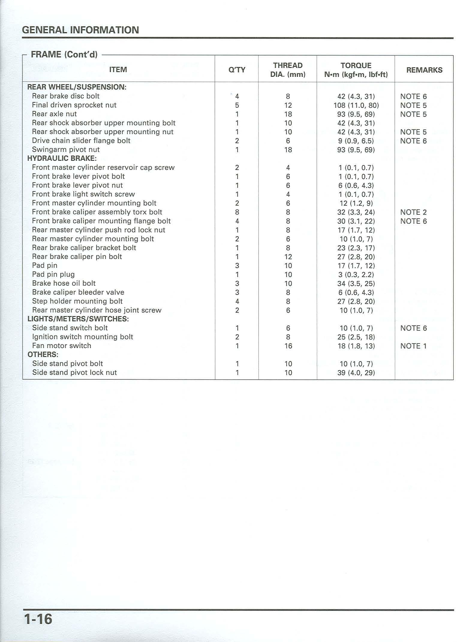
Finald riven sprocket nut 5 12 108(11 .0,80) NO TE 5
Rearaxlenut 1 18 93(9 .5, 69) NO TE5
Rearshockabsorbe r upper mounting bolt 1 10 4 2 (4. 3 , 3 1)
Rearshockabso rber upper mount ing nut 1 10 42(4 .3,31 ) NOTE 5
Drivechainsliderf lange bolt 2 6 9(0.9,6 .5) NOT E 6
Swingarmpivotnut 1 18 93(9 5 , 69)
Frontmaster cylinder reservoir capscrew 2 4 1(0 .1,0.7)
Frontbrake leverpivo t bolt 1 6 1(0 .1, 0.7)
F rontbrake lever p ivot nut 1 6 6(0 .6, 4 .3)
Frontbrakelightswitchscrew 1 4 1(0 .1, 0 .7)
Frontmaste r cyl inder mount ing bolt 2 6 12( 1.2, 9)
Frontbrake caliper assemb ly torx bolt 8 8 3 2 (3 3, 24 ) NO TE 2
Frontbrakecaliper mount ing flange bo lt 4 8 30(3 .1,22) NOT E 6
Rear master cylinder pushrodlock nut 1 8 17(1 .7 , 12 )
Rearmaster cylinder mounting bolt 2 6 10(1.0,7)
Rearbrakecal iper bracket bolt 1 8 23 (2 3,17)
Rearbrake caliper pinbolt 1 12 27(2 .8, 20)
Padpin 3 10 17(1.7, 12 )
Padpinplug 1 10 3(0 3, 2 .2)
Brakehoseoil bolt 3 10 3413 .5,25)
Brakecal iper bleeder valve 3 8 6(0 .6, 4 .3)
Stepholder mounting bolt 4 8 2 7(2.8,2 0)
Rearmastercyl inder hosejointscrew 2 6 10(1 .0, 7)
S ide standsw itch bolt 1 6 10(1.0 , 7) NO TE 6
Ignitionswitch mount ing bolt 2 8 2512.5,18)
Fanmotorswitch 1 16 1811 .8,13) NOTE 1
Sidestand pivot bolt 1 10 10(1.0 , 7) Side standp ivot locknut 1 10 39(4 .0, 29)