
Waterford Public Schools
Solidworks – 3D Modeling Curriculum
The following staff made significant contributions to the development of the Waterford Public Schools CTE Curriculum:
Michael Bono
Ed Torres
Waterford High School CTE Teacher
Waterford High School CTE Teacher


Information Analysts

1A: Listen actively to understand information.
1B: Use an appropriate method of communication.
1C: Create a logical and evidence-based argument.
1D: Deliver a clear and effective presentation or performance.
2A: Use appropriate research tools to acquire information from a variety of sources.
2B: Evaluate different perspectives, biases, and levels of credibility.
2C: Analyze information gathered from research tools to demonstrate understanding.
3A: Make reasonable predictions of a real-world issue.
3B: Analyze data in order to justify a claim.
4A: Persevere through challenging situations with flexibility and resourcefulness.
4B: Recognize how thoughts, feelings, and actions affect achievement.
4C: Work independently towards achieving a meaningful goal.
5A: Demonstrate respect for all cultures, identities, and perspectives.
5B: Practice responsible digital citizenship.

We prepare students for success through industry-aligned programs, real-world applications, and building essential skills. Through innovative curriculum, industry partnerships, and personalized pathways, we inspire students to discover their passions, develop employability skills, and achieve their full potential. Our students are trained to be adaptable professionals who make meaningful contributions and thrive in the dynamic global economy.
We build the capacity of our students to independently problem solve, create, and evaluate ideas based on the following goals:
● Demonstrate professionalism through exhibiting attentiveness, growing from feedback, and adhering to industry standards (VOG: Self-Directed Learners);
● Become fluent in the tools and techniques to achieve an expected level of precision based on industry standards (VOG: Critical Thinkers, Self-Directed Learners);
● Develop a product or possible solution that addresses the problem and adheres to key task constraints (e.g., timeline, cost, restrictions, available resources, audience) (VOG: Critical Thinkers, Information Analysts, Self-Directed Learners);
● Work together on a common goal to break down a task in manageable pieces, generate ideas, address interpersonal and technical challenges, and follow through on task responsibilities (VOG: Effective Communicators, Self-Directed Learners, Responsible Citizens);
● Communicate effectively based on audience, purpose and task using appropriate vocabulary (VOG: Effective Communicators, Self-Directed Learners, Responsible Citizens); and
● Develop a portfolio of accomplishments that highlight employability skills with related artifacts to showcase their talent and expertise (VOG: Effective Communicators, Self-Directed Learners).
We champion the transformative power of practical skills and real-world application in our instruction in every course. We leverage connections in other subject areas to showcase their relevance in the problems, products, and solutions generated in career and technical courses.
● Problem-Based Learning: We develop authentic problems for students to apply their technical knowledge to investigate, create, and communicate.
● Explicit Instruction: We teach clear, manageable, and developmentally appropriate lessons aligned to CT curriculum standards. These are followed by regular opportunities to practice and receive targeted feedback to grow over time.
● Instructional Modeling: We demonstrate possible approaches using habits of work that focus on both the problem as well as the employability skills we are committed to developing in our students.
● Coaching: We observe how students are working and ask probing questions and suggest possible areas of improvement appropriate for the goals, task, and the student.
● Peer Modeling: We create collaborative situations where students work together to design, create, and evaluate their solutions or approaches.
COURSE # WTN010 0.5 Credit (FVA,STEM)
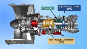
This hands-on course teaches students to create 3D parametric models using SolidWorks, focusing on key dimensions and relationships. It covers optimizing models for Computer-Aided Manufacturing (CAM) to prepare for real-world production. The course provides essential skills in both parametric design and manufacturing processes.
This course leverages the most widely used 3D CAD package in education and industry today to develop design and engineering skills students need. By taking this course students will be ready to take an industry-recognized certification exam to be credentialed as a SOLIDWORKS CAD Design associate.

Focus
Watch your initial sketch transform into a solid, parametric model with the magic of extrusion! We start the course learning the feature tools of an industryleading CAD program whose skills are in highdemand in the job market. We understand how design intent, dimensioning, and constraints affect the model's behavior and its relationship to associated drawings.
Revolved features take your 2D designs and create cylindrical 3D models. We practice with advanced 3D modeling techniques to create complex parts utilizing a variety of software commands.
Patterning takes designs to the next level with efficiency and accuracy of part construction. Next, we generate complex patterns of features and geometry to streamline design.
Building on our experience crafting individual components, let’s bring them together to create a complete digital assembly. We integrate components using various techniques for design efficiency.
Put your designs to the ultimate test! We end the course by simulating realworld conditions to see how parts perform. We analyze part performance by calculating physical properties and conducting basic stress simulations, exploring the impact of mesh density and effectively managing simulation results.
Course Name: Solid Works 3D Modeling
Unit 1 Title: Sketching and Part Modeling
Unit Overview:
Est. # of Lessons: 7-12
Watch your initial sketch transform into a solid, parametric model with the magic of extrusion! We start the course learning the feature tools of an industry-leading CAD program whose skills are in high-demand in the job market. We understand how design intent, dimensioning, and constraints affect the model's behavior and its relationship to associated drawings
● CADD.02.07: Express a design of an object as a 3D model
● CADD.02.10: Revise a design and update finished drawings appropriately
● CADD.02.13: Describe and apply the following basic geometric concepts to building 3D models: tangent and parallel concentric.
● CADD.03.04: Apply dimensioning to various objects and features
● CADD.03.05: Edit a dimension by using various editing methods
● CADD.05.09: Create and edit basic geometry
● CADD.05.12: Create and edit dimensions
● CADD.08.02: Use sketching techniques as they apply to a variety of objects
● A deep understanding of parametric modeling principles and CAD software features allows for the creation and modification of designs where geometry is driven by relationships and dimensions, ensuring that changes propagate predictably and design intent is maintained throughout the modeling process, from initial sketch to final drawing.
● Mastery of well-constrained sketching, including understanding essential elements and applying appropriate constraints, is crucial for creating robust and modifiable 3D models that accurately reflect design intent and are reliably updated across all related documents.
● Demonstrate professionalism through exhibiting attentiveness, growing from feedback, and adhering to industry standards (VOG: Self-Directed Learners)
● Become fluent in the tools and techniques to achieve an expected level of precision based on industry standards (VOG: Critical Thinkers, Self-Directed Learners)
● Communicate effectively based on audience, purpose and task using appropriate vocabulary (VOG: Effective Communicators, Self-Directed Learners, Responsible Citizens)
● Develop a portfolio of accomplishments that highlight employability skills with related artifacts to showcase their talent and expertise (VOG: Effective Communicators, Self-Directed Learners
● How do the principles of parametric modeling and the features of the platform help me to create and modify designs that effectively capture and communicate design intent?
● What are the essential elements of a wellconstrained sketch? How do I use that to create a solid model that effectively captures and communicates design intent?
● How can I effectively use sketching and feature tools to create and modify a 3D part model that effectively captures and communicates design intent?
● How do I ensure that changes to my 3D model are accurately reflected in related drawings while still maintaining design intent?
Key Vocabulary: parametric model, sketch, geometry terms (e.g, cylinder, arc, sphere, plane, 2D, 3D, dimensioning methodology, design intent, feature manager, design tree, fillets, sketch relations, bosses, hole features
● I can explain how a parametric solid model works.
● I can compare key characteristics of parametric and nonparametric models
● I can distinguish between sketched and applied features.
● I can identify the principal components of the platform user interface.
● I can explain how different dimensioning methodologies convey different design intents.
● I can create a new part.
● I can insert a new sketch.
● I can add sketch geometry.
● I can establish sketch relations between pieces of geometry.
● I can assess the state of the sketch to determine whether it is under constrained, over constrained or fully designed.
● I can extrude the sketch into a solid.
● I can determine the orientation of the sketch in the proper plane
● I can create different types of hole features.
● I can insert fillets on a solid.
● I can use the editing tools to modify the design intent
● I can make a basic drawing of a part.
● I can make a change to a dimension.
● I can demonstrate the associativity between the model and its drawings.
Summative Assessment
Experiment with different ways of modeling a part to verify its design intent
Formative Assessment
Series of practice problems that involve basic sketching and modeling
First Topic: Introduction to Platform
Learning Targets:
● I can explain how a parametric solid model works.
● I can compare key characteristics of parametric and nonparametric models
● I can distinguish between sketched and applied
Estimated # of Lessons:
Essential Question:
● How do the principles of parametric modeling and the features of the platform help me to create and modify designs that effectively capture and communicate design intent?
features.
● I can identify the principal components of the platform user interface.
● I can explain how different dimensioning methodologies convey different design intents.
Learning Activities:
● Introduction to SOLIDWORKS basics and user interface
● Design intent and how features affect design intent
● Learning how to use the command manager
Second Topic: Introduction to Sketching
Learning Targets:
● I can create a new part.
● I can insert a new sketch.
● I can add sketch geometry.
● I can establish sketch relations between pieces of geometry.
● I can assess the state of the sketch to determine whether it is underconstrained, overconstrained or fully designed.
● I can extrude the sketch into a solid.
Learning Activities:
Estimated # of Lessons:
Essential Questions:
● What are the essential elements of a wellconstrained sketch? How do I use that to create a solid model that effectively captures and communicates design intent?
● Stages in the process: create a new part, create a sketch, add sketch geometry, define sketch relationships
● Basic sketching: mechanics of sketching, inference lines, rules that govern sketching
● Creating 2D sketches that meet design intent
Third Topic: Part Modeling
Learning Targets:
● I can determine the orientation of the sketch in the proper plane
● I can create different types of hole features.
● I can insert fillets on a solid.
● I can use the editing tools to modify the design intent
● I can make a basic drawing of a part.
● I can make a change to a dimension.
● I can demonstrate the associativity between the model and its drawings.
Learning Activities:
Estimated # of Lessons:
Essential Questions:
● How can I effectively use sketching and feature tools to create and modify a 3D part model that effectively captures and communicates design intent?
● How do I ensure that changes to my 3D model are accurately reflected in related drawings while still maintaining design intent?
● Stages in basic modeling: new part, profile choice, sketch plane choice, design intent, first feature, bosses, cuts and whole features, fillets, editing tools, drawings, and dimension changes
Course Name: Solid Works 3D Modeling
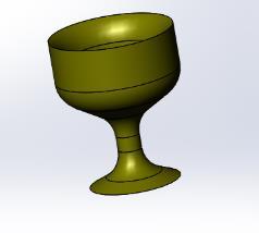
Unit 2 Title: Revolved Features
Unit Overview:
Est. # of Lessons: 3-6
Revolved features take your 2D designs and create cylindrical 3D models. We practice with advanced 3D modeling techniques to create complex parts utilizing a variety of software commands.
● CADD.02.07: Express a design of an object as a 3D model
● CADD.02.13: Describe and apply the following basic geometric concepts to building 3D models: tangent and parallel concentric
● CADD.03.04: Apply dimensioning to various objects and features
● CADD.03.05: Edit a dimension by using various editing methods
● CADD.05.09: Create and edit basic geometry
● CADD.05.12: Create and edit dimensions
● CADD.06.03: Create and edit construction planes through reference geometry
● CADD.06.04: Create and modify geometric components on construction planes
● CADD.08.02: Use sketching techniques as they apply to a variety of objects
Different 3D modeling techniques offer unique ways to create geometric forms that can build complex part models that accurately represent my design intent.
Knowledge
Key Vocabulary: multibody solid, sweep features, boss
Transfer Goals
● Demonstrate professionalism through exhibiting attentiveness, growing from feedback, and adhering to industry standards (VOG: Self-Directed Learners)
● Become fluent in the tools and techniques to achieve an expected level of precision based on industry standards (VOG: Critical Thinkers, Self-Directed Learners)
● Develop a product or possible solution that addresses the problem and adheres to key task constraints (e.g., timeline, cost, restrictions, available resources, audience) (VOG: Critical Thinkers, Information Analysts, Self-Directed Learners);
● Develop a portfolio of accomplishments that highlight employability skills with related artifacts to showcase their talent and expertise (VOG: Effective Communicators, Self-Directed Learners)
● How can I use various 3D modeling techniques to design parts for a solid model?
Skills (Framed as Learning Targets)
● I can create revolved features.
● I can apply dimensioning techniques to sketches for revolved features.
● I can use multibody solid technique to create multiple parts.
● I can create a sweep feature to incorporate into the solid model.
● I can calculate the physical properties of a part.
Create different revolved models with fully defined sketches. Add various features such as, fillets, holes etc.
● Practice problems that involve creating sketches for revolved models
● Practice problems that involve sweep geometry
First Topic: Revolved Features
Learning Targets:
● I can create revolved features.
● I can apply dimensioning techniques to sketches for revolved features.
● I can use the multibody solid technique to create multiple parts.
● I can create a sweep feature to incorporate into the solid model.
Learning Activities:
● Rules governing sketches of revolved features
● Sketching geometry of the revolved feature
Estimated # of Lessons: 3-6
Essential Question:
● How can I use various 3D modeling techniques to design parts for a solid model?
○ Stages in the process: new part, design intent, revolved features, multibody solids, and sweep features
● Sample revolved model exercises: flange, wheel, guide, ellipse, slide stop, cotter pin, paper clip, mitered sweep, simulation
Course Name: Solid Works 3D Modeling
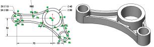
Unit 3 Title: Patterning
Unit Overview:
Est. # of Lessons: 3-6
Patterning takes designs to the next level with efficiency and accuracy of part construction. Next, we generate complex patterns of features and geometry to streamline design.
Established Goals
● CADD.02.07: Express a design of an object as a 3D model
● CADD.02.10: Revise a design and update finished drawings appropriately
● CADD.02.13: Describe and apply the following basic geometric concepts to building 3D models: tangent and parallel concentric
● CADD.03.04: Apply dimensioning to various objects and features
● CADD.03.05: Edit a dimension by using various editing methods
● CADD.05.09: Create and edit basic geometry
● CADD.05.12: Create and edit dimensions
● CADD.06.03: Create and edit construction planes through reference geometry
● CADD.06.04: Create and modify geometric components on construction planes
● CADD.08.02: Use sketching techniques as they apply to a variety of objects
● Using patterning tools allows me to efficiently create multiple instances of features, saving time and ensuring consistency across my design.
● Choosing the appropriate pattern type and settings is key to optimizing the design's form and function.
Key Vocabulary: array, vector, linear pattern, circular pattern, mirror pattern, sketch driven pattern, pattern seed, axis of revolution
Transfer Goals
● Demonstrate professionalism through exhibiting attentiveness, growing from feedback, and adhering to industry standards (VOG: Self-Directed Learners)
● Become fluent in the tools and techniques to achieve an expected level of precision based on industry standards (VOG: Critical Thinkers, Self-Directed Learners)
● Develop a product or possible solution that addresses the problem and adheres to key task constraints (e.g., timeline, cost, restrictions, available resources, audience) (VOG: Critical Thinkers, Information Analysts, Self-Directed Learners);
● Develop a portfolio of accomplishments that highlight employability skills with related artifacts to showcase their talent and expertise (VOG: Effective Communicators, Self-Directed Learners)
● How can I efficiently create and modify patterns of features to optimize design?
Skills (Framed as Learning Targets)
● I can create a linear pattern.
● I can create a circular pattern.
● I can create and use the reference geometry types axes and planes.
● I can create a mirror pattern.
● I can use the pattern seed only option with a linear pattern to prevent overlapping results when
the two directions use the same vector.
● I can add a sketch driven pattern.
● I can automate the process of fully defining a sketch.
Summative Assessment
Add linear, circular and mirrored pattern features to solid models and modify parameters.
First Topic: Patterning
Learning Targets:
● I can create a linear pattern.
● I can create a circular pattern.
Formative Assessment
● Practice problems that first identify the axis of revolution for a pattern and then create the pattern
Estimated # of Lessons: 3-6
Essential Question:
● How can I efficiently create and modify patterns of features to optimize design?
● I can create and use the reference geometry types axes and planes.
● I can create a mirror pattern.
● I can use the pattern seed only option with a linear pattern to prevent overlapping results when the two directions use the same vector.
● I can add a sketch driven pattern.
● I can automate the process of fully defining a sketch.
Learning Activities:
● Sample exercises to to create a pattern
○ Circular pattern - identify axes
○ Linear pattern - plane to define linear direction
○ Mirror pattern - define the line of symmetry or geometric plane
○ Sketch driven pattern - identify points
○ Pattern seed only
Unit Overview:
Est. # of Lessons: 5-8
Building on our experience crafting individual components, let’s bring them together to create a complete digital assembly. We integrate components using various techniques for design efficiency.
● CADD.02.07: Express a design of an object as a 3D model
● CADD.02.10: Revise a design and update finished drawings appropriately
● CADD.02.13: Describe and apply the following basic geometric concepts to building 3D models: tangent and parallel concentric
● CADD.05.09: Create and edit basic geometry
● CADD.06.04: Create and modify geometric components on construction planes
● CADD.07.01: Create an assembly in 3D geometry
● Demonstrate professionalism through exhibiting attentiveness, growing from feedback, and adhering to industry standards (VOG: Self-Directed Learners)
● Become fluent in the tools and techniques to achieve an expected level of precision based on industry standards (VOG: Critical Thinkers, Self-Directed Learners)
● Develop a product or possible solution that addresses the problem and adheres to key task constraints (e.g., timeline, cost, restrictions, available resources, audience) (VOG: Critical Thinkers, Information Analysts, Self-Directed Learners);
● Develop a portfolio of accomplishments that highlight employability skills with related artifacts to showcase their talent and expertise (VOG: Effective Communicators, Self-Directed Learners)
● Effective assembly design requires selecting the appropriate mating conditions and assembly techniques to accurately represent the intended relationships between components and clearly communicate the overall product function.
● Modifying assembly features, such as constraints, patterns, and sub-assemblies, is essential for managing complex assemblies and efficiently implementing design changes while preserving the integrity of the overall design.
Key Vocabulary: mating, design tree
● How can I assemble components using various techniques and mating conditions that effectively captures and communicates design intent?
● How can I modify assembly features to manage intricate assemblies and efficiently make design changes?
● I can create a new assembly.
● I can insert components into an assembly using all available techniques.
● I can add mating relationships between
components.
● I can utilize the assembly-specific aspects of the design tree to manipulate and manage the assembly.
● I can use part configurations in an assembly.
Summative Assessment
Use Assembly Motion to animate the motion of a car jack assembly to simulate physical behavior of the car jack and determine the torque required to lift a vehicle.
Formative Assessment
Practice problems that involve making an assembly from detailed parts and define mating condition of the parts
First Topic: Assembly Modeling
Learning Targets:
● I can create a new assembly.
● I can insert components into an assembly using all available techniques.
● I can add mating relationships between components.
● I can utilize the assembly-specific aspects of the design tree to manipulate and manage the assembly.
● I can use part configurations in an assembly.
Learning Activities:
Estimated # of Lessons: 5-8
Essential Questions:
● How can I assemble components using various techniques and mating conditions that effectively captures and communicates design intent?
● How can I modify assembly features to manage intricate assemblies and efficiently make design changes?
● Stages in the assembly process: creating a new assembly, adding first component, position of the first component, mating components to each other, using part configurations in assemblies, inserting subassemblies
● Sample assembly exercises: mates, gripe grinder, hide and show component, part configurations in an assembly, U-Joint changes
Unit Overview:
Est. # of Lessons: 5-8
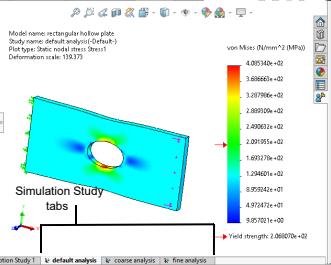
Put your designs to the ultimate test! We end the course by simulating real-world conditions to see how parts perform. We analyze part performance by calculating physical properties and conducting basic stress simulations, exploring the impact of mesh density and effectively managing simulation results.
● ENG.04.03 Test materials for specific characteristics.
● ENG.07.04 Describe and demonstrate the process for using CAD in a design solution.
● Simulation tools allow me to predict how a part will respond to applied loads, revealing areas of high stress and potential failure. The accuracy of these predictions is directly influenced by the mesh density, with finer meshes generally providing more accurate but computationally expensive results.
● Linear static stress analysis is a powerful tool that helps engineers make informed decisions about their designs, leading to safer, more efficient, and more reliable products.
● Demonstrate professionalism through exhibiting attentiveness, growing from feedback, and adhering to industry standards (VOG: Self-Directed Learners);
● Become fluent in the tools and techniques to achieve an expected level of precision based on industry standards (VOG: Critical Thinkers, Self-Directed Learners)
● Develop a product or possible solution that addresses the problem and adheres to key task constraints (e.g., timeline, cost, restrictions, available resources, audience) (VOG: Critical Thinkers, Information Analysts, Self-Directed Learners);
● Develop a portfolio of accomplishments that highlight employability skills with related artifacts to showcase their talent and expertise (VOG: Effective Communicators, Self-Directed Learners)
● How can I use simulation tools to analyze the structural behavior of a part under load? How does mesh density affect the accuracy of those results?
● What are the key steps involved in setting up and running a basic linear static stress analysis, and how can I interpret and manage the resulting data?
Key Vocabulary: mesh density, linear static study, stress, strain (displacement), finite element analysis (FEA), force, torque, pressure
● I can calculate the physical properties of a part.
● I can perform rudimentary, first pass stress analysis.
● I can navigate the simulation user interface.
● I can analyze a linear static study using solid elements.
● I can experiment with changing mesh density to compare stress results.
● I can manage simulation result files.
Summative Assessment
Use simulation to mesh a model, apply material properties, run an analysis and analyze results and compare stresses to yield and ultimate stress of material
Formative Assessment
Practice problems that create a study, apply material, apply fixtures, apply external forces, mesh the model
First Topic: Analysis Estimated # of Lessons: 5-8
Learning Targets:
● I can calculate the physical properties of a part.
● I can perform rudimentary, first pass stress analysis.
● I can navigate the simulation user interface.
● I can analyze a linear static study using solid elements.
● I can experiment with changing mesh density to compare stress results.
● I can manage simulation result files.
Learning Activities:
Essential Questions:
● How can I use simulation tools to analyze the structural behavior of a part under load? How does mesh density affect the accuracy of those results?
● What are the key steps involved in setting up and running a basic linear static stress analysis, and how can I interpret and manage the resulting data?
● Stages in the analysis process: create a study, apply material, apply fixtures, apply loads, mesh the model, run the study, analyze the results
● Sample studies that could be the basis of analysis: bracket, compressive spring stiffness, container handle