Functional Options
Chapter - F
Chapter F Table of Contents Section #
Section Name / Contents
F.1
Page # F.1.2
Hinge Boring ◦ 35mm Hinge Bore
F.1.2
◦ Demountable Hinge Slot
F.1.6
◦ Knife Hinge Slot / Dado Blade Slot
F.1.6
◦ Hinge Rout for SOSS Hinge #204 - HSR
F.1.8
◦ Standard Hinge Bore, Rout and Slot Placement
F.1.9
F.2
Miscellaneous Joinery (MJ)
F.2.1
F.3
Joint Assembly Method (JAM)
F.3.1
F.4
Half Lap Options
F.4.1
F.5
Additional Outside Edge
F.5.1
F.6
Lazy Susan Corner Door Joints
F.6.1
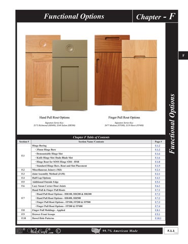
Hand Pull & Finger Pull Routs
F.7.1
F.7
◦ Hand Pull Rout Options - HR100, HR200 & HR300
F.7.2
◦ Hand Pull Rout Options - HR400, HR500
F.7.2
◦ Finger Pull Rout Options - FP100, FP200 & FP500
F.7.3
◦ Finger Pull Rout Options - FP300 & FP400
F.7.4
F.8
Finger Pull Moldings - Applied
F.8.1
F.9
Drawer Front Scoops
F.9.1
F.10
Dowel Hole Patterns
F.10.1
®
®
.com
C
99.7% American Made
Functional Options
F
F.1.1
V18.2