
Vinay Agarwal

Selected Works 2016 - 2022
Architecture Portfolio
PERSONAL SKILLS
VINAY AGARWAL Architectural Designer
Nationality: Indian
Ahmedabad, Gujarat Internship 2020
Pradeeep Sachdeva and Design Associates New Delhi Junior2021Architect
Ph: 7976742437
EDUCATION
English Fluent Hindi Native Spanish Basic
DocumentedEXPERIENCEJAIGARHFORT , Jaipur
36 Karkhanas Workshop , Jaipur
AD: Murlipura, Jaipur, Rajasthan
Email: vinayagarwalforwork@gmail.com
Aayojan School of Architecture, Jaipur, Rajasthan B.Arch, 2021
DOB: 8th Feb, 1997
LANGUAGES
RevitIndesignIllustratorPhotoshopLumionSketchupAutocadSOFTWARES Microsoft Office
Central Academy Sr. Sec Shool, Jaipur, Rajasthan 2016
Kumar Moorthy and Associates New Delhi Junior2022Architect

HirenEMPLOYMENTPatelArchitects
SketchingPaintingPhotographerFastEnthusiastDedicatedlearner
Personal MiscelleneousProfessionalWorksWorks Photography Working Drawings
Landscape Design for Bunglow Udaipur ElevationResortworkout for Bunglow Interior design Visualisation


8th Semester Design
Contents
Internship Works
Bhopal
Amila Hills Resort Shimla

Bunglow design, Alwar Kedar Farm, KerwaJaipurLakehouse
Animation & Vfx Centre
10th Semester Design project
Community Aquatic Centre
6
7
Location: HITEC City, Hyderabad, Andhra Pradesh
INTRODUCTION
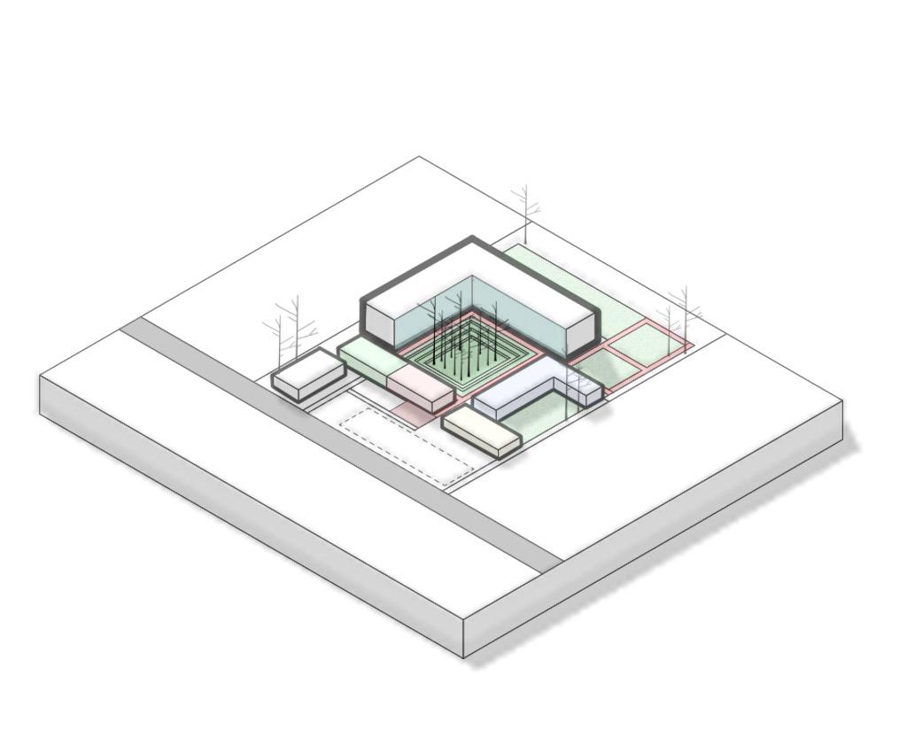
An animation and vfx centre is a Studio spaceforAnimationartists,Sketchingartists,renderingartists and more and animation is a technique in which figures modelled on softwares are manipulated to give an illusion of movement. In traditional methods of animation transparent sheets were used to draw upon and photographed and then were exhibited as film but now CGI (computer generated imagery) is being used all over with the advancement in technology. The Project has been proposed in HITEC City Hyderabad on a proposedlandof167x238m for the same project also the locality of HITEC city has also been developing as an IT sector over the last 5 years. The need of the project was like most of the corporate offices animation studios has also been deprived of the connection with the outer environment, these studios have also been facing availability of ample natural light in the studios moreover the studios has also been functioning as regular offices with partitions in the interior of offices depriving its employees of the regular brainstorming and communication or the flexibility which is most important aspect in studios which require more of creativity to bring out their best work. The aim of the project is to provide a stand alone office headquarters for all the employees working in different fields leading to one single product “Animation” also to provide a health oriented working environment for the employees. The challenges included managing the huge scale of the site in terms of zoning, visual comfort, pathways apart from this one of the major challenges was to control the harsh sun while keeping the employees connected with the outer environment and still keeping the privacy of the campus intact became a challenge too. Challenge of the huge scale of the site was dealt by opening the site slowly into compartments to the user other than that orientation of the building blocks was planned in accordance with the sun path moreover floor to ceiling height windows has been provided in the main office block facing north taking the diffused natural light in the office spaces and the building is also facing the central green courtyard of the site which is the core space for the project.
Site Area: 3.98 hectares
Animation and Vfx Centre

Scale of the blocks in the shaded areas has been cut down and the tallest block has been alloted to the studio (office) space for the animators and other artists.


2. Central Court
SITE DEVELOPMENT CONCEPT
A central court has been cut to improve the ventilation and increasing the intake of natural light into the spacces.
8
Campus has been proposed on the left side of the site (east) so as to utilise the shaded areas for rec reational activities and welcoming natural diffused light into the built blocks.
3. Scale of the Blocks
30mwideroad
1. Campus Placement
Different blocks has been placed at different locations on the site according to the feasibility of the users for example admin and auditorium areas has been proposed at the starting of the site and studio spaces has been kept apart overlooking the central court so as to keep the privacy of the employees intact.


9
6. Recreational Court
5. Cycling Track
4. Placement of the Blocks


Central shaded court has been developed as the recreational area with dense tall trees plantation to keep the employees closely connected with the nature and also to promote outdoor working environment for the creators.
A cycling track has been proposed on the site in order to minimize the tiredness among the users and also keeping in mind the health ben efits of the employees since they spend most of the time sitting in one posture in front of the screen for hours.
10 Blocks 1. Studio Block 2. Sports and Recreational Block 3. Cafeteria 4. Admin & Auditorium 5. Parking ROOF PLAN

1. Entry with water feature 2. Driveway and walkway 3. Main pathway 4. Pre court 5. Central court

APPROACH ON SITE
Zones

Site Movement
11
Movement on the site has been kept indirect to break down the huge scale of the site and to avoid any visual tiredness for the users coming onto the site. Hence the site opens up into different compartments of increasing scale for the user.
SITE PLAN B’ A

13 A’B


14 SectionSection


15 Section AA’ Section BB’


STUDIO BLOCK PLACEMENT
Disconnected sketching artists and Animation artists floors.
Utilising the shaded areas in the court adjacent to studios for outdoor working and recreational purpose.
Scooping out a court and proposing the full floor to ceiling windows on the shaded side of the building to welcome the natural northern diffused light into the office spaces


STUDIO BLOCK CONCEPT
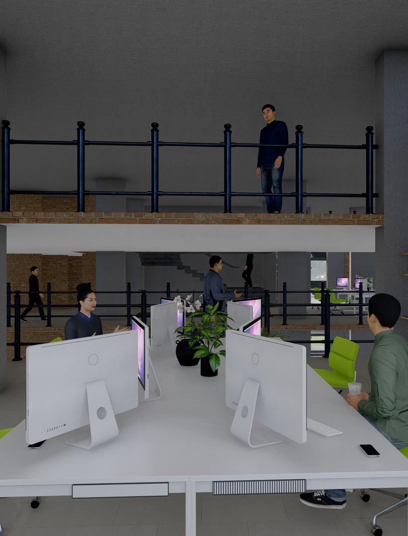
Cutout on the first floo to increase the connection between the artists (keeping in mind the hand in hand working style of the studios).
Maximising the working output by keeping more employees connected to each other and achieving the diversity in the unit.
16
VERTCAL CONNECTION
Studio block placed on the site

Employees interacting space

Studio Block opening towards Central court
Cantilevered Working /Recreational Area
Since all the employees of the office be it sketching artists, Animation artists, Rendering artists would be working on the computer systems for any project the Studio Block has been mechanically ventilated to protect systems from any harm. These cantilevered spaces which are open to sky are provided for the users to keep them naturally connected with the outer environment too, these spaces can be utilised for working and recreational purpose both by the employees.

17
CantileveredOpenBlockstosky
18


19 Section AA’
Second, Fifth, Eighth Floor

Studio Block
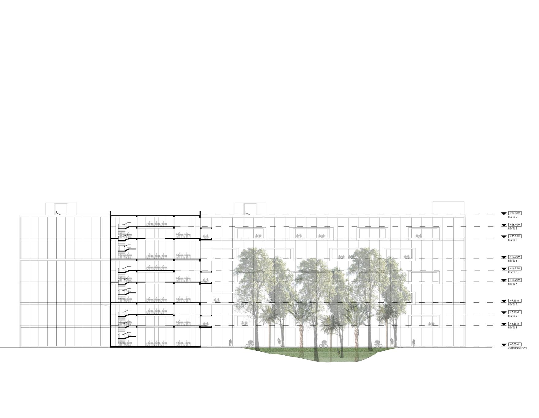
Shading Element
Since the longitudnal side of the Sports and Recreational Block is facing South-east direction letting in the sun into the Yoga and Gymnesium shading elements have been proposed by extending the wall to a limit where it allows only diffused light into the spaces. Apart from that all the spaces below the extended areas has been developed as the seating and outdoor working areas for the employees.


21 Ground Floor First SectionFloorBB’ Sports and Recreational Block

22

23

Site Area: 7.3 Hectares
24
Amila Hills
Location: Shimla, Himachal Pradesh

25

26LEVEL (-1) Guest Block
27(-1) PLAN
28 455 2500 Guest Block
29 View 1 View 2


30 Entrance Block
31 View 1 View 2


32
Community Aquatic Centre
Site Area: 8200sqm

INTRODUCTION
33
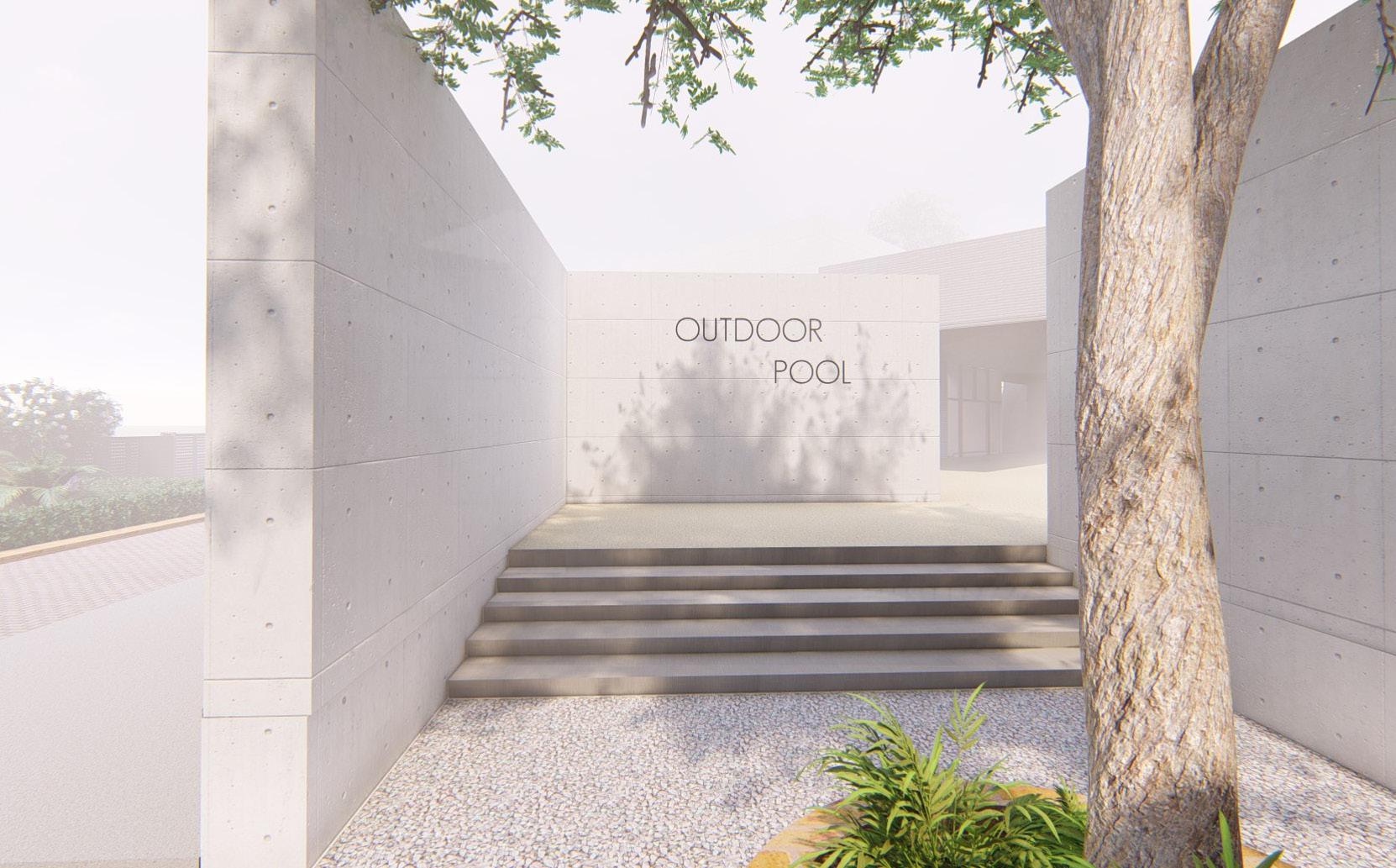
Aquatics are an important part of recreation nationwide. Aaquatics often lead the list of desired public recreational amenities in the city level park plans. Additionaly, a strong aquatics program is vitally important for all the children and adults to learn to swim especially in a community. The main aim of the project was to provide a centralised centre for the local community in terms of recreational space where the project is more inclined towards aquatics sports and facilitates spaces like instruction pool, therapy pool, toddlers pool, Party centre, Outdoor pool, Aerobics hall, Fitness area, Sauna platform and a Restaurant. With the increasing development and the availability of land in the sitapura area of Jaipur the site has been proposed there with an area of 110 x 75sqm. While designing the centre the movement of the users on the site and keeping the different zones of the centre apart yet giving the users flexibility to move around the centre fluently became one of the major challenges, which was dealt by keeping the planning more open on the site.
Location: Sitapura, Jaipur, Rajasthan
1. Site
3. Outdoor pool
First outdoor pool and toddlers pool has been proposed centrally on the site which becomes the primary pool and would be used most by the users.
34
2. Initial Blocks

A corner site of 110 x 74m proposed for the aquatic centre .
At first parking is proposed on one end of the site and blocks which would be used first just after parking has been placed on the site .

SITE DEVELOPMENT CONCEPT

5. Fitness Area
35
6.area.
Instruction pool area acquired the biggest site area and has been placed on one corner of the site and is connected with the outdor pool simultaneously.

Evaporative Cooling
4. Instruction pool Blok
With the flow of the wind in the same direction the outdoor pool facilitates the evaporative cooling effect in Fitness area and Cafeteria court at the same time.

Fitness area including aerobics has been placed on top of admin area which not only overlooks the outdoor pool but also instruction pool area from inside. And also a courtyard is cut in the cafeteria

Photo: View of instrcution pool ith circular skylights.
36

Fitness area has been placed in such a manner that it is connected with the outdoor pool and instruction pool at the same time.
37
Connection of Fitness Area


(2.50X5.00) PARKINGCAR
(2.50X5.00) PARKINGCAR
38 (2.50X5.00)PARKINGCAR (2.50X5.00)PARKINGCAR (2.50X5.00)PARKINGCAR (2.50X5.00)PARKINGCAR (2.50X5.00)PARKINGCAR (2.50X5.00)PARKINGCAR (2.50X5.00) PARKINGCAR (2.50X5.00) PARKINGCAR (2.50X5.00) PARKINGCAR (2.50X5.00) PARKINGCAR (2.50X5.00) PARKINGCAR (2.50X5.00) PARKINGCAR (2.50X5.00) PARKINGCAR
ROAD9MWIDE (2.50X5.00)PARKINGCAR
B’ A B A’ Ground Plan
DRIVEWAY
PARKINGCAR UTENSILS STORE GREEN TOILETS(M)(M)CHANGE&SHOWERSTORE TOILETS(F) BUFFET KITCHEN STORAGE GREEN GREEN UP UP (M)CHANGE&SHOWER (F)CHANGE&SHOWER ADMIN OFFICE ADMIN OFFICE CHILDCARE UP RECEPTIONAND WAITING RESIDENTIAL ROAD9MWIDE ROAD12MWIDE
(2.50X5.00)
MECHANICSPOOL
DECK CHANGE &SHOWER(F) INDOORSWIMMINGPOOL OUTDOORSWIMMING POOL PARKING CAFETERIA KITCHEN PARTYHALL GREEN GREEN GREEN GREEN GREEN DRIVEWAY DRIVEWAY ENTRY ENTRYTOCAFE ENTRYTOCAFE TOENTRYINS.POOL ENTRYTOOUTDOORPOOL TOENTRYPARTYHALL ENTRY1 ENTRY2 GUARDROOM UP UPUP UP TODDLER'S POOL
(2.50X5.00)PARKINGCAR
39 UP LOCKER& CHANGING RECEPTIONLOCKER& CHANGING AEROBICSANDGYM SAUNASAUNA THERAPYPOOL N B’ A B A’ First Plan

40
Photo: Entrance courtyard towards instruction pool and outdoor pool.

Back Elevation
+0.00 SWIMMINGLEVELPOOL+0.75+4.75section AA’ section BB’’
41
Front Elevation
42

43

Area: Project52,800sqft.Area:14,400sqft.
has been done in a way that the rooms are overlooking into the central court which becomes a secure space for kids to play since the the size of the land is big at the same time living room, kitchen and swiiming pool areas are overlooking into the vast horizon of the farm land. The project has been designed keeping in mind the vastu constrains at an extend.

KERWA LAKE FARM HOUSE
44
Location: Kerwa, Bhopal, Madhya Pradesh
The Client lives in a joint family comprising of five families along with the Grandparents and wanted a getaway farm house place in the outskirts of the city. Since the client has a joint family initial brief suggested a seperate room for each family along with some extra guest rooms all with the attached restrooms, Kitchen space, Living area and a Swimming Thepool.planning
45


46
LEGEND
DRG.NO. 4. FOR
IN D/W. WHERE
& VENTILATORS LEGEND
SUNK
SLABS SHOWN IN DRAWING THICK WITH 4" THICKNESS SHOWN FOR PACKING & FINISH, (7" IN CASE OF TERRACE / ROOF). IN CASE STRUCTURAL DRAWINGS DEPICTING SLABS REQUISITE CEILING HEIGHT OF SLAB LEVEL MINIMUM REDUCE CLADDING THICKNESS APPLICABLE ALL NOTES & REFER ALL DOORS/WINDOWS REFER
1. ALL DIMENSIONS ARE IN FEET & INCHES.
NOTES:7.ALL8"BEAM
ROOM BELOW WHILE MAINTAINING TOP OF
AT EVEN
4. ALL LEVELS ARE FINISHED FLOOR LEVELS.
REDUCTION TO BE
DRG. NO. A-03 FILE:EDIT BY: N W S E KUMAR MOORTHY & ASSOCIATES Architects and Interior Designers C-9 / 9250, VASANT KUNJ, NEW TEL: ARCHITECTemail:office@kumarmoorthy.com,40044887,40044888,41767501websitewww.kumarmoorthy.com: BHOPALBHOPAL\PRESENTATION\KERWAC:\USERS\ACHINT\DESKTOP\VINAYAUTOCAD\KERWA,DRAWINGS(21STMARCH2022)\CAD
THICKNESS
8. INDICATES MAIN REFERENCE GRID START OUT FROM THIS GRID * ALL CENTER - LINE DIMENSIONS ARE THESE GRIDS
/ WALLS CENTERED ON GRID EXCEPT WHERE DEPICTED.
THAN 5"
5. REFER STRUCTURAL CONSULTANT'S DRAWINGS ALL RCC, FOUNDATION & OTHER STRUCTURAL DETAILS,IN CASE OF ANY DISCRE PANCIES ARCHITECTURAL & STRUCTURAL DRAWINGS SAME TO THE ARCHITECT PRIOR TO EXECUTION.
3. ARROWS ON STAIRS INDICATE UPWARD 2. DRAWINGS TO BE READ,DO NOT MEASURE.
NOTES:-1.ALLR.C.C.FLOOR
FOR FLOOR PACKING 2.
47 LOWERWORKINGFLOORLIVING DRG. NO A-03 TITLE S.N.PROJECTREVISION DRAWN CLIENT MR. YOGENDRA SINGH R1.R2.SHEET NO. 3 OF 8 SCALE: CHECKEDNTSBY: M.K DATE: 31-03-2022 KERWA LAKE, BHOPAL YOGENDRA SINGHRESIDENCELEGEND:G G A.C. 1. INDICATES VERTICAL HORIZONTAL CEILING LVL. ALSO REFER ELECTRICAL & SANITARY 2. INDICATES EXHAUST FAN IN MASONRY WINDOW FANLIGHT REFER SECTION & ELECTRICAL 3."A.C." INDICATES WINDOW AIR CONDITIONER MASONRY OPENING SILL AT AS/DRG. & LINTEL OR IN WINDOW AS/ DETAIL. ALSO REFER ELECTRICAL 4. INDICATES SPLIT AIR CONDITIONER AT CEILING LVL. ALSO REFER ELEC. & SANITARY LAYOUT.PROVIDE DRAIN IN 3/4" PVC / G.I. PIPE EXTERIOR SPACE/NAHANI TRAP AS / INSTRUCTIONS. 5. "W.M."/ DR INDICATE WASHING MACHINE / DRYER. ALSO REFER ELEC.& SANITARY LAYOUT. 6. THIS INDICATE LEVEL DROP INTERIOR TO INTERIOR = 21 INTERIOR TO EXTERIOR = 1" 7. INDICATES CASSETE AIR CONDITIONER AT CEILING MOUNTED ALSO REFER ELEC. LAYOUT.PROVIDE DRAIN IN 3/4" PVC/G.I.PIPE NEAREST EXTERIOR SPACE/NAHANI TRAP AS
9. INDICATES OTHER SUBSIDIARY GRIDS.
5"
8. AC FURRED IN UNITS CONCEALED CEILINGS INCLUDING VENT DIRECTION AHU CUT-OUT AREA AREA10.9.
6. STAIRCASEWIDTHS:AS / PLAN TREADS : AS PLAN RISERS : EQUAL, FLR. TO FLR. AS / DRG.
3. FOR
48
3. ARROWS ON STAIRS INDICATE UPWARD DRAWINGS TO BE READ,DO NOT MEASURE.
8. INDICATES MAIN REFERENCE GRID OUT FROM THIS GRID CENTER - LINE DIMENSIONS ARE THESE GRIDS
REDUCTION TO BE CEILING HEIGHT OF ROOM BELOW WHILE MAINTAINING TOP OF SLAB AT EVEN LEVEL THICKNESS MINIMUM FOR FLOOR PACKING 2. REDUCE CLADDING THICKNESS IN D/W. WHERE APPLICABLE 3. FOR ALL NOTES & LEGEND REFER DRG.NO. 4. FOR ALL DOORS/WINDOWS & VENTILATORS LEGEND REFER DRG. NO. A-03 FILE: N W S E EDIT BY: KUMAR MOORTHY & ASSOCIATES Architects and Interior Designers C-9 / 9250, VASANT KUNJ, NEW TEL: ARCHITECTemail:office@kumarmoorthy.com,40044887,40044888,41767501websitewww.kumarmoorthy.com: BHOPALBHOPAL\PRESENTATION\KERWAC:\USERS\ACHINT\DESKTOP\VINAYAUTOCAD\KERWA,DRAWINGS(21STMARCH2022)\CAD SECTIONSECTION
IN
9. INDICATES OTHER SUBSIDIARY GRIDS.
6. STAIRCASEWIDTHS:AS / PLAN TREADS : AS / PLAN RISERS : EQUAL, FLR. TO FLR. AS / DRG.
4. ALL LEVELS ARE FINISHED FLOOR LEVELS.
7. INDICATES CASSETE AIR CONDITIONER AT CEILING MOUNTED ALSO REFER ELEC. LAYOUT.PROVIDE DRAIN IN 3/4" PVC/G.I.PIPE NEAREST EXTERIOR SPACE/NAHANI TRAP AS AC FURRED IN UNITS CONCEALED CEILINGS INCLUDING VENT DIRECTION AHU AREA
5. REFER STRUCTURAL CONSULTANT'S DRAWINGS ALL RCC, FOUNDATION & OTHER STRUCTURAL DETAILS,IN CASE OF ANY DISCRE PANCIES ARCHITECTURAL & STRUCTURAL DRAWINGS SAME TO THE ARCHITECT PRIOR TO EXECUTION.
1. ALL DIMENSIONS ARE IN FEET & INCHES.
8.
5. "W.M."/ DR INDICATE WASHING MACHINE / DRYER. ALSO REFER ELEC.& SANITARY LAYOUT.
49 DRG. NO B-01 TITLE S.N.PROJECTREVISION DRAWN CLIENT MR. YOGENDRA SINGH R1.R2.SHEET NO. 6 OF 8 SCALE: CHECKEDNTSBY: M.K DATE: 31-03-2022 KERWA LAKE, BHOPAL YOGENDRA SINGHRESIDENCELEGEND:G G CASSETE 1. INDICATES VERTICAL / HORIZONTAL CEILING LVL. ALSO REFER ELECTRICAL & SANITARY 2. INDICATES EXHAUST FAN IN MASONRY WINDOW FANLIGHT REFER SECTION & ELECTRICAL 3."A.C." INDICATES WINDOW AIR CONDITIONER MASONRY OPENING SILL AT AS/DRG. & LINTEL OR IN WINDOW AS/ DETAIL. ALSO REFER ELECTRICAL 4. INDICATES SPLIT AIR CONDITIONER AT CEILING LVL. ALSO REFER ELEC. & SANITARY LAYOUT.PROVIDE DRAIN IN 3/4" PVC / G.I. PIPE EXTERIOR SPACE/NAHANI TRAP AS / INSTRUCTIONS.
SUNK AREA10.9.
6. THIS INDICATE LEVEL DROP INTERIOR TO INTERIOR = 21 INTERIOR TO EXTERIOR = 1"
2.
IN DRAWING 5"
/ WALLS CENTERED ON GRID EXCEPT WHERE DEPICTED.
NOTES:-1.ALLR.C.C.FLOOR
SLABS SHOWN THICK WITH 4" THICKNESS SHOWN FOR PACKING & FINISH, (6" IN CASE OF TERRACE / ROOF). CASE STRUCTURAL DRAWINGS DEPICTING SLABS THAN 5" REQUISITE
* ALL
CUT-OUT
NOTES:7.ALL8"BEAM
50

51

Task:
Designing of Clubhouse and landscaping around the site. Plan
52 CENTER ENTRANCE FOYER 4985 3960 FORMAL LIVINGCOURTYARD 6260 5255 9600 7095 STORE CLOTHESDRYING OUTDOOR DECK 7390 8215UP 2735 2440 BEDROOM AND LOUNGE 7315 12195 COURT YARD DRESS 3910 x 2235 COURT COURT 9985 3220 COURTYARD LIFT COURT YARD COURT YARD W.C 1675SHOWER21601675 2160 BASIN AREA 3055 2390 Un.Fin.Fl.lvl. +1800 Un.Fin.Fl.lvl. +1800 Un.Fin.Fl.lvl. +1800 Un.Fin.Fl.lvl. +1800 Un.Fin.Fl.lvl. +1800 Un.Fin.Fl.lvl. +1350 Un.Fin.Fl.lvl. +6'0" Un.Fin.Fl.lvl. +4'6" PLANTATION PLANTATION PEBBLES GATE [1'-1[1'-1 GUARD POOLSWIMMING GYMMASSAGESPATHEATRE PASSAGE PANTRYWASHROOMBAR DECKWASHROOMWASHROOM PLANTATION SPORTS PLANTATION PLANTATION PLANTATION PLANTATION PLAZAPARKINGSCULPTUREPARKING ENTRANCEDRIVEWAY PARKING COURTYARD CARTWAYFRUITGARDEN SEATINGAREA GAZEBO PARKINGGOLF DECK FORPERPERTREESZODIACASZODIAC BAR JACUZZI PLANTATIONPLANTATION WAY PEBBLESLAWN DEEPAK MEWADA BUNGLOW (Club/Landscaping Design)
Yoga
Gymnesium
Water body through pool

53 GazeboSwimmingClubhousepoolParkingareawithlilypond


Sitout area Area

View from Main road
54 UDAIPUR RESORT (Elevation Design)


View 4
View 2


View 3
55
56
View

57 View 5

58 =12"TREAD 6.25"=RISER D1 D2 D3 D4 D4 D4 W1 W3 W2 W4 W4 W6W5W5 W7 W8 W9 V1 V1 =12"TREAD 6.25"=RISER D3 D4 D1 D2 W1 D4 W2 D4 W3 W4 W4 W6W5W5 W7 W8 W9 V1 V1 +2'0"lvl +5'0"lvl +0'0"lvl +5'0"lvl +2'0"lvl -0'6"lvl +2'6"lvl Driveway Entry CabinSecurityGeneratorroom Planter PlanterPlanterPlanter Driveway Entry Planter Walkway+4'0"lvlLawn +5'0"lvlDeck +5'0"lvlDeck gateSliding Planter ServantServant1quarterquarter2 PantryPantryServantToilet 1quarter Servant PantryPantryquarterToilet PlanterSculptureSculpture slope slope slope slopeLawnLawn Planter GazeboWaterfountainWaterfountainareaUtilityUtilityarea Planter PlanterPlanter Planter Planter +4'6"lvl Planter Planter +4'6"lvl +3'0"lvl+3'6"lvl+4'0"lvl+2'6"lvl+2'6"lvl 14' 4'-4 105'-4" 4'-4 10' 29'-6" 15'-9" 25'-3" GateWicket structureperascolumnM.S structureperwallRetaining detailperasGazebo perasCabinSecurity detail detailperasGateCompoundwallasper detail peraswallCompound detail asstructureParking detailper 25'-3" 15'-9" 29'-6" 13'-11" perasfountainWater detail structurepercolumnM.S Planter 9'-6" 4'-5" 9" 28' perascabinSecurity detail perascabinSecurity detail +4'6"lvl 4'-7 4'-7 detailperasKerbing detailperasKerbingKerbingasperdetaildetailperasPlantation 4'-7 4'-7 2'-6 10'-1 9'-8 4' 12' 3' Toilet 31' 18' 18'-6" 43'-5" detailperasKerbing asstructureParking detailper 23.962° 23.962° 9" 23.962° 6'-1 23.962° +2'6"lvlParkingCarPlanter12'-6" +2'6"lvlParkingCarPlanter Foyer +2'0"lvl structureperascolumnM.S +3'0"lvl+2'6"lvl gateSliding GateWicket+2'0"lvldetailperasGate 4' detailGateMetalwallcompoundPlasteredMetalcolumnperstructure ENTRANCE +0'-0"LVLDRIVEWAY +2'-0"LVLPLINTH +5'-0"LVLLINTELFLOORFIRST detailperasstructureParking WALLCOMPOUND +8'-6"LVL detailperstructureParking TOPSLABSECURITYwindowLight+11'-6"CabinSecurityGeneratorroom structureperascolumnM.SstructureperascolumnM.S +2'6"lvl+2'6"lvl 5' wallcompoundPlasteredwindowLightSky detailperGateMetalMetalcolumnasperstructure +3'0"lvl +2'0"lvl PLINTHCABINSECURITY +3'-0"LVLLAWN AELEVATION C'C A A' B B' MILAN DESAI (Bunglow Landscaping project) Site Plan
SECURITY
DRIVEWAYENTRANCELVL+0'-0"LVL+2'-0"PLINTHLVL+5'-0"LINTELLVL+12'-9"FIRSTFLOORLVL+17'-6"COMPOUNDWALLLVL+8'-6"
59 Foyer LVL +2'-0"6" LVL +5'-0" DrivewayLVL +2'-6"6" LVL +3'-0"6" LVL +3'-6"6" LVL +4'-0"6" LVL +4'-6"6" LVL +5'-0" Flooring as per selection PCCMortaras per structure Dry rubber soiling LVL Planter+0'-6" 6'-6" Compound wall LVL Planter+0'-6" LVL Walkway+2'-6" LVL Planter+2'-0"
3'-6" 3' 4'-9" 8'-6" SECURITY SLAB TOP LVL +11'-6" 1'-3" 6' 3' 1' 7' 6" 7' 6" 8' 6" 1' 9' 1' LVL Planter+2'-0"RCC slab Door as per vendor LVL Driveway+2'-0" LVL Security+3'-0" Cabin LVL Generator+3'-0" room Sky light window as per vendorWindow as per vendor
1'
1'
DRIVEWAYENTRANCELVL+0'-0"LVL+2'-0"PLINTHLVL+5'-0"LINTELLVL+12'-9"FIRSTFLOORLVL+17'-6"COMPOUNDWALLLVL+8'-6"1' 3'
DRIVEWAYENTRANCELVL+0'-0"LVL+2'-0"PLINTHLVL+5'-0"LINTELLVL+12'-9"FIRSTFLOORLVL+17'-6"COMPOUNDWALLLVL+8'-6"1' 3' 3'-6" 3' 4'-9" 8'-6" SLAB TOP LVL
1' 1' 3' 3'-6" 3' 4'-9" 8'-6" SECURITY SLAB TOP LVL +11'-6" 1'-3" 6' 3' DRIVEWAYENTRANCELVL+0'-0"LVL+2'-0"PLINTHLVL+5'-0"LINTELLVL+12'-9"FIRSTFLOORLVL+17'-6"COMPOUNDWALLLVL+8'-6"1' 1' 2' 3'-6" 3' 4'-9" 5'-6" SECURITY SLAB TOP LVL +11'-6" 1'-3" 6' 3' 1' SECURITY CABIN PLINTH LVL +3'-0" 3' SECURITY CABIN PLINTH LVL +3'-0" SECURITY CABIN PLINTH LVL LAWN+3'-0" LVL +4'-0" LAWN LVL +4'-0" LAWN LVL +4'-0" LVL Lawn+4'-0" Retaining wall Flooring as per selection PCCMortaras per structure Dry rubber soiling Sweet earth Door as per vendor 7' 1' Window as per vendor LVL Security+3'-0" Cabin Flooring as per selection PCCMortaras per structure Dry rubber soiling Building as per architecture drawing Foyer LVL +2'-0"6" LVL +5'-0" DrivewayLVL +2'-6"6" LVL +3'-0"6" LVL +3'-6"6" LVL +4'-0"6" LVL +4'-6"6" LVL +5'-0" Flooring as per selection PCCMortaras per structure Dry rubber soiling LVL Planter+0'-6" 6'-6" Compound wall LVL Planter+0'-6" LVL Walkway+2'-6" LVL Planter+2'-0" DRIVEWAYENTRANCELVL+0'-0"LVL+2'-0"PLINTHLVL+5'-0"LINTELLVL+12'-9"FIRSTFLOORLVL+17'-6"COMPOUNDWALLLVL+8'-6"1' 1' 3' 3'-6" 3' 4'-9" 8'-6" SECURITY SLAB TOP LVL +11'-6" 1'-3" 6' 3' 1' 7' 6" 7' 6" 8' 6" 1' 9' 1' LVL Planter+2'-0"RCC slab Door as per vendor LVL Driveway+2'-0" LVL Security+3'-0" Cabin LVL Generator+3'-0" room Sky light window as per vendorWindow as per vendor
+11'-6" 1'-3" 6' 3' DRIVEWAYENTRANCELVL+0'-0"LVL+2'-0"PLINTHLVL+5'-0"LINTELLVL+12'-9"FIRSTFLOORLVL+17'-6"COMPOUNDWALLLVL+8'-6"1' 1' 2' 3'-6" 3' 4'-9" 5'-6" SECURITY SLAB TOP LVL +11'-6" 1'-3" 6' 3' 1' SECURITY CABIN PLINTH LVL +3'-0" 3' SECURITY CABIN PLINTH LVL +3'-0" SECURITY CABIN PLINTH LVL LAWN+3'-0" LVL +4'-0" LAWN LVL +4'-0" LAWN LVL +4'-0" LVL Lawn+4'-0" Retaining wall Flooring as per selection PCCMortaras per structure Dry rubber soiling Sweet earth Door as per vendor 7' 1' Window as per vendor LVL Security+3'-0" Cabin Flooring as per selection PCCMortaras per structure Dry rubber soiling Building as per architecture drawing Foyer LVL +2'-0"6" LVL +5'-0" DrivewayLVL +2'-6"6" LVL +3'-0"6" LVL +3'-6"6" LVL +4'-0"6" LVL +4'-6"6" LVL +5'-0" Flooring as per selection PCCMortaras per structure Dry rubber soiling LVL Planter+0'-6" 6'-6" Compound wall DRIVEWAYENTRANCELVL+0'-0"LVL+2'-0"PLINTHLVL+5'-0"LINTELLVL+12'-9"FIRSTFLOORLVL+17'-6"COMPOUNDWALLLVL+8'-6"1' 1' 3' 3'-6" 3' 4'-9" 8'-6" SECURITY SLAB TOP LVL +11'-6" 1'-3" 6' 3' 1' 7' 6" 7' 6" 8' 6" 1' 9' 1' LVL Planter+2'-0"RCC slab Door as per vendor LVL Driveway+2'-0" LVL Security+3'-0" Cabin LVL Generator+3'-0" room Sky light window as per vendorWindow as per vendor DRIVEWAYENTRANCELVL+0'-0"LVL+2'-0"PLINTHLVL+5'-0"LINTELLVL+12'-9"FIRSTFLOORLVL+17'-6"COMPOUNDWALLLVL+8'-6"1' 1' 3' 3'-6" 3' 4'-9" 8'-6" SECURITY SLAB TOP LVL +11'-6" 1'-3" 6' 3' FIRST FLOOR LVL +17'-6" 4'-9" SECURITY CABIN PLINTH LVL +3'-0" SECURITY CABIN PLINTH LVL LAWN+3'-0" LVL +4'-0" LAWN LVL +4'-0" Building as per architecture drawing Section AA’ Section BB’’ Section CC’’’
60
View


1 View 2 View 3 Elevation Workout
61 View 6
View 4
View 5


Visualisation of an
62

63
an Interior Project

64 Wa17 PLANGATE-2 12'-0" 9" EQ. AS/REQ.GAP EQ. LvL+0'-4" GREY CLADDINGSTONEAS/DETAIL PIVOTAS/DETAIL ELEVATION-B B 5'-9"4" 3" H 4" X 1" WOOD LOOK ALUMINIUM SLATS AS/DETAILPIVOTAS/DETAIL CC CONCEALED LOCK AS /DETAIL 'W' X 2" X 4" M.S. HEAVY GAUGE TUBE - TOP AND BOTTOM FRAME OF GATE 2" X 3" M.S. HEAVY GAUGE TUBESIDE FRAME OF GATE RCC DWG.AS/STRUCTURECOLUMN 34" X 34" M.S.GAUGEHEAVYVERTICALTUBE GREY CLADDINGSTONEAS/DETAIL 34" X 34" M.S.GAUGEHEAVYVERTICALTUBE 2" X 3" M.S. HEAVY GAUGE TUBE -SIDE FRAME OF GATE GREY COPINGSTONEAS/DETAIL RAISED SS (NAME AS/CLIENT) DRAIN CHANNEL AS/ DETAILTYPICAL Y DN.SLOPE DN.SLOPE RAMPAS/DETAIL CONCEALED LOCK AS /DETAIL 'W' DN.SLOPE RAMP IN GREY GRIT FLOORINGWASH 31/1 43" X 41" MS FLAT WELDED TO SIDE FRAME HANDLEAS/DETAIL (CENTERED'E' ON GATE HEIGHT) PRAKASH A GUARD ROOM FINISH BUILDINGTO A1 GUARD ROOM FINISH TO MATCH BUILDING EXTERIOR 2'-0"9" 2B1A 3'-9" 1 THIS PORTION SUBJECT TO CLIENT'S DECISION ON WHETHER TO RETAIN EXISTING WHITE PAINTED CLOUMN/ PIER
65 LvL+0'-7"Wa09 Wa17 5'-0" 9" 3'-3" 9" 1" GAP 2'-1034"CHK. 5'-9" 4" APARTMENTPRAKASH'SFOR H-04b FILE:SCALE: N.T.S. S.N.OWNERPROJECTREVISION3.2.09.05.2022CHECKED BY: N.M. DRAWN BY: ACHINT KUMAR MOORTHY & ASSOCIATES Architects and Interior Designers C-9 / 9250, VASANT KUNJ, NEW DELHI-70 TEL: ARCHITECTemail:office@kumarmoorthy.com,40044887,40044888,41767501websitewww.kumarmoorthy.com: D:\Auto Cad\AUTO CAD APARTMENT\DETAIL\GATESUNIL\PRAKASHDETAIL 31/1, FRIENDS COLONY WEST, NEW DELHI PRAKASH'S DRG. NO TITLE SHEET NO. 3 OF 4 09W DATE: 02-07-2021 DETAILSGATE-2 4" X 1" WOOD LOOK ALUMINIUM SLATS AS/DETAIL X YCLADDINGGREYCLADDINGGREY6'-4"STONEAS/DETAILSTONEAS/DETAIL 2" X 4" M.S. HEAVY GAUGE TUBE - TOP AND BOTTOM FRAME OF GATE NOTE:-1.FORALL DETAIL & NOTES PLEASE REFER DRG. NO.H-04c 2. INDICATES STARTING LINE/ POINT FOR STONE WORK. 3. INDICATE MODIFICATIONNEW SS LETTERING AS/CLIENT) 6"4" AS/SITE 6" DN.SLOPE 31/1 3" PRAKASH 2B BUILDINGTOROOMMATCHEXTERIOR 1. 15.07.2021 PIVOTAS/DETAIL H CONCEALED LOCK AS /DETAIL 'W' ON BOTH SIDES CC3" 1" GAP A1 PEDESTRIAN GATE 2A LvL+0'-4" 2" X 3" FRAMEHEAVYM.S.GAUGETUBE-SIDEOFGATE A CONCEALED LOCK AS /DETAIL 'W' 4" X WOOD1" SLATSALUMINIUMLOOK 4""5/8approxEQ. 4"4" SECTIONAL DETAIL- 1 4" X WOOD1" ALUMINIUMLOOK 4" 2" X 3" FRAMEHEAVYM.S.GAUGETUBE-SIDEOFGATE 34" X M.S.HEAVY34GAUGEVERTICALTUBE 2" X 4" FRAMEHEAVYM.S.GAUGETUBE-TOPOFGATE NOTE:-1.FORALL DETAIL & NOTES PLEASE REFER DRG. NO.H-04c 2. INDICATES STARTING LINE/ POINT FOR STONE WORK. 41 41 2" X 3" M.S. 2" X 3" FRAMEHEAVYM.S.GAUGETUBE-SIDEOFGATE GATESM.S.GAUGETUBEONLY 1 4 " "5/8approxEQ. "5/8approxEQ.SECTION2 C-C 5'-9" 1 ROAD LVL.+0'-4"LVL.+0'-0" 4" X 1"WOOD LOOK ALUMINIUM SLATS AS/DETAIL 2" X 4" M.S. HEAVY GAUGE TUBETOP AND BOTTOM FRAME34"XHEAVY34"GAUGEVERTICALM.S.TUBE GATE 4" X LOOK1"WOODALUMINIUMSLATSAS/DETAIL LOCKCONCEALEDDETAIL- W MIN. 41" THK. M.S. FLAT MIN. 41" THK. M.S. FLATMIN6" 85" X INSLEEVE85"OTHERSHUTTERORPOST 21" X 21" M.S. SQ. ROD IN 85" X 85" SLEEVE IN THIS SHUTTER 114" 83" FORHOLELOCK 2" X 4" M.S. HEAVY GAUGE TUBE- TOP AND BOTTOM FRAME OF GATE 2" X 3" M.S. HEAVY GAUGE TUBE -SIDE FRAME OF GATE LOCKNOTE:TO BE ON BOTH SIDES PEDESTRIANOF GATE AND ON THE INNER SIDE OF MAIN GATES 43" X 41" MS FLAT WELDED TO SIDE FRAME MATCHINGTUBESEND 21" 1FORHOLELOCK12"X112"PADLOCKWELDEDTOTOWERBOLTSAS GAP GATESBETWEEN 4" X WOOD1" SLATSALUMINIUMLOOK 4""5/8approxEQ. 4"4" SECTIONAL DETAIL- 1 4" 4" X WOOD1" SLATSALUMINIUMLOOK 4" 2"/3" GAP 4" 2" X 3" FRAMEHEAVYM.S.GAUGETUBE-SIDEOFGATE 34" X M.S.HEAVY34"GAUGEVERTICALTUBE 2" X 4" FRAMEHEAVYM.S.GAUGETUBE-TOPOFGATE 2" X 3" FRAMEHEAVYM.S.GAUGETUBE-SIDEOFGATE 34" X M.S.HEAVY34"GAUGEVERTICALTUBE 2" X 4" HEAVYM.S.GAUGETUBE-BOTTOMFRAMEOFGATEDIMENSION'S IN FEET / INCHES. READ ; DO NOT MEASURE. READ IN CONJUNCTION WORKINGBETWEENDRG. DIMENSIONS 41" 41" 2" X 3" FRAMEHEAVYM.S.GAUGETUBE-SIDEOFGATE 43" X 43" HEAVY GAUGE VERTICAL M.S. TUBE IN MAIN GATES ONLY 1 4 " 3" "5/8approxEQ. "5/8approxEQ."5/8approxEQ.SECTION2 C-C(GATE)5'-9" 1 GAP3" ROAD LVL.+0'-4"LVL.+0'-0" 4" X 1"WOOD LOOK ALUMINIUM SLATS AS/DETAIL 2" X 4" M.S. HEAVY GAUGE TUBETOP AND BOTTOM FRAME34"XHEAVY34"GAUGEVERTICALM.S.TUBE RAMP IN GREY GRIT FLOORINGWASHDETAIL OF GATE 4" X LOOK1"WOODALUMINIUMSLATSAS/DETAIL34"X14"MSFLATWELDEDTOSIDEFRAME MATCHING END CAP FOR TUBES H-04c S.N.PROJECTOWNER2.1.3. 31/1, SHEETDRG.4 21" 1ONSLITSFORHOLELOCKINGATEINSIDEONLY12"X112"PADLOCKWELDEDTOTOWERBOLTSASHANDLE TOWER BOLT OF GATE) FRAMEHEAVYCONCEALEDTOWERGATEAS/DETAILBOLTINGAUGEOFGATE GAP GATESBETWEEN WOOD BYSLATSALUMINIUMLOOKPROVIDEDCLIENT'S 4" SECTIONAL DETAIL- 2 4" X WOOD1" SLATSALUMINIUMLOOK 2"/3" GAP 1'-6'' 21" Ø RODS.S. 3'' DETAILHANDLE'E' 1''3'' 21" Ø RODM.S. 1" Ø S.S. PIPE 4" 2" X 3" FRAMEHEAVYM.S.GAUGETUBE-SIDEOFGATE 34" X M.S.HEAVY34"GAUGEVERTICALTUBE 2" X 4" HEAVYM.S.GAUGETUBE-BOTTOMFRAMEOFGATE PLEASE 2. INDICATESLINE/ 3. 41" 2" X 3" FRAMEHEAVYM.S.GAUGETUBE-SIDEOFGATEEQ."5/8approxEQ.
66 6'-6" SECTION DETAIL 14 2 33 LETTER BOX PLAN eq eq 1 2 3" 6"EQ eq eq 6" 3" 112"x112" HEAVY GAUGE M.S TUBE WELDED TO M.S ROD 3" X 6" M.S. HEAVY GAUGE VERTICAL TUBE POST 3" X 6" M.S. HEAVY GAUGETUBEVERTICALPOST 412"412" EQ SECTION 1-1 SECTION 2-2 SECTION DETAIL 12 INSIDEOUTSIDE 6"6" 6'-6" 172" 1'-0" 3" 3" X 6" M.S. HEAVY GAUGE VERTICAL TUBE POST 3" X 6" M.S. HEAVY GAUGETUBEVERTICALPOST 1312 1514 FOUNDATIONR.C.CBLOCK 2'-3" 1" 1'-6" (CHK.) 1 1
67 SECTION DETAIL 1514 SECTION DETAIL 13 SCALE: N.T.S. DEALT BY: N.M. D:\Vinay RESIDENCE\DETAILS\MAINAutocad\SUREYGATENOTE:-1.FORALL DETAIL & NOTES PLEASE REFER DRG. NO. H - 08 2. INDICATES STARTING LINE/ POINT FOR STONE WORK. 3. INDICATE MODIFICATIONNEW 4. FOR ALL ELECTRICAL POINTS REFER TO MAIN ELECTRICAL DWG. DRG. NO H- 08 TITLE S.N.PROJECTREVISION C3/16, EXPERIONGURGAONWESTERLIES, CLIENT MR.& MRS. SUREY SHEET1.2. NO. KUMAR MOORTHY & ASSOCIATES Architects and Interior Designers C-9 / 9250, VASANT KUNJ, NEW DELHI-70 TEL: 41767501,26137838,FAX: ARCHITECTemail:office@kumarmoorthy.com,26137749websitewww.kumarmoorthy.com: 0 OF 0 ENTRANCE GATE & GATE POST DETAIL FILE: DRAWN BY: Vinay DATE: 04-07-2022 SECTION 3-3 12 DETAIL T INSIDEOUTSIDE 6'-6" 1'-0" 1'-0"3" FOUNDATIONR.C.CBLOCK 112"x112" GAUGEHEAVYM.STUBEWELDEDTOM.SROD DIMENSIONLETTERING ℄ EQ EQ 1'-0" 1'-6"
68
69
Alwar Bunglow
Location: Alwar, Rajasthan Area: 4,050sqft.

70 Personal Works N
GROUND FLOOR
71 N FIRST FLOOR

Site Plan

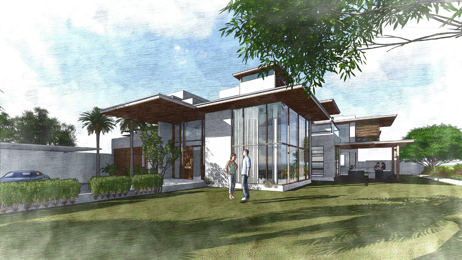
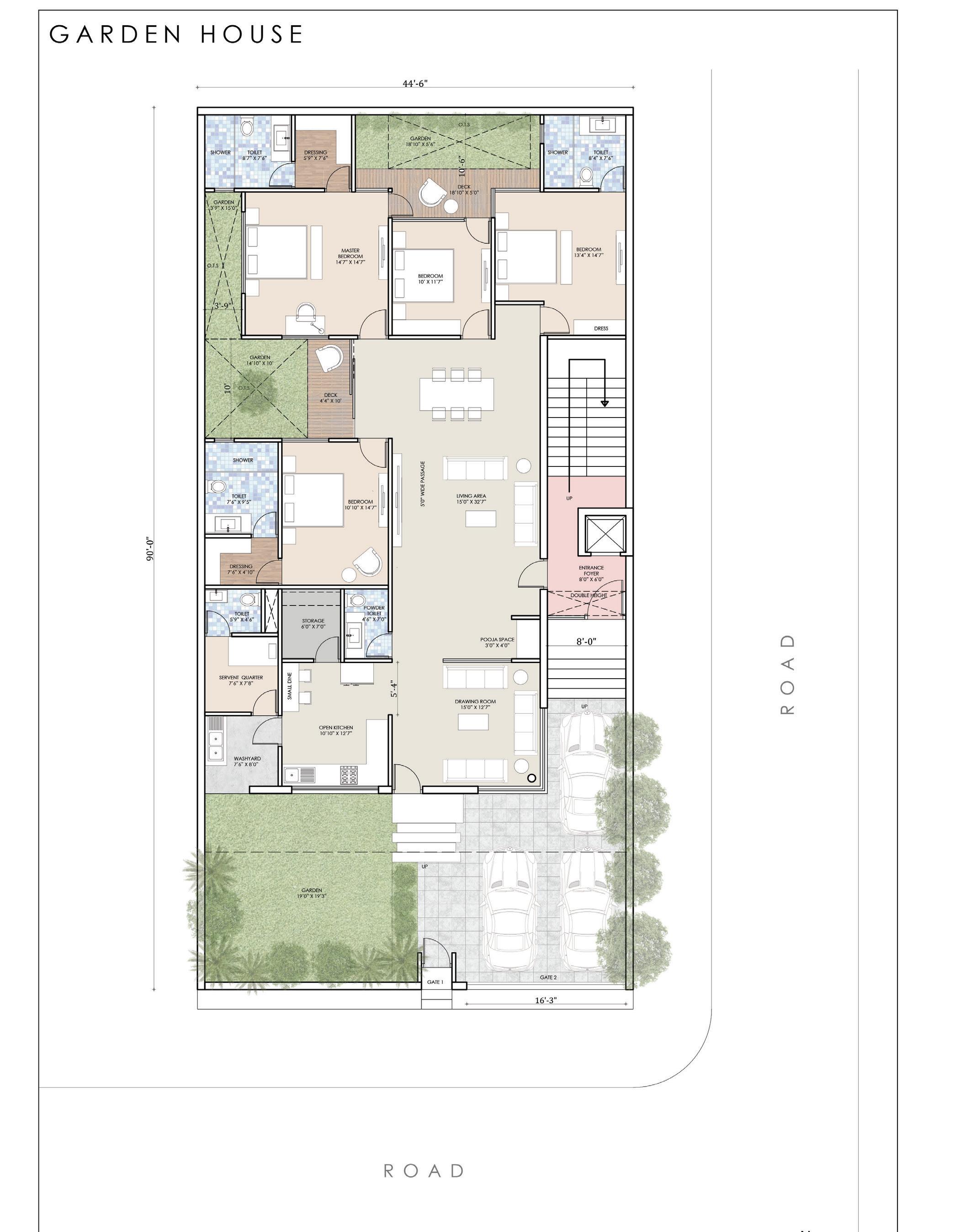
KEDAR FARM HOUSE
has been done in a way that the rooms are overlooking into the central court which becomes a secure space for kids to play since the the size of the land is big at the same time living room, kitchen and swiiming pool areas are overlooking into the vast horizon of the farm land. The project has been designed keeping in mind the vastu constrains at an extend.
The Client lives in a joint family comprising of five families along with the Grandparents and wanted a getaway farm house place in the outskirts of the city. Since the client has a joint family initial brief suggested a seperate room for each family along with some extra guest rooms all with the attached restrooms, Kitchen space, Living area and a Swimming Thepool.planning

Area: Project52,800sqft.Area:14,400sqft.
72
Location: Rajawas, Jaipur, Rajasthan
73 Plan


74 Swimming Area Dining ParkingAreaArea Farm 3D Visualisation


Dining Area

Swimming pool adjacent to Living Area

75 Sitout Area

TriundJaisalmerPradeshtrek

Himachal

76 Photography

TriundJaisalmertrektrek

77
Triund


Vinay Agarwal
Thank You
Contact: 7976742437
Email: vinayagarwalforwork@gmail.com